Embed Size (px)
Citation preview

UWE Estates and Facilities Design Guide
Chapter 8: IT Infrastructure

Chapter 8 | IT Infrastructure 2022 Page | 1
UWE Design Guide for Buildings
Table of Contents 8.1 Change Control ................................................................................................ 2 8.2 Introduction .................................................................................................... 2 8.3 Architectural Design ......................................................................................... 3 8.4 Design co-ordination & sequencing .................................................................... 4 8.5 Sequence ........................................................................................................ 5
8.5.1 Architectural Design ................................................................................... 5
8.5.2 Build ........................................................................................................ 5 8.6 UWE Comms Room Specification ....................................................................... 6
8.6.1 UWE Comms Room Specification ................................................................ 7
8.6.2 Comms Rooms Ready Condition ................................................................. 9 8.7 IT Cabling Infrastructure ................................................................................ 10
8.7.1 Standards ............................................................................................... 10
8.7.2 UTP Termination and Containment ............................................................ 10
8.7.3 Short Patching ........................................................................................ 10
8.7.4 Fibre Termination and Containment .......................................................... 11
8.7.5 UTP Outlet Labelling Convention ............................................................... 12
8.7.6 Trace and Test ........................................................................................ 13
8.7.7 Fixed IP Addresses .................................................................................. 14 8.8 Wi-Fi Infrastructure ........................................................................................ 16
8.8.1 Overview ................................................................................................ 16
8.8.2 Wi-Fi Design and Installation .................................................................... 16
8.8.3 Steps to plan, deploy & verify a Wi-Fi installation ....................................... 16
8.8.4 Refurbishment Works .............................................................................. 18
8.8.5 Wi-Fi Access Point Placement (in order of preference) ................................ 18
8.8.6 Building Fabric ......................................................................................... 22 8.9 Construction Sites ........................................................................................... 23
8.9.1 Training and Certification ..........................................................................23
8.9.2 Personal Protection Equipment ..................................................................23 8.10 Security Infrastructure .....................................................................................24
8.10.1 Access Control and Door Monitoring ...........................................................24
8.10.2 CCTV .......................................................................................................25
8.10.3 ANPR (Automatic Number Plate Recognition) ..............................................26
8.10.4 Intruder Detection Systems (IDS) ..............................................................26
8.10.5 Panic Alarms ............................................................................................ 26

Chapter 8 | IT Infrastructure 2022
Page | 2
8.1 Change Control
Version Number
Date of Issue
Chapter Ref
Brief Description of Change(s)
1.3 01/05/19 Updates to 8.2 to 8.5
2021 JAN2021 Various Amendments throughout, detailed in 2021 Version.
2022 JAN2022 Minor Amendments throughout
8.2 Introduction The purpose of this document is to specify the requirements for IT Infrastructure to be included in the design of new buildings or refurbishment works done to existing buildings within the University of the West of England.
IT infrastructure should be considered at the same time as other services (M&E, water, etc) to avoid considerable delays and added cost due to the rework required.
IT requirements should start to be established as early as RIBA stage 1 (i.e. when developing the client’s brief) and requirements discussed with UWE’s IT Services from RIBA stage 2 (when UWE stakeholders should be consulted).
UWE has a large IT estate and a wide area network consisting of both fibre and copper (Cat5e, Cat6 and Cat 6a) cabling. The infrastructure is routed through a series of ducts and in-building containment. Consideration needs to be given to breaking out of new buildings and into existing ducts in order to run fibre back to the Core network switches. Consideration must also be given to the positioning of Comms Rooms and containment

Chapter 8 | IT Infrastructure 2022
Page | 3
routes so as not to exceed the maximum cable lengths. UWE’s incumbent data cabling contractor should be involved during the development of detailed design.
IT Infrastructure is as important as power, lighting and water, and needs to come online early in the build cycle in order to commission BMS services, door access controls and other building related systems. Installing building services relies on Comms Rooms being in a ready condition, dust free, with power, lighting, ventilation, fibre connections and if required provision for cooling. The details of what constitute a ready condition, the design of comms room, and other requirements are outlined in the following sections.
8.3 Architectural Design Design is key to the successful implementation of IT Services and to the smooth running of the project. The University has an extensive duct network carrying fibres to network switches in over 150 comms rooms. Routes in and out of a new building need to be considered at the design phase, as does connecting new ducts to existing ducts. Most buildings require two sets of ducts breaking into the building at different points and running in different directions to provide resilient routes.
The Architects for a new build or UWE Surveyor involved in refurbishments should consider the following:
How will Fibre Optic cables come into the building? Most buildings will require two cables to enter the building from diverse routes. Fibre cables from the network switches located in the building’s comms rooms will need to run through diverse duct routes to the core network nodes, which are 2B11 and 2D86 at Frenchay Campus, 0F5 and 0B4 at Bower Ashton and 1B31 and BH047 at Glenside.
What duct routes are required and how will these connect to existing UWE duct routes? Diverse duct routes will usually be required to provide resilience. A member of the ITS infrastructure team should be involved in pre-construction meetings with the Project Team. Involvement at this stage will highlight risks associated with existing fibre cable routes, or other existing ITS facilities.
Where will the Comms Rooms be positioned? Comms Rooms need to comply with the minimum specification outlined later in this document. Cable lengths need to comply with the industry standards, meaning there may be a requirement for multiple Comms Rooms. Fibre cables connect the comms rooms within the building to the core network nodes. Copper Ethernet cable connect the network switch to the network outlet. The cable running from the switch to the outlet must not exceed 90m. This means the number of comms rooms and where they are placed in the

Chapter 8 | IT Infrastructure 2022
Page | 4
building is determined by where network outlets are required. It is worth remembering that cable routes through containment might be longer. Comms rooms should also be accessible from an open access area i.e. without the need to walk through a classroom or office. Nor should a comms room be an access route to another room or riser. Ideally at least one wall of the comms room should be external facing so that heat may be extracted from the room more easily, especially where air conditioning is not suitable.
Copper Ethernet Cable Routes through the Building and to Network Outlets: The number of network outlets and where they need to be is a fundamental requirement that will determine the design of the building. The client needs to provide this information at the design phase. It determines how many comms room are needed and where they need to be located. It also determines the best containment routes through the building. The containment route can impact the length of a cable. Do not exceed the 90m cable length limit.
Where will the network outlets go and what are the cable containment routes required to get to them? The containment routes from Comms Room to network outlets can be considerably longer than a straight line from comms room to outlet. Containment routes and the layout of comms rooms, network outlets in rooms and their intended use should all be included in the BIM models.
What will the network outlets be used for? What an outlet is used for will determine how the network switch port is configured.
8.4 Design co-ordination & sequencing The sequence of the build or refurbishment works is agreed between the Principal Contractor and UWE, beginning in the pre-construction phase while the programme and construction phase plan are prepared. UWE IT Services must be engaged as early as possible.
Before foundations are laid, the duct routes should be known and accessible. Past experience has shown that the location of the contractor compounds and placement of plant equipment sometimes fails to take into account access to the building and access to duct routes (e.g. positioning site cabins on top of manhole covers). This can introduce delays and additional costs when fibres need to be run into the building or any other buildings on campus. Agreement should be made prior to any work starting between UWE (Estates) and building contractor for access to any existing ducts within the compound so that any repairs and installations can be carried out without excessive delay.
Chapter 8 | IT Infrastructure 2022
Page | 5
UWE IT Engineers are the only personnel permitted to install network switches and only once fibre cables have been installed and connected back to appropriate Core Network switches. Comms Rooms must meet the minimum specification required before equipment is installed.
The commissioning of BMS devices, sensors, cameras, access control, etc. can only be completed once the network switches have been installed and when any fixed IP addresses required have been allocated.
UWE IT Services will install Wi-Fi and Audio Visual equipment following the installation of the network switches. The installation of further equipment, PCs, Printers, etc. is usually done following handover of the building from the principal contractor to the University.
8.5 Sequence 8.5.1 Architectural Design
1. Building duct routes specified, including break out of building and break into existing
ducts. 2. Comms Room placement agreed, taking account of cable lengths and containment
routes. 3. Comms Rooms specified, taking account of UWE requirements, see Section 4.
8.5.2 Build
4. Contractor compound and plant equipment placements not restricting access to
existing cable and other service ducts. 5. Live data cables that are routed through an area that is being refurbished must be
clearly marked or moved out of the way of any potential damage. UWE’s incumbent cabling contractor must be used to do this work.
6. Any Wi-Fi access points that are located in an area that is being refurbished must be removed and stored for safe keeping, again by UWE’s incumbent cabling contractor. Once building work is complete, the APs will be reinstalled in designated locations, agreed during the design phase.
7. Any comms cabinet in an area being refurbished must be protected from dust or other contaminants without hindering the cooling of network equipment located in the cabinet. ITS and the incumbent cabling contractor can advise.
8. Comms Rooms in ready state (with power, lighting, secure door, ventilation or cooling as required) to enable commissioning of building management systems, etc.
9. Fibre Optic cables installed and connected to the UWE core network switches. 10. Structured Copper Ethernet cables installed, terminated and labelled at the patch
panel and outlet (see note below). All data cabling work must be done by UWE’s incumbent cabling contractor, although they can be engaged as a sub-contractor of the M&E contractor on the build project
Chapter 8 | IT Infrastructure 2022
Page | 6
11. Network switches configured and installed. 12. BMS, Access Control, CCTV, etc. devices installed and commissioned. 13. FIRE STOPPING all wall, floor and ceiling penetrations. 14. ITS infrastructure are required to install the network switches prior to the
commissioning of building systems, access control, CCTV, etc. The commissioning schedule should be discussed with ITS infrastructure to ensure the building is delivered on time. Installation and commissioning of the network switches must take place 6 weeks prior to handover to allow for time to commission the building systems and configure network outlets.
15. Wi-Fi and AV equipment installed
For new remote sites, the Project must request ITS to engage with a service provider such as BT OpenReach to provide a leased fibre link to the boundary of the remote site from UWE main server room in Frenchay 2B11. ITS will then instruct the incumbent cabling contractor to install fibre within the boundary of the remote site to the designated server room.
Note: The configuration of end user network outlets must be done at least one week (5 working days) prior to use by end users. The cabling contractor should therefore be working to a completion date at least two weeks prior to the end date. Failure to allow enough time for the installation, configuration and testing of the network may result in delays to the project.
8.6 UWE Comms Room Specification
Room Configuration
Specific element
Implementation to be defined by the project, but must meet the minimum requirements as per diagram below
Electrical Distribution Boards
New Comms Rooms must have dedicated electrical circuits for • Racks • Lighting • Cooling Each circuit should be individually protected to avoid problems affecting other circuits.
Small Power • 2x 32amp Commando Sockets located as per diagram below • Rack mounted sequencing PDU strips with the network
connection patched into the patch panel. Lighting Lighting must ensure illumination of both the front and the rear
of the cabinets. It may be necessary to place lighting off centre. Containment Determined on a project by project basis. Cable entry from
above the cabinet is preferable. . See details regarding ceilings below.
Fire Detection As specified by UWE building specifications Environment Temperatures in the Comms Rooms must never exceed 26°C.
Mechanical Cooling Free cooling / air conditioning systems should be used. Free- cooling should take preference. Type of free-cooling should be dependent upon number of switches. Mechanical cooling if required must be N+1 if there are more than 2 cabs of switches;
Where AC is required, wall mounted split units should be
Chapter 8 | IT Infrastructure 2022
Page | 7
installed on the wall facing the front of the cabinet. UWE is
investigating the possibility/ technical solutions for reducing the temperature to 22°C if an operative is working in the room. Monitoring of the AC, room temperatures and the ability to control the units remotely by the UWE Facilities Department and IT Services should be incorporated into the design.
Pipework Pipework containing liquid of any kind or drains should not be above or below Comms Rooms.
Fabric Room Placement
Direct access to the Comms Rooms is a basic requirement. It must be possible to access the Comms Room without going through or via another room.
The comms room should not be an access route to any other room or space, including riser cupboards, since any doors other than the entrance would restrict usable space and cabinet positioning.
Security Comms Rooms should be fitted with the UWE standard door access control, but also have a bypass key override facility in the event of power failure.
Ceiling False Ceilings should not be fitted to Comms rooms. The fitting of a ceiling impedes the installation of network cables, and the use of cable trays and other containment.
Cabinet Sizes Standard 42U full size cabinets 800x1000mm should be used Switches Access layer switches to be specified, sourced and installed by
UWE IT Services. Cabinet Placement
First cabinet must be placed against the wall as per diagram (Figure 1.)
Technical Information
Cabling Comms Rooms should be positioned so that cables between the Comms Room and data outlets do not exceed 90m.
Cabling must comply with Copper Ethernet standards and Building Regulations.
Single Mode Fibre to cabinets must originate from two of the core network nodes. The rooms which contain core network nodes must be confirmed by UWE IT Services.
The two fibre cables must travel along diverse routes and enter the building at different locations. This reduces the risk of a single cut impacting services.
UPS Requirements
Where UPS is required for Business continuity, the UPS should be specified by IT Services. Where UPS is required the need to keep the batteries cool is very important, this ensures their longevity. In this case the room temperature should be kept below and not exceed 25 degrees C.
Patching All outlets must be patched into network switches using 20cm patch leads.

Chapter 8 | IT Infrastructure 2022
Page | 8
Good Practice E22 IT and Comms Room Energy Consumption - Dedicated IT and communication rooms have a calculated DCIE (data centre infrastructure efficiency) of 70% or greater.
8.6.1 UWE Comms Room Specification
Chapter 8 | IT Infrastructure 2022
Page | 9
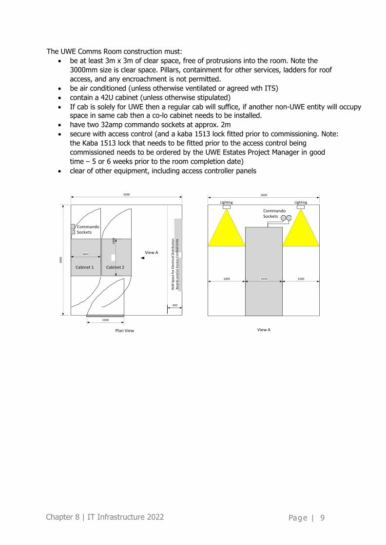
The UWE Comms Room construction must: • be at least 3m x 3m of clear space, free of protrusions into the room. Note the
3000mm size is clear space. Pillars, containment for other services, ladders for roof access, and any encroachment is not permitted.
• be air conditioned (unless otherwise ventilated or agreed wth ITS) • contain a 42U cabinet (unless otherwise stipulated) • If cab is solely for UWE then a regular cab will suffice, if another non-UWE entity will occupy
space in same cab then a co-lo cabinet needs to be installed. • have two 32amp commando sockets at approx. 2m • secure with access control (and a kaba 1513 lock fitted prior to commissioning. Note:
the Kaba 1513 lock that needs to be fitted prior to the access control being commissioned needs to be ordered by the UWE Estates Project Manager in good time – 5 or 6 weeks prior to the room completion date)
• clear of other equipment, including access controller panels
Plan View View A
3000
1000
Wal
l Spa
ce fo
r Ele
ctric
al D
istrib
utio
n Bo
ards
and/
or A
cces
s Con
trol
Uni
ts
Lighting Lighting

Chapter 8 | IT Infrastructure 2022
Page | 10
Figure 1.
8.6.2 Comms Rooms Ready Condition
Network equipment will only be installed once the Comms Room is in a ready condition. Due to the security risks associated with IT networks, only authorized UWE IT staff can install network equipment, and only when the following conditions are met:
• The comms room door must be secure using a UWE standard plant room Kaba lock.
(Please note that use of a Kaba lock is as an interim before the access control system is commissioned)
• Power to the comms room is constant, there are no fluctuations or outages beyond what constitutes everyday tolerances. If contractors are aware that further planned power outages will be necessary in a given Comms Room after switch installation, this must be declared in advance to UWE IT Services.
• The specified comms cabinet/s are installed and fibres are terminated and labelled at both the cabinet end and the Core network ends.
• Lighting is installed and provides illumination of both the front and back of the cabinet.
• Cooling, if required, is installed, tested and shown to provide the specified temperatures.
• The level of dust from building works in the room is minimal, a damp wipe should of cabinets and floors have taken place if required, all debris and rubbish removed and there are no further works that will generate significant levels of dust.

Chapter 8 | IT Infrastructure 2022
Page | 11
• UWE’s incumbent cabling contractor will connect the cabinet located in the comms room to the core network nodes in Frenchay 2B11 and 2D86 via fibre cables. They will also terminate the copper Ethernet cables to patch panels in the comms cabinet, ensure that comms cabinet rails have been located to accommodate the network switches and install the required power distribution units.
8.7 IT Cabling Infrastructure 8.7.1 Standards
The three standards are formally titled ANSI/TIA/EIA-568-B.1-2001, -B.2-2001, and -B.3- 2001.
Copper cabling in new buildings to be CAT 6a and cabling installation will be provided with a manufacturer warranty for 25 years. New buildings shall be provided with blanket Wi-Fi coverage. Responsibility for the Wi-Fi design and specification is with UWE IT Services.
UWE Facilities must make contractors aware of fibre duct routes and access panels across the UWE campuses, where the contractor work may interfere with these services. Where the contractor is not aware, they must seek instruction from UWE Facilities.
8.7.2 UTP Termination and Containment
Requirements for any UTP cabling are as follows:
• Cables to be terminated in the communications room on 24 port RJ-45 patch panels. • Cables to be terminated at the outlet on an RJ-45 outlet with spring loaded shutters. • Outlets to be white plastic, installed in either flush mounted wall outlets or within
dado trunking. • The containment to be pervasive, continuous and allow for 50% more cables than
originally installed. • The containment paths must follow routes in accessible areas, such as corridors. All
containment and cabling restraining should be in line with current UK Building Regulations.
• Where there is a requirement to install cabling through existing containment and there is not sufficient capacity new containment should be installed, this would need relevant approval / planning and updates to architectural plans and BIM.
• During a refurbishment, all redundant cabling should be removed from containment.
• A blue 3m patch cord is to be provided for each outlet.
8.7.3 Short Patching
A Short Patching policy has been adopted for access layer network switches in all UWE ITS comms rooms. Short patching is a one patch panel port to one switch port arrangement that enables quick identification of port numbers and reduces the time to configure and make ports available for users. A one to one arrangement means for the number of outlets installed, there needs to be a corresponding number of network switch ports available. The installation of fifty network outlets into a building will necessitate the installation of two 48

Chapter 8 | IT Infrastructure 2022
Page | 12
port switches.
Chapter 8 | IT Infrastructure 2022
Page | 13
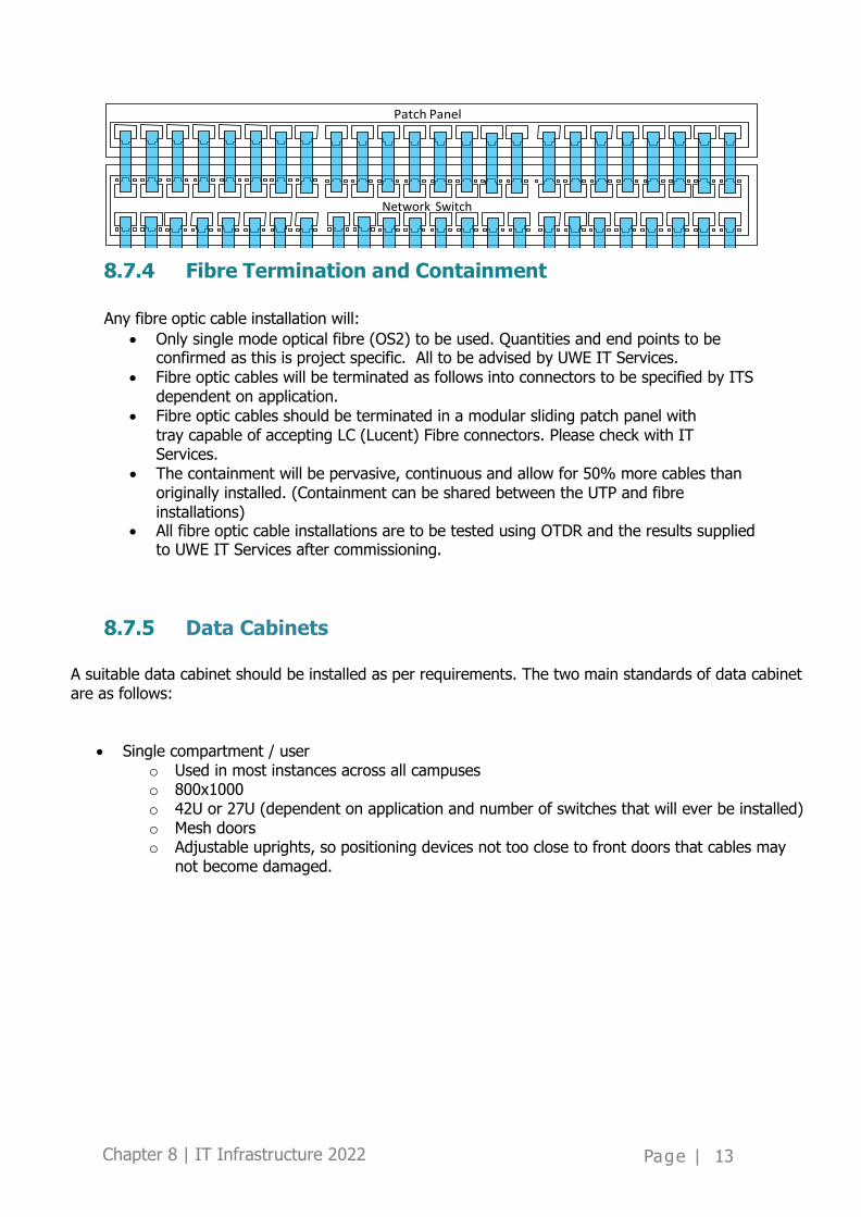
8.7.4 Fibre Termination and Containment
Any fibre optic cable installation will:
• Only single mode optical fibre (OS2) to be used. Quantities and end points to be confirmed as this is project specific. All to be advised by UWE IT Services.
• Fibre optic cables will be terminated as follows into connectors to be specified by ITS dependent on application.
• Fibre optic cables should be terminated in a modular sliding patch panel with tray capable of accepting LC (Lucent) Fibre connectors. Please check with IT Services.
• The containment will be pervasive, continuous and allow for 50% more cables than originally installed. (Containment can be shared between the UTP and fibre installations)
• All fibre optic cable installations are to be tested using OTDR and the results supplied to UWE IT Services after commissioning.
8.7.5 Data Cabinets
A suitable data cabinet should be installed as per requirements. The two main standards of data cabinet are as follows:
• Single compartment / user o Used in most instances across all campuses o 800x1000 o 42U or 27U (dependent on application and number of switches that will ever be installed) o Mesh doors o Adjustable uprights, so positioning devices not too close to front doors that cables may
not become damaged.
Network Switch

Chapter 8 | IT Infrastructure 2022
Page | 14
Figure 1 – Single Compartment / User Cabinet
• Co-Location / multiple users
o To be used where multiple users exist, such as UWE and the Accommodation Network provider.
o 800x1000 o 42U, number of compartments up to 4 dependent on application. o Mesh doors o Patch Panels delivered to relevant compartment
Figure 2 – Co-location / Multiple Users cabinet
8.7.6 Frenchay Fibre Ring Ducts and Pillars

Chapter 8 | IT Infrastructure 2022
Page | 15
The university is deploying a Fibre ring around the Frenchay campus with access via the use of feeder pillars. This will allow any new builds / refurbishments to break into ducts that feed into the Fibre ring. It is expected that
• Connections to new builds / refurbishments to break out of buildings into ducts connected to the Fibre ring
• Connections to new builds / refurbishments to use 4 conduit Fibre tube with 12 Fibres occupying one of the tubes, unless variation required due to requirements. Check with IT Services.
• Each of the two new connections from the comms room using diverse routes will terminate in two different feeder pillars which form the Fibre ring. Here they can be patched back to the main core routers in 2B011 and 2D086. Please check with IT Services with regards to which feeder pillars to use.

Chapter 8 | IT Infrastructure 2022
Page | 16
8.7.7 UTP Outlet Labelling Convention
Each network outlet must be labelled (black text on yellow label) with a unique reference, as illustrated in Figure 3.
• At the Comms Room end, the unique reference should be the name of the room containing the outlet, and the increment number. The increment number is a three- digit number with leading zeroes, assigned by the cable installer and identifying the actual outlet within the room.
• At the outlet end, the unique reference should be the name of the Comms Room where the cable to the outlet is patched, and the same increment.
Comms Room Ref. Increment
Comms Room Ref.
Increment
Room (e.g. 2D053) Outlet Room (e.g. 2D054) Outlet
Room Ref. Increment Room Ref. Increment
Comms Room (e.g. 2B060)
Thus for the 6th network connection in Comms Room 2B060, where the outlet is positioned in room 2D054, at the outlet end the label will read 2B060/006 and at the Comms Room end the label will read 2D054/006.
Note: there is no difference between the labelling of data outlets and telephone outlets. Data and telephone cables are patched to different locations within the Comms Room, but labels should still fit in with, and remain unique to, the data outlet labelling. For example, if an outlet in room 2D054 designated for telephone use is the 71st outlet in comms room

Chapter 8 | IT Infrastructure 2022
Page | 17
2D060 it will still be labelled 2D060/071 at the outlet end and 2D054/071 at the comms room end.
It should also be noted that, for each comms room within a building, the labelling can start with other end/001 since the uniqueness comes at the outlet end where the comms room is specified as part of the label.
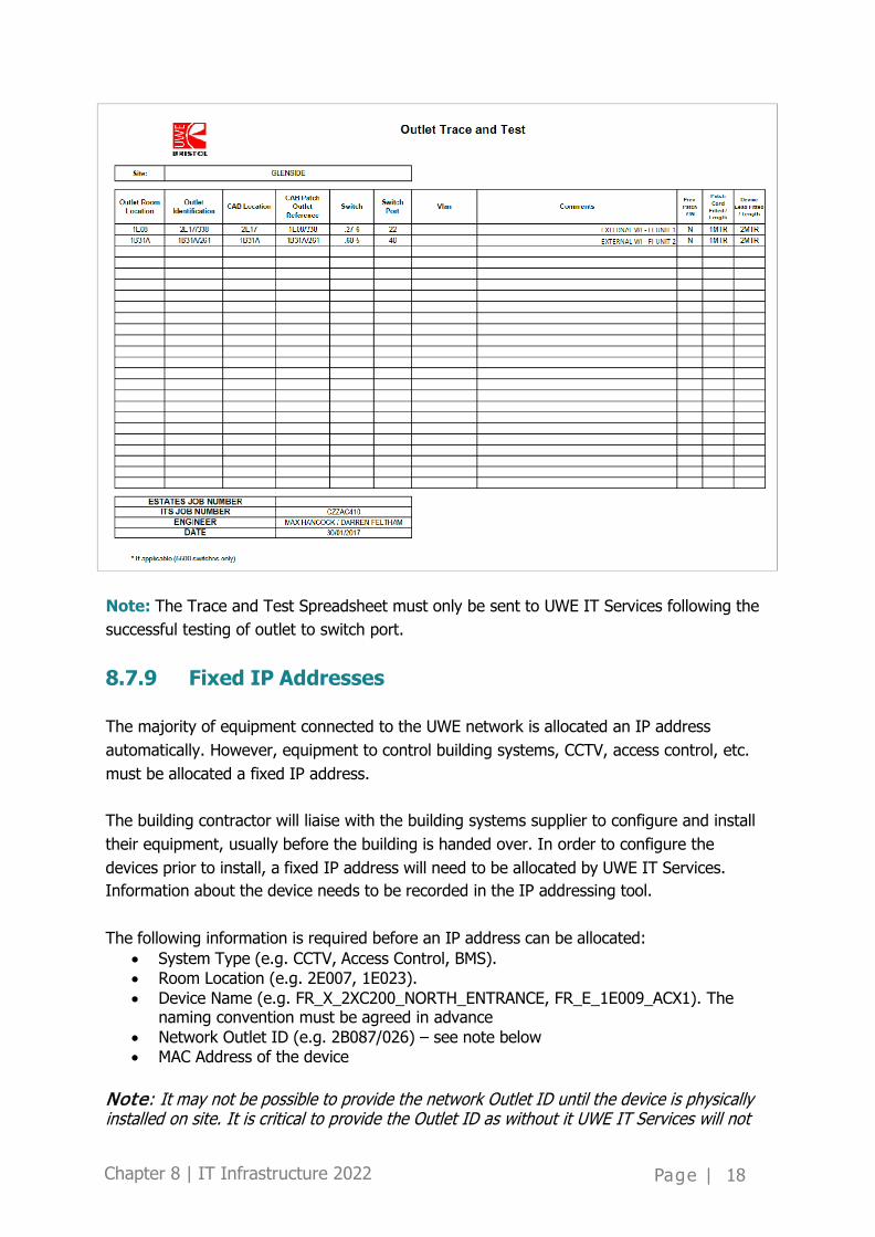
8.7.8 Trace and Test
Once the network switches have been installed, the cabling contractor is required to carry out a trace and test of each copper ethernet cable. The trace and test information critically provides information to ITS which network to configure an outlet for; staff network, student network, printer network, building management system network, etc. With this is mind, the client must have specified what each and every outlet will be used for and communicated that to the cabling contractor via the UWE Estates PM.
All switch ports must be configured with description information and the VLAN appropriate for the equipment being connected to that port, i.e. a BMS device is connected to the BMS VLAN, a Staff PC is connected to the staff VLAN and a student PC is connected to the student VLAN.
In order to configure the switch port, it is necessary to know which network outlet is connected to which switch port, and in turn what will be plugged into the network outlet. The standard Trace and Test should contain the information in the following format.
Chapter 8 | IT Infrastructure 2022
Page | 18
Note: The Trace and Test Spreadsheet must only be sent to UWE IT Services following the successful testing of outlet to switch port.
8.7.9 Fixed IP Addresses
The majority of equipment connected to the UWE network is allocated an IP address automatically. However, equipment to control building systems, CCTV, access control, etc. must be allocated a fixed IP address.
The building contractor will liaise with the building systems supplier to configure and install their equipment, usually before the building is handed over. In order to configure the devices prior to install, a fixed IP address will need to be allocated by UWE IT Services. Information about the device needs to be recorded in the IP addressing tool.
The following information is required before an IP address can be allocated:
• System Type (e.g. CCTV, Access Control, BMS). • Room Location (e.g. 2E007, 1E023). • Device Name (e.g. FR_X_2XC200_NORTH_ENTRANCE, FR_E_1E009_ACX1). The
naming convention must be agreed in advance • Network Outlet ID (e.g. 2B087/026) – see note below • MAC Address of the device
Note: It may not be possible to provide the network Outlet ID until the device is physically installed on site. It is critical to provide the Outlet ID as without it UWE IT Services will not
Chapter 8 | IT Infrastructure 2022
Page | 19
be able to configure the outlet for the VLAN appropriate for the device, i.e. the outlet for a CCTV needs to be configured to connect to the CCTV network.
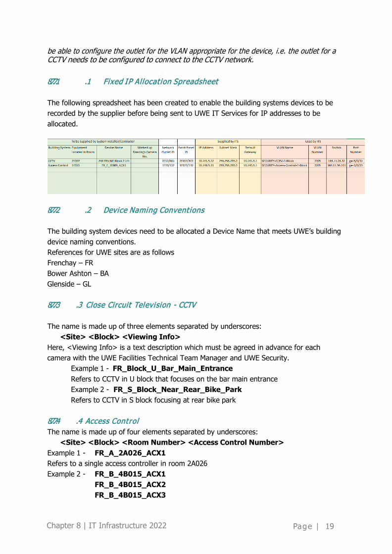
8.7.7.1 .1 Fixed IP Al locat ion Spreadsheet
The following spreadsheet has been created to enable the building systems devices to be recorded by the supplier before being sent to UWE IT Services for IP addresses to be allocated.
8.7.7.2 .2 Device Naming Conventions
The building system devices need to be allocated a Device Name that meets UWE’s building device naming conventions. References for UWE sites are as follows Frenchay – FR Bower Ashton – BA Glenside – GL
8.7.7.3 .3 Close Circuit Television - CCTV
The name is made up of three elements separated by underscores:
<Site> <Block> <Viewing Info> Here, <Viewing Info> is a text description which must be agreed in advance for each camera with the UWE Facilities Technical Team Manager and UWE Security.
Example 1 - FR_Block_U_Bar_Main_Entrance Refers to CCTV in U block that focuses on the bar main entrance Example 2 - FR_S_Block_Near_Rear_Bike_Park Refers to CCTV in S block focusing at rear bike park
8.7.7.4 .4 Access Control The name is made up of four elements separated by underscores:
<Site> <Block> <Room Number> <Access Control Number> Example 1 - FR_A_2A026_ACX1 Refers to a single access controller in room 2A026 Example 2 - FR_B_4B015_ACX1
FR_B_4B015_ACX2 FR_B_4B015_ACX3

Chapter 8 | IT Infrastructure 2022
Page | 20
Refers to three access controllers in 4B015
8.7.7.5 .5 Bui lding Management System – BMS
The contractor must confirm with the UWE Facilities BMS Manager
8.7.7.6 .6 Monitoring & Targeting (M& T)
The contractor must confirm with the UWE Facilities Technical Team Manager
8.7.7.7 .7 Intruder Alarm System
The contractor must confirm with the UWE Facilities Technical Team Manager
8.8 Wi-Fi Infrastructure 8.8.1 Overview
UWE provides ubiquitous Wi-Fi across the campuses. This service is expected to be fast, reliable and provide seamless access to teaching and learning resources regardless of the devices in use.
Wi-Fi Access Points (APs) are strategically placed in buildings to maximise coverage and minimise interference caused by other APs and building materials. Correct placement of these APs within a building fabric is key to providing a high quality and reliable service. This section outlines best practice for the location of Wi-Fi APs. These requirements must be fed into the design for both new buildings as well as refurbishment projects.
8.8.2 Wi-Fi Design and Installation
To provide the quality of Wi-Fi coverage demanded by students and staff at the University, UWE IT Services will complete a detailed Wi-Fi design. It is important that UWE ITS are involved at the initial building design stage to ensure that Wi-Fi design is an integral element of new buildings and refurbishments. Wi-Fi designs that occur after the building works are complete increase cost and time and often compromise on coverage and aesthetics.
It is important the note that any changes to the building design must be communicated to UWE IT Services.
8.8.3 Steps to plan, deploy & verify a Wi-Fi installation:
1. The UWE Estates Surveyor / Project Manager should provide UWE IT Services with each iteration of building drawings in .dwg format as soon as they are available. The .dwg

Chapter 8 | IT Infrastructure 2022
Page | 21
drawings should include occupancy numbers for each room and the room number designations (if known).
2. UWE IT Services staff need to meet with the UWE Estates Surveyor, Architect and UWE’s
incumbent cabling contractor to further understand the design. In particular… • Planned usage of each room – Social, GPT (General Purpose Teaching), etc. • Footfall figures in each area • Materials used in building fabric – walls, floors, windows • Type of ceiling – suspended, raft, open/industrial • Any other potential interference sources, i.e. microwave ovens, PIR Sensors • Any design anomalies or aspirations
3. UWE IT Services will create a predictive Wi-Fi coverage survey (see figure below) using
Ekahau modelling software, based on the building drawings and requirements. The predictive survey determines the type of Wi-Fi access points required and their optimum location. UWE IT Services will always install Wi-Fi Access point that meet the latest IEEE ratified standard.
Figure 4.
4. UWE IT Services will provide a building drawing marked with the Wi-Fi access point locations to the UWE Estates Surveyor. It is then the responsibility of the building project team to determine the most appropriate containment routes, cable runs, etc. to the Access Point locations, ensuring that cable lengths are within specifications. In order to support the use of BIM modelling, desired WiFi locations may also be marked in the BIM model of the building. Ultimately the final locations should be marked in the model.
5. The number of locations to provide coverage will in turn determine the number of Wi-Fi
Access Points units required. Building projects fund the purchase of Wi-Fi APs, therefore UWE ITS will require a project cost code before the APs can be procured.
6. Following a successful trace and test by the cabling contractor of the network outlets
designated for the Access Points, UWE IT Services will configure the outlets, and prepare

Chapter 8 | IT Infrastructure 2022
Page | 22
the Access Points. Each Access Point is labelled with a location and outlet identifier. It is imperative that the correct Access Point is installed in its associated location.
7. The cabling contractor will install the Access Points once the building is dust free and
network outlets / Access Points are configured and labelled. Following successful installation, the cabling contractor must inform UWE IT Services, who will bring the units into service.
8. UWE IT Services will then carry out a post installation survey using Ekahau modelling
software. This survey verifies that the Wi-Fi installation delivers the required service and coverage detailed in the predictive survey. To perform the survey UWE IT Services will require access to all rooms within the new building/refurbishment project. Therefore the post installation survey should take place after building handover from the principal contractor but before occupation.
9. If all Wi-Fi coverage is as required, the coverage maps are published internally. If there
are areas of limited or no coverage, UWE IT Services will work with the Estate Surveyor to retro fit additional Access Points.
8.8.4 Refurbishment Works
Where refurbishment works are planned in an area that already contains Wi-Fi Access Points, the units must be removed by UWE’s incumbent cabling contractor and given to UWE ITS for safe keeping before any building works start. Following completion of works, the process steps 6 and onwards apply.
For more extensive refurbishment works, removals of walls, changes to materials (glass partitions) it may be necessary to carry out all the steps above.
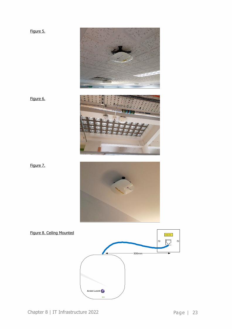
8.8.5 Wi-Fi Access Point Placement (in order of preference)
Access Points require a single network outlet. For ceiling mounted units, the outlet should be within 300mm of Access Point to negate the use of surface mounted containment (Figure 8). For wall mounted units, the outlet should be within 200mm of the Access Point.
8.8.5.1 .1 Option 1 – Ceil ing Mount
Access Points should be placed beneath suspended ceiling tiles (Figure 5) on the structural beams of a building (Figure 6) or directly to the ceiling fabric (Figure 7). They must be mounted using manufacturer designed brackets. These are the most preferred options and should be encouraged in all design specifications as they provide opportunity for the best Wi-Fi coverage.
Chapter 8 | IT Infrastructure 2022
Page | 23
Figure 5.
Figure 6.
Figure 7.
Figure 8. Ceiling Mounted
Chapter 8 | IT Infrastructure 2022
Page | 24
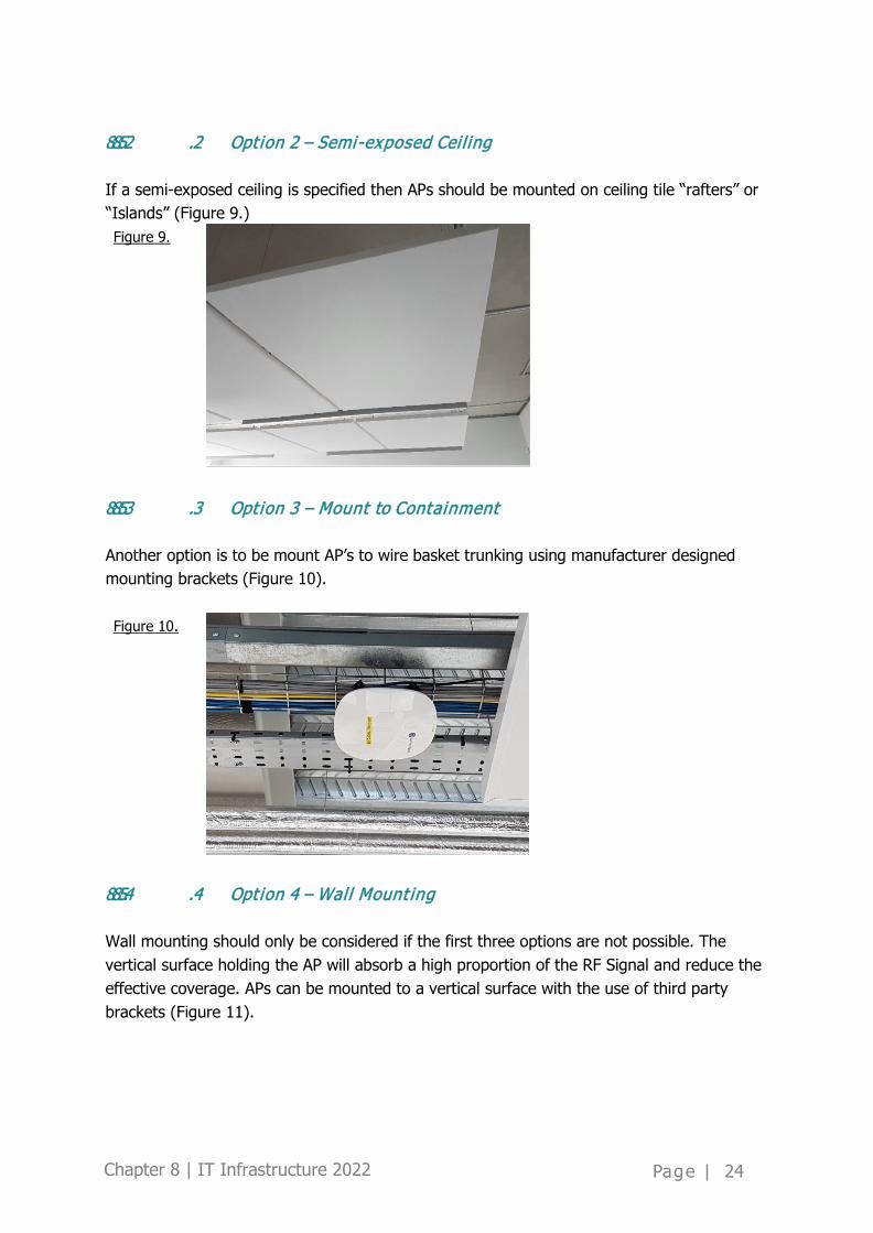
8.8.5.2 .2 Option 2 – Semi-exposed Cei l ing
If a semi-exposed ceiling is specified then APs should be mounted on ceiling tile “rafters” or “Islands” (Figure 9.) Figure 9.
8.8.5.3 .3 Option 3 – Mount to Containment
Another option is to be mount AP’s to wire basket trunking using manufacturer designed mounting brackets (Figure 10).
Figure 10.
8.8.5.4 .4 Option 4 – Wall Mount ing
Wall mounting should only be considered if the first three options are not possible. The vertical surface holding the AP will absorb a high proportion of the RF Signal and reduce the effective coverage. APs can be mounted to a vertical surface with the use of third party brackets (Figure 11).

Chapter 8 | IT Infrastructure 2022
Page | 25
Figure 11.
The network outlet for wall mounted Access Points should be within 200mm, where the outlet is also being mounted to the wall. Access Points and network outlets should be at a miniumum height of 2.4m (2400mm) (Figure 12).
Figure 12. Wall Mounted
200mm
2400mm

Chapter 8 | IT Infrastructure 2022
Page | 26
8.8.6 Building Fabric
The building fabric and materials used can severely hamper the effectiveness of Wi-Fi Access Points.
Large internal features made of metal or glass should be avoided, as they cause major RF reflections which degrade Wi-Fi performance significantly. Suspended ceilings provide the best options for mounting Wi-Fi Access Points, but consideration must be given to servicing and replacing the units. Placement on very high ceilings and atriums requiring specialist height access equipment is not permissible.
Wi-Fi is most definitely a service that users expect to have available regardless of where they are on campus. APs need to be in ‘line of sight’ of the users device to maximise connectivity and reliability. With this in mind aesthetics must be considered secondary to the placement of APs in all circumstances. Access Points cannot be hidden to satisfy aesthetic aspirations.
As of September 2017, the Access Points used to provide UWE Wi-Fi are only manufactured in White.
Where possible the following should not be used or Wi-Fi Access Points should not be located within 2 metres of them.
• Metal sheeting of any kind • Chain Link fencing or wire sheeting • Glass partitions • Metal laced safety glass • Microwave Ovens • DECT phone transmitters • PIR Security Sensors • Radio Microphone Systems • Bluetooth enabled devices of any kind • Computer/Display monitors and projectors • Surfaces containing a large body of water, i.e. fountains etc • Plant (Air Conditioning, Electrical) • Other Wi-Fi Access Points not part of the same Enterprise • Concrete or Metal Pillars or structures containing rebar

Chapter 8 | IT Infrastructure 2022
Page | 27
8.9 Construction Sites The majority of buildings constructed on the UWE campuses have a requirement for building management systems, access control and CCTV requiring connections to the site network.
These systems are usually installed by the contractor prior to the building being handed over to UWE. In order to commission the systems, UWE IT Services network engineers need to install network equipment into the designated comms room whilst the site is still a construction site managed by the contractor.
8.9.1 Training and Certification
Access to construction sites is controlled by the Principal Contractor and therefore UWE IT engineers must adhere to the Health and Safety requirements specified by the Principal Contractor.
If for any reason further conditions are required in order to allow access, the Contractor must make these known to UWE IT Services at the beginning of the build. Failure to do this may result in delays to the Project.
8.9.2 Personal Protection Equipment
UWE IT Services carry out installations of network equipment into designated construction sites on a regular basis. It is expected that Personal Protection Equipment (PPE) is required to be worn. In general, the following is used within UWE:
• Hi Vis vest • Safety shoes or boots with steel toe cap • Helmet • Goggles • Gloves appropriate to the task
Where the PPE requirements are above and beyond that specified above, the Contractor must make these requirements known to UWE IT Services at the beginning of the build. Failure to do this may result in delays to the Project.

Chapter 8 | IT Infrastructure 2022
Page | 28
8.10 Security Infrastructure The overarching security strategy is set out in part 3 of the design guide. This section explains specific elements of the strategy in more depth where it impacts on the IT infrastructure. The design guide chapter which deals with Electrical Engineering Design provides details about suppliers to be used and, of course, electrical system design.
8.10.1 Access Control and Door Monitoring
This system enables UWE to employ a degree of security whilst maintaining access for staff and students – 24/7 if required.
The access control system can be set-up to enable different groups access at different times - for example a certain group, say staff, can be granted access 6am to midnight whilst undergraduates given 8am to 7pm and postgraduates a different time schedule again. The occupying client is responsible for ensuring the necessary risk assessments are carried out for access outside of core UWE working hours.
Each door can be set up individually and this is carried out in agreement with the occupying client. On going amendments to this can be implemented by the Security Systems Team in liaison with the occupying client, ideally via a few key client contacts.
In addition to the access control doors the access control system can be used to monitor doors, such as fire exits, and trigger an alarm in the 24/7 control room at Frenchay if the door security is breached. The alarms will be set-up to trigger on high risk doors (e.g. Nuclear Suite) and on all perimeter doors outside of core hours.
Access control should come on-line on all perimeter doors at an agreed time and UWE Cards used by staff and students to gain access after that time. This is to maintain a suitable level of security outside of core UWE hours whilst enabling staff and students to continue to use the space. In general when a building is relatively quiet those using the building feel safer if they know the building is secure.
Access control to be installed on the following doors:
• All perimeter entrances • Where practical on all internal doors which mark the perimeter of a Faculty/Service
area, e.g. HAS internal perimeter doors • Rooms that require restricted access but to a significant number of people (where a
key lock is not suitable), e.g. BPTC, Postgraduate spaces etc. • Plant rooms • Comms rooms • Where specialist, high value or desirable equipment is installed • Central postrooms • Central stores accessed by large numbers of people, e.g. stationery stores

Chapter 8 | IT Infrastructure 2022
Page | 29
Door Monitoring to be installed on the following doors: • All external doors other than entrances to be monitored via the access control
system, e.g. all fire exits
High risk areas with access control are to be identified in liaison with the occupying client and alarms set-up in the 24/7 control room.
Access control will NOT be installed on the following as a matter of course:
• Lecture theatres • 24/7 PC labs (unless they contain specialist, high value or desirable equipment is
installed) • Teaching rooms • Meeting rooms • Offices • Cleaners’ cupboards
8.10.2 CCTV
Although CCTV acts as a good deterrent, increases the feeling of safety and security, and can on occasion be useful in providing images for identification and evidential purposes it is neither practical nor cost effective to cover all areas of a campus.
Where practically possible CCTV will be installed and deployed in the following areas:
• To meet licensing requirements • Bike parks and racks • Site perimeter vehicular access and egress • General perimeter coverage for pedestrian access to site • Main entrances to buildings • 24 hour IT labs • Areas with expensive/desirable equipment, e.g. iMacs • Bus stops • Taxi rank • Main walkways and thoroughfares e.g. from campus to Village (Frenchay), FBL new
build atrium • Key vehicle barriers • East Reception (24 hour) • Cash Office • ‘Hotspots’ based on incidents/crime/use of campus • Internal spaces as discussed and agreed with occupying clients and dependant on
site specific use .e.g. FBL Trading Room
Please note it is not the intention of the CCTV system to cover car parks across campuses. There are some existing bicycle racks which cannot be covered by CCTV as there is no data to these areas, the Travel Team have been made aware of this.
For technical details of the CCTV installation please see the Electrical Engineering chapter.

Chapter 8 | IT Infrastructure 2022
Page | 30
8.10.3 ANPR (Automatic Number Plate Recognition)
ANPR is in place at Bower Ashton, Glenside and Frenchay road access points. It is used in the interests of security, and any alteration or addition to ANPR must be discussed with the Head of UWE Security.
8.10.4 Intruder Detection Systems (IDS)
Door monitoring on all external doors via the access control system will be used to monitor any out-of-hours breach. This can be used to monitor a security breach on a fire exit whilst the building is still in use, making it more effective than blanket intruder detection cover which can only be deployed once the building is unoccupied and locked down.
Intruder detection systems will not be deployed in buildings that are likely to operate 24/7.
Intruder detection will only be installed in the following areas: • Buildings that are remote and stand alone and which are being locked down each
night, e.g. historically this applied to Bristol Business Park • Ground floor areas and any areas on upper floors that may be vulnerable such as
accessable from a canopy/flat roof. • Rooms that may be a particular target, e.g. alcohol stores, cash office, high
value/desirable equipment stores etc.
8.10.5 Panic Alarms
These are to be installed and linked back to the Control Room at Frenchay in the following areas:
• Receptions • Information Points • Cash Office • SAS Interview Rooms