Embed Size (px)
Citation preview
Fifteenth International Water Technology Conference, IWTC-15 2011, Alexandria, Egypt
1
UTILIZATION OF FRESNEL LENS SOLAR COLLECTOR IN WATER HEATING FOR DESALINATION BY
HUMIDIFICATION-DEHUMIDIFICATION PROCESS Mohamed Salah Mahmoud1, Asma Abd El-Sattar Mohamed1
1 Department of Chemical Engineering, Faculty of Engineering, Minia University, Egypt
Tel: +2-086-2346674, email: [email protected]
ABSTRACT. This paper demonstrates experiments for solar water desalination by humidification-dehumidification process. The work was done in two stages each of them is of equal importance. The first stage aimed at investigating the performance of Fresnel lens in heating saline water for water desalination by humidification
dehumidification technique (HDT). The second stage was to perform experiments for intensification of fresh water yield by utilization of humidification-dehumidification unit. The initiative of this unit is to increase the humidification rate by increasing the surface area for efficient contact between water and air. This can be accomplished by
misting the saline water within the air stream, thus the rate of fresh water production increase. The results for water heating by Fresnel lens showed that the theoretical yield was not accomplished due to energy loss by radiation; also the experiment showed that hot water yield depends on water flow rate. The results for water desalination
experiment showed a maximum water production of 106 cm3 /h for each liter of saline water. The energy consumption 45.3 kWh/m3 could be obtained if we involve photovoltaic cell. Also, water production could be further improved if we utilize the spent saline water in a subsequent desalination stage. Keywords: Solar; Water; Desalination; Humidification, Dehumidification
1. INTRODUCTION Water has always been earth's most valuable resource. All ecosystems and every field
of human activity depend on water. The world's supply of fresh water is running out. Already one person out of five has no access to safe drinking water [1]. The amount of water in the world is limited. The human race, and the other species which share the planet, cannot expect an infinite supply. Restricted resources of fresh water are always
considered inadequate in future due to population increase as well as expansion of urban and industrial developments. The Reverse Osmosis (RO) process can be used to supply the future needs of fresh water; however the energy requirement will be the stumbling block. While the world fights to reduce the CO2 output for future
environment, the production of fresh water with current methods ought to increase the CO2 output. Development and implementation of new technologies for small capacity

Fifteenth International Water Technology Conference, IWTC-15 2011, Alexandria, Egypt
2
plants is highly enviable. Egypt is relatively modest in its water resources. Egypt's Nile water quota is put at 5.5 billion m3, which represents 79.3 % of the country's water resources and covers around 95 % of its current needs [2]. Now the current water desalination production in Egypt
is 0.06×10⁹ m3 which is targeted to be raised to 0.14×10⁹ m3 by 2017 especially by using the low cost techniques.
At present, the desalination industry is almost equally divided between the RO and the multistage flashing (MSF) processes. A much smaller market share of water
desalination is generated by the multiple effect evaporation (MEE) process. The humidification-dehumidification desalination (HD) process is an attractive
desalination process because of its simple layout and it can be combined with solar energy. Also, it can be designed to minimize the amount of energy discarded to the
surroundings [3]. Solar water desalination with HD processes has proven to be an efficient means of production of fresh water in remote and sunny regions. Numerous solar desalination installations concerned with small and medium production have been developed and studied.
The HD process is based on the fact that air can be mixed with important quantities of vapor. The amount of vapor able to be carried by air increases with the temperature; in fact, 1 kg of dry air can carry 0.5 kg of vapor and about 670 kcal when its temperature increases from 30°C to 80°C [4]. When airflow is in contact with salt
water, air extracts a certain quantity of vapor at the expense of sensible heat of salt water, provoking cooling. On the other hand, the distilled water is recovered by maintaining humid air at contact with the cooling surface, causing the condensation of a part of vapor mixed with air. Generally the condensation occurs in another exchanger
in which salt water is preheated by latent heat recovery. An external heat contribution is thus necessary to compensate for the sensible heat loss. Energy consumption is represented by this heat and by the mechanical energy required for the pumps and the blowers. Many researchers investigated the desalination processes. Among them, the
HD process seems to be potentially a useful method, especially in arid regions and isolated islands. Goosen et al. [5] reviewed various layouts of the humidification-dehumidification
desalination systems as well as single and multiple effect solar desalination. They
stressed the fact that many of these units are limited to theoretical evaluation or prototype scale; however, increase in future demand for fresh water might make several of these processes viable for fresh water production. Younis et al. [6] investigated a seawater desalination process in which brackish water was pre-heated
by using solar collectors and then brought into contact with inlet air in an evaporation column followed by a condensation stack for dehumidification. They presented a
Fifteenth International Water Technology Conference, IWTC-15 2011, Alexandria, Egypt
3
theoretical design procedure for this process and concluded that by increasing inlet air flow rate, the production of fresh water increases. Most investigations on the HD desalination process have focused on productivity and efficiency improvement [7~9]. In 1990, Farid and Al-hallaj [7] constructed a HD desalination unit in Basrah, south of
Iraq. The unit produced 12 l/d.m2 of solar collector surface which was about three times more than production of a single-basin solar still under the same solar conditions. However, very high pressure drop in the condenser and humidifier increased the electrical power consumption of the blower to a level which makes the process
uneconomical. Then, two units of different sizes were constructed and operated in Jordan reported by Farid et al. [8]. They found that the effect of water flow rate on heat and mass transfer coefficients is more significant than air flow rate. Another unit was built in Malaysia by Nawayseh et al.[9]. They developed a simulation program to
correlate with experimental results and studied the effect of dehumidifier, humidifier and solar collector surface on daily production of the unit. The effect of feed water flow rate on production was also studied, showing the existence of maximum desalination production. In a study made by Amara et al. [10], they presented
experimentally the principal operating parameters of a new desalination process working with an air multiple-effect HD method. The experimental work resulted in the optimization of the ratio of water to dry air mass flow rates by 45%. After the eight heating -humidifying stages, the vapor content difference in air is 110 gw/kga at 60 oC.
The Fresnel lens (FL) is a flat optical solar concentrator; the surface is made up of many small concentric grooves (Fig. 1b). Each groove is approximated by a flat surface that reflects the curvature at that position of the conventional lens, so each groove behaves like an individual prism. The high power density achieved with a FL
installation is adequate for many applications such as traffic signals, theatre focus, slide projectors, rear windows of cars, photographic flash, etc. FL can act as collimators, collectors, condensers, field lenses, magnifiers, for imaging, thermometry and solar energy collection. Solar energy concentrated by FL is a cheap and
environmentally friendly energy source suitable for many applications such as surface materials treatments. The advantages of the Fresnel installation make it a serious alternative to some conventional techniques used in this field [11]. In this paper, we report experiments for utilization of FL in developing a solar of water
desalination by HDT.
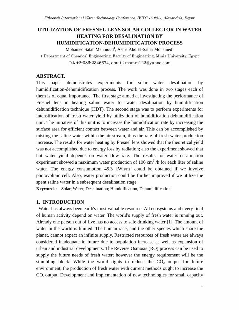
2. METHODOLOGY Figure 1a illustrates a schematic diagram of the experimental setup. The FL shown in
Fig. 1b consists of acrylic sheet with concentric grooves 0.5×0.7 m with focal length
of 0.5m. The lens was fixed facing south with a tilt angle of 28o in summer season. The saline water passes through pipe of 0.2 m length and ID 0.75 in. The water storage
Fifteenth International Water Technology Conference, IWTC-15 2011, Alexandria, Egypt
4
tank is made from steel and sealed by glass wool in order to reduce the heat loss; also it is supplied with electrical heater to adjust the temperature of hot saline water to the desired feed temperature. As indicated in Fig. 1a, water pass with a different flow rates once through the heating pipe where it is heated by the focused solar energy. Once the
water temperature reaches the desired starting temperature, water is directed to the humidification unit. The arrangement of humidification dehumidification unit is shown in Fig. 1c. It
consists of a cuboid (0.8× 0.5×0.5 m) constructed of galvanized steel of 0.001m
thickness lined with plastic sheet. The air is inserted to the unit by fan with 0.25 m diameter mounted on one face of the tank. The velocity of inlet air is measured by using hot wire anemometer and the average velocity of inlet air can be calculated by
(1)
The average flow rate was 0.11 m3/s and average air velocity of 4.5 m/s. The vapor content difference is defined as
ΔH= Hout – Hin (2) where Hin, Hout are the inlet outlet humidity of the unit.
The humidification efficiency of the unit is given by
100 (3)
On the opposite face, a condenser is fixed with length, width and thickness of 0.3, 0.6 and 0.3 m respectively. The fresh water resulting from treatment process is collected through a header channel mounted below the condenser. The rotating disc sprayer is placed inside the unit and 0.2 m in front of the fan to perform the misting of saline
water to get droplets of about 0.001 m. The unit has discharge weir for recycling of miscarried water to the storage tank, and is covered by transparent plastic cover to keep the air inside.

Fiftee
The consuppliedatomic ab
The temof each p
3. THE The heat and
liquid [1abscissasarrows rrepresen
the humias shown
vapor an
eenth Interna
Fig. 1: (
ncentration d by AZ Inbsorption sp
mperature ofpart of the u
EORETICinteraction
d diffusion
12]. In Fig. s and temprepresent th
nt the flow o
idification pn in Fig 2(a
nd heat tra
ational Water
(b)
(a) Setup of
of salt wanstrument Cpectrophotom
f hot feed wunit and the
CAL CONS between uof vapor th
2, distanceperatures anhe diffusionof heat (bot
process, thea), here both
ansfer (and
r Technology
f the experim
as measuredCorp. The hmeter (ELIC
water and aie water and
SIDERATunsaturated hrough the
es measurednd humilitin of the vath latent an
e temperatuh Ti and Hi d the direct
Conference,
(a)
ment, (b) Fr
d by AZ 8
heavy metaCO SL 176)
ir and the hair mass flo
TION gas and ligas at the
d perpendices as ordinapor througnd sensible)
ure of the li
i is greater t
tion of tem
IWTC-15 20
(c)
resnel lens, (
86555 labor
al concentraat 324.7 nm
humidity atow rates are
iquid is coninterface b
cular to the nates. In bogh the gas ) through ga
iquid is higthan Ty and mperature a
011, Alexandr
(c) HD Unit
ratory benc
ation was mm wave leng
t the inlet ae measured
ntrolled bybetween the
interface aoth Figuresphase, andas and liqu
gher than th H, and thu
and humidi
ria, Egypt
t.
ch top met
measured bth for coppe
and the outld.
y the flow oe gas and th
are plotted as, the broked full arrowid phases. I
hat of the gaus the flow o
ity gradien
5
er
by er.
let
of he
as en ws In
as of
nt)

Fifteenth International Water Technology Conference, IWTC-15 2011, Alexandria, Egypt
6
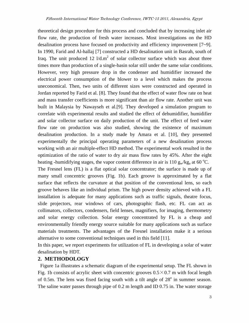
commence from liquid to vapor. The liquid is being cooled by both evaporation and by transfer of sensible heat, the humidity and temperature of the gas decrease in the direction from the interface to the gas, and the temperature drop Tx- Ti through the liquid must be sufficient to give a heat transfer rate high enough to account for both
heat items. Conditions at one point in dehumidification process are shown in Fig 2(b), here H is greater than Hi, and therefore vapor must diffuse to the interface. Science Ti and Hi
represent saturated gas, Ty must be greater than Ti; otherwise the bulk of the gas would
be supersaturated with vapor. These reasoning lead to conclusion that vapor can be removed from unsaturated gas by direct contact with sufficiently cold liquids without first bringing the bulk of gas to saturation.
Fig. 2: (a) Conditions in variable temperature humidifier. (b) Conditions in
dehumidifier [12].
At any time, the water is exiting from its surface as vapor. Meanwhile, the vapor
condenses to water from the air. If the humidity increases, the amount of vapor coming back
to water increases. Such evaporation and condensation through water surface balance at the
humidity of 100%.
The rate of evaporation of water from solution depends on the geometry of contact between water and air. In the case of spherical water droplets sprayed in air stream, the rate of evaporation depends on the particle diameter as follows [13]
` (4)
It is notable that decreasing particle diameter will increase the mass transfer coefficient and accordingly the rate of evaporation will increase. Therefore, the
recommended way for efficient evaporation is to produce very fine droplets, which fly very fast through dry air. We can estimate the condition by boundary layer theory.

Fifteenth International Water Technology Conference, IWTC-15 2011, Alexandria, Egypt
7
The rate of mass transfer (NA) for flow of air across water droplets is obtained by: [13] (5)
The mass transfer coefficient (kc) can be obtained from the following formula for Reynolds number (Re) range (1-480000) and Schmidt number (Sc) of (0.6-2.7) [13]
2 0.552 . / (6) We can compute the evaporation rate (W) by using NA
(7)
⁄
From this formula, we conclude that if water droplet of 0.001m radius flies with speed 10 m/s, it completely evaporates within 1 second.
In order to increase the efficiency of humidification process, heating the feed water is necessary to boost heat transfer and fortify evaporation. The theoretical calculation of the water exit temperature from solar heating system is calculated with the aid of energy balance in the spot to be heated by FL. From sun-earth geometry,
(8)
Where F is the length power, F =f / Dlens, f is the focal length (m), Dlens is the diameter of the FL (m), L is the length from sun to earth (1.5×10¹¹ m), Rsun is the radius of sun
(6.96×10⁸ m), Ispot is the spot intensity (W/m2), Io is the incidence solar intensity (~ 800 W/m2) with temperature of 1000 K. The spot intensity is 46.4×10³ kW/m2, for spot of 2 cm diameter (3.14×10⁻⁴ m2) the incident power is 14.59 kW. If we consider 10% energy loss due to convection and radiation and if the efficiency of energy
transfer to water is approximately 80%. The power available for water heating will be 10.2 kW, thus for one second the amount of water heated to 80 oC is 40.6 g or 40.6 ml/s (2.4 l/min).
4. RESULTS AND DISCUSSION Table 1 shows the variation of temperature with flow rate for heating water by FL solar collector. The findings indicated that it was not possible to confirm theoretical flow rate calculated before. The solar heating system was almost insufficient to supply enough water continuously to the HD experiment with the desired temperature. That
was mainly referred to the poor heat transfer from the hot pipe to the water flowing inside it, also there are uncertainties about the power loss due to reflection and radiation, moreover, there are other unaccounted solar intensity losses such as the manual solar tracking system of the FL, and collection efficiency of FL material. It is
also noticeable that the FL solar collector available for this experiment was relatively small [< 1 m2]. In order to heat water to the desired temperature for HD experiment, it
o
2
2spot I
R
LIF
Sun

Fifteenth International Water Technology Conference, IWTC-15 2011, Alexandria, Egypt
8
was necessary to use electric heater. However, the solar water heating could be further improved by increasing the area of solar water heating system [14] or utilization of more efficient scheme to heat water such as linear Fresnel lens [15]. Table 1: Variation of temperature with flow rate for heating water by FL solar collector
on 20th July, 2010, at Minia Governorate (latitude 28o N), Egypt
In the second stage, water desalination process was investigated. In order to check the quality of the fresh water, a preliminary experiment was made; the feed saline
water has temperature of 60 oC and average flow rate of 100 l/h. The initial concentration of salt in water was 35 g/l relatively close to the value of average water salinity in the sea [16]. The result showed fresh water with salinity of 0.5 g/l, similar to corresponding value of the water quality standards [17]. Next, we checked the
possibility of heavy metal removal by HDT. Copper ion was chosen to represent heavy metal contaminant in water. The feed saline water, with the same temperature and flow rate as aforementioned, was prepared with initial copper sulfate concentration of 100 mg/l. The results showed a concentration of 0 mg/l. From these data, it is evident that
our method could be used for production of water with acceptable quality. Theoretically, the more dominant parameter is inlet water temperature. Figure 3 shows the effect of inlet water temperature on both percentage humidity of carrier air and outlet water flow rate. It was evident that increasing water temperature increases both
the air humidity and outlet water flow rate. The maximum water flow rate obtained was 2.65 l/h at inlet water temperature of 85 oC. If we consider initial saline water of 25 l and average experiment duration of 15 min, the maximum water production will be 106 cm3 /h for each liter of saline water.
Temp. of water after
heating pipe, oC
Pipe preheating
Period, min
Feed water flow rate,
l/min
Feed water
temperature, oC.
49 30 1 35
50 30 1 36
56 30 0.5 36
63 30 0.5 37
66 30 0.25 37
73 30 0.25 38
76 45 0.25 37

Fifteenth International Water Technology Conference, IWTC-15 2011, Alexandria, Egypt
9
Fig 3: Effect of inlet water temperature on the percentage of humidity of carrier air and
on the output freshwater volumetric flow rate at sprayer speed of 2200 rpm.
Table 2 shows the water temperature and air humidity at different places of the experimental unit. It can be noticed that the temperature of miscarried water is
sufficiently high to be further used. In this experiment we recycled this water to be reused, however this design could be further enhanced by introducing miscarried water to second humidification stage to increase the fresh water yield, this will be concidered in the subsequent paper. Furthermore, it also appeared that the humidity of the outlet
air is higher than the inlet air implyig that the efficiency of the condenser is inadiquate. Table 2: Water temperature and air humidity at different places of the experiment
Exp. No Tw, in, oC Tw, out, oC ΔT Ha, in Ha, out ΔH η Ha, c
1 60 40 20 33 86 53 79 74
2 70 46 24 37 90 53 84.1 80
3 80 49 31 33 92 59 88.1 82
4 85 53 32 36 93 57 89 81
5 95 60 38 33 98 65 97 84
* Tw, in = temperature of inlet water, Tw, out = temperature of miscarried water, Ha, in = humidity of air entering the humidification unit at 30 oC, Ha, out = humidity after humidification step, Ha, c = humidity of air after the condenser.
The energy consumption per liter of fresh water is calculated based on the maximum rate of desalination at 85oC. The power consumption for fan is Q Fan = 30 W, for the spray atomizer Q atomizer motor = 15 W and for water pump Qpump= 75 W. For fresh water with flow rate v` = 2.65 * 10 -3 m3/h
∆ (9)
Where T1=85 °C, T2 =56°C. Thus Qw = 321.5 kJ/h.
Total energy required / hour [Qtot( kJ/h )= Qw + Q Fan+ Q atomizer + Qpump]= 753.5 kJ/h Energy per m3 = 79 kW.h/m3
50
60
70
80
90
100
110
0
1
2
3
4
50 60 70 80 90 100
% H
umid
ity
Out
put w
ater
vou
lme,
l/h.
Temperature, °C
Fresh water flow rate
% Humidity

Fifteenth International Water Technology Conference, IWTC-15 2011, Alexandria, Egypt
10
If we omit the energy for water heating, the total energy will be 45.3 kwh/m3. This energy could be supplied by photovoltaic cell. However, this energy still higher than energy required for desalination by reverse osmosis system [2.5-7 kWh/m3] [18]. It should be emphasized that there are two points must be considered for increasing the
efficiency and yield of our system, first is the temperature of miscarried water is high enough to be introduced to a second stage of the humidification system [15690 kJ/hr with miscarried water in case of T= 56 oC], second is the humidity of air after the condenser still higher than that of inlet air. For example according to Table 2, the
humidity of air for the maximum production experiment was 93% before condenser and 81% after condensation with air temperature of 30 oC. From humidity chart, the amount of water corresponds to 93% and 81% are 26 gw/kgair and 20 gw/kgair respectively. This indicates that the air with volumetric flow rate of 0.11 m3/s and with
humidity of 93% will carry 12.36 kg water per hour while after the condenser the air carries 9.5 kg water per hour. Thus the condenser efficiency is 23% and additional condensation steps are required to maximize the yield of fresh water from this unit.
5. CONCLUSION We have presented a study of the possibilities of the use of Fresnel lenses in the development
of water desalination system by humidification-dehumidification technique. The results for
water heating by Fresnel lens showed that the theoretical yield was not accomplished due to
energy loss by radiation; also the experiment showed that hot water yield depends on water
flow rate. The results for water desalination experiment showed that water with initial
concentration of salt of 35 g/l gave fresh water with salinity of 0.5 g/l, also, the HD system
could totally eliminate copper ion from contaminated feed water with initial concentration of
100 mg/l. The maximum water flow rate obtained was 2.65 l/h at inlet water temperature of
85 oC. The energy consumption per liter of fresh water is calculated at 85oC to be 45.3
kW.hr/m3, which is higher than energy required for desalination by reverse osmosis system
[2.5-7 kWh/m3]. The temperature of miscarried water is high enough to be introduced to a
second stage of the humidification system [15690 kJ/hr with miscarried water in case of T=
56 oC]. Also, the condenser efficiency is 23% and additional condensation steps are required
to maximize the yield of fresh water from this unit.
List of Symbols Aw = the area of water drop, m2
Atot = the total area of the air flow, m2
DAB = the diffusion constant, m2/s Dp= water drop diameter, m
Dlens = the diameter of the FL, m
F = the length power, m
f = the focal length, m

Fifteenth International Water Technology Conference, IWTC-15 2011, Alexandria, Egypt
11
Hi = humidity at interface
H = humidity of bulk of gas
Hsat = the outlet saturation humidity
Io = the incidence solar intensity, (~ 1000 W/m2)
Ispot = the spot intensity, (W/m2)
L = the length from sun to earth, (1.5×10¹¹m)
NA = the rate of mass transfer per unit time and unit area, kg/m2 s
kc=mass transfer coefficient, m/s
kG= mass transfer coefficient for gases, kg mol/(s m2Pa)
R = the droplet radius, m
Rsun = the radius of sun, (6.96×10⁸ m)
Re = Reynolds number,
Sc= Schmidt number
Sh= Sherwood number,
Tx = temperature of the bulk of liquid, oC
Ti = temperature at interface, oC
Ty= temperature of bulk of gas, oC
uo = average velocity of the air, m/s
Vw = is the volume of water drop, m3
W= rate of evaporation, kg/s
μ= water viscosity, g/cm s
ρw = the density of water, kg/m3
ηhu= humidification efficiency
References [1] Dave Palmer, Chehalis River Council,
http://www.crcwater.org/issues5/19980827whycare.html, retrieved August 2009
[2] Egypt State Information Service,
http://www.sis.gov.eg/En/Politics/Foreign/issues/egyptwater.htm, retrieved June 2010
[3] Mohammad Al-Sahali, Hisham M. Ettouney, “Humidification dehumidification
desalination process: Design and performance evaluation”, Chemical Engineering Journal
143 (2008) 257–264.
[4] K. Bourouni, M.T. Chaibi, L. Tadrist, “Water desalination by humidification and
dehumidification of air: State of the art”, Desalination, 137 (2001) 167–176.
[5] M.F.A. Goosen, S.S. Sablani,W.H. Shayya, C. Paton, H. Al-Hinai, “‘Thermodynamic and
Economic Considerations in Solar Desalination”, Desalination, 129 (2000), 63–89.

Fifteenth International Water Technology Conference, IWTC-15 2011, Alexandria, Egypt
12
[6] M.A. Younis, M.A. Darwish and F. Juwayhel, “Experimental and theoretical study of a
humidification-dehumidification desalting system”, Desalination, 94 (1993) 11-24.
[7] Said Al-Hallaj, M.M. Farid and A.R. Tamimi, “Solar desalination with a
humidification-dehumidification cycle: performance of the unit”, Desalination, 120 (1998)
273–280.
[8] M.M. Farid, N.K. Nawayseh, S. Al-Hallaj and A.R. Tamimi, “Solar desalination with
humidification dehumidification process: Studies of heat and mass transfer, Proc.”,
Conference: SOLAR 95, Hobart, Tasmania, 1995, pp. 293–306.
[9] N.K. Nawayseh, M.M. Farid, S. AL-Hallaj and A.R. Tamimi, “Solar desalination based on
humidification process—I. Evaluating the heat and mass transfer coefficients”, Energy
Conv. Mgmt., 40 (1999), 1423–1439.
[10] Amara MB, Houcine I, Guizani A, Mfialej M., “Experimental study of a multiple-effect
humidification solar desalination technique”, Desalination, 170, ( 2004), 209–221.
[11] CRISTINA SIERRA, ALFONSO J. VA´ ZQUEZ, “High solar energy concentration with
a Fresnel lens”, J. of Materials Science, 40 (2005) 1339 – 1343.
[12] McCabe, W. L., Smith, J. C., and Harriott, P., “Unit Operation of Chemical
Engineering”, McGraw- Hill, New York, 5th Edition (1993), pp 753-762
[13] J.R. Welthy, C. E. Wicks, and R. E. Wilson, “Fundamentals of Momentum, Heat, and
Mass Transfer”, John Wiley & Sons Inc., 3rd edition, (1984), pp 650-651
[14] Joshua FOLARANMI, “Design, Construction and Testing of a Parabolic Solar Steam
Generator”, Leonardo Electronic J. of Practices & Technologies, 14, (2009), 115-133
[15] H. Zhai, Y.J. Dai *, J.Y. Wu, R.Z. Wang, L.Y. Zhang, “Experimental investigation and
analysis on a concentrating solar collector using linear Fresnel lens”, Energy
Conv.Mgmt., 51, (2010), 48–55
[16] R Nave, http://hyperphysics.phy-astr.gsu.edu/hbase/chemical/seawater.html, retrieved
June 2010
[17] Nicholas P. Cheremisinof, “handbook of water and wastewater treatment technologies”,
Butterworth Heinemann, (2002), p 26.
[18] AMY K. ZANDER, et al, “Desalination, a National Perspective”, National Academies
Press, (2008), pp. 59-108; Internet, http://www.nap.edu.


![CONTENTS Manual.pdf · 2014. 9. 19. · 14,G76 minimal cutting depth(10um) [X axis radius] 15,G76 finish turn remaining(10um) 16,X program mode [1 mean Radius,0 mean Diamete] 17,Running](https://img.dokumen.tips/doc/110x75/607b7ec87866d919955418fa/contents-2014-9-19-14g76-minimal-cutting-depth10um-x-axis-radius-15g76.jpg)


