Embed Size (px)
Citation preview

Utilities Management Strategy
M4-M5 Link Mainline Tunnels December 2018

2 | M4-M5 Link Mainline Tunnels: Utilities Management Strategy UNCONTROLLED WHEN PRINTED
THIS PAGE LEFT INTENTIONALLY BLANK


4 | M4-M5 Link Mainline Tunnels: Utilities Management Strategy UNCONTROLLED WHEN PRINTED
Contents
Glossary/ Abbreviations ..................................................................................................... 6
1 Introduction ................................................................................................................... 8
1.1 Context ................................................................................................................... 8
1.2 Background and Project Description ....................................................................... 8
1.2.1 Project background ...................................................................................... 8
1.2.2 Project description ....................................................................................... 8
1.3 Scope ................................................................................................................... 10
1.4 Purpose ................................................................................................................ 11
1.5 Consultation .......................................................................................................... 12
2 Environmental requirements ...................................................................................... 13
2.1 Relevant legislation and guidelines ....................................................................... 13
2.1.1 Legislation ................................................................................................. 13
2.1.2 Guidelines ................................................................................................. 13
2.2 Ministers Conditions of Approval ........................................................................... 13
2.3 Environmental Management Measures ................................................................. 15
3 Approach to Proposed Utility Works ......................................................................... 17
3.1 EIS Areas of Interest ............................................................................................. 17
3.2 Identifying utility conflicts ...................................................................................... 17
3.3 Unknown utilities ................................................................................................... 19
3.4 Treatment approach to utility services ................................................................... 20
3.5 Utility works process ............................................................................................. 20
3.6 Investigations works .............................................................................................. 21
3.7 Low Impact Utilities Works .................................................................................... 22
3.8 Options assessment ............................................................................................. 22
4 Project Utilities Works ................................................................................................ 24
4.1 Wattle Street ......................................................................................................... 24
4.2 Northcote Street and PRE&W ............................................................................... 24
4.3 PBR ...................................................................................................................... 25
4.4 Campbell Road and St Peters interchange, St Peters ........................................... 25
4.5 Construction Ancillary Facility – White Bay ........................................................... 26
4.6 Mainline Tunnels ................................................................................................... 26
4.6.1 Sydney Water utility services ..................................................................... 26
4.6.2 Ausgrid utility services ............................................................................... 26
4.6.3 Jemena utility services ............................................................................... 27

5 | M4-M5 Link Mainline Tunnels: Utilities Management Strategy UNCONTROLLED WHEN PRINTED
4.7 Proposed drainage infrastructure .......................................................................... 27
4.7.1 Upgrade of existing road drainage infrastructure within the Project footprint 27
4.7.2 Drainage works outside Project footprint.................................................... 27
4.8 Construction Power Supply ................................................................................... 27
4.8.1 Construction Power – Haberfield/Ashfield sites.......................................... 28
4.8.2 Construction Power – PBR ........................................................................ 28
4.8.3 Construction Power – Campbell Road ....................................................... 28
4.9 Operational Power Supply .................................................................................... 28
4.9.1 Estimated power demand .......................................................................... 29
4.9.2 Power supply connection locations ............................................................ 29
5 Environmental Management ....................................................................................... 30
5.1 Potential Environmental Impacts ........................................................................... 30
5.1.1 Electric and Magnetic Fields ...................................................................... 32
5.1.2 Cumulative Impacts ................................................................................... 32
5.2 Management Measures ........................................................................................ 33
6 Responsibilities ........................................................................................................... 34
6.1 Community and Stakeholder Consultation ............................................................ 34
6.2 Utility Coordination Manager ................................................................................. 34
6.3 Environment and Sustainability Manager .............................................................. 35
Appendix A ........................................................................................................................ 36
1 Low Impact Works Definition ..................................................................................... 37
1.1 Noise Impacts ....................................................................................................... 37
1.2 Traffic and Access Impacts ................................................................................... 41
1.3 Residential Parking ............................................................................................... 41
1.4 Biodiversity ........................................................................................................... 42
1.5 Heritage ................................................................................................................ 42
1.6 Dust ...................................................................................................................... 42
1.7 Surface Water Management ................................................................................. 42
1.8 Lighting Impacts .................................................................................................... 42
2 Low Impact Works Mitigation Measures .................................................................... 43
Appendix B ........................................................................................................................ 46
Appendix C ........................................................................................................................ 47

6 | M4-M5 Link Mainline Tunnels: Utilities Management Strategy UNCONTROLLED WHEN PRINTED
Glossary/ Abbreviations
Abbreviations Expanded text
AECOM AECOM Australia Pty Ltd
AHD Australian Height Datum
AHIMS Aboriginal Heritage Information Management System
CBD Central Business District
CCS Community Communications Strategy
CEMP Construction Environmental Management Plan
CLM Act Contaminated Land Management Act 1997
CNVG Roads and Maritime Construction Noise and Vibration Guideline
CoA Conditions of Approval
CSELR CBD and South East Light Rail
CSSI Critical State Significant Infrastructure
DBYD Dial-Before-You-Dig
DECCW Department of Environment and Climate Change
DPE NSW Department of Planning and Environment
DPI NSW Department of Primary Industries
EIS Environmental Impact Statement
EMF Electric and magnetic fields
EPA NSW Environment Protection Authority
EP&A Act Environmental Planning and Assessment Act 1979
GPR Ground Penetrating Radar
GPS Global Positioning System
HV High voltage
HVC High voltage customer
ICNG Interim Construction Noise Guideline

7 | M4-M5 Link Mainline Tunnels: Utilities Management Strategy UNCONTROLLED WHEN PRINTED
Abbreviations Expanded text
LEP Local environmental plan
LSBJV Lendlease Samsung Bouygues Joint Venture
LV Low voltage
MVA Mega Volt Amp
NBN National Broadband Network
NCA Noise catchment area
NDD Non-Destructive Digging
NML Noise Management Level
NSW New South Wales
OEH Office of Environment and Heritage
PBR Pyrmont Bridge Road tunnel site
PRE&W Parramatta Road East civil site and Parramatta Road West civil site
REMM Revised Environmental Management Measure
RL Reduced level
Roads and Maritime NSW Roads and Maritime Services
ROL Road Occupancy Licence
SEMP Site Establishment Management Plan
SL Street Light/Lighting
SMC Sydney Motorway Corporation
SPIR Submissions and Preferred Infrastructure Report
SUI Subsurface utility investigation
STS Sub Transmission Substation
TMC Traffic Management Centre
UCM Utility Coordination Manager
ZS Zone Substation

8 | M4-M5 Link Mainline Tunnels: Utilities Management Strategy UNCONTROLLED WHEN PRINTED
1 Introduction
1.1 Context This Utility Management Strategy (the Strategy) forms part of the approval documentation for WestConnex M4-M5 Link Mainline Tunnels (the Project).
This Strategy has been prepared to address the requirements of the Minister’s Conditions of Approval (CoA), the WestConnex M4-M5 Link Environmental Impact Statement (EIS), the revised environmental management measures (REMM) listed in the WestConnex M4-M5 Link Submissions and Preferred Infrastructure Report (SPIR) and all applicable guidance and legislation.
1.2 Background and Project Description
1.2.1 Project background The M4-M5 Link EIS (AECOM 2017) assessed the impacts of construction and operation of the Project. The EIS included a description of the construction ancillary facilities, within Chapter 6.5, and assessed the potential impacts in relation to the ancillary facilities in Chapters 8 – 26.
The EIS identified the potential for a range minor impacts associated with ancillary facilities (and therefore site establishment works). However, it concluded any potential impacts could be managed by standard mitigation and management measures.
1.2.2 Project description The WestConnex M4-M5 Link project is being constructed in two stages:
• Stage 1 (the Project and subject of this document): M4-M5 Link Mainline tunnels
• Stage 2: Rozelle Interchange.
Sydney Motorway Corporation (SMC) has engaged Lendlease Samsung Bouygues Joint Venture (LSBJV) to design and construct Stage 1 of the project. The key features of the Mainline tunnel Project include:
• Twin mainline motorway tunnels between the M4 East at Haberfield and the New M5 at St Peters. Each tunnel would be around 7.5 kilometres long and would generally accommodate up to four lanes of traffic in each direction
• Connections of the mainline tunnels to the M4 East project, comprising:
A tunnel-to-tunnel connection to the M4 East mainline stub tunnels east of Parramatta Road near Alt Street at Haberfield
Entry and exit ramp connections between the mainline tunnels and the Wattle Street interchange at Haberfield (which is currently being constructed as part of the M4 East project)
Minor physical integration works with the surface road network at the Wattle Street interchange including road pavement and line marking
• Connections of the mainline tunnels to the New M5 project, comprising:

9 | M4-M5 Link Mainline Tunnels: Utilities Management Strategy UNCONTROLLED WHEN PRINTED
A tunnel-to-tunnel connection to the New M5 mainline stub tunnels north of the Princes Highway near the intersection of Mary Street and Bakers Lane at St Peters
Entry and exit ramp connections between the mainline tunnels and the St Peters interchange at St Peters (which is currently being constructed as part of the New M5 project)
Minor physical integration works with the surface road network at the St Peters interchange including road pavement and line marking
• Construction of tunnel stubs to provide for future underground connection of the mainline tunnels to the Rozelle Interchange
• A motorway operations complex at St Peters (Campbell Road) (MOC5). The types of facilities that would be contained within the motorway operations complexes would include substations, water treatment plants, ventilation facilities and outlets (the Campbell Road ventilation facility), offices, on-site storage and parking for employees
• Tunnel ventilation systems, including ventilation supply and exhaust facilities, ventilation fans, ventilation outlets and ventilation tunnels
• A new ventilation facility located at the Campbell Road ventilation facility at St Peters
• Fitout (mechanical and electrical) of part of the Parramatta Road ventilation facility at Haberfield (which is currently being constructed as part of M4 East project) for use by the M4-M5 Link project
• Drainage infrastructure to collect surface and groundwater for treatment at dedicated facilities
• Water treatment would occur at the operational water treatment facility at the Campbell Road motorway operations complex
• Ancillary infrastructure and operational facilities for electronic tolling and traffic control and signage (including electronic signage)
• Emergency access and evacuation facilities, including pedestrian and vehicular cross and long passages and fire and life safety systems
• Utility works, including protection and/or adjustment of existing utilities, removal of redundant utilities and installation of new utilities
• Temporary construction ancillary facilities to facilitate construction of the Project would be required at the following locations:
Northcote Street civil and tunnel site (C3a), Haberfield (Northcote Street)
Haberfield civil site (C2b), Haberfield (PRVF)
Parramatta Road East civil site (C3b), Haberfield (PRE) and Parramatta Road West civil site (C1b), Ashfield (PRW) (or PRE&W combined)
Wattle Street civil and tunnel site (C1a), Haberfield (Wattle Street)
Pyrmont Bridge Road tunnel site (C9), Camperdown/Annandale (PBR)
Campbell Road civil and tunnel site (C10), St Peters (Campbell Road)
White Bay civil site (C11), Rozelle. (White Bay).
An overview of the Project footprint and ancillary facilities is presented in the Construction and Environmental Management Plan (CEMP) and Site Establishment Management Plan (SEMP). Further detail of the Project description is presented in Section 1.3 of the CEMP.
10 | M4-M5 Link Mainline Tunnels: Utilities Management Strategy UNCONTROLLED WHEN PRINTED
1.3 Scope The scope of this Plan is to describe how Lendlease Samsung Bouygues Joint Venture (LSBJV) propose to manage all utilities works for the Project.
Relocation or protection works will be carried out to utilities that cannot be avoided either being directly impacted or have the potential to be impacted by the works. Additional temporary and operational power supply connections and new drainage infrastructure would be required within and outside of the Project footprint to service the construction and operation of the Project.
The EIS identifies (Section 6.3) that the utility works required to support the Project would occur both within and outside the Project footprint; identified in combination in Appendix F of the EIS as ‘Areas of Interest’. Works within the Project boundary are assessed within the EIS, while those outside the Project Boundary have been subject to environmental assessment as part of the EIS Appendix F. In combination, these have been approved as part of the Project and are referenced as ‘Areas of Interest’ in this document.
Works required outside ‘Areas of Interest’ required as a result of detailed design, would be subject to further environmental assessment as discussed in Section 3.1.
As per CoA E140, utility works that are not low impact are considered ‘construction’ and appropriate management measures are included in the approved CEMP. Prior to that time, any ‘low impact’ works may be undertaken under the management of this Strategy.
As such, the scope of this Strategy is to:
• Define the scope and role of the Utilities Coordination Manager (refer to Section 6.2)
• Identify all utility installation, protection, relocations, adjustments and new connections (defined as utility works) which are proposed for the entirety of the Project
• Provide a definition and identification of ‘low impact’ utilities works (refer to Appendix A) and relevant environmental management measures to be implemented for undertaking these works prior to the commencement of construction
• Identification of any utility works that are required outside of the Project footprint which differ from the ‘Areas of Interest’ (refer to Appendix A) as identified in the EIS Appendix F, and the framework for how these utility works would be assessed and managed. This includes requirements for stakeholder and community consultation, environmental constraints analysis and environmental risk assessment.
The utility services which have been considered in this Strategy include: communications, gas, electricity (including Ausgrid and Sydney Trains infrastructure), water, sewerage and drainage.

11 | M4-M5 Link Mainline Tunnels: Utilities Management Strategy UNCONTROLLED WHEN PRINTED
1.4 Purpose The information contained in this Strategy regarding existing utility services and proposed utility works is based on:
• Utility investigations conducted to date
• Preliminary discussions with utility service providers during the EIS phase
• The proposed LSBJV concept design for the Project
• CoA and REMM requirements included in Sections 2.2 and 2.3.
This Strategy establishes a process for managing utility works associated with the Project, including arrangements for ongoing stakeholder and community consultation, and environmental constraints analysis and environmental risk assessment during the detailed design phase for any utility works that are required outside of the Project footprint which differ from the ‘Areas of Interest’ as identified in the EIS Appendix F.
The purpose of this Strategy is:
• To provide a definition of low impact utility works (refer to Appendix A) and identify scope of required low impact utility works
• To outline the utility works currently proposed as part of the Project including providing a mechanism for the classification of ‘low impact’ utilities works
• To outline the options being considered for the provision of construction power supply and permanent operational power supply for the Project
• To outline the options being considered for the upgrade of existing drainage infrastructure or provision of new drainage infrastructure for the Project
• To provide an overview of how the utility works, including power supply and drainage works would be carried out
• To assess the range of potential environmental impacts associated with utility works, including cumulative impacts
• To identify and assess potential impacts to existing utility assets
• To provide an environmental constraints analysis for areas outside of the Project footprint where utility works, such as construction and operational power supply connections, are likely to be required
• To outline a range of mitigation measures which would be applied to minimise the potential environmental impacts
• To outline a process for how utility works that are not assessed as part of the EIS would be managed (refer to Section 3.1), including requirements for:
Obtaining agreements with utility service providers
Effective co-ordination of utility adjustment works
Consideration of route options where appropriate
Undertaking environmental constraints analysis and risk assessment to confirm potential environmental impacts and appropriate management measures
Stakeholder and community consultation and notification
• To provide an overview of key responsibilities of the Utilities Coordination Manager in relation to this Strategy.

12 | M4-M5 Link Mainline Tunnels: Utilities Management Strategy UNCONTROLLED WHEN PRINTED
This Strategy will be submitted to the Secretary for approval at least one month prior to the commencement of low impact utility works.
1.5 Consultation Utility investigations relating to the Project will be undertaken with consideration of the following utility service providers:
• Ausgrid
• Sydney Water
• Sydney Trains
• Jemena
• Telecommunications (including, but not limited to Telstra, Optus / Uecomm, National Broadband Network (NBN), NextGen, Vocus, AARNet, Pipe Networks etc).
Consultation with utility service providers will continue for the duration of the Project as required.
Community and stakeholder consultation and notification with regard to utilities works will be undertaken in accordance with the Community Communication Strategy (CCS) prepared in accordance with CoA B1.

13 | M4-M5 Link Mainline Tunnels: Utilities Management Strategy UNCONTROLLED WHEN PRINTED
2 Environmental requirements
2.1 Relevant legislation and guidelines
2.1.1 Legislation Legislation relevant to utilities construction includes:
• Environmental Planning and Assessment Act 1979 (NSW) (EP&A Act)
• State Environmental Planning Policy (Infrastructure) 2007 (NSW)
• Protection of the Environment Operations Act 1997 (NSW)
• Biodiversity Conservation Act 2016 (NSW)
• Biosecurity Act 2015 (NSW)
• National Parks and Wildlife Act 1974 (NSW)
• Heritage Act 1977 (NSW)
• Contaminated Land Management Act 1997 (NSW) (CLM Act)
• Coastal Protection Act 1979 (NSW)
• Fisheries Management Act 1994 (NSW)
• Water Act 1912 (NSW)
• Water Management Act 2000 (NSW);
• Roads Act 1993 (NSW)
• Electricity Supply Act 1995 (NSW)
• Gas Supply Act 1996 (NSW)
• Telecommunications Act 1997 (Commonwealth)
• Pipelines Act 1967 (NSW).
Additional legislation relevant to environmental management is detailed in the Project CEMP.
2.1.2 Guidelines Utility authority applicable standards, specifications, guidelines and policy documents are to be considered in conjunction with this Strategy.
2.2 Ministers Conditions of Approval The CoA relevant to this Strategy are listed in Table 2-1 below. A cross reference is also included to indicate where the condition is addressed in this Strategy or other Project management documents.

14 | M4-M5 Link Mainline Tunnels: Utilities Management Strategy UNCONTROLLED WHEN PRINTED
Table 2-1 Ministers Conditions of Approval
CoA No. Condition Requirements Document Reference
B6 A Public Liaison Officer(s) must be appointed for construction ancillary facility(s) and for utility works to assist the public with questions and complaints they may have at any time during construction. The Public Liaison Officer(s) must be available at all times that works are occurring.
Section 6.1
E78 All works undertaken for the delivery of the CSSI, including those undertaken by third parties, must be coordinated to ensure respite periods are provided. The Proponent must:
(a) reschedule any works to provide respite to impacted noise sensitive receivers so that the respite is achieved in accordance with Condition E76, or
(b) consider the provision of alternative respite or mitigation to impacted noise sensitive receivers; and
(c) provide documentary evidence to the AA in support of any decision made by the Proponent in relation to respite or mitigation.
6.2
E140 A Utilities Management Strategy must be prepared and implemented for all utility works. The Strategy must identify how utility works will be defined and managed.
The Utilities Management Strategy must include:
This Document
(a) a definition of low impact utility work. The definition must consider parameters including, but not limited to, type of works, duration of works, hours of works, noise impacts, and traffic and access impacts;
Section 3.7
Appendix A
(b) the functions of the Utility Coordination Manager as required by Condition E141;
Section 6.2
(c) a description of all utility works to be undertaken, including low impact utility works and how they meet the definition in subclause (a); and
Section 4
(d) the management measures that will be implemented to manage dust, noise, traffic, access and lighting impacts associated with low impact utility works.
Appendix A
The Utilities Management Strategy must be submitted to the Secretary for approval at least one (1) month prior to the commencement of low impact utility works.
Section 1.4

15 | M4-M5 Link Mainline Tunnels: Utilities Management Strategy UNCONTROLLED WHEN PRINTED
CoA No. Condition Requirements Document Reference
E141 A Utility Coordination Manager must be appointed for the duration of the Critical State Significant Infrastructure (CSSI) works. The role of the Utility Coordination Manager must include, but not be limited to:
(a) the management and coordination of all utility works associated with the delivery of the CSSI, to ensure respite is provided to the community, as required under Condition E75;
(b) providing advice to the Public Liaison Officer(s), regarding upcoming utility works, including the scope of the works and responsibility for the works; and
(c) investigating complaints received from the Community Complaints Mediator or the Public Liaison Officer(s), relating to utility works, and providing a response to the Community Complaints Mediator or Public Liaison Officer(s).
Section 6.2
2.3 Environmental Management Measures The REMMs as listed in the SPIR, which are relevant to this Strategy are listed in Table 2-2 below. A cross reference is also included to indicate where the condition is addressed in this Strategy or other Project management documents.
Table 2-2 Revised Environmental Management Measures
REMM No.
Condition Requirements Document Reference
PL12 Interface agreements will be entered into with the owners of infrastructure and utility services likely to be impacted by construction of the Project. The agreements will likely identify:
- Minimum separation distances and appropriate settlement criteria for utility infrastructure
- Settlement monitoring requirements during construction
- Contingency actions in the event that settlement limits are exceeded.
Section 4
PL14 The Utilities Management Strategy (Appendix F of the EIS) will be implemented.
This Strategy
FD12 Where drainage systems are to be upgraded or replaced during the Project, existing systems will be left in place and remain operational during the process wherever possible.
Section 4.7
FD13 Runoff generated from Project construction and operational facilities and discharges from water treatment facilities will be managed to mitigate risk of overloading the receiving drainage system.
Section 4.7

16 | M4-M5 Link Mainline Tunnels: Utilities Management Strategy UNCONTROLLED WHEN PRINTED
REMM No.
Condition Requirements Document Reference
CC5 Increased flood risks due to climate change will be considered in the detailed design of drainage systems. Drainage network features will be developed and installed to mitigate potential increased flood risks as described in Chapter 17 (Flooding and drainage) and Appendix Q (Technical working paper: Surface water and flooding) of the EIS.
Section 4.7
17 | M4-M5 Link Mainline Tunnels: Utilities Management Strategy UNCONTROLLED WHEN PRINTED
3 Approach to Proposed Utility Works
3.1 EIS Areas of Interest The ‘Areas of Interest’ are identified in the EIS Appendix F are included in Appendix B, and include:
• Areas inside and outside the Project footprint
• Defined corridor around the expected utility works within a defined area. This includes land that would be affected by Project elements such as:
o Cut and cover sections of tunnel between M4 East and New M5, including tunnel-to-tunnel connections to adjoining projects M4 East at Haberfield and the New M5 at St Peters
o Tunnel ramps and dive structures
o Surface road changes, including Wattle Street Interchange and St Peters Interchange
o Permanent operations infrastructure (e.g. ventilation outlets, ventilation tunnels, substations, operational water treatment plants, and motorway operations complexes including offices and parking facilities).
It is noted that the current description of works is subject to final design, confirmation of site conditions and provision of as-built information from adjacent major projects.
Where utilities construction works are required outside the ‘Areas of Interest’ an environmental constraints analysis and risk assessment will be undertaken to confirm that the environmental management measures that would be applied (either through this Strategy for ‘low impact’ works, or the CEMP and sub-plans for all other works) are appropriate. If additional environmental impacts are identified, existing management measures would be reviewed and, if necessary, modified to minimise potential impacts. Additional approvals would be obtained as required in accordance with Section 3.13.2 of the CEMP. If additional utility works are identified to be completed outside the ‘Areas of Interest’ the UMS will be updated and resubmitted to DPE for approval.
The environmental constraints analysis and risk assessment for works outside ‘Areas of Interest’ would consider the following:
• Obtaining agreements with utility service providers, effective co-ordination of utility adjustment works and consideration of appropriate route options
This would be managed by the Utility Coordination Manager described in Section 6.2 and as described under Section 3.8.
• Stakeholder and community consultation and notification.
This would be undertaken in compliance with the CCS and the detail provided in Section 6.1.
3.2 Identifying utility conflicts There are existing third-party utility assets located within the Project footprint that can broadly be categorised as electrical, telecommunications, gas, water, sewer and stormwater. Some of these assets will require protection, adjustment and relocation to a different location within, or in proximity to the Project footprint to allow construction and operation of the Project, and many assets will not be affected by the works.

18 | M4-M5 Link Mainline Tunnels: Utilities Management Strategy UNCONTROLLED WHEN PRINTED
The following table identifies a list of key utility asset owners within the Project site with assets potentially affected by the Project works.
Table 3-1 Key Utility Asset Owners
Utility Asset Owner Type of Asset
AARNet Telecommunications (fibre optic)
Ausgrid Electricity (LV, 11kV)
Electricity sub transmission (33kV)
Electricity transmission (132kV)
City of Sydney Stormwater, LV electricity, Street Lighting (MFPs)
Inner West Council Stormwater, LV electricity
Jemena Gas
NBN Co Telecommunications (fibre optic and copper)
Nextgen Telecommunications (fibre optic)
Optus Telecommunications (fibre optic)
Pipe Networks Telecommunications (fibre optic)
Railcorp Central Electricity (LV, 11kV)
Electricity sub transmission (33kV)
Electricity transmission (132kV)
RMS LV Electricity
Superloop (Australia) Pty Ltd Telecommunications (fibre optic)
Sydney Desalination Plan Pty Ltd Desalination pipeline
Sydney Ports (Port Authority of NSW) / Sydney Harbour Foreshore Authority (Property NSW)
Lighting, other/unknown
Sydney Water Stormwater / Sewer / Water
Telstra Telecommunications (fibre optic and copper)
The Owners – SP 57328 Telecommunications (fibre optic)
Uecomm Telecommunications (fibre optic)
Verizon Telecommunications (fibre optic)
Vocus Telecommunications (fibre optic)

19 | M4-M5 Link Mainline Tunnels: Utilities Management Strategy UNCONTROLLED WHEN PRINTED
The main causes by which a utility conflicts with the Project are:
• There is a direct physical conflict between the proposed works and existing utility asset
• The finished surface level is modified vertically such that the existing utility service will have insufficient cover or is too deep
• The force exerted by the construction activities exceeds the utility threshold level
• The vibration and/or settlement introduced by construction activities exceeds the utility threshold level
• The position of the existing utility asset is such that operations and maintenance activities of the utility authority requires interaction with Project tunnels.
Desktop utility investigations have been undertaken to ascertain the location of these existing utility services. In order to determine which utility assets require modification, LSBJV have undertaken a conflict assessment of the available information to determine where assets conflict with the LSBJV concept design.
Existing utility services (underground and overhead services) have been identified by (where available):
• Dial-Before-You-Dig (DBYD) data searches
• Review of plans and drawings
• Utility survey information.
Investigations will continue, in consultation with utility service providers throughout the delivery phase, to identify the utility services likely to be impacted by the Project. Further investigations include:
• Use of electronic tracing and ground penetrating radar
• Surface level survey
• Operations.
3.3 Unknown utilities During delivery of the Project there is a high likelihood of finding unknown and unidentified utility services. There are two levels of risk management that LSBJV will utilise during Project delivery to address unknown utilities.
LSBJV will undertake a comprehensive subsurface utility investigation (SUI) for each area of works, as required, following a due diligence assessment of available information. This may include liaison with utility authorities, review of redundant asset records where available, and additional site investigation works to determine the following information about the asset:
• Asset owner
• Asset type
• Is the asset in current use, for future use, or abandoned
• Prove that the asset is safe to remove if removal is required to complete the Project construction works.
There is a remaining risk that unknown and unidentified utility assets will be encountered during construction of the Project works. Where this occurs, works are required to cease around the asset until the asset is positively identified as a condition of the ‘Permit-to-Disturb’. The utility authority Project representatives are to be contacted to determine if the
20 | M4-M5 Link Mainline Tunnels: Utilities Management Strategy UNCONTROLLED WHEN PRINTED
asset can be positively identified. If the asset type and owner cannot be identified by the utility Authority representatives, the asset will be traced using non-destructive excavation techniques until the following is found:
• The end of the service pipe or conduit
• A fitting or joint that can be used to positively identify the asset type
• A pit or manhole from which the asset originates.
Once the asset has been identified, the asset owner’s advice will be sought to determine the appropriate course of action to proceed with the Project works. If the asset is believed to be redundant then the asset owner or LSBJV will prove the asset using varying techniques specific to the asset type.
3.4 Treatment approach to utility services The approach for treating utility services would adopt the following hierarchy:
• Avoid or minimise impacts on utility services where practicable
• Retain and protect utility services if and where required
• Relocate utilities, including removing utility services and re-laying those services in a designated utility service corridor in a different location within or immediately adjacent to the Project footprint where practicable. If a service needs to be relocated outside the Project footprint, locations within an existing road reserve, infrastructure corridor or open space would be preferred
• Remove any redundant utility services as agreed with the appropriate utility service provider.
The approach does not allow for the upgrading of utility services apart from any upgrades required to manage potential impacts arising from the Project such as upgrades to drainage infrastructure or power supply connections.
As part of the process, where feasible options exist for relocating utility services these would be identified and evaluated before a preferred option is selected and management measures would be adopted to minimise the potential environmental impacts associated with the works. Where works are required outside the ‘Areas of Interest’ outside the Project boundary, these will also be subject to review of potential environmental impacts as discussed in Section 3.1.
3.5 Utility works process The general process for utility works for the Project may include the following activities:
• Review and undertaking of site / site investigation to identify asset and prove location (via non-destructive digging/as built information), this may include the following ‘low impact’ works:
o Ground surface survey / LiDAR scanning
o Photo / video records
o Electronic detection / locating surveying
o Potholing / Non-Destructive Digging (NDD) and survey pick up
o Asset condition survey / monitoring
o Geotechnical measurements and investigations including soil resistivity measurement etc

21 | M4-M5 Link Mainline Tunnels: Utilities Management Strategy UNCONTROLLED WHEN PRINTED
• Re-evaluate impact assessment against the design based on site investigation information
• Determine if treatment is required
o No – Leave asset in situ and monitor if required
o Yes – Design asset treatment
• Design and construction of temporary diversions, protections or shut downs
• Design and construction of permanent diversions, protections or shut downs
• Gain approval for treatment design from Authority owner
• Carry out works on asset, examples including but not limited to:
o Procurement and delivery of materials
o Excavation of trenches
o Installation of power poles
o Bedding of pipelines and conduits
o Laying and jointing pipelines and associated fittings
o Installation of access chambers, manholes, and pits
o Backfilling of pipelines, conduits and access chambers, manholes, and pits
o Testing of new pipelines / proving of new conduits
o Electrical and telecommunications cable hauling
o Installation of overhead power networks
o Installation of substations
o Commissioning of new assets and connection between new assets with existing assets at the extents of the Project works
o Removal, grouting or leave in place for future use - redundant pipelines, conduits, access chambers, manholes and pits.
o Recovery of underground cables and overhead cables, wires and poles where appropriate
• Return asset to utility Authority
• Utility owner engagement.
3.6 Investigations works Consistent with the definition of Construction in the Project CoAs, excluding where such works will or may potentially adversely impact heritage items, or threatened species, or threatened ecological communities1, works that are not considered to trigger construction include:
1 unless otherwise determined by the Secretary in consultation with OEH or DPI Fisheries (in the case of impact upon fish, aquatic invertebrates or marine vegetation).

22 | M4-M5 Link Mainline Tunnels: Utilities Management Strategy UNCONTROLLED WHEN PRINTED
• Carrying out general surveys (including but not limited to topographical survey, LiDAR scanning, dilapidation survey of roads / buildings etc)
• Installing survey controls (including installation of global positioning system (GPS))
• installing repeater stations
• Carrying out survey of existing and future utilities (including but not limited to (potholing / non-destructive digging / GPR / electronic detection, LiDAR scanning etc)
• Works included in an approved SEMP.
Based on this description, the following investigations works are proposed to be undertaken under this exclusion, and therefore do not need consideration within this Strategy, including:
• Survey work, such as:
o Topographical survey (ground surface survey)
o GPR / electronic detection / locating surveying
o LiDAR scanning
• Site/Field investigations, including all necessary measurements such as:
o Photo / video records
o Soil resistivity measurements
o Asset condition survey / monitoring
o Geotechnical measurements
• Potholing / Non-Destructive Digging (NDD).
3.7 Low Impact Utilities Works Currently no utilities protections, relocations or installations are proposed however a definition of ‘low impact’ works has been provided in Appendix A as required under the CoA.
As per the EIS Appendix F, this Strategy details the major utility works for the Project. Other minor utility works which do not meet the definition of construction are not considered as part of this Strategy. Only works which fulfil the conditions of ‘low impact’ works as defined in Appendix A would be permitted to be undertaken prior to approval of the CEMP. Minor disconnections/ connections undertaken by the Project or utilities providers are for the purpose of site establishment, are considered as part of works approved under the SEMP.
3.8 Options assessment For some of the proposed utility works there may be a number of potential route options which are available. In determining a preferred route option, the following criteria would be considered as relevant:
• The requirements of the relevant utility service provider
• Minimising commercial and schedule risk
• The location of existing utility services in relation to the Project infrastructure and surrounding exiting utilities
• Allowing ease of access for both construction and maintenance

23 | M4-M5 Link Mainline Tunnels: Utilities Management Strategy UNCONTROLLED WHEN PRINTED
• Locating infrastructure in areas of previous disturbance such as road reserves or infrastructure corridors
• Adopting the shortest feasible route (all other considerations allowing)
• Where possible, avoiding or minimising impacts on:
o Sensitive environmental areas (e.g. watercourse crossings)
o Known areas of contamination or acid sulfate soils
o Heritage Conservation Areas and listed heritage items
o Areas of public open space
o Visibility of, and access to, commercial businesses
o Residential and other sensitive receivers
o Major roads which are heavily trafficked
• Cumulative impacts with other concurrent or overlapping Projects
• Where multiple feasible options exist, the views of stakeholders and the local community.

24 | M4-M5 Link Mainline Tunnels: Utilities Management Strategy UNCONTROLLED WHEN PRINTED
4 Project Utilities Works
The ‘Areas of Interest’ (as discussed in Section 3.1) for the proposed utility works have been developed to accommodate multiple utility services in a common corridor, located both within and outside the Project footprint. The ‘Areas of Interest’ are shown in Appendix B. In addition to the site specific utilities works detailed below, where potential clashes may occur between the Project and existing utilities, the proposed treatments of each utility are summarised in Appendix C. Additionally, utilities protection measures will be installed as required at all sites as part of establishment of site access.
As discussed in Section 3.1, where utilities construction works are required outside the ‘Areas of Interest’ an environmental constraints analysis and risk assessment will be undertaken to confirm that the environmental management measures that would be applied. Additional approvals would be obtained as required in accordance with Section 3.13.2 of the CEMP.
4.1 Wattle Street It is expected that utilities have already been relocated or protected for the Wattle Street compound during the prior M4 East works. Where utilities have not been relocated or protected they will be relocated or protected under this strategy.
Due to Ausgrid network constraints, the existing temporary power established for the M4 East project is to be removed upon M4 East project completion and will be undertaken by M4 East. LSBJV will then establish new temporary power for the site. This will likely involve establishing private feeds from the Parramatta Road East site via the existing tunnel and adit network and where necessary new tunnels/underbores for the cables.
The vertical alignment of the Project tunnels has been adjusted such that the tunnels are at sufficient depth to minimise impact to existing utility services in this area, including Sydney Water sewer and water mains, Council stormwater pipes and Ausgrid transmission cables.
During detailed design, an assessment will be carried out to demonstrate that construction of the tunnels will have no adverse settlement or vibration impacts to these existing utility services.
The extent of utility works at Wattle Street intersection may be subject to change upon further assessment of M4 East project utility design information.
4.2 Northcote Street and PRE&W It is presumed that required utility works to existing utilities will have already been completed (relocation and/or protection) for the Northcote Street site during the prior M4 East works (if not, they will be relocated or protected under this strategy), however power supply will be required as the temporary power established for the M4 East project will be removed by the M4 East project due to Ausgrid network constraints. Construction power is proposed to be established to the Northcote site via private feeds supplied from the Parramatta Road East site. These feeds are proposed to be installed via the existing tunnel and adit network and where necessary new tunnels/underbores for the cables.
For PRE&W sites located on Parramatta Road the existing utility services in this area include Sydney Water sewer and potable water mains, Telecommunications cables and Ausgrid transmission cables in Parramatta Road, Bland Street and Alt Street. Treatment of these utilities is identified in Appendix C. Construction power to the Parramatta Road site is proposed to be established from the Croydon ZS.

25 | M4-M5 Link Mainline Tunnels: Utilities Management Strategy UNCONTROLLED WHEN PRINTED
4.3 PBR For the PBR site the existing utility services in this area include Sydney Water sewer and potable water mains, including beneath Bignell Lane. These mains would be partly protected and partly relocated to a new service corridor which is to be located to the perimeter of the site.
In addition, Ausgrid transmission and distribution network is located within this area and telecommunications cables run along the northern verge of Parramatta Road at the frontage of the site. These services would be protected during construction and vehicle access points would be located to avoid pits, manholes and pillars so that maintenance of the cables is not compromised.
Overhead Ausgrid LV and SL assets located in Bignell Lane will be decommissioned and removed as part of site establishment works under the SEMP.
Temporary construction power will be established via new HVC connection from Camperdown ZS located to the east via new HV feeders. The feeders will traverse underground from the ZS west to Layton Street, then north along Layton Street to Mason Street, west down Mason Street to Mallet Street, then south down Mallet Street to the site.
4.4 Campbell Road and St Peters interchange, St Peters Utility works at the St Peters interchange area are generally being facilitated as part of the New M5 project. It is expected that required utility works to existing utilities will have been completed (relocation and/or protection) for the Campbell Road site during the New M5 works.
The vertical alignment of the Project tunnels would be at sufficient depth to avoid existing utility assets including a Jemena secondary gas main along the northern verge of Campbell Road. The utility services would be protected as part of the New M5 project works and would continue to be protected during construction of the Project.
An Ausgrid High Voltage (HV) distribution cable along Crown Street would not be impacted given the proposed depth of the Project tunnels below.
During detailed design, an assessment will be carried out to demonstrate that construction of the tunnels will have no adverse settlement or vibration impacts to these existing utility services.
Appendix B outlines the existing utility services in this area. The extent of utility works at St Peters intersection may be subject to change upon further assessment of New M5 project utility design information.
Construction power has been developed as part of the New M5 project permanent supply. The permanent supply for the New M5 consists of new underground 33kV feeders in a new duct bank from Alexandria Sub Transmission Substation (STS), west to Campbell Road, north across the Alexandra Canal via underbore, then north along Campbell Road then west into the 33kV substation.
The construction power 33kV feeder for M4-M5 Link is contained within the same duct bank, however instead of diverting west into the 33kV substation, it continues north along Campbell Road, diverts into Campbell Lane then diverts west into a 33kV substation. The cable is not connected at the substation or Alexandria STS and will need to be connected and energised as part of the Project.
Permanent power for the M4-M5 Link will also be installed in the same duct bank and will terminate at the same 33kV substation used for the construction supply.

26 | M4-M5 Link Mainline Tunnels: Utilities Management Strategy UNCONTROLLED WHEN PRINTED
4.5 Construction Ancillary Facility – White Bay For White Bay parking/marshalling and laydown sites (C11) the existing utility services in this area include Sydney Water sewer and Ausgrid electrical assets. The identified existing utility services in this area are listed in Appendix C together with proposed management measures, generally being to retain, protect or monitor.
4.6 Mainline Tunnels
4.6.1 Sydney Water utility services The mainline tunnel alignment crosses key Sydney Water utility services including the Pressure Tunnel and the City Tunnel. These tunnels supply water to residents of Sydney’s eastern and southern suburbs. The Pressure Tunnel is listed on the State Heritage Register and on Sydney Water's Heritage and Conservation Register kept under section 170 of the Heritage Act 1977 (NSW) and is of state heritage significance. The City Tunnel is listed on the Sydney Water's Heritage and Conservation Register and is of local heritage significance.
The Pressure Tunnel is described as having an excavated diameter of 3,800-millimetre and an internal steel lining of 2,700-millimetre diameter and is located at an approximate invert level of Reduced Level (RL)-35 metres Australian Height Datum (AHD). It passes below the proposed alignment of the Project tunnels in the vicinity of Enmore Road and King Street in Newtown. In this location, the base of the Project tunnels is located about 7 metres above the Pressure Tunnel.
The City Tunnel is described as having an excavated diameter of 3,000-millimetre with cement lined steel pipe of 2,100-millimetre diameter and is located at an approximate invert level of RL-15 metres AHD. It passes above the proposed alignment of the Project tunnels in the vicinity of Princes Highway and Alice Street, Newtown. In this location, the top of Project tunnels is located about 10 metres below the City Tunnel.
Given the separation distances proposed and the geological conditions in these two areas it is expected that the potential vibration and settlement impacts on these utility services will be negligible and can be managed.
A detailed investigation would be carried out in consultation with Sydney Water during the detailed design phase to demonstrate that construction of the Project will have no adverse settlement or vibration impacts on these utility services. An interface agreement would be required with Sydney Water to ensure these utility services are protected during construction. This may include requirements for monitoring of potential vibration and settlement impacts during construction.
4.6.2 Ausgrid utility services Investigations have been undertaken to confirm the location of any existing electrical zone substations adjacent to the tunnel alignment. These substations could potentially have earthing rods infrastructure, possibly up to 30m deep.
The tunnel alignment comes within around 20m of the Ausgrid substation located in Balmain Road, Leichhardt. The tunnel alignment does not cross directly beneath the substation and at this point the tunnels are located at a depth of approx. 50m below ground level.
During reference design stage Ausgrid confirmed that the tunnel alignment and depths would not have any adverse impacts on earthing rods associated with existing substations.
Should the mainline tunnel alignment change during detailed design such that they are closer than 20m and shallower than 50m to the Ausgrid substations, potential impacts would be re-investigated in consultation with Ausgrid.

27 | M4-M5 Link Mainline Tunnels: Utilities Management Strategy UNCONTROLLED WHEN PRINTED
4.6.3 Jemena utility services The mainline tunnel alignment crosses key Jemena Primary main (3500 kPa) along Hawthorne Parade in the vicinity of Hawthorne Canal.
Given the separation distances proposed and the geological conditions potential vibration and settlement impacts on this utility services is required to be understood and managed during construction.
A detailed investigation would be carried out in consultation with Jemena during the detailed design phase to demonstrate that construction of the Project will have no adverse settlement or vibration impacts on this utility service. Management measures proposed include consideration of protected during construction. This may include requirements for monitoring of potential vibration and settlement impacts during construction.
4.7 Proposed drainage infrastructure Drainage works proposed for the Project includes:
• Connection to/from proposed site compounds into existing drainage network • Connection to the upgraded St Peters Interchange drainage network • Surface drainage works associated with the Campbell Street site
4.7.1 Upgrade of existing road drainage infrastructure within the Project footprint Drainage infrastructure along some existing roads within the Project footprint will also need to be adjusted or upgraded, including:
• Wattle Street to connect the drainage for the tunnel portals to the M4 East drainage system. The Wattle Street to Haberfield drainage system will be evaluated to ensure a complaint design at the WX3A interface.
• The St Peters Interchange; minor modifications to the designed drainage network at the Campbell Road tunnel portal and interface. The drainage design at the St Peters Interchange will include consideration of the adequacy of the downstream stormwater infrastructure.
4.7.2 Drainage works outside Project footprint Drainage works may need to be conducted outside of the Project footprint at PBR and Campbell Road.
These works are likely to include minor modifications to the existing drainage infrastructure discharging to the existing stormwater pipe network and potentially other augmentation of the stormwater drainage network. Works under this category will be assessed in accordance with Section 3.1.
4.8 Construction Power Supply Major construction power will be required at sites where tunnelling is to be undertaken by roadheaders. Construction power supply to other construction sites will be arranged by LSBJV and are likely to be provided either by local supplies or by small portable generators for powering hand tools. The exception to this arrangement is the Parramatta Road West and East sites which will have construction supply established from the Croydon Road zone substation for distribution via private feeds to the Northcote and Wattle Street sites.
The projected estimate of maximum power demands estimated at 10 Mega Volt Amps at each tunnelling location. This maximum power demand has been conservatively calculated to allow contingency for larger or additional roadheaders that may be required to accelerate the construction program.

28 | M4-M5 Link Mainline Tunnels: Utilities Management Strategy UNCONTROLLED WHEN PRINTED
4.8.1 Construction Power – Haberfield/Ashfield sites A power supply connection is required from the Ausgrid zone substation located on Croydon Road some distance to the west, located outside of the Project footprint, as identified in the EIS. The maximum demand of 10 Mega Volt Amp (MVA) would require two High Voltage Customers (HVCs) connected by cables to the Ausgrid 11 kV network.
The connection would run from the zone substation on Croydon Road generally in an easterly and south easterly direction for approximately 850 m following existing road reserves toward the PRE&W site following existing road reserves, with a tee connection to the Project sites. The supply to the PRE&W sites would remain unchanged from above, being established from the Croydon Road zone substation.
To avoid the tee connection, an alternate method of supply may be investigated which involve a private HV network from the PRE&W, using the existing tunnel system. The existing tunnel system would then be extended as needed.
4.8.2 Construction Power – PBR The location of the proposed supply point for the PBR site is in Layton Street, Annandale some 100 m to the east of the construction site, and located outside of the Project footprint.
The maximum demand of 10 MVA would require two HVCs connected by cables to the Ausgrid 11 kV network. The connection would run from the substation on Layton Street generally in a westerly direction toward the construction site following existing road reserves.
4.8.3 Construction Power – Campbell Road A 10 MVA supply is required for construction of the Project, however these works do not form part of the Project scope. The location of the supply point is on the south side of Albert Street within the Project construction site at Campbell Road.
4.9 Operational Power Supply The strategy for permanent, operational power supply has considered the following:
The operational power for this Project will be delivered at 33kV to the St Peters Interchange site, with supply emanating from the Alexandria STS.
Works were undertaken in the New M5 project to install a new duct bank from Alexandria STS to the St Peters Interchange site. Operational supply for the New M5 was subsequently installed in this duct bank in addition to a temporary supply cable for the M4-M5 Link to a 33kV substation.
The existing duct bank starts at Alexandria STS, heads west to Campbell Road, north across the Alexandra Canal via underbore, then north along Campbell Road then west into the New
• The power connection must allow for commissioning of the mainline tunnel independently of, and prior to, the Rozelle interchange
• Mainline tunnel is to be operational 2023 and commissioned prior to this date • Power supply must provide full redundancy (effectively two supply units, each
capable of powering the operation) and there is to be no inter-dependency between the two redundant supplies, so that power supply will not be interrupted if one unit fails The ideal (but not mandatory) location for power supply connection to a long tunnel is as close as possible to the load centre or separate supplies from either end. For the Project, the main load centres are the ventilation outlets at St Peters and the evenly spaced jet fans throughout the various tunnel sections.

29 | M4-M5 Link Mainline Tunnels: Utilities Management Strategy UNCONTROLLED WHEN PRINTED
M5 33kV substation. The ducts then continue north along Campbell Road, diverts into Campbell Lane then diverts west into the 33kV substation for the M4-M5 Link.
The operational power works for this Project will consist of installing new 33kV feeders along this route utilising spare ducts and terminating new cables into the M4-M5 Link 33kV substation.
4.9.1 Estimated power demand At this stage, the preliminary estimate of maximum power demands for the Project is shown in Table 4-1.
Table 4-1 Estimate of maximum power demand
Project Element Maximum Demand (MVA) Mainline tunnel 35
Rozelle interchange project (by others) 30
Total 65 The maximum power demand for the tunnels is driven predominantly by the ventilation system and particularly for scenarios involving congested traffic conditions or a fire within the tunnels. During normal, free-flowing traffic conditions the power demand for ventilation is significantly reduced by comparison. Therefore, much of the power supply capacity remains unused for most of the time.
4.9.2 Power supply connection locations The 33kV feeders at Alexandria Zone Substation would run southwest from the zone substation in Bourke Road and then west crossing Alexandria Canal and travelling along Campbell Road to the existing site, distance approx. 1,100 m. This connection has been constructed to supply power to the New M5 project. Additional conduits have been installed for use by the Project thereby removing the need for further disturbance.
Upgrade of the zone substation would be required to accommodate the bulk power supply connection for the Project and these works would be undertaken by Ausgrid.

30 | M4-M5 Link Mainline Tunnels: Utilities Management Strategy UNCONTROLLED WHEN PRINTED
5 Environmental Management
5.1 Potential Environmental Impacts Potential impacts during construction are likely to be short-term and localised in the immediate vicinity of the work area. Standard and proven management measures such as those contained in the environmental management measures for the EIS and the REMMs in the SPIR would be implemented to avoid and minimise these impacts.
Potential environmental impacts may include:
Traffic
• Traffic generated by construction vehicles and personnel impacting on the local road network
• Car parking required by construction staff
• Closure of roads or traffic lanes and associated diversions of traffic and traffic delays
• Temporary restricted access to some areas of on-street parking
• Temporary closure of sections of footpaths or cycle paths and associated diversions
• Temporary relocation of public transport stops
• Potential impacts on property access (eg driveways) is discussed in section.
Air Quality
• Generation of dust from excavation areas and/or stockpiles
• Tracking of soil from plant and equipment onto the local road network
• Odour in the event that construction works encounter acid sulfate soils or contaminated soil and groundwater
• Emissions from plant and equipment including heavy vehicles.
Noise and vibration
• High noise generating activities such as concrete cutting and breaking, trenching, joint pit construction and road paving
• Noise from construction works that in some circumstances may be required out of standard construction hours and that may impact on sensitive receivers, including possible sleep disturbance
• Vibration intensive works that may occur near sensitive receivers and sensitive building structures such as heritage listed items or works which may impact sensitive equipment.
Biodiversity
• Impacts on native flora, threatened flora species and/or ecological communities (if present) as a result of removal of trees and vegetation such as from within road reserves or public open space areas
• Impacts on native or threatened fauna species (if present) as a result of removal of potential foraging habitat or shelter
• Impacts on native or threatened fauna species (if present) as a result of construction noise and lighting

31 | M4-M5 Link Mainline Tunnels: Utilities Management Strategy UNCONTROLLED WHEN PRINTED
• Spread of noxious weeds during construction works.
Non-Aboriginal Heritage
• Direct impacts on listed heritage items such as buildings, structures, trees or kerbs/gutters and including structural vibration impacts
• Indirect visual and amenity impacts on listed heritage items and streetscapes in Heritage Conservation Areas
• Direct impacts on unexpected archaeological finds in the unlikely event that this would occur.
Aboriginal Heritage
• Direct impacts on Aboriginal Heritage Information Management System (AHIMS) registered archaeological sites (if present)
• Direct impacts on areas identified as containing potential archaeological deposits, such as along intact watercourses
• Direct impacts on unexpected archaeological finds in the unlikely event that this would occur.
No potential archaeological deposits have been identified in any of the areas of interest investigated. Given the significant disturbance that has occurred in these urban areas, it is considered unlikely that the utility works would impact on any item of Aboriginal heritage.
Visual
• Views from sensitive receivers of trench excavation, stockpiles, laydown areas and plant equipment
• Removal of trees or vegetation from within road reserves or open space areas Light spill and glare impacting on residential properties during work at night.
Land Use and Socio-Economic
• Impact on property access (eg driveways) noting that existing property access would be maintained other than for short periods during the works as agreed in consultation with the property owner
• Impact on visibility of existing commercial businesses
• Impact on access to areas of public open space
• Impact on sensitive land uses such as schools, child care centres and medical facilities
• Amenity impacts on residential land uses adjacent to the work areas
• Temporary disruption to services such as power and water supply during the works
• Generating employment opportunities for workers during the construction phase
• Providing indirect economic benefits for some business during the construction phase.
Soil and Water
• Earthworks during construction create potential for erosion and sedimentation of waterways in the vicinity of the works
• Dewatering of excavated trenches may be required during and after rainfall
• In some locations groundwater may be intercepted and dewatering may be required during excavation of trenches

32 | M4-M5 Link Mainline Tunnels: Utilities Management Strategy UNCONTROLLED WHEN PRINTED
• Disturbance of acid sulfate soils and exposure to air
• Spills of hydraulic oils and fuels from vehicles and plant equipment may impact on soil and water quality
• Disturbance of contaminated soils (as referred to below).
Contamination
• Disturbance of asbestos and other potential contaminants in old cabling, conduits, pipes etc
• Mobilisation of contamination in soils by earthworks and movement of plant and equipment
• Mobilisation of contaminants in exposed soils by rainfall or surface water run-off
• Encountering contaminated groundwater during excavation of trenches
• Spills of hydraulic oils and fuels from vehicles and plant equipment may impact on soil and water quality.
Waste Potential waste impacts during construction works may include:
• Excess spoil generated during trench excavation
• Classification and disposal of waste.
5.1.1 Electric and Magnetic Fields Equipment which forms part of an electricity network, including overhead or underground powerlines, has current flowing through it and produces electric and magnetic fields (EMF). Electricity produces an electric field and a magnetic field and the strengths of these fields decrease rapidly with distance from their source. The level of magnetic fields from the electricity network depends on the amount of current/electrical load, the way the network is configured and the distance from the equipment. The level is not directly related to the voltage. Everyone who regularly uses electricity or electrical appliances is exposed to EMF on an ongoing basis. The balance of current scientific evidence does not indicate that EMF causes adverse health effects.
Proposed utility works that involve power supply connections or which require existing Ausgrid or Sydney Trains electrical infrastructure to be re-laid have the potential to produce EMF. It is likely that these utility works would be located within existing road and transport corridors and/or in designated utility service corridors within the Project footprint either below ground or above ground. In these locations there is likely to be reasonable separation distance provided to the closest receivers
Potential EMF impacts can be managed by optimising feeder and feeder/joint bay configurations (if required) and where possible locating feeders to increase separation distances to sensitive receivers.
5.1.2 Cumulative Impacts There is the potential for cumulative impacts associated with the proposed utility works where these works are concurrent or overlap with other works that may be related to either this Project or other projects such as:

33 | M4-M5 Link Mainline Tunnels: Utilities Management Strategy UNCONTROLLED WHEN PRINTED
• Other utility works or maintenance works that may be undertaken by utility service providers independent of the Project
• Construction of other elements of the Project
• Construction of other stages of WestConnex in particular the M4 East project in the Haberfield/Ashfield area (due for completion in 2019) and the New M5 project in the St Peters area (due for completion in 2020)
• Construction of other projects that may occur in the immediate vicinity of the Project footprint particularly in the Rozelle and St Peters areas such as:
• Central Business District (CBD) and South East Light Rail (CSELR) maintenance depot at Lilyfield (due for completion in 2019), and in association with CSELR works at Chalmers Street
• Proposed future Western Harbour Tunnel and Beaches Link project in the Rozelle area
• Sydney Metro City and Southwest project in the area near Sydenham Station (due for completion in 2024)
• WestConnex Stage 2 Rozelle Interchange works
• Proposed future Sydney Gateway project in the St Peters and Mascot areas.
Potential cumulative impacts relating to utilities works are likely to relate to a range of issues but most particularly issues such as traffic, car parking, noise and vibration, land use, air quality and visual.
These impacts can be managed by the proposed management measures as detailed in Section 5.3 including regular communication with proponents of other projects, scheduling of works to minimise potential impacts of overlapping projects and progressively staging work to minimise potential impacts. In addition, as part of this Strategy it is proposed that a Utility Co-ordination Manager would be responsible to ensure better planning for, and co-ordination of, individual utility works (refer to Section 6.2).
5.2 Management Measures The Project CoA that are specifically applicable to utilities works and the preparation of this document are included in Table 2-1, and REMMs applicable to proposed utilities works are listed in Table 2-2. These generally relate to design, consultation and the preparation, including implementation, of documents including this Strategy.
Low impact utilities works are managed in accordance with this document, with all remaining works being managed in accordance with the CEMP following approval of that document. Regardless, all utility works undertaken for the Project will be undertaken in accordance with all Project CoA and REMMs.

34 | M4-M5 Link Mainline Tunnels: Utilities Management Strategy UNCONTROLLED WHEN PRINTED
6 Responsibilities
6.1 Community and Stakeholder Consultation A CCS is required for the Project under CoA B1. The community and stakeholder engagement process has been developed (and documented in the CCS for the Project) to inform sensitive receivers of the proposed works and the management measures being implemented to ensure the works present a low impact.
Where reasonable and feasible route options exist for the utility works, the local community including residential, local business and stakeholders will be consulted about the route options. The feedback received from any consultation process would be considered, where feasible and reasonable among other issues in determining a preferred route option.
Where no feasible route options exist for the utility service adjustment, then community and stakeholders who may be affected would be given prior notification of the works, at least five days’ notice before the works commence.
Where works outside the ‘Areas of Interest’ are identified as being required, community and stakeholder consultation and/or notification would be undertaken in accordance with the CCS.
The CCS also documents the complaints management process and roles of the Public Liaison Team (Public Liaison Officers), as per CoA B6, who will coordinate community and stakeholder engagement with regard to utilities works.
6.2 Utility Coordination Manager To ensure that the potential cumulative environmental impacts associated with proposed utility works are effectively managed it is essential the various individual utility works are co-ordinated for areas within and outside the ‘Areas of Interest’ (as required).
CoA 141 requires a Utility Coordination Manager (UCM) be appointed for the duration of the CSSI works. The CoA 141 requires the role of the UCM must include, but not be limited to:
• The management and coordination of all utility works associated with the delivery of the Project, to ensure respite is provided to the community, as required under Condition E75
• Providing advice to the Public Liaison Officer(s), regarding upcoming utility works, including the scope of the works and responsibility for the works
• Investigating complaints received from the Community Complaints Mediator or the Public Liaison Officer(s), relating to utility works, and providing a response to the Community Complaints Mediator or Public Liaison Officer(s) to resolve complaints within the required timeframes (see CCS for further details).
In order to achieve the above the UCM will:
• Consult with Council, Utility Service owners and/or Authorities in developing strategies (including provision of respite) and obtaining agreements where required for works for the avoidance, adjustment, protection and/or relocation of Utility Services
• Liaise with Council, Utility Service owners and/or Authorities in its determination of Utility Service adjustments and/or protection requirements including:
o The scope of work to be undertaken by the Utility Service owner and/or Authority

35 | M4-M5 Link Mainline Tunnels: Utilities Management Strategy UNCONTROLLED WHEN PRINTED
o Pre-qualification requirements, if any, for work undertaken by the Project Company
o Arrangements for supply of materials
o Prior notice required and anticipated duration of work to be undertaken by the Utility Service owner and/or Authority
o Notice and/or approvals required, if any, for work to be undertaken by the Project Company
o Appropriateness of routes required for utilities works outside the ‘Areas of Interest’
o Fees, security or bond to be paid by the Project Company prior to commencing adjustment and/or protection of Utility Services.
The UCM may meet with Roads and Maritime representatives and Utility Service Providers if required to communicate progress, constraints identified, potential changes to program and interactions with the community (where relevant).
The need for regular meetings as described in Appendix F of the EIS will be assessed by the UCM however it is possible due to the limited nature of utilities works for the Project, that routine formal meetings will not be required.
As required by CoA E78, the Utilities Coordination Manager in combination with the Environment and Sustainability Manager and the Interface Manager, will be responsible for ensuring all works undertaken for the delivery of the Project, including those undertaken by third parties, are coordinated to ensure respite periods are provided. The Environment and Sustainability Manager will incorporate respite provisions identified by the Utilities Coordination Manager, as part of the Out of Hours Protocol, implemented across the Project.
Further detail on how the respite requirements of E78 will be accomplished are provided in Section 5.4.3 (Out-of-Hours Works – Utility coordination and respite) of the Noise and Vibration Management Sub-plan, which includes a process of providing documentary evidence to the Project Acoustic Advisor regarding implementation of respite periods.
6.3 Environment and Sustainability Manager The Project Environment and Sustainability Manager would be required to assist the Utilities Manager as required, and in the determination of ‘low impact’ works, as defined in Appendix A, and the environmental constraints analysis and risk assessment for proposed utilities construction works outside ‘Areas of Interest’ as described in Section 3.1.

36 | M4-M5 Link Mainline Tunnels: Utilities Management Strategy UNCONTROLLED WHEN PRINTED
Appendix A
Low Impact Utilities Works

37 | M4-M5 Link Mainline Tunnels: Utilities Management Strategy UNCONTROLLED WHEN PRINTED
1 Low Impact Works Definition
The following multicriteria analysis must be undertaken should opportunity to construct low impact utilities works prior to the commencement of construction be identified. Currently no utilities works are proposed to be undertaken prior to CEMP approval.
1.1 Noise Impacts The understanding of ‘impact’ in the context of utility works is not limited to one characteristic of the work (i.e. the absolute level of noise), it is a combination of many factors including but not limited to:
• The duration of the noise impact
• The associated environmental impact (i.e. the level of noise, vibration that is experienced by a receiver)
• The time period that works are undertaken.
The potential impact of noise generated by utility works differs between the periods of a day (i.e. daytime, evening, night as per Interim Construction Noise Guideline) due to the level of background noise typically experienced at a receiver. Daytime background noise levels are higher as they are predominantly impacted by traffic noise which decreases in the evening and night time periods. Noise impacts are considered greater during the night time period (10pm – 5am) due to the potential for sleep disturbance.
Figure 1-1 and Figure 1-2 provide a graphical presentation of perceived noise impacts during standard working hours (daytime) and outside of standard work hours (evening and night) based on a combination of the two major factors affecting noise; duration and noise level.
Figure 1-1 Duration Vs Noise Level – Standard Working Hours
As shown above, construction activities which generate high noise levels may be considered ‘low-impact’ where the impact only lasts for a short period of time. This would be considered appropriate for ‘standard working hours only’. When works are conducted outside standard

38 | M4-M5 Link Mainline Tunnels: Utilities Management Strategy UNCONTROLLED WHEN PRINTED
working hours the following Figure 1-2 would be considered more representative of the level of impact.
Figure 1-2 Duration Vs Noise Level – Outside Standard Working Hours
As shown in Figure 1-2, construction activities generating high noise levels outside the standard working hours would be considered a higher impact even when the works are short in duration.
Table 1-1: Noise impact matrix
Parameter Score
Time Period
1. Low - Works are limited to standard daytime only
2. Moderate - Works are conducted during Evening periods as defined by the Interim Construction Noise Guideline (ICNG)
3. High - Works are conducted during Night as defined by the ICNG
Noise Levels (standard hours)*
1. Low - Noise levels do not exceed the applicable Noise Management Level (NML) + 5dB
2. Moderate - Noise levels greater than the applicable NML + 5dB but below 75 dB
3. High - Noise levels that exceed 75 dBA (highly noise affected)
Noise Levels (outside standard hours)
1. Low - Noise levels do not exceed the applicable NML
2. Moderate - Noise levels below NML + 10 dB
3. High - Noise levels greater than NML + 10 dB

39 | M4-M5 Link Mainline Tunnels: Utilities Management Strategy UNCONTROLLED WHEN PRINTED
Duration of High Noise Impact:
1. Low - Works less than 3 weeks (1 night works event per week)**
2. Moderate - Works between 3 weeks and 6 weeks (2 night works events per week)**
3. High - Works greater than 6 weeks (or greater than 2 night works events per week)**
Note: Sensitive receivers will be included in the assessment of duration where they are within 100 metres of the works area
* Including any penalties for annoying characteristics as described in the ICNG
** The three week period is based on the short-term duration definition in the Interim Construction Noise Guideline (ICNG). The 6-week period is based on the Roads and Maritime Construction Noise and Vibration Guideline (CNVG).
For the purposes of the assessment of noise impacts, the degree of noise impact is calculated by summing the numbers for the time period, noise level (either standard hours or out-of-hours) and duration and then comparing it to the overall noise impact category below.
Low noise impact: 3 to 6
Moderate noise impact: 7 to 8
High noise impact: 9 and above
To quantify the noise impact of high noise generating activities, an example impact-based assessment is provided in Table 1-2. This assessment would be undertaken for specific works proposed to be undertaken prior to CEMP approval and allows for an assessment of residual impacts upon implementation of mitigation and management measures. The impact-based assessment considers the degree of noise impact (noise level), the duration of the impact, movement of impacts and the proposed timing of the impact.
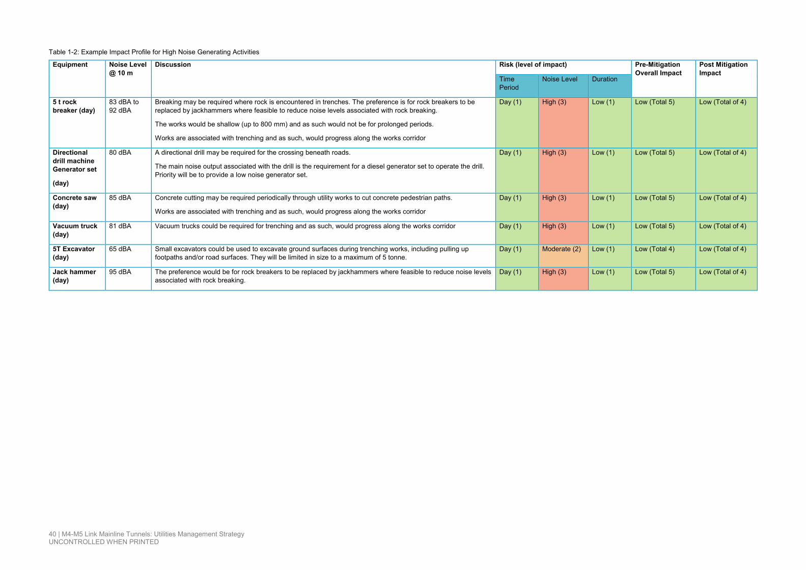
40 | M4-M5 Link Mainline Tunnels: Utilities Management Strategy UNCONTROLLED WHEN PRINTED
Table 1-2: Example Impact Profile for High Noise Generating Activities
Equipment Noise Level @ 10 m
Discussion Risk (level of impact) Pre-Mitigation Overall Impact
Post Mitigation Impact
Time Period
Noise Level Duration
5 t rock breaker (day)
83 dBA to 92 dBA
Breaking may be required where rock is encountered in trenches. The preference is for rock breakers to be replaced by jackhammers where feasible to reduce noise levels associated with rock breaking.
The works would be shallow (up to 800 mm) and as such would not be for prolonged periods.
Works are associated with trenching and as such, would progress along the works corridor
Day (1) High (3) Low (1) Low (Total 5) Low (Total of 4)
Directional drill machine Generator set
(day)
80 dBA A directional drill may be required for the crossing beneath roads.
The main noise output associated with the drill is the requirement for a diesel generator set to operate the drill. Priority will be to provide a low noise generator set.
Day (1) High (3) Low (1) Low (Total 5) Low (Total of 4)
Concrete saw (day)
85 dBA Concrete cutting may be required periodically through utility works to cut concrete pedestrian paths.
Works are associated with trenching and as such, would progress along the works corridor
Day (1) High (3) Low (1) Low (Total 5) Low (Total of 4)
Vacuum truck (day)
81 dBA Vacuum trucks could be required for trenching and as such, would progress along the works corridor Day (1) High (3) Low (1) Low (Total 5) Low (Total of 4)
5T Excavator (day)
65 dBA Small excavators could be used to excavate ground surfaces during trenching works, including pulling up footpaths and/or road surfaces. They will be limited in size to a maximum of 5 tonne.
Day (1) Moderate (2) Low (1) Low (Total 4) Low (Total of 4)
Jack hammer (day)
95 dBA The preference would be for rock breakers to be replaced by jackhammers where feasible to reduce noise levels associated with rock breaking.
Day (1) High (3) Low (1) Low (Total 5) Low (Total of 4)

41 | M4-M5 Link Mainline Tunnels: Utilities Management Strategy UNCONTROLLED WHEN PRINTED
1.2 Traffic and Access Impacts The potential impact associated with changes to established traffic routes (including pedestrian and cyclist) or flows is considered predominantly associated with the duration of the change and the inconvenience of any associated diversions put in place for traffic around the construction works.
Table 1-3: Traffic and Access Impact Matrix
Parameter Score
Duration of change
1. Low – Works directly impact traffic movement for less than 2 consecutive weeks
2. Moderate – Works directly impact traffic movement for between 2 and 4 consecutive weeks
3. High – Works directly impact traffic movement for greater than 4 weeks.
Traffic Impact
1. Low – Delay of less than 10 minutes around work area
2. Moderate – Delay of between 10 and 20 minutes around work area
3. High – Delay of greater than 20 minutes around work area
Pedestrian and cyclist impact
1. Low – Diversion distance less than 100 m
2. Moderate – Diversion distance between 100 m and 500 m
3. High – Diversion distance greater than 500 m
If there are additional accessibility obstacles on the diversion pathway for pedestrians and cyclists (e.g. a stairwell) created for the works, the impact is considered high unless appropriate mitigation measures are put in place.
For the purposes of the assessment of traffic impacts, the degree of traffic or pedestrian/cyclist impact is calculated by summing the duration and impact (either traffic or pedestrian) scores, and then comparing it to the overall traffic impact category below.
Low traffic impact: 2 to 3
Moderate traffic impact: 4 to 5
High traffic impact: Above 5
1.3 Residential Parking On-street parking impacts are deemed to be low where the loss of parking at the location of the works is for one consecutive week or less and alternate on-street parking is available within 100 m of the parking area impacted by the works. However, if special community needs for parking have been determined through consultation with affected stakeholders utilising existing on-and off-street parking stock, the impact is considered high unless appropriate mitigation measures are put in place.

42 | M4-M5 Link Mainline Tunnels: Utilities Management Strategy UNCONTROLLED WHEN PRINTED
1.4 Biodiversity Biodiversity impacts are deemed to be low where no threatened species or threatened ecological communities (within the meaning of the Biodiversity Conservation Act 2016) are adversely affected or potentially adversely affected by the proposed utilities works, unless otherwise determined by the Secretary in consultation with Office of Environment and Heritage (OEH) or Department of Primary Industries (DPI) Fisheries (in the case of impact upon fish, aquatic invertebrates or marine vegetation).
The removal of vegetation (excluding threatened ecological communities) and weed species is deemed as low impact where the vegetation removal has been identified in the EIS, SPIR or a Consistency Assessment.
It is noted that the definition of construction in the CoA excludes “(e) clearing of vegetation, as identified in the EIS and Submissions and Preferred Infrastructure Report”. However, where threatened species or threatened ecological communities are adversely affected or potentially adversely affected by any low impact work that work is deemed construction unless determined by the Secretary in consultation with OEH or DPI Fisheries.
1.5 Heritage Heritage impacts are deemed to be low if known or potential heritage sites or artefacts are not adversely affected or potentially adversely affected by the proposed utilities work, unless otherwise determined by the Secretary in consultation with OEH.
It is noted that the definition of construction excludes “(j) archaeological testing under the Code of practice for archaeological investigation of Aboriginal objects in NSW (DECCW, 2010) or archaeological monitoring undertaken in association with [a]-[i] [in the construction definition list] to ensure that there is no impact on heritage items”.
However, where heritage items are adversely affected or potentially adversely affected by any low impact works, that work is deemed construction unless determined by the Secretary in consultation with OEH.
1.6 Dust Dust impacts are deemed to be low if dust is maintained within the vicinity of the early works area and not creating a nuisance or adversely impacting on sensitive receiver.
1.7 Surface Water Management Surface water impacts are deemed to be low if runoff and tracking from the early works area is controlled to prevent pollution of waterways.
1.8 Lighting Impacts Lighting impacts for works outside of standard working hours are deemed to be low if sensitive receivers are not adversely impacted by nuisance lighting (i.e. lighting is not directed into sensitive receivers properties).

43 | M4-M5 Link Mainline Tunnels: Utilities Management Strategy UNCONTROLLED WHEN PRINTED
2 Low Impact Works Mitigation Measures
Typical management measures that would be implemented during low impact utility works are outlined below.
Environmental Aspect
Management Measure
Traffic and Access
• Construction workers utilise designated off-street car parking areas where available
• Minimise periods of time during which roads and footpaths would be closed
• Install signage to advise road users of any closures and alternative arrangements Where possible undertake works outside peak traffic periods
• Notify affected communities about temporary traffic and access disruptions
• Consultation with the local Council prior to commencement of proposed works
• Where utility works are required within main arterial roads
• For any utility works on main arterial roads, a Road Occupancy Licence (ROL) and coordination with the Traffic Management Centre (TMC) would be required.
Noise and Vibration
• Carry out works during standard construction hours except in specific circumstances where out—of-hours work may be required, such as to avoid traffic impacts on arterial roads during peak periods.
• Scheduling noise intensive works outside of sensitive periods where possible
• Establish an Out-of-Hours Work Protocol to guide how out-of-hours work would be conducted, including community notification procedures for affected neighbours, provisions for respite periods and a complaints handling process
• Use of temporary noise barriers or mobile acoustic enclosures where practicable
• Maintain minimum separation distances between vibration intensive works and sensitive building structures
• Carry out vibration monitoring and complete pre and post-construction condition assessments for sensitive building structures or sensitive equipment likely to be impacted by vibration intensive works.

44 | M4-M5 Link Mainline Tunnels: Utilities Management Strategy UNCONTROLLED WHEN PRINTED
Environmental Aspect
Management Measure
Air quality • Use of water sprays to minimise dust from exposed areas such as trenches and stockpiles
• Avoid and remove deposits of loose materials (eg soils) on impervious surfaces to reduce potential for dust generation
• Covering truck loads, use of wheel washes and street sweepers to minimise tracking of dust
• Regular maintenance of plant and equipment to minimise exhaust emissions
• Turn off vehicles and equipment when not in use.
Biodiversity • Carry out pre-clearing surveys of any potential habitat trees and vegetation to be removed
• Establish tree protection zones around trees to be retained
• Where appropriate, utilise sensitive construction techniques such as under boring to minimise impacts on the roots of high retention values trees
• Minimise removal of vegetation and where appropriate plant replacement trees and vegetation with suitable local native species at completion of construction works
• Manage works to avoid the spread of noxious weeds in accordance with the Noxious Weeds Act 1993 (NSW).
Non-Aboriginal heritage
• Avoid route options that would involve disturbance of listed heritage items • Undertake archival recording of any listed heritage items disturbed
by the works • Minimise the use of vibration-intensive equipment and manage
associated activities in the vicinity of listed heritage items to avoid potential cosmetic damage
• Establish an unexpected heritage finds protocol.
Aboriginal heritage
• Establish an unexpected heritage finds protocol • Check registers to confirm no registered sites • Modify route if necessary • Check for Aboriginal Land claims.
Visual • Sensitive siting and design of above ground utility services to minimise visual impacts
• Careful orientation and shielding of lighting to minimise light spill and glare.
Land use • Undertake prior notification of works to residential, business and other property owners who may be affected.

45 | M4-M5 Link Mainline Tunnels: Utilities Management Strategy UNCONTROLLED WHEN PRINTED
Environmental Aspect
Management Measure
Soil and water • Manage surface water and soils to minimise potential erosion and sedimentation of drains and watercourses in accordance with the requirements of the Blue Book
• Minimise areas of exposed soil surfaces to reduce erosion • Install sediment control measures • Stabilisation of exposed soil surfaces progressively during construction • Nominating exclusion zones during construction works to
protect environmentally sensitive areas such as watercourses • Storing oils and fuels in a suitably bunded, covered and secure area • Adoption of appropriate storage and refuelling controls including a
nominated refuelling area.
Contamination • Adopting standard health and safety management practices • Stabilisation of exposed soil surfaces progressively during construction • Requirements for dewatering of groundwater
• Adopting an unexpected contaminated land finds protocol
Waste • Characterise and manage waste in accordance with the NSW EPA's Waste Classification Guidelines.
Electric
magnetic fields
• Optimise feeder and feeder/joint bay configurations (if required) • Where possible locating feeders to increase separation distances to
sensitive receivers.
Cumulative impacts
• Regular communication with other utility service providers, contractors and proponents of other projects
• Scheduling of work with other overlapping projects to minimise potential cumulative impacts
• Progressively stage construction works to minimise impacts such as traffic, noise and visual impacts.

46 | M4-M5 Link Mainline Tunnels: Utilities Management Strategy UNCONTROLLED WHEN PRINTED
Appendix B
Areas of Interest

!!T
Alt Street
John Street
Queen Street
Croy
don
Road
Church Street
Anthony Street
Bland Street
Knocklayde Stre
et
Eton
ville
Par
ade
Rob
inso
n St
reet
Gillies AvenueBroughton Street
Chandos Street
Kenilworth Street
Bay Street
Henry Street
Cantor Stre
et
Parramatta Road
Martin Street
Earle Avenue
Denman
Avenue
Comet Street
Taringa Street
Wrig
ht S
tree
t
Lang
Str
eet
Lucy
Stre
et
Ranger Road
Charlotte StreetBanks Street
Claude Lane
Vine
Stre
et
Birr
iga
Roa
d
IlfordAvenue
Roge
rsAv
enue
Hunt Street
Astw
in S
treet
TawaStreet
Ivan
hoe
Roa
d
Wolseley Street
Allum Street
Mar
gare
t Stre
et
West Street
Alexandra StreetJone
s St
reet
Byr
on S
tree
t Dalmar Street
Julia Street
Scot
t Str
eet
Curt Street
Bur
ns S
tree
t
Tinana
Street
Dobroyd Parade
Henley Marine Drive
Yasmar Avenue
Page Avenue
Northcote Stre
et
Walker Avenue
Edwin
Stre
et
Albe
rtPa
rade
Ramsay Street
Frederick Street
AlgiePark
AshfieldCentenary
Sports Area
Hammond Park
Dobroyd Canal(Ir
onCo
veCre
ek)
AE
CO
M G
IS P
rinte
d D
ate:
13/
08/2
017
\\A
US
YD
5FP
001\
Driv
e-P
\604
9167
7\4.
Tec
h &
Env
iro w
ork
area
\4.9
9 G
IS\1
0_E
IS\0
2_M
aps\
MX
D_D
DP
_TE
CH
\M4M
5_E
IS_T
R_U
M_0
03_6
0491
677_
A4L
_Util
ities
_man
agem
ent_
stra
tegy
.mxd
Utilities Management StrategyArea of interestSubstationIndicative power supply connection
BoundariesProject footprintAncillary facility
0 140 280 m
!«N#
Wattle Street
LEGEND Imagery © Nearmap (2017)
Power being provided from existing substation
C1a - Wattle Streetcivil and tunnel site
C3a - Northcote Streetcivil site
Cove Street
C1b - Parramatta Road West civil and tunnel site
C3b - Parramatta Road East civil site
C2a - Haberfield civil and tunnel site
C2b - Haberfield civil sit
Alt Street
Figure 4-1 Construction power - Haberfield and Ashfield (Options A and B) 32
!!T
Alt Street
John Street
Queen Street
Croy
don
Road
Church Street
Anthony Street
Bland Street
Knocklayde Stre
et
Eton
ville
Par
ade
Rob
inso
n St
reet
Gillies AvenueBroughton Street
Chandos Street
Kenilworth Street
Bay Street
Henry Street
Cantor Stre
et
Parramatta Road
Martin Street
Earle Avenue
Denman
Avenue
Comet Street
Taringa Street
Wrig
ht S
tree
t
Lang
Str
eet
Lucy
Stre
et
Ranger Road
Charlotte Street
Banks Street
Claude Lane
Vine
Stre
et
Birr
iga
Roa
d
IlfordAvenue
Roge
rsAv
enue
Hunt Street
Astw
in S
treet
TawaStreet
Ivan
hoe
Roa
d
Wolseley Street
Allum Street
Mar
gare
t Stre
et
West Street
Alexandra StreetJone
s St
reet
Byr
on S
tree
t Dalmar Street
Julia Street
Scot
t Str
eet
Curt Street
Bur
ns S
tree
t
Tinana
Street
Dobroyd Parade
Henley Marine Drive
Yasmar Avenue
Page Avenue
Northcote Stre
et
Walker Avenue
Edwin
Stre
et
Albe
rtPa
rade
Ramsay Street
Frederick Street
AlgiePark
AshfieldCentenary
Sports Area
Hammond Park
Dobroyd Canal(Ir
onCo
veCre
ek)
AE
CO
M G
IS P
rinte
d D
ate:
13/
08/2
017
\\A
US
YD
5FP
001\
Driv
e-P
\604
9167
7\4.
Tec
h &
Env
iro w
ork
area
\4.9
9 G
IS\1
0_E
IS\0
2_M
aps\
MX
D_D
DP
_TE
CH
\M4M
5_E
IS_T
R_U
M_0
03_6
0491
677_
A4L
_Util
ities
_man
agem
ent_
stra
tegy
.mxd
Utilities Management StrategyArea of interestSubstationIndicative power supply connection
BoundariesProject footprintAncillary facility
0 140 280 m
!«N#
Wattle Street
LEGEND Imagery © Nearmap (2017)
Power being provided from existing substation
C1a - Wattle Streetcivil and tunnel site
C3a - Northcote Streetcivil site
Cove Street
C1b - Parramatta Road West civil and tunnel site
C3b - Parramatta Road East civil site
C2a - Haberfield civil and tunnel site
C2b - Haberfield civil sit
Alt Street
Figure 4-1 Construction power - Haberfield and Ashfield (Options A and B) 32

LaytonStreet
Mallett Street
Church Street
Lyons Road
Gehrig Lane
Gordon Street
Chester Street
Guihen Street
Parramatta Road
Victory LaneB
ooth StreetHampshire Street
Mason Street
Pyrmont Brid
ge Road
Isabella Street
Broderick Street
Purkis Street
Lambert Street
Bignell Lane
AE
CO
M G
IS P
rinte
d D
ate:
13/
08/2
017
\\A
US
YD
5FP
001\
Driv
e-P
\604
9167
7\4.
Tec
h &
Env
iro w
ork
area
\4.9
9 G
IS\1
0_E
IS\0
2_M
aps\
MX
D_D
DP
_TE
CH
\M4M
5_E
IS_T
R_U
M_0
03_6
0491
677_
A4L
_Util
ities
_man
agem
ent_
stra
tegy
.mxd
Utilities Management StrategyArea of interestSubstationIndicative power supply connection
BoundariesProject footprintAncillary facility
0 30 60 m
!«N#
Power being provided from existing substation
C9 - Pyrmont Bridge Roadtunnel site
LEGEND Imagery © Nearmap (2017)
Figure 4-4 Construction power - Pyrmont Bridge Road, Annandale 35
LaytonStreet
Mallett Street
Church Street
Lyons Road
Gehrig Lane
Gordon Street
Chester Street
Guihen Street
Parramatta Road
Victory Lane
Booth Street
Hampshire Street
Mason Street
Pyrmont Brid
ge Road
Isabella Street
Broderick Street
Purkis Street
Lambert Street
Bignell Lane
AE
CO
M G
IS P
rinte
d D
ate:
13/
08/2
017
\\A
US
YD
5FP
001\
Driv
e-P
\604
9167
7\4.
Tec
h &
Env
iro w
ork
area
\4.9
9 G
IS\1
0_E
IS\0
2_M
aps\
MX
D_D
DP
_TE
CH
\M4M
5_E
IS_T
R_U
M_0
03_6
0491
677_
A4L
_Util
ities
_man
agem
ent_
stra
tegy
.mxd
Utilities Management StrategyArea of interestSubstationIndicative power supply connection
BoundariesProject footprintAncillary facility
0 30 60 m
!«N#
Power being provided from existing substation
C9 - Pyrmont Bridge Roadtunnel site
LEGEND Imagery © Nearmap (2017)
Figure 4-4 Construction power - Pyrmont Bridge Road, Annandale 35

Bar
won
Par
k R
oad
Industry Drive
Orchard Road
News Direct RoadBurrows Road
Canal Road
Campbell Road
Harb
erSt
r eetPrin
ces H
ighway
Gardeners Road
Michael Dann Avenue
Grap
hix
Row
Eust
on R
oad
Sydney Park
Alexandra Canal
AE
CO
M G
IS P
rinte
d D
ate:
13/
08/2
017
\\A
US
YD
5FP
001\
Driv
e-P
\604
9167
7\4.
Tec
h &
Env
iro w
ork
area
\4.9
9 G
IS\1
0_E
IS\0
2_M
aps\
MX
D_D
DP
_TE
CH
\M4M
5_E
IS_T
R_U
M_0
03_6
0491
677_
A4L
_Util
ities
_man
agem
ent_
stra
tegy
.mxd
Existing featuresRailway
Utilities Management StrategyArea of interestSubstationIndicative power supply connection
BoundariesProject footprintAncillary facility
0 100 200 m
!«N#
C10 - Campbell Road civil and tunnel site
Connection to new AusGrid substation
LEGEND Imagery © Nearmap (2017)
Figure 4-7 Permanent power - St Peters 41

!!T
Mackay Street
Alt Street
John Street
Queen Street
Croy
don
Road
Church Street
Anthony Street
Bland Street
Knocklayde Stre
et
Eton
ville
Par
ade
Rob
inso
n St
reet
Gillies AvenueBroughton Street
Chandos Street
Kenilworth Street
Bay Street
Henry Street
Cantor Stre
et
Parramatta Road
Martin Street
Earle Avenue
Denman
Avenue
Comet Street
Taringa Street
Wrig
ht S
tree
t
Lang
Str
eet
Lucy
Stre
et
Ranger Road
Charlotte StreetBanks Street
Claude Lane
Vine
Stre
et
Birr
iga
Roa
d
IlfordAvenue
Roge
rsAv
enue
Hunt Street
Astw
in S
treet
TawaStreet
Ivan
hoe
Roa
d
Wolseley Street
Hedger Avenue
Allum Street
Mar
gare
t Stre
et
West Street
Alexandra StreetJone
s St
reet
Byr
on S
tree
t Dalmar Street
Julia Street
Scot
t Str
eet
Curt Street
Bur
ns S
tree
t
Tinana
Street
Dobroyd Parade
Henley Marine Drive
Yasmar Avenue
Page Avenue
Northcote Stre
et
Walker Avenue
Edwin
Stre
et
Albe
rtPa
rade
Ramsay Street
Frederick Street
AlgiePark
AshfieldCentenary
Sports Area
Hammond Park
AE
CO
M G
IS P
rinte
d D
ate:
13/
08/2
017
\\A
US
YD
5FP
001\
Driv
e-P
\604
9167
7\4.
Tec
h &
Env
iro w
ork
area
\4.9
9 G
IS\1
0_E
IS\0
2_M
aps\
MX
D_D
DP
_TE
CH
\M4M
5_E
IS_T
R_U
M_0
05_6
0491
677_
A4L
_Util
ities
_Zon
ing.
mxd
Utilities Management StrategyArea of interestSubstation
BoundariesProject footprintAncillary facility
Standard Instrument LEPB1 Neighbourhood CentreB2 Local CentreB4 Mixed UseB6 Enterprise Corridor
IN2 Light IndustrialR2 Low Density ResidentialR3 Medium Density Residential
RE1 Public RecreationRE2 Private RecreationSP2 Infrastructure
0 140 280 m
!«N#
LEGEND Imagery © Nearmap (2017)
Power being provided from existing substation
C1a - Wattle Streetcivil and tunnel site
C3a - Northcote Streetcivil site
C1b - Parramatta Road West civil and tunnel site
C3b - Parramatta Road East civil site
Alt Street
C2a - Haberfield civil and tunnel site
C2b - Haberfield civil sit
Wattle Street
Cove Street
Figure 7-2 Construction power - Haberfield and Ashfield (Options A and B) environmental constraints 2 of 2 53
!!T
Mackay Street
Alt Street
John Street
Queen Street
Croy
don
Road
Church Street
Anthony Street
Bland Street
Knocklayde Stre
et
Eton
ville
Par
ade
Rob
inso
n St
reet
Gillies AvenueBroughton Street
Chandos Street
Kenilworth Street
Bay Street
Henry Street
Cantor Stre
et
Parramatta Road
Martin Street
Earle Avenue
Denman
Avenue
Comet Street
Taringa Street
Wrig
ht S
tree
t
Lang
Str
eet
Lucy
Stre
et
Ranger Road
Charlotte Street
Banks Street
Claude Lane
Vine
Stre
et
Birr
iga
Roa
d
IlfordAvenue
Roge
rsAv
enue
Hunt Street
Astw
in S
treet
TawaStreet
Ivan
hoe
Roa
d
Wolseley Street
Hedger Avenue
Allum Street
Mar
gare
t Stre
et
West Street
Alexandra StreetJone
s St
reet
Byr
on S
tree
t Dalmar Street
Julia Street
Scot
t Str
eet
Curt Street
Bur
ns S
tree
t
Tinana
Street
Dobroyd Parade
Henley Marine Drive
Yasmar Avenue
Page Avenue
Northcote Stre
et
Walker Avenue
Edwin
Stre
et
Albe
rtPa
rade
Ramsay Street
Frederick Street
AlgiePark
AshfieldCentenary
Sports Area
Hammond Park
AE
CO
M G
IS P
rinte
d D
ate:
13/
08/2
017
\\A
US
YD
5FP
001\
Driv
e-P
\604
9167
7\4.
Tec
h &
Env
iro w
ork
area
\4.9
9 G
IS\1
0_E
IS\0
2_M
aps\
MX
D_D
DP
_TE
CH
\M4M
5_E
IS_T
R_U
M_0
05_6
0491
677_
A4L
_Util
ities
_Zon
ing.
mxd
Utilities Management StrategyArea of interestSubstation
BoundariesProject footprintAncillary facility
Standard Instrument LEPB1 Neighbourhood CentreB2 Local CentreB4 Mixed UseB6 Enterprise Corridor
IN2 Light IndustrialR2 Low Density ResidentialR3 Medium Density Residential
RE1 Public RecreationRE2 Private RecreationSP2 Infrastructure
0 140 280 m
!«N#
LEGEND Imagery © Nearmap (2017)
Power being provided from existing substation
C1a - Wattle Streetcivil and tunnel site
C3a - Northcote Streetcivil site
C1b - Parramatta Road West civil and tunnel site
C3b - Parramatta Road East civil site
Alt Street
C2a - Haberfield civil and tunnel site
C2b - Haberfield civil sit
Wattle Street
Cove Street
Figure 7-2 Construction power - Haberfield and Ashfield (Options A and B) environmental constraints 2 of 2 53

LaytonStreet
Mallett Street
Lyons Road
Gehrig Lane
Gordon Street
Chester Street
Guihen Street
Victory Lane
Mason Street
Isabella Street
Pyrmont Brid
ge Road
Broderick Street
Purkis Street
Lambert Street
Bignell Lane
AE
CO
M G
IS P
rinte
d D
ate:
13/
08/2
017
\\A
US
YD
5FP
001\
Driv
e-P
\604
9167
7\4.
Tec
h &
Env
iro w
ork
area
\4.9
9 G
IS\1
0_E
IS\0
2_M
aps\
MX
D_D
DP
_TE
CH
\M4M
5_E
IS_T
R_U
M_0
05_6
0491
677_
A4L
_Util
ities
_Env
ironm
enta
l_co
nstr
aint
s.m
xd
Acid sulfate soilsSoil Class 3
Local Environmental Plan Heritage conservation areaHeritage item
Sensitive receivers") Community Centre
0 30 60 m
!«N#
Utilities Management StrategyArea of interestSubstationIndicative power supply connection
BoundariesProject footprintAncillary facility
C9 - Pyrmont Bridge Roadtunnel site
Power being provided from existing substation
Parramatta Road
Imagery © Nearmap (2017)
Figure 7-17 Construction power - Pyrmont Bridge Road environmental constraints 1 of 2 87
LEGEND
KEY

LaytonStreet
Mallett Street
Church Street
Lyons Road
Gehrig Lane
Gordon Street
Chester Street
Guihen Street
Parramatta Road
Victory LaneB
ooth StreetHampshire Street
Mason Street
Pyrmont Brid
ge Road
Isabella Street
Broderick Street
Purkis Street
Lambert Street
Bignell Lane
AE
CO
M G
IS P
rinte
d D
ate:
13/
08/2
017
\\A
US
YD
5FP
001\
Driv
e-P
\604
9167
7\4.
Tec
h &
Env
iro w
ork
area
\4.9
9 G
IS\1
0_E
IS\0
2_M
aps\
MX
D_D
DP
_TE
CH
\M4M
5_E
IS_T
R_U
M_0
05_6
0491
677_
A4L
_Util
ities
_Zon
ing.
mxd
Utilities Management StrategyArea of interestSubstationIndicative power supplyconnection
BoundariesProject footprintAncillary facility
Standard Instrument LEPB1 Neighbourhood CentreB2 Local CentreB4 Mixed Use
IN2 Light IndustrialR1 General ResidentialR2 Low Density Residential
SP2 Infrastructure
0 30 60 m
!«N#
C9 - Pyrmont Bridge Roadtunnel site
Power being provided from existing substation
Imagery © Nearmap (2017)
Figure 7-18 Construction power - Pyrmont Bridge Road environmental constraints 2 of 2 88
LEGEND
LaytonStreet
Mallett Street
Church Street
Lyons Road
Gehrig Lane
Gordon Street
Chester Street
Guihen Street
Parramatta Road
Victory Lane
Booth Street
Hampshire Street
Mason Street
Pyrmont Brid
ge Road
Isabella Street
Broderick Street
Purkis Street
Lambert Street
Bignell Lane
AE
CO
M G
IS P
rinte
d D
ate:
13/
08/2
017
\\A
US
YD
5FP
001\
Driv
e-P
\604
9167
7\4.
Tec
h &
Env
iro w
ork
area
\4.9
9 G
IS\1
0_E
IS\0
2_M
aps\
MX
D_D
DP
_TE
CH
\M4M
5_E
IS_T
R_U
M_0
05_6
0491
677_
A4L
_Util
ities
_Zon
ing.
mxd
Utilities Management StrategyArea of interestSubstationIndicative power supplyconnection
BoundariesProject footprintAncillary facility
Standard Instrument LEPB1 Neighbourhood CentreB2 Local CentreB4 Mixed Use
IN2 Light IndustrialR1 General ResidentialR2 Low Density Residential
SP2 Infrastructure
0 30 60 m
!«N#
C9 - Pyrmont Bridge Roadtunnel site
Power being provided from existing substation
Imagery © Nearmap (2017)
Figure 7-18 Construction power - Pyrmont Bridge Road environmental constraints 2 of 2 88
LEGEND
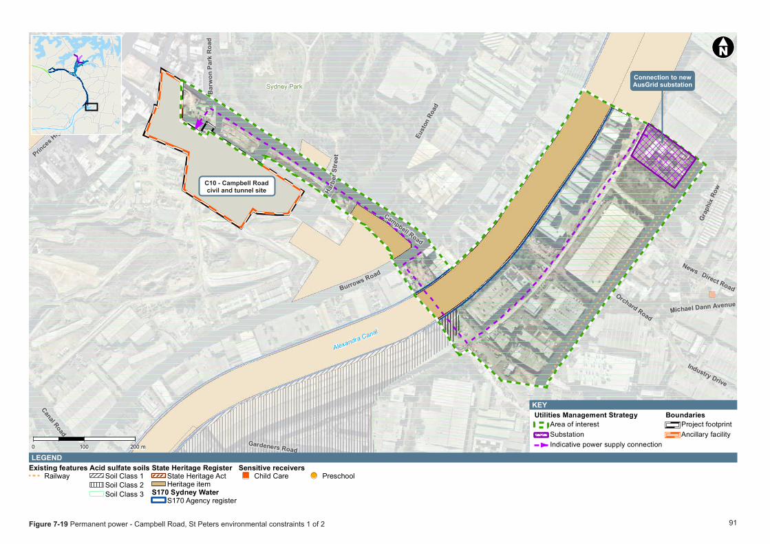
Bar
won
Par
k R
oad
Industry Drive
Orchard Road
News Direct RoadBurrows Road
Canal Road
Campbell Road
Harb
erSt
r eetPrin
ces H
ighway
Gardeners Road
Michael Dann Avenue
Grap
hix
Row
Eust
on R
oad
Sydney Park
Alexandra Canal
AE
CO
M G
IS P
rinte
d D
ate:
13/
08/2
017
\\A
US
YD
5FP
001\
Driv
e-P
\604
9167
7\4.
Tec
h &
Env
iro w
ork
area
\4.9
9 G
IS\1
0_E
IS\0
2_M
aps\
MX
D_D
DP
_TE
CH
\M4M
5_E
IS_T
R_U
M_0
05_6
0491
677_
A4L
_Util
ities
_Env
ironm
enta
l_co
nstr
aint
s.m
xd
Existing featuresRailway
Acid sulfate soilsSoil Class 1Soil Class 2Soil Class 3
State Heritage RegisterState Heritage ActHeritage item
S170 Sydney WaterS170 Agency register
Sensitive receivers") Child Care !( Preschool
0 100 200 m
!«N#
Utilities Management StrategyArea of interestSubstationIndicative power supply connection
BoundariesProject footprintAncillary facility
Connection to new AusGrid substation
Imagery © Nearmap (2017)
C10 - Campbell Road civil and tunnel site
Figure 7-19 Permanent power - Campbell Road, St Peters environmental constraints 1 of 2 91
LEGENDLEGEND
KEY

Bar
won
Par
k R
oad
Industry Drive
Orchard Road
News Direct RoadBurrows Road
Canal Road
Campbell Road
Harb
erSt
r eetPrin
ces H
ighway
Gardeners Road
Michael Dann Avenue
Grap
hix
Row
Eust
on R
oad
Sydney Park
AE
CO
M G
IS P
rinte
d D
ate:
13/
08/2
017
\\A
US
YD
5FP
001\
Driv
e-P
\604
9167
7\4.
Tec
h &
Env
iro w
ork
area
\4.9
9 G
IS\1
0_E
IS\0
2_M
aps\
MX
D_D
DP
_TE
CH
\M4M
5_E
IS_T
R_U
M_0
05_6
0491
677_
A4L
_Util
ities
_Zon
ing.
mxd
Existing featuresRailway
Utilities Management StrategyArea of interestSubstationIndicative power supplyconnection
BoundariesProject footprintAncillary facility
Standard Instrument LEPB4 Mixed UseB6 Enterprise CorridorB7 Business Park
IN1 General IndustrialIN2 Light IndustrialR1 General ResidentialR2 Low Density Residential
RE1 Public RecreationSP1 Special ActivitiesSP2 Infrastructure
0 100 200 m
!«N#
C10 - Campbell Road civil and tunnel site
Connection to new AusGrid substation
Imagery © Nearmap (2017)
Figure 7-20 Permanent power - Campbell Road, St Peters environmental constraints 2 of 2 92
LEGENDLEGEND

Bland Street
Alt
Stre
etParramatta Road
AE
CO
M G
IS P
rinte
d D
ate:
14/
08/2
017
\\A
US
YD
5FP
001\
Driv
e-P
\604
9167
7\4.
Tec
h &
Env
iro w
ork
area
\4.9
9 G
IS\1
0_E
IS\0
2_M
aps\
MX
D_D
DP
_TE
CH
\M4M
5_E
IS_T
R_U
M_0
06_6
0491
677_
A4L
_Exi
stin
g_U
tiliti
es.m
xd
BoundariesProject footprintAncillary facility
Sydney WaterWater main
Sydney WaterSewer main
CommunicationsFibre
0 10 20 m
!«N#
C1b - Parramatta Road Westcivil and tunnel site
C3b - Parramatta Road Eastcivil site
C3b - Parramatta Road East civil site
C1b - Parramatta Road West
civil and tunnel site
Figure A-2 Exisiting utilities - Haberfield/Ashfield (Option
LEGEND
Bland Street
Alt
Stre
et
Parramatta Road
AE
CO
M G
IS P
rinte
d D
ate:
14/
08/2
017
\\A
US
YD
5FP
001\
Driv
e-P
\604
9167
7\4.
Tec
h &
Env
iro w
ork
area
\4.9
9 G
IS\1
0_E
IS\0
2_M
aps\
MX
D_D
DP
_TE
CH
\M4M
5_E
IS_T
R_U
M_0
06_6
0491
677_
A4L
_Exi
stin
g_U
tiliti
es.m
xd
BoundariesProject footprintAncillary facility
Sydney WaterWater main
Sydney WaterSewer main
CommunicationsFibre
0 10 20 m
!«N#
C1b - Parramatta Road Westcivil and tunnel site
C3b - Parramatta Road Eastcivil site
C3b - Parramatta Road East civil site
C1b - Parramatta Road West
civil and tunnel site
Figure A-2 Exisiting utilities - Haberfield/Ashfield (Option
LEGEND

47 | M4-M5 Link Mainline Tunnels: Utilities Management Strategy UNCONTROLLED WHEN PRINTED
Appendix C
Summary of Proposed Utility Works

48 | M4-M5 Link Mainline Tunnels: Utilities Management Strategy UNCONTROLLED WHEN PRINTED
Table C-1 Existing Utility Services, Wattle Street interchange
Utility service Asset Type / Sub-Type Existing location Within ‘Areas of Interest’ Proposed Management Measure
Ausgrid Electrical / Transmission
Running north south direction along Martin Street
Yes Retain and protect as required
Ausgrid Electrical / Distribution LV
Running north south direction along Martin Street
Yes Retain and protect as required
Ausgrid Electrical / Distribution HV Distribution LV
Running north south direction along Ramsay Street
Yes Retain and protect as required
Ausgrid Electrical / Sub Transmission
Running north south direction from Ash Lane onto Wattle Street
Yes Retain and protect as required
Ausgrid Electrical / Distribution HV
Running north south direction along Martin Street
Yes Retain and protect as required
Sydney Water
Water / Reticulation (150mm)
Running north south direction along Parramatta Road crossing Wattle Street
Yes Retain and protect as required
Sydney Water
Water / Reticulation (multiple 100mm assets)
Running east west direction along Wattle Street
Yes Retain and protect as required
Sydney Water
Water / Reticulation (100mm)
Running north south direction along Martin Street
Yes Retain and protect as required
Sydney Water
Water / Trunk (900mm disconnected main)
Running east west direction along Alt Street
Yes Retain and protect as required
Sydney Water
Water / Reticulation (multiple 100mm assets)
Running east west direction along Alt Street
Yes Retain and protect as required

49 | M4-M5 Link Mainline Tunnels: Utilities Management Strategy UNCONTROLLED WHEN PRINTED
Utility service Asset Type / Sub-Type Existing location Within ‘Areas of Interest’ Proposed Management Measure
Sydney Water
Water / Trunk (900mm)
Running north south direction along Ramsay Street
Yes Retain and protect as required
Sydney Water
Water / Reticulation (multiple 150mm assets)
Running north south direction along Ramsay Street
Yes Retain and protect as required
Sydney Water
Sewer / Trunk (300mm)
Running north south direction crossing Wattle Street
Yes Relocation as required
Sydney Water
Sewer / Distribution (multiple 225mm assets)
Running north south direction crossing Wattle Street
Yes Retain and protect (refurbish) as required
Sydney Water
Sewer / Distribution (225mm)
Running east west direction along Wattle Street
Yes Retain and protect as required
Sydney Water
Sewer / Trunk (300mm)
Running north south direction along Martin Street
Yes Relocation as required
Sydney Water
Sewer / Distribution (multiple 225mm assets)
Running north south direction along Martin Street and running from Martin Street to Dobroyd Parade
Yes Relocation or protect (refurbish) (as required)
Sydney Water
Sewer / Distribution (multiple 225mm assets)
Running east west direction along Alt Street
Yes Retain and protect as required
Jemena Gas / Network (7kPa)
Running north south direction along Parramatta Road crossing Wattle Street
Yes Retain and protect as required
Jemena Gas / Network (multiple 7kPa mains)
Running east west direction along Wattle Street
Yes Retain and protect as required

50 | M4-M5 Link Mainline Tunnels: Utilities Management Strategy UNCONTROLLED WHEN PRINTED
Utility service Asset Type / Sub-Type Existing location Within ‘Areas of Interest’ Proposed Management Measure
Jemena Gas / Network (multiple 7kPa mains)
Running north south direction along Ramsay Street
Yes Retain and protect as required
Jemena Gas / Network (7kPa)
Running north south direction along Ramsay Street
Yes Retain and protect as required
Jemena Gas / Network (multiple 7kPa mains)
Running east west direction along Alt Street
Yes Retain and protect as required
Council Stormwater / 1050mm diameter
Running from Iron Cove Creek across Dobroyd Parade
Yes Retain and protect as required

51 | M4-M5 Link Mainline Tunnels: Utilities Management Strategy UNCONTROLLED WHEN PRINTED
Table C-2 Existing Utility Services, PRE&W
Utility service Asset Type / Sub-Type Existing location Within ‘Areas of Interest’ Proposed Management Measure
Telstra Telecommunications / Copper / Fibre (multiple)
Running north south along Parramatta Road
Yes Retain and protect as required
Optus Telecommunications / Major Fibre
Running north south along Parramatta Road
Yes Retain and protect as required
Optus / NBN Telecommunications / Fibre (multiple)
Running north south along Parramatta Road
Yes Retain and protect as required
Optus Telecommunications / Aerial network
Running north south along Parramatta Road
Yes Retain and protect as required
Telstra Telecommunications / Copper / Fibre (multiple)
Running east west along Bland Street
No Retain and protect as required
Optus Telecommunications / Major Fibre
Running east west along Bland Street
No Retain and protect as required
Optus / Uecomm / NBN / PipeNetworks
Telecommunications / Fibre (multiple)
Running east west along Bland Street
No Retain and protect as required
Telstra Telecommunications / Copper (multiple)
Within proposed Muir Site Yes Retain and minor adjustment and/or decommission (if required)
Telstra Telecommunications / Copper (multiple)
Running along Alt Street No Retain and minor adjustment (if required)
NBN Telecommunications / Fibre (multiple)
Running along Alt Street No Retain and protect as required

52 | M4-M5 Link Mainline Tunnels: Utilities Management Strategy UNCONTROLLED WHEN PRINTED
Utility service Asset Type / Sub-Type Existing location Within ‘Areas of Interest’ Proposed Management Measure
Sydney Water Water / Trunk (450mm)
Running along the western side of Parramatta Road
Yes Retain and protect as required
Sydney Water Water / Reticulation (multiple) (250mm / 150mm)
Running north south along Parramatta Road
Yes Retain and protect as required
Sydney Water Water / Reticulation (multiple) (100mm / 150mm)
Running east west along Bland Street
No Retain and protect as required
Sydney Water Water / Reticulation (multiple) (100mm / 150mm)
Running east west along Alt Street No Retain and protect as required
Jemena Gas / Network (multiple 7kPa mains)
Running north south along Parramatta Road
Yes Retain and protect as required
Jemena Gas / Network (multiple 7kPa mains)
Running east west along Bland Street
No Retain and protect as required
Jemena Gas / Network (multiple 7kPa mains)
Running east west along Alt Street No Retain and protect as required
Sydney Water Sewer / Trunk (330mm and 405mm)
Running along the northern side of Bland Street to the west and east of Parramatta Road.
Yes Retain and protect as required
Sydney Water Sewer / Reticulation (150mm) Distribution (225mm)
Running within construction ancillary site on east and west side of Parramatta Road
Yes Retain and protect as required
Sydney Water Sewer / Distribution (225mm)
Running north south along Parramatta Road
Yes Retain and protect as required

53 | M4-M5 Link Mainline Tunnels: Utilities Management Strategy UNCONTROLLED WHEN PRINTED
Utility service Asset Type / Sub-Type Existing location Within ‘Areas of Interest’ Proposed Management Measure
Sydney Water Sewer / Distribution (225mm) (multiple)
Running along Alt Street No Retain and protect as required
Ausgrid transmission
33 kV underground cable
Running along Parramatta Road, Bland Street and Alt Street
Yes Retain and protect as required
Ausgrid Electrical / Distribution HV (multiple)
Running north south along Parramatta Road
No Retain and protect as required
Ausgrid Electrical / Distribution HV (multiple)
Running east west direction along Bland Street and connects with Parramatta Road
No Retain and protect as required
Ausgrid Electrical / Distribution HV (multiple)
Running east west direction along Alt Street and connects with Parramatta Road
No Retain and protect as required
Ausgrid Electrical / Distribution LV and SL
Running north south overhead along Parramatta Road
No Relocation as required
Ausgrid Electrical / Distribution LV (multiple)
Running north south overhead along Parramatta Road
No Retain and protect as required
Ausgrid Electrical / Distribution LV (multiple)
Running east west direction overhead along Bland Street and crossing Bland Street
No Retain and protect as required
Ausgrid Electrical / Distribution LV (multiple)
Running east west direction overhead along Alt Street
No Retain and protect as required
Table C-3 Existing Utility Services, Northcote Street site

54 | M4-M5 Link Mainline Tunnels: Utilities Management Strategy UNCONTROLLED WHEN PRINTED
Utility service Description Existing location Within ‘Areas of Interest’ Proposed management measures
Sydney Water Sewer / Distribution (225mm) (multiple)
Running within construction ancillary site between Wolseley St and Parramatta Road
Yes Retain and protect as required
Sydney Water Water / Reticulation (150mm) (multiple)
Running in road reserve north-south along Parramatta Road
Yes Retain and protect as required
Sydney Water Water / Distribution (200mm)
Running east in road reserve along Wattle Street
Yes Retain and protect as required
Sydney Water Water / Disused
Running east in road reserve / construction site along Northcote Street
Yes Retain and protect as required
Jemena Gas / Network (7kPa mains)
Running north south along Parramatta Road
Yes Retain and protect as required
Jemena Gas / Network (7kPa mains)
Running east along Wolseley Street Yes Retain and protect as required
Jemena Gas / Network (7kPa mains)
Running east along Northcote Street Yes Retain and protect as required
Sydney Trains HV cable Running east-west along Wattle Street into Frederick Street
Yes Retain and protect as required
NBN Telecommunications / Fibre (multiple)
Running along Northcote Street within construction site
Yes Retain and protect as required
Optus Telecommunications / Fibre
Running north-south along Parramatta Road
Yes Retain and protect as required
Telstra Telecommunications / Copper (multiple)
Running along Northcote Street within construction site
Yes Retain and protect as required

55 | M4-M5 Link Mainline Tunnels: Utilities Management Strategy UNCONTROLLED WHEN PRINTED
Utility service Description Existing location Within ‘Areas of Interest’ Proposed management measures
Telstra multi-Fibre optic cables
Telecommunications / Fibre (multiple)
Running north-south along Parramatta Road and Northcote Street
Yes Retain and protect as required
Ausgrid Electrical / Transmission 33kV
Running east west direction along Wolseley Street into Page Avenue
Yes Retain and protect as required
Ausgrid Electrical / Distribution Kiosk
Located in Wolseley Street in public footpath
Yes Retain and protect as required
Ausgrid Electrical / Distribution HV, LV and SL (multiple)
Running east west direction along eastern side of Parramatta Road
Yes Retain and protect as required
Ausgrid Electrical / Distribution HV, LV and SL (multiple)
Running north south direction along southern side of Wolseley Street
Yes Retain and protect as required
Ausgrid Electrical / Distribution HV
Running north south direction in construction site boundary
Yes Retain and protect as required
Ausgrid Electrical / Distribution HV, LV and SL (multiple)
Running east west direction along Wattle Street
Yes Retain and protect as required
Ausgrid Electrical / Distribution HVC Kiosk
2x HVC Kiosks located within construction site boundary
Yes Retain and protect as required
Ausgrid Electrical / Distribution HV
Running east from Croydon ZS, south down Alexandria Street, east down Lucy Street, north along Church Street, east along Knocklayde Street, south down Henry Street, east down Earle Street then south down Parramatta Road.
Yes Install new asset
Table C-4 Existing Utility Services, Pyrmont Bridge Road, Annandale

56 | M4-M5 Link Mainline Tunnels: Utilities Management Strategy UNCONTROLLED WHEN PRINTED
Utility service Description Existing location Within ‘Areas of Interest’ Proposed management measures
Sydney Water Sewer / Trunk (400mm / 300mm)
Running within Bignell Lane Yes Relocation as required
Sydney Water Sewer / Distribution (multiple) (300mm / 225mm)
Running east west along Parramatta Road
No Retain and protect (refurbish) as required
Sydney Water Sewer / Distribution (multiple) (225mm)
Running north south along Mallett Street
No Relocation or retain and protect as required
Sydney Water Sewer / Disused mains Running within Bignell Lane Yes Remove abandoned asset as required
Sydney Water Sewer / Distribution (225m & Vent line)
Running within Bignell Lane Yes Relocation as required
Sydney Water Sewer / Distribution (300mm)
Running northeast southwest along Pyrmont Bridge Road
No Retain and protect as required
Sydney Water Water / Trunk (900mm)
Running northeast southwest along Pyrmont Bridge Road
No Retain and protect as required
Sydney Water Water / Trunk (900mm)
Running east west along Parramatta Road
No Retain and protect as required
Sydney Water Water / Distribution (multiple) (300mm)
Running east west along Parramatta Road
No Relocation as required
Sydney Water Water / Reticulation (multiple) (100mm)
Running along Bignell Lane Yes Relocation or retain and protect as required
Sydney Water Water / Reticulation (100mm)
Running along Mallett Street Yes Relocation as required

57 | M4-M5 Link Mainline Tunnels: Utilities Management Strategy UNCONTROLLED WHEN PRINTED
Utility service Description Existing location Within ‘Areas of Interest’ Proposed management measures
Jemena Gas / Network (multiple 210kPa mains)
Running east west along Parramatta Road
No Relocation or retain and protect as required
Jemena Gas / Network (210kPa)
Running northeast southwest along Pyrmont Bridge Road
No Retain and protect as required
Telstra multi-Fibre optic cables
Underground multi-fibre cables
Running along the northern verge of Parramatta Road adjacent to the southern boundary of the site
Yes Retain and protect as required
Telstra Underground multi-fibre cables
Running northeast along Pyrmont Bridge Road
Yes Retain and protect as required
Optus Telecommunications / Major Fibre
Running east west along Parramatta Road
Yes Retain and protect as required
Ausgrid Electrical / Distribution (multiple)
Running east west along Parramatta Road
Yes Retain and protect as required
Ausgrid Electrical / Transmission & Distribution
Running north south along Mallett Street
Yes Retain and protect as required
Ausgrid Electrical / Distribution Running northeast along Pyrmont Bridge Road
Yes Retain and protect as required
Ausgrid Electrical / Distribution (multiple)
Running along Bignell Lane Yes Remove assets as required
Ausgrid Electrical / Distribution HV
Running west from Camperdown ZS to Layton Street, then north along Layton Street, then west along Mason Street, then south down Mallet Street to the site at Bingell Lane
Yes Install new asset

58 | M4-M5 Link Mainline Tunnels: Utilities Management Strategy UNCONTROLLED WHEN PRINTED
Table C-5 Existing Utility Services, St Peters interchange, including Campbell Road civil and tunnel site
Utility service Asset Type / Sub-Type Existing location Within ‘Areas of Interest’ Proposed Management Measure
Ausgrid Electrical / Transmission
Running north south direction along Barwon Park Road
Yes Retain and protect as required
Ausgrid Electrical / Distribution (multiple)
Running east west direction along Campbell Street
Yes Retain and protect as required
Ausgrid Electrical / Distribution (multiple)
Running east west direction along Campbell Street
Yes Retain and protect as required
Ausgrid Electrical / Distribution (multiple)
Running east west direction along Crown Street
Yes Retain and protect as required
Ausgrid Electrical / Chamber substation
475 Princes Highway Yes Retain and protect as required
Ausgrid Electrical / Distribution (multiple)
Running east west direction along Princes Highway
Yes Retain and protect as required
Ausgrid Electrical / Transmission
Running from Alexandria ZS south-west along private property to proposed road at Campbell Road, west across Alexandra Canal, then continuing west along Campbell Road to the site
Yes Install new asset
Sydney Water Water / Distribution (250mm)
Running east west along Campbell Street
Yes Retain and protect as required
Sydney Water Water / Reticulation (multiple)
Running east west along Campbell Street
Yes Retain and protect as required
Sydney Water Water / Reticulation (180mm)
Running north south along Crown Street
Yes Retain and protect as required

59 | M4-M5 Link Mainline Tunnels: Utilities Management Strategy UNCONTROLLED WHEN PRINTED
Utility service Asset Type / Sub-Type Existing location Within ‘Areas of Interest’ Proposed Management Measure
Sydney Water Water / Reticulation (multiple)
Running north south along Princes Highway
Yes Retain and protect as required
Sydney Water Sewer / Distribution (multiple)
Running east west direction along Campbell Street
Yes Retain and monitor as required
Sydney Water Sewer / Distribution
Running north south direction along Campbell Street
Yes Remove assets as required
Sydney Water Sewer / Distribution
Running east-west direction between properties between Princes Highway and Crown Street
Yes Retain and monitor as required
Sydney Water Sewer / Reticulation
Running east-west direction between properties between Barwon Park Road and Crown Street
Yes Retain and monitor as required
Sydney Water Sewer / Distribution
Running east-west direction between properties between Barwon Park Road and Crown Street
Yes Retain and monitor as required
Sydney Water Sewer / Distribution
north-south direction along Woodley Street from Campbell Street
Yes Remove assets as required
Jemena Gas / Network (7kPa)
Running east-west direction on southern side of Campbell Street / Albert Street
Yes Retain and monitor as required
Jemena Gas / Secondary (1050kPa) (multiple)
Running north than east then south along Campbell Street
Yes Retain and monitor as required
Jemena Gas / Network (multiple)
Running east-west and north-south direction along Campbell Street
Yes Retain and monitor as required
Jemena Gas / Network (multiple)
Running east-west and north-south direction along Crown Street
Yes Retain and monitor as required
Jemena Gas / Secondary (1050kPa)
Running north south on Princes Highway
Yes Retain and monitor as required

60 | M4-M5 Link Mainline Tunnels: Utilities Management Strategy UNCONTROLLED WHEN PRINTED
Utility service Asset Type / Sub-Type Existing location Within ‘Areas of Interest’ Proposed Management Measure
Jemena Gas / Network (multiple)
Running north south on Princes Highway
Yes Retain and monitor as required
Telstra & Optus
Underground cables fibre and copper (multiple)
Running along Campbell Street (both sides)
Yes Retain and protect as required
Telstra & Optus
Underground cables copper (multiple)
Running north along Crown Street (both sides)
Yes Retain and protect as required
Telstra & Optus
Underground cables fibre and copper (multiple)
Running along Princes Highway Street (both sides)
Yes Retain and protect as required
Optus Underground cables fibre and copper (multiple)
Running east-west direction on southern side of Campbell Street
Yes Retain and protect as required
Table C-6 Existing Utility Services, White Bay parking and laydown site, White Bay
Utility service Description Existing location Within ‘Areas of Interest’ Proposed management measures
Ausgrid Electrical / High Voltage
Running through the site northwest south east direction
TBC Retain and monitor as required
Ausgrid Electrical / High Voltage
Running overhead to the west of the site
TBC Retain and monitor as required
Sydney Water Sewer / Distribution (multiple 225m & Vent line)
Running through the site northwest south east direction
Yes Retain and protect as required
Table C-7 Existing Utility Services Sydney Water, Mainline Tunnels
Utility service Description Existing location Within ‘Areas of Interest’ Proposed management measures

61 | M4-M5 Link Mainline Tunnels: Utilities Management Strategy UNCONTROLLED WHEN PRINTED
Sydney Water Water / Pressure Tunnel Trunk (2700mm)
Crossing the Tunnel alignment approx. ch. 2780
Yes Retain and protect as required
Sydney Water Water / City1Tunnel Trunk (2700mm)
Crossing the Tunnel alignment approx. ch. 2250
Yes Retain and protect as required