Embed Size (px)
Citation preview

~ 566 ~
ISSN Print: 2394-7500
ISSN Online: 2394-5869
Impact Factor: 5.2
IJAR 2016; 2(9): 566-578
www.allresearchjournal.com
Received: 20-07-2016
Accepted: 21-08-2016
M Vindhya
M. Tech Student Visvodaya
Engineering College, Kavali,
SPSR Nellore, Andhra
Pradesh, India
Dr. T Suresh Babu
HOD and Professor
Department of Civil
Engineering, Visvodaya
Engineering College, Kavali,
SPSR Nellore, Andhra
Pradesh, India
Correspondence
M Vindhya
M. Tech Student Visvodaya
Engineering College, Kavali,
SPSR Nellore, Andhra
Pradesh, India
Utilisation of silica fume & steel slag in concrete as a
partial replacement of cement & coarse aggregate
M Vindhya and Dr. T Suresh Babu
Abstract
In This paper an evaluation of steel slag aggregate in concrete with and without adding silica fume in
comparison with the conventional natural aggregate concrete. Hardened concrete consist of more than
70% aggregate due to the high demand in building construction and the increase of demand of the
amount of material, suppliers and researchers are exploring the use of alternative materials which could
decrease the usage of natural sources and save the environment. Steel slag was used as an aggregate
replacement in conventional concrete mixes. Steel slag which is mainly consists of calcium carbonate is
produced as a by-product during the oxidation process in steel industry. Steel slag was selected due to
its characteristics, which are almost similar to conventional aggregates and the fact that it is easily
obtainable as a by-product of the steel industry. As a result, utilization of steel slag will save natural
resources and clean environment. Steel slag Particle packing analysis is made to match the grade of
coarse aggregate which would decrease the cement requirement and increase the density of packing
which would result in its improved performance in terms of strength and other parameters. Silica
fume is a by-product of producing silicon metal or ferrosilicon alloys. One of the most beneficial uses
for silica fume is usage in concrete. Because of its chemical and physical properties, it is a very reactive
pozzolanic. Concrete containing silica fume can have very high strength and can be very durable. Silica
fume is non-metallic and non-hazardous waste of industries. It is suitable for concrete mix and
improves properties of concrete i.e. compressive strength etc. by experimental study of usage of steel
slag and silica fume with replacement of coarse aggregate and silica fume made clear that it increases
strength nearly twice the mix grade. the study of mechanical properties and silica \fume gives the
details of the behavior of the concrete during various tests
Keywords: SCM, steel slag concrete, steel slag, silica fume
1. Introduction
1.1 General Concrete is a mixture of cement, sand, coarse aggregate and water. Its success lies in its
versatility as can be designed to withstand harshest environments while taking on the most
inspirational forms. Engineers and scientists are further trying to increase its limits with the
help of innovative chemical admixtures and various supplementary cementitious materials
SCM’s. Early SCM’s consisted of natural, readily available materials like volcanic ash or
diatomaceous earth. The engineering marvels like Roman aqueducts, the Coliseum are
examples of this technique used by the Greeks and Romans. Nowadays, the most concrete
mixture contains SCM’s which are mainly by-products or waste materials from other
industrial processes.
1.2 Scope And Objective
The scope and objective of this present project investigation is to increase the strength of
concrete by using silica fume & steel slag.
To increase the strength of concrete by partial replacement of coarse aggregate with steel
slag which is a waste material produced from steel industries.
The main objective of this project is to get high strength by using normal mix
proportions with partial replacement of silica fume in cement and steel slag in coarse
aggregate.
International Journal of Applied Research 2016; 2(9): 566-578

~ 567 ~
International Journal of Applied Research
2. Experimental Program
2.1 Materials Used The different materials used in this investigation are:
1. Cement
2. Fine aggregates
3. Coarse aggregates
4. Mineral admixtures - silica fume
5. Steel slag
6. Water
2.1.1 Cement
Cement is a binding material, which is the combination of
two raw materials called calcareous and argillaceous
materials. Zuari-53 grade ordinary Portland cement
conforming to IS: 12269 were used.
Table 2.1: Shows the results of physical tests on ordinary Portland
cement of 53 grades
Serial No Physical tests Obtained results
1 Fineness 6.8%
2 Standard consistency 31%
3 Initial setting time 40 min
4 Final setting time 290 min
5 Specific gravity 3.15
6 Compressive strength Kg/cm2
2.1.2 Fine Aggregate
The standard sand used in this investigation was obtained
from Pennar River, Nellore. The standard sand shall be of
quartz, light gray or whitish variety and shall be free from
silt. The sand grains shall be angular, the shape of the grains
approximating to the spherical form elongated and flattened
grains being present only in very small or negligible
quantities. The standard sand shall (100 percent) pass
through 2-mm IS sieve and shall be (100 percent) retained
on 90-micron IS Sieve and the sieves shall conform to IS
460 (Part: 1): 1985.
Table 2.2: Shows the results of physical tests on fine aggregate
S. no Test Obtained results
1 Bulking of sand 3.57%
2 Specific gravity of sand 2.65
3 Sieve analysis of sand ZONE- III as per IS:383-1980
2.1.3 Coarse Aggregates
According to IS 383: 1970, coarse aggregate may be
described as crushed gravel or stone when it results from
crushing of gravel or hard stone. The coarse aggregate
procured from the quarry was sieved through the sieved of
sizes 20 mm and 10 mm respectively. The aggregate passing
through 20 mm IS sieve and retained on 10 mm IS sieve was
taken. The Specific gravity of the coarse aggregate is 2.64.
Table 2.3: Shows the results of physical tests on coarse aggregates
Serial no Tests Obtained results
1 Impact test 18.31%
2 Crushing test 24.58%
3 Specific gravity 2.71
4 Water absorption 1%
5 Flakiness index 17.02%
6 Elongation index 21.40%
2.1.4 Silica Fume
Silica fume is a by-product of producing silicon metal or
Ferrosilicon alloys. One of the most beneficial uses for silica
fume is in concrete. Because of its chemical and physical
properties, it is a very reactive Pozzolanic. Concrete
containing silica fume can have very high strength and can
be very durable. Silica fume is available from suppliers of
concrete admixtures and, when specified, is simply added
during concrete production. Placing, finishing, and curing
silica-fume concrete requires special attention on the part of
the concrete contractor.
The physical properties and chemical composition of silica
fume values are listed as per the manufacturer’s manual in
the below tables:
Table 2.4: shows the physical properties of silica fume
Physical Properties Results
Physical State Micronized Powder
Odour Odourless
Appearance White Colour Powder
Colour White
Pack Density 0.76 gm/cc
PH Of 5% Solution 6.90
Specific Gravity 2.63
Moisture 0.058%
Oil Absorption 55 ml / 100 gms
2.1.5 Steel Slag
Table 2.5: Shows the results of physical tests on coarse aggregates
(steel slag)
Serial no Tests Obtained results
1 Impact test 17.65%
2 Crushing test 23.86%
3 Specific gravity 3.42
4 Water absorption 1.5%
5 Flakiness index 15.81%
6 Elongation index 19.92%
2.1.6 Water
Portable water was used in the experimental work for both
preparing and curing. The pH value of water taken is not
less than 6.
3. Mix Design
3.1 Mix Proportion
Designed to mix proportions for M20 grade concrete is
mentioned below table.
Table 3.1: shows the designed mix proportion values for the M20
grade concrete mix.
Cement Fine aggregates Coarse aggregates Water
387 568 1207 191.6
1 1.467 3.118 0.49
3.2 Calculation of Materials Quantity
We required 8.1 kg of materials for making one M20 grade
concrete cube of size 150 mm X 150 mm X 150 mm. As per
the mix design, materials required for making of one M20-
grade concrete cube of size 150 mm X 150 mm X 150 mm
cube are shown below table for various mix proportions.

~ 568 ~
International Journal of Applied Research
Table 3.2: shows the materials required for making of one M20
grade concrete cube with various mix proportions of silica fume
S.
No
Mix
proportion
in %
Cement
in
grams
Silica
fume
in
grams
Fine
aggregate
in grams
Coarse
aggregate
in grams
1 0 1450 0 2127 4522
2 10 1305 145 2127 4522
3 20 1160 290 2127 4522
4 30 1015 435 2127 4522
5 40 870 580 2127 4522
6 50 725 725 2127 4522
Table 3.3: shows the materials required for making of one M20-
grade concrete cube with various mix proportions of steel slag
S.
No
Mix
proportion
in %
Cement
in
grams
Fine
aggregate
in grams
Coarse
aggregate
in grams
Steel
slag in
grams
1 0 1450 2127 4522 0
2 10 1450 2127 4070 452
3 20 1450 2127 3617 905
4 30 1450 2127 3165 1357
5 40 1450 2127 2713 1809
6 50 1450 2127 2261 2261
Table 3.4: shows the materials required for making of one M20grade concrete cube with mix proportions using both silica fume and steel
slag
S.
no
Mix proportion in
%
Cement in
grams
Silica fume in
grams
Fine aggregate in
grams
Coarse aggregate in
grams
Steel slag in
grams
1 20 1160 290 2127 3617 905
4. Tests on Concrete Tests conducted on fresh concrete in the lab as well as site
for quality controls are
1. Slump test
2. Compaction factor test
4.1 Slump Test
The fresh concrete would vertically settle when the lateral
supports are removed. This settlement is called a slump and
various values of the slump are preferred for various
constructions. The Slump is the measure indicating the
consistency or workability of cement concrete and gives the
w/c ratio needed for mixing concrete for different works.
Fig 4.1: Slump test apparatus
Table 4.1.1: shows the slump values of various mix proportions
using silica fume.
Mix proportion in % Slump in cm
0 1
10 0
20 1
30 2
40 0
50 1
Table 4.1.2: shows the slump values of various mix proportions
using steel slag.
Mix proportion in % Slump in cm
0 1
10 1
20 0
30 1
40 0
50 2
4.2 Compaction Factor Test (Reference: IS: 1199 – 1959)
This test is adopted to find out the workability of concrete,
where nominal size of the aggregate does not exceed 40
mm. This test is based upon the definition that workability is
the amount of work done to bring the concrete to full
compaction.
The workability of the concrete mix has been observed by
conducting the compaction factor test.
Fig 4.1: Compaction factor test apparatus
Table 4.2.1: shows the compaction factor values for various mix
proportions using silica fume
Mix Proportion In % Compaction Factor Test
0% 0.87
10% 0.85
20% 0.84
30% 0.82
40% 0.81
50% 0.80
Table 4.2.2: shows the compaction factor values for various mix
proportions using silica fume.
Mix proportion in % Compaction factor test
0% 0.87
10% 0.89
20% 0.88
30% 0.85
40% 0.83
50% 0.81
4.3 Compressive Strength Test Representative samples of concrete shall be taken and used
for casting cubes 15 cm x 15 cm x 15 cm. The Compressive
strength is calculated by using the following formula:
Compressive strength (kg/cm2) = Wf / Ap

~ 569 ~
International Journal of Applied Research
Where
Wf = Maximum applied load just before the load, (kg)
Ap = Plan area of cube mould, (mm2)
Fig 4.2: Concrete Cube testing
4.3 Splitting Tensile Of Concrete
The concrete is very weak in tension due to its brittle nature
and is not expected to resist the direct tension. The concrete
develops cracks when subjected to tensile forces. Thus, it is
necessary to determine the tensile strength of concrete
to determine the load at which the concrete members may
crack.
The splitting tensile strength is calculated using the formula
Tsp = 2P/ πDL
Where, P = applied load, D = diameter of the specimen, L =
length of the specimen
Fig 4.3: split tensile testing
4.4 Stress- Strain Test
A Sample of cylinder is placed in compressometer with its
ends fixed tightly and then it is placed in the Compression
testing machine and load is applied constantly and initially a
dial gauge is fixed to the compressometer. With the help of
this deflection readings are taken at constant load. For every
10kN load, deflection values are taken until the specimen
breaks. Diameter of cylinder = 150mm Height of the
cylinder = 300mm Area = 150 x 150 mm2: Gauge Length =
148mm.
Fig 4.4(a): fixed rings and steel rod for stress-strain test
Fig 4.4(b): loading position for stress-strain test
4.5 Stress-Strain Curve Relationship
Concrete belongs to a class of materials that can be called
‘Strain – softening’, indicating a reduction in stress beyond
the peak value with an increase in the deformation (as
against the strain hardening behaviour commonly exhibited
by metals like steel). Figure5.4.5 (b) shows different types
of material behavior.
Fig 4.5(a): Different types of material behavior
Although the ductility of concrete is several orders of
magnitude lower than steel, it still exhibits considerable
deformation before failure In conventional testing machines,
where the test is performed under control of loading rate, a
sudden failure of the specimen occurs as soon as the
maximum load level is reached – the machine gives small
increments of load to the specimen and the resultant
deformation is measured, as a result, when the incremental
load goes over the maximum level, the specimen fractures
suddenly. This is depicted in Figure 4.5(b). In order to
obtain the entire stress-strain graph, inclusive of the post
peak region, deformation or strain controlled test must be
performed.
Fig 4.5(b): Modes of testing – Green indicates load control, red
indicates displacement control
~ 570 ~
International Journal of Applied Research
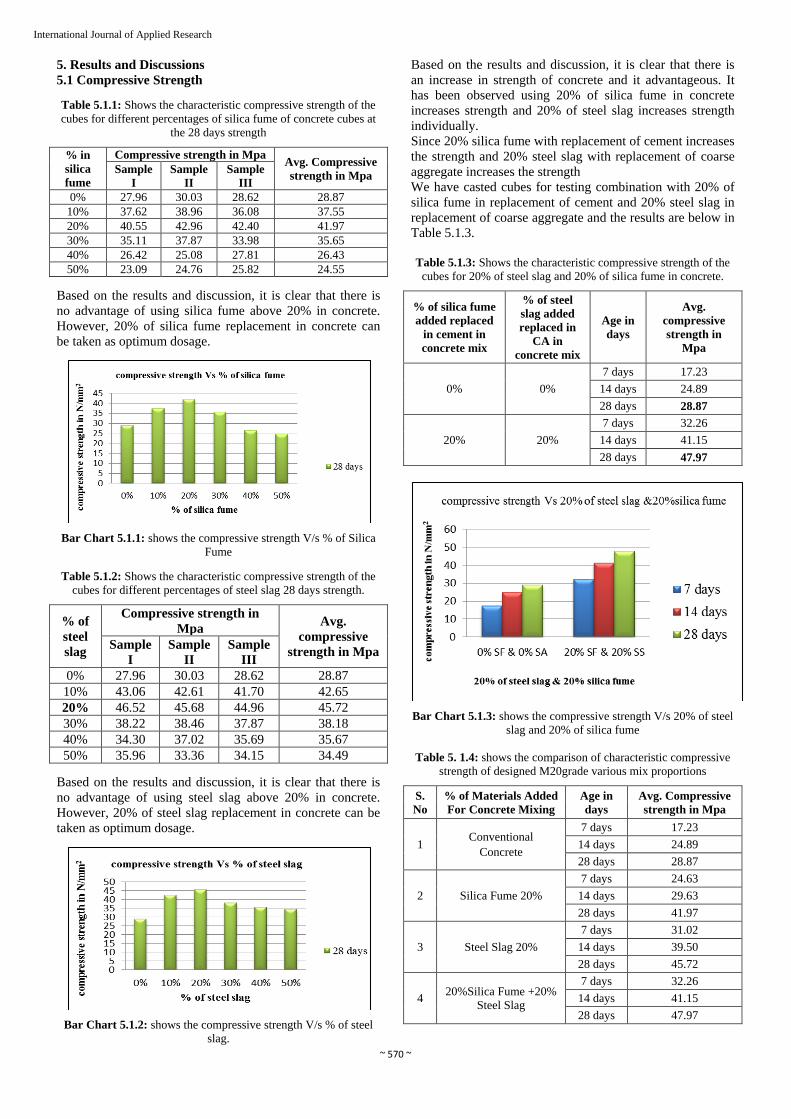
5. Results and Discussions
5.1 Compressive Strength
Table 5.1.1: Shows the characteristic compressive strength of the
cubes for different percentages of silica fume of concrete cubes at
the 28 days strength
% in
silica
fume
Compressive strength in Mpa Avg. Compressive
strength in Mpa Sample
I
Sample
II
Sample
III
0% 27.96 30.03 28.62 28.87
10% 37.62 38.96 36.08 37.55
20% 40.55 42.96 42.40 41.97
30% 35.11 37.87 33.98 35.65
40% 26.42 25.08 27.81 26.43
50% 23.09 24.76 25.82 24.55
Based on the results and discussion, it is clear that there is
no advantage of using silica fume above 20% in concrete.
However, 20% of silica fume replacement in concrete can
be taken as optimum dosage.
Bar Chart 5.1.1: shows the compressive strength V/s % of Silica
Fume
Table 5.1.2: Shows the characteristic compressive strength of the
cubes for different percentages of steel slag 28 days strength.
% of
steel
slag
Compressive strength in
Mpa Avg.
compressive
strength in Mpa Sample
I
Sample
II
Sample
III
0% 27.96 30.03 28.62 28.87
10% 43.06 42.61 41.70 42.65
20% 46.52 45.68 44.96 45.72
30% 38.22 38.46 37.87 38.18
40% 34.30 37.02 35.69 35.67
50% 35.96 33.36 34.15 34.49
Based on the results and discussion, it is clear that there is
no advantage of using steel slag above 20% in concrete.
However, 20% of steel slag replacement in concrete can be
taken as optimum dosage.
Bar Chart 5.1.2: shows the compressive strength V/s % of steel
slag.
Based on the results and discussion, it is clear that there is
an increase in strength of concrete and it advantageous. It
has been observed using 20% of silica fume in concrete
increases strength and 20% of steel slag increases strength
individually.
Since 20% silica fume with replacement of cement increases
the strength and 20% steel slag with replacement of coarse
aggregate increases the strength
We have casted cubes for testing combination with 20% of
silica fume in replacement of cement and 20% steel slag in
replacement of coarse aggregate and the results are below in
Table 5.1.3.
Table 5.1.3: Shows the characteristic compressive strength of the
cubes for 20% of steel slag and 20% of silica fume in concrete.
% of silica fume
added replaced
in cement in
concrete mix
% of steel
slag added
replaced in
CA in
concrete mix
Age in
days
Avg.
compressive
strength in
Mpa
0% 0%
7 days 17.23
14 days 24.89
28 days 28.87
20% 20%
7 days 32.26
14 days 41.15
28 days 47.97
Bar Chart 5.1.3: shows the compressive strength V/s 20% of steel
slag and 20% of silica fume
Table 5. 1.4: shows the comparison of characteristic compressive
strength of designed M20grade various mix proportions
S.
No
% of Materials Added
For Concrete Mixing
Age in
days
Avg. Compressive
strength in Mpa
1 Conventional
Concrete
7 days 17.23
14 days 24.89
28 days 28.87
2 Silica Fume 20%
7 days 24.63
14 days 29.63
28 days 41.97
3 Steel Slag 20%
7 days 31.02
14 days 39.50
28 days 45.72
4 20%Silica Fume +20%
Steel Slag
7 days 32.26
14 days 41.15
28 days 47.97
~ 571 ~
International Journal of Applied Research
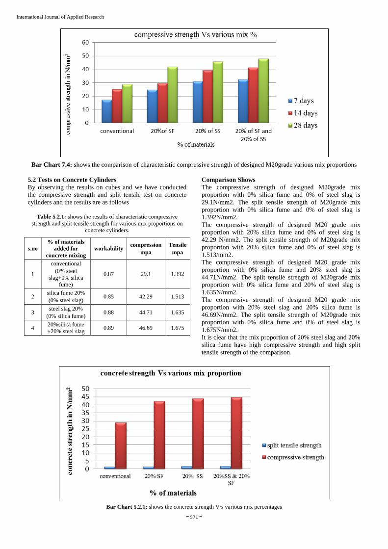
Bar Chart 7.4: shows the comparison of characteristic compressive strength of designed M20grade various mix proportions
5.2 Tests on Concrete Cylinders
By observing the results on cubes and we have conducted
the compressive strength and split tensile test on concrete
cylinders and the results are as follows
Table 5.2.1: shows the results of characteristic compressive
strength and split tensile strength for various mix proportions on
concrete cylinders.
s.no
% of materials
added for
concrete mixing
workability compression
mpa
Tensile
mpa
1
conventional
(0% steel
slag+0% silica
fume)
0.87 29.1 1.392
2 silica fume 20%
(0% steel slag) 0.85 42.29 1.513
3 steel slag 20%
(0% silica fume) 0.88 44.71 1.635
4 20%silica fume
+20% steel slag 0.89 46.69 1.675
Comparison Shows
The compressive strength of designed M20grade mix
proportion with 0% silica fume and 0% of steel slag is
29.1N/mm2. The split tensile strength of M20grade mix
proportion with 0% silica fume and 0% of steel slag is
1.392N/mm2.
The compressive strength of designed M20 grade mix
proportion with 20% silica fume and 0% of steel slag is
42.29 N/mm2. The split tensile strength of M20grade mix
proportion with 20% silica fume and 0% of steel slag is
1.513/mm2.
The compressive strength of designed M20 grade mix
proportion with 0% silica fume and 20% steel slag is
44.71N/mm2. The split tensile strength of M20grade mix
proportion with 0% silica fume and 20% of steel slag is
1.635N/mm2.
The compressive strength of designed M20 grade mix
proportion with 20% steel slag and 20% silica fume is
46.69N/mm2. The split tensile strength of M20grade mix
proportion with 0% silica fume and 0% of steel slag is
1.675N/mm2.
It is clear that the mix proportion of 20% steel slag and 20%
silica fume have high compressive strength and high split
tensile strength of the comparison.
Bar Chart 5.2.1: shows the concrete strength V/s various mix percentages

~ 572 ~
International Journal of Applied Research
2. Stress-Strain Results
The relationship between stress and strain is important in
understanding the basic elastic behaviour of concrete in
hardened state which is useful in design of concrete
Structures. From the values of stresses and strains, average
stress-strain curve for each mix is plotted, taking the average
values of the results.
The following tables are the results and stress strain values
for concrete cylinders which are casted with different %
percentages of various materials and their relationship with
their behavior is shown in the graphs drawn below the
tables.
Conventional concrete (specimen-1): stress-strain values
Load(Kn) Deflection Strain Stress (Kn/ mm2)
0 0.000 0.00000 0.0000
20 0.010 0.00007 1.1318
40 0.015 0.00010 2.2635
60 0.020 0.00014 3.3953
80 0.030 0.00020 4.5271
100 0.038 0.00026 5.6588
120 0.040 0.00027 6.7906
140 0.048 0.00032 7.9224
160 0.057 0.00039 9.0541
180 0.060 0.00041 10.1859
200 0.074 0.00050 11.3177
220 0.085 0.00057 12.4495
240 0.090 0.00061 13.5812
260 0.095 0.00064 14.7130
280 0.099 0.00067 15.8448
300 0.100 0.00068 16.9765
320 0.130 0.00088 18.1083
340 0.135 0.00091 19.2401
360 0.140 0.00095 20.3718
380 0.150 0.00101 21.5036
400 0.200 0.00135 22.6354
420 0.240 0.00162 23.7671
440 0.250 0.00169 24.8989
420 0.300 0.00203 23.7671
400 0.330 0.00223 22.6354
380 0.338 0.00228 21.5036
360 0.340 0.00230 20.3718
340 0.350 0.00236 19.2401
320 0.400 0.00270 18.1083
300 0.410 0.00277 16.9765
280 0.420 0.00284 15.8448
Conventional concrete (specimen-2): stress-strain values
Load(Kn) Deflection Strain Stress (Kn/ mm2)
0 0.000 0.00000 0.0000
20 0.015 0.00010 1.1318
40 0.020 0.00014 2.2635
60 0.030 0.00020 3.3953
80 0.038 0.00026 4.5271
100 0.040 0.00027 5.6588
120 0.048 0.00032 6.7906
140 0.057 0.00039 7.9224
160 0.060 0.00041 9.0541
180 0.074 0.00050 10.1859
200 0.085 0.00057 11.3177
220 0.090 0.00061 12.4495
240 0.095 0.00064 13.5812
260 0.099 0.00067 14.7130
280 0.100 0.00068 15.8448
300 0.130 0.00088 16.9765
320 0.135 0.00091 18.1083
340 0.140 0.00095 19.2401
360 0.150 0.00101 20.3718
380 0.155 0.00105 21.5036
400 0.160 0.00108 22.6354
420 0.165 0.00111 23.7671
440 0.170 0.00115 24.8989
460 0.175 0.00118 26.0307
440 0.182 0.00123 24.8989
420 0.186 0.00126 23.7671
400 0.190 0.00128 22.6354
380 0.200 0.00135 21.5036
360 0.240 0.00162 20.3718
340 0.250 0.00169 19.2401
320 0.300 0.00203 18.1083
300 0.330 0.00223 16.9765
280 0.340 0.00230 15.8448
Curve 1: Conventional concrete (specimen-1): stress-strain curve
~ 573 ~
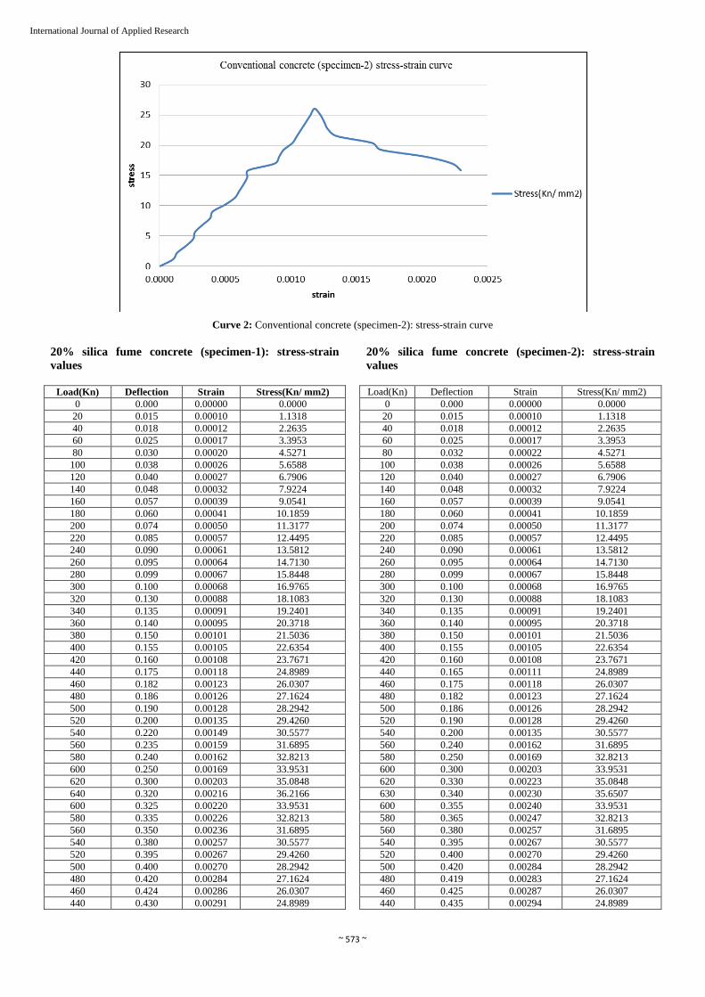
International Journal of Applied Research
Curve 2: Conventional concrete (specimen-2): stress-strain curve
20% silica fume concrete (specimen-1): stress-strain
values
Load(Kn) Deflection Strain Stress(Kn/ mm2)
0 0.000 0.00000 0.0000
20 0.015 0.00010 1.1318
40 0.018 0.00012 2.2635
60 0.025 0.00017 3.3953
80 0.030 0.00020 4.5271
100 0.038 0.00026 5.6588
120 0.040 0.00027 6.7906
140 0.048 0.00032 7.9224
160 0.057 0.00039 9.0541
180 0.060 0.00041 10.1859
200 0.074 0.00050 11.3177
220 0.085 0.00057 12.4495
240 0.090 0.00061 13.5812
260 0.095 0.00064 14.7130
280 0.099 0.00067 15.8448
300 0.100 0.00068 16.9765
320 0.130 0.00088 18.1083
340 0.135 0.00091 19.2401
360 0.140 0.00095 20.3718
380 0.150 0.00101 21.5036
400 0.155 0.00105 22.6354
420 0.160 0.00108 23.7671
440 0.175 0.00118 24.8989
460 0.182 0.00123 26.0307
480 0.186 0.00126 27.1624
500 0.190 0.00128 28.2942
520 0.200 0.00135 29.4260
540 0.220 0.00149 30.5577
560 0.235 0.00159 31.6895
580 0.240 0.00162 32.8213
600 0.250 0.00169 33.9531
620 0.300 0.00203 35.0848
640 0.320 0.00216 36.2166
600 0.325 0.00220 33.9531
580 0.335 0.00226 32.8213
560 0.350 0.00236 31.6895
540 0.380 0.00257 30.5577
520 0.395 0.00267 29.4260
500 0.400 0.00270 28.2942
480 0.420 0.00284 27.1624
460 0.424 0.00286 26.0307
440 0.430 0.00291 24.8989
20% silica fume concrete (specimen-2): stress-strain
values
Load(Kn) Deflection Strain Stress(Kn/ mm2)
0 0.000 0.00000 0.0000
20 0.015 0.00010 1.1318
40 0.018 0.00012 2.2635
60 0.025 0.00017 3.3953
80 0.032 0.00022 4.5271
100 0.038 0.00026 5.6588
120 0.040 0.00027 6.7906
140 0.048 0.00032 7.9224
160 0.057 0.00039 9.0541
180 0.060 0.00041 10.1859
200 0.074 0.00050 11.3177
220 0.085 0.00057 12.4495
240 0.090 0.00061 13.5812
260 0.095 0.00064 14.7130
280 0.099 0.00067 15.8448
300 0.100 0.00068 16.9765
320 0.130 0.00088 18.1083
340 0.135 0.00091 19.2401
360 0.140 0.00095 20.3718
380 0.150 0.00101 21.5036
400 0.155 0.00105 22.6354
420 0.160 0.00108 23.7671
440 0.165 0.00111 24.8989
460 0.175 0.00118 26.0307
480 0.182 0.00123 27.1624
500 0.186 0.00126 28.2942
520 0.190 0.00128 29.4260
540 0.200 0.00135 30.5577
560 0.240 0.00162 31.6895
580 0.250 0.00169 32.8213
600 0.300 0.00203 33.9531
620 0.330 0.00223 35.0848
630 0.340 0.00230 35.6507
600 0.355 0.00240 33.9531
580 0.365 0.00247 32.8213
560 0.380 0.00257 31.6895
540 0.395 0.00267 30.5577
520 0.400 0.00270 29.4260
500 0.420 0.00284 28.2942
480 0.419 0.00283 27.1624
460 0.425 0.00287 26.0307
440 0.435 0.00294 24.8989

~ 574 ~
International Journal of Applied Research
Curve 3: 20% silica fume concrete (specimen-1): stress-strain curve
Curve-4: 20% silica fume concrete (specimen-2): stress-strain curve
20% steel slag concrete (specimen-1): stress-strain values
Load (Kn) Deflection Strain Stress (Kn/ mm2)
0 0.000 0.00000 0.0000
20 0.015 0.00010 1.1318
40 0.018 0.00012 2.2635
60 0.025 0.00017 3.3953
80 0.030 0.00020 4.5271
100 0.038 0.00026 5.6588
120 0.040 0.00027 6.7906
140 0.043 0.00029 7.9224
160 0.045 0.00030 9.0541
180 0.048 0.00032 10.1859
200 0.057 0.00039 11.3177
220 0.060 0.00041 12.4495
240 0.074 0.00050 13.5812
260 0.085 0.00057 14.7130
280 0.090 0.00061 15.8448
300 0.095 0.00064 16.9765
320 0.099 0.00067 18.1083
340 0.100 0.00068 19.2401
360 0.130 0.00088 20.3718
380 0.135 0.00091 21.5036
400 0.140 0.00095 22.6354
420 0.150 0.00101 23.7671
440 0.155 0.00105 24.8989
460 0.160 0.00108 26.0307
480 0.165 0.00111 27.1624
500 0.170 0.00115 28.2942
520 0.175 0.00118 29.4260
540 0.182 0.00123 30.5577
560 0.186 0.00126 31.6895
580 0.190 0.00128 32.8213
600 0.200 0.00135 33.9531
620 0.240 0.00162 35.0848
640 0.250 0.00169 36.2166
660 0.300 0.00203 37.3484
680 0.330 0.00223 38.4801
700 0.340 0.00230 39.6119
720 0.355 0.00240 40.7437
700 0.365 0.00247 39.6119
680 0.380 0.00257 38.4801
660 0.395 0.00267 37.3484
640 0.400 0.00270 36.2166
620 0.420 0.00284 35.0848
600 0.419 0.00283 33.9531
580 0.425 0.00287 32.8213
560 0.435 0.00294 31.6895
540 0.440 0.00297 30.5577
520 0.510 0.00345 29.4260
500 0.530 0.00358 28.2942

~ 575 ~
International Journal of Applied Research
20% steel slag concrete (specimen-2): stress-strain value
Load (Kn) Deflection Strain Stress (Kn/ mm2)
0 0.000 0.00000 0.0000
20 0.010 0.00007 1.1318
40 0.015 0.00010 2.2635
60 0.025 0.00017 3.3953
80 0.030 0.00020 4.5271
100 0.038 0.00026 5.6588
120 0.040 0.00027 6.7906
140 0.045 0.00030 7.9224
160 0.048 0.00032 9.0541
180 0.057 0.00039 10.1859
200 0.060 0.00041 11.3177
220 0.074 0.00050 12.4495
240 0.085 0.00057 13.5812
260 0.090 0.00061 14.7130
280 0.099 0.00067 15.8448
300 0.100 0.00068 16.9765
320 0.120 0.00081 18.1083
340 0.130 0.00088 19.2401
360 0.135 0.00091 20.3718
380 0.140 0.00095 21.5036
400 0.150 0.00101 22.6354
420 0.155 0.00105 23.7671
440 0.182 0.00123 24.8989
460 0.186 0.00126 26.0307
480 0.190 0.00128 27.1624
500 0.200 0.00135 28.2942
520 0.230 0.00155 29.4260
540 0.245 0.00166 30.5577
560 0.250 0.00169 31.6895
580 0.255 0.00172 32.8213
600 0.267 0.00180 33.9531
620 0.280 0.00189 35.0848
640 0.295 0.00199 36.2166
660 0.300 0.00203 37.3484
680 0.325 0.00220 38.4801
700 0.330 0.00223 39.6119
720 0.350 0.00236 40.7437
740 0.385 0.00260 41.8754
720 0.400 0.00270 40.7437
700 0.430 0.00291 39.6119
680 0.450 0.00304 38.4801
660 0.480 0.00324 37.3484
640 0.540 0.00365 36.2166
620 0.545 0.00368 35.0848
600 0.550 0.00372 33.9531
580 0.560 0.00378 32.8213
560 0.580 0.00392 31.6895
Curve 5: 20% steel slag concrete (specimen-1): stress-strain curve
Curve 6: 20% steel slag concrete (specimen-2): stress-strain curve
20% steel slag+20% steel slag concrete (specimen-1):
stress-strain value
Load (Kn) Deflection Strain Stress (Kn/ mm2)
0 0.000 0.00000 0.0000
20 0.012 0.00008 1.1318
40 0.015 0.00010 2.2635
60 0.025 0.00017 3.3953
80 0.030 0.00020 4.5271
100 0.038 0.00026 5.6588
120 0.040 0.00027 6.7906
140 0.045 0.00030 7.9224
160 0.048 0.00032 9.0541
180 0.057 0.00039 10.1859
200 0.060 0.00041 11.3177
220 0.074 0.00050 12.4495
240 0.085 0.00057 13.5812
260 0.090 0.00061 14.7130
280 0.099 0.00067 15.8448
300 0.100 0.00068 16.9765
320 0.120 0.00081 18.1083
340 0.130 0.00088 19.2401
360 0.135 0.00091 20.3718
380 0.140 0.00095 21.5036
400 0.150 0.00101 22.6354
420 0.155 0.00105 23.7671
440 0.182 0.00123 24.8989
460 0.186 0.00126 26.0307
480 0.190 0.00128 27.1624
500 0.200 0.00135 28.2942
520 0.230 0.00155 29.4260
540 0.245 0.00166 30.5577
560 0.250 0.00169 31.6895
580 0.255 0.00172 32.8213
600 0.267 0.00180 33.9531
620 0.280 0.00189 35.0848
640 0.295 0.00199 36.2166
660 0.300 0.00203 37.3484
680 0.325 0.00220 38.4801
700 0.330 0.00223 39.6119
720 0.400 0.00270 40.7437
740 0.450 0.00304 41.8754
760 0.460 0.00311 43.0072
740 0.480 0.00324 41.8754
720 0.540 0.00365 40.7437
700 0.545 0.00368 39.6119
680 0.550 0.00372 38.4801
660 0.560 0.00378 37.3484
640 0.580 0.00392 36.2166
620 0.595 0.00402 35.0848
600 0.630 0.00426 33.9531
580 0.650 0.00439 32.8213

~ 576 ~
International Journal of Applied Research
20% steel slag+20% steel slag concrete (specimen-2):
stress-strain value
Load(Kn) Deflection Strain Stress(Kn/ mm2)
0 0.000 0.00000 0.0000
20 0.009 0.00006 1.1318
40 0.012 0.00008 2.2635
60 0.015 0.00010 3.3953
80 0.025 0.00017 4.5271
100 0.030 0.00020 5.6588
120 0.040 0.00027 6.7906
140 0.045 0.00030 7.9224
160 0.048 0.00032 9.0541
180 0.057 0.00039 10.1859
200 0.060 0.00041 11.3177
220 0.074 0.00050 12.4495
240 0.085 0.00057 13.5812
260 0.090 0.00061 14.7130
280 0.100 0.00068 15.8448
300 0.120 0.00081 16.9765
320 0.130 0.00088 18.1083
340 0.140 0.00095 19.2401
360 0.150 0.00101 20.3718
380 0.155 0.00105 21.5036
400 0.182 0.00123 22.6354
420 0.186 0.00126 23.7671
440 0.190 0.00128 24.8989
460 0.200 0.00135 26.0307
480 0.230 0.00155 27.1624
500 0.245 0.00166 28.2942
520 0.250 0.00169 29.4260
540 0.255 0.00172 30.5577
560 0.267 0.00180 31.6895
580 0.280 0.00189 32.8213
600 0.295 0.00199 33.9531
620 0.300 0.00203 35.0848
640 0.325 0.00220 36.2166
660 0.330 0.00223 37.3484
680 0.400 0.00270 38.4801
700 0.420 0.00284 39.6119
720 0.435 0.00294 40.7437
740 0.445 0.00301 41.8754
760 0.450 0.00304 43.0072
780 0.455 0.00307 44.1390
760 0.460 0.00311 43.0072
740 0.480 0.00324 41.8754
720 0.540 0.00365 40.7437
700 0.545 0.00368 39.6119
680 0.550 0.00372 38.4801
660 0.560 0.00378 37.3484
640 0.580 0.00392 36.2166
620 0.595 0.00402 35.0848
600 0.630 0.00426 33.9531
580 0.650 0.00439 32.8213
560 0.655 0.00443 29.9919
Curve 7: 20% steel slag+20% steel slag concrete (specimen-1):
stress-strain curve
Curve 8: 20% steel slag+20% steel slag concrete (specimen-2):
stress-strain curve
Table 6.3.1: shows the relation between the stress-strain values and area under the stress-strain curve
% of materials added for concrete
mixing
Average
Peak Stress
(Kn/ mm2)
Strain
Corresponding
To Peak Stress
Average Total Strain
Average Area Under Stress-
Strain Curve
(Kn/ mm2)
conventional 25.4648 0.0014 0.0319 0.04315
20%silica fume (0% steel slag) 35.9336 0.0022 0.0527 0.07046
20%steel slag (0% silica fume) 41.3095 0.0025 0.06785 0.010743
20%silica fume + 20%steel slag 43.5731 0.003 0.08579 0.13308
Comparison Shows
The average peak stress for 0% steel slag+0% silica
fume is 25. Kn/mm2; the average total strain is 0.0319.
The average peak stress for 0% steel slag+20% silica
fume is 35.9336 Kn/mm2; the average total strain is
0.0040.
The average peak stress for 20% steel slag+0% silica
fume is 41.3095Kn/mm2; the average total strain is
0.06785.
The average peak stress for 20% steel slag+20% silica
fume is 43.5731Kn/mm2; the average total strain is
0.08579
If we observe all the curve nearly with similar shape
and similar characteristic properties and the shape of
curves are strain-softening as shown in Fig 4.5(a)
Curves of for 20% steel slag+20% silica fume is some
extent showing elastic–plastic curve as shown in Fig
4.5(a)

~ 577 ~
International Journal of Applied Research
It is clear that the mix proportion of 20% steel slag and 20%
silica fume have high peak stress and low strain
development and less area under the stress-strain curve.
6. Conclusions
Based on the experimental work carried out on partial
replacement of cement with steel slag and partial
replacement of coarse aggregate with steel slag for M20
grade concrete the following conclusion are mentioned
below:
1. The partial replacement of cement with silica fume at
optimum dosage has improved the mechanical
properties such as compressive strength by 45.32% &
tensile strength by 8.621%
2. The partial replacement of coarse aggregate with steel
slag at optimum dosage has improved the mechanical
properties such as compressive strength by 53.64% &
tensile strength by 17.45%
3. Beyond the addition of optimum dosage of silica fume
the compression strength has decreased by 8-15% when
silica fume was replaced at 40% and 50%
4. Beyond the addition of optimum dosage of steel slag
the compression strength has increased by very low
percentage of 19-24% when steel slag was replaced at
40% and 50%
5. The stress-strain behaviour of conventional concrete,
concrete with silica fume & concrete with steel slag
have similar pattern
6. The only variation in stress- strain behaviour is the peak
stress values for different percentage of replacement of
cement with silica fume and different percentage of
replacement of coarse aggregate with steel slag
For the combination of 20% steel slag and 20% silica
fume
1. The partial replacement of cement with silica fume and
partial replacement of coarse aggregate with steel slag
at optimum dosage has improved the mechanical
properties such as compressive strength by 62.59% &
tensile strength by 20.33%
2. The stress-strain behaviour of combination concrete i.e.,
20% silica fume & 20% steel slag is similar to
conventional concrete, with silica fume & with steel
slag
3. The only variation in stress-strain behaviour of
combination concrete i.e., 20% silica fume & 20% steel
slag in the peak stress values
By blending the industrial waste in concrete the
following benefits can be obtained
By effective utilization of industrial waste the
mechanical properties are improved
Cost variation is very low because the products silica
fume is very low cost and steel slag is industrial waste
no cost is applied except transportation cost.
Since the amount of cement and coarse aggregate are
reduced the cost of production of concrete is also
reduces.
If the industrial waste is disposed in environment it
will cause environment pollution. By using the
industrial waste in concrete it reduces the
environmental pollution which is in other way eco-
friendly.
The problems of disposing industrial waste are more
now-a-days. More land is required for disposing rather
than that by using industrial waste we can solve some
disposal problems.
7. References
1. Vishal, Ghutke S, Pranita, Bhandari S. Influence of
silica fume on concrete (IOSR Journal of Mechanical
and Civil Engineering (IOSR-JMCE) e -ISSN: 2278-
1684,-ISSN: 2320-334X PP 44-47).
2. Amudhavalli N K, Jeena Mathew. Effect of silica fume
on strength and durability Parameters of concrete by
(International Journal of Engineering Sciences &
Emerging Technologies, August 2012; 3(1):28-35.
ISSN: 2231 – 6604
3. Vikas Srivastava, Alvin Harison, Mehta PK, Atul,
Rakesh Kumar. Effect of Silica Fume in Concrete
(International Journal of Innovative Research in
Science, Engineering and Technology. An ISO 3297:
Certified Organization. 2007; 3(4) March 2014)
4. Saravanan J, Suganya N. Mechanical Properties Of
Concrete Using Steel Slag Aggregate
5. Murthi P, Alan S, Chakkaravarthi C, Raguraman N,
Seenivasan P. Sustainable Replacement Of Steel Slag
As Coarse Aggregate In Concrete
6. Mohammed Nadeem, Arun D Pofale. Utilization Of
Industrial Waste Slag As Aggregate In Concrete
Applications By Adopting Taguchi’s Approach For
Optimization
7. Thangaselvi K. Strength and durability of concrete
using steel slag as a partial replacement of coarse
aggregate in concrete by (International Journal of
Advanced Research Trends in Engineering and
Technology (IJARTET) 2015; 2(7).
8. Dr. Chinnaraju k, Ramkumar VR, Lineesh K, Nithya S,
Sathish V. Study On Concrete Using Steel Slag As
Coarse Aggregate Replacement And Ecosand As Fine
Aggregate Replacement by ((International Journal of
Research in Engineering & Advanced Technology,
2013; 1(3).(IJREAT)ISSN:2320-8791) www.ijreat.org
9. Experimental Investigation on Replacement of Steel
Slag as Coarse Aggregate in Concrete by Ravikumar
H1, Dr. J.K. Dattatreya2, Dr. K.P Shivananda3 (Journal
of Civil Engineering and Environmental Technology.
ISSN : 2349-8404; Online ISSN : 2349-879X 2015;
2(11):58-63.
10. Mohammed thariq. Experimental Investigation Of
Silica Fume And Steel Slag In Concrete by
(international Journal of Advanced Science and
Engineering Research www.ijaser.in 2016; 1(1): ISSN:
2455-9288)
11. Sanjay Kumar Athya, Miss Ragini Mishra. Effect Of
Silica Fume On Different Strength Parameter Of Steel
Slag Concrete (International Journal Of Innovation In
Engineering Research & Management Issn :2348-4918)
12. Kunda Sindhu Priya Reddy, AVS Sai Kumar. Effect Of
Silica Fume On Steel Slag Concrete (International
Journal Of Scientific Engineering And Technology
Research Issn 2319-8885 2015; 04(50)10761-10765
Www.Ijsetr.Com)
13. Devaraj P Kumbar, Gundakalle V D. A Study On Effect
Of Silica Fume On The Mechanical Properties Of Steel
Slag Aggregate Concrete (International journal of
structural and civil engineering research)

~ 578 ~
International Journal of Applied Research
14. Experimental Study On Effect Of Silica Fume On Steel
Slag Concrete by Ajay1, Nikhil Jain2 (International
Journal of All Research Education and Scientific
Methods (IJARESM) ISSN: 2455-6211, 2016; 4(7)
Impact Factor: 2.287)
15. Alaa M Rashad, Hosam El-Din, Seleem H, Amr
Shaheen F. Effect of Silica Fume and Slag on
Compressive Strength and Abrasion Resistance of
HVFA Concrete (International Journal of Concrete
Structures and Materials 2014; 8(1):69-81,
16. Karthik D, Doraikkannan J. Experimental Investigation
of Silica Fume and Steel Slag in Concrete (International
Journal Of Modern Engineering Research (IJMER)
17. Strength Modification Of Steel Slag Concrete Due To
Silica Fume by Sumeet Thakur1 by SSRG
(International Journal of Civil Engineering SSRG-
IJCE)– EFES, 2015
18. Shetty MS, Chand S. Concrete technology & co, 2004.
19. Neville AM. Concrete technology – Pearson publication
20. Astraa Chemicals. Certificate analyses of silica fume
(Micro silica) properties, Chennai.
21. Vishal, Ghutke S, Pranita, Bhandari S. Influence of
silica fume on concrete (IOSR Journal of Mechanical
and Civil Engineering (IOSR-JMCE) e -ISSN: 2278-
1684, p-ISSN: 2320-334X PP 44-47).
22. Amudhavalli NK, Jeena Mathew. Effect of silica fume
on strength and durability Parameters of concrete
(International Journal of Engineering Sciences &
Emerging Technologies, 2012; 3(1):28-35. ISSN: 2231-
6604
23. Vikas Srivastava, Alvin Harison, Mehta PK, Atul,
Rakesh Kumar. Effect of Silica Fume in Concrete
(International Journal of Innovative Research in
Science, Engineering and Technology. An ISO 3297:
2007 Certified Organization, 2014, 3(4).


![2 3 4 5 void ordered_fill (float* array, int array_length) { int index; for (index = 0; index < array_length; index++) { array[index] = index; }](https://img.dokumen.tips/doc/110x75/56649e0d5503460f94af6e07/2-3-4-5-void-orderedfill-float-array-int-arraylength-int-index-for.jpg)


![INDEX [] · 2019-04-15 · INDEX ... index](https://img.dokumen.tips/doc/110x75/5e5bc6adf543e8499e5ad9a4/index-2019-04-15-index-index.jpg)
![index [] · index ... index](https://img.dokumen.tips/doc/110x75/5e33c50d475fc05b6d5265f9/index-index-index.jpg)
![767 INDEX [] · 767 INDEX ... index](https://img.dokumen.tips/doc/110x75/5e6407d785e377181b6fee19/767-index-767-index-index-.jpg)