Embed Size (px)
Citation preview

Pegler Automation, Inc.
Marine and Industrial Controls PMB# 53 305 SE Chkalov Dr. Suite 103 Vancouver, WA 98683
Voice: 503-329-5377 Fax: 425-955-5704 Email:[email protected] PAGE 1 OF 25
file: USNS Observation Island Radar Power survey June 2007 date created: 6/29/2007 10:05:00 PM
Prepared for:
Raytheon Technical Services Co LLC
By:
PMB#53 305 SE Chkalov Drive Suite 103 Vancouver, WA 98683 PH: 503-329-5377 Fax: 425-955-5704

Pegler Automation, Inc.
Marine and Industrial Controls PMB# 53 305 SE Chkalov Dr. Suite 103 Vancouver, WA 98683
Voice: 503-329-5377 Fax: 425-955-5704 Email:[email protected] PAGE 2 OF 25
file: USNS Observation Island Radar Power survey June 2007 date created: 6/29/2007 10:05:00 PM
Vessel: USNS Observation Island Date: 7/20/2007 During a system grooming period after the ROH 2007 shipyard period the X Band Transmitter, Servos and the S Band Radars were monitored for power quality issues at various loads. A previous survey had demonstrated a high level of harmonic distortion in the vessels power supply system. A high level of electrolysis is being witnessed at the vessels evaporators, and it was questioned that due to recent power conversions of the Bow Thruster 1000 HP DC Drive and the X and S band Radars power systems a high level of impressed DC current could be entering the ship’s hull from these systems. Numerous throttling valves have failed due to apparent electrolysis with plating of material witnessed in the evaporator feedheaters. An analysis of the materials found in the feedheater was performed by others, and the results of this testing were not available at the time of this writing. The evaporator piping has had ground bonding straps added in the past few years and was checked for possible galvanic corrosion issues. The throttling valves which had been failing at a high rate were for controlling the flow of the feedwater into the evaporator from the feedheater at 175 degrees F. These valves were made of Bronze, with the feedwater and piping being made of Cupro nickel. The feedwater control valve casings were failing, sometimes within a month of installation. This phenomenon has been occurring with increased regularity within the past 2 or 3 years (The time period when the power conversions were completed on the Bow Thruster and Radar power systems). No significant galvanic coupling was detected at the evaporators, and no significant electrolysis was observed with the Bow Thruster or Radar systems energized and cycled throughout their operating ranges. The most likely cause of the electrolysis is ground faults in the vessels supply system. It has been witnessed on several occasions that ground faults are not immediately cleared on the main ship’s service bus due to mission constraints or other factors, and multiple ground faults can exist thereby allowing current to flow through the ship’s hull. Arcing faults will produce extremely high levels of DC on the bus thereby allowing extreme cases of electrolysis to occur. A grounding system is employed in the X Band and S band turrets, but no detectable current was flowing through this conductor during testing. Upon entering the ROH period both the evaporator brine pumps had low insulation resistance readings and had to be rewound. The following pictures reflect the problem area of the evaporators:

Pegler Automation, Inc.
Marine and Industrial Controls PMB# 53 305 SE Chkalov Dr. Suite 103 Vancouver, WA 98683
Voice: 503-329-5377 Fax: 425-955-5704 Email:[email protected] PAGE 3 OF 25
file: USNS Observation Island Radar Power survey June 2007 date created: 6/29/2007 10:05:00 PM
No. 2 Evaporator Feedwater Piping. New monel control valve was installed ROH 2007
Detail view of control valve showing ground bonding straps and source of galvanic coupling at bracket from evaporator pedestal holding control valve flange.

Pegler Automation, Inc.
Marine and Industrial Controls PMB# 53 305 SE Chkalov Dr. Suite 103 Vancouver, WA 98683
Voice: 503-329-5377 Fax: 425-955-5704 Email:[email protected] PAGE 4 OF 25
file: USNS Observation Island Radar Power survey June 2007 date created: 6/29/2007 10:05:00 PM
Type of throttling globe valve which had been failing
Detail of valve body showing high levels of corrosion

Pegler Automation, Inc.
Marine and Industrial Controls PMB# 53 305 SE Chkalov Dr. Suite 103 Vancouver, WA 98683
Voice: 503-329-5377 Fax: 425-955-5704 Email:[email protected] PAGE 5 OF 25
file: USNS Observation Island Radar Power survey June 2007 date created: 6/29/2007 10:05:00 PM
Valve inlet showing small degree of material failure at inlet weir
Valve outlet had failed and was rebuilt with unknown composition epoxy type material

Pegler Automation, Inc.
Marine and Industrial Controls PMB# 53 305 SE Chkalov Dr. Suite 103 Vancouver, WA 98683
Voice: 503-329-5377 Fax: 425-955-5704 Email:[email protected] PAGE 6 OF 25
file: USNS Observation Island Radar Power survey June 2007 date created: 6/29/2007 10:05:00 PM
Evaporator Feedheater with end bell removed
Detail of electroplating of feedheater tube bundle

Pegler Automation, Inc.
Marine and Industrial Controls PMB# 53 305 SE Chkalov Dr. Suite 103 Vancouver, WA 98683
Voice: 503-329-5377 Fax: 425-955-5704 Email:[email protected] PAGE 7 OF 25
file: USNS Observation Island Radar Power survey June 2007 date created: 6/29/2007 10:05:00 PM
Additional Views of Electroplating

Pegler Automation, Inc.
Marine and Industrial Controls PMB# 53 305 SE Chkalov Dr. Suite 103 Vancouver, WA 98683
Voice: 503-329-5377 Fax: 425-955-5704 Email:[email protected] PAGE 8 OF 25
file: USNS Observation Island Radar Power survey June 2007 date created: 6/29/2007 10:05:00 PM
View of Diffuser

Pegler Automation, Inc.
Marine and Industrial Controls PMB# 53 305 SE Chkalov Dr. Suite 103 Vancouver, WA 98683
Voice: 503-329-5377 Fax: 425-955-5704 Email:[email protected] PAGE 9 OF 25
file: USNS Observation Island Radar Power survey June 2007 date created: 6/29/2007 10:05:00 PM
Besides the failure of the evaporator control valves numerous circuit card failures (Wager Smoke detectors) and PLC failures (Bridge) have been experienced. Other motor bearing failures, tripping, and overheating of salt water circ pumps have been observed. The ship’s supply system was evaluated for detrimental harmonic distortion. The following data sets were recorded: X Band Transmitter (Measured at Main switchboard circuit breaker P-61) Current Waveforms At Idle Load with brief excursions to 2%:
Typical low power waveform. A high degree of current imbalance was observed.

Pegler Automation, Inc.
Marine and Industrial Controls PMB# 53 305 SE Chkalov Dr. Suite 103 Vancouver, WA 98683
Voice: 503-329-5377 Fax: 425-955-5704 Email:[email protected] PAGE 10 OF 25
file: USNS Observation Island Radar Power survey June 2007 date created: 6/29/2007 10:05:00 PM
Voltage waveforms at 2% power. Reflected waveform is 2.1% harmonic distortion. This distortion is well under the recommended 5% upper limit (Per IEEE 519-1992). The following current waveform was recorded at 2% X Band duty cycle.
The following waveforms were recorded at 10% duty cycle of the X band Radar.

Pegler Automation, Inc.
Marine and Industrial Controls PMB# 53 305 SE Chkalov Dr. Suite 103 Vancouver, WA 98683
Voice: 503-329-5377 Fax: 425-955-5704 Email:[email protected] PAGE 11 OF 25
file: USNS Observation Island Radar Power survey June 2007 date created: 6/29/2007 10:05:00 PM

Pegler Automation, Inc.
Marine and Industrial Controls PMB# 53 305 SE Chkalov Dr. Suite 103 Vancouver, WA 98683
Voice: 503-329-5377 Fax: 425-955-5704 Email:[email protected] PAGE 12 OF 25
file: USNS Observation Island Radar Power survey June 2007 date created: 6/29/2007 10:05:00 PM
The above current harmonics plots show a harmonic distortion of 46 amps in the 5th harmonic and 23 amps in the 7th harmonic. THD is over 32% of fundamental.

Pegler Automation, Inc.
Marine and Industrial Controls PMB# 53 305 SE Chkalov Dr. Suite 103 Vancouver, WA 98683
Voice: 503-329-5377 Fax: 425-955-5704 Email:[email protected] PAGE 13 OF 25
file: USNS Observation Island Radar Power survey June 2007 date created: 6/29/2007 10:05:00 PM
The voltage harmonics reflect a 5 Vrms in the 5th harmonic and 3 Vrms in the 7th harmonic. THD is 2.2% of fundamental.

Pegler Automation, Inc.
Marine and Industrial Controls PMB# 53 305 SE Chkalov Dr. Suite 103 Vancouver, WA 98683
Voice: 503-329-5377 Fax: 425-955-5704 Email:[email protected] PAGE 14 OF 25
file: USNS Observation Island Radar Power survey June 2007 date created: 6/29/2007 10:05:00 PM
The following Data was recorded at full load (20% duty cycle on the X Band Radar:
The above data reflects a THD of 10% on the voltage plots and 80% of fundamental on the current plots. The current % of Harmonic Order (%HO) is 100% with the most significant contributor being the 5th harmonic.

Pegler Automation, Inc.
Marine and Industrial Controls PMB# 53 305 SE Chkalov Dr. Suite 103 Vancouver, WA 98683
Voice: 503-329-5377 Fax: 425-955-5704 Email:[email protected] PAGE 15 OF 25
file: USNS Observation Island Radar Power survey June 2007 date created: 6/29/2007 10:05:00 PM
The above logs reflect the following harmonic currents: H3 – 27 amps H5 – 77 amps H7 – 38 amps H11 – 28 amps H17 – 15 amps H19 – 12 amps

Pegler Automation, Inc.
Marine and Industrial Controls PMB# 53 305 SE Chkalov Dr. Suite 103 Vancouver, WA 98683
Voice: 503-329-5377 Fax: 425-955-5704 Email:[email protected] PAGE 16 OF 25
file: USNS Observation Island Radar Power survey June 2007 date created: 6/29/2007 10:05:00 PM
The S Band radar was evaluated next. The following data was collected. Data Collected at main switchboard Stbd S Band full load (6%) After line reactors

Pegler Automation, Inc.
Marine and Industrial Controls PMB# 53 305 SE Chkalov Dr. Suite 103 Vancouver, WA 98683
Voice: 503-329-5377 Fax: 425-955-5704 Email:[email protected] PAGE 17 OF 25
file: USNS Observation Island Radar Power survey June 2007 date created: 6/29/2007 10:05:00 PM
Voltage Harmonics Table and graph
Current Harmonics Table and graph

Pegler Automation, Inc.
Marine and Industrial Controls PMB# 53 305 SE Chkalov Dr. Suite 103 Vancouver, WA 98683
Voice: 503-329-5377 Fax: 425-955-5704 Email:[email protected] PAGE 18 OF 25
file: USNS Observation Island Radar Power survey June 2007 date created: 6/29/2007 10:05:00 PM
The above current harmonics plots show a harmonic distortion of 92 amps in the 5th harmonic and 37 amps in the 7th harmonic. THD is over 20% of fundamental.

Pegler Automation, Inc.
Marine and Industrial Controls PMB# 53 305 SE Chkalov Dr. Suite 103 Vancouver, WA 98683
Voice: 503-329-5377 Fax: 425-955-5704 Email:[email protected] PAGE 19 OF 25
file: USNS Observation Island Radar Power survey June 2007 date created: 6/29/2007 10:05:00 PM
Next the S Band Radar was evaluated at the turret. The following data was collected: Data Collected at Stbd S band Circuit breaker in Turret – before Line reactors
The voltage harmonics at the turret reflect a THD of almost 25%. The THD at the main switchboard was in the order of 2% proving the Line reactors are performing as designed. The line reactors do not do anything for smoothing current distortion. Current distortion is the same at the turret and at the main switchboard.

Pegler Automation, Inc.
Marine and Industrial Controls PMB# 53 305 SE Chkalov Dr. Suite 103 Vancouver, WA 98683
Voice: 503-329-5377 Fax: 425-955-5704 Email:[email protected] PAGE 20 OF 25
file: USNS Observation Island Radar Power survey June 2007 date created: 6/29/2007 10:05:00 PM
Pegler Automation, Inc.
Marine and Industrial Controls PMB# 53 305 SE Chkalov Dr. Suite 103 Vancouver, WA 98683
Voice: 503-329-5377 Fax: 425-955-5704 Email:[email protected] PAGE 21 OF 25
file: USNS Observation Island Radar Power survey June 2007 date created: 6/29/2007 10:05:00 PM
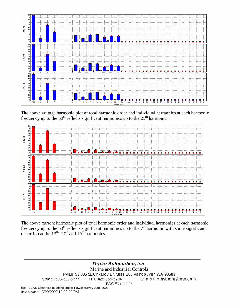
The above voltage harmonic plot of total harmonic order and individual harmonics at each harmonic frequency up to the 50th reflects significant harmonics up to the 25th harmonic.
The above current harmonic plot of total harmonic order and individual harmonics at each harmonic frequency up to the 50th reflects significant harmonics up to the 7th harmonic with some significant distortion at the 13th, 17th and 19th harmonics.

Pegler Automation, Inc.
Marine and Industrial Controls PMB# 53 305 SE Chkalov Dr. Suite 103 Vancouver, WA 98683
Voice: 503-329-5377 Fax: 425-955-5704 Email:[email protected] PAGE 22 OF 25
file: USNS Observation Island Radar Power survey June 2007 date created: 6/29/2007 10:05:00 PM
Summary The X Band radar voltage distortion is within acceptable levels below 20% duty cycle. Measured waveforms reflect 2.1% harmonic distortion. This distortion is well under the recommended 5% upper limit (Per IEEE 519-1992). At 20% duty cycle harmonic distortion is 10%. This is above acceptable levels and line reactors should be installed on the feeder lines for the X Band Radar. The S Band radar voltage distortion is within acceptable levels at the main switchboard. The line reactors (Part Number M-25453) with a inductance of 0.2 mH appear to be functioning properly. Severe harmonic distortion was witnessed on the upsteam side of the reactors at the turret (Over 25%), with the filtered values reflecting 2.2% harmonic distortion at the main switchboard. This distortion is well under the recommended 5% upper limit (Per IEEE 519-1992). The current distortions witnessed are outside of the normally acceptable levels delineated in IEEE 519-1992 Standards. High levels of harmonic current distortions can cause serious problems in the power generation systems. The current distortion from the X Band radar is approximately 77 amps 5th harmonic) at full load (20% duty cycle). With a THD of greater than 32% The current distortion from the Stbd S Band Radar is approximately 92 amps at the 5th harmonic at full load (6% duty cycle) The Port S Band Radar current distortion is similar. THD is over 20% The compensating harmonic current which would need to be injected to correct distortion is approximately 250 amps of 5th harmonic current. To better understand harmonic distortion and the effects it has on the power distribution the following explainations are provided. Power quality relates to the amplitude, frequency and distortion of the power supply system. The frequency of a power supply system is largely controlled by the prime movers. In the case of the Observation Island these are three 1800 KW turbine generators. Linear loads such as induction motors draw a sinusoidal current which follows the shape of the applied voltage. Non linear loads such as IGBT’s(Insulated Gate Bipolar Transistor), UPS’s, high efficiency fluorescent lighting and the like draw current from the source which does not follow voltage waveform applied. As a matter of definition any load which does not draw a sinusoidal current when excited by a sinusoidal voltage of the same frequency is termed a non linear load. Harmonic sources The major non linear loads which were evaluated on the Observation Island included the Bow Thruster DC Drive and the S and X Band Radars. These systems employ six pulse rectifiers (IBGT’s) which convert the applied AC waveform into DC. It is well known that these non linear loads introduce harmonics back into the power supply systems due to their inherent switching principles. IBGT’s force conduction only for certain periods of the power cycle. At low loads the harmonic distortion is much higher as a percentage of the total current draw for the device, but the current draw is much lower in regards to the total system load.

Pegler Automation, Inc.
Marine and Industrial Controls PMB# 53 305 SE Chkalov Dr. Suite 103 Vancouver, WA 98683
Voice: 503-329-5377 Fax: 425-955-5704 Email:[email protected] PAGE 23 OF 25
file: USNS Observation Island Radar Power survey June 2007 date created: 6/29/2007 10:05:00 PM
As the load goes up on the non linear load, the IBGT’s turn on for more percentage of the AC cycle, thereby reducing the overall THD of the load, but increase the THD as a percentage of total system load. The Bow Thruster system has a Harmonic Trap filter employed which has been proven to effectively limit the introduction of unwanted harmonics back into the Power Supply System form the Bow Thruster DC Drive. Effects of Harmonics The degree to which harmonics can be tolerated by the various loads of a power supply system is determined by the type of equipment the load is. The least susceptible type of load would be a resistive or heating load such as a furnace or oven. In this case the harmonic energy is generally utilized and as such the load suffers no detrimental effects of the harmonics. The most susceptible type of equipment is that whose design assumes a nearly perfect sinusoidal fundamental input. This equipment is frequently in the category of communication or data processing equipment. The type of loads which normally fall between these two extremes is the motor load. Most motor loads are relatively tolerant of harmonics. Even in the case of the least susceptible equipment, harmonics can be harmful. In the case of an oven, for example, they can cause dielectric thermal or voltage stress, wich causes premature aging of electrical insulation. In the case of motors and generators a major effect of harmonic voltages and currents is increased heating due to iron and copper losses at the harmonic frequencies. The harmonic components thus affect the machine efficiency, and can also effect the torque developed. Harmonic currents in a motor can give rise to a higher audible noise emission as compared to sinusoidal excitation. The harmonics produce a resultant flux distribution in the air gap, which can cause or enhance phenomena called “cogging” (refusal to start smoothly) or “crawling” (very high slip) in induction motors. Harmonic pairs, such as the 5th and 7th harmonics, have the potential for creating mechanical oscillations in a turbine generator combination. The mechanical oscillations result when oscillating torques, caused by interaction between harmonic currents and the fundamental frequency magnetic field, excite a mechanical resonant frequency. For instance, the 5th and 7th harmonics can combine to produce a torsional stimulus on a generator rotor at the 6th harmonic frequency. If the frequency of a mechanical resonance exists close to the frequency of electrical stimulus, high stress mechanical forces can be developed. Table 1 defines the characteristic harmonic orders derived from a six pulse converter and implies the effect when applied to the terminals of a rotating machine. Each harmonic voltage, the 5th, 7th, 11th etc. will induce a corresponding harmonic current in the stator of the machine. Each of these harmonics is a positive or negative sequence symmetrical component of the total current. These currents will induce additional heating in the stator windings, thus adding to the temperature rise caused by the fundamental current.

Pegler Automation, Inc.
Marine and Industrial Controls PMB# 53 305 SE Chkalov Dr. Suite 103 Vancouver, WA 98683
Voice: 503-329-5377 Fax: 425-955-5704 Email:[email protected] PAGE 24 OF 25
file: USNS Observation Island Radar Power survey June 2007 date created: 6/29/2007 10:05:00 PM
Table 1 - Six Pulse Converter Harmonic
Harmonic Order
Frequency HZ
Sequence Network
Stator Harmonic
Harmonic Rotation
Rotor Harmonic
1 60 + 1 Forward - 5 300 - 5 Backward 6 7 420 + 7 Forward 6
11 660 - 11 Backward 12 13 780 + 13 Forward 12 17 1020 - 17 Backward 18 19 1140 + 19 Forward 18 23 1380 - 23 Backward 24 25 1500 + 25 Forward 24
Another generally greater concern is the flow of harmonic currents in the rotor. The flow of each current in the stator will produce a magnetomotive force in the air gap that will induce current flow in the rotor of the machine. Just as each characteristic harmonic can be defined as being a negative or positive sequence, the rotation of that harmonic will be forward or backward with respect to rotor rotation. Thus from a rotor heating standpoint the 5th and 7th harmonics in the stator combine to produce a 6th harmonic current in the rotor. The 11th and 13th harmonic act in the same manner to produce a 12th harmonic current and so on with the higher order harmonic pairs. There are two major concerns with these rotor harmonics:
1) Resultant rotor heating. 2) Pulsating or reduced torques.
The amount of rotor heating that can be tolerated, as well as the amount that is incurred in a given case, depends on the type of rotor involved. Wound rotor machinery is more likely to be more seriously affected than squirrel –cage rotor machinery. Winding losses generally are of more concern than iron losses. The sum effect of the harmonics is a reduction in efficiency and life of the machinery. Effects of harmonics in Electronic equipment Power electronic equipment is susceptible to misoperation caused by harmonic distortion. This equipment is often dependent upon accurate determination of voltage zero crossings or aspects of the voltage waveform. Harmonic distortion can result in the shifting of the voltage zero crossing or the point at which one phase to phase voltage becomes greater than another phase to phase voltage. These are both critical points for many types of electronic circuit controls, and misoperation can result from these shifts. Other types of equipment such as computers and programmable logic controllers require ac sources that have no more than 5% harmonic voltage distortion factor, with the largest single harmonic being no more than 3%of the fundamental voltage. Instruments can be affected similarly, giving erroneous data or otherwise performing unpredicatably. Less dramatic interference effects of harmonics can be observed in radio and television equipment, as well as video and audio reproduction systems.
Pegler Automation, Inc.
Marine and Industrial Controls PMB# 53 305 SE Chkalov Dr. Suite 103 Vancouver, WA 98683
Voice: 503-329-5377 Fax: 425-955-5704 Email:[email protected] PAGE 25 OF 25
file: USNS Observation Island Radar Power survey June 2007 date created: 6/29/2007 10:05:00 PM
Acceptable Limits of Harmonic Current For General Distribution systems Generally the maximum harmonic current distortion allowed in a power supply system from any load is defined by the equation: Isc/IL Where: Isc = maximum short circuit current at the point of common coupling (PCC) IL = maximum demand load current (fundamental frequency component) at PCC The total demand distortion (TDD) is limited to 5% per table 10-3 of IEEE 519-1992 Where Isc/IL <20. For our examples Isc = 5000 amps/500 amps = 10 Per the same requirements Current distortions which result in a DC offset e.g. half wave converters are not allowed. The harmonic current distortion witnessed on board the USNS Observation Island exceeds recommended standard allowed limits and some mitigation should be performed. Numerous techniques for harmonic mitigation are currently being deployed, although the active filter is probably the best solution for the Observation Island. The ABB Power LV Active Filter would probably solve most of the harmonics issues, but can in itself create problems with resonance, and therefore should be studied very closely before a system is installed. Due to the nature of the fast transients of the harmonic loads the Active filter may actually contribute negatively to the power supply systems and create additional new problems which were not currently being experienced. i Reference material
For Pegler Automation, Inc.: i IEEE Stbd 519-1992