Embed Size (px)
Citation preview

Using UML to Model Relational Database Operations
Eunjee Song Shuxin Yin Indrakshi RayComputer Science Department
Colorado State UniversityFort Collins, CO 80523, USA
Email:�song, yin, iray � @cs.colostate.edu
AbstractThe Unified Modeling Language (UML) is being used as the de-facto standard in the soft-
ware industry. With the adoption of UML 2.0, the new enhancements allow this version todescribe many of the elements found in today’s software technology as well as Model DrivenArchitecture and Service-Oriented Architecture. Although OMG has released several UMLProfiles to tailor the language to specific areas, relational database modeling is not fully ad-dressed in these profiles. Many existing software applications involve complex applicationlayer implemented in object-oriented programming languages and at the same time use rela-tional database systems as the back-end data store. Modeling the whole system in a consistentmanner will help developers and end users better understand the application. In this work weshow how to model relational database operations using UML. Atomic database operationsare modeled based on our framework and are used as building blocks to model more complexdatabase operations.
1 Introduction
As software applications become more and more complicated, it is essential to capture the re-quirements, model the system design in different phases, and communicate frequently among endusers, business analysts and developers. Object-oriented technology such as Java and .NET playsan important role in software development. A lot of these applications are designed to processhuge amount of information which is saved in database system. Although object-oriented databasemanagement system (OODBMS) is gaining market share, relational database management system(RDBMS) remains the dominant database technology. Most database vendors add object-orientedfeatures into existing RDBMS products instead of totally abandoning RDBMS. Many software pro-fessionals have to continue to design or maintain this kind of hybrid system with application layerimplemented using object-oriented languages and database layer implemented using RDBMS. Howto model the whole system in a consistent manner is still a challenge because there is no universalmodeling standard for both object-oriented languages and RDBMS.
1

Relational database systems play an important role in enterprise software applications. Manyvendors add their own extensions to ANSI SQL such as Oracle PL/SQL and Microsoft TransactSQL. Data warehouse is widely used in many large and medium-sized enterprises. Business infor-mation and data are processed and manipulated at database level before being used by applications.These database operations implemented in packages, stored procedures, triggers and functions canbe very complex. Modeling these operations improves understandability, reusability and mainte-nance of the database system. It is also a way to document the dynamic aspect of database system.Entity-Relation (ER) modeling only captures the static schema and can not model dynamic opera-tions. Current UML modeling standard does not fully address this problem as well.
Most software projects involve end users, business analysts, application development team anddatabase team; modeling the whole system using one standard will make communication amongteam members much easier. Collaboration and cooperation has always been a key aspect of overallsystem success. The UML gives us the ability to model, in a single language, the business, applica-tion, database, and architecture of the system. By having one single language, everybody involvedcan communicate their thoughts, ideas, and requirements [13].
UML Data Modeling Profile [1, 9] was proposed by Rational Software from IBM. The use ofData Modeling Profile has resulted in using UML in database design [13]. UML can be used tomodel relational database schema and it is more expressive than ER modeling. Yet the currentUML database modeling techniques mainly focus on static schema modeling. Dynamic databaseoperations are modeled in an ad hoc manner.
Our previous work [21] identified the weakness of UML Data Modeling Profile, that is, lack ofabilities to model operations. We proposed a framework on how to model operations at databaselevel so that we could have a more comprehensive understanding of the whole system. We showedhow to model atomic operations in SQL Data Manipulation Language (DML) based on relationalalgebra and set theory. However, we modeled the operations at a very high-level of abstraction. Inthis paper, we model operations at a much lower-level. This will give the application developers abetter idea about the semantics of the operations. We also describe many different types of queryoperations since these operations are complex and are most frequently used.
SQL is a declarative language; it allows us to express what we want instead of specifying howto do it [10]. In contrast, procedural languages use statements to tell the computer exactly what todo in a step-wise fashion. SQL is more flexible than procedural languages since it hides internalimplementation details. We are not trying to model the internal execution details such as parsingSQL statement, validating the statement, optimizing the statement, generating an execution plan andexecuting the execution plan. All these details should not be exposed to application developers. Onthe other hand, modeling database operations at SQL statement level makes it easier for end userswho are unfamiliar with SQL key words to understand the database operations.
The remainder of this paper is organized as follows. We briefly describe ER and UML modeling
2

in Section 2. In Section 3 we discuss related work including UML Data Modeling Profile. Wepropose a framework of atomic database operation modeling in Section 4. We describe how tomodel complex database operations using the proposed framework in Section 5. Finally we presentour conclusions in Section 6.
2 Overview of ER Modeling and UML
The Entity-Relationship (ER) model was originally proposed in 1976 [5] as a way to unify thenetwork and relational database views. Essentially the ER model is a conceptual data model thatviews the real world as entities and relationships. The basic constructs in ER model are the entities,attributes and relationships, all of which may be presented in an ER diagram. The ER model hasbeen adopted as the meta-model for the ANSI Standard in Information Resource Directory System(IRDS).
The ER model focuses on conceptual and logical design phase of database but cannot capturedynamic behavior of database systems. This limitation does not prevent ER Model from beinga good modeling tool since most database systems are data centric and operations are moved tobusiness logic and application level. Later extensions to ER Model added the capability to capturemore information, such as aggregation and inheritance [4, 17].
The Unified Modeling Language (UML) [19] is a general-purpose visual modeling languagethat is used to specify, visualize, analyze, and document the artifacts of a software system [16].It captures decisions and understanding about systems that must be constructed. It is used to un-derstand, design, browse, configure, maintain, and control information about systems. UML2.0represents the biggest change that has happened yet to the UML. Within UML, there have beensignificant changes to the UML meta-model that defines the concepts of the language [8].
The UML 2.0 defines two major kinds of diagram types: structure diagrams and behavior dia-grams [16]. The static structure of a system is expressed using various kinds of diagrams, such asclass diagram, component diagram, composite structure diagram, deployment diagram, object dia-gram and package diagram. The dynamic behavior of a system is expressed using activity diagram,communication diagram, interaction overview diagram, state machine diagram, sequence diagram,timing diagram and use case diagram. In fact, the UML class and its structure correspond closelyto the entity type and its structure in ER diagrams. In many cases, class diagrams strongly resembleER diagrams. Differences emerge mainly in the modeling of operations and relationships. All fea-tures in ER diagram can be represented in the UML class diagram. The UML class diagram is moreexpressive than ER diagram for example a stereo-typed class can be used to represent a particulartype of class, an OCL notation can be used to express pre and post conditions.
UML 2.0 supports the initiative for a model-driven architecture by providing the stable technicalinfrastructure that allows for additional automation of the software development process [7]. OMG’s
3

Model Driven Architecture provides an open, vendor neutral approach to the challenge of businessand technology [18]. Based on OMG’s established standards, the MDA separates business andapplication logic from underlying platform. Platform Independent Model (PIM) is transformed intoPlatform Specific Model (PSM) using certain transformation rules. MDA is built on top of UMLand modeling is the foundation for model transformation.
3 Related Work
There has been much research in the UML data modeling [2, 3, 11, 12, 14, 15]. Using varioustransformation techniques an ER diagram can be converted into an equivalent UML class diagram.However, almost all of the previous research focuses on static schema; none of them deals withdynamic operations at database layer. Premerlani [14] discusses the reverse engineering of RDBMSinto OMT model. His approach emphasizes on the analysis of candidate keys, rather than primarykeys. However, the reverse engineering process requires much user interactions. Ramanathan [15]presents an object-centered approach for doing the schema mapping. The procedure maps a 3NFrelational schema into an object-oriented schema without the explicit use of inclusion dependenciesand provides a greater scope for automation. Behm [3] proposes a two-phase transformation pro-cess, i.e., schema transformation followed by data migration. During the data migration process,instances of class are created, and then attributes are assigned based on a set of rules. The data map-ping process can be implemented without much user intervention. Researchers [3, 11, 12, 13, 14, 15]have also proposed techniques using which a UML class diagram can be transformed into an equiv-alent ER diagram. Other researchers have worked on techniques that convert an ER diagram to aclass diagram.
The power of the UML is not limited to object oriented software development. The UMLis being applied to many other areas of software development, such as data modeling, enhancingpractitioners’ ability to communicate their needs and assessments to the rest of the team [9]. UMLData Modeling Profile [1, 9] was proposed to apply UML to relational database modeling.
The UML can be used to describe the complete development of relational and object relationaldatabases from business requirements through the physical data model [1]. UML for Data ModelingProfile is implemented by Rational Rose Data Modeler; it includes descriptions and examples foreach concept including database, schema, table, key, index, relationship, column, constraint, triggerand stored procedures. We will list some frequently used features of Rational Data Modeler asfollows [1]:
� The stereotype ��� Database ��� , when used as a UML component, represents a database.
� A package using the ��� Schema ��� stereotype in a UML model represents a database schema.
� A class with the ��� Table ��� stereotype represents a relational table in a schema of a database.
4

� A primary key uses a PK tag in front of the column as shown, and the PK stereotyped opera-tion is the primary key constraint.
� An FK tag represents the foreign key. It generates the foreign key constraint, which is repre-sented by a stereotype FK on an operation.
� The Index stereotype on an operation represents a key constraint for an index.
� An identifying relationship is a relationship between two tables in which the child table mustcoexist with the parent table. The identifying relationship is represented with a stereotype of��� Identifying ��� .
� A non-identifying association represents a relationship between two independent tables. Thenon-identifying relationship is created with a stereotype of ��� Non-identifying ��� .
� Columns are represented as attributes. Computed columns are defined by an expression.
� All constraints are defined as stereotyped operations and primary key is a special kind ofconstraint.
� The Trigger stereotype on an operation represents the trigger on the table.
� The Unique stereotype represents the uniqueness constraint.
� Stored procedure can be represented as a stereotyped operation using ��� SP ��� . Multiplestored procedures are contained inside a stereotyped template ��� SP Container ��� . Thesignature of a stored procedure can be shown besides stored procedure name.
� Activity diagram and state machine diagram can be used to model stored procedure at ahigh level; however, no corresponding relationship is defined between tables, SQL DML andactions in activity diagram. Tables are not directly related to states in state machine diagram.
� A view is defined in the UML as a class with the stereotype of ��� View ��� .
The UML Data Profile allows application software development and data modeling with oneunified language. Figure 1 is an example of UML data model, taken from our previous work [21],generated using Rational Rose. A simplified Air Toxics Data Archive system is used as the underly-ing database. A typical air quality monitoring program involves at least monitoring sites, pollutants,sampling time and concentration values.
There are three tables in this diagram: Pollutant, Site and Concentration. They are representedusing stereotyped class. In this example, there are two stored procedures. The first stored proce-dure ReportByPollutant uses PollutantID as an input parameter; this procedure will return a result
5

set which contains all concentration information for this particular pollutant. Another stored pro-cedure ReportBySite takes a SiteID parameter; it will return a result set which contains all con-centration information at the specified site. These two stored procedures are contained in ��� SPContainer ��� template as two stereotyped operations. Although we can use activity diagram andstate machine diagram to model stored procedures, these two diagrams are used at requirementanalysis and logical design level. There is no standard technique to model low-level DML such asSELECT, DELETE, UPDATE and INSERT. In many systems, the stored procedures can be verycomplex. Major RDBMS vendors define their own extension to SQL standard and add many lan-guage constructs to represent sequential, conditional and iterative operations. Many RDBMS alsoallow user-defined functions to simplify commonly used operations. Modeling both stored proce-dures and functions in a standard way will offer great benefits to application developers, databasedevelopers and business analysts. Note that, the UML Data Profile describes the relational database.It models the database implementation; it is at a different level of abstraction than the ER diagram.
Address:varchar(50)SiteName:varchar(50)
1
PK_Pollutant()
PollutantID:INT
CASNumber:varchar(50)PollutantName:varchar(50)
<<PK>>
<<FK>><<FK>>
*
ConcentrationValue:FLOATObservationDate:DATETIME
<<PK>> PK_Concentration()
SiteID:INT
SP_1<<SP Container>>
<<SP>> ReportBySite(SiteID:INT)<<SP>> ReportByPollutant(PollutantID:INT)
PK PK
PK
Site
ConcentrationPollutant
1
Longitude:FLOATLatitude:FLOAT
<<PK>> PK_Site()
Concentration2()Concentration3()
ConcentrationID:INT
PollutantID:INTSiteID:INT
*
Figure 1: UML data model generated by Rational Rose
Using Rational Rose, we can only model stored procedures using activity diagram and statemachine diagram in an ad hoc fashion. No standard techniques are available as to how to model dy-namic operations encapsulated in stored procedures and functions at implementation level. Actionsand states are represented in plain English which will create ambiguity and confusion to differentpeople.
4 Atomic DML Operations Modeling
In this section, before showing our modeling of the relational database operations we would liketo adapt the diagram, obtained from Rational Rose and used in our earlier work [21], to explainour ideas with UML 2.0 compliance. In UML, four predefined basic types are supported: Boolean,Integer, Real, and String. Therefore, Integer and String are used instead of INT and varchar. Two
6

new data types DateTime and Float are also added to the UML class diagram. We added three otherclasses Projection, QueryResult, and JoinResult. The stereotype ��� temporary ��� indicates thatthese classes are of temporary nature - the objects of these classes get destroyed when the DMLstatement has completed execution. We added a new class TableHandler that has references toclasses representing three database tables. Figure 2 shows the details. In the following subsections,we will show how the relational database operations are modeled as operations in the TableHandler
class.
PK_Pollutant()
PollutantID:Integer
CASNumber:StringPollutantName:String
<<PK>>
11
<<FK>><<FK>>
*
ConcentrationValue:FloatObservationDate:DateTime
<<PK>> PK_Concentration()Concentration2()Concentration3()
ConcentrationID:Integer
PollutantID:IntegerSiteID:Integer
*
*
1
SP_1<<SP Container>>
<<SP>> ReportBySite(SiteID:Integer)<<SP>> ReportByPollutant(PollutantID:Integer)
...select(table:String,expr:Expression)delete(table:String,expr:Expression)
expr:Expression)update(table:String,attrVal:Set(AttrVal),
JoinResult<<temporary>>
{ordered}pollutantRef
siteRef
{ordered}
TableHandler
insert(table:String,attrVal:Set(AttrVal)) 1
{ordered}
concentrationRef
*
PK PK
ConcentrationPollutant
1
PK
Site
*
Longitude:FloatLatitude:Float
<<PK>> PK_Site()
SiteID:Integer
Address:StringSiteName:String
Projection<<temporary>>
QueryResult<<temporary>>
Float<<datatype>>
DateTime<<datatype>> Table
Figure 2: Air toxics data archive UML data model
4.1 Relational Databases
Relational databases are based on the relational model [6]. The relational model has a strong math-ematical foundation and it is based on set theory. Each relational table in a database is considered asa set and each row corresponds to an element of the set. The eight relational operations performedon the tables are union, difference, intersection, product, projection, selection, join and division.The Structured Query Language (SQL) is the most widely used language for relational databases.SQL is broadly categorized into Data Definition Language (DDL) and Data Manipulation Language(DML). DDL is used for specifying and manipulating the structure of the database and DML is usedfor performing operations on the database itself. In this paper, we focus on the SQL DML constructsonly.
7

4.2 SQL Data Manipulation Language
Database operations can be in the form of packages, stored procedures, functions, or other vendordefined language constructs. However, our modeling technique will not depend upon the formatof these operations. Essentially all database operations are implemented using atomic SQL datamanipulation language constructs such as INSERT, UPDATE, DELETE, and SELECT. In this sec-tion, we will model standard SQL DML constructs and use them as building blocks to model morecomplex operations in the next section.
We all know that there is no object in RDBMS and operations are separated from tables; whilein object-oriented programming, an object encapsulates both data and operations. In our modelwe can think of a row as an anonymous object of a class as defined by the table. There are fourpredefined operations upon this object which are INSERT, UPDATE, DELETE and SELECT.
4.3 Insert Operation Modeling
Insert statement is the simplest operation in DML. Here is an example:
INSERT INTO Pollutant (PollutantID, PollutantName, CASNumber)
VALUES (1, ’Ethylbenzene’, 100414)
An insert operation can be modeled using many different diagrams, such as sequence diagram,communication diagram, activity diagram, interaction overview diagram and state machine diagram.We show a generic form of the sequence diagram in Figure 3. This represents a sequence diagramframe that can be instantiated for each insert operation. Recall that we have a class TableHandlerthat coordinates all operations involving database tables. This class consists of a single object thatis shown as :TableHandler in Figure 3. The insert operation takes as input two parameters: tablewhich represents the name of a relational table and attrVal which is a set of attribute-value pairs. The:TableHandler selects a table reference (that is, either pollutantRef, concentrationRef, or siteRef)from the set of all tables and forwards it to the insert operation. Using this operation, :TableHandler
creates an anonymous object :Table that corresponds to a row of the table refered by the selectedtable reference (that is, either Pollutant, Concentration or Site). The insert operation does not returnanything. UML 2.0 adds a useful touch to sequence diagram. We can now frame a sequencediagram by surrounding it with a border and adding a compartment in the upper left corner. Thecompartment contains information that identifies the diagram [20]. Each framed sequence diagramcan be referred by other sequence diagrams. UML 2.0 also adds another new core construct, knownas combined fragment, which expresses control structures such as choice, loop, etc. We encapsulatethe whole statement into a named framed part called Insert. For each specific example, this genericdiagram can be instantiated according to the name of table given as the first parameter. For ourexample SQL statement, pollutantRef, a table reference to the Pollutant table, is given as an input to
8

the insert sequence diagram so that it may insert a new row to the Pollutant table as shown in Figure4. Figure 5 shows how the :TableHandler gets a table reference from the table name and invokesan insert operation to the appropriate table. The box labeled Insert represents the details shown inFigure 4.
create(attrVal:Set(AttrVal))
sd_insert(tableRef:Set(Table),attrVal:Set(AttrVal))
:TableHandler
sd_Insert
:Table
Figure 3: Insert operation sequence diagram frame
sd Insert
(CASNumber, 10414)})(PollutantName, "Ethylbenzene"), create({(PollutantID, 1),
(CASNumber, 100414)}){(PollutantID, 1), (PollutantName, "Ethylbenzene"), sd_insert(pollutantRef:Set(Pollutant),
:TableHandler
:Pollutant
Figure 4: Insert operation sequence diagram for the example
sd_insert(tableRef,{(PollutantID,1),(PollutantName,"Ehtylbenzene"),(CASNumber,"1000414")})
(CASNumber,"1000414")})(PollutantName,"Ehtylbenzene"),insert(Pollutant,{(PollutantID,1),
tableRef:=findRef("Pollutant")
Insertref
:TableHandler
Figure 5: Insert operation sequence diagram for the example
1:tableRef:=findRef("Pollutant")(PollutantName,"Ethylbenzene"),insert("Pollutant",{(PollutantID,1),
(CASNumber,1000414)})
(CASNumber,1000414)})2:create({(PollutantID,1),(PollutantName,"Ethylbenzene"),
:TableHandler
:Pollutant
Figure 6: Insert operation communication diagram
9

The communication diagram shown in Figure 6 illustrates how our example insert operation canbe represented in the form of a communication diagram. This shows that the insert operation con-sists of a single step that creates an anonymous object in the Pollutant table. The insert operation canbe represented using state machine diagram and activity diagram as well. However, these pictorialrepresentations are not very useful because a state machine diagram is good for describing behaviorof objects over time in terms of state transitions triggered by events and an activity diagram is usedfor describing the flow of control and (optionally) data.
4.4 Update Operation Modeling
The update operation can be simple like the insert operation or it can be more complex. The simpleUPDATE does not have a WHERE clause and it changes one or more attributes of all rows belongingto the table. Since this is a special case of the more complex UPDATE, we do not specify it usingUML diagrams. An example of a simple UPDATE is given below.
UPDATE Pollutant SET CASNumber = 0
The complex form of UPDATE includes the WHERE clause. In such case, an update operationcan be decomposed into the following steps: 1) Selection: find the rows to be updated based onspecific conditions first; 2) Set: update the old value with the new value in all these rows. Anexample of a more complex update operation appears below.
UPDATE Pollutant SET CASNumber = 103333
WHERE PollutantID = 2
10

ref
[get next item]
loop
Select
(a) A sequence diagram frame for UPDATE operation
selResult[i]:Table
set(attrVal:Set(AttrVal))
sd Update
selResult := select(tableRef,expr):Set(Table)
refUpdate
(b) A sequence diagram for example UPDATE statement
:TableHandlerupdate("Pollutant",
{(CASNumber,103333)},PollutantID = 2)
sd_update(tableRef,
tableRef:=findRef("Pollutant")
{(CASNumber,103333)},PollutantID = 2)
:TableHandler
sd_update(tableRef:Set(Table),attrVal:Set(AttrVal),expr:Expression)
Figure 7: Update operation sequence diagram
Figure 7 describes UPDATE using sequence diagrams. In the above example, we use a framedpart update to represent the update statement as a whole and use select to implement the selectionpart of the statement. The details of how SELECT is implemented will be discussed later. Figure7(a) represents a generic diagram of the update operation. The update operation takes in three pa-rameters, namely, tableRef which is the reference to the table that must be updated, attrVal whichis the set of attribute-value pairs (describing the attributes that must be updated and their modifiedvalues), and expr which is an expression needed to select the rows that needs updates. The :Table-
Handler on receiving this operation executes a select operation on it. The select operation returnsselResult which is a set of rows of tableRef satisfying the condition stated in expr. For each row re-turned by selResult, indicated by selResult[i], the attributes listed in attrVal must be modified to thecorresponding values. Figure 7(b) shows that the :TableHandler selects the table tableRef accordingto the table name passed as the first parameter and invokes the update operation on the Pollutant
table.The communication diagram for our specific example UPDATE is shown in Figure 8. The
communication diagram shows the three steps involved in the update operation. The first step,labeled with 1, involves selecting the table Pollutant referenced in the update operation. The nextstep involves finding the rows in the selected table that satisfy the expression PollutantId = 2. Thelast step is applied to several rows that were selected in the previous step. This is indicated by the
11

label 3 � shown in the figure. This step involves updating the CASNumber to the new value 103333.
1: tableRef:=findRef("Pollutant")
update("Pollutant",{(CASNumber,103333)},PollutantID = 2)
selResult[i]:Pollutant
3*[for all i]: set({(CASNumber,103333)})
2: selResult:= sd_select(tableRef,PollutantID =2):Set(Pollutant)
:TableHandler
Figure 8: Update operation communication diagram
4.5 Delete Operation Modeling
Delete operation is similar to update operation except that the rows are removed from the tableinstead of being updated. A typical DELETE statement is listed below and its sequence diagramand communication diagram are shown in Figure 9 and Figure 10. Note that the sequence diagramis very similar to that of the update operation except that there is an X marked at the end of thelifeline which indicates that the selected row is being destroyed.
DELETE FROM Pollutant WHERE PollutantID = 11
12

ref
:TableHandler
Select
delete()[get next item]
expr:Expression)
sd Delete
sd_delete(tableRef:Set(Table),
selResult[i]:Table
PollutantID = 2)delete("Pollutant",
(a) A sequence diagram frame for DELETE operation
selResult:= select(tableRef:Set(Table),expr:Expression):Set(Table)
tableRef:=findRef("Pollutant")
sd_delete(tableRef, PollutantID = 2)
(b) A sequence diagram for the example DELETE statement
refDelete
loop
:TableHandler
Figure 9: Delete operation sequence diagram
1: tableRef:= findRef("Pollutant")2: selResult:= sd_select(tableRef,PollutantID =2):Set(Pollutant)
selResult[i]:Pollutant
delete("Pollutant",PollutantID = 2)
3*[for all i]: delete()
:TableHandler
Figure 10: Delete operation communication diagram
4.6 Select Operation Modeling
Select operation is the most important operation in a database system and it can often be extremelycomplex. However, it does not change the database.
In the following we describe some of the most commonly used SELECT statements. We startwith a simple select that retrieves all the attributes of a table. We call this the SelectSimple operation.This is shown in Figure 11(a). It takes in two parameters: tableRef which is the reference to thetable that must be selected and expr which is an expression defined on the attributes of the table.The :TableHandler selects table tableRef. For each row of tableRef, indicated by tableRef[i], it gets
13
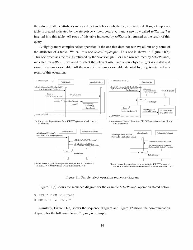
the values of all the attributes indicated by t and checks whether expr is satisfied. If so, a temporarytable is created indicated by the stereotype ��� temporary ��� , and a new row called selResult[j] isinserted into this table. All rows of this table indicated by selResult is returned as the result of thisquery.
A slightly more complex select operation is the one that does not retrieve all but only some ofthe attributes of a table. We call this one SelectProjSimple. This one is shown in Figure 11(b).This one processes the results returned by the SelectSimple. For each row returned by SelectSimple,indicated by selResult, we need to select the relevant attrs, and a new object proj[i] is created andstored in a temporary table. All the rows of this temporary table, denoted by proj, is returned as aresult of this operation.
PollutantID = 2):Set(Projection)sd_selectProjSimple(tableRef,
PollutantID = 2):Set(Projection)
tableRef:=findRef("Pollutant")
selectProjSimple("Pollutant",
loop<<temporary>>proj[i]:Projection
createProjection (selResult[i],attrs) [for each selResult[i]]
return projreturn selResult
:QueryResult
<<temporary>>selResult[j]
(a) A sequence diagram frame for a SELECT operation which retrievesall attributes
(tableRef,expr)
sd_selectProjSimple(tableRef:Set(Table),
sd SelectSimple
sd_selectSimple(tableRef: Set(Table),expr: Expression): Set(Table)
t:= get():Table
opt
loop
create(t)
[CheckExpr(t,expr) = true]
[for each tableRef[i]]
sd SelectProjSimple
sd_selectSimpleselResult:=:Set(Projection)
expr:Expression, attrs:AttributeList)
Pollutant[i]:Pollutant
(b) A sequence diagram frame for a SELECT operation which retrieves
"SELECT * FROM Pollutant WHERE PollutantID = 2"(c) A sequence diagram that represents a simple SELECT statement
"SELECT PollutantName FROM Pollutant WHERE PollutantID = 2"(d) A sequence diagram that represents a simple SELECT statement
:TableHandler
refSelectSimple
a list of attributes
:TableHandler :TableHandlertableRef[i]:Table
refSelectSimple
tableRef[i]:Table
refSelectSimple
Pollutant[i]:Pollutant
PollutantID = 2):Set(QueryResult)sd_selectSimple(tableRef,
PollutantID = 2):Set(QueryResult)
tableRef:=findRef("Pollutant")
selectSimple("Pollutant", :TableHandler
Figure 11: Simple select operation sequence diagram
Figure 11(c) shows the sequence diagram for the example SelectSimple operation stated below.
SELECT * FROM Pollutant
WHERE PollutantID = 2
Similarly, Figure 11(d) shows the sequence diagram and Figure 12 shows the communicationdiagram for the following SelectProjSimple example.
14

SELECT PollutantName
FROM Pollutant
WHERE PollutantID = 2
Note that SelectSimple and SelectProjSimple queries involve a single table and the WHEREclause is a boolean expression over the attributes of this single table. Later on, we show how toovercome this shortcoming.
createProjection(p[i],PollutantName)
1: tableRef:= findRef("Pollutant")PollutantName):Set(Projection)
:Set(Pollutant)2: selResult:= sd_selectSimple(tableRef,PollutantID =2)
3*[for each i]:
selectProjSimple("Pollutant",PollutantID=2,
proj[i]:Projection<<projection>>
:TableHandler
Figure 12: Select statement communication diagram
A query can itself include one or more subqueries. Any number of subqueries can be nested ina statement. An example of a query having a nested query is given below.
SELECT * FROM Concentration C
WHERE C.PollutantID IN
(SELECT PollutantID FROM Pollutant P
WHERE P.PollutantName LIKE ’A%’)
The nested queries are described in Figure 13. In the sequence diagram frames, we use tableRef andexpr to denote the table and the where clause referenced in the query, respectively. We use tableRef2,expr2, and attr2 to denote the table, where clause, and attributes referenced in the subquery. Figure13(a) shows nested subqueries corresponding to the SELECT operation that selects all attributesfrom a table. We call this specification Select. The optional aspect of the subquery is depicted usingthe alt label. When there are no subqueries (corresponding to the top half of the alt), the result ofSelectSimple is returned. Otherwise, the execution corresponds to the bottom half of the alt box.First, the subquery is executed. The subquery typically selects the attributes attr2 of table tableRef2
for rows which satisfy expr2. Since expr2 can be complex involving other nested queries, thesubquery is processed by SelectProj. The subquery returns the expression proj. A new expressionis created involving the result returned by the subquery and the original expression. This is denotedin the figure as newexpr:=SelectExpr(proj,expr). This newexpr then becomes an input to the query.The query is handled by SelectSimple which returns all the attributes of the rows satisfying newexprin tableRef. Figure 13(b) shows the sequence diagram frame of a query that selects some attributes
15

from a table and has a subquery. Figures 13(c) and 13(d) show specific examples of SELECT havingnested queries.
refSelectSimple
:TableHandler :TableHandler
return selResult
return selResult
alt
return proj
proj:=sd_selectProjSimple(tableRef,newexpr,
:Set(Projection)
[subqueries]
return proj
:Expressionnewexpr:=selectExpr(expr,proj2)
refSelectProjSimple
refSelectProjSelectProj
sd Select
[no subqueries]
selResult:=sd_selectSimple(tableRef,expr)
alt
selResult:=sd_selectSimple(tableRef,newexpr)
:Set(Projection)proj:=sd_selectProj(tableRef2,expr2,attrs2)
[subqueries]
:Expressionnewexpr:=selectExpr(expr,proj)
refSelectSimple
ref
ref
attrs:AttributeList)
SelectProjref
tableRef:=findRef("Concentration") tableRef:=findRef("Concentration")
ref
expr: C.PollutantID IN (SELECT PollutantID FROMPollutant P WHERE P.PollutantName LIKE ’A%’)
expr:Expression)
attrs2: PollutantIDexpr2: P.PollutantName LIKE ’A%’tableRef2:findRef("Pollutant")
attrs2: PollutantIDexpr2: P.PollutantName LIKE ’A%’tableRef2:findRef("Pollutant")attrs: PollutantID
Pollutant P WHERE P.PollutantName LIKE ’A%’)expr: C.PollutantID IN (SELECT PollutantID FROM
expr:Expression,sd_selectProj(tableRef,
SelectProjSimple
:Set(Projection)expr:Expression,attrs:AttributeList)sd_selectProj(tableRef:Set(Table),
sd SelectProj
proj:=sd_selectProjSimple(tableRef,expr,attrs):Set(Projection)
[no subqueries]
proj2:=sd_selectProj(tableRef2,expr2,attrs2)
attrs):Set(Projection)
:Set(QueryResult)
:Set(QueryResult)
sd_select(tableRef:Set(Table),expr:Expression):Set(QueryResult)
(a) A sequence diagram frame for SELECT operationthat selects all attributes and has subquery
(b) A sequence diagram frame for SELECT operationthat selects some attributes and has subquery
sd_select(tableRef,
:TableHandler :TableHandler
Select
attrs:AttributeList):Set(Projection)
selectProj("Concentration",expr:Expression,select("Concentration",
expr:Expression):Set(QueryResult)
PollutantID FROM Pollutant P WHERE P.PollutantName LIKE ’A%’)"
(c) A sequence diagram that represents a SELECT statement with a subquery:"SELECT * FROM Concentration C WHERE C.PollutantID IN (SELECT
(SELECT PollutantID FROM Pollutant P WHERE P.PollutantName LIKE ’A%’)"
(d) A sequence diagram that represents a SELECT statement with a subquery:"SELECT PollutantID FROM Concentration C WHERE C.PollutantID IN
Figure 13: Subquery operation sequence diagram
16

ref
sd_selectProj(joinResult, true,selResult:=
expr:Expression): Set(QueryResult)tableRef2:Set(Table2),attrs2:AttributeList,
sd_selectInnerJoin(tableRef1:Set(Table1),attrs1:AttributeList,
Table2.attrs2 FROM Table1, Table2 WHERE expr")(a) A sequence diagram frame for an (INNER) JOIN operation: "SELECT Table1,attrs1,
sd SelectInnerJoin
attrs1,attrs2):Set(QueryResult)
return selResult
InnerJoin
selectInnerJoin("Pollutant",attrs1"Concentration",attrs2,expr)
SelectProj
expr):Set(JoinResult)(tableRef1,tableRef2,joinResult:=sd_innerJoin
:TableHandler
tableRef2,attrs2,expr)sd_selectInnerJoin(tableRef1,attr1,
tableRef2:=findRef("Concentration")
SelectInnerJoinref
tableRef1:=findRef("Pollutant")
:Set(QueryResult)
:JoinResultjoined[k]
<<temporary>>
return joined
createJoinedObject(t1,t2)
[CheckExpr(t1,t2,expr) = true]
t1:=get():Table1
t2:=get():Table2[for each tableRef2[j]]
[for each tableRef1[i]]
:TableHandlersd InnerJoin
ref
attrs1: P.PollutantName
WHERE C.PollutantID = P.PollutantIDFROM Concentration C, Pollutant PSELECT P.PollutantName, C.ObsevationDate, C.SiteID, C.ConcentrationValue
(b) A sequence diagram that represents a SELECT statement with INNER JOIN:
expr:Expression): Set(JoinResult)tableRef2:Set(Table2),
sd_innerJoin(tableRef1:Set(Table1),
tableRef2[i]:Table2
opt
loop
loop
tableRef1[i]:Table1
:TableHandler
expr: C.PollutantID = P.PollutantIDattrs2: C.ObservationDate;C.SiteID;C.ConcentrationValue
Figure 14: Sequence diagram for SELECT statement containing JOIN operation
17

Another complexity in SELECT statements arises when they have JOIN operations. Below wegive an example of such a statement.
SELECT P.PollutantName, C.ObservationDate,
C.SiteID, C.ConcentrationValue
FROM Concentration C, Pollutant P
WHERE C.PollutantID = P.PollutantID
The sequence diagram for the inner join operation is described in Figure 14(a). The SELECTstatement containing a JOIN operation is processed in two steps as shown in the top part of Figure14(a). First, an inner join operation is performed on the two tables, denoted by tableRef1 andtableRef2, using the expression expr. The result, denoted as joinResult, is the input to the SelectProjoperation. This operation selects attrs1 and attrs2 from joinResult and returns it to the user. Thedetails of the inner join operation are given in the bottom part of Figure 14(a). The inner joinoperation is submitted to the :TableHandler. The :TableHandler selects tableRef1 and tableRef2
from the set of all tables. For each row of tableRef1, denoted by tableRef1[i], all the attributesare fetched. Similarly, for each row in tableRef2, denoted by tableRef2[j], all the attributes arefetched. The attributes are matched according to the conditions expr. If the conditions are satisfied,a temporary object called joined[k] is created. The process is repeated for all rows in tableRef1 andtableRef2 which is indicated by the loop boxes shown in the figure. An example inner join statementis shown in Figure 14. The outer join operations can also be modeled in a similar manner.
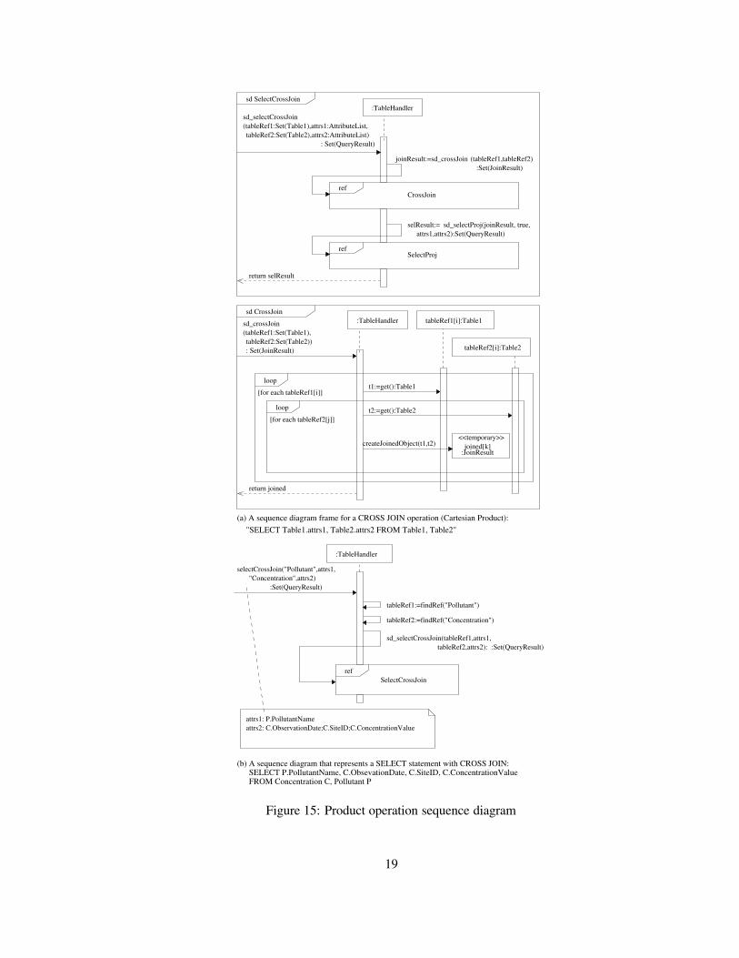
Related to the join operation is the cartesian product. Here is an example statement describingcartesian product.
SELECT P.PollutantName, S.SiteName
FROM Pollutant P, Site S
The detailed sequence diagram is given in Figure 15. The top part of Figure 15(a) is similar tothat of the inner join. The main difference is in how the cartesian product is implemented whichis shown in the bottom part of Figure 15(a). Here again, each row in tableRef1 and each row intableRef2 are joined together to create a temporary object. However, unlike the join operation, therows are always merged and no expression is checked before merging them.
18
ref
CrossJoinref
sd_selectProj(joinResult, true,selResult:=
tableRef2:Set(Table2),attrs2:AttributeList)
sd_selectCrossJoin
"SELECT Table1.attrs1, Table2.attrs2 FROM Table1, Table2"
sd SelectCrossJoin
attrs1,attrs2):Set(QueryResult)
return selResult
sd CrossJoin
SelectProj
:Set(JoinResult)(tableRef1,tableRef2)joinResult:=sd_crossJoin
SelectCrossJoinref
:Set(QueryResult)tableRef2,attrs2):sd_selectCrossJoin(tableRef1,attrs1,
tableRef2:=findRef("Concentration")
tableRef1:=findRef("Pollutant")
:Set(QueryResult)"Concentration",attrs2)
selectCrossJoin("Pollutant",attrs1,
(tableRef1:Set(Table1),attrs1:AttributeList,
:TableHandler
(a) A sequence diagram frame for a CROSS JOIN operation (Cartesian Product):
createJoinedObject(t1,t2)
: Set(QueryResult)
return joined
t1:=get():Table1
t2:=get():Table2[for each tableRef2[j]]
[for each tableRef1[i]]
:TableHandler
attrs2: C.ObservationDate;C.SiteID;C.ConcentrationValueattrs1: P.PollutantName
:JoinResultjoined[k]
<<temporary>>
tableRef2[i]:Table2
loop
loop
: Set(JoinResult)tableRef2:Set(Table2))
sd_crossJoin(tableRef1:Set(Table1),
tableRef1[i]:Table1
:TableHandler
(b) A sequence diagram that represents a SELECT statement with CROSS JOIN:
FROM Concentration C, Pollutant PSELECT P.PollutantName, C.ObsevationDate, C.SiteID, C.ConcentrationValue
Figure 15: Product operation sequence diagram
19

Union operator can combine two union-compatible queries. Its semantic meaning is the samethat in relational theory. We can model union operation as shown in Figure 16. The first stepinvolves performing a select on tableRef1 that is indicated by a SelectProj operation. The resultthat is returned is denoted by selResult1. The second step involves performing a select on tableRef2
using the SelectProj operation. This select operation returns selResult2. Each row returned inselResult2, denoted by selResult2[i], is inserted into selResult1 using the insert operation. Theresulting selResult1 is returned to the user.
SELECT PollutantID FROM Pollutant
WHERE PollutantName LIKE ’A%’
UNION
SELECT PollutantID FROM Pollutant
WHERE PollutantName LIKE ’B%’
20

sd_selectProj(tableRef1,expr1,attrs):Set(QueryResult)
ref
(a) A sequence diagram frame for a UNION operation: "SELECT attrs FROM Table1 WHERE expr1 UNION SELECT attrs FROM Table2 WHERE expr2"
expr2,attrs):Set(QueryResult)
: Set(QueryResult)attrs:AttributeList)expr2:Expression,tableRef2:Set(Table2),expr1:Expression,
(tableRef1:Set(Table1),sd_selectUnion
sd SelectUnion
tableRef2:=findRef("Concentration")
tableRef1:=findRef("Pollutant")
:TableHandler
selResult1:=
return selResult1
[for each selResult2[i]]
selResult1[i]:QueryResult
Insertref
sd_insert(selResult1,attrVal):Set(QueryResult)
attrVal:=getAttrValues():AttrVal
SelectProj
SelectProjref
selResult2:=sd_selectProj(tableRef2,
attrs: PollutantIDexpr2: PollutantName LIKE ’B%’expr1: PollutantName LIKE ’A%’
:Set(QueryResult)expr1,tableRef2,expr2,attrs)
sd_selectUnion(tableRef1,
SelectUnionref
:TableHandler
loop
selResult2[i]:QueryResult
:Set(QueryResult)expr1,"Concentration",expr2,attrs)
selectUnion("Pollutant",
(b) A sequence diagram that represents a UNION statement:
LIKE ’A%’ UNION SELECT PollutantID FROM PollutantWHERE PollutantName LIKE ’B%’"
SELECT PollutantID FROM Pollutant WHERE PollutantName
Figure 16: Union operation sequence diagram
The difference operation can be represented in various ways. Here is an example.
SELECT P.PollutantName
FROM Pollutant P
WHERE NOT EXISTS
(SELECT *
21

FROM Concentration C
WHERE P.PollutantID = C.PollutantID)
The semantic meaning of this query is to find all pollutant names which are not listed in Concen-tration table. This query essentially represents a “Difference” operation and its sequence diagram isshown in Figure 17. This query makes use of nested queries. Consequently, we use our previouslydefined constructs to model this operation.
WHERE P.PollutantID = C.PollutantID)expr: NOT EXISTS (SELECT * FROM Concentration C
"SELECT P.PollutantName FROM Pollutant P WHERE NOT EXISTS
attrs2: *expr2: P.PollutantID = C.PollutantIDattrs: P.PollutantName
(SELECT * FROM Concentration C WHERE P.PollutantID = C.PollutantID"
A sequence diagram that represents a SELECT statement with a subquery:
expr:Expression,selectProj("Pollutant",
SelectProjref:Set(Projection)
attrs:AttributeList)
:TableHandler
Figure 17: Difference operation sequence diagram
5 Relational Database Operation Modeling
Most database products define functions, packages, and stored procedures to isolate portions ofoperations, hide implementation details and improve performance. These operations can be verycomplex and should be modeled the same as application level operations. No single diagram canmodel every aspect of a system. We can use a use case to represent an operation at requirementanalysis level and use activity diagram, sequence diagram, communication diagram and state ma-chine diagram at design and implementation level. On the other hand, we don’t have to use alldiagrams as long as we can clearly model the target system. Essentially, no matter how complexa database operation might be, it is composed of basic DML statement and SQL extension such asTransact-SQL or PL/SQL. We can use OO modeling techniques to model these language constructs.The use case template for an operation can be specified as shown in Table 1.
In this section, we will use a stored procedure as an example to demonstrate the techniques tomodel relatively complex database operations. Here is a system stored procedure dt setpropertybyidused in SQL Server 7.0. It is implemented in Transact-SQL. Transact-SQL allows one to performa series of database operations such as inserting, updatating, and/or deleting darabase records withconditions or iterations as needed. It is quite similar to a procedural programming language.
22

Operation Name Give the name of the operationOwner Give the owner of the operationOperation Type Stored procedure, function, package, etc.Involved Tables List all tables used in this operationOverview A brief description of the operationPrecondition Describe the precondition of the operation in OCL format,
SQL expression or English statements.Post Condition Describe the post condition of this operationInput Parameters List all input parameters including name and data typeOutput Parameters List all output parameters including name and data typeReturn Value Give the return type
Table 1: Use case template for operations
CREATE PROCEDURE dbo.dt_setpropertybyid
@id int,
@property varchar(64),
@value varchar(255),
@lvalue image
as
set nocount on
if exists (SELECT * FROM dbo.dtproperties
WHERE objectid=@id AND property=@property)
begin
UPDATE dbo.dtproperties
SET value=@value, lvalue=@lvalue, version=version+1
WHERE objectid=@id AND property=@property
end
else
begin
INSERT dbo.dtproperties (property, objectid,
value, lvalue)
VALUES (@property, @id, @value, @lvalue)
end
The above stored procedure can be modeled using use case as shown in Table 2. The use casetemplate might vary slightly depending upon the specific RDBMS products.
We can use activity diagram, sequence diagram and other diagrams to model this stored proce-dure at requirement, analysis, design and implementation level. By combining all these diagramstogether, we will have a much better understanding of complex database operations.
23

Operation Name dt setpropertybyidOwner dboOperation type Stored procedureInvolved Tables dtpropertiesOverview If the property already exists, reset the value; otherwise add property.Precondition dtproperties table has been createdPost Condition A new record is added into dtproperties table
if the property already exists; otherwise, reset the property.Input Parameters @id int, @property varchar(64), @value varchar(255), @lvalue imageOutput Parameters NoneReturn Value None
Table 2: Use case of dt setpropertybyid
[property doesn’t exist]
[property exists]
Check property
Insert propertyUpdate property, version ++
Figure 18: Stored procedure activity diagram
One advantage using activity diagram is that we can show some actions that are not directlyassociated with any tables, such as declaring a variable. However, activity diagram normally doesnot show detailed execution order. Sequence diagram and communication diagram can be used inthis case. In fact, some CASE tools such as Rational Rose provide the functionality to attach activ-ity diagram and state machine diagram to stored procedures. But forward and reverse engineeringcapability has not been implemented yet. Figure 19 shows the sequence diagram at implementa-tion level. We use Select, Update and Insert statement as building blocks and place them insidepredefined framed part such as alt to represent conditional execution.
24

alt
:dtPropertyHandlerdt_setPropertyByID(dtPropertyRef:Set(dtproperties),in_id:Integer, in_property:String,in_value:String, in_lvalue:Image)
queryResult:=sd_select(dtPropertyRef,objectid = in_id and property = in_property):Set(dtproperties)
[queryResult is empty]
[queryResult is not empty]
Insert
refUpdate
ref
sd_insert(dtPropertyRef, property;objectid;value;lvalue,in_property;in_id;in_value;in_lvalue)
sd dt_SetPropertyByID
in_value;in_lvalue;version+1, expr)sd_update(dtPropertyRef, value;lvalue;version,
Selectref
Figure 19: Stored procedure sequence diagram
6 Conclusion
UML is being used as the de-facto standard in the software industry. Although OMG has releasedseveral UML Profiles for specific areas, relational database modeling is not adequately addressedin these profiles. Many existing software applications use relational database systems as back-endstore. In this paper, we further expand the framework that can be used to model database-relatedoperations using a set of UML diagrams. We believe that this approach will provide end-usersand developers with a unified view of the whole system and bring the power of UML to databasedomain. In future, we plan to specify more complex database operations in details. Finally, weplan to develop tools that will help reverse engineer a complex database application into UML.Reverse engineering will not only help understand complex legacy database applications but willalso facilitate integration of such applications.
References
[1] The UML and Data Modeling, White Paper. Technical report, Rational Software, 2003.
[2] Scott Ambler. Agile Database Techniques. John Wiley and Sons, Indianapolis, Indiana, USA,October 2003.
[3] Anreas Behm, Andreas Behm, Andreas Geppert, and Klaus R. Dittrich. On migration ofrelational schemas and data to object-oriented database systems. In Proceedings of the 5th In-
25

ternational Conference on Re-techologies for Information Systems, pages 13–33, Klagenfurt,Austria, December 1997.
[4] Tomas A. Bruce. Designing Quality Databases with IDEF1X Information Models. DorsetHouse Publishing Company Incorporated, New York, USA, October 1992.
[5] Peter Chen. The entity-relationship model- toward a unified view of data. ACM Transactions
on Database Systems, 1(1):9–36, March 1976.
[6] Edgar F. Codd. A relational model of data for large shared data banks. Communications ofACM, 13(6):377–387, June 1970.
[7] Hans-Erik Erikson, Magnus Penker, Brian Lyons, and David Fado. UML 2 Toolkit. WileyPublishing, Inc, Indianapolis, Indiana, USA, 2004.
[8] Martin Fowler. UML Distilled, Third Edition: A Brief Guide to the Standard Modeling Lan-
guage. Addison-Wesley, Boston, MA, USA, September 2003.
[9] Davor Gornik. White Paper on the UML Data Modeling Profile. Technical report, RationalSoftware, May 2002.
[10] Martin Gruber. Understanding SQL. SYBEX Inc, Alameda, California, USA, 1990.
[11] Terry Halpin and Anthony Bloesch. Data modeling in UML and ORM: a comparison. Journalof Database Management, 10(4):4–13, October-December 1999.
[12] Robert J. Muller. Database Design for Smarties: Using UML for Data Modeling. OrganKaufmann Publishers, Inc., San Francisco, California, USA, 1999.
[13] Eric J. Naiburg and Robert A. Maksimchuk. UML for database design. Addison-Wesley,Boston, MA, USA, 2001.
[14] William J. Premerlani and Michael R. Blaha. An approach for reverse engineering of relationaldatabases. Communications of the ACM, 37(5):42–49, May 1994.
[15] Shekar Ramanathan and Julia Hodges. Reverse engineering relational schemas to object-oriented schemas. Technical Report MSU-960701, Mississippi State University, 1996.
[16] James Rumbaugh, Ivar Jasobson, and Grady Booch. The Unified Modeling Language Refer-
ence Manual, 2nd ed. Addison-Wesley., Reading, MA, USA, 2005.
[17] Toby J. Teorey, Dongqing Yang, and James P. Fry. A logical design methodology for relationaldatabase using the extended entity-relationship model. Computing Survey, Vol. 18, Issue 2,June 1986, pp. 197-222., 18(2):197–222, June 1986.
26

[18] The Object Management Group. Model Driven Architecture. Technical report,http://www.omg.org/mda.
[19] The Object Management Group. Unified Modeling Language Specification. Technical report,http://www.omg.org.
[20] The Object Management Group. UML 2.0: Superstructure Specification. Version 2.0, OMG,formal/05-07-04, August 2005.
[21] Shuxin Yin and Indrakshi Ray. Relational database operations modeling with UML. In Pro-ceedings of the IEEE 19th International Conference on Advanced Information Networking and
Applications, Taipei, Taiwan, March 2005.
27