Embed Size (px)
Citation preview

C H A P T E R
2-1 Cisco IOS Desktop Switching Software Configuration Guide
78-6511-04
2Using the Management Interfaces
This chapter describes the features and characteristics of the managementinterfaces available on the 2900 and 3500 XL switches. There is a command-lineinterface for entering IOS commands, a graphical user interface (GUI) for usewith a browser such as Microsoft Internet Explorer or Netscape Navigator, and anSimple Network Management Protocol (SNMP) interface for SNMP managementapplications such as CiscoWorks2000 and CiscoView 5.0.
This chapter describes the following topics:
• Configuring your management station to use the Cluster Management Suite(CMS), the HTML-based interface for configuring clusters and individualswitches
• Understanding the menu options, icons, and other graphical devices thatmake up the CMS interface
• Understanding how to change command modes and enter commands by usingthe IOS command-line interface (CLI)
• Understanding how to use an SNMP management application to manage acluster or switch
Note If you are looking for information on a specific feature, Table 4-2 onpage 4-3 lists the defaults for all key features and providescross-references to feature descriptions and CLI procedures.

Chapter 2 Using the Management InterfacesPreparing to Use Cluster Management Suite
2-2Cisco IOS Desktop Switching Software Configuration Guide
78-6511-04
Preparing to Use Cluster Management SuiteAll of the CMS features are based on an embedded HTTP web server in the switchFlash memory. Follow these steps to prepare to use CMS:
1. Ensure that your system meets the required specifications listed in thissection.
2. Follow the steps in the “Installing the Required Plug-In” section on page 2-3.
3. Configure your browser as described in this section.
Web-based management uses HTTP, an in-band form of communication: youaccess the switch through one of its Ethernet ports. Therefore, do not disable orotherwise misconfigure the port through whichyou are communicating with theswitch.
You access CMS through the default privilege level 15. For more information, seethe “Setting Passwords and Privilege Levels” section on page 2-34.
Hardware and Software RequirementsThe minimum requirement for a PC is a Pentium processor running at 233 MHzwith 64 MB of DRAM. The minimum requirement for a UNIX workstation is aSun Ultra 1 running at 143 MHz with 64 MB of DRAM. Table 2-2 lists therecommended platforms.
The following operating systems are supported for web-based management:
• Microsoft Windows 95 (Service Pack 1 required)
• Microsoft Windows 98, second edition
• Microsoft Windows NT 4.0 (Service Pack 3 required)
• Solaris 2.5.1 or higher, with the Sun-recommended patch cluster for thatoperating system and Motif library patch 103461-24

2-3 Cisco IOS Desktop Switching Software Configuration Guide
78-6511-04
Chapter 2 Using the Management InterfacesPreparing to Use Cluster Management Suite
Note In Cluster Management, Internet Explorer versions 4.01 and 5.0 donot display edge devices that are not connected to the commandswitch. Other functionality is similar to that of NetscapeCommunicator.
Table 2-2 lists the configuration that yields the best results for web-basedmanagement.
Installing the Required Plug-InA browser plug-in is required to access CMS. You can download the plug-in fromCisco Connection Online (CCO).
If you have a SmartNet support contract, you can login to one of the followingURLs and download the plug-in:
http://www.cisco.com/cgi-bin/tablebuild.pl/cat2900XLhttp://www.cisco.com/cgi-bin/tablebuild.pl/cat3500XL
Table 2-1 Browser Support for Web-Based Management
Browser Minimum Version Supported Versions
Netscape Communicator 4.611
1. Netscape Communicator 4.6 is not supported.
4.61, 4.7
Internet Explorer2
2. Not supported on Solaris 2.5.1 or higher.
4.01a 4.01a, 5.0
Table 2-2 Recommended Platform Configuration for Web-Based Management
OS Processor Speed DRAM Number of Colors Resolution Font Size
WindowsNT 4.0
Pentium 300MHz
128 MB 65536 1024 x768
Small
Solaris2.5.1
Sparc 333 MHz 128 MB Most colors forapplications
— Small(3)

Chapter 2 Using the Management InterfacesPreparing to Use Cluster Management Suite
2-4Cisco IOS Desktop Switching Software Configuration Guide
78-6511-04
If you do not have a SmartNet contract, you can download the plug-in from oneof the following URLs:
http://www.cisco.com/pcgi-bin/tablebuild.pl/cat2900XLhttp://www.cisco.com/pcgi-bin/tablebuild.pl/cat3500XL
Follow the instructions that accompany the plug-in to install it on your computer.
After you have installed the plug-in, you can access the CMS through thebrowsers listed in Table 2-1. The switch checks the browser version when startinga session to ensure that the browser is supported. If the browser is not supported,the switch displays an error message, and the session does not start.
Configuring Netscape CommunicatorFollow these steps to configure Netscape Communicator:
Step 1 Start Netscape Communicator.
Step 2 From the menu bar, selectEdit>Preferences.
Step 3 In the Preferences window, clickAdvanced.
Step 4 Select theEnable Java, Enable JavaScript, andEnable Style Sheets checkboxes.
Step 5 From the menu bar, selectEdit>Preferences.
Step 6 In the Preferences window, clickAdvanced Cache, and selectEvery time.
Step 7 Click OK to return to the browser Home page.
Configuring Microsoft Internet Explorer 4.01Follow these steps to configure Microsoft Internet Explorer 4.01:
Step 1 Start Internet Explorer.
Step 2 From the menu bar, selectView>Internet Options.

2-5 Cisco IOS Desktop Switching Software Configuration Guide
78-6511-04
Chapter 2 Using the Management InterfacesPreparing to Use Cluster Management Suite
Step 3 In the Internet Options window, click theAdvanced tab.
a. Scroll through the list of options until you see Java VM. Select the Javalogging enabled andJava JIT compiler enabledcheck boxes.
b. Click Apply.
Step 4 In the Internet Options window, click theGeneral tab.
a. In the Temporary Internet Files section, click theSettings...button.
b. In the Settings window, selectEvery visit to the page, and click OK .
Step 5 In the Internet Options window, click theSecurity tab.
a. In the Zone drop-down list, selectTrusted Sites Zone.
b. In the Trusted Sites Zone section, selectCustom.
c. Click theSettings...button.
Step 6 In the Security Settings window, scroll to theJava>Java Permissions section,and selectCustom.
Click theJava Custom Settings...button, which appears at the bottom of thewindow.
Step 7 In the Trusted Sites Zone window, click theEdit Permissions tab.
a. If the buttons underRun Unsigned Content are not available, select eitherMedium or Low security in the Reset Java Permissions list box. ClickReset.
b. UnderRun Unsigned Content, selectEnable, and clickOK .
Step 8 In the Security Settings window, clickOK .
Step 9 In the Internet Options window, click theSecurity tab.
a. Verify that the Zone drop-down list is set toTrusted Sites Zone.
b. In the Trusted Sites Zone section, click theAdd Sites...button.
Step 10 In the Trusted Sites Zone window, deselect theRequire server verification checkbox.
a. In theAdd this Web site to the Zonefield, enter the IP address of the switchyou want to manage, as in this example:
http://172.20.153.36
To manage a cluster, add the IP address of the command switch. To manage acluster that has Hot Standby Router Protocol (HSRP) enabled, enter the virtual IPaddress of the cluster.

Chapter 2 Using the Management InterfacesPreparing to Use Cluster Management Suite
2-6Cisco IOS Desktop Switching Software Configuration Guide
78-6511-04
If you plan to use Visual Switch Manager (VSM) for switch configuration, youenter the IP address of each switch that you want to manage. You do not need todelete the address from the trusted site list if the switch later becomes a clustermember.
b. Click Add, and then clickOK .
Step 11 In the Internet Options window, clickOK .
Configuring Microsoft Internet Explorer 5.0
Note During the installation of this browser, make sure to select theInstall Minimal or Customize Your Browser check box. Then inthe Component Options window, in the Internet Explorer 5 section,make sure to select theMicrosoft Virtual Machine check box todisplay applets written in Java.
Follow these steps to configure Microsoft Internet Explorer 5.0:
Step 1 Start Internet Explorer.
Step 2 From the menu bar, selectTools>Internet Options.
Step 3 In the Internet Options window, click theAdvanced tab.
a. Scroll through the list of options until you see Java VM. Select the Javalogging enabledand JIT compiler for virtual machine enabled checkboxes.
b. Click Apply.
Step 4 In the Internet Options window, click theGeneral tab.
a. In the Temporary Internet Files section, click theSettings...button.
b. In the Settings window, selectEvery visit to the page, and click OK .
Step 5 In the Internet Options window, click theSecurity tab.
a. Select theTrusted Sites icon and click theSites... button.
b. Deselect theRequire server verification check box.

2-7 Cisco IOS Desktop Switching Software Configuration Guide
78-6511-04
Chapter 2 Using the Management InterfacesPreparing to Use Cluster Management Suite
c. Add the switches you want to manage by entering their URLs in theAdd thisweb site to the zone field. Click theAdd button to add each switch.
A URL is the switch IP address preceded byhttp:// . For example, you mightenter:
http://172.20.153.36
Note To manage a cluster, add the IP address of the commandswitch. To manage a cluster that has HSRP enabled, enterthe virtual IP address of the cluster.
If you plan to use VSM for switch configuration, enter theIP address of each switch that you want to manage. You donot need to delete the address from the trusted site list if theswitch later becomes a cluster member.
d. After you have finished entering the URLs for your switches, clickOK .
Step 6 While still in the Security tab of Internet Options window, click theCustomLevel... button.
a. In theSecurity Settingswindow, scroll to theJava>Java permissionssection.
If you do not see this section, you need to reinstall the browser, and followthe instructions in the note at the beginning of this procedure.
b. SelectCustom to enable theJava Custom Settings button.
c. Click theJava Custom Settings... button.
Step 7 In the Trusted Sites window, click theEdit Permissions tab.
a. Under Run Unsigned Content, selectEnable.
b. Click OK .
Step 8 In the Security Settings window, clickOK .
Step 9 In the Internet Options window, clickOK .

Chapter 2 Using the Management InterfacesUsing the Cluster Management Suite
2-8Cisco IOS Desktop Switching Software Configuration Guide
78-6511-04
Note If you are using Microsoft Internet Explorer 5.0 to makeconfiguration changes to the switch, note that this browser does notautomatically reflect the latest configuration changes. Make sureyou click the browserRefresh button for every configurationchange.
Using the Cluster Management SuiteThe Cluster Management Suite consists of four related applications that you canuse to create clusters of switches, monitor and configure switches and ports, anddisplay link and performance information. Each cluster requires a designatedcommand switch with an IP address to manage communication with the otherswitches in the cluster.
This section describes how you can use the following CMS applications tomanage your network:
• Cluster Builder
• Cluster View
• Cluster Manager
• Visual Switch Manager (VSM)
These CMS applications support the monitoring and configuration of all clusterand switch features. VSM provides monitoring and configuration of alldevice-management features for standalone switches.
All CMS applications are supported by an online help system.
Accessing CMS for the First TimeUse the IP address of a cluster command switch or standalone switch to access theappropriate web-based application. For instructions on assigning the IP address,see the “CLI: Assigning IP Information to the Switch” section on page 4-31. Forinformation on clustering, see Chapter 3, “Creating and Managing Clusters.”

2-9 Cisco IOS Desktop Switching Software Configuration Guide
78-6511-04
Chapter 2 Using the Management InterfacesUsing the Cluster Management Suite
If your network is configured with an HSRP standby group for redundancy, enterthevirtual IP address to access CMS. See the “Building a Redundant Cluster”section on page 3-17 for more information.
Follow these steps to access Cluster Management:
Step 1 Start the browser.
Step 2 Be sure that the browser is configured correctly. See the “Preparing to Use ClusterManagement Suite” section on page 2-2 for details on configuring the browser.
Step 3 Enter the switch IP address in the browserLocation field (NetscapeCommunicator) orAddress field (Internet Explorer), and pressReturn.
Step 4 Enter your username and password when prompted. The password provides level15 access. The Cisco Systems Access page (Figure 2-1) is displayed.
Step 5 Click Cluster Management Suite or Visual Switch Managerto display theappropriate CMS application.
Figure 2-1 Cisco Systems Access Page
How to contactCisco Systems.
2698
0
Click here to open a Telnet session to the switch.
Click here to display CMS or VSM.
Click here to display the switch configuration file and other troubleshooting information.

Chapter 2 Using the Management InterfacesUsing the Cluster Management Suite
2-10Cisco IOS Desktop Switching Software Configuration Guide
78-6511-04
A splash screen (Figure 2-2) displays momentarily before the application.Depending on how you have CMS configured, Cluster Builder or Cluster Managerthen displays.
Figure 2-2 Cluster Management Suite Splash Screen
3471
0
Click here for the latest product documentation.
The version of the browser you are using.
Java and JavaScript should be enabled.
Copyright © 2000 Cisco Systems, Inc.

2-11 Cisco IOS Desktop Switching Software Configuration Guide
78-6511-04
Chapter 2 Using the Management InterfacesUsing the Cluster Management Suite
Using CMS WindowsCMS windows use consistent techniques to present and save configurationinformation. In some cases, CMS windows have multipletabsthat presentdifferent kinds of information. Tabs are arranged like folder headings across thetop of the window. Click the tab to display a new screen of information, and usethe Apply button to save information on all tabs without closing the window.
When you are managing a cluster of switches, a drop-down Device List at the topof the window displays the names of all cluster switches. The contents of this listcan vary depending on the menu item selected. For example, the VLANMembership window would not display 1900 and 2820 switches, even thoughthey are part of the cluster. Click on a switch to display the information for thatswitch. VSM windows, which always operate on a single switch, do not display aDevice List.
Listed information can often be changed by selecting an item from a list. Tochange the information, select one or more items, and clickModify . Changingmultiple items is limited to those items that apply to at least one of the selections.For example, when you select multiple ports, a parameter such as flow control isgrayed out if the ports are not Gigabit Ethernet ports.
Tips If you try to select a port or device in Cluster Manager while thereis another window still open, the computer issues a ringing bellsound. Rearrange the windows that are displayed to find the openwindow, and close it to proceed.
Figure 2-3 shows the components of a typical CMS window.

Chapter 2 Using the Management InterfacesUsing the Cluster Management Suite
2-12Cisco IOS Desktop Switching Software Configuration Guide
78-6511-04
The following are the most common buttons that you use to control a CMSwindow:
Figure 2-3 Components of a CMS Window
Button Description
OK Save any changes made in the window and close the window.
Apply Save any changes made in the window and leave the window open.
Cancel Do not save any changes made in the window and close the window.
Modify Display the pop-up for changing information on the selected item oritems. You usually select an item from a list or table and clickModify .When you close the pop-up, you return to the original window.
Help Display the online help for the current window and the online helptable of contents.
Cluster switches are listed in the device list.
Click a tab to display more information.
Modify... displays a pop-up for the selected row.
Cancel closes the window without saving the changes.
Click in a row to select it.
Help displays help for the current window and the menu of Help topics.
OK saves the changes you have made and closes the window.
Apply saves the changes you have made and leaves the window open.
3267
6

2-13 Cisco IOS Desktop Switching Software Configuration Guide
78-6511-04
Chapter 2 Using the Management InterfacesUsing the Cluster Management Suite
The Common Interface of Cluster Builder and Cluster ViewCluster Builder and Cluster View are related applications that share the sameinterface. Use Cluster Builder to create and modify clusters of switches and todisplay a network map of their links and devices. You can create clusters withredundant command switches and display cluster members and the links betweenthem. Cluster View displays a map of the switches in a cluster and the neighboringedge devices and clusters. Once you have displayed Cluster Builder or ClusterView, you can toggle back and forth between the two.
The user interface for Cluster Builder and Cluster View consists of the networkmap—the switches, links, and other devices in the cluster—and the menus andtoolbar. The toolbar is a quick way to access features also available from the menubar.
Toolbar Icons for Cluster Builder and Cluster View
One of the ways you can configure cluster switches is by clicking on a toolbaricon. Figure 2-4 shows the Cluster Builder and Cluster View toolbar icons. Holdthe cursor over an icon to display the feature invoked by that icon.
Figure 2-4 Features Available Through the Toolbar
3265
4
Move the cursor over the icon to display the tool tip.

Chapter 2 Using the Management InterfacesUsing the Cluster Management Suite
2-14Cisco IOS Desktop Switching Software Configuration Guide
78-6511-04
You can invoke the following features from the Cluster Builder or Cluster Viewtoolbar (from left to right):
• Launch Cluster Manager
• Toggle between Cluster Builder and Cluster View
• Toggle between switch names and IP or MAC addresses and connected portnumbers.
• Save the presentation of the cluster icons as you have arranged them.
• Save the current configuration for all cluster members to Flash memory.
• Set the user settings for Cluster Builder and Cluster View.
• Display the legend that describes the icons, labels, and links that are used inCluster Builder and Cluster View.
• List the online help topics for Cluster Builder and Cluster View.
Cluster View and Cluster Builder Device and Link Icons
The Cluster Builder and Cluster View legend shows the meaning of the coloredlabels and icons that represent the links and devices that make up the cluster.SelectHelp>Legendto display the legend. Figure 2-5 shows the device icons andas they display on the network map. Display the link and label icons by clickingthe respective tabs.
Figure 2-5 Icons Used in Cluster Builder and Cluster View
Display the meaning of the links icons.
Device icons as they appear on Cluster Builder and Cluster View.
Display the meaning of the label icons.
3265
5

2-15 Cisco IOS Desktop Switching Software Configuration Guide
78-6511-04
Chapter 2 Using the Management InterfacesUsing the Cluster Management Suite
Menu Options for Cluster Builder and Cluster View
Table 2-3 lists the menu options and the tasks you can perform with ClusterBuilder and Cluster View.
Table 2-3 Menu Options for Cluster Builder and Cluster View
Menu Bar Choices Task
Cluster
Add to cluster Add candidates to cluster.
Remove from cluster Remove members from cluster.
User Settings Change the default settings for the number of hops todiscover and the polling interval for Cluster Builderand the link graphs.
Goto Cluster Manager Start Cluster Manager.
Views
Toggle Views Toggle between Cluster Builder and Cluster View.
Toggle Labels Toggle between switch names and IP or MACaddresses and connected port numbers.
Device
Launch SwitchManager
Start Switch Manager for a selected switch.
Bandwidth Graph Display a graph showing the current bandwidth inuse by a selected switch. Not supported for Catalyst1900 and 2820 switches.
Show/Hide Candidates Expand or collapse image of all candidatesconnected to a cluster member.
Host NameConfiguration
Change the host name for a selected device.
Link
Link Graph Display a graph showing the bandwidth being usedfor the selected link.

Chapter 2 Using the Management InterfacesUsing the Cluster Management Suite
2-16Cisco IOS Desktop Switching Software Configuration Guide
78-6511-04
Using Cluster BuilderFollow the procedure in “Accessing CMS for the First Time” section on page 2-8to display Cluster Builder. When you are using Cluster Manager, click thedouble-switch icon on the toolbar (Figure 2-4) to toggle back to Cluster Builder.
Use Cluster Builder to create and manage a cluster of switches. Switchesconnected to the command switch or cluster-capable devices display themselvesas cluster members or candidates. Figure 2-6 shows Cluster Builder displaying amap of cluster devices.
Table 2-4 shows the meanings of the label colors in Cluster Builder. Table 2-5shows the meanings of the link colors in Cluster Builder. Table 2-6 shows themeanings of the icon colors in Cluster Builder.
Link Report Display the Link Report for two connected devices.If one device is an unknown device, candidateswitch, or Catalyst 1900 or 2820 switch, only thecluster member side of the link is displayed.
Options
Save Layout Save the current presentation of the network map.
Save Configuration Save the current configuration of cluster members toFlash memory.
Help
Contents List all of the available online help topics.
Legend Display descriptions of the icons used on thenetwork map.
About Display the version number for Cluster Builder andCluster View.
Table 2-3 Menu Options for Cluster Builder and Cluster View (continued)
Menu Bar Choices Task

2-17 Cisco IOS Desktop Switching Software Configuration Guide
78-6511-04
Chapter 2 Using the Management InterfacesUsing the Cluster Management Suite
Table 2-4 Device Label Color Meanings in Cluster Builder
Label Color Color Meaning
Green A cluster member, either as a member switch or as thecommand switch.
Blue A cluster candidate that is fully qualified to become acluster member. Add these candidates with Cluster Builder.
White A standby command switch.
Yellow An unknown edge device that cannot become a member.
Table 2-5 Link Color Meanings in Cluster Builder
Link Color Color Meaning
Dark blue Active link
Red Blocked link
Table 2-6 Icon Color Meanings in Cluster Builder
Label Color Color Meaning
Green Device is up.
Red Device is down.
Yellow Fault Indication.

Chapter 2 Using the Management InterfacesUsing the Cluster Management Suite
2-18Cisco IOS Desktop Switching Software Configuration Guide
78-6511-04
Figure 2-6 Cluster Builder
Table 2-7 describes the available menu options when you right-click a candidateswitch.
Table 2-8 describes the available menu options when you right-click a memberswitch. For more information on configuring cluster members, see Chapter 4,“Managing Switches.”
Crown indicates the command switch.
Single lines are cluster connections of less than 100 Mbps.
Double lines are cluster connections of100 Mbps or more.
Lightning bolts are GigaStack GBICs.
2969
4
Table 2-7 Cluster Builder Candidate Pop-up Menu
Menu Item Action
Device Web Page Displays the device-management page for the device.
Add to Cluster Adds the selected candidate or candidates to the cluster.

2-19 Cisco IOS Desktop Switching Software Configuration Guide
78-6511-04
Chapter 2 Using the Management InterfacesUsing the Cluster Management Suite
Table 2-9 describes the available menu options when you right-click a link.Formore information on displaying link information, see Chapter 6, “Creating PerformanceGraphs and Link Reports.”
Table 2-8 Cluster Builder Member Pop-up Menu
Menu Item Action
Switch Manager Display the VSM Home page for the selected device.
Bandwidth Graph Display a graph that plots the total bandwidth used bythe switch. This feature is not available on Catalyst 1900or 2820 switches.
Host Name Config Change the name of the switch. For more information,see the “Changing the Host Name” section onpage 3-31.
Remove from Cluster Remove the selected switch from the cluster.
Show or hideCandidates
Toggle between displaying candidate switches and notdisplaying them.
Clear State Return switches that were down but are now up to thegreen (up) state. Switches that are yellow are down orwere previously down. Applicable only to yellowmember switches.
Table 2-9 Cluster Builder Link Pop-up Items
Menu Item Action
Link Graph Display the performance graph for the link. One end of thelink must be connected to a port on a cluster member that is a2900 or 3500 XL switch. Links between any mix of Catalyst1900 and 2820 switches cannot be graphed.
Link Report Displays information about the two ports in a link betweenmembers. If one end of the link is a candidate, the report onlydisplays information about the member switch.

Chapter 2 Using the Management InterfacesUsing the Cluster Management Suite
2-20Cisco IOS Desktop Switching Software Configuration Guide
78-6511-04
Using Cluster ViewCluster View displays a cluster as a double-switch icon with connections to edgedevices and candidate switches. To access Cluster View, selectViews>ToggleViews from the menu bar in Cluster Builder. Table 2-10 describes the availablemenu options when you right-click an icon in Cluster View.
Figure 2-7 Cluster View
Table 2-10 Cluster View Device Menu Options
Menu Item Action
Device web page Displays the web management page for the device.
Disqualificationcode
Describes why the switch is not a cluster member orcandidate.
2974
1Cluster is collapsed to a double-switch icon.
Connected cluster.

2-21 Cisco IOS Desktop Switching Software Configuration Guide
78-6511-04
Chapter 2 Using the Management InterfacesUsing the Cluster Management Suite
Using Cluster ManagerFollow the procedure in the “Accessing CMS for the First Time” section onpage 2-8 to display Cluster Manager. When you are using Cluster Builder, clickthe double-switch icon on the toolbar (Figure 2-4) to toggle back to ClusterManager.
Cluster Manager displays images of cluster switches that you can use to monitorand configure the devices. You can configure a cluster member on the port-,switch-, or cluster-level. With this release, many device-management features thatwere part of Visual Switch Manager (VSM) are available in Cluster ManagerandVSM.
Figure 2-8 Cluster Manager
Select a switch from the list.
Tool bar.Menu bar.
Right-click switch chassis to display the device pop-up menu.
Right-click port to display port pop-up menu.
2967
3

Chapter 2 Using the Management InterfacesUsing the Cluster Management Suite
2-22Cisco IOS Desktop Switching Software Configuration Guide
78-6511-04
Menu Bar Options in Cluster Manager
Table 2-11 describes the options available from the Cluster Manager menu bar.
Table 2-11 Menu Bar Options Available in Cluster Manager
Menu Item Task
Cluster
Management VLAN Change the management VLAN for a cluster.
System TimeManagement
Configure the system time or configure the Network Time Protocol.
VMPS Configuration Configure the VLAN Membership Policy Server.
Standby CommandConfiguration
Create an HSRP standby group to provide command-switch redundancy.
Device Position Rearrange the order in which switches appear in Cluster Manager.
User Settings Set the polling interval for Cluster Manager, Cluster Builder, and theperformance graphs. Set the application to display by default.
Cluster Builder Display Cluster Builder.
System
AdministrativeInformation
Display the device type, software version, IP address, and otherinformation about a switch or a cluster of switches.
IP Management Configure IP information for a switch.
Software Upgrade Upgrade the software for a cluster or a switch.
SNMP Management Enter SNMP community strings and configure end stations as trapmanagers.
Console Baud Rate Change the baud rate of a switch console port.
ARP Table Display and maintain the Address Resolution Protocol (ARP) table.
Save Configuration Save the configuration on one or all of the cluster switches.
System Reload Reboot the software on a switch or a cluster.
Device
Cisco GroupManagement Protocol(CGMP)
Enable and disable CGMP and the CGMP Fast Leave feature on a switch.

2-23 Cisco IOS Desktop Switching Software Configuration Guide
78-6511-04
Chapter 2 Using the Management InterfacesUsing the Cluster Management Suite
Spanning-TreeProtocol (STP)
Display and configure STP parameters for a switch.
Port
Port Configuration Display and configure port parameters on a switch.
Port Grouping (EC) Group ports into logical units for high-speed links between switches.
Switch Port Analyzer(SPAN)
Enable SPAN port monitoring.
Flooding Control Enable storm control and block unicast and multicast flooding on aper-port basis.
VLAN
VLAN Membership Display VLAN membership, assign ports to VLANs, and configureInter-Switch Link (ISL) and IEEE 802.1Q trunks.
VTP Management Display and configure the VLAN Trunk Protocol (VTP) for interswitchVLAN membership.
Security
Address Management Enter dynamic, secure, and static addresses into a switch address table, anddefine the forwarding behavior of static addresses.
Port Security Enable port security on a port.
Help
Contents List all of the available online help topics.
Legend Display the legend that describes the icons, labels, and links.
About Cluster Manager Display the version number for Cluster Manager.
Table 2-11 Menu Bar Options Available in Cluster Manager (continued)
Menu Item Task

Chapter 2 Using the Management InterfacesUsing the Cluster Management Suite
2-24Cisco IOS Desktop Switching Software Configuration Guide
78-6511-04
Using the Port Pop-Up Menu to Configure Ports
For port-level configuration, right-click a port to display the port pop-up menu.To configure several ports as a time, press theCtrl key, and right-click ports onthe same or different switches. Table 2-12 describes the items available from thismenu.
Table 2-12 Cluster Manager Port Pop-up Menu
Menu Item Action When You Right-Click a Port
Port Configuration Configure the status, speed, duplex settings and otherport-level parameters. For more information, see the“Monitoring and Configuring Ports” section onpage 3-37.
VLAN Membership Define the VLAN mode for a port or ports and add portsto VLANs. Not available for 1900 or 2820 switches.
Flooding Controls Block the normal flooding of unicast and multicastpackets and enable the switch to block packet storms.Not available for 1900 or 2820 switches.
Port Security Enable port security on a port. Not available for 1900 or2820 switches.
Link Graph Right-click a port that is green to display theperformance graph for the link. You can plot the linkutilization percentage and the total packets, bytes, anderrors recorded on the link. This feature is not availableon Catalyst 1900 and 2820 switches. For moreinformation, see the “Displaying Link Graphs” sectionon page 6-1.
Note This feature is only available when selecting anindividual port.

2-25 Cisco IOS Desktop Switching Software Configuration Guide
78-6511-04
Chapter 2 Using the Management InterfacesUsing the Cluster Management Suite
Using the Device Pop-Up Menu to Configure a Switch
For device-level configuration, right-click the switch chassis or a switch in thecluster tree to display the device pop-up menu. The options listed on the pop-upmenu are the same as those available in the drop-down menu, with the exceptionof the Cluster menu. Table 2-13 describes the items available from this menu.
Table 2-13 Cluster Manager Device Pop-up Menu
Menu Bar Choices Task
System
Inventory Displays the device type, software version, IP address, andother information about a switch or cluster of switches.
IP Management Configure IP information for a switch.
SoftwareUpgrade
Upgrade the software for a cluster or a switch.
SNMPManagement
Enter SNMP community strings and configure end stationsas trap managers.
Console BaudRate
Change the baud rate for one or more switches.
ARP Table Manage the Address Resolution Protocol (ARP) table.
SaveConfiguration
Save the configuration on one or all of the cluster switches.
System Reload Reboot the software on a switch or a cluster.
Device
Cisco GroupManagementProtocol(CGMP)
Enable and disable CGMP and the CGMP Fast Leavefeature on a switch.
Spanning TreeProtocol (STP)
Change STP parameters to prevent network loops.
Port
PortConfiguration
Display and configure port parameters on a switch.

Chapter 2 Using the Management InterfacesUsing the Cluster Management Suite
2-26Cisco IOS Desktop Switching Software Configuration Guide
78-6511-04
Using the Cluster Tree
The cluster tree displays the name of the cluster and the status of cluster members.Left-click a switch icon in the cluster tree to select it, and right-click to displaythe device pop-up menu.
Note A Catalyst 3524-PWR XL displays as yellow in the cluster tree if itis overheating or if the fan is broken.
Port Grouping(EC)
Group ports into logical units for high-speed links betweenswitches.
Switch PortAnalyzer(SPAN)
Enable SPAN port monitoring.
FloodingControl
Enable broadcast storm control and block unicast andmulticast flooding on a per-port basis.
VLAN
VLANMembership
Display VLAN membership, assign ports to VLANs, andconfigure ISL and IEEE 802.1Q trunks.
VTPManagement
Display and configure the VLAN Trunk Protocol (VTP) forinterswitch VLAN membership.
Security
AddressManagement
Enter dynamic, secure, and static addresses into a switchaddress table, and define the forwarding behavior of staticaddresses.
Port Security Enable port security on a port.
Bandwidth Graph Display a graph that plots the total bandwidth in use by theswitch. This feature is not available on Catalyst 1900and 2820 switches. For more information, see the“Displaying Link Graphs” section on page 6-1.
Table 2-13 Cluster Manager Device Pop-up Menu (continued)
Menu Bar Choices Task

2-27 Cisco IOS Desktop Switching Software Configuration Guide
78-6511-04
Chapter 2 Using the Management InterfacesUsing the Cluster Management Suite
Toolbar Icons for Cluster Manager
You can click the toolbar icon to invoke some Cluster Manager features. As shownin Figure 2-9, a description of the icon displays when you move the cursor over it.
Figure 2-9 Cluster Manager Toolbar Icons
Click a Cluster Manager toolbar to invoke the following features, from left toright:
• Start Cluster Builder
• Display the Software Upgrade window
• Display the SNMP Management window
• Display the VLAN Membership window
• Display the Spanning Tree Protocol window
• Display the Save Configuration window
• Display the User Settings window
• Display the legend that describes the icons, labels, and links
• Display the Help table of contents.
Move the cursor over the icon to display the tool tip.
Cluster name.
3267
4

Chapter 2 Using the Management InterfacesUsing the Cluster Management Suite
2-28Cisco IOS Desktop Switching Software Configuration Guide
78-6511-04
Using VSMVSM is a web-based device-management application for configuring andmonitoring a clustered or standalone switch. If your switch is part of a cluster, youcan also perform many VSM tasks from within Cluster Manager.
If you are using VSM to manage a standalone switch, follow the procedure in“Accessing CMS for the First Time” section on page 2-8 to display the VSMHome page. To display VSM from within Cluster Builder or Cluster View, clickon a switch, and selectDevice>Launch Switch Manager from the menu bar.
The VSM Home page displays a real-time image of the switch that you can use tomonitor and reconfigure the switch and switch ports. The images of the LEDsdisplayed by VSM convey the same information as the LEDs on the front panelof the switch. You can configure a port or ports by right-clicking on them andselecting a item from the Port Pop-up menu.
When you use VSM to reconfigure a switch, the change becomes part of therunning configurationof the switch. The image of the switch and VSM windowsalways display the switch running configuration. However, the runningconfiguration is not necessarily the startup configuration that is used when theswitch restarts. To ensure that your changes are saved after a restart in VSM,selectSystem>Save Configurationfrom the menu bar. If you are using the CLI,you can save the configuration by entering thewrite memory command inprivileged EXEC mode.

2-29 Cisco IOS Desktop Switching Software Configuration Guide
78-6511-04
Chapter 2 Using the Management InterfacesUsing the Cluster Management Suite
Figure 2-10 VSM Home Page
VSM Menu Bar Options
You can access the device-management features from the Home page menu bar.Table 2-14 describes the menu options and their function.
3264
9
Right-click a port, and select Port Configuration to enable or disable the port and set the speed, duplex, Port Fast, and other port parameters.
STAT displays the port status, SPD displays the port speed, and FDUP displays the port duplex setting.
Left-click Mode to change the meaning of the port LEDs.
Press Ctrl, and left-click ports to select multiple ports.
Table 2-14 Menu Bar Options Available in VSM
Menu Bar Choices Task
Cluster
Cluster CommandConfiguration
Enable a switch to act as the cluster command switch.
Cluster Management Display Cluster Manager or Cluster Builder.
System
Inventory Display the device type, software version, IP address, and otherinformation about a switch.
IP Management Configure IP information for a switch.

Chapter 2 Using the Management InterfacesUsing the Cluster Management Suite
2-30Cisco IOS Desktop Switching Software Configuration Guide
78-6511-04
Software Upgrade Upgrade the software for the cluster or a switch.
System TimeManagement
Configure the system time or the Network Time Protocol (NTP).
SNMP Management Enter SNMP community strings and configure end stations as trapmanagers.
Console Baud Rate Change the baud rate for a switch.
ARP Table Display the device Address Resolution Protocol (ARP) table.
User Settings Change the polling intervals for clustering and graphing, and enable thedisplay of the splash page when VSM starts.
Save Configuration Save the configuration.
System Reload Reboot the software on a switch.
Device
Cisco GroupManagement Protocol(CGMP)
Enable and disable CGMP and the CGMP Fast Leave feature on aswitch.
Spanning-TreeProtocol (STP)
Display and configure STP parameters for a switch.
Port
Port Configuration Display and configure port parameters on a switch.
Port Grouping (EC) Group ports into logical units for high-speed links between switches.
Switch Port Analyzer(SPAN)
Enable SPAN port monitoring.
Flooding Control Enable broadcast storm control and block unicast and multicast floodingon a per-port basis.
VLAN
VLAN Membership Display VLAN membership, assign ports to VLANs, and configure ISLand 802.1Q trunks.
Management VLAN Change the management VLAN on the switch.
Table 2-14 Menu Bar Options Available in VSM (continued)
Menu Bar Choices Task

2-31 Cisco IOS Desktop Switching Software Configuration Guide
78-6511-04
Chapter 2 Using the Management InterfacesUsing the Cluster Management Suite
VSM Port Pop-Up Menu and Device Pop-Up Menu Options
The options available through the port pop-up and device pop-up menus in VSMare the same as those described in Table 2-12 and Table 2-13.
VTP Management Display and configure the VLAN Trunk Protocol (VTP) for interswitchVLAN membership.
VMPS Configuration Configure the VLAN Membership Policy Server
Security
Address Management Enter dynamic, secure, and static addresses into a switch address table.You can also define the forwarding behavior of static addresses.
Port Security Enable port security on a port.
Help
Contents List all of the available online help topics.
Legend Display the legend that describes the icons, labels, and links.
About Visual SwitchManager
Display the version number for Visual Switch Manager.
Table 2-14 Menu Bar Options Available in VSM (continued)
Menu Bar Choices Task

Chapter 2 Using the Management InterfacesUsing the IOS Command-Line Interface
2-32Cisco IOS Desktop Switching Software Configuration Guide
78-6511-04
Using the IOS Command-Line InterfaceThis section introduces the Cisco IOScommand-line interface (CLI). TheCiscoIOS Desktop Switching Command Reference(online only) contains a completedescription of commands that have been created or changed for the 2900 and3500 XL switches.
This section describes how to perform the following tasks:
• Understand the CLI and its command modes
• Use the CLI to manage member switches
• Set passwords
• Configure the switch for Telnet
• Work with files in Flash memory
Note Certain port features can conflict with one another. Review the“Managing Configuration Conflicts” section on page 4-2 before youchange the port settings.
Understanding the CLIThis section describes the Cisco IOS command-mode structure. Each commandmode supports specific Cisco IOS commands. For example, theinterfacecommand is used only from global configuration mode.
The switch supports the following command modes:
• User EXEC
• Privileged EXEC
• VLAN database
• Global configuration
• Interface configuration
• Line configuration
Table 2-15 describes how to access each mode, the prompt you see in that mode,and how to exit the mode. The examples in the table use the host name switch.

2-33 Cisco IOS Desktop Switching Software Configuration Guide
78-6511-04
Chapter 2 Using the Management InterfacesUsing the IOS Command-Line Interface
Table 2-15 Command Modes Summary
Modes Access Method Prompt Exit Method About This Mode1
User EXEC Begin a sessionwith your switch.
switch> Enterlogout orquit .
Use this mode to
• Changeterminalsettings.
• Perform basictests.
• Displaysysteminformation.
PrivilegedEXEC
Enter theenablecommand while inuser EXEC mode.
switch# Enterdisable toexit.
Use this mode toverify commandsyou have entered.Access to thismode should beprotected with apassword.
VLANdatabase
Enter thevlandatabasecommandwhile in privilegedEXEC mode.
switch(vlan)# To exit toprivileged EXECmode, enterexit.
Use this mode toconfigureVLAN-specificparameters.
Globalconfiguration
Enter theconfigurecommand while inprivileged EXECmode.
switch(config)# To exit toprivileged EXECmode, enterexit orend, or pressCtrl-Z .
Use this mode toconfigureparameters thatapply to yourswitch as a whole.

Chapter 2 Using the Management InterfacesUsing the IOS Command-Line Interface
2-34Cisco IOS Desktop Switching Software Configuration Guide
78-6511-04
Setting Passwords and Privilege LevelsBecause many privileged EXEC commands are used to set operating parameters,you should password-protect these commands to prevent unauthorized use.
Catalyst 2900 and 3500 XL switches have two commands for setting passwords:
• enable secretpassword (a very secure, encrypted password)
• enable passwordpassword(a less secure, unencrypted password)
You must enter one of these passwords to gain access to privileged EXEC mode.It is recommended that you use the enable secret password.
If you enter theenable secretcommand, the text is encrypted before it is writtento the config.text file, and it is unreadable. If you enter theenable passwordcommand, the text is written as entered to the config.text file where you can readit.
Interfaceconfiguration
Enter theinterfacecommand (with aspecific interface)while in globalconfiguration mode.
switch(config-if)# To exit to globalconfigurationmode, enterexit.
To exist toprivileged EXECmode, enterCtrl-Z or end.
Use this mode toconfigureparameters for theEthernetinterfaces.
Lineconfiguration
Specify a line withthe line vty or lineconsolecommandwhile in globalconfiguration mode.
switch(config-line)# To exit to globalconfigurationmode, enterexit.
To exist toprivileged EXECmode, enterCtrl-Z or end.
Use this mode toconfigureparameters for theterminal line.
1. For any of the modes, you can see a comprehensive list of the available commands by entering a question mark (?) at theprompt.
Table 2-15 Command Modes Summary (continued)
Modes Access Method Prompt Exit Method About This Mode1

2-35 Cisco IOS Desktop Switching Software Configuration Guide
78-6511-04
Chapter 2 Using the Management InterfacesUsing the IOS Command-Line Interface
Note When set, the enable secret password takes precedence, and theenable password serves no purpose.
Both types of passwords can contain from 1 to 25 uppercase and lowercasealphanumeric characters, and both can start with a number. Spaces are also validpassword characters; for example,two wordsis a valid password. Leading spacesare ignored; trailing spaces are recognized. The password is case sensitive.
To remove a password, use theno version of the commands:no enable secretorno enable password. If you lose or forget your enable password, see the“Recovering from a Lost or Forgotten Password” section on page 7-3.
When the Cluster Builder suggests a candidate to add to a cluster, you enter thepassword of the candidate switch, if one was defined, and the switch joins thecluster. Then the member switch inherits the command switch password. For moreinformation on managing passwords for the Cluster Management Suite, see the“Changes to Passwords” section on page 3-11.
You can also specify up to 15 privilege levels and define passwords for them byusing theenable password[ level level] { password} or enable secret[ level level]{ password} command. Level 1 is normal EXEC-mode user privileges. If you donot specify a level, the privilege level defaults to 15 (traditional enable privileges).
Note You need privilege level 15 to access VSM and the ClusterManagement Suite. You must also use privilege level 15 if youconfigure the TACACS+ (Terminal Access Controller AccessControl System Plus) protocol from the CLI so that all your HTTPconnections will be authenticated through the TACACS+ server.
You can specify a level, set a password, and give the password only to users whoneed to have access at this level. Use theprivilege level global configurationcommand to specify commands accessible at various levels. For more informationon these commands, refer to the complete IOS Release 12.0 documentation set onCCO by selectingService and Support>TechnicalDocuments>Documentation Home.

Chapter 2 Using the Management InterfacesUsing the IOS Command-Line Interface
2-36Cisco IOS Desktop Switching Software Configuration Guide
78-6511-04
Using the CLI to Manage Cluster MembersYou can configure member switches from the CLI by first logging into thecommand switch. Enter the EXEC modercommand command and the memberswitch number to start a Telnet session (through a console or Telnet connection)and access the member switch CLI. Except when connecting to a Catalyst 1900or 2820 switch running standard edition software with the command switch atprivilege level 1 to 14, you are not prompted for a password because the memberswitch inherited the password of the command switch when it joined the cluster.
The following example shows how to log into member-switch 3 from thecommand-switch CLI:
switch# rcommand 3
If you do not know the member-switch number, enter the EXEC modeshowcluster memberscommand on the command switch.
For 2900 and 3500 XL switches, the Telnet session accesses the member-switchCLI at the same privilege level as on the command switch. The IOS commandsthen operate as usual. For instructions on configuring the 2900 or 3500 XL switchfor a Telnet session, see the “Configuring the Switch for Telnet” section onpage 2-39.
For Catalyst 1900 and 2820 switches running standard edition software, the Telnetsession accesses the menu console (the menu-driven interface) if the commandswitch is at privilege level 15. If the command switch is at privilege level 14, youare prompted for the password before being able to access the menu console.
Command switch privilege levels map to the Catalyst 1900 and 2820 memberswitches running standard and Enterprise Edition Software as follows:
• If the command switch privilege level is 1 to 14, the member switch isaccessed at privilege level 1.
• If the command switch privilege level is 15, the member switch is accessedat privilege level 15.
The Catalyst 1900 and 2820 CLI is available only on switches running EnterpriseEdition Software.

2-37 Cisco IOS Desktop Switching Software Configuration Guide
78-6511-04
Chapter 2 Using the Management InterfacesUsing the IOS Command-Line Interface
Getting HelpYou can use the question mark (?) and arrow keys to help you enter commands.
For a list of available commands in a command mode, enter a question mark:
switch> ?
To complete a command, enter a few known characters followed by a tab (with nospace):
switch# sh conf<tab>switch# sh configuration
For a list of command variables, enter the command followed by a space and aquestion mark:
switch> show ?
To redisplay a command you previously entered, press the up-arrow key. You cancontinue to press the up-arrow key for more commands.
Abbreviating CommandsYou only have to enter enough characters for the switch to recognize the commandas unique. This example shows how to enter the show configuration command:
switch# show conf
Using no CommandsThe wordno creates ano form of a command. Theno form of a command doesthe following:
• Resets a command to its default values.
or
• Reverses the action of a command. For example, the commandno shutdownreverses the shutdown of an interface.

Chapter 2 Using the Management InterfacesUsing the IOS Command-Line Interface
2-38Cisco IOS Desktop Switching Software Configuration Guide
78-6511-04
Understanding Command-Line Error MessagesTable 2-16 lists some error messages that you might encounter while using theCLI to configure your switch.
Table 2-16 Common CLI Error Messages
Error Message Meaning How to Get Help% Ambiguouscommand: "showcon"
You did not enter enoughcharacters for your switch torecognize the command.
Reenter the command followed by a spaceand a question mark (?).
The possible keywords that you can enterwith the command are displayed.
% Incompletecommand.
You did not enter all of thekeywords or values required bythis command.
Reenter the command followed by a spaceand a question mark (?).
The possible keywords that you can enterwith the command are displayed.
% Invalid inputdetected at ‘^’marker.
You entered the commandincorrectly. The caret (^) marksthe point of the error.
Enter a question mark (?) to display all of thecommands that are available in thiscommand mode.
The possible keywords that you can enterwith the command are displayed.

2-39 Cisco IOS Desktop Switching Software Configuration Guide
78-6511-04
Chapter 2 Using the Management InterfacesUsing the IOS Command-Line Interface
Configuring the Switch for TelnetFollow these steps to configure a Telnet password:
The “Finding More Information About IOS Commands” section on page 4-1contains the path to the complete IOS documentation.
Command Purpose
Step 1 Attach a PC or workstation with emulation software tothe switch console port.
The default data characteristics of the console port are9600, 8, 1, no parity. When the command line appears,go to Step 2.
Step 2 enable Enter privileged EXEC mode.
Step 3 config terminal Enter global configuration mode.
Step 4 line vty 0 15 Enter the interface configuration mode for the Telnetinterface.
There are 16 possible sessions on a command-capableswitch. The 0 and 15 mean that you are configuring all16 possible Telnet sessions.
Step 5 password <password> Enter a password.
Step 6 end Return to privileged EXEC mode so that you can verifythe entry.
Step 7 show running-config Display the running configuration.
The password is listed under the commandline vty0 15
Step 8 copy running-configstartup-config
(Optional) Save the running configuration to thestartup configuration.

Chapter 2 Using the Management InterfacesUsing the IOS Command-Line Interface
2-40Cisco IOS Desktop Switching Software Configuration Guide
78-6511-04
Starting a Telnet Session from the BrowserFollow this procedure to start a Telnet session by using a browser:
Step 1 Start one of the supported browsers.
Step 2 In theURL field, enter the IP address of the command switch.
Step 3 When the Cisco Systems Access page (Figure 2-1) is displayed, clickTelnet - tothe switch to start the Telnet session.
Working with Files in Flash MemoryYou can use the file system in Flash memory to copy files and to troubleshootconfiguration problems. This could be useful if you wanted to save configurationfiles on an external server in case a switch fails. You can then copy theconfiguration file back to a replacement switch and avoid having to reconfigurethe switch.
Use the privileged EXECdir flash: command to display the contents of Flashmemory:
switch# dir flash:Directory of flash:
2 -rwx 843947 Mar 01 1993 00:02:18 C2900XL-h-mz-112.8-SA 4 drwx 3776 Mar 01 1993 01:23:24 html 66 -rwx 130 Jan 01 1970 00:01:19 env_vars 68 -rwx 1296 Mar 01 1993 06:55:51 config.text
1728000 bytes total (456704 bytes free)
The file system uses a URL-based file specification. The following example usesthe TFTP protocol to copy the file config.text from the hostarno to the switchFlash memory:
switch# copy tftp://arno//2900/config.text flash:config.text

2-41 Cisco IOS Desktop Switching Software Configuration Guide
78-6511-04
Chapter 2 Using the Management InterfacesUsing SNMP Management
You can enter the following parameters as part of a filename:
• TFTP
• Flash
• RCP
• XMODEM
Use thecopy running-config startup-config command to save yourconfiguration changes to Flash memory so that they are not lost if there is a systemreload or power outage. This example shows how to use this command to saveyour changes:
switch# copy running-config startup-configBuilding configuration...
It might take a minute or two to save the configuration to Flash memory. After ithas been saved, the following message appears:
[OK]switch#
Using SNMP ManagementThis section describes how to access Management Information Base (MIB)objects to configure and manage your switch. It provides the followinginformation:
• Using FTP to access the MIB files
• Using Simple Network Management Protocol (SNMP) to access the MIBvariables
• Managing cluster switches through SNMP
Note When configuring your switch by using SNMP, note that certaincombinations of port features create configuration conflicts. Formore information, see the “Managing Configuration Conflicts”section on page 4-2.
CiscoWorks2000 and CiscoView 5.0 are network-management applications youcan use to configure, monitor, and troubleshoot 2900 and 3500 XL switches.

Chapter 2 Using the Management InterfacesUsing SNMP Management
2-42Cisco IOS Desktop Switching Software Configuration Guide
78-6511-04
Using FTP to Access the MIB FilesYou can obtain each MIB file with the following procedure:
Step 1 Use FTP to access the serverftp.cisco.com.
Step 2 Log in with the usernameanonymous.
Step 3 Enter your e-mail username when prompted for the password.
Step 4 At the ftp> prompt, change directories to /pub/mibs/supportlists.
Step 5 Change directories to one of the following:
• wsc2900xl for a list of 2900 XL MIBs
• wsc3500xl for a list of 3500 XL MIBs
Step 6 Use theget MIB_filename command to obtain a copy of the MIB file.
You can also access this server from your browser by entering the following URLin theLocation field of your Netscape browser (theAddress field in InternetExplorer):
ftp://ftp.cisco.com
Use the mouse to navigate to the folders listed above.
Using SNMP to Access MIB VariablesThe switch MIB variables are accessible through SNMP, an application-layerprotocol facilitating the exchange of management information between networkdevices. The SNMP system consists of three parts:
• The SNMP manager, which resides on the network management system(NMS)
• The SNMP agent, which resides on the switch
• The MIBs that reside on the switch but that can be compiled with yournetwork management software
2-43 Cisco IOS Desktop Switching Software Configuration Guide
78-6511-04
Chapter 2 Using the Management InterfacesUsing SNMP Management
An example of an NMS is the CiscoWorks network management software.CiscoWorks2000 software uses the switch MIB variables to set device variablesand to poll devices on the network for specific information. The results of a pollcan be displayed as a graph and analyzed in order to troubleshoot internetworkingproblems, increase network performance, verify the configuration of devices,monitor traffic loads, and more.
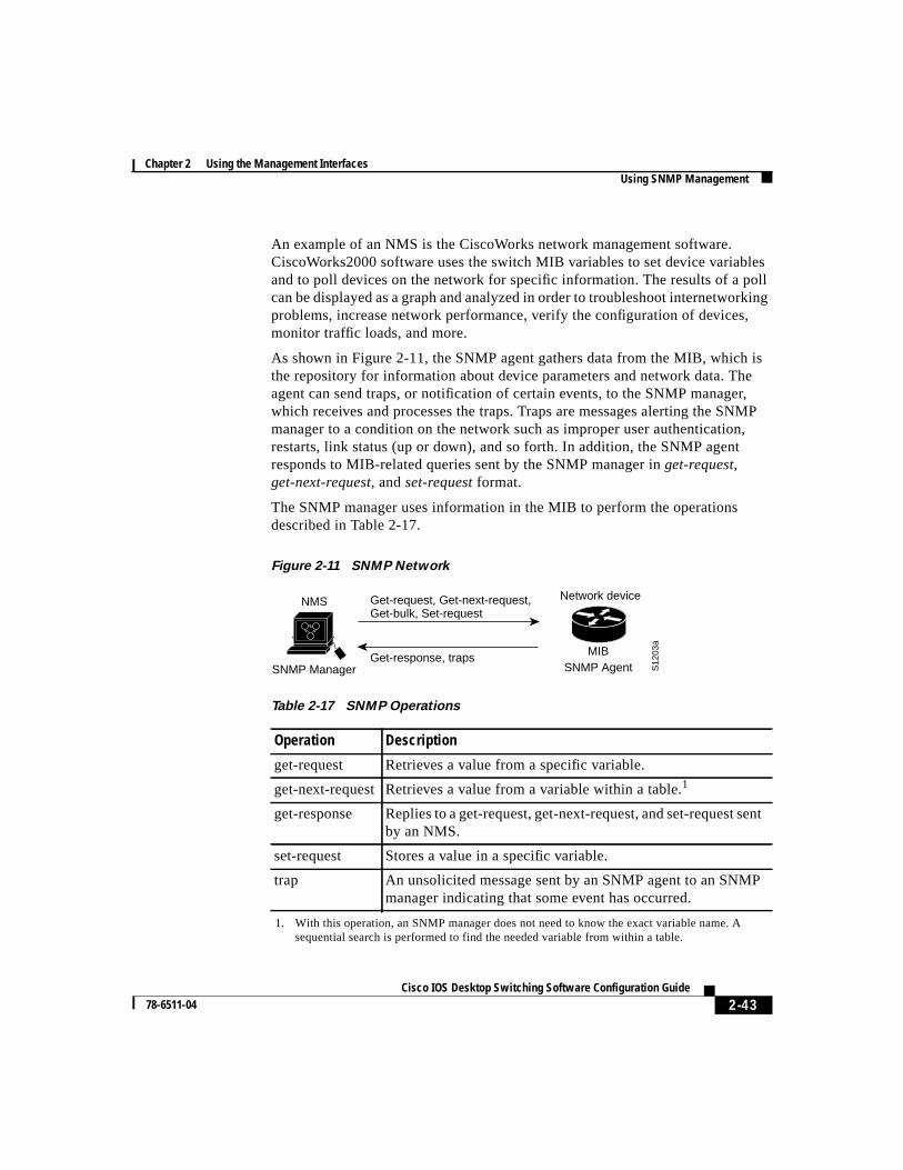
As shown in Figure 2-11, the SNMP agent gathers data from the MIB, which isthe repository for information about device parameters and network data. Theagent can send traps, or notification of certain events, to the SNMP manager,which receives and processes the traps. Traps are messages alerting the SNMPmanager to a condition on the network such as improper user authentication,restarts, link status (up or down), and so forth. In addition, the SNMP agentresponds to MIB-related queries sent by the SNMP manager inget-request,get-next-request, andset-request format.
The SNMP manager uses information in the MIB to perform the operationsdescribed in Table 2-17.
Figure 2-11 SNMP Network
Table 2-17 SNMP Operations
Operation Description
get-request Retrieves a value from a specific variable.
get-next-request Retrieves a value from a variable within a table.1
1. With this operation, an SNMP manager does not need to know the exact variable name. Asequential search is performed to find the needed variable from within a table.
get-response Replies to a get-request, get-next-request, and set-request sentby an NMS.
set-request Stores a value in a specific variable.
trap An unsolicited message sent by an SNMP agent to an SNMPmanager indicating that some event has occurred.
Get-request, Get-next-request,Get-bulk, Set-request
Network device
Get-response, traps S
1203
a
SNMP Manager
NMS
MIBSNMP Agent

Chapter 2 Using the Management InterfacesUsing SNMP Management
2-44Cisco IOS Desktop Switching Software Configuration Guide
78-6511-04
Managing Cluster Switches Through SNMPSNMP must be enabled for the Cluster Management reporting and graphingfeatures to function properly. When you power-up your 2900 or 3500 XL switchfor the first time, SNMP is enabled if you enter the IP information by using thesetup program and accept its proposed configuration. If you did not use the setupprogram to enter the IP information and SNMP was not enabled, you can enableit on the SNMP Configuration page described in the “Configuring SNMP” sectionon page 4-34. On Catalyst 1900 and 2820 switches, SNMP is enabled by default.
When a cluster is created, the command switch manages the exchange ofmessages between member switches and an SNMP application. The ClusterManagement software appends the member switch number (@esN, whereN is theswitch number) to the first configured RW and RO community strings on thecommand switch and propagates them to the member switch. The commandswitch uses this community string to control the forwarding of gets, sets, andget-next messages between the SNMP management station and the memberswitches.
Note When the a standby group is configured, the command switch canchange without the user’s knowledge. Use the first read-write andread-only community strings to communicate with the commandswitch if there is a standby group configured for the cluster.
If the member switch does not have an IP address, the command switch passestraps from the member switch to the management station, as shown inFigure 2-12. If a member switch has its own IP address and community strings,they can be used in addition to the access provided by the command switch. Formore information, see the “Changes to the SNMP Community Strings” section onpage 3-10 and the “Configuring SNMP” section on page 4-34.

2-45 Cisco IOS Desktop Switching Software Configuration Guide
78-6511-04
Chapter 2 Using the Management InterfacesUsing SNMP Management
Figure 2-12 SNMP Management for a Cluster
RMON SupportThis IOS software release supports four Remote Monitoring (RMON 1) groups.You can configure these groups by using an SNMP application or by using theCLI. The four supported groups are alarms, events, history, and statistics.
Trap
Trap
Trap
Command switch
Trap 1, trap 2, trap 3
Member 1 Member 2 Member 3
3302
0
SNMP Manager

Chapter 2 Using the Management InterfacesUsing SNMP Management
2-46Cisco IOS Desktop Switching Software Configuration Guide
78-6511-04