Embed Size (px)
Citation preview

180 TRANSPORTATION RESEARCH RECORD 1311
Using Strip Films To Record Pavement Distress in the Strategic Highway Research Program: Long-Term Pavement Performance Study
HERNAN DE SOLMINIHAC AND HARVEY ROPER
The system recommended by the researchers to the Long-Term Pavement Performance (LTPP) studies of the Strategic Highway Research Program for the collection and storage of surface distress data is described. Specifically, the distress acquisition system, film interpretation system, quality assurance plan, certification procedure for Pavement Distress Analysis System operators, and, finally, how the system benefits the L TPP study are described. There are several advantages to using this system: it is semiautomatic and provides a permanent record of the pavement surface; in addition, work is performed exclusively at night, ensuring that there will be a minimum of traffic interference. Films provide additional information for the LTPP studies; that is, a complete picture of each site is available at the office. Such a capability allows the engineers not only to analyze pavement distress, but to perform quality control of the test sites as well (e.g., inspecting the locations of the weigh-in-motion and automatic vehicle counters sites). In addition, this information can be used later to interpret the data analysis output. Although the system is limited in some respects, these limitations can be overcome through operator experience and use of supplemental information available from the site.
The Strategic Highway Research Program (SHRP) was initiated in 1987 in an attempt to stem the rapid deterioration of pavements nationwide. The Long-Term Pavement Performance (L TPP) studies, in turn, evolved out of SHRP as its primary pavement research program. In establishing the LTPP, researchers hoped to develop the tools needed to increase pavement performance and service life. The specific objectives of L TPP included
• Evaluation of existing design methods; • Development of improved strategies and design proce
dures for rehabilitation of existing pavements; • Development of improved design equations for new and
reconstructed pavements; • Determination of the effects of loading, environment,
material properties and variability, construction quality, and maintenance levels on pavement distress and performance; and
• Establishment of an international long-term pavement database to support current and future needs.
H. de Solminihac, Center for Trnnsportation Research, University of Texas at Austin, Austin, Tex. 78712. H. Roper, Texas Research and Development Foundation, 2602 Dellana Lane, Austin, Tex. 78746.
Two sets of pavement are currently under investigation by the L TPP program. The first set consists of nearly 800 existing pavement sections to be evaluated for the General Pavement Studies (GPS); the second set, the Specific Pavement Studies (SPS), will provide comparisons that isolate the effects of certain factors .
Data will be collected from these experimental sites for 20 years. The data collected through these studies will make up the National Pavement Performance Database (NPPDB), to be located at TRB. The data for each section will be grouped within seven modules: (a) environmental; (b) inventory; (c) laboratory materials testing; (d) maintenance; (e) monitoring of deflection, surface distress, profile, rut depth, and skid resistance; (f) traffic; and (g) rehabilitation. Periodically, the data collected will be analyzed to ensure that the goals of the L TPP studies are realized. The first strategic analysis of the data contained in the NPPDB is the objective of the contract on data analysis (J).
Although almost all of the SHRP-LTPP research undertaken to date has been directed toward the creation of the NPPDB, this data base is only meant to satisfy the LTPP design-related objectives. The end products of the data analysis contract will be the first that are aimed specifically at the major objectives cited, and the first that will employ the NPPDB for its intended purpose. The main tasks of the research will include (a) sensitivity analysis of explanatory variables in the NPPDB, (b) calibration of the AASHTO design equations, (c) development of pavement rehabilitation strategies, and (d) development of future T.TPP data analysis plans.
An important area within the NPPDB is the information relating to surface distress. To collect this information, SHRP uses a pavement distress data acquisition system developed by PASCO USA, Inc. This system had several advantages: it is highly automatic and is capable of producing a permanent record of the pavement surface (including rut depth information); in addition, because it is exclusively for night operation (working at a speed of 50 mph), traffic interference is kept to a minimum.
The main objective is to present the main components of the PASCO USA data acquisition system recommended by the researchers to SHRP for their collection and storage of distress data. Specifically, the distress acquisition system, film interpretation system, certification procedures for the interpretation system operators, and, finally, the important advantages-and limitations-of the system, are described.
de Solminihac and Roper
DESCRIPTION OF THE DISTRESS ACQUISITION SYSTEM (2)
Distress Acquisition System Vehicle
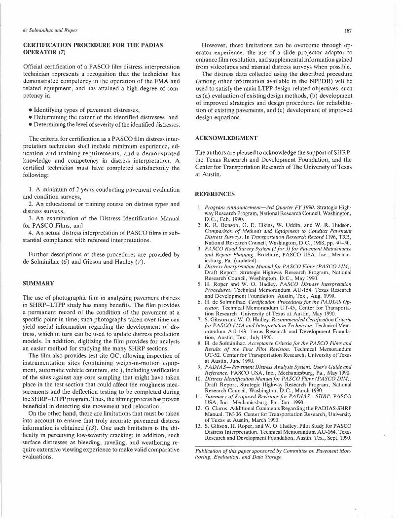
The distress acquisition system vehicle-properly termed the Roadrecon pavement photographing system vehicle-was developed by PASCO Corporation of Japan in 1970 (see Figure 1). While traveling at speeds of 5 to 55 mph, this van (weighing nearly 5 tons and running on diesel fuel) takes continuous photographs for distress information, and pulsed photographs for rut depth surveys. Two components of the system-the RR-70 and RR- 75 subsystems-perform these photographic functions.
Roadrecon-70 (RR-70)
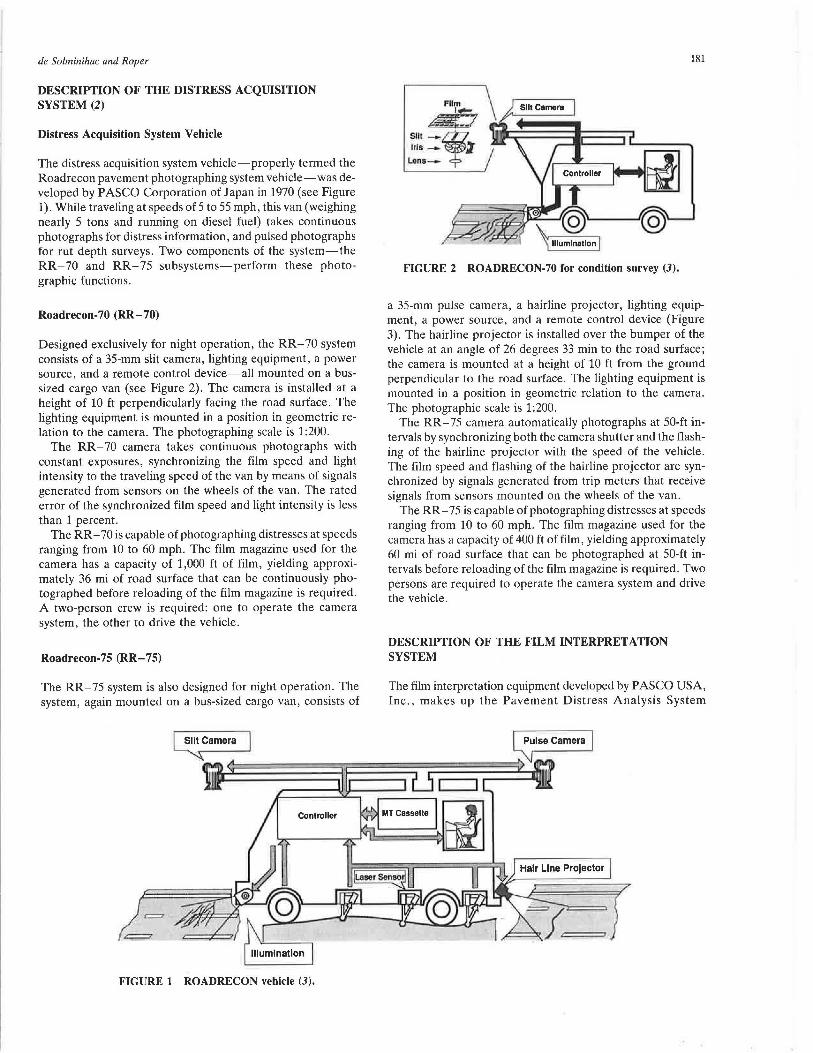
Designed exclusively for night operation, the RR-70 system consists of a 35-mm slit camera, lighting equipment, a power source, and a remote control device-all mounted on a bussized cargo van (see Figure 2). The camera is installed at a height of 10 ft perpendicularly facing the road surface. The lighting equipment is mounted in a position in geometric relation to the camera. The photographing scale is 1:200.
The RR-70 camera takes continuous photographs with constant exposures, synchronizing the film speed and light intensity to the traveling speed of the van by means of signals generated from sensors on the wheels of the van. The rated error of the synchronized film speed and light intensity is less than 1 percent.
The RR-70 is capable of photographing distresses at speeds ranging from 10 to 60 mph. The film magazine used for the camera has a capacity of 1,000 ft of film, yielding approximately 36 mi of road surface that can be continuously photographed before reloading of the film magazine is required. A two-person crew is required: one to operate the camera system, the other to drive the vehicle.
Roadrecon-7 5 (RR-7 5)
The RR-75 system is also designed for night operation. The system, again mounted on a bus-sized cargo van, consists of
·= =
FIGURE 1 ROADRECON vehicle (3).
181
s111-, Iris - ~
Lons-
,'------@)
FIGURE 2 ROADRECON-70 for condition survey (3).
a 35-mm pulse camera, a hairline projector, lighting equipment, a power source, and a remote control device (Figure 3). The hairline projector is installed over the bumper of the vehicle at an angle of 26 degrees 33 min to the road surface; the camera is mounted at a height of 10 ft from the ground perpendicular to the road surface. The lighting equipment is mounted in a position in geometric relation to the camera. The photographic scale is 1:200.
The RR- 75 camera automatically photographs at 50-ft intervals by synchronizing both the camera shutter and the flashing of the hairline projector with the speed of the vehicle. The film speed and flashing of the hairline projector are synchronized by signals generated from trip meters that receive signals from sensors mounted on the wheels of the van.
The RR-75 is capable of photographing distresses at speeds ranging from 10 to 60 mph. The film magazine used for the camera has a capacity of 400 ft of film, yielding approximately 60 mi of road surface that can be photographed at 50-ft intervals before reloading of the film magazine is required. Two persons are required to operate the camera system and drive the vehicle.
DESCRIPTION OF THE FILM INTERPRETATION SYSTEM
The film interpretation equipment developed by PASCO USA, Inc., makes up the Pavement Distress Analysis System

182
1,___-1.@ Hair Line Projector
FIGURE 3 ROADRECON-75 for rutting survey (3).
(PADIAS). The PADIAS, shown in Figure 4, is a set of applications designed to control the interpretation of pavement distresses from a 35-mm strip of film. The hardware consists of an IBM-compatible 386 computer, a film motion analyzer (FMA) for interpretation of 35-mm films, and a printer for preparing the reports.
A flow diagram of the distress interpretation procedure is shown in Figure 5 (5) . After receipt of the film from PASCO, the PASCO operator will complete a film quality review of the film to establish whether or not the film processing is satisfactory. During this acceptance review, the PAD IAS operator will observe the general condition (severity of distress or rutting) of the section on the basis of the distress and rut depth films. After completion of the film review, the operator will then complete the corresponding film logs. Any irregularities in the pavement test sections noted during the review of the film will be brought to the attention of administrative personnel for resolution. The film logs are then forwarded to SHRP and the four SHRP regional engineers.
After the film acceptance review is completed, the distress interpretation process can begin . A nomination data base is queried for the section under active distress interpretation to provide pertinent information on pavement type, lane width, underlying layers, etc. The GPS section site verification videos and PASCO USA rut depth films are reviewed, as needed, to enhance the interpretive process. On completion of the interpretation process, the operator then generates reports summarizing the distresses found in the section. These reports are then forwarded to the initial PADIAS quality control review team for needed quality control checks of the interpretation. The selection procedure for these initial checks will be based on PADIAS operator comments concerning difficulty in interpretation , distress report complexity or anomalies, film condition , and clarity. Aside from those sections selected for initial checks, a minimum of 10 percent of the interpreted film (or 1 in 10) should be reviewed by the quality control (QC) review team using a random selection procedure. If any discrepancies are noted by the quality control team, the section shall be re-reviewed by the principal PAD IAS operator to resolve such discrepancies in interpretation. If there are significant discrepancies observed in the random reviews or subsequent mandated review, then an increasingly higher percentage of the interpretation film (e.g., 20 or 30) should be reviewed by the initial PADIAS quality control review team.
After the quality control review has been completed, the processed data are then forwarded to the Regional Coordi-
TRANSPORTATION RESEARCH RECORD 1311
•• D D I D 11111111 F93 .11
FILM MOTION ANALYZER (FMA) IBM-COMPATIBLE 386 COMPUTER
FIGURE 4 Main components of PADIAS (4).
nation Office Contractor (RCOC). The RCOCs will then implement their own quality control review of the film and distress reports. If any discrepancies are noted, the RCOC and PADIAS teams will review the section and mutually resolve any discrepancies. When this regional quality control review process is completed, the distress data can then be entered in the Regional Information Management System (RIMS) .
Steps Before Film Interpretation (4)
The following four steps must be completed before the film interpretation can begin:
Step 1-0perator Certification. For reliable results , the P ADIAS operator must be certified to interpret PASCO films, according to criteria provided by de Solminihac (6) and Gibson and Hadley (7) .
Step 2-Film Acceptance. Once the film processing for each state is completed, PASCO forwards the film of all sites within that state. The PADIAS operator reviews the distress and rut depth film to establish the quality of the film as outlined by Roper and Hadley (5) and de Solminihac (8) .
Step 3-Equipment Calibration. If the equipment has been moved or if 6 months have passed since the last calibration, then a new calibration should be performed. The equipment calibration includes two activities: mirror alignment and FMA calibration (9).
Step 4-Film Threading. The film should be threaded into the FMA projector (8) .
Description of the Software Used for Film Interpretation (9)
The PADIAS distress interpretation program's main function is to interpret and record pavement distresses within a test section from the 35-mm RR-70 film using the FMA. This is accomplished by displaying the road surface one frame at a time, and using the FMA screen pointer (cursor) to designate and record distresses, and then to proceed to the next film frame . A frame is a 12- by 12-ft area , and normally a 500-ft section has 41 frames. Within the program there are three main menus to perform the needed functions . These include the entry menu (used for entering distresses), the edit menu (used for reviewing and changing existing distresses), and the

de Solminihac and Roper
Note GPS Irregularities mid Coordinate with
P-001 Pers0JU1el
Receive Diltrea1 Film
Review Film Quality
Fill Out Film Logs
Send Film Logs to SHRP llJld Regional
Engineer
Nomination Videotape 1111d Rui D film
Generate Nomination DataBueR
Enter Distress Data In RlMS
Note General Condition of
Section
Distress Intmpretation Proccu
O.....ate Re ru
Yes
Send Data to RCOC's
RCOC Quality Control Review
Yes
FIGURE 5 Distress interpretation procedure (5).
frame control menu (used for frame advancing, reversing, and other miscellaneous functions). The program will format the monitor into the following five areas (Figure 6):
1. Header information from the control section (top), 2. Grid cell area (middle left), 3. Work area (middle right), 4. Status line (second window from bottom), and 5. Bar menu line (bottom window).
Film Interpretation
Figure 7 shows a flow chart illustrating the film interpretation procedure. After the header file is completed, the DISTRESS INTERPRET function is selected from the system menu. However, before the actual interpretation is started, the road width must be defined by answering two program questions, indicating in the FMA (using the mouse) the lower left and the upper right portion of the displayed road surface. After this alignment is defined, the starting point must be indicated. This starting point corresponds to the starting mark of the LTPP section (9).
Then the actual film interpretation can begin. For this activity, the operator may use the Distress Identification Manual
AREA I : HEADER INFORMATION
AREA2: AREA3:
GRID CELL AREA WORK AREA
AREA 4 : STATUS LINE
AREA 5 : BAR MENU LINE
FIGURE 6 The five main working areas of the monitor displayed when the distress interpret option is selected (4).
183

184
i=l+1
START
FILM TI-IREADING
HEADER
SElECT "DISTRESS INTERPRET" OR <F10>
DEFINE STARTING POINT
SELECT DISTRESS "I" OF FRAME ··
TRANSPORTATION RESEARCH RECORD 1311
j = j + 1
DO THE ALIGNMENT
DEFINE STOPPING PO!NT
ourr
FIGURE 7 Flow chart for the film interpretation process (4).
(10). A screen, such as the one shown in Figure 8, will appear. Starting with the first frame, the first distress identified in that frame is selected and assigned a severity level (if applicable). The location of that distress is also recorded using the mouse and the grid; finally, the distress is saved using the SAVE command on the bar menu line. Then, using the same procedure described earlier, the next distress within the same frame is recorded.
When the first frame is completed, the second frame is selected; the process continues until all frames are completed. The distress data consist of three basic parts: (a) the distress type; (b) the severity level; and (c) the area location. The distress type identifies the distress on the basis of the pavement type and film interpretation. The distress menu for each pavement type appears in the work area when the cursor is moved to the right side of the screen when in the entry mode. The severity level is set by a message window in the work area after the distress is identified. A check box indicating either low, moderate, or high levels must be selected. If no severity level is necessary, the program will inform the user und request the pressing of a cursor button to continue. After that, the program will record the grid cell location of the
PADIAS DISTRESS INTERPRETATION SHRP HEADER DATA PADIAS2 1.1 Control Sec NR LTPP Sec N' Oa.to Tlme Sp-i PASCO U~a\w.'a
Operator Name Weather Cond. Curr. Frame Feet
PAVEMENT TYPE i Olstraaa 1 for pav type I Dlatre99 2 tor pav type I Distress 3 1or pav type I
Dlstreso n tor pav type I
erase pavement type dlatre11 datlnlllon aavarlty I I distress Indio. (AC,JCP ,CRCP) (grid cell or levels
mode or frame
2 pt. line)
ENTRY MENU CONTROL: Erase, Reset, Sava, Review, Next 1rm, Frm ctl, Quit EDIT MENU CONTROL: Erase, Reset, Add, Change, Delete, Next, Next Frame, FrmCtl, Quit FRAME CONTROL MENU: Align, Advance, Reverse, Reset, Restart, Start pt, Stop pl, Escape
FIGURE 8 Screen sketch of the l'AUIAS distress interpretation program (4).

de Solminihac and Roper
distress by positioning the cursor over the film where the distress occurs. The distress is represented on the grid area on the monitor by the blackened grid cells (9).
Before quitting the program, the stopping point should be defined in the frame control menu using the STOP PT command. This point is used to define the end of the LTPP sections being studied. To finish the interpretation process, the QUIT command in the entry menu control is used.
Checking Consistency (5,11,12)
Immediately after completing a distress interpretation for a test section, the operator will run a consistency check using the PADIAS consistency checking program from the main PADIAS menu to ensure that each 1- by 1-ft grid square presents only those distresses that could, in practice, coexist for the type of pavement structure being analyzed. If the PADIAS operator encounters a condition that appears to be an exception to a coexistence matrix, such as the one shown in Figure 9, it should be noted on the interpretation log form for possible review by the QC team and brought to the attention of a pavement engineer.
Output of the PADIAS (5)
The output of the PADIAS consists of a series of (a) printouts that summarize and graphically display the section condition, and (b) software files that subsequently are used to transfer the section distress interpretation information to the information management system (IMS). The control section report program from the main menu produces this output.
The reporting output for a section is available in the following four distinct formats:
1. The section map report option produces a graphic representation of each frame of film for an entire test section in
1. Allioator (Fati•ue) Crackin•
2. Block Crackin•
3. Edlle Crackimz
4_ Lon•;tlldinal Ctackin•
5. Reflection Crackin• at Joints
6. Transverse Cra.ckinP'.
?. Patch/Patch Deterjoration
8. Potholes
9. Ruttin2
10. Sbovjn2
IL Bleed in•
12. Poli•hc<S A•orcuto
13. R1ivcHne md Waatherin1t
14. Lane-lo-Shoulder Dronoff
15. Water Bleedin• & Pwnrnn•
15A. Lane-to-Shoulder Seoeration
Legend N = Cannot coexist
C = Can coexist
• = Not applicable
I 2 3 4
N N c c c
N
5
N
c N
c
185
which a distress was recorded. The location of each distress is indicated using a letter or number code. Because one page per frame is required, a complete section frame map printout can include as many as 42 pages and require as much as 30 min of printing time for the existing equipment and set-up defaults.
2. The grid summary report is a one-page summary of the distresses in a section and indicates the total number of grid cells affected by a particular distress at each severity level.
3. The section summary report (Figure 10) is a one-page summary of the distresses in a section listed by type and severity level in units appropriate to the type of distress. This report corresponds to the input for the LTPP-IMS.
4. The frame map report provides the operator with the option of calling up and generating a printout of a particular frame within a section.
These four reports can be provided in two types of output: a visual copy (on the screen) or a hard copy (printout). To output to the screen, the View Report function is selected, whereas the Print Report function is selected to provide a hard-copy output print.
After the distress interpretation of a test section is completed, the PADIAS operator should print out a grid cell summary report and a section summary report. These reports should be compiled with the nomination data base information and the interpretation log form for the section and submitted to the senior pavement engineer for review. This packet should provide sufficient information about both the condition of a pavement section and the film interpretation on which to base acceptance or QC review decisions.
A printout of the section map report for a section should only be made (a) when the data are going to be compared with existing manual survey results, or (b) when needed in the field for an on-site comparison. Printing out a section map for each section would be time consuming and would require large amounts of paper.
6 7 8 9 10 11 12 13 14 15 !SA
c c N • N N . c • . . c N N • N N • c . . • c c N • c N • c . . • c c N . N N . c . . . c c N • c c • c . . .
c N • c c • c • • • N • c c • c . . •
• N N • N • • • c c . c . . •
c . N • • . • N • . . . . . . . . •
• • •
FIGURE 9 Consistency checking matrix for asphalt concrete pavements (11,12).

186
Control Section ID LTPP GPS Section ID DatQ or Filming 11meof l'ilming Filming Operator Weather Condition Measuring Speed Pavement Width Date of Analysis Time of Analysis Analysis Operator
287012 287012 5(27/89 10:42 unit# 1 unknown 20 m.p.h. 500 feet 7/18f)O 10:30 sdg
Exi•ting AC Overlay of JCP
Distress Type Number of Marked Grid Meshes
---------~ igb_.McdlllllL___l.ow __ _
Alligator (Fatigue) Cracking
Block Cracking
Edge Cracking
Longitudinal Cracking
Long. Reflect. Cracking at Jts
Truns. Reflect. Cracking at Jts
Transverse Cracking
Patch/Patch Deterioration
Potholes
Shoving
Bleeding
Raveling and Weathering
Lane-to-Shoulder Separation
Water Bleeding and Pumping
0
38
0
FIGURE 10 Section summary report.
Quality Control Review (5)
64
145
0
20
23
20
After interpretation, the section summary reports are printed and attached to the nomination data base project information sheet and the film reviewer's interpretation log. The reports are then presented to the distress quality control review team. The quality control team reviews the reports and selects those requiring review on the basis of PADIAS operator comments, film condition and clarity, pavement type, and requirements for random quality control checks. In this QC review, the slide projector adapter is used to view the PASCO distress and rut depth films (7). The section's nomination videotape may be reviewed to confirm the PADIAS operator's interpretation of the section. If discrepancies exist, the differences are listed, the PADIAS operator will reinterpret the section, and a mutual resolution of the discrepancies will be made final.
RCOC Quality Control Review (5)
Upon satisfactory completion of the PAD IAS distress quality control team review, the distress data are forwarded to the appropriate RCOC. The RCOC distress quality control (QC) team reviews the reports and uses a combination of the slide projector view of the PASCO film (8), the nomination verification videotape, and spot checking of the actual section conditions in the field to confirm the P ADIAS operator's interpretation of the section. If discrepancies exist, the differences are listed and communicated to the P ADIAS con-
TRANSPORTATION RESEARCH RECORD 1311
tractor so that the P ADIAS operator can review the section and conduct a reinterpretation to resolve the discrepancies.
The RCOCs will likely develop review criteria on the basis of information available in the PAD IAS output packet (which includes a grid cell summary report, section summary report, nomination data base information, and interpretation log) correlated with results of an early concentrated QC and quality assurance effort in review of the P ADIAS FMA distress interpretation.
As an aid in the early QC effort, it is recommended that the RCOCs undertake a full (Level I) review of all frames of at least 10 of the first 20 FMA interpreted films and a partial review (i.e., 5 to 10 frames) of the remaining 10 designated interpreted films. The films for full review should be based on a random selection method, whereas the frames to be investigated in the partial review group should also be randomly selected.
If discrepancies are encountered in the partial reviews of the second set of 10 L TPP sections, then a full review of all 10 of these sections should be undertaken. In addition, any significant discrepancies in the full review of the first set of 10 L TPP sections or the mandated subsequent full review of the second set of L TPP sections should result in the continuation of the initial review procedure of the PASCO film for the next (randomly selected) 20 L TPP sections. This process should be continued until results from distress interpretation by PADIAS FMA and RCOCs are consistent and free of discrepancies.
On the other hand, if no significant discrepancies in interpretation are encountered in either the full or partial Level I review, then the RCOCs could opt to undertake subsequent reviews at a reduced rate (Level II). For example, the subsequent review process could consist of one out of four randomly selected sites scheduled for full-frame review, whereas the remaining sites (three out of four) could be partially reviewed.
If, at any subsequent time in the Level II review process, a new P ADIAS FMA operator is introduced or significant discrepancies are encountered, then the initial review format could be reinstated and maintained until a desirable level of consistency is obtained between P ADIAS FMA and RCOC distress interpretations. In this instance, those sets of interpretations involving partial reviews of three out of four sites should be rescheduled for review under the initial review format (i.e., Level I).
The RCOC QC interpretation team should document the discrepancies encountered and notify the P ADIAS FMA of a need for re-review of a particular section. The films for L TPP sections that have been reviewed a second time by a P ADIAS FMA operator should subsequently be fully reviewed by the RCOCs.
Randomization in the selection of the highway sections is essential; however, the review process may require adjustments to ensure a minimum number of full reviews for all pavement types (i.e., asphalt concrete, joint reinforced pavement, continuous reinforced concrete pavement, and jointed pavement).
Entry of Data into RIMS
On satisfactory completion of the RCOC distress QC team review, the distress data are entered in the RIMS data base.
de So/minihac and Roper
CERTIFICATION PROCEDURE FOR THE PADIAS OPERATOR(7)
Official certification of a PASCO film distress interpretation technician represents a recognition that the technician has demonstrated competency in the operation of the FMA and related equipment, and has attained a high degree of competency in
• Identifying types of pavement distresses, • Determining the extent of the identified distresses, and • Determining the level of severity of the identified distresses.
The criteria for certification as a PASCO film distress interpretation technician shall include minimum experience, education and training requirements, and a demonstrated knowledge and competency in distress interpretation. A certified technician must have completed satisfactorily the following:
1. A minimum of 2 years conducting pavement evaluation and condition surveys,
2. An educational or training course on distress types and distress surveys,
3. An examination of the Distress Identification Manual for PASCO Films, and
4. An actual distress interpretation of PASCO films in substantial compliance with refereed interpretations.
Further descriptions of these procedures are provided by de Solminihac (6) and Gibson and Hadley (7).
SUMMARY
The use of photographic film in analyzing pavement distress in SHRP-LTPP study has many benefits. The film provides a permanent record of the condition of the pavement at a specific point in time; such photographs taken over time can yield useful information regarding the development of distress, which in turn can be used to update distress prediction models. In addition, digitizing the film provides for analysts an easier method for studying the many SHRP sections.
The film also provides test site QC, allowing inspection of instrumentation sites (containing weigh-in-motion equipment, automatic vehicle counters, etc.), including verification of the sites against any core sampling that might have taken place in the test section that could affect the roughness measurements and the deflection testing to be completed during the SHRP-LTPP program. Thus, the filming process has proven beneficial in detecting site movement and relocation.
On the other hand, there are limitations that must be taken into account to ensure that truly accurate pavement distress information is obtained (13). One such limitation is the difficulty in perceiving low-severity cracking; in addition, such surface distresses as bleeding, raveling, and weathering require extensive viewing experience to make valid comparative evaluations.
187
However, these limitations can be overcome through operator experience, the use of a slide projector adaptor to enhance film resolution, and supplemental information gained from videotapes and manual distress surveys when possible.
The distress data collected using the described procedure (among other information available in the NPPDB) will be used to satisfy the main LTPP design-related objectives, such as (a) evaluation of existing design methods, (b) development of improved strategies and design procedures for rehabilitation of existing pavements, and (c) development of improved design equations.
ACKNOWLEDGMENT
The authors are pleased to acknowledge the support of SHRP, the Texas Research and Development Foundation, and the Center for Transportation Research of The University of Texas at Austin.
REFERENCES
1. Program Announcement-3rd Quarter FY 1990. Strategic Highway Research Program, National Research Council, Washington, D.C., Feb. 1990.
2. K. R. Benson, G. E. Elkins, W. Uddin, and W. R. Hudson. Comparison of Methods and Equipment to Conduct Pavement Distress Surveys. In Transportation Research Record 1196, TRB, National Research Council, Washington, D.C., 1988, pp. 40-50.
3. PASCO Road Survey System (1for3) for Pavement Maintenance and Repair Planning. Brochure, PASCO USA, Inc., Mechanicsburg, Pa. (undated).
4. Distress Interpretation Manual for PASCO Films (PASCO F/M). Draft Report, Strategic Highway Research Program, National Research Council, Washington, D .C., May 1990.
5. H. Roper and W. 0. Hadley. PASCO Distress Interpretation Procedures. Technical Memorandum AU-154. Texas Research and Development Foundation, Austin, Tex., Aug. 1990.
6. H . de Solminihac. Certification Procedures for the PAD/AS Operator. Technical Memorandum UT-45, Center for Transportation Research, University of Texas at Austin, May 1990.
7. S. Gibson and W. 0. Hadley. Recommended Certification Criteria for PASCO FMA and Interpretation Technician. Technical Memorandum AU-149. Texas Research and Development Foundation, Austin, Tex., July 1990.
8. H. de Solminihac. Acceptance Criteria for the PASCO Films and Results of the First Film Revision. Technical Memorandum UT-52. Center for Transportation Research, University of Texas at Austin , June 1990.
9. PAD/AS-Pavement Distress Analysis System. User's Guide and Reference. PASCO USA, Inc., Mechanicsburg, Pa., May 1990.
10. Distress Identification Manual for PASCO Films (PASCO DIM). Draft Report, Strategic Highway Research Program, National Research Council, Washington, D.C., March 1990.
11. Summary of Proposed Revisions for PADIAS-SHRP. PASCO USA, Inc., Mechanicsburg, Pa., Jan. 1990.
12. G. Claros. Additional Comments Regarding the PADIAS-SHRP Manual. TM-36. Center for Transportation Research, University of Texas at Austin, March 1990.
13. S. Gibson, H. Roper, and W. 0. Hadley. Pilot Study for PASCO Distress Interpretation. Technical Memorandum AU-164. Texas Research and Development Foundation, Austin, Tex., Sept. 1990.
Publication of this paper sponsored by Committee on Pavement Monitoring, Evaluation, and Data Storage.