Embed Size (px)
Citation preview
Research ArticleUsing Simplified Models to Assist Fault Detection and Diagnosisin Large Hydrogenerators
Geraldo Carvalho Brito Junior12 Roberto Dalledone Machado2 and Anselmo Chaves Neto2
1Center for Engineering and Exact Sciences Western Parana State University (UNIOESTE) Foz do Iguacu PR Brazil2Numerical Methods for Engineering Graduate Program Federal University of Parana (UFPR) Curitiba PR Brazil
Correspondence should be addressed to Geraldo Carvalho Brito Junior gcbritojrgmailcom
Received 8 December 2016 Revised 25 February 2017 Accepted 6 March 2017 Published 27 April 2017
Academic Editor Dong Wang
Copyright copy 2017 Geraldo Carvalho Brito Junior et al This is an open access article distributed under the Creative CommonsAttribution License which permits unrestricted use distribution and reproduction in any medium provided the original work isproperly cited
Based on experimental evidence collected in a set of twenty 700MW hydrogenerators this article shows that the operatingconditions of large hydrogenerators journal bearings may have unpredictable and significant changes without apparent reasonsThese changes prevent the accurate determination of bearing dynamic coefficients and make the prediction of these machinesdynamic behavior unfeasible even using refined models This makes it difficult to differentiate the normal changes inhydrogenerators dynamics from the changes created by a fault event To overcome such difficulty this article proposes a back-to-basics step the using of simplified mathematical models to assist hydrogenerators vibration monitoring and exemplifies thisproposal by modeling a 700MW hydrogenerator A first model estimates the influence of changes in bearing operating conditionsin the bearing stiffnesses considering only the hydrodynamic effects of an isoviscous oil film with linear thickness distribution Asecond model simulates hydrogenerators dynamics using only 10 degrees of freedom giving the monitored vibrations as outputsunder normal operating conditions or in the presence of a fault This article shows that simplified models may give satisfactoryresults when bearing operating conditions are properly determined results comparable to those obtained by more refined modelsor by measurements in the modeled hydrogenerator
1 Introduction
Due to the strategic importance of large hydrogenerators(LHG) and due to the potential risk of catastrophic failures[1] the application of vibration-based condition monitoringto thesemachines is a real necessity LHG are vertical rotatingmachines with a complex vibratory behavior [2] As will beexemplified in the following sections the operating and theboundary conditions of LHG journal bearings may experi-ence unpredictable and significant changes without apparentreasons Due to this the bearing dynamic coefficients cannotbe determined with an adequate accuracy even by the mostsophisticated mathematical models Also as a consequencethe dynamic behavior of LHG may have similar erratic andsubstantial changes preventing satisfactory theoretical pre-dictions even when using refined models This complicatesfault detection and fault diagnosis using pattern recognitionapproach [3 4] as it is difficult to differentiate the normal
and typical changes in the dynamic behavior of thesemachines from those changes originated by the advent of afault Moreover several faults that frequently happen in LHGbegin in the journal bearings or have strong influences intheir dynamic coefficients [2 5] Therefore the understand-ing of journal bearing dynamics has a central importance infault detection and fault diagnosis in LHG
Considering this situation this article proposes a back-to-basics step the using of simplifiedmathematical models toassist fault detection and fault diagnosis in LHG It illustratesthis proposal by modeling a 700MW hydrogenerator withdifferent purposes Since it is easier to estimate and to mon-itor bearing stiffness than bearing damping and consideringalso that both parameters have similar sensitivity to faults [6]this article focuses on bearing stiffness A first model is usedto estimate the influence of changes in bearing operating con-ditions in the bearing stiffness considering only the hydrody-namic effects of an isoviscous oil film with a linear thickness
HindawiInternational Journal of Rotating MachineryVolume 2017 Article ID 9258456 18 pageshttpsdoiorg10115520179258456
2 International Journal of Rotating Machinery
distribution A secondmodel simulates the dynamic behaviorof LHGunder normal operating conditions or in the presenceof the more frequent faults taking into account gyroscopiceffects and bearing anisotropy but using a simplified RigidBody Model with only 10 degrees of freedom (DOF) Basedon the results of these applications this article shows thatthese simplified mathematical models give suitable resultswhen bearing conditions are properly determined resultscomparable to the those obtained using more advancedmathematicalmodels or to realmeasurements in themodeledhydrogenerators
Besides this introductory section this article is structuredas follows Section 2 presents some experimental results anda brief review of mathematical modeling applied to LHGwhich justify the using of simplifiedmodels to assist the appli-cation of vibration-based condition monitoring techniquesto these machines Section 3 describes the two formerlymentioned mathematical models including their validationSection 4 shows applications of these models under theseveral possible operating conditions of the journal bearingsand presents a discussion of the obtained results Section 5presents the concluding remarks of this article
2 Remarks on LHG Models
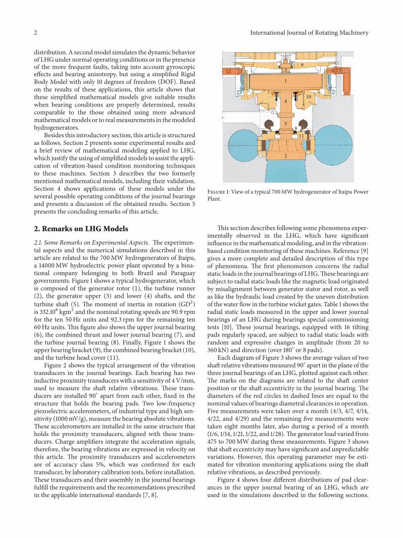
21 Some Remarks on Experimental Aspects The experimen-tal aspects and the numerical simulations described in thisarticle are related to the 700MW hydrogenerators of Itaipua 14000MW hydroelectric power plant operated by a bina-tional company belonging to both Brazil and Paraguaygovernments Figure 1 shows a typical hydrogenerator whichis composed of the generator rotor (1) the turbine runner(2) the generator upper (3) and lower (4) shafts and theturbine shaft (5) The moment of inertia in rotation (1198661198632)is 332106 kgm2 and the nominal rotating speeds are 909 rpmfor the ten 50Hz units and 923 rpm for the remaining ten60Hz units This figure also shows the upper journal bearing(6) the combined thrust and lower journal bearing (7) andthe turbine journal bearing (8) Finally Figure 1 shows theupper bearing bracket (9) the combined bearing bracket (10)and the turbine head cover (11)
Figure 2 shows the typical arrangement of the vibrationtransducers in the journal bearings Each bearing has twoinductive proximity transducers with a sensitivity of 4Vmmused to measure the shaft relative vibrations These trans-ducers are installed 90∘ apart from each other fixed in thestructure that holds the bearing pads Two low-frequencypiezoelectric accelerometers of industrial type and high sen-sitivity (1000mVg) measure the bearing absolute vibrationsThese accelerometers are installed in the same structure thatholds the proximity transducers aligned with these trans-ducers Charge amplifiers integrate the acceleration signalstherefore the bearing vibrations are expressed in velocity onthis article The proximity transducers and accelerometersare of accuracy class 5 which was confirmed for eachtransducer by laboratory calibration tests before installationThese transducers and their assembly in the journal bearingsfulfill the requirements and the recommendations prescribedin the applicable international standards [7 8]
1
4
5
3
2
9
10
13
118
7
612
Figure 1 View of a typical 700MWhydrogenerator of Itaipu PowerPlant
This section describes following some phenomena exper-imentally observed in the LHG which have significantinfluence in themathematicalmodeling and in the vibration-based conditionmonitoring of these machines Reference [9]gives a more complete and detailed description of this typeof phenomena The first phenomenon concerns the radialstatic loads in the journal bearings of LHGThese bearings aresubject to radial static loads like the magnetic load originatedby misalignment between generator stator and rotor as wellas like the hydraulic load created by the uneven distributionof the water flow in the turbine wicket gates Table 1 shows theradial static loads measured in the upper and lower journalbearings of an LHG during bearings special commissioningtests [10] These journal bearings equipped with 16 tiltingpads regularly spaced are subject to radial static loads withrandom and expressive changes in amplitude (from 20 to360 kN) and direction (over 180∘ or 8 pads)
Each diagram of Figure 3 shows the average values of twoshaft relative vibrationsmeasured 90∘ apart in the plane of thethree journal bearings of an LHG plotted against each otherThe marks on the diagrams are related to the shaft centerposition or the shaft eccentricity in the journal bearing Thediameters of the red circles in dashed lines are equal to thenominal values of bearings diametral clearances in operationFive measurements were taken over a month (43 47 414422 and 429) and the remaining five measurements weretaken eight months later also during a period of a month(16 114 121 122 and 128)The generator load varied from475 to 700MW during these measurements Figure 3 showsthat shaft eccentricity may have significant and unpredictablevariations However this operating parameter may be esti-mated for vibration monitoring applications using the shaftrelative vibrations as described previously
Figure 4 shows four different distributions of pad clear-ances in the upper journal bearing of an LHG which areused in the simulations described in the following sections
International Journal of Rotating Machinery 3
Accelerometer
Transducers support
Proximity transducer
Transducers
Transducers
Pad
Heat exchanger
1
2
3
45
6
7
8
6
5
412
11
109
13
14
1615 12
87
3
Y direction
X direction
Thrust block
Figure 2 Transducers arrangement in the lower journal bearing
Table 1 Radial static loads measured in the journal bearings of an LHG
Operating condition Upper bearing Lower bearingSpeed [rmin] Power [MW] Load [kN] Directed to Pad Load [kN] Directed to Pad785 0 31 13 21 7923 0 61 8 91 14923 600 248 15 295 7923 700 274 10 294 15923 700 316 16 355 9
The blue circle shows the bearing radial nominal clearance(200120583m) referred to as clearance condition A The greenclosed curve designates the clearances measured with thegenerator excited at 0MW during bearings special commis-sioning tests [10] nominated as condition BThe orange ellip-tical curve with crossed marks shows the clearances obtainedby simulation using commercial software based on the FiniteVolume Method (FVM) denoted as clearance condition CThe temperatures measured in the bearing bracket whenthe generator was operating at a steady-state condition withnominal load (700MW) were used as boundary conditionsin this simulation Finally the red outer curve defines theclearancesmeasured at 700MW also during the cited bearingspecial commissioning tests [10] referred to as conditionD The significant dimensional changes when the generator
is loaded are caused by the differential heating of bracketarms originated by the electromagnetic field induced by thegenerator terminals components (12) and (13) in Figure 1This effect may have significant consequences but usuallyis disregarded by the most refined bearing models It makesbearing anisotropic with clearances much larger than thenominal values decreasing the predicted bearing stiffnessexpressively [6] The distribution of the pads clearances ofa journal bearing may be evaluated using the pads temper-atures measured at steady-state condition [9]
22 Some Remarks on LHGModels Thedynamic behavior ofan LHG has a considerable dependence on the dynamic coef-ficients of journal bearings [11] For the sake of convenience
4 International Journal of Rotating Machinery
180 200 220 240
4347414422429
16114121122128
SH-UJB-X (mm)
SH-U
JB-Y
(mm
)
180
200
220
240
(a)
130
150
170
190
130 150 170 190
4347414422429
16114121122128
X (mm)
SH-L
JB-
SH-LJB-
Y(m
m)
(b)
200
220
240
260
200 220 240 260
4347414422429
16114121122128
X (mm)
Y(m
m)
SH-TJB-
SH-T
JB-
(c)
Figure 3 Shaft eccentricity in the upper (a) lower (b) and turbine (c) journal bearings of a 700MW hydrogenerator measured for severalmonths
200
400
600
800
30
210
60
240
90
270
120
300
150
330
180 0X
Y
Figure 4 Pads clearances distribution (120583m) in the upper journalbearing of an LHG (a) nominal clearance condition A blue circle(b) measured at 0MW condition B closed curve in green (c)simulated at 700MW condition C crossed ellipse in orange (d)measured at 700MW condition D outer closed curve in red
in some cases the dynamic coefficients are well-defined andfixed parameters [12 13] However it is well-known thatbearing operating conditions (radial static load viscosityor clearance) have significant influence in the dynamiccoefficients [6] As LHG are vertical rotating machines theradial static loads in the journal bearings are not prede-fined For this reason some references prescribe this loadunder different basis For instance in the dynamic analysis
of Itaipu hydrogenerators the manufacturer assumed thatthis load was 600 kN when the generator is excited [14]independently of the generator power (Table 1 indicates thatthis load increases with the generator power and reachesapproximately half of this value) Based on previous testsNasselqvist et al [15] considered that the radial static load inthe journal bearings of a 42MW hydrogenerator of verticalassembly was 30 kN
In other references the radial static load was measuredusing strain gauges installed in the bearing bracket arms[16] or in the pivot pins of the bearing pads [17] This loadmay be also estimated using curves relating radial load withshaft eccentricity calculated previously In this case the shafteccentricity was estimated using the shaft relative vibrationsignals acquired in bearing orthogonal directions The usingof four proximity transducers instead of the usual twotransducers arrangement similarly to the procedure used ingenerator air gapmonitoringmay improve thismeasurementaccuracy [18]
Cardinali et al [11] modeled a hydrogenerator in twodifferent ways The first way used a nonlinear model wherethe equation of motion was solved simultaneously with theReynolds equations of the journal bearings pads The secondway used a linear model where the journal bearing dynamiccoefficients were determined under the operating conditionsthat provide the highest coincidence between the character-istic frequencies of both linear and nonlinear models Xu etal [19] also used a nonlinear model reducing the processingtime by means of a database containing the journal bearingsforces calculated previously for the several possible operat-ing conditions
Tiwari et al [20] remark that ldquohistorically theoreticalestimation of the dynamic bearing characteristics has alwaysbeen a source of error in the prediction of rotor-bearingsystemsrdquo mainly due to the difficulty of determining bearingoperating conditions accurately Both bearing radial static
International Journal of Rotating Machinery 5
load and the resulting shaft eccentricity are used to charac-terize bearing operating conditions Even in the more refinedmodels once the shaft eccentricity is determined the padsclearances are calculated considering that the pivot point ofall pads lies in a perfect circle This means that the bearinghousing is ideal without the dimensional changes describedin the previous section (Nasselqvist et al [17] comment thatthe geometry of hydrogenerator bearing brackets ldquochangeswith temperature as the generator temperature varies frombetween 15 and 80∘Crdquo influencing ldquobearing clearances whichchanges the relation between bearing propertiesrdquo howeverapparently no further investigations were done in this direc-tion) Then bearing coefficients are determined consider-ing only the oil film hydrodynamic effects (hydrodynamicmodel) or considering the additional thermal effects frombearing losses (thermohydrodynamic or THD model) orwith the deformation effects created by the oil film pressure(thermoelastohydrodynamic or TEHDmodel) [21] Dimondet al [21] highlight the needs of using TEHD models totheoretically determine the dynamic coefficients remarkingthat even in this case the ldquoagreement between theory andexperiment for bearing coefficients is seldom better than10ndash20 percentrdquo
In most of the references the journal bearing dynamiccoefficients were obtained using Reynolds bearing modelsolving Reynolds equation by the Finite Difference Method(FDM) Nevertheless Xu et al [19] used the BentlyndashMuszynska bearing model [22] and Wang et al [23] solvedReynolds equation using an approximated analytical solutionthrough the Variable Separation Method LHG shafts aremodeled using Bernoulli beam element [11] or Timoshenkobeam element [19] The Finite Element Method (FEM) wasused in many of the recent articles while the Transfer MatrixMethod (TMM) is encountered in some older references[14 24] In most cases the generator rotor and the turbinerunner aremodeled as rigid discs [11 19] their radial and axialelasticity are only considered in some cases [14]The dynamiceffects of turbine labyrinth seals are also considered only ina few references [11] Some articles investigate the effects ofmagnetic pull in hydrogenerators dynamics [12] Howeverthe magnetic pull in itself is always modeled by a negativestiffness which is usually determined by the generator man-ufacturer and depends on empirical coefficients like the polefactor [25] This stiffness depends on mainly the magneticexcitation of the generator and should have no significantinfluence of the generator power
3 Simplified Models to Assist FaultDetection and Diagnosis
A mathematical model used to assist fault detection andfault diagnosis in a rotating machine usually requires lessrefinement than themodels used during the design phase Forinstance at the design phase the journal bearing model mustpredict adequately how bearing losses will influence oil filmviscosity However this viscositymay be easily estimated dur-ing operation using the monitored temperatures of bearingpads and lubricant
31 Mathematical Model to Theoretically EstimateBearing Stiffness
311 Model Description The frequent unpredictable andsignificant changes in the bearing operating conditions maymake the more refined models to determine bearing stiffnessuseless Anyway many times it is necessary to estimatebearing stiffness for a well-defined operating condition Theelementary hydrodynamic model presented in Figure 5 atilting pad journal bearing with plane surfaces may be usedin this case This model uses the rectangular coordinates 119909 inthe shaft sliding direction 119911 in the shaft axial direction and 119910across the oil film thickness Each bearing pad has length 120573119877andwidth 119871 and is supported by a pivot located at coordinates(120572119877 0 0)
The oil film thickness is given by 119910 = ℎ(119909) when shaftand bearing are aligned with thicknesses ℎin at leading edgeand ℎout at the trailing edge A given point of shaft surface hasvelocities 119906119886 V119886 and119908119886 respectively at 119909 119910 and 119911 directionsIn the same order a point of the pad surface has velocities 119906119887V119887 and119908119887 If pad velocities are negligible (119906119887 = 0 V119887 = 0 and119908119887 = 0) and if shaft surface velocity is negligible at 119911 direction(119908119886 = 0) the oil film pressure 119901 = 119901(119909 119911) may be obtainedby solving Reynolds equation which is given by [26]
120597120597119909 (ℎ3 120597119901120597119909) + 120597120597119911 (ℎ3 120597119901120597119911) = 6120578119880120597ℎ120597119909 (1)
where 119880 is the shaft tangential velocity and 120578 is the lubricantdynamic viscosity
It may be shown that the pad attitude (119899 = ℎinℎout) forthis bearing may be determined by the following equation[27]
120572120573 = 119899 (2 + 119899) ln 119899 minus (119899 minus 1) [25 (119899 minus 1) + 3](1198992 minus 1) ln 119899 minus 2 (119899 minus 1)2 (2)
Equation (2) gives 119899 = 2775 for the journal bearings ofItaipu generators (120572120573 = 04) In this case the linear oil filmdistribution is given by [28]
ℎ (119909) = [(119899 minus 1) 119909 + 120573119877][(119899 minus 1) 120572119877 + 120573119877]119888 (3)
where 119888 = ℎ(119909 = 120572119877) is the pad clearance The former equa-tion has the advantage of determining the oil film thicknessdistribution directly if the pad geometry (120572119877 and 120573119877) andclearance (119888) are known with no need of an iterative processto determine the pad attitude
Figure 6 shows the oil film thickness measured (greencrossed curve) over a pad of the upper journal bearing of a700MW hydrogenerator operating at speed-no-load duringbearings special commissioning tests [10] The oil film thick-ness wasmeasured dynamically using a proximity transducerinstalled in shaft collarTherefore this measurement containserrors due to shaft and pad vibrations The measured padclearance was 280 120583m 40 higher than the nominal valueFigure 6 also shows the linear oil film thickness given by (3)
6 International Journal of Rotating Machinery
Pad
Shaft
Pivot
y
x
h(x)
hout
x = 훼R
ua
ub
b
a
hin
x = 훽R
U
z
(a)
Shaft
Pivot
Pad
b
a
y
x
h(x)
z
wa
wb
z =L
2z = minus
L
2
(b)
Figure 5 Elementary hydrodynamic model for LHG journal bearing (a) view from axial direction (b) view from sliding direction
0
100
200
300
400
500
600
Oil
film
thic
knes
s (휇
m)
50 100 150 200 250 300 3500Pad length (mm)
Figure 6Measured (green) and linearized (red) distributions of theoil film thickness on pad 4 of the upper journal bearing of an LHGat speed-no-load condition
It may be also shown that the following equation isobtained when the Finite Difference Method (FDM) is usedto solve Reynolds equation
119901119894119896 + 1198601119894119896119901119894+1119896 + 1198602119894119896119901119894minus1119896+1198603119894119896119901119894119896+1 + 1198604119894119896119901119894119896minus1= 119861119894119896 (4)
where 119901119894119896 is the pressure 119901(119909 119911) at coordinates 119909 = 119894Δ and119911 = 119896Δ and Δ is the dimension of square grid used It alsomay be shown that the coefficients of (4) are given by
1198601119894119896 = minus(14 + 3119886119894Δ8ℎ119894 ) 1198602119894119896 = minus(14 minus 3119886119894Δ8ℎ119894 ) 1198603119894119896 = minus14 1198604119894119896 = minus14 119861119894119896 = minus3119886119894120578119880Δ22ℎ1198943
(5)
where ℎ119894 is the oil film thickness at 119909 = 119894Δ and 119886119894 = 119889ℎ(119909 =119894Δ)119889119909 For a linearized oil film thickness then 119886119894 is constantand is given by
119886119894 = (119899 minus 1)[(119899 minus 1) 120572119877 + 120573119877]119888 (6)
Equation (4) may be solved for determining the oil filmpressure distribution on all bearing pads and these pressuresmay be integrated over the respective pad areas for deter-mining the forces on the pads These forces may be used tocompute the total force F acting in the bearing which is afunction of shaft position and velocity If the variations in theshaft coordinates (119883 119884) and velocities (1198831015840 1198841015840) are small thetotal force components in two orthogonal directions 119883 (119865119883)and 119884 (119865119884) may be represented in a truncated Taylor seriesexpansion as [6]
119865119883 = 1198650119883 + 120597119865119883120597119883 119883 + 120597119865119883120597119884 119884 + 12059711986511988312059711988310158401198831015840 + 1205971198651198831205971198841015840 1198841015840119865119884 = 1198650119884 + 120597119865119884120597119883 119883 + 120597119865119884120597119884 119884 + 12059711986511988412059711988310158401198831015840 + 1205971198651198841205971198841015840 1198841015840
(7)
where 1198650119883 and 1198650119884 are the components of the total force act-ing in the bearing in the shaft static equilibriumpositionTheformer equation defines bearing stiffness (119896119894119895) and dampingcoefficients (119888119894119895) as
[119896119883119883 119896119883119884119896119884119883 119896119884119884] = [[[[
120597119865119883120597119883 120597119865119883120597119884120597119865119884120597119883 120597119865119884120597119884]]]]
[119888119883119883 119888119883119884119888119884119883 119888119884119884] = [[[[
1205971198651198831205971198831015840 12059711986511988312059711988410158401205971198651198841205971198831015840 1205971198651198841205971198841015840]]]]
(8)
312 Model Validation AMATLAB program was written tosolve (4) determining the pressure on the bearing pads andthe bearing stiffness coefficients given by (8) This programallows the use of prescribed clearance and oil film viscosity
International Journal of Rotating Machinery 7
0005
01015
02025
03035
04
0005
01015 02
02503 Pad width (m
)
Pad length (m)
0
05
1
15
Pres
sure
(MPa
)
(a)
Oil film pressure distribution
Measured thicknessLinear thicknessMeasured pressure
005 01 015 02 025 03 0350Pad length (m)
0
05
1
15
Pre
ssur
e (M
Pa)
(b)
Figure 7 (a) Calculated 3D and (b) comparison between calculated and measured pressure distributions on upper journal bearing withclearance of 280 120583m and a dynamic viscosity of 0047 Pas (lubricant at 40∘C)
for each individual bearing pad enabling the determinationof bearing stiffness for all clearances conditions shown inFigure 4 Faults usually change bearing parameters likeclearance load and lubricant viscosity Bearing stiffness anddamping coefficients have similar sensitivity to the changesin these parameters [6]Therefore as alreadymentioned thisarticle has focused on bearing stiffness as this coefficientis easier to estimate and to monitor for fault detection anddiagnosis purposes
The mentioned program was used to determine the oilfilm pressure distribution over a pad of the upper journalbearing of Itaipu hydrogenerators with a clearance of 280120583mand with an average viscosity of 0047 Pas the same valuesexisting in a pad where the oil film pressure was measured[10] The estimation of the oil film temperature and viscosityconsidered the results obtained by Daniel and Cavalca [29]This bearing has 16 pads with length 120573119877 = 035m width 119871 =040m 120572120573 = 040 and radius 119877 = 1103m The tangentialvelocity of shaft surface is 119880 = 106ms considering a 60Hzhydrogenerator at nominal speed (923 rmin) Figure 7(a)shows the pressure distribution obtained using the oil filmwith linear thickness distribution as given by (3) Figure 7(b)compares the theoretically estimated and the measured pres-sures at the center of the pad The green and the red dashedcurves show respectively the pressures calculated using themeasured and the linearized oil film thickness distributionsboth shown in Figure 6The black curve shows the measuredpressure It is not clear if the fluctuations in the measuredpressure are real or only noise Surprisingly the measuredpressure is closer to the pressure calculated using the oil filmwith linear thickness distribution The measured load on thepad was 698 kN while the theoretical loads were 618 kN(minus11) for the linear and 530 kN (minus24) for the measuredoil film thickness Anyway the closeness of the three curvesindicates a satisfactory accuracy for this elementary model
whichmay be explained by the adequate definition of bearingoperating conditions
The cited program also determines the journal bearingforce components 119865119883 and 119865119884 for a given shaft eccentricityFigure 8 shows these force components in the upper journalbearing when the shaft eccentricity varied in the rangefrom minus100 120583m to +100 120583m in 5120583m steps For an adequatecomparisonwith the calculations done by the hydrogeneratormanufacturer we used the nominal clearance (200 120583m) anda dynamic viscosity of 0020 Pas As expected for a tiltingpad journal bearing [6] there are no cross-coupling effectstherefore 119896119883119884 = 119896119884119883 = 0 Figure 8 also indicates that force-displacement relationship is nonlinear analogous to a hard-ening stiffness with cubic characteristics A curve fitting gives119865119883 = 390 109(119883+595 1071198833)N with a coefficient of deter-mination 1198772 = 09999
Figure 9 shows the main stiffness values (119896119883119883 and 119896119884119884)of the upper journal bearing achieved with the proposedmodel and those calculated by the manufacturer duringthe project [14] in relation to the radial static load in 119883direction under the same operating condition Both modelsprovide null cross-coupled stiffness (119896119884119883 = 119896119884119884 = 0) Themanufacturer used an isoviscous model considered that theresultant force in each pad passes through the pivot andneglected deformations in bearing housing and pad supportsThe computational method used to solve Reynolds equationwas not identified (the manufacturer calculations give 119896119883119883 =1180GNm and 119896119884119884 = 615GNm when the radial load is600 kN in119883 direction however in the rotordynamic analysisof Itaipu hydrogenerators the manufacturer considered thatthis bearing is isotropic with an assumed stiffness of 119896119883119883 =119896119884119884 = 667GNm) The satisfactory results presented inFigures 7(b) and 9 validate the proposed elementary hydrody-namic model for determining bearing stiffness particularly
8 International Journal of Rotating Machinery
minus200 minus150 minus100 minus50 0 50 100 150 200
minus08
minus1
minus06
minus04
minus02
0
02
04
06
08
1
For
ce (M
N)
Force FX
Displacement in X direction (휇m)
(a)
minus200 minus150 minus100 minus50 0 50 100 150 200minus1
minus08
minus06
minus04
minus02
0
02
04
06
08
1
For
ce (M
N)
Force FY
Displacement in X direction (휇m)
(b)
Figure 8 Upper journal bearing force components (119865119883 and 119865119884) versus shaft displacement119883 for 120578 = 0020Pas and 119888 = 200 120583m
when bearing operating conditions are well-defined Natu-rally more advanced models may give more effective resultsif the effects of the phenomena described in Section 21 areconsidered
32 Mathematical Model to Simulate the DynamicBehavior of an LHG
321 Model Description Themodel described in the follow-ing simulates the dynamic behavior of LHG giving as outputsthe monitored six shaft relative vibrations in displacementas well as the six bearing absolute vibrations expressed invelocity This model may simulate the most frequent faults inLHG under arbitrary excitations in the generator rotor andin the turbine runner including unbalance forces Figure 10shows this simplified model which divides an LHG intofour bodies the rotating part and the three journal bearingsbrackets As LHG operate at subcritical speeds and as theirshafts are much stiffer than their bearing brackets [14] therotating part is considered a rigid body The bearing bracketsare also considered rigid bodies with an effective massequal to one-third of their total mass as used by Cardinali[30] probably based on the effective mass of an oscillatingspring [31] This model considers the gyroscopic effect andthe journal bearings anisotropy with cross-coupling effectsIt assumes that shaft relative vibrations are low enough toneglect the nonlinear effects of bearing stiffness The effectsof the thrust bearing axial stiffness in the lateral vibrationsare considered as this bearing is of Kingsbury type Howeverthrust bearings with pads supported by elastic tanks innormal operating conditions have no influence in the LHGlateral vibrations [13]
0
5
10
15
20
25
(GN
m)
200 400 600 800 10000(kN)
kXX (project)kYY
kXX
kYY (project)
Figure 9 Upper journal bearingmain stiffness values (119896119883119883 and 119896119884119884)achieved with the proposed method (continuous and dashed lines)and calculated by the manufacturer during the project (ldquo+rdquo and ldquo∘rdquomarks) in relation to the radial static load in 119883 direction for 120578 =0020Pas and c = 200 120583m
The rotating part has a constant angular velocity Ωaround the 119911-axis (the angle around 119911-axis is determined by120593119911(119905) = Ω119905 where 119905 is time) and it can make linear dis-placements in 119883 119884 and 119885 directions besides angular oscil-lations around 119883 (120593119909) and 119884 (120593119910) directions Bearing brac-kets can make linear displacements along the coordinates 119909119894and 119910119894 (119894 = 1 for the upper journal bearing 119894 = 2 for the lowerjournal bearing and 119894 = 3 for the turbine journal bearing)Table 2 describes the main parameters of this model whosevalues were obtained mainly in [14]
International Journal of Rotating Machinery 9
Table 2 Parameters of the Rigid Body Model
Symbol Description Unit Value119898 Mass of LHG rotating part kg 2371198646119869119901 Polar moment of inertia LHG of rotating part kgm2 0841198648119869119889 Diametral moment of inertia LHG of rotating part kgm2 10911986481198981 Upper journal bearing (UJB) effective mass kg 04511986451198982 Lower journal bearing (LJB) effective mass kg 10011986451198983 Turbine journal bearing (TJB) effective mass kg 08011986451198961119909119909 1198961119910119910 UJB bearing main stiffness Nm 71711986491198961119909119910 = 1198961119910119909 UJB bearing cross-coupling stiffness Nm 00011986491198962119909 1198962119910 UJB bracket stiffness Nm 11811986491198963119909119909 1198963119910119910 LJB bearing main stiffness Nm 42911986491198963119909119910 = 1198963119910119909 LJB bearing cross-coupling stiffness Nm 00011986491198964119909 1198964119910 LJB bracket stiffness Nm 22211986491198965119909119909 1198965119910119910 TJB bearing main stiffness Nm 66711986491198965119909119910 = 1198965119910119909 TJB bearing cross-coupling stiffness Nm 00011986491198966119909 1198966119910 TJB bracket stiffness Nm 21311986491198967119909 1198967119910 Generator magnetic stiffness Nm minus06011986491198968 Thrust bearing axial stiffness Nm 19411986491198969119909 1198969119910 Turbine seals effective stiffness Nm 50011986471198970 Distance center of mass center of generator rotor m 23281198971 Distance center of mass center of UJB m 54331198972 Distance center of mass center of LJB m 00881198973 Distance center of mass center of TJB m 87671198974 Distance center of mass center of turbine rotor m 125771198975 Distance center of mass thrust bearing pivot m 2113
The total kinetic energy 119879 stored in the LHG may bedetermined as follows using the rotation matrices that relatethe inertial (O119883119884 119885) and the rotating (C119909 119910 119911) coordinatesystems
119879= 119879 ( 120593119910 120593119911 119909 119910 119911 1 1199101 2 1199102 3 1199103) (9)
In the former equation the distance between the center ofrotation and the center ofmass of the LHG (120598) and the angularerror between the rotation axis and the polar principal axis ofinertia (120594) are parameters of the total kinetic energy Otherparameters are also the rotating mass (119898) the polar momentof inertia (119869119901) the diametral moment of inertia (119869119889) and thebearing effective masses (11989811198982 and1198983) These parametersare shown in Figure 10 and described in Table 2 In the sameway the total potential energy 119881 stored in the LHG has theform
119881 = 119881(119883 119884 119885 120593119909 120593119910 1199091 1199101 1199092 1199102 1199093 1199103) (10)
All the bearings direct and cross-coupled stiffness the bracketstiffness the generator magnetic stiffness and the stiffness ofthe turbine labyrinth seals as well as the distances (1198970 to 1198975)shown in Figure 10 are all parameters of the potential energy
m1
m
m2k8
l5
l1
l0
l2
l3l4
휑y
Y
Z
X
OFt(t)
k5xx
m3
k3xx
k1xx
Fg(t)
C
z1x
z
x
1
z2x2
z3x3
k2x
k7x
k4x
k6x
k9x
Figure 10 Simplified 10-DOFmodel to simulate LHGdynamic beh-avior
Thismodel considers that all the LHGdamping is concen-trated in the oil film of the journal bearings not representedin Figure 10 The Rayleigh dissipation function is given by
119863 = 119863( 119909 119910 1 1199101 2 1199102 3 1199103) (11)
10 International Journal of Rotating Machinery
Table 3 Shaft relative vibrations measured by proximity transducers (in displacement) and bearing absolute vibrations measured by piezo-electric accelerometers and integrated by charge amplifiers (in velocity)
Journal bearing Shaft relative vibrations Bearing absolute vibrations119883 direction 119884 direction 119883 direction 119884 directionUpper bearing 119883 + 1198971120593119910 minus 1199091 119884 minus 1198971120593119909 minus 1199101 1 1199101Lower bearing 119883 + 1198972120593119910 minus 1199092 119884 minus 1198972120593119909 minus 1199102 2 1199102Turbine bearing 119883 minus 1198973120593119910 minus 1199093 119884 + 1198973120593119909 minus 1199103 3 1199103
Besides the bearing damping coefficients (119888119894119909 119888119894119910 with 119894 =1 2 3) the distances (1198970 to 1198975) shown in Figure 10 are alsoparameters of the Rayleigh dissipation function
The LHG equation of motion is determined using Lag-range equation which is given as [32]
119889119889119905 ( 120597119879120597 119902119895) minus 120597119879120597119902119895 +120597119863120597 119902119895 +
120597119881120597119902119895 = 119876119895119895 = 1 2 3 10
(12)
where the generalized forces 119876119895 are119876119895 = sum
119897
F119897 sdot 120597r119897120597119902119895 +sum119897
M119897 sdot 120597120596119897120597 119902119895 (13)
In the former equation F119897 andM119897 are the forces andmomentsvectors externally applied to body 119897 where r119897 is the positionwhere force F119897 is applied and 120596119897 is the angular velocity of thisbody around the axis of application of momentM119897 As thrustbearing pads are evenly distributed and loaded the axialdisplacement119885may be decoupled from the other coordinates[33 34] Once 120593119911 is known monitored shaft relative andbearing absolute vibrations may be determined by a 10-DOFmodel represented by the following equation [34]
Mx + Cx + Gx + Kx = F (119905) (14)whereM is themassmatrixC is the dampingmatrixG is thematrix of the gyroscopic effect and K is the stiffness matrixAlso in the former equation x is the generalized coordinatesvector and F(119905) is the generalized forces vector
Equation (14) may be represented in the state-space asfollows
x (119905)x (119905) = [ 0 I
minusMminus1K minusMminus1 (C+G)]x (119905)x (119905)
+ [ 0Mminus1
] F (119905) (15)
where 0 is a square zero matrix and I is the identity matrixboth of order 10 A MATLAB program was written to solvethe former equation using an output matrix that providesthe output vector of the state equation containing the shaftrelative vibrations in displacement as measured by the prox-imity transducers installed in the bearing pads support Theoutput vector also contains the bearing absolute vibrations invelocity avoiding numerical differentiations or integrationsfor the comparison with the measured vibrations Table 3shows these vibration signals expressed using the coordinatesshown in Figure 10
322 Model Validation The results obtained with simula-tions using this 10-DOF Rigid Body Model are comparedfollowing the results of two other simulations used asreferences The first group of references is formed by thesimulations made by the manufacturer of Itaipu hydrogen-erators using the Transfer Matrix Method (TTM) The mainresults of these simulations are described in [14] The secondgroup of references consists of simulations using RotMEFsoftware based on the FEM developed by CEPEL (ElectricalEnergy Research Center) to make the rotordynamic analysisof power generating units but with an emphasis on verticalhydrogenerators In these simulations the generator lowershaft and the turbine shaft were modeled as a single hollowshaft with 115 meters length with inner and outer diametersof 210 and 260 meters respectively Both this shaft andthe generator upper shaft (280 meters long with inner andouter diameters of 135 and 220 meters) were modeled asTimoshenko beams Turbine runner and generator rotorweremodeled as cylinders with the same height mass and polarmoment of inertia The dynamic coefficients of the journalbearings thrust bearing and turbine labyrinth seals as wellas the generator magnetic stiffness were used with the samevalues in all the described simulations
Table 4 shows the first four natural frequencies obtainedin the three simulations with the generator unexcited (1198967119909 =1198967119910 = 0) and excited (1198967119909 = 1198967119910 = minus060GNm) These natu-ral frequencies may be stratified in three relatively closelayers the TMM natural frequencies are in the lower layerthe Rigid Body Model frequencies are in the upper layerwhile the RotMEF natural frequencies are in themiddle layernear the average value of the natural frequencies The threesimulations showed similar vibration modes and Figure 11shows the results obtained with the Rigid Body Model whenthe generator is excitedThe simulations using the TMM andthe Rigid BodyModel indicated practically the same positionfor the nodes of the first two modes whereas RotMEFindicated these nodes are displaced upwards in about 15 ofthe 700MW hydrogenerator height
In addition to the similarity of the theoretical results thefirst two natural frequencies obtained using the Rigid BodyModel with the generator excited (471 and 512Hz) are closeto the natural frequencies measured in an LHG in operation485 and 525Hz at 530MW and 550 and 575Hz at 540MW[35] All these results indicate the Rigid Body Model maybe used to assist vibration monitoring of LHG (the naturalfrequencies obtained using the Rigid Body Model are similarto the frequencies obtained by the other twomethods becauseLHG is a subcritical rotating machine that operates at speeds
International Journal of Rotating Machinery 11
minus4minus2
02
4
minus4minus2
02
4minus20
minus15
minus10
minus5
0
5
(a)minus4
minus20
24
minus4minus2
02
4minus20
minus15
minus10
minus5
0
5
(b)
minus4minus2
02
4
minus4minus2
02
4minus20
minus15
minus10
minus5
0
5
(c)minus4
minus20
24
minus4minus2
02
4minus20
minus15
minus10
minus5
0
5
(d)
Figure 11 Vibration modes obtained with the Rigid Body Model with the generator excited (a) 1st mode (backward precession at 471Hz)(b) 2nd mode (direct precession at 512Hz) (c) 3rd mode (backward precession at 718Hz) (d) 4th mode (direct precession at 791Hz)
Table 4 Comparison of the natural frequencies of Itaipu LHG obtained by the manufacturer Transfer Matrix Method (TMM) using thesoftware RotMEF and using the Rigid Body Model with the generator unexcited and excited
Generator operating condition Mathematical model Natural frequencies [Hz]1st mode 2nd mode 3rd mode 4th mode
UnexcitedManufacturer (TMM) 446 495 580 691
RotMEF (FEM) 440 547 694 731Rigid Body Model 524 574 728 793
ExcitedManufacturer (TMM) 379 405 556 690
RotMEF (FEM) 405 489 663 722Rigid Body Model 471 512 718 791
12 International Journal of Rotating Machinery
Table 5 Upper journal bearing direct and cross-coupled stiffness for several clearances conditions with viscosity 120578 = 0035PasClearance condition Clearance condition Coordinates Bearing stiffness [GNm]
(119883119884) [120583m] 119896119909119909 119896119909119910 119896119910119909 119896119910119910A Nominal clearance (shaft eccentricity 120598 = 0 120583m) (0 0) 717 000 000 717Alowast Nominal clearance (shaft eccentricity 120598 = 67 120583m) (67 0) 118 000 000 855B Measured speed-no-load (0 0) 410 minus071 minus071 343C Simulated at nominal load (0 0) 169 minus018 minus018 113D Measured at nominal load (0 0) 255 minus037 minus037 115The symbol ldquolowastrdquoindicates that the shaft position is different In the clearance condition A the pad clearances are in the nominal values (200 120583m) and the shaftis centered at coordinates (00) In clearance condition A the pad clearances are once more in the nominal values but the shaft has an eccentricity of 67 120583m
far below the first critical speed however the Rigid BodyModel overestimates LHG critical speeds and it shall not beused for this purpose) Again it is important to remark thatmore advanced models may give more effective results onlyif the effects of the phenomena described in Section 21 areconsidered
4 Applications of the Simplified Modelsand Discussion of the Results
41 Effects of Pad Clearances Distributions in the Bearing Stiff-ness Table 5 shows the upper journal bearing stiffness deter-mined for the clearances conditions A to D as shown inFigure 4 This table indicates that bearing stiffness mayvary significantly with the change in shaft eccentricity Forinstance a shaft eccentricity of 67120583m in 119883 direction equiv-alent to one-third of the bearing radial nominal clearanceincreases bearing stiffness in approximately 65 Table 5also shows that the large clearances with uneven distributiondecrease bearing stiffness to a quarter of its nominal valueor less and create cross-coupling effects in the anisotropicbearing The influence of these effects in the LHG dynamicsis shown in the following sections
42 Effects of Bearing Parameters in the Bearing Stiffness Sim-ulations with the model described in Section 31 have shownthat bearing stiffness is directly proportional to the shaftspeed and to the lubricant viscosity even when the distri-bution of bearing clearances becomes elliptical due to bear-ing housing dimensional changes Due to the well-knownrelationship between the viscosity and the temperature oflubricant oil the bearing stiffness decreases exponentiallywith the lubricant temperature increase Figure 12 shows thevariation of the upper journal bearing stiffness with the lubri-cant temperaturewhen the bearing has clearance conditionCAll the direct and cross-coupled bearing stiffness values havethe same dependence on the lubricant temperature
Figure 13 shows the variation of the upper journal bearingstiffness with the proportional variation of the relative clear-ancewhen the journal bearing has a clearance elliptical distri-bution proportional to clearance condition C (in Figure 13 119888is the pad clearance and 119888ref is the reference pad clearancemeasured when the bearing had clearance condition C asshown in Figure 4) All the direct and cross-coupled bearingstiffness values decrease with the third power of the bearing
0
1
2
3
4
5
(GN
m)
30 40 50 60 7020
Lubricant temperature (∘C)
kXX = 112eminus004휗
kYY = 750eminus004휗
minuskXY = minuskYX = 119eminus004휗
Figure 12 Variation of upper journal bearing stiffnesses with lubri-cant temperature 120599 (clearance condition C)
0
1
2
3
4
(GN
m)
100 150 20050ccref ()
kXX = 169(ccref )minus3
kYY = 113(ccref )minus3
minuskXY = minuskYX = 018(ccref )minus3
Figure 13 Variation of the upper journal bearing stiffness with thepads clearance (clearance condition C)
clearance increase These simulations have shown that thelubricant temperature and the bearing clearance have amajorinfluence in bearing stiffness and consequently in the dyna-mic behavior of LHG
43 Effects of Pad Clearances Distributions in Shaft and Bear-ing Vibrations Table 6 shows the shaft relative and the bear-ing absolute vibrations obtained in simulations with thegenerator rotor unbalanced with ISO quality grade G425using the five bearing stiffness values shown in Table 5 In
International Journal of Rotating Machinery 13
Table 6 Simulated shaft and bearing vibrations at upper (UJB) lower (LJB) and turbine journal bearings (TJB) with the LHG at speed-no-load (SNL) or excited with generator rotor unbalanced (ISO grade G425)
Clearance condition1x shaft relative vibrations [120583m peak] 1x bearing absolute vibrations [mms peak]
UJB LJB TJB UJB LJB TJBDir X Dir Y Dir X Dir Y Dir X Dir Y Dir X Dir Y Dir X Dir Y Dir X Dir Y
A (SNL) 38 38 72 72 31 31 022 022 014 014 010 010Alowast (SNL) 22 31 46 62 30 31 022 022 015 014 009 009B (SNL) 72 92 12 14 34 36 024 024 013 012 011 011B (excited) 10 13 16 20 40 43 032 035 017 016 012 013C (excited) 29 55 36 59 55 69 040 050 016 017 017 021D (excited) 19 57 25 61 48 70 035 051 016 017 015 021The symbol ldquolowastrdquoindicates that the shaft position is different In the clearance condition A the pad clearances are in the nominal values (200 120583m) and the shaftis centered at coordinates (00) In clearance condition A the pad clearances are once more in the nominal values but the shaft has an eccentricity of 67 120583m
the first three simulations the hydrogenerator was in speed-no-load (SNL) condition with 1198967119909 = 1198967119910 = 0 In the remain-ing three simulations the generator was excited with 1198967119909 =1198967119910 = minus060GNm For simplicity it was considered thatthe lower journal bearing stiffness varied in a proportionalmanner to the upper bearing stiffness variation The turbinebearing stiffness was kept constant at the nominal valueas this bearing is away from the influence of the generatorelectromagnetic field
Table 6 shows that in these conditions the generatorrotor unbalance affects mainly the generator journal bear-ings the influences in the shaft and bearing vibrations aremuch lower at the turbine journal bearing This table alsoindicates that at the speed-no-load condition the shaft vibra-tions obtained in the generator bearings with the measuredclearances (condition B at SNL) are practically the doubleof the vibrations determined with the nominal clearances(condition A at SNL) This is an example of the predictionerrorsmentioned byTiwari et al [20] Table 6 shows that shaftrelative and bearing absolute vibrations may increase up to40 when the generator is excited Also this table shows thatshaft relative vibrations are more sensitive to the changes inbearing stiffness compared to bearing absolute vibrations
44 Effects of Pad Clearances Distributions in the NaturalFrequencies Table 7 shows the effects of pad clearances dis-tributions in the natural frequencies of the LHG rotating partThe calculations were performed with and without the gen-erator magnetic stiffness with bearings stiffness in the sameconditions described inTable 5Thenatural frequencies of thefirst and second modes are more susceptible to the changesin clearance distribution and bearing stiffness especially thefrequencies of the backward precession mode These naturalfrequencies are also more susceptible to the effects of thegenerator magnetic stiffness In both situations the naturalfrequencies of the third and fourth modes are much lesssensitive to changes
45 Effects of Bracket Stiffness in the Natural FrequenciesBearing stiffness may vary significantly in normal operatingconditions or with the advent of several types of faults in theLHG Bracket stiffness may change only in the last condition
1st back2nd forw
3rd back4th forw
0
2
4
6
8
10
(Hz)
050 100 150 200000kixxkix
Figure 14 Natural frequencies of LHG rotor in function of the ratebetween bearing stiffness and bracket stiffness
in the occurrence of some specific faults Figure 14 showsthe variation of the first four LHG natural frequencies inrelation to the rate between bearing stiffness and bracketstiffness (119896119894119909119909119896119894119909) Again for simplicity it was consideredthat this rate varied equally for the three journal bearingswhich were considered isotropic (119896119894119909119909 = 119896119894119910119910) This figureshows that natural frequencies practically do not change forhigh rates (119896119894119909119909119896119894119909 gt 15) and once in this range the bracketsstiffness dominates the LHG dynamics On the other handwhen bearing stiffness is lower than bracket stiffness thementioned dynamics are expressively affected by variationsin the stiffness rate
46 Simulations with the LHG Model Figure 15 shows theshaft relative and the bearing absolute vibrationsmeasured in119883 direction of the upper journal bearing of an LHG whichwas operating at speed-no-load and steady-state conditionswhen the generator rotor had an unbalance ISO qualitygrade G425 Figure 16 shows the same signals but measuredat the lower journal bearing On both figures the upperdiagrams show the vibration signals in time domain acquiredduring 90 seconds with a sampling frequency of 600Hz
14 International Journal of Rotating Machinery
Shaft relative vibration Bearing absolute vibration
minus100
minus50
0
50
100
(휇m
)
1 2 3 4 5 6 7 8 9 100(s)
0
10
20
30
40
50
(휇m
p)
10 20 30 40 50 600(Hz)
0005
01015
02025
03035
04
(mm
sp
)
10 20 30 40 50 600(Hz)
1 2 3 4 5 6 7 8 9 100(s)
minus5
0
5
(mm
s)
Figure 15 Measured shaft relative and bearing absolute vibrations at119883 direction of the upper journal bearing when generator rotor had anunbalance G425
Shaft relative vibration Bearing absolute vibration
minus100
minus50
0
50
100
(휇m
)
1 2 3 4 5 6 7 8 9 100(s)
10 20 30 40 50 600(Hz)
0
10
20
30
40
50
(휇m
p)
0005
01015
02025
03035
04
(mm
sp
)
10 20 30 40 50 600(Hz)
1 2 3 4 5 6 7 8 9 100(s)
minus5
0
5
(mm
s)
Figure 16 Measured shaft relative and bearing absolute vibrations at 119883 direction of the lower journal bearing when generator rotor had anunbalance G425
International Journal of Rotating Machinery 15
Table 7 Natural frequencies of 1st Backward Precession Mode (BPM) 2nd Forward Precession Mode (FPM) 3rd BPM and 4th FPM withgenerator excited and unexcited
Bearing clearance conditionNatural frequencies [Hz]
Generator excited Generator unexcited1st BPM 2nd FPM 3rd BPM 4th FPM 1st BPM 2nd FPM 3rd BPM 4th FPM
A 471 512 718 791 524 574 728 793Alowast 484 530 723 793 535 589 733 795B 419 470 708 786 484 536 716 787C 311 377 695 779 401 459 702 780D 311 419 699 780 402 491 705 781The symbol ldquolowastrdquoindicates that the shaft position is different In the clearance condition A the pad clearances are in the nominal values (200 120583m) and the shaftis centered at coordinates (00) In clearance condition A the pad clearances are once more in the nominal values but the shaft has an eccentricity of 67 120583m
Table 8 Comparison of measured and simulated vibrations in119883 direction in an LHG operating at speed-no-load with an unbalance gradeISO G425 in the generator rotor at the rotating frequency
Journal bearing Shaft relative vibrations [120583mp] Bearing absolute vibrations [mmsp]Measured Simulated Error Measured Simulated Error []
Upper 405 410 12 0218 0261 197Lower 383 386 08 0059 0107 814
The lower diagrams show Welchrsquos power spectral densityestimate of these signals obtained using a Hann windowwith 8192 points Shaft vibration spectra were calibrated fordisplacement in 120583m while bearing vibrations spectra werecalibrated for velocity in mms both in peak values
The Rigid Body Model was used to simulate the hydro-generator dynamic behavior with the same unbalance level inthe generator rotor and with the nominal parameters shownin Table 2 The shaft and bearing vibration signals obtainedin this simulation were significantly different from thosemeasured and shown in the last two figures Considering thereductions in the bearing stiffness described in Section 41these parameters were diminished until simulated and mea-sured shaft vibrations had similar values Only the stiffness ofthe generator journal bearings was reduced and the remain-ing parameters of the model were kept constant The upperjournal bearing stiffness values (1198961119909119909 and 1198961119910119910) were reducedfrom 667 to 077GNm whereas the lower journal bearingstiffness values (1198963119909119909 and 1198963119910119910) were diminished from 286 to063GNmThe upper journal bearing stiffness (077GNm)is between the stiffness shown in Table 5 with clearancecondition C and the values experimentally estimated in [36]therefore this is a feasible value
Figures 17 and 18 show the vibration signals obtained inthe described simulations Table 8 compares the measuredand simulated vibrations at the rotating speed in peakvalues This table shows that errors are negligible for shaftvibrations but they are considerable for bearing vibrationsFor shaft vibrations besides the intrinsic errors of transducersaccuracy class the errors originated by the mechanical andthe electrical runout should be considered For bearingvibrations despite the high sensitivity (1000mVg) and lowcutoff frequency (05Hz) of the accelerometers it shouldbe noted that the acceleration signals at the rotating speed(923 rmin) have only a fraction of millivolts For instance
the vibration measured in the upper journal bearing(0218mms in Table 8) generates only a 021mV signal Thislow amplitude makes the signal handling difficult especiallyin such noisy environment This could partially justify thesignificant errors observed in bearing absolute vibrationsTherefore the piezoelectric accelerometers must be replacedby a more suitable absolute vibration transducer with betterperformance in the low-frequency range
These simulations indicate that the simplified 10-DOFRigid Body Model may describe adequately the dynamicbehavior of an LHG in the frequency domainThis simulationalso confirms that bearing stiffness is much lower than thetheoretical values determined using the nominal clearancesas was verified in Section 41
5 Concluding Remarks
Thetypical changes in the operating andboundary conditionsof LHG journal bearings make the accurate determination ofbearing dynamic coefficients and consequently the predic-tion of the dynamic behavior and the vibrationmonitoring ofthese machines difficult This article has proposed a back-to-basics step the application of simplifiedmathematicalmodelsto assist fault detection and fault diagnosis in LHG and ithas illustrated this proposal by modeling 700MWhydrogen-erators Though simplified these models were validated bycomparing their results with the results obtained using morerefinedmodels or with real vibration signals measured in themodeled hydrogenerators Amongother results thesemodelshave shown that the journal bearing stiffness of LHG maybe one order of magnitude lower than the theoretical valuesdue to dimensional changes in the bearing housing whichare usually neglected even by the most sophisticated bearingmodels
16 International Journal of Rotating Machinery
Shaft relative vibration Bearing absolute vibration
minus100
minus50
0
50
100
(휇m
)
1 2 3 4 5 6 7 8 9 100(s)
0
10
20
30
40
50
(휇m
p)
10 20 30 40 50 600(Hz)
minus2minus15
minus1minus05
005
115
2
(mm
s)
1 2 3 4 5 6 7 8 9 100(s)
10 20 30 40 50 600(Hz)
0005
01015
02025
03035
04
(mm
sp
)
Figure 17 Simulated shaft relative and bearing absolute vibrations at119883 direction of the upper journal bearing when generator rotor had anunbalance G425
Shaft relative vibration Bearing absolute vibration
minus100
minus50
0
50
100
(휇m
)
1 2 3 4 5 6 7 8 9 100(s)
0
10
20
30
40
50
(휇m
p)
10 20 30 40 50 600(Hz)
0005
01015
02025
03035
04
(mm
sp
)
10 20 30 40 50 600(Hz)
minus2minus15
minus1minus05
005
115
2
(mm
s)
1 2 3 4 5 6 7 8 9 100(s)
Figure 18 Simulated shaft relative and bearing absolute vibrations at119883 direction of the lower journal bearing when generator rotor had anunbalance G425
International Journal of Rotating Machinery 17
The satisfactory performance of simplified models andtheir effectiveness in assisting fault detection and fault diag-nosis in LHG naturally depend on the accurate definitionof bearing operating and boundary conditions Therefore tominimize the probability of false positive and false negativealarms the improvement of this accuracy is suggested Onemaymention as examples themonitoring of all bearing padstemperatures the using of four transducers to measure shaftrelative vibrations at each journal bearing and the search forbetter transducers to measure bearing absolute vibrations inthe range of LHG rotating speed
Conflicts of Interest
The authors declare that there are no conflicts of interestregarding the publication of this paper
Acknowledgments
The authors are grateful to Itaipu Binacional to the ItaipuTechnological Park and to the Center for Advanced Studieson the Safety of Dams for the encouragement in this researchR D Machado gratefully acknowledges the financial supportprovided by the Brazilian government agency CNPq (Con-selhoNacional deDesenvolvimentoCientıfico eTecnologico)under the research Grants 3122412015-1
References
[1] F A Hamill ldquoSayano Shushenskaya accident presenting a pos-sible direct causerdquo in International Water Power Dam Construc-tion pp 30ndash36 2010
[2] W Youlin L Shengcai L Shuhong D Hua-Shu andQ Zhong-dong Vibration of Hydraulic Machinery Mechanisms andMachine Science Series Springer Dordrecht The Netherlands2013
[3] R B RandallVibration-BasedConditionMonitoring IndustrialAerospace and Automotive Applications John Wiley amp Sons2011
[4] C Farrar and K Worden ldquoAn introduction to structural healthmonitoringrdquo Philosophical Transactions of the Royal Society ofLondon A vol 365 no 1851 pp 303ndash315 2007
[5] L A Vladislavlev Vibration of Hydro Units in HydroelectricPower Plants Amerind Publishing Company NewDelhi India1979
[6] T Someya Journal-Bearing Databook Springer HeidelbergGermany 1989
[7] International Standard Organization ldquoMechanical vibrationmdashevaluation of machine vibration by measurements on rotatingshaftsrdquo ISO 7919 ISO Genebra Switzerland 2005
[8] ldquoMechanical vibrationmdashevaluation of machine vibration bymeasurements on non-rotatingrdquo ISO 10816 International Stan-dard Organizatio Genebra Switzerland 2000
[9] G C Brito Jr R D Machado A Chaves Neto and M F Mar-tini ldquoExperimental aspects in the vibration-based conditionmonitoring of large hydrogeneratorsrdquo International Journal ofRotating Machinery vol 2017 Article ID 1805051 14 pages 2017
[10] Itaipu ldquoSpecial measurements in unity 14 bearingsrdquo 1987[11] R Cardinali R Nordmann and A Sperber ldquoDynamic sim-
ulation of non-linear models of hydroelectric machineryrdquoMechanical Systems and Signal Processing vol 7 no 1 pp 29ndash441993
[12] R K Gustavsson and J-O Aidanpaa ldquoThe influence of nonlin-ear magnetic pull on hydropower generator rotorsrdquo Journal ofSound and Vibration vol 297 no 3ndash5 pp 551ndash562 2006
[13] X Si W Lu and F Chu ldquoLateral vibration of hydroelectricgenerating set with different supporting condition of thrustpadrdquo Shock and Vibration vol 18 no 1-2 pp 317ndash331 2011
[14] Itaipu Itaipu Hydroelectric Project Engineering CharacteristicsTab Marketing Editorial Porto Alegre Brazil 2009
[15] M Nasselqvist R K Gustavsson and J-O Aidanpaa ldquoResona-nce problems in vertical hydropower unit after turbine upgr-aderdquo inProceedings of the 24th SymposiumonHydraulicMachin-ery and Systems Foz do Iguacu Brazil 2008
[16] R K Gustavsson and J-O Aidanpaa ldquoUsing strain gauges tomeasure load on hydro generator guide bearingsrdquoHydro ReviewWorldwide Magazine pp 1ndash5 2003
[17] M Nasselqvist R K Gustavsson and J-O Aidanpaa ldquoBearingloadmeasurement in a hydropower unit using strain gauges ins-talled inside pivot pinrdquo Experimental Mechanics vol 52 no 4pp 361ndash369 2012
[18] M Nasselqvist R K Gustavsson and J-O Aidanpaa ldquoAmethodology for protective vibration monitoring of hydro-power units based on the mechanical propertiesrdquo Journal ofDynamic Systems Measurement and Control vol 135 no 4Article ID 041007 pp 71ndash78 2013
[19] Y Xu Z Li and X Lai ldquoDynamic model for hydro-turbinegenerator units based on a databasemethod for guide bearingsrdquoShock and Vibration vol 20 pp 411ndash421 2013
[20] R Tiwari A W Lees and M I Friswell ldquoIdentification ofdynamic bearing parametersmdasha reviewrdquo The Shock and Vibra-tion Digest vol 36 no 2 pp 99ndash124 2004
[21] T W Dimond P N Sheth P E Allaire and M He ldquoIdentifica-tion methods and test results for tilting pad and fixed geometryjournal bearing dynamic coefficientsmdasha reviewrdquo Shock andVibration vol 16 no 1 pp 13ndash43 2009
[22] A Muszynska Rotordynamics Taylor amp Francis Group BocaRaton Fla USA 2005
[23] Y Wang Y Gao Y Cui and Z Liu ldquoEstablishment of appro-ximate analytical model of oil film force for finite lengthtilting pad journal bearingsrdquo International Journal of RotatingMachinery vol 2015 Article ID 531209 11 pages 2015
[24] A Sperber and H I Weber ldquoDynamic models of hydroelectricmachineryrdquo Journal of the Brazilian Society of MechanicalSciences vol 13 no 1 pp 29ndash59 1991
[25] I Boldea Synchronous Generators CRC Taylor amp Francis BocaRaton Fla USA 2006
[26] B J Hamrock S R Schmid and B O Jacobson Fundamentalsof Fluid Film Lubrication Marcel Dekker New York NY USA2nd edition 2004
[27] P Sahoo Engineering Tribology PHI Learning Private NewDelhi India 2013
[28] G C Brito Jr H I Weber and A G A Fuerst ldquoSimplifiedcalculation of dynamic coefficients for hydrodynamic bearingsin large hydro generatorsrdquo inProceedings of the 6th InternationalConference on Vibrations in Rotating Machinery Oxford UKSeptember 1996
[29] G B Daniel and K L Cavalca ldquoEvaluation of the thermaleffects in tilting pad bearingrdquo International Journal of RotatingMachinery vol 2013 Article ID 725268 17 pages 2013
[30] R Cardinali Modeling and diagnostics applications in verticalrotating machines [Doctoral Thesis in Mechanical Engineering]Campinas State University Campinas Brazil 1992
[31] J G Fox and J Mahanty ldquoThe effective mass of an oscillatingspringrdquo American Journal of Physics vol 38 no 1 pp 98ndash1001970
18 International Journal of Rotating Machinery
[32] B Balachandran and E B Magrab Vibrations Cengage Learn-ing Toronto Canada 2009
[33] J-C Luneno J-O Aidanpaa and R Gustavsson ldquoModel basedanalysis of coupled vibrations due to the combi-bearing invertical hydroturbogenerator rotorsrdquo Journal of Vibration andAcoustics vol 133 no 6 Article ID 061012 2011
[34] G Genta Dynamic of Rotating Systems Springer 2005[35] G C Brito Jr Dynamic behaviour of journal bearing of large
hydro generators [MSc Dissertation inMechanical Engineering]Campinas State University Campinas Brazil 1995
[36] G C Brito Jr R D Machado V Abreu Jr and A Chaves NetoldquoUsing autoregressive models for damage detection in guidebearings of hydro generating unitsrdquo in Proceedings of the 34thCILAMCEmdashIbero-Latin American Congress on ComputationalMethods in Engineering Pirenopolis Brazil 2013
RoboticsJournal of
Hindawi Publishing Corporationhttpwwwhindawicom Volume 2014
Hindawi Publishing Corporationhttpwwwhindawicom Volume 2014
Active and Passive Electronic Components
Control Scienceand Engineering
Journal of
Hindawi Publishing Corporationhttpwwwhindawicom Volume 2014
International Journal of
RotatingMachinery
Hindawi Publishing Corporationhttpwwwhindawicom Volume 2014
Hindawi Publishing Corporation httpwwwhindawicom
Journal of
Volume 201
Submit your manuscripts athttpswwwhindawicom
VLSI Design
Hindawi Publishing Corporationhttpwwwhindawicom Volume 201
Hindawi Publishing Corporationhttpwwwhindawicom Volume 2014
Shock and Vibration
Hindawi Publishing Corporationhttpwwwhindawicom Volume 2014
Civil EngineeringAdvances in
Acoustics and VibrationAdvances in
Hindawi Publishing Corporationhttpwwwhindawicom Volume 2014
Hindawi Publishing Corporationhttpwwwhindawicom Volume 2014
Electrical and Computer Engineering
Journal of
Advances inOptoElectronics
Hindawi Publishing Corporation httpwwwhindawicom
Volume 2014
The Scientific World JournalHindawi Publishing Corporation httpwwwhindawicom Volume 2014
SensorsJournal of
Hindawi Publishing Corporationhttpwwwhindawicom Volume 2014
Modelling amp Simulation in EngineeringHindawi Publishing Corporation httpwwwhindawicom Volume 2014
Hindawi Publishing Corporationhttpwwwhindawicom Volume 2014
Chemical EngineeringInternational Journal of Antennas and
Propagation
International Journal of
Hindawi Publishing Corporationhttpwwwhindawicom Volume 2014
Hindawi Publishing Corporationhttpwwwhindawicom Volume 2014
Navigation and Observation
International Journal of
Hindawi Publishing Corporationhttpwwwhindawicom Volume 2014
DistributedSensor Networks
International Journal of
2 International Journal of Rotating Machinery
distribution A secondmodel simulates the dynamic behaviorof LHGunder normal operating conditions or in the presenceof the more frequent faults taking into account gyroscopiceffects and bearing anisotropy but using a simplified RigidBody Model with only 10 degrees of freedom (DOF) Basedon the results of these applications this article shows thatthese simplified mathematical models give suitable resultswhen bearing conditions are properly determined resultscomparable to the those obtained using more advancedmathematicalmodels or to realmeasurements in themodeledhydrogenerators
Besides this introductory section this article is structuredas follows Section 2 presents some experimental results anda brief review of mathematical modeling applied to LHGwhich justify the using of simplifiedmodels to assist the appli-cation of vibration-based condition monitoring techniquesto these machines Section 3 describes the two formerlymentioned mathematical models including their validationSection 4 shows applications of these models under theseveral possible operating conditions of the journal bearingsand presents a discussion of the obtained results Section 5presents the concluding remarks of this article
2 Remarks on LHG Models
21 Some Remarks on Experimental Aspects The experimen-tal aspects and the numerical simulations described in thisarticle are related to the 700MW hydrogenerators of Itaipua 14000MW hydroelectric power plant operated by a bina-tional company belonging to both Brazil and Paraguaygovernments Figure 1 shows a typical hydrogenerator whichis composed of the generator rotor (1) the turbine runner(2) the generator upper (3) and lower (4) shafts and theturbine shaft (5) The moment of inertia in rotation (1198661198632)is 332106 kgm2 and the nominal rotating speeds are 909 rpmfor the ten 50Hz units and 923 rpm for the remaining ten60Hz units This figure also shows the upper journal bearing(6) the combined thrust and lower journal bearing (7) andthe turbine journal bearing (8) Finally Figure 1 shows theupper bearing bracket (9) the combined bearing bracket (10)and the turbine head cover (11)
Figure 2 shows the typical arrangement of the vibrationtransducers in the journal bearings Each bearing has twoinductive proximity transducers with a sensitivity of 4Vmmused to measure the shaft relative vibrations These trans-ducers are installed 90∘ apart from each other fixed in thestructure that holds the bearing pads Two low-frequencypiezoelectric accelerometers of industrial type and high sen-sitivity (1000mVg) measure the bearing absolute vibrationsThese accelerometers are installed in the same structure thatholds the proximity transducers aligned with these trans-ducers Charge amplifiers integrate the acceleration signalstherefore the bearing vibrations are expressed in velocity onthis article The proximity transducers and accelerometersare of accuracy class 5 which was confirmed for eachtransducer by laboratory calibration tests before installationThese transducers and their assembly in the journal bearingsfulfill the requirements and the recommendations prescribedin the applicable international standards [7 8]
1
4
5
3
2
9
10
13
118
7
612
Figure 1 View of a typical 700MWhydrogenerator of Itaipu PowerPlant
This section describes following some phenomena exper-imentally observed in the LHG which have significantinfluence in themathematicalmodeling and in the vibration-based conditionmonitoring of these machines Reference [9]gives a more complete and detailed description of this typeof phenomena The first phenomenon concerns the radialstatic loads in the journal bearings of LHGThese bearings aresubject to radial static loads like the magnetic load originatedby misalignment between generator stator and rotor as wellas like the hydraulic load created by the uneven distributionof the water flow in the turbine wicket gates Table 1 shows theradial static loads measured in the upper and lower journalbearings of an LHG during bearings special commissioningtests [10] These journal bearings equipped with 16 tiltingpads regularly spaced are subject to radial static loads withrandom and expressive changes in amplitude (from 20 to360 kN) and direction (over 180∘ or 8 pads)
Each diagram of Figure 3 shows the average values of twoshaft relative vibrationsmeasured 90∘ apart in the plane of thethree journal bearings of an LHG plotted against each otherThe marks on the diagrams are related to the shaft centerposition or the shaft eccentricity in the journal bearing Thediameters of the red circles in dashed lines are equal to thenominal values of bearings diametral clearances in operationFive measurements were taken over a month (43 47 414422 and 429) and the remaining five measurements weretaken eight months later also during a period of a month(16 114 121 122 and 128)The generator load varied from475 to 700MW during these measurements Figure 3 showsthat shaft eccentricity may have significant and unpredictablevariations However this operating parameter may be esti-mated for vibration monitoring applications using the shaftrelative vibrations as described previously
Figure 4 shows four different distributions of pad clear-ances in the upper journal bearing of an LHG which areused in the simulations described in the following sections
International Journal of Rotating Machinery 3
Accelerometer
Transducers support
Proximity transducer
Transducers
Transducers
Pad
Heat exchanger
1
2
3
45
6
7
8
6
5
412
11
109
13
14
1615 12
87
3
Y direction
X direction
Thrust block
Figure 2 Transducers arrangement in the lower journal bearing
Table 1 Radial static loads measured in the journal bearings of an LHG
Operating condition Upper bearing Lower bearingSpeed [rmin] Power [MW] Load [kN] Directed to Pad Load [kN] Directed to Pad785 0 31 13 21 7923 0 61 8 91 14923 600 248 15 295 7923 700 274 10 294 15923 700 316 16 355 9
The blue circle shows the bearing radial nominal clearance(200120583m) referred to as clearance condition A The greenclosed curve designates the clearances measured with thegenerator excited at 0MW during bearings special commis-sioning tests [10] nominated as condition BThe orange ellip-tical curve with crossed marks shows the clearances obtainedby simulation using commercial software based on the FiniteVolume Method (FVM) denoted as clearance condition CThe temperatures measured in the bearing bracket whenthe generator was operating at a steady-state condition withnominal load (700MW) were used as boundary conditionsin this simulation Finally the red outer curve defines theclearancesmeasured at 700MW also during the cited bearingspecial commissioning tests [10] referred to as conditionD The significant dimensional changes when the generator
is loaded are caused by the differential heating of bracketarms originated by the electromagnetic field induced by thegenerator terminals components (12) and (13) in Figure 1This effect may have significant consequences but usuallyis disregarded by the most refined bearing models It makesbearing anisotropic with clearances much larger than thenominal values decreasing the predicted bearing stiffnessexpressively [6] The distribution of the pads clearances ofa journal bearing may be evaluated using the pads temper-atures measured at steady-state condition [9]
22 Some Remarks on LHGModels Thedynamic behavior ofan LHG has a considerable dependence on the dynamic coef-ficients of journal bearings [11] For the sake of convenience
4 International Journal of Rotating Machinery
180 200 220 240
4347414422429
16114121122128
SH-UJB-X (mm)
SH-U
JB-Y
(mm
)
180
200
220
240
(a)
130
150
170
190
130 150 170 190
4347414422429
16114121122128
X (mm)
SH-L
JB-
SH-LJB-
Y(m
m)
(b)
200
220
240
260
200 220 240 260
4347414422429
16114121122128
X (mm)
Y(m
m)
SH-TJB-
SH-T
JB-
(c)
Figure 3 Shaft eccentricity in the upper (a) lower (b) and turbine (c) journal bearings of a 700MW hydrogenerator measured for severalmonths
200
400
600
800
30
210
60
240
90
270
120
300
150
330
180 0X
Y
Figure 4 Pads clearances distribution (120583m) in the upper journalbearing of an LHG (a) nominal clearance condition A blue circle(b) measured at 0MW condition B closed curve in green (c)simulated at 700MW condition C crossed ellipse in orange (d)measured at 700MW condition D outer closed curve in red
in some cases the dynamic coefficients are well-defined andfixed parameters [12 13] However it is well-known thatbearing operating conditions (radial static load viscosityor clearance) have significant influence in the dynamiccoefficients [6] As LHG are vertical rotating machines theradial static loads in the journal bearings are not prede-fined For this reason some references prescribe this loadunder different basis For instance in the dynamic analysis
of Itaipu hydrogenerators the manufacturer assumed thatthis load was 600 kN when the generator is excited [14]independently of the generator power (Table 1 indicates thatthis load increases with the generator power and reachesapproximately half of this value) Based on previous testsNasselqvist et al [15] considered that the radial static load inthe journal bearings of a 42MW hydrogenerator of verticalassembly was 30 kN
In other references the radial static load was measuredusing strain gauges installed in the bearing bracket arms[16] or in the pivot pins of the bearing pads [17] This loadmay be also estimated using curves relating radial load withshaft eccentricity calculated previously In this case the shafteccentricity was estimated using the shaft relative vibrationsignals acquired in bearing orthogonal directions The usingof four proximity transducers instead of the usual twotransducers arrangement similarly to the procedure used ingenerator air gapmonitoringmay improve thismeasurementaccuracy [18]
Cardinali et al [11] modeled a hydrogenerator in twodifferent ways The first way used a nonlinear model wherethe equation of motion was solved simultaneously with theReynolds equations of the journal bearings pads The secondway used a linear model where the journal bearing dynamiccoefficients were determined under the operating conditionsthat provide the highest coincidence between the character-istic frequencies of both linear and nonlinear models Xu etal [19] also used a nonlinear model reducing the processingtime by means of a database containing the journal bearingsforces calculated previously for the several possible operat-ing conditions
Tiwari et al [20] remark that ldquohistorically theoreticalestimation of the dynamic bearing characteristics has alwaysbeen a source of error in the prediction of rotor-bearingsystemsrdquo mainly due to the difficulty of determining bearingoperating conditions accurately Both bearing radial static
International Journal of Rotating Machinery 5
load and the resulting shaft eccentricity are used to charac-terize bearing operating conditions Even in the more refinedmodels once the shaft eccentricity is determined the padsclearances are calculated considering that the pivot point ofall pads lies in a perfect circle This means that the bearinghousing is ideal without the dimensional changes describedin the previous section (Nasselqvist et al [17] comment thatthe geometry of hydrogenerator bearing brackets ldquochangeswith temperature as the generator temperature varies frombetween 15 and 80∘Crdquo influencing ldquobearing clearances whichchanges the relation between bearing propertiesrdquo howeverapparently no further investigations were done in this direc-tion) Then bearing coefficients are determined consider-ing only the oil film hydrodynamic effects (hydrodynamicmodel) or considering the additional thermal effects frombearing losses (thermohydrodynamic or THD model) orwith the deformation effects created by the oil film pressure(thermoelastohydrodynamic or TEHDmodel) [21] Dimondet al [21] highlight the needs of using TEHD models totheoretically determine the dynamic coefficients remarkingthat even in this case the ldquoagreement between theory andexperiment for bearing coefficients is seldom better than10ndash20 percentrdquo
In most of the references the journal bearing dynamiccoefficients were obtained using Reynolds bearing modelsolving Reynolds equation by the Finite Difference Method(FDM) Nevertheless Xu et al [19] used the BentlyndashMuszynska bearing model [22] and Wang et al [23] solvedReynolds equation using an approximated analytical solutionthrough the Variable Separation Method LHG shafts aremodeled using Bernoulli beam element [11] or Timoshenkobeam element [19] The Finite Element Method (FEM) wasused in many of the recent articles while the Transfer MatrixMethod (TMM) is encountered in some older references[14 24] In most cases the generator rotor and the turbinerunner aremodeled as rigid discs [11 19] their radial and axialelasticity are only considered in some cases [14]The dynamiceffects of turbine labyrinth seals are also considered only ina few references [11] Some articles investigate the effects ofmagnetic pull in hydrogenerators dynamics [12] Howeverthe magnetic pull in itself is always modeled by a negativestiffness which is usually determined by the generator man-ufacturer and depends on empirical coefficients like the polefactor [25] This stiffness depends on mainly the magneticexcitation of the generator and should have no significantinfluence of the generator power
3 Simplified Models to Assist FaultDetection and Diagnosis
A mathematical model used to assist fault detection andfault diagnosis in a rotating machine usually requires lessrefinement than themodels used during the design phase Forinstance at the design phase the journal bearing model mustpredict adequately how bearing losses will influence oil filmviscosity However this viscositymay be easily estimated dur-ing operation using the monitored temperatures of bearingpads and lubricant
31 Mathematical Model to Theoretically EstimateBearing Stiffness
311 Model Description The frequent unpredictable andsignificant changes in the bearing operating conditions maymake the more refined models to determine bearing stiffnessuseless Anyway many times it is necessary to estimatebearing stiffness for a well-defined operating condition Theelementary hydrodynamic model presented in Figure 5 atilting pad journal bearing with plane surfaces may be usedin this case This model uses the rectangular coordinates 119909 inthe shaft sliding direction 119911 in the shaft axial direction and 119910across the oil film thickness Each bearing pad has length 120573119877andwidth 119871 and is supported by a pivot located at coordinates(120572119877 0 0)
The oil film thickness is given by 119910 = ℎ(119909) when shaftand bearing are aligned with thicknesses ℎin at leading edgeand ℎout at the trailing edge A given point of shaft surface hasvelocities 119906119886 V119886 and119908119886 respectively at 119909 119910 and 119911 directionsIn the same order a point of the pad surface has velocities 119906119887V119887 and119908119887 If pad velocities are negligible (119906119887 = 0 V119887 = 0 and119908119887 = 0) and if shaft surface velocity is negligible at 119911 direction(119908119886 = 0) the oil film pressure 119901 = 119901(119909 119911) may be obtainedby solving Reynolds equation which is given by [26]
120597120597119909 (ℎ3 120597119901120597119909) + 120597120597119911 (ℎ3 120597119901120597119911) = 6120578119880120597ℎ120597119909 (1)
where 119880 is the shaft tangential velocity and 120578 is the lubricantdynamic viscosity
It may be shown that the pad attitude (119899 = ℎinℎout) forthis bearing may be determined by the following equation[27]
120572120573 = 119899 (2 + 119899) ln 119899 minus (119899 minus 1) [25 (119899 minus 1) + 3](1198992 minus 1) ln 119899 minus 2 (119899 minus 1)2 (2)
Equation (2) gives 119899 = 2775 for the journal bearings ofItaipu generators (120572120573 = 04) In this case the linear oil filmdistribution is given by [28]
ℎ (119909) = [(119899 minus 1) 119909 + 120573119877][(119899 minus 1) 120572119877 + 120573119877]119888 (3)
where 119888 = ℎ(119909 = 120572119877) is the pad clearance The former equa-tion has the advantage of determining the oil film thicknessdistribution directly if the pad geometry (120572119877 and 120573119877) andclearance (119888) are known with no need of an iterative processto determine the pad attitude
Figure 6 shows the oil film thickness measured (greencrossed curve) over a pad of the upper journal bearing of a700MW hydrogenerator operating at speed-no-load duringbearings special commissioning tests [10] The oil film thick-ness wasmeasured dynamically using a proximity transducerinstalled in shaft collarTherefore this measurement containserrors due to shaft and pad vibrations The measured padclearance was 280 120583m 40 higher than the nominal valueFigure 6 also shows the linear oil film thickness given by (3)
6 International Journal of Rotating Machinery
Pad
Shaft
Pivot
y
x
h(x)
hout
x = 훼R
ua
ub
b
a
hin
x = 훽R
U
z
(a)
Shaft
Pivot
Pad
b
a
y
x
h(x)
z
wa
wb
z =L
2z = minus
L
2
(b)
Figure 5 Elementary hydrodynamic model for LHG journal bearing (a) view from axial direction (b) view from sliding direction
0
100
200
300
400
500
600
Oil
film
thic
knes
s (휇
m)
50 100 150 200 250 300 3500Pad length (mm)
Figure 6Measured (green) and linearized (red) distributions of theoil film thickness on pad 4 of the upper journal bearing of an LHGat speed-no-load condition
It may be also shown that the following equation isobtained when the Finite Difference Method (FDM) is usedto solve Reynolds equation
119901119894119896 + 1198601119894119896119901119894+1119896 + 1198602119894119896119901119894minus1119896+1198603119894119896119901119894119896+1 + 1198604119894119896119901119894119896minus1= 119861119894119896 (4)
where 119901119894119896 is the pressure 119901(119909 119911) at coordinates 119909 = 119894Δ and119911 = 119896Δ and Δ is the dimension of square grid used It alsomay be shown that the coefficients of (4) are given by
1198601119894119896 = minus(14 + 3119886119894Δ8ℎ119894 ) 1198602119894119896 = minus(14 minus 3119886119894Δ8ℎ119894 ) 1198603119894119896 = minus14 1198604119894119896 = minus14 119861119894119896 = minus3119886119894120578119880Δ22ℎ1198943
(5)
where ℎ119894 is the oil film thickness at 119909 = 119894Δ and 119886119894 = 119889ℎ(119909 =119894Δ)119889119909 For a linearized oil film thickness then 119886119894 is constantand is given by
119886119894 = (119899 minus 1)[(119899 minus 1) 120572119877 + 120573119877]119888 (6)
Equation (4) may be solved for determining the oil filmpressure distribution on all bearing pads and these pressuresmay be integrated over the respective pad areas for deter-mining the forces on the pads These forces may be used tocompute the total force F acting in the bearing which is afunction of shaft position and velocity If the variations in theshaft coordinates (119883 119884) and velocities (1198831015840 1198841015840) are small thetotal force components in two orthogonal directions 119883 (119865119883)and 119884 (119865119884) may be represented in a truncated Taylor seriesexpansion as [6]
119865119883 = 1198650119883 + 120597119865119883120597119883 119883 + 120597119865119883120597119884 119884 + 12059711986511988312059711988310158401198831015840 + 1205971198651198831205971198841015840 1198841015840119865119884 = 1198650119884 + 120597119865119884120597119883 119883 + 120597119865119884120597119884 119884 + 12059711986511988412059711988310158401198831015840 + 1205971198651198841205971198841015840 1198841015840
(7)
where 1198650119883 and 1198650119884 are the components of the total force act-ing in the bearing in the shaft static equilibriumpositionTheformer equation defines bearing stiffness (119896119894119895) and dampingcoefficients (119888119894119895) as
[119896119883119883 119896119883119884119896119884119883 119896119884119884] = [[[[
120597119865119883120597119883 120597119865119883120597119884120597119865119884120597119883 120597119865119884120597119884]]]]
[119888119883119883 119888119883119884119888119884119883 119888119884119884] = [[[[
1205971198651198831205971198831015840 12059711986511988312059711988410158401205971198651198841205971198831015840 1205971198651198841205971198841015840]]]]
(8)
312 Model Validation AMATLAB program was written tosolve (4) determining the pressure on the bearing pads andthe bearing stiffness coefficients given by (8) This programallows the use of prescribed clearance and oil film viscosity
International Journal of Rotating Machinery 7
0005
01015
02025
03035
04
0005
01015 02
02503 Pad width (m
)
Pad length (m)
0
05
1
15
Pres
sure
(MPa
)
(a)
Oil film pressure distribution
Measured thicknessLinear thicknessMeasured pressure
005 01 015 02 025 03 0350Pad length (m)
0
05
1
15
Pre
ssur
e (M
Pa)
(b)
Figure 7 (a) Calculated 3D and (b) comparison between calculated and measured pressure distributions on upper journal bearing withclearance of 280 120583m and a dynamic viscosity of 0047 Pas (lubricant at 40∘C)
for each individual bearing pad enabling the determinationof bearing stiffness for all clearances conditions shown inFigure 4 Faults usually change bearing parameters likeclearance load and lubricant viscosity Bearing stiffness anddamping coefficients have similar sensitivity to the changesin these parameters [6]Therefore as alreadymentioned thisarticle has focused on bearing stiffness as this coefficientis easier to estimate and to monitor for fault detection anddiagnosis purposes
The mentioned program was used to determine the oilfilm pressure distribution over a pad of the upper journalbearing of Itaipu hydrogenerators with a clearance of 280120583mand with an average viscosity of 0047 Pas the same valuesexisting in a pad where the oil film pressure was measured[10] The estimation of the oil film temperature and viscosityconsidered the results obtained by Daniel and Cavalca [29]This bearing has 16 pads with length 120573119877 = 035m width 119871 =040m 120572120573 = 040 and radius 119877 = 1103m The tangentialvelocity of shaft surface is 119880 = 106ms considering a 60Hzhydrogenerator at nominal speed (923 rmin) Figure 7(a)shows the pressure distribution obtained using the oil filmwith linear thickness distribution as given by (3) Figure 7(b)compares the theoretically estimated and the measured pres-sures at the center of the pad The green and the red dashedcurves show respectively the pressures calculated using themeasured and the linearized oil film thickness distributionsboth shown in Figure 6The black curve shows the measuredpressure It is not clear if the fluctuations in the measuredpressure are real or only noise Surprisingly the measuredpressure is closer to the pressure calculated using the oil filmwith linear thickness distribution The measured load on thepad was 698 kN while the theoretical loads were 618 kN(minus11) for the linear and 530 kN (minus24) for the measuredoil film thickness Anyway the closeness of the three curvesindicates a satisfactory accuracy for this elementary model
whichmay be explained by the adequate definition of bearingoperating conditions
The cited program also determines the journal bearingforce components 119865119883 and 119865119884 for a given shaft eccentricityFigure 8 shows these force components in the upper journalbearing when the shaft eccentricity varied in the rangefrom minus100 120583m to +100 120583m in 5120583m steps For an adequatecomparisonwith the calculations done by the hydrogeneratormanufacturer we used the nominal clearance (200 120583m) anda dynamic viscosity of 0020 Pas As expected for a tiltingpad journal bearing [6] there are no cross-coupling effectstherefore 119896119883119884 = 119896119884119883 = 0 Figure 8 also indicates that force-displacement relationship is nonlinear analogous to a hard-ening stiffness with cubic characteristics A curve fitting gives119865119883 = 390 109(119883+595 1071198833)N with a coefficient of deter-mination 1198772 = 09999
Figure 9 shows the main stiffness values (119896119883119883 and 119896119884119884)of the upper journal bearing achieved with the proposedmodel and those calculated by the manufacturer duringthe project [14] in relation to the radial static load in 119883direction under the same operating condition Both modelsprovide null cross-coupled stiffness (119896119884119883 = 119896119884119884 = 0) Themanufacturer used an isoviscous model considered that theresultant force in each pad passes through the pivot andneglected deformations in bearing housing and pad supportsThe computational method used to solve Reynolds equationwas not identified (the manufacturer calculations give 119896119883119883 =1180GNm and 119896119884119884 = 615GNm when the radial load is600 kN in119883 direction however in the rotordynamic analysisof Itaipu hydrogenerators the manufacturer considered thatthis bearing is isotropic with an assumed stiffness of 119896119883119883 =119896119884119884 = 667GNm) The satisfactory results presented inFigures 7(b) and 9 validate the proposed elementary hydrody-namic model for determining bearing stiffness particularly
8 International Journal of Rotating Machinery
minus200 minus150 minus100 minus50 0 50 100 150 200
minus08
minus1
minus06
minus04
minus02
0
02
04
06
08
1
For
ce (M
N)
Force FX
Displacement in X direction (휇m)
(a)
minus200 minus150 minus100 minus50 0 50 100 150 200minus1
minus08
minus06
minus04
minus02
0
02
04
06
08
1
For
ce (M
N)
Force FY
Displacement in X direction (휇m)
(b)
Figure 8 Upper journal bearing force components (119865119883 and 119865119884) versus shaft displacement119883 for 120578 = 0020Pas and 119888 = 200 120583m
when bearing operating conditions are well-defined Natu-rally more advanced models may give more effective resultsif the effects of the phenomena described in Section 21 areconsidered
32 Mathematical Model to Simulate the DynamicBehavior of an LHG
321 Model Description Themodel described in the follow-ing simulates the dynamic behavior of LHG giving as outputsthe monitored six shaft relative vibrations in displacementas well as the six bearing absolute vibrations expressed invelocity This model may simulate the most frequent faults inLHG under arbitrary excitations in the generator rotor andin the turbine runner including unbalance forces Figure 10shows this simplified model which divides an LHG intofour bodies the rotating part and the three journal bearingsbrackets As LHG operate at subcritical speeds and as theirshafts are much stiffer than their bearing brackets [14] therotating part is considered a rigid body The bearing bracketsare also considered rigid bodies with an effective massequal to one-third of their total mass as used by Cardinali[30] probably based on the effective mass of an oscillatingspring [31] This model considers the gyroscopic effect andthe journal bearings anisotropy with cross-coupling effectsIt assumes that shaft relative vibrations are low enough toneglect the nonlinear effects of bearing stiffness The effectsof the thrust bearing axial stiffness in the lateral vibrationsare considered as this bearing is of Kingsbury type Howeverthrust bearings with pads supported by elastic tanks innormal operating conditions have no influence in the LHGlateral vibrations [13]
0
5
10
15
20
25
(GN
m)
200 400 600 800 10000(kN)
kXX (project)kYY
kXX
kYY (project)
Figure 9 Upper journal bearingmain stiffness values (119896119883119883 and 119896119884119884)achieved with the proposed method (continuous and dashed lines)and calculated by the manufacturer during the project (ldquo+rdquo and ldquo∘rdquomarks) in relation to the radial static load in 119883 direction for 120578 =0020Pas and c = 200 120583m
The rotating part has a constant angular velocity Ωaround the 119911-axis (the angle around 119911-axis is determined by120593119911(119905) = Ω119905 where 119905 is time) and it can make linear dis-placements in 119883 119884 and 119885 directions besides angular oscil-lations around 119883 (120593119909) and 119884 (120593119910) directions Bearing brac-kets can make linear displacements along the coordinates 119909119894and 119910119894 (119894 = 1 for the upper journal bearing 119894 = 2 for the lowerjournal bearing and 119894 = 3 for the turbine journal bearing)Table 2 describes the main parameters of this model whosevalues were obtained mainly in [14]
International Journal of Rotating Machinery 9
Table 2 Parameters of the Rigid Body Model
Symbol Description Unit Value119898 Mass of LHG rotating part kg 2371198646119869119901 Polar moment of inertia LHG of rotating part kgm2 0841198648119869119889 Diametral moment of inertia LHG of rotating part kgm2 10911986481198981 Upper journal bearing (UJB) effective mass kg 04511986451198982 Lower journal bearing (LJB) effective mass kg 10011986451198983 Turbine journal bearing (TJB) effective mass kg 08011986451198961119909119909 1198961119910119910 UJB bearing main stiffness Nm 71711986491198961119909119910 = 1198961119910119909 UJB bearing cross-coupling stiffness Nm 00011986491198962119909 1198962119910 UJB bracket stiffness Nm 11811986491198963119909119909 1198963119910119910 LJB bearing main stiffness Nm 42911986491198963119909119910 = 1198963119910119909 LJB bearing cross-coupling stiffness Nm 00011986491198964119909 1198964119910 LJB bracket stiffness Nm 22211986491198965119909119909 1198965119910119910 TJB bearing main stiffness Nm 66711986491198965119909119910 = 1198965119910119909 TJB bearing cross-coupling stiffness Nm 00011986491198966119909 1198966119910 TJB bracket stiffness Nm 21311986491198967119909 1198967119910 Generator magnetic stiffness Nm minus06011986491198968 Thrust bearing axial stiffness Nm 19411986491198969119909 1198969119910 Turbine seals effective stiffness Nm 50011986471198970 Distance center of mass center of generator rotor m 23281198971 Distance center of mass center of UJB m 54331198972 Distance center of mass center of LJB m 00881198973 Distance center of mass center of TJB m 87671198974 Distance center of mass center of turbine rotor m 125771198975 Distance center of mass thrust bearing pivot m 2113
The total kinetic energy 119879 stored in the LHG may bedetermined as follows using the rotation matrices that relatethe inertial (O119883119884 119885) and the rotating (C119909 119910 119911) coordinatesystems
119879= 119879 ( 120593119910 120593119911 119909 119910 119911 1 1199101 2 1199102 3 1199103) (9)
In the former equation the distance between the center ofrotation and the center ofmass of the LHG (120598) and the angularerror between the rotation axis and the polar principal axis ofinertia (120594) are parameters of the total kinetic energy Otherparameters are also the rotating mass (119898) the polar momentof inertia (119869119901) the diametral moment of inertia (119869119889) and thebearing effective masses (11989811198982 and1198983) These parametersare shown in Figure 10 and described in Table 2 In the sameway the total potential energy 119881 stored in the LHG has theform
119881 = 119881(119883 119884 119885 120593119909 120593119910 1199091 1199101 1199092 1199102 1199093 1199103) (10)
All the bearings direct and cross-coupled stiffness the bracketstiffness the generator magnetic stiffness and the stiffness ofthe turbine labyrinth seals as well as the distances (1198970 to 1198975)shown in Figure 10 are all parameters of the potential energy
m1
m
m2k8
l5
l1
l0
l2
l3l4
휑y
Y
Z
X
OFt(t)
k5xx
m3
k3xx
k1xx
Fg(t)
C
z1x
z
x
1
z2x2
z3x3
k2x
k7x
k4x
k6x
k9x
Figure 10 Simplified 10-DOFmodel to simulate LHGdynamic beh-avior
Thismodel considers that all the LHGdamping is concen-trated in the oil film of the journal bearings not representedin Figure 10 The Rayleigh dissipation function is given by
119863 = 119863( 119909 119910 1 1199101 2 1199102 3 1199103) (11)
10 International Journal of Rotating Machinery
Table 3 Shaft relative vibrations measured by proximity transducers (in displacement) and bearing absolute vibrations measured by piezo-electric accelerometers and integrated by charge amplifiers (in velocity)
Journal bearing Shaft relative vibrations Bearing absolute vibrations119883 direction 119884 direction 119883 direction 119884 directionUpper bearing 119883 + 1198971120593119910 minus 1199091 119884 minus 1198971120593119909 minus 1199101 1 1199101Lower bearing 119883 + 1198972120593119910 minus 1199092 119884 minus 1198972120593119909 minus 1199102 2 1199102Turbine bearing 119883 minus 1198973120593119910 minus 1199093 119884 + 1198973120593119909 minus 1199103 3 1199103
Besides the bearing damping coefficients (119888119894119909 119888119894119910 with 119894 =1 2 3) the distances (1198970 to 1198975) shown in Figure 10 are alsoparameters of the Rayleigh dissipation function
The LHG equation of motion is determined using Lag-range equation which is given as [32]
119889119889119905 ( 120597119879120597 119902119895) minus 120597119879120597119902119895 +120597119863120597 119902119895 +
120597119881120597119902119895 = 119876119895119895 = 1 2 3 10
(12)
where the generalized forces 119876119895 are119876119895 = sum
119897
F119897 sdot 120597r119897120597119902119895 +sum119897
M119897 sdot 120597120596119897120597 119902119895 (13)
In the former equation F119897 andM119897 are the forces andmomentsvectors externally applied to body 119897 where r119897 is the positionwhere force F119897 is applied and 120596119897 is the angular velocity of thisbody around the axis of application of momentM119897 As thrustbearing pads are evenly distributed and loaded the axialdisplacement119885may be decoupled from the other coordinates[33 34] Once 120593119911 is known monitored shaft relative andbearing absolute vibrations may be determined by a 10-DOFmodel represented by the following equation [34]
Mx + Cx + Gx + Kx = F (119905) (14)whereM is themassmatrixC is the dampingmatrixG is thematrix of the gyroscopic effect and K is the stiffness matrixAlso in the former equation x is the generalized coordinatesvector and F(119905) is the generalized forces vector
Equation (14) may be represented in the state-space asfollows
x (119905)x (119905) = [ 0 I
minusMminus1K minusMminus1 (C+G)]x (119905)x (119905)
+ [ 0Mminus1
] F (119905) (15)
where 0 is a square zero matrix and I is the identity matrixboth of order 10 A MATLAB program was written to solvethe former equation using an output matrix that providesthe output vector of the state equation containing the shaftrelative vibrations in displacement as measured by the prox-imity transducers installed in the bearing pads support Theoutput vector also contains the bearing absolute vibrations invelocity avoiding numerical differentiations or integrationsfor the comparison with the measured vibrations Table 3shows these vibration signals expressed using the coordinatesshown in Figure 10
322 Model Validation The results obtained with simula-tions using this 10-DOF Rigid Body Model are comparedfollowing the results of two other simulations used asreferences The first group of references is formed by thesimulations made by the manufacturer of Itaipu hydrogen-erators using the Transfer Matrix Method (TTM) The mainresults of these simulations are described in [14] The secondgroup of references consists of simulations using RotMEFsoftware based on the FEM developed by CEPEL (ElectricalEnergy Research Center) to make the rotordynamic analysisof power generating units but with an emphasis on verticalhydrogenerators In these simulations the generator lowershaft and the turbine shaft were modeled as a single hollowshaft with 115 meters length with inner and outer diametersof 210 and 260 meters respectively Both this shaft andthe generator upper shaft (280 meters long with inner andouter diameters of 135 and 220 meters) were modeled asTimoshenko beams Turbine runner and generator rotorweremodeled as cylinders with the same height mass and polarmoment of inertia The dynamic coefficients of the journalbearings thrust bearing and turbine labyrinth seals as wellas the generator magnetic stiffness were used with the samevalues in all the described simulations
Table 4 shows the first four natural frequencies obtainedin the three simulations with the generator unexcited (1198967119909 =1198967119910 = 0) and excited (1198967119909 = 1198967119910 = minus060GNm) These natu-ral frequencies may be stratified in three relatively closelayers the TMM natural frequencies are in the lower layerthe Rigid Body Model frequencies are in the upper layerwhile the RotMEF natural frequencies are in themiddle layernear the average value of the natural frequencies The threesimulations showed similar vibration modes and Figure 11shows the results obtained with the Rigid Body Model whenthe generator is excitedThe simulations using the TMM andthe Rigid BodyModel indicated practically the same positionfor the nodes of the first two modes whereas RotMEFindicated these nodes are displaced upwards in about 15 ofthe 700MW hydrogenerator height
In addition to the similarity of the theoretical results thefirst two natural frequencies obtained using the Rigid BodyModel with the generator excited (471 and 512Hz) are closeto the natural frequencies measured in an LHG in operation485 and 525Hz at 530MW and 550 and 575Hz at 540MW[35] All these results indicate the Rigid Body Model maybe used to assist vibration monitoring of LHG (the naturalfrequencies obtained using the Rigid Body Model are similarto the frequencies obtained by the other twomethods becauseLHG is a subcritical rotating machine that operates at speeds
International Journal of Rotating Machinery 11
minus4minus2
02
4
minus4minus2
02
4minus20
minus15
minus10
minus5
0
5
(a)minus4
minus20
24
minus4minus2
02
4minus20
minus15
minus10
minus5
0
5
(b)
minus4minus2
02
4
minus4minus2
02
4minus20
minus15
minus10
minus5
0
5
(c)minus4
minus20
24
minus4minus2
02
4minus20
minus15
minus10
minus5
0
5
(d)
Figure 11 Vibration modes obtained with the Rigid Body Model with the generator excited (a) 1st mode (backward precession at 471Hz)(b) 2nd mode (direct precession at 512Hz) (c) 3rd mode (backward precession at 718Hz) (d) 4th mode (direct precession at 791Hz)
Table 4 Comparison of the natural frequencies of Itaipu LHG obtained by the manufacturer Transfer Matrix Method (TMM) using thesoftware RotMEF and using the Rigid Body Model with the generator unexcited and excited
Generator operating condition Mathematical model Natural frequencies [Hz]1st mode 2nd mode 3rd mode 4th mode
UnexcitedManufacturer (TMM) 446 495 580 691
RotMEF (FEM) 440 547 694 731Rigid Body Model 524 574 728 793
ExcitedManufacturer (TMM) 379 405 556 690
RotMEF (FEM) 405 489 663 722Rigid Body Model 471 512 718 791
12 International Journal of Rotating Machinery
Table 5 Upper journal bearing direct and cross-coupled stiffness for several clearances conditions with viscosity 120578 = 0035PasClearance condition Clearance condition Coordinates Bearing stiffness [GNm]
(119883119884) [120583m] 119896119909119909 119896119909119910 119896119910119909 119896119910119910A Nominal clearance (shaft eccentricity 120598 = 0 120583m) (0 0) 717 000 000 717Alowast Nominal clearance (shaft eccentricity 120598 = 67 120583m) (67 0) 118 000 000 855B Measured speed-no-load (0 0) 410 minus071 minus071 343C Simulated at nominal load (0 0) 169 minus018 minus018 113D Measured at nominal load (0 0) 255 minus037 minus037 115The symbol ldquolowastrdquoindicates that the shaft position is different In the clearance condition A the pad clearances are in the nominal values (200 120583m) and the shaftis centered at coordinates (00) In clearance condition A the pad clearances are once more in the nominal values but the shaft has an eccentricity of 67 120583m
far below the first critical speed however the Rigid BodyModel overestimates LHG critical speeds and it shall not beused for this purpose) Again it is important to remark thatmore advanced models may give more effective results onlyif the effects of the phenomena described in Section 21 areconsidered
4 Applications of the Simplified Modelsand Discussion of the Results
41 Effects of Pad Clearances Distributions in the Bearing Stiff-ness Table 5 shows the upper journal bearing stiffness deter-mined for the clearances conditions A to D as shown inFigure 4 This table indicates that bearing stiffness mayvary significantly with the change in shaft eccentricity Forinstance a shaft eccentricity of 67120583m in 119883 direction equiv-alent to one-third of the bearing radial nominal clearanceincreases bearing stiffness in approximately 65 Table 5also shows that the large clearances with uneven distributiondecrease bearing stiffness to a quarter of its nominal valueor less and create cross-coupling effects in the anisotropicbearing The influence of these effects in the LHG dynamicsis shown in the following sections
42 Effects of Bearing Parameters in the Bearing Stiffness Sim-ulations with the model described in Section 31 have shownthat bearing stiffness is directly proportional to the shaftspeed and to the lubricant viscosity even when the distri-bution of bearing clearances becomes elliptical due to bear-ing housing dimensional changes Due to the well-knownrelationship between the viscosity and the temperature oflubricant oil the bearing stiffness decreases exponentiallywith the lubricant temperature increase Figure 12 shows thevariation of the upper journal bearing stiffness with the lubri-cant temperaturewhen the bearing has clearance conditionCAll the direct and cross-coupled bearing stiffness values havethe same dependence on the lubricant temperature
Figure 13 shows the variation of the upper journal bearingstiffness with the proportional variation of the relative clear-ancewhen the journal bearing has a clearance elliptical distri-bution proportional to clearance condition C (in Figure 13 119888is the pad clearance and 119888ref is the reference pad clearancemeasured when the bearing had clearance condition C asshown in Figure 4) All the direct and cross-coupled bearingstiffness values decrease with the third power of the bearing
0
1
2
3
4
5
(GN
m)
30 40 50 60 7020
Lubricant temperature (∘C)
kXX = 112eminus004휗
kYY = 750eminus004휗
minuskXY = minuskYX = 119eminus004휗
Figure 12 Variation of upper journal bearing stiffnesses with lubri-cant temperature 120599 (clearance condition C)
0
1
2
3
4
(GN
m)
100 150 20050ccref ()
kXX = 169(ccref )minus3
kYY = 113(ccref )minus3
minuskXY = minuskYX = 018(ccref )minus3
Figure 13 Variation of the upper journal bearing stiffness with thepads clearance (clearance condition C)
clearance increase These simulations have shown that thelubricant temperature and the bearing clearance have amajorinfluence in bearing stiffness and consequently in the dyna-mic behavior of LHG
43 Effects of Pad Clearances Distributions in Shaft and Bear-ing Vibrations Table 6 shows the shaft relative and the bear-ing absolute vibrations obtained in simulations with thegenerator rotor unbalanced with ISO quality grade G425using the five bearing stiffness values shown in Table 5 In
International Journal of Rotating Machinery 13
Table 6 Simulated shaft and bearing vibrations at upper (UJB) lower (LJB) and turbine journal bearings (TJB) with the LHG at speed-no-load (SNL) or excited with generator rotor unbalanced (ISO grade G425)
Clearance condition1x shaft relative vibrations [120583m peak] 1x bearing absolute vibrations [mms peak]
UJB LJB TJB UJB LJB TJBDir X Dir Y Dir X Dir Y Dir X Dir Y Dir X Dir Y Dir X Dir Y Dir X Dir Y
A (SNL) 38 38 72 72 31 31 022 022 014 014 010 010Alowast (SNL) 22 31 46 62 30 31 022 022 015 014 009 009B (SNL) 72 92 12 14 34 36 024 024 013 012 011 011B (excited) 10 13 16 20 40 43 032 035 017 016 012 013C (excited) 29 55 36 59 55 69 040 050 016 017 017 021D (excited) 19 57 25 61 48 70 035 051 016 017 015 021The symbol ldquolowastrdquoindicates that the shaft position is different In the clearance condition A the pad clearances are in the nominal values (200 120583m) and the shaftis centered at coordinates (00) In clearance condition A the pad clearances are once more in the nominal values but the shaft has an eccentricity of 67 120583m
the first three simulations the hydrogenerator was in speed-no-load (SNL) condition with 1198967119909 = 1198967119910 = 0 In the remain-ing three simulations the generator was excited with 1198967119909 =1198967119910 = minus060GNm For simplicity it was considered thatthe lower journal bearing stiffness varied in a proportionalmanner to the upper bearing stiffness variation The turbinebearing stiffness was kept constant at the nominal valueas this bearing is away from the influence of the generatorelectromagnetic field
Table 6 shows that in these conditions the generatorrotor unbalance affects mainly the generator journal bear-ings the influences in the shaft and bearing vibrations aremuch lower at the turbine journal bearing This table alsoindicates that at the speed-no-load condition the shaft vibra-tions obtained in the generator bearings with the measuredclearances (condition B at SNL) are practically the doubleof the vibrations determined with the nominal clearances(condition A at SNL) This is an example of the predictionerrorsmentioned byTiwari et al [20] Table 6 shows that shaftrelative and bearing absolute vibrations may increase up to40 when the generator is excited Also this table shows thatshaft relative vibrations are more sensitive to the changes inbearing stiffness compared to bearing absolute vibrations
44 Effects of Pad Clearances Distributions in the NaturalFrequencies Table 7 shows the effects of pad clearances dis-tributions in the natural frequencies of the LHG rotating partThe calculations were performed with and without the gen-erator magnetic stiffness with bearings stiffness in the sameconditions described inTable 5Thenatural frequencies of thefirst and second modes are more susceptible to the changesin clearance distribution and bearing stiffness especially thefrequencies of the backward precession mode These naturalfrequencies are also more susceptible to the effects of thegenerator magnetic stiffness In both situations the naturalfrequencies of the third and fourth modes are much lesssensitive to changes
45 Effects of Bracket Stiffness in the Natural FrequenciesBearing stiffness may vary significantly in normal operatingconditions or with the advent of several types of faults in theLHG Bracket stiffness may change only in the last condition
1st back2nd forw
3rd back4th forw
0
2
4
6
8
10
(Hz)
050 100 150 200000kixxkix
Figure 14 Natural frequencies of LHG rotor in function of the ratebetween bearing stiffness and bracket stiffness
in the occurrence of some specific faults Figure 14 showsthe variation of the first four LHG natural frequencies inrelation to the rate between bearing stiffness and bracketstiffness (119896119894119909119909119896119894119909) Again for simplicity it was consideredthat this rate varied equally for the three journal bearingswhich were considered isotropic (119896119894119909119909 = 119896119894119910119910) This figureshows that natural frequencies practically do not change forhigh rates (119896119894119909119909119896119894119909 gt 15) and once in this range the bracketsstiffness dominates the LHG dynamics On the other handwhen bearing stiffness is lower than bracket stiffness thementioned dynamics are expressively affected by variationsin the stiffness rate
46 Simulations with the LHG Model Figure 15 shows theshaft relative and the bearing absolute vibrationsmeasured in119883 direction of the upper journal bearing of an LHG whichwas operating at speed-no-load and steady-state conditionswhen the generator rotor had an unbalance ISO qualitygrade G425 Figure 16 shows the same signals but measuredat the lower journal bearing On both figures the upperdiagrams show the vibration signals in time domain acquiredduring 90 seconds with a sampling frequency of 600Hz
14 International Journal of Rotating Machinery
Shaft relative vibration Bearing absolute vibration
minus100
minus50
0
50
100
(휇m
)
1 2 3 4 5 6 7 8 9 100(s)
0
10
20
30
40
50
(휇m
p)
10 20 30 40 50 600(Hz)
0005
01015
02025
03035
04
(mm
sp
)
10 20 30 40 50 600(Hz)
1 2 3 4 5 6 7 8 9 100(s)
minus5
0
5
(mm
s)
Figure 15 Measured shaft relative and bearing absolute vibrations at119883 direction of the upper journal bearing when generator rotor had anunbalance G425
Shaft relative vibration Bearing absolute vibration
minus100
minus50
0
50
100
(휇m
)
1 2 3 4 5 6 7 8 9 100(s)
10 20 30 40 50 600(Hz)
0
10
20
30
40
50
(휇m
p)
0005
01015
02025
03035
04
(mm
sp
)
10 20 30 40 50 600(Hz)
1 2 3 4 5 6 7 8 9 100(s)
minus5
0
5
(mm
s)
Figure 16 Measured shaft relative and bearing absolute vibrations at 119883 direction of the lower journal bearing when generator rotor had anunbalance G425
International Journal of Rotating Machinery 15
Table 7 Natural frequencies of 1st Backward Precession Mode (BPM) 2nd Forward Precession Mode (FPM) 3rd BPM and 4th FPM withgenerator excited and unexcited
Bearing clearance conditionNatural frequencies [Hz]
Generator excited Generator unexcited1st BPM 2nd FPM 3rd BPM 4th FPM 1st BPM 2nd FPM 3rd BPM 4th FPM
A 471 512 718 791 524 574 728 793Alowast 484 530 723 793 535 589 733 795B 419 470 708 786 484 536 716 787C 311 377 695 779 401 459 702 780D 311 419 699 780 402 491 705 781The symbol ldquolowastrdquoindicates that the shaft position is different In the clearance condition A the pad clearances are in the nominal values (200 120583m) and the shaftis centered at coordinates (00) In clearance condition A the pad clearances are once more in the nominal values but the shaft has an eccentricity of 67 120583m
Table 8 Comparison of measured and simulated vibrations in119883 direction in an LHG operating at speed-no-load with an unbalance gradeISO G425 in the generator rotor at the rotating frequency
Journal bearing Shaft relative vibrations [120583mp] Bearing absolute vibrations [mmsp]Measured Simulated Error Measured Simulated Error []
Upper 405 410 12 0218 0261 197Lower 383 386 08 0059 0107 814
The lower diagrams show Welchrsquos power spectral densityestimate of these signals obtained using a Hann windowwith 8192 points Shaft vibration spectra were calibrated fordisplacement in 120583m while bearing vibrations spectra werecalibrated for velocity in mms both in peak values
The Rigid Body Model was used to simulate the hydro-generator dynamic behavior with the same unbalance level inthe generator rotor and with the nominal parameters shownin Table 2 The shaft and bearing vibration signals obtainedin this simulation were significantly different from thosemeasured and shown in the last two figures Considering thereductions in the bearing stiffness described in Section 41these parameters were diminished until simulated and mea-sured shaft vibrations had similar values Only the stiffness ofthe generator journal bearings was reduced and the remain-ing parameters of the model were kept constant The upperjournal bearing stiffness values (1198961119909119909 and 1198961119910119910) were reducedfrom 667 to 077GNm whereas the lower journal bearingstiffness values (1198963119909119909 and 1198963119910119910) were diminished from 286 to063GNmThe upper journal bearing stiffness (077GNm)is between the stiffness shown in Table 5 with clearancecondition C and the values experimentally estimated in [36]therefore this is a feasible value
Figures 17 and 18 show the vibration signals obtained inthe described simulations Table 8 compares the measuredand simulated vibrations at the rotating speed in peakvalues This table shows that errors are negligible for shaftvibrations but they are considerable for bearing vibrationsFor shaft vibrations besides the intrinsic errors of transducersaccuracy class the errors originated by the mechanical andthe electrical runout should be considered For bearingvibrations despite the high sensitivity (1000mVg) and lowcutoff frequency (05Hz) of the accelerometers it shouldbe noted that the acceleration signals at the rotating speed(923 rmin) have only a fraction of millivolts For instance
the vibration measured in the upper journal bearing(0218mms in Table 8) generates only a 021mV signal Thislow amplitude makes the signal handling difficult especiallyin such noisy environment This could partially justify thesignificant errors observed in bearing absolute vibrationsTherefore the piezoelectric accelerometers must be replacedby a more suitable absolute vibration transducer with betterperformance in the low-frequency range
These simulations indicate that the simplified 10-DOFRigid Body Model may describe adequately the dynamicbehavior of an LHG in the frequency domainThis simulationalso confirms that bearing stiffness is much lower than thetheoretical values determined using the nominal clearancesas was verified in Section 41
5 Concluding Remarks
Thetypical changes in the operating andboundary conditionsof LHG journal bearings make the accurate determination ofbearing dynamic coefficients and consequently the predic-tion of the dynamic behavior and the vibrationmonitoring ofthese machines difficult This article has proposed a back-to-basics step the application of simplifiedmathematicalmodelsto assist fault detection and fault diagnosis in LHG and ithas illustrated this proposal by modeling 700MWhydrogen-erators Though simplified these models were validated bycomparing their results with the results obtained using morerefinedmodels or with real vibration signals measured in themodeled hydrogenerators Amongother results thesemodelshave shown that the journal bearing stiffness of LHG maybe one order of magnitude lower than the theoretical valuesdue to dimensional changes in the bearing housing whichare usually neglected even by the most sophisticated bearingmodels
16 International Journal of Rotating Machinery
Shaft relative vibration Bearing absolute vibration
minus100
minus50
0
50
100
(휇m
)
1 2 3 4 5 6 7 8 9 100(s)
0
10
20
30
40
50
(휇m
p)
10 20 30 40 50 600(Hz)
minus2minus15
minus1minus05
005
115
2
(mm
s)
1 2 3 4 5 6 7 8 9 100(s)
10 20 30 40 50 600(Hz)
0005
01015
02025
03035
04
(mm
sp
)
Figure 17 Simulated shaft relative and bearing absolute vibrations at119883 direction of the upper journal bearing when generator rotor had anunbalance G425
Shaft relative vibration Bearing absolute vibration
minus100
minus50
0
50
100
(휇m
)
1 2 3 4 5 6 7 8 9 100(s)
0
10
20
30
40
50
(휇m
p)
10 20 30 40 50 600(Hz)
0005
01015
02025
03035
04
(mm
sp
)
10 20 30 40 50 600(Hz)
minus2minus15
minus1minus05
005
115
2
(mm
s)
1 2 3 4 5 6 7 8 9 100(s)
Figure 18 Simulated shaft relative and bearing absolute vibrations at119883 direction of the lower journal bearing when generator rotor had anunbalance G425
International Journal of Rotating Machinery 17
The satisfactory performance of simplified models andtheir effectiveness in assisting fault detection and fault diag-nosis in LHG naturally depend on the accurate definitionof bearing operating and boundary conditions Therefore tominimize the probability of false positive and false negativealarms the improvement of this accuracy is suggested Onemaymention as examples themonitoring of all bearing padstemperatures the using of four transducers to measure shaftrelative vibrations at each journal bearing and the search forbetter transducers to measure bearing absolute vibrations inthe range of LHG rotating speed
Conflicts of Interest
The authors declare that there are no conflicts of interestregarding the publication of this paper
Acknowledgments
The authors are grateful to Itaipu Binacional to the ItaipuTechnological Park and to the Center for Advanced Studieson the Safety of Dams for the encouragement in this researchR D Machado gratefully acknowledges the financial supportprovided by the Brazilian government agency CNPq (Con-selhoNacional deDesenvolvimentoCientıfico eTecnologico)under the research Grants 3122412015-1
References
[1] F A Hamill ldquoSayano Shushenskaya accident presenting a pos-sible direct causerdquo in International Water Power Dam Construc-tion pp 30ndash36 2010
[2] W Youlin L Shengcai L Shuhong D Hua-Shu andQ Zhong-dong Vibration of Hydraulic Machinery Mechanisms andMachine Science Series Springer Dordrecht The Netherlands2013
[3] R B RandallVibration-BasedConditionMonitoring IndustrialAerospace and Automotive Applications John Wiley amp Sons2011
[4] C Farrar and K Worden ldquoAn introduction to structural healthmonitoringrdquo Philosophical Transactions of the Royal Society ofLondon A vol 365 no 1851 pp 303ndash315 2007
[5] L A Vladislavlev Vibration of Hydro Units in HydroelectricPower Plants Amerind Publishing Company NewDelhi India1979
[6] T Someya Journal-Bearing Databook Springer HeidelbergGermany 1989
[7] International Standard Organization ldquoMechanical vibrationmdashevaluation of machine vibration by measurements on rotatingshaftsrdquo ISO 7919 ISO Genebra Switzerland 2005
[8] ldquoMechanical vibrationmdashevaluation of machine vibration bymeasurements on non-rotatingrdquo ISO 10816 International Stan-dard Organizatio Genebra Switzerland 2000
[9] G C Brito Jr R D Machado A Chaves Neto and M F Mar-tini ldquoExperimental aspects in the vibration-based conditionmonitoring of large hydrogeneratorsrdquo International Journal ofRotating Machinery vol 2017 Article ID 1805051 14 pages 2017
[10] Itaipu ldquoSpecial measurements in unity 14 bearingsrdquo 1987[11] R Cardinali R Nordmann and A Sperber ldquoDynamic sim-
ulation of non-linear models of hydroelectric machineryrdquoMechanical Systems and Signal Processing vol 7 no 1 pp 29ndash441993
[12] R K Gustavsson and J-O Aidanpaa ldquoThe influence of nonlin-ear magnetic pull on hydropower generator rotorsrdquo Journal ofSound and Vibration vol 297 no 3ndash5 pp 551ndash562 2006
[13] X Si W Lu and F Chu ldquoLateral vibration of hydroelectricgenerating set with different supporting condition of thrustpadrdquo Shock and Vibration vol 18 no 1-2 pp 317ndash331 2011
[14] Itaipu Itaipu Hydroelectric Project Engineering CharacteristicsTab Marketing Editorial Porto Alegre Brazil 2009
[15] M Nasselqvist R K Gustavsson and J-O Aidanpaa ldquoResona-nce problems in vertical hydropower unit after turbine upgr-aderdquo inProceedings of the 24th SymposiumonHydraulicMachin-ery and Systems Foz do Iguacu Brazil 2008
[16] R K Gustavsson and J-O Aidanpaa ldquoUsing strain gauges tomeasure load on hydro generator guide bearingsrdquoHydro ReviewWorldwide Magazine pp 1ndash5 2003
[17] M Nasselqvist R K Gustavsson and J-O Aidanpaa ldquoBearingloadmeasurement in a hydropower unit using strain gauges ins-talled inside pivot pinrdquo Experimental Mechanics vol 52 no 4pp 361ndash369 2012
[18] M Nasselqvist R K Gustavsson and J-O Aidanpaa ldquoAmethodology for protective vibration monitoring of hydro-power units based on the mechanical propertiesrdquo Journal ofDynamic Systems Measurement and Control vol 135 no 4Article ID 041007 pp 71ndash78 2013
[19] Y Xu Z Li and X Lai ldquoDynamic model for hydro-turbinegenerator units based on a databasemethod for guide bearingsrdquoShock and Vibration vol 20 pp 411ndash421 2013
[20] R Tiwari A W Lees and M I Friswell ldquoIdentification ofdynamic bearing parametersmdasha reviewrdquo The Shock and Vibra-tion Digest vol 36 no 2 pp 99ndash124 2004
[21] T W Dimond P N Sheth P E Allaire and M He ldquoIdentifica-tion methods and test results for tilting pad and fixed geometryjournal bearing dynamic coefficientsmdasha reviewrdquo Shock andVibration vol 16 no 1 pp 13ndash43 2009
[22] A Muszynska Rotordynamics Taylor amp Francis Group BocaRaton Fla USA 2005
[23] Y Wang Y Gao Y Cui and Z Liu ldquoEstablishment of appro-ximate analytical model of oil film force for finite lengthtilting pad journal bearingsrdquo International Journal of RotatingMachinery vol 2015 Article ID 531209 11 pages 2015
[24] A Sperber and H I Weber ldquoDynamic models of hydroelectricmachineryrdquo Journal of the Brazilian Society of MechanicalSciences vol 13 no 1 pp 29ndash59 1991
[25] I Boldea Synchronous Generators CRC Taylor amp Francis BocaRaton Fla USA 2006
[26] B J Hamrock S R Schmid and B O Jacobson Fundamentalsof Fluid Film Lubrication Marcel Dekker New York NY USA2nd edition 2004
[27] P Sahoo Engineering Tribology PHI Learning Private NewDelhi India 2013
[28] G C Brito Jr H I Weber and A G A Fuerst ldquoSimplifiedcalculation of dynamic coefficients for hydrodynamic bearingsin large hydro generatorsrdquo inProceedings of the 6th InternationalConference on Vibrations in Rotating Machinery Oxford UKSeptember 1996
[29] G B Daniel and K L Cavalca ldquoEvaluation of the thermaleffects in tilting pad bearingrdquo International Journal of RotatingMachinery vol 2013 Article ID 725268 17 pages 2013
[30] R Cardinali Modeling and diagnostics applications in verticalrotating machines [Doctoral Thesis in Mechanical Engineering]Campinas State University Campinas Brazil 1992
[31] J G Fox and J Mahanty ldquoThe effective mass of an oscillatingspringrdquo American Journal of Physics vol 38 no 1 pp 98ndash1001970
18 International Journal of Rotating Machinery
[32] B Balachandran and E B Magrab Vibrations Cengage Learn-ing Toronto Canada 2009
[33] J-C Luneno J-O Aidanpaa and R Gustavsson ldquoModel basedanalysis of coupled vibrations due to the combi-bearing invertical hydroturbogenerator rotorsrdquo Journal of Vibration andAcoustics vol 133 no 6 Article ID 061012 2011
[34] G Genta Dynamic of Rotating Systems Springer 2005[35] G C Brito Jr Dynamic behaviour of journal bearing of large
hydro generators [MSc Dissertation inMechanical Engineering]Campinas State University Campinas Brazil 1995
[36] G C Brito Jr R D Machado V Abreu Jr and A Chaves NetoldquoUsing autoregressive models for damage detection in guidebearings of hydro generating unitsrdquo in Proceedings of the 34thCILAMCEmdashIbero-Latin American Congress on ComputationalMethods in Engineering Pirenopolis Brazil 2013
RoboticsJournal of
Hindawi Publishing Corporationhttpwwwhindawicom Volume 2014
Hindawi Publishing Corporationhttpwwwhindawicom Volume 2014
Active and Passive Electronic Components
Control Scienceand Engineering
Journal of
Hindawi Publishing Corporationhttpwwwhindawicom Volume 2014
International Journal of
RotatingMachinery
Hindawi Publishing Corporationhttpwwwhindawicom Volume 2014
Hindawi Publishing Corporation httpwwwhindawicom
Journal of
Volume 201
Submit your manuscripts athttpswwwhindawicom
VLSI Design
Hindawi Publishing Corporationhttpwwwhindawicom Volume 201
Hindawi Publishing Corporationhttpwwwhindawicom Volume 2014
Shock and Vibration
Hindawi Publishing Corporationhttpwwwhindawicom Volume 2014
Civil EngineeringAdvances in
Acoustics and VibrationAdvances in
Hindawi Publishing Corporationhttpwwwhindawicom Volume 2014
Hindawi Publishing Corporationhttpwwwhindawicom Volume 2014
Electrical and Computer Engineering
Journal of
Advances inOptoElectronics
Hindawi Publishing Corporation httpwwwhindawicom
Volume 2014
The Scientific World JournalHindawi Publishing Corporation httpwwwhindawicom Volume 2014
SensorsJournal of
Hindawi Publishing Corporationhttpwwwhindawicom Volume 2014
Modelling amp Simulation in EngineeringHindawi Publishing Corporation httpwwwhindawicom Volume 2014
Hindawi Publishing Corporationhttpwwwhindawicom Volume 2014
Chemical EngineeringInternational Journal of Antennas and
Propagation
International Journal of
Hindawi Publishing Corporationhttpwwwhindawicom Volume 2014
Hindawi Publishing Corporationhttpwwwhindawicom Volume 2014
Navigation and Observation
International Journal of
Hindawi Publishing Corporationhttpwwwhindawicom Volume 2014
DistributedSensor Networks
International Journal of
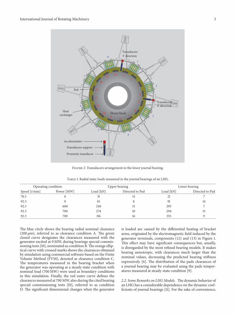
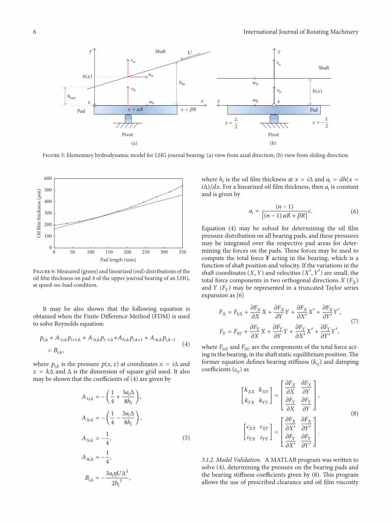
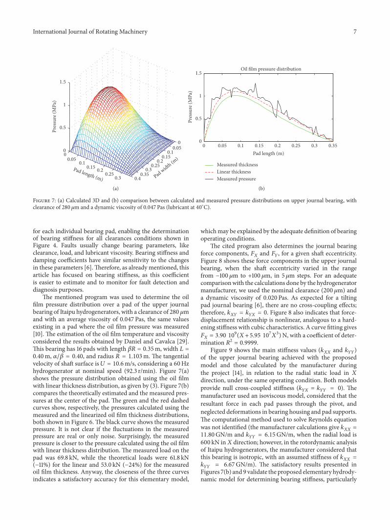
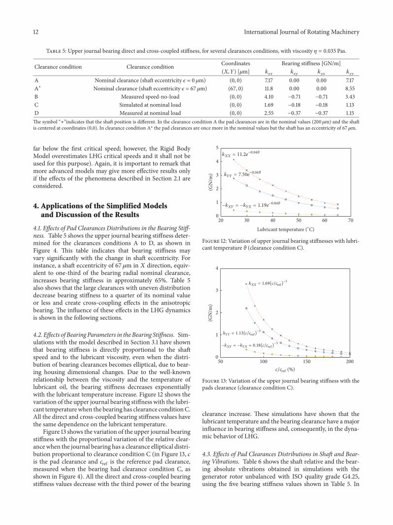
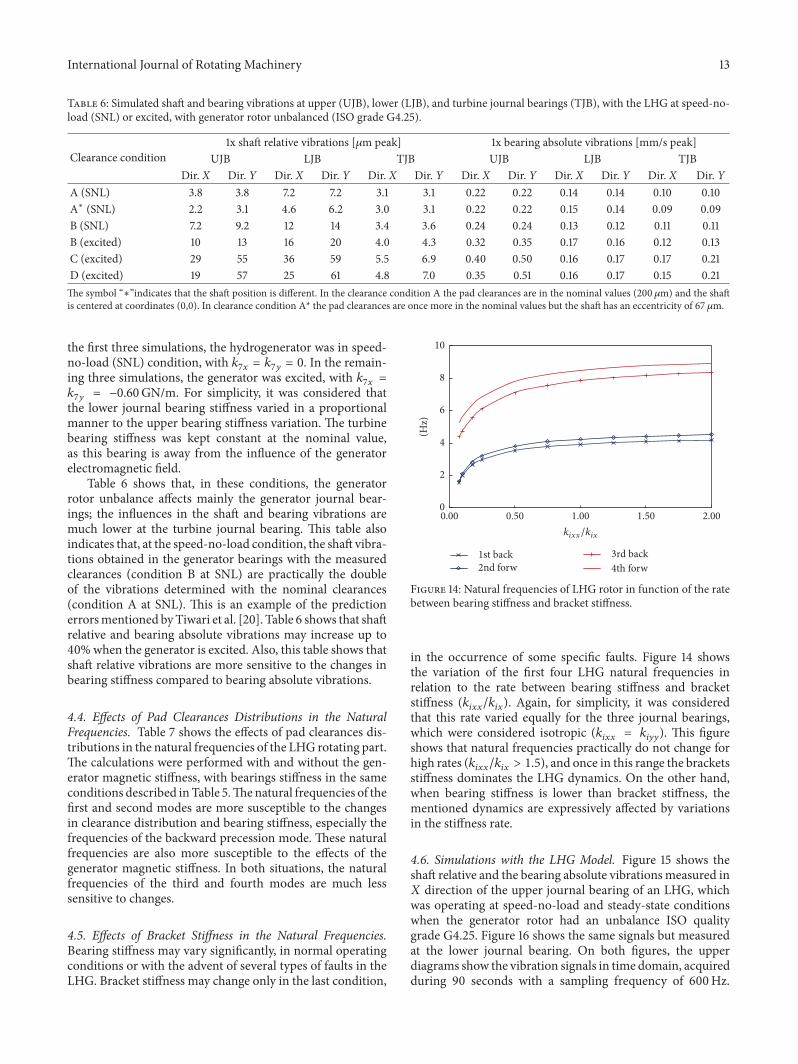