Embed Size (px)
Citation preview

Full Terms & Conditions of access and use can be found athttp://www.tandfonline.com/action/journalInformation?journalCode=tepe20
Download by: [ECU Libraries] Date: 25 March 2016, At: 16:23
EPE JournalEuropean Power Electronics and Drives
ISSN: 0939-8368 (Print) 2376-9319 (Online) Journal homepage: http://www.tandfonline.com/loi/tepe20
Optimized Control of Multi-Terminal DC GridsUsing Particle Swarm Optimization
Kumars Rouzbehi, Arash Miranian, Alvaro Luna & Pedro Rodriguez
To cite this article: Kumars Rouzbehi, Arash Miranian, Alvaro Luna & Pedro Rodriguez (2014)Optimized Control of Multi-Terminal DC Grids Using Particle Swarm Optimization, EPE Journal,24:2, 38-49, DOI: 10.1080/09398368.2014.11463883
To link to this article: http://dx.doi.org/10.1080/09398368.2014.11463883
Published online: 29 Oct 2015.
Submit your article to this journal
Article views: 8
View related articles
View Crossmark data
Kumars Rouzbehi, Arash Miranian, Alvaro Luna, Pedro Rodriguez
EPE Journal ⋅ Vol. 24 ⋅ no 2 ⋅ June 201438
Introduction
Recently, Multi-terminal DC (MTDC) grids have been receiving aspecial attention from the electric power systems researchers andalso from the industry professionals in this field. Therefore, themodeling, simulation and control of the MTDC grids are amongthe main research topics, pursued during the recent years [1-3].
The appropriateness of the MTDC grids for the integration of off-shore wind farms into the AC mainland, have been the main focusof various studies [4-6]. The MTDC grids eliminate the largecapacitive currents, associated with long-distance AC transmis-sion, and hence are suitable for wind farm integration into themainland AC grids [7]. Furthermore, the MTDC transmission sys-tem can facilitate the development of the so-called “EuropeanSupergrid” [8].The researches performed in the field of renewableenergies have launched other initiatives associated with theexploitation of other resources, such as Desertec and Medgrid,linked mainly to the exploitation, transmission and integration ofphotovoltaic (PV) generation systems [9].
The MTDC grids are usually characterized by the interconnectionof several high voltage DC (HVDC) stations through high voltageDC links [4]. Among the available HVDC technologies, i.e. theline-commutated converter (LCC)-HVDC and the voltage-sourceconverter (VSC)-HVDC, the latter exhibits more favorable fea-tures such as full controllability of the DC network and ease ofconnecting multiple converters to the same DC grid. Thus, theVSC-HVDC technology is considered as the prime candidate andthe most promising idea for constructing the VSC-MTDC grids [10].
In terms of network topology, the MTDC grids may be connectedin series or parallel. The parallel connections are further divided
into radial and meshed networks, where the meshed configurationwill be the most common topology [11].
The control of VSC-MTDC grids includes regulation of active andreactive power, control of DC voltage and regulation of AC voltageat the point of common coupling (PCC), resulting thus in a multiinput – multi output (MIMO) control system. The most commonlyused control strategy for the VSC-HVDC stations is based on thevector control [10-12]. This control technique, formed by inner andouter loop controllers, desirably allows the fully decoupled controlof the AC and DC quantities through transformation of AC quanti-ties into the direct-quadrature (dq) rotating reference frame [13].
In these applications the proportional-integral (PI) controllers arewidely used due to their simple structure and robust performanceover a wide range of operating conditions [14], to drive the controlled variable (e.g. active power and amplitude of the ACvoltage at the PCC) towards their target values.
However, to achieve a good control performance based on the useof vector control, which is adopted in this paper for the control ofa VSC stations, the corresponding PI controller’s parametersshould be optimally tuned and adjusted. The optimal tuning of thecontrollers will improve both transient and steady-state controlperformances. However, in case of the nonlinear systems andplants (e.g. voltage-source converters), it is quite difficult to tuneproperly the gains of the PI controllers [14, 15]. In such circum-stances, classical methods proposed for the tuning of the PI con-trollers face difficulties to determine an optimal or near optimal PIparameters [16].
In order to improve the performance of PI controllers variouscomputational intelligence (CI) approaches have been employed
Optimized Control of Multi-Terminal DC Grids Using Particle
Swarm Optimization
Kumars Rouzbehi1, Arash Miranian2, Alvaro Luna1, Pedro Rodriguez1,3
1 Technical university of Catalonia, Barcelona, Spain2 Islamic Azad University, Department of Electrical Engineering, College of Engineering, Mashhad Branch, Mashhad, Iran3 Abengoa Research, Seville, Spain
Keywords: «Multi-terminal DC grids», «Control», «Particle swarm optimization».
Abstract
The electric networks of the future will make an extensive use of DC grids. Therefore, the control of Multi-terminal DC(MTDC) grids is a key issue, which is gathering the attention of the industry and the research community. In this regard,this paper proposes a grid control strategy for voltage-source converter (VSC)-based MTDC networks, based on the useof the particle swarm optimization (PSO) technique. In the proposed approach, the controllers of the power convertersbelonging to the MTDC grid are acting based on the concept of vector control, in which the AC currents and voltagesare transformed into a rotating direct-quadrature (dq) reference frame for controlling of the active and reactive powersas well as the DC and AC voltages. Since the VSCs are nonlinear plants in nature, the classical approaches for tuning ofthe control system, which are usually based on the approximate linear model of the plants, do not lead to optimal results.As an alternative, in this paper an efficient PSO algorithm is used for tuning optimally the parameters of the controllersin the MTDC grid. In addition, the voltage droop control scheme is utilized to ensure the active power balance within theMTDC grid. The simulation results, obtained through a detailed model of a four-terminal DC grid, demonstrate the effi-ciency of the proposed approach. Finally a comparison with PI controllers which have been conventionally tuned alsoconfirmed the favorable performance of the proposed PSO-tuned controllers.
Dow
nloa
ded
by [
EC
U L
ibra
ries
] at
16:
23 2
5 M
arch
201
6

Optimized Control of Multi-Terminal DC Grids Using Particle Swarm Optimization
EPE Journal ⋅ Vol. 24 ⋅ no 2 ⋅ June 2014 39
over the past decade, as they are able to deal with nonlinear opti-mization problems. Genetic algorithm (GA) and particle swarmoptimization (PSO) are two well-known CI-based optimizationapproaches, adopted for optimal tuning of the parameters of PIcontrollers in different engineering applications [17-20].
In spite of the successful application of GA in many optimizationproblems, this technique suffers from some deficiencies such asconvergence issues [21]. On the other hand, the PSO algorithms,which are relatively modern heuristic algorithms and developedthrough simulation of a simplified social system, have shown to berobust in solving continuous nonlinear optimization problems anddo not exhibit problems associated with GA [22]. Moreover, thePSO algorithms are able to find a high-quality solution withinshorter calculation time and a more stable convergence characte-ristic compared to the other stochastic methods [14]. Interestingly,the potential of the PSO for complex problems of power systemshas been widely investigated, designating its suitability for powersystem applications [14, 20, 23].
Owing to the excellent features of the PSO as an optimizationtechnique and its satisfactory performance in optimal tuning of PIcontroller’s parameters, in this paper an optimized control strategybased on the particle swarm optimization algorithm is proposed.As the main contribution of this work in comparison to the avail-able literature, the PSO algorithm is employed to optimize theparameters of the inner and outer loop controllers for bettersteady-state and transient performances of the VSC stations in theMTDC grid. Then the optimized control strategy is employed for control of a four-terminal DC grid. To the best of author’sknowledge, the PSO technique has not been used to optimize thecontrollers parameters of the MTDC grids, previously.
Control of multi-terminal DC grids
VSC-MTDC grids are characterized by the interconnection ofseveral VSC-HVDC systems. Fig. 1 depicts the schematic dia-gram of a VSC-MTDC grid, where the interconnection of two ACnetworks as well as two offshore wind farms is proposed. As it canbe seen in the figure, the main components of the VSC-HVDC ter-minals include AC circuit breakers, AC transformers, AC filters,phase reactors, voltage source converters and DC capacitors.
The control of MTDC grids includes DC voltage regulation at theDC terminals, control of active and reactive power delivery at thepoint of common coupling and maintaining the AC voltage at thePCC within the specified set point. The vector control is the mostcommonly used technique for the control of the VSC-HVDC stations [10-13]. In this strategy the AC currents and voltages ofthe converter (at the PCC) are transformed into the rotating dqrefe-rence frame, which is synchronized with the AC grid voltageby means of a phase-locked loop (PLL).This method permits to
carry out a simple and decoupled control of the active and reactivepowers as well as an easier regulation of the DC and the AC voltages. The general architecture of the vector control at a VSC-HVDC station is illustrated in Fig. 2 [5]. It is worth to note thatthe outer controllers in Fig. 2 are responsible to generate the refe-rence currents for the inner current controller which determinesthe voltage reference of the converter in the dq frame.
Inner current controller
Considering the vector control technique based on the dqapproach, the inner current controller (ICC) includes fast PI con-trollers which are responsible for tracking of the reference cur-rents, set by the outer controllers, and produces the referencevoltages for the converter. To derive the structure of the ICC, thevoltage at PCC (es) and converter-side voltage (vc) are related by,
(1)
where, ic is the current flowing from the AC grid to the converterand RT and LT represent the equivalent resistance and inductancebetween the PCC and the converter (resistance and inductance ofthe phase reactor and LCL filter, including L1, L2 and C0, shownin Fig. 2), respectively. Then by applying the Park transformation,(1) can be expressed in the dq reference frame by,
(2)
(3)
where, ω is the angular frequency of the AC voltage at the PCC.
The structure of the ICC is obtained using (2)-(3) and it is shownin Fig. 3. The reference voltages (vd,ref and vq,ref) are then trans-formed back into the abc reference frame and used to generate theswitching signals for the IGBT´s of the converter.
Outer controllers
The outer controllers are comprised of the active and reactivechannels, as shown in Fig. 2. The active channel is responsible forthe regulation of the active power or the DC voltage level, whilethe reactive channel controls the reactive power delivery or ampli-tude of AC voltage at the PCC.
For active the power control, the power equations in the dq refer-ence frame can be written as [24],
e v R i Ldi
dtL iq q T q T
qT dω− = + +
e v R i Ldi
dtL id d T d T
dT qω− = + −
e v R i Ldi
dts c T c Tc− = +
Fig. 1: four-terminal HVDC grid composed of two AC grids and two wind farms
Dow
nloa
ded
by [
EC
U L
ibra
ries
] at
16:
23 2
5 M
arch
201
6

Kumars Rouzbehi, Arash Miranian, Alvaro Luna, Pedro Rodriguez
EPE Journal ⋅ Vol. 24 ⋅ no 2 ⋅ June 201440
P = vdid + vqiq (4)
Q = vqid – vdiq (5)
Note that the d-axis of the dq frame is alignedwith the AC network voltage phasor, detectedby a PLL; i.e. eq = 0 and hence,
P = vdid (6)
Q = – vdiq (7)
Based on (6) and (7), the current in dq axescan be employed to control active and reactivepowers, respectively. The AC voltage con-troller is intended to regulate the amplitude ofthe PCC’s AC voltage. This can be accom-plished by injecting the required amount ofreactive power such that the AC voltage at thePCC matches the given reference value.Likewise, the control of AC voltage is carriedout by modifying the q-axis current.
To maintain the DC voltage at its referencevalue, the active power exchanged with theAC grid must be properly regulated. Hence,modification of the d-axis current (id) allowsto control the DC voltage within the permissible limits.
Voltage droop control
The control of the DC voltage within an MTDC grid is of utmostimportance, as this value can only vary in a narrow band. The voltage level at different terminals of the MTDC grids directlyinfluences the flow of DC power between the MTDC terminals. Itis worth noting that unlike AC transmission systems, where fixedand identical voltage amplitudes (normally 1 pu) are preferredthroughout the system, the MTDC grids cannot have an identicalvoltage level over the entire system. Obviously, if the level of DCvoltage throughout the grid is the same, there will be no flow ofpower between the DC terminals.
The voltage droop control permits to carry out the regulation ofthe DC voltage in the grid by adjusting the converter’s currents insuch a way that the power balance is guaranteed throughout thegrid [12]. In this method a proportional controller is employedwhich represents a droop characteristic describing a unique rela-tion between the DC voltage and the converter's current. A typicalvoltage droop characteristic is shown in Fig. 4. In this paper, avoltage droop control is implemented on the grids-side VSCs,which normally receive the power generated by the generationfacilities, to guarantee the power balance within the MTDC grid.The parameters of the voltage droop controllers are adjusted suchthat the maximum and minimum values of the DC voltage occurat the maximum converter's power.
Optimization of controllers
The performance of the control system in MTDC grids is sub-stantially influenced by the proper tuning of the VSC controller’sparameters. Owing to this profound effect, the optimal positioningof the controller’s parameters is of great interest. In this paper, theheuristic algorithm of PSO has been employed for the optimiza-tion of each VSC controller. As it was stated in the introduction,the PSO method has been applied to a wide range of optimizationproblems in electrical systems such as parameter optimization ofpower system stabilizer (PSS) [20], automatic voltage regulator(AVR) [14], and wind generator (WG) [23].
PSO algorithms provide several advantageous features such as,the speed of convergence, the simplicity of implementation and alower susceptibility of being trapped in local optimal point [25].Interestingly, they can easily coded in a simple and straightfor-ward manner. In PSO, particles flow in a multi-dimensional searchspace and the position of each particle is tuned based on the expe-riences gained by the particle and its neighbors. In this paper aglobal best (gbest) PSO algorithm has been adopted. In gbestalgorithm the new position of the ith particle is found by addingthe velocity component, as follows:
Fig. 2: General architecture of the dq vector control for a VSC-HVDC station
Fig. 3: Strucuture of the ICC
Fig. 4: Voltage droop characteristics
Dow
nloa
ded
by [
EC
U L
ibra
ries
] at
16:
23 2
5 M
arch
201
6

Optimized Control of Multi-Terminal DC Grids Using Particle Swarm Optimization
EPE Journal ⋅ Vol. 24 ⋅ no 2 ⋅ June 2014 41
(8)
(9)
where, xi(t) is the position of particle i at time t, vij(t) is velocity ofparticle i at dimension j at time t, yi(t) is the best position, pbesti,found by particle i, ^y(t) is the best position found by swarm, gbest,N is the number of particles in the swarm, P is the dimension ofeach particle, and are acceleration constants and r1(t) and r2(t) areuniformly distributed number in [0,1].
The optimization process by PSO requires the definition of a fit-ness function or a performance index. In this paper, the perfor-mance index (I) is defined based on the minimization of theintegral of time multiplied by absolute error (ITAE), as expressedbelow,
(10)
where, T is the duration of optimization and hr and hm are the refe-rence and measured values of the output, respectively. The errorterm in (10) indicates the error of inner or outer controllers. ThePSO algorithm tries to minimize the performance index I over thesimulation period, in an offline mode. Then, the optimized con-trollers will be used for control of MTDC grid. The procedure ofPSO algorithm is illustrated by Fig. 5. To provide more insightinto the implementation of the PSO algorithm, the following pseudo-code is presented:
Step 1 - Initialization of PSO parameters: Set the appropriate values for number of particles (N), dimension of each particle (P),and acceleration constants (k1 and k2). Large number of particlesincreases the search space of the algorithm but results in highcomputational burden. Hence a trade-off must be consideredaccording to the type of the problem. The parameter P (dimensionof particles) is equal to the number of unknown parameters in theoptimization problem.
Step 2 - Generate random population: The initial position of theparticles must be determined prior to execution of the optimiza-tion. This can be accomplished by means of a function producingrandom numbers, e.g. rand( ) in MATLAB. If a suboptimal solu-tion for the optimization problem is available, the particles may bescattered around this solution for a faster convergence.
Step 3- Calculate pbest of each particle and gbest of the swarm:Calculate the performance index in (10) for each particle and setthe pbest of each particle to its initial position. Then, find the bestposition among all particles, i.e. particle with lowest performanceindex, and set this position as the gbest.
Step 4- Update particles’ position and velocity: Update the velo-city and then position of each particle using (8) and (9) respec-tively.
Step 5- Calculate fitness of particles: Calculate the fitness of theupdated position of each particle using performance index (10).
Step 6- Update bpest and gbest: For each particle, update the pbestusing the following:If I(xi_updated) < I(pbesti), then pbesti = xi_updatedThen, update the gbest of the swarm as stated below,gbest = min(pbesti), i = 1, …, N
t h h dtMinimize I r m0
T∫= −
v t v t k r t y t x t
k r t y t x t
i N j P
( 1) ( ) ( ) ( ) ( )
( ) ( ) ( )
1, , , 1, ,
ij ij 1 1j ij ij
2 2j j ij$
+ = + −
+ −
= … = …
x t x t v t i N( 1) ( ) ( 1), 1, ,i i i+ = + + = …
Fig. 5: Flow chart of PSO algorithm for optimal tuning of PIcontrollers
Fig. 6: Optimization of inner current and outer controllers byPSO
Dow
nloa
ded
by [
EC
U L
ibra
ries
] at
16:
23 2
5 M
arch
201
6

Kumars Rouzbehi, Arash Miranian, Alvaro Luna, Pedro Rodriguez
EPE Journal ⋅ Vol. 24 ⋅ no 2 ⋅ June 201442
Step 7- Check termination condition: If termination condition ismet, stop the algorithm and output the final gbest as the problemsolution; otherwise go back to step 4. The termination criterioncan be the maximum number of iterations or a desirable value forthe performance index.
For performing a fine tuning of the ICC and the outer controllers,the optimization procedure shown in Fig. 6 is employed. Based onthis procedure, first the parameters of ICC are optimized by thePSO algorithm. Then, the optimized ICC is integrated into theVSC control framework and the parameters of the outer con-trollers are tuned by the PSO algorithm.
Tuning of inner current controller
The circuit diagram for the optimization of the inner current con-troller is illustrated in Fig. 7. According to Fig. 7, a step signal inthe d-axis is used as the reference current input to the ICC and theparameters of the PI controller, i.e. KI,P and KI,I are optimized byexecuting the PSO procedure. Since the PI controllers of the ICCare identical for both d-axis and q-axis, the step input is onlyapplied to the d-axis current while a zero input is considered forthe q-axis as shown in Fig. 7. For optimization of the ICC, the hrand hm in (10) correspond to reference d-axis current and mea-sured d-axis current, respectively, as stated below,
(11)
Tuning of outer controllers
After tuning of the ICC, the optimization of the outer controllersis carried out. This is achieved based on the schematic diagramshown in Fig. 8. Clearly, the tuned ICC is used in the VSC controlframework and then the outer controller is optimized by the PSO.While Fig. 8 depicts the optimization of the active power con-troller but other outer controllers can be tuned in a similar manner.The objective function for this optimization problem is expressedbelow,
(12)
Simulation results
To assess performance of the proposed controllers, a four-terminaltest system, shown in Fig. 1, is used. The test system is composedof two AC grids with nominal voltage level of 220 kV and ratedpower of 2 GW and two offshore wind farms with rated voltage of33 kV and capacity of 150 MW. The nominal voltage of the DCgrid is ± 150 kV.
The parameters of the MTDC grid are presented in Table I. Thedetailed model of the test four-terminal DC grid is used to performthe simulations and validate the performance of the proposed con-trollers.
The simulations include the evaluation of the step response of theoptimized controllers, and MTDC performance in case of varia-tions in wind farm outputs through time and occurrence of a three-phase AC fault on AC grid 1.
Assessment and comparison of optimized controller’s performance
First, the parameters of the controllers are optimized by PSO algo-rithm based on the minimization of the objective function definedby (10). The parameters of the PSO algorithm are presented in Table
∫= −I t P P tMinimize dIOC ref0
T
∫= −I t i i tMinimize dICC d d,ref0
T
II. For the purpose of comparison, a classically tuned PI (C-PI) con-troller is also implemented and tested during the simulations.
Classical tuning of ICC
The parameters of the C-PI controllers are tuned using followingideas [11]:
– in order to achieve a satisfactory performance, the ICC closed-loop bandwidth should not be higher than 1/5 of the angularswitching frequency; – the outer controllers must be at least 10 times slower than theICC to obtain a closed-loop system without oscillatory response;
Fig. 7: Tuning of the ICC by PSO
Fig. 8: Tuning of the active power controller by PSO
Dow
nloa
ded
by [
EC
U L
ibra
ries
] at
16:
23 2
5 M
arch
201
6
Optimized Control of Multi-Terminal DC Grids Using Particle Swarm Optimization
EPE Journal ⋅ Vol. 24 ⋅ no 2 ⋅ June 2014 43
based on the abovementioned rules, the parameters of the PI con-troller for the ICC can be chosen as [26],
KI,P = αcLpuT (13)
KI,I = αcRpuT (14)
where, αc is the closed loop bandwidth of the ICC. Since theswitching frequency in this paper is set to 2 kHz, then,
(15)
Considering the safety margins, the value of 2 krad/s is chosen forBased on (13) and (14) and the parameters presented in Table I,the parameters of the ICC are computed and presented in Table III.
Classical tuning of outer controllers
The parameters of the outer controllers can be tuned similarly andbased on the fact that the outer controllers must be at least 10times slower than the ICC to obtain a closed-loop system withoutoscillatory response. Hence, the bandwidth of the outer con-trollers, αoc, can be calculated as,
αoc = 0.1 αc (16)
Then, based on the idea presented in [26] the proportional andintegral coefficients of outer controllers can be derived using (17)-(18),
KO,P = αocCpu (17)
KO,I = α2ocCpu (18)
The parameters of the active power controller, achieved by usingclassical tuning method in (17) and (18), are shown in Table III.
Optimal tuning of ICC and outer controllers by PSO
First, it must be noted that all converter stations in Fig. 1 are iden-tical. Hence, optimization of control system is carried out for one
2 2
52.5 krad/scα <
×π×=
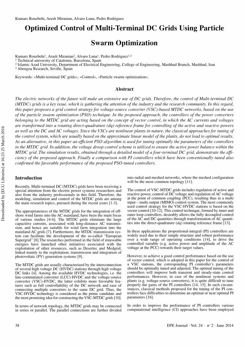
Table I: Parameters of the MTDC grid
Model Rated voltage (kV) Impedance Description
AC networks 220 0.001 + j0.15 pu 2000 MVAWind farms 33 0.002 + j0.1 pu 150 MVA
Phase reactor 180 0.01 + 0.15 pu -DC capacitor ± 150 Two 100 µF capacitors -
connected in seriesR = 1.13 × 10⁻² Ω/km
DC link ± 150 L = 1.59 × 10⁻⁴ H/km 100 km between all stationsC = 2.3100 × 10⁻⁷ F/km
Table II: Parameters of PSO algorithm
Parameter Particles dimension Number of initial population Number of iterations k1 and k2
Value 2 30 15 2
Table III: Parameters of PI controllers obtained by PSO and classical tuning for ICC and active power controller
Controller Classical tuning PSO tuningkp ki kp ki
ICC 0.95 10.00 1.23 15.45Active power controller 0.54 81.00 0.68 75.22
Fig. 9: Performance of PSO algorithm for optimization ofICC
Fig. 10: Evolution of coefficient KI,I (i.e. integral gain of ICC)during optimization
Dow
nloa
ded
by [
EC
U L
ibra
ries
] at
16:
23 2
5 M
arch
201
6

Kumars Rouzbehi, Arash Miranian, Alvaro Luna, Pedro Rodriguez
EPE Journal ⋅ Vol. 24 ⋅ no 2 ⋅ June 201444
VSC and then the optimized controlparameters are adopted in otherVSCs. The initial positions of thePSO particles are scattered aroundthe solution of classical tuning.
In order to achieve an optimal tuningof the controller’s parameter, thePSO algorithm is executed. Fig. 9shows the value of the fitness func-tion during the optimization of theICC by the PSO algorithm.Moreover, evolution of coefficient KI,I(i.e. integral gain of the ICC) duringthis optimization has been shown inFig. 10. The parameters of the outercontrollers are tuned similarly byapplying the PSO. The values ofparameters for ICC and active powercontroller obtained by the PSO andtuning approach in [11] are presentedin Table III. After the optimization ofthe controllers, the performance ofthe control system is examined. Thisincludes the response of the ICC andthe outer controllers to a step changeinput. The step response of the PSO-optimized ICC for the d-axis currentis shown in Fig. 11. The responseobtained by the C-PI controller isalso depicted in Fig. 11. Clearly, theproposed optimized controllerexhibits a better performance, specifi-cally faster rise time, than the oneprovided by the C-PI controller. For amore detailed comparison, the profileof the active power and DC voltage,obtained by the C-PI and PSO-PI areshown in Fig. 12 and Fig. 13, respec-tively.
For further investigations, the perfor-mance of the active power controllerwhen there is a reference step in thepower is illustrated in Fig. 14. Fromthis figure it can be concluded thatthe optimized controller has a favor-able performance for the referencepower step input with a fasterresponse, in comparison to the C-PIcontroller. To present a sensiblenumerical assessment for the perfor-mance of C-PI and PSO-PI con-trollers, they are compared in termsof ITAE measure, defined by (10), isTable IV. The results of this tableindicate better performance of theproposed approach over classicaltuning method.
Application to MTDC grid control
The grid-side converters of the MTDC grid in Fig. 1 include voltagedroop control in their active channel to share the generated powerby the offshore wind farms. The droop characteristics converterstations 1 and 2 are illustrated in Fig. 15, showing -2 pu as thelower current limit of both droop characteristics. This limit indi-cates that the grid-side VSCs cannot absorb currents larger than 2pu. Moreover, the slope of voltage droop characteristics for AC
grid 1 is smaller compared to the AC grid 2. Hence, it’s expectedthat AC grid 1 absorbs larger portion of the power generation bythe wind farms.
It must be noted that the reactive channel on grid-side convertersoperates on reactive power control, trying to control the powerfactor at unity by annulling the reactive power exchanged with theAC grids. On the other hand, the reactive channel of wind farmconverters is operated on AC voltage control mode to fix theamplitude of the AC voltage at a specified set point.
Fig. 11: Step response of ICC
Fig. 12: Active power resulted from classically- and PSO-tuned ICC
Fig. 13: DC voltage resulted from classically- and PSO-tuned ICC
Fig. 14: Step response of the active power controller
Dow
nloa
ded
by [
EC
U L
ibra
ries
] at
16:
23 2
5 M
arch
201
6

Optimized Control of Multi-Terminal DC Grids Using Particle Swarm Optimization
EPE Journal ⋅ Vol. 24 ⋅ no 2 ⋅ June 2014 45
In order to investigate the control performance of the proposedapproach within an MTDC grid, the wind generation as well as thefault scenarios presented in Table V and Table VI, respectively, areapplied. These scenarios include the step changes in the outputpowers of the wind farms and a three-phase short-circuit fault onAC grid 1.
Wind power sharing between grid-side converters
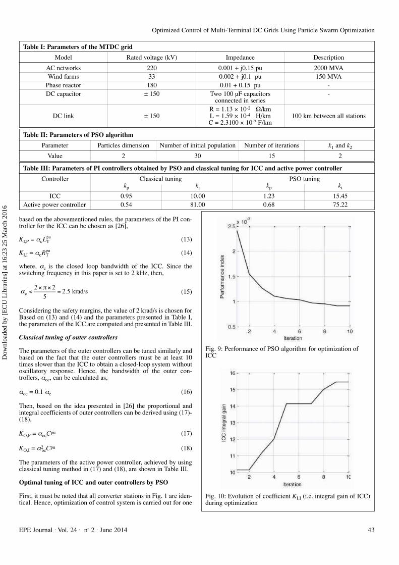
The simulation starts with 0.4 and 0.8 pu of generation by thewind farms 1 and 2, respectively. This condition continues until t = 0.5 sec. The active power at the PCC of each VSC-HVDC sta-tion is shown in Fig. 16 and the d-axis current for AC grids 1 and2 are depicted in Fig. 17. At t = 0.5 sec, the power generated bythe wind farm 1 increases to 1.2 pu. It’s seen that the grid-sideVSCs quickly follow the changes in the output power of the windfarms. Moreover, AC grid 1 absorbs larger portion of wind powercompared to AC grid 2. As stated earlier, this can be justifiedbased on the voltage droop characteristics shown in Fig. 15.Obviously, the voltage-droop characteristic of AC grid 1 has a lowerminimum voltage setting (VDC,min) and lower slope in comparisonto characteristic of AC grid 2. Hence, AC grid 1 has priority inreceiving power over AC grid 2. Finally, at t = 0.8 sec, the powergenerated by wind power 2 rises to 0.8 pu and the excessive poweris shared between grid-side VSCs according to their voltage-droopcharacteristics. The voltage profiles at the DC terminals of theMTDC grid during the simulation are depicted in Fig. 18.
To compare performance of the PSO-tuned and classically-tunedcontrol systems, the DC voltage at VSC-HVDC station 1 is shownin Fig. 19, indicating more satisfactory performance of the pro-posed PSO-tuned control system with faster speed.
Performance against fault on AC grid
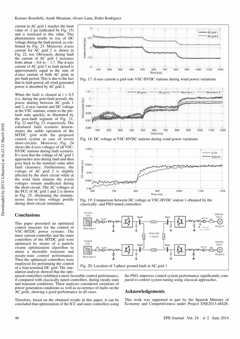
A stable performance of the MTDC grid against short-circuit faultmust be assessed. For such an assessment, a three-phase fault withfault resistance on 0.05 Ω is applied on AC grid 1, as shown in Fig.20, at t = 0.3 sec and cleared at t = 0.7 sec, according to Table VI.Prior to the short-circuit, the wind farms 1 and 2 are generating 1.2
and 0.8 pu of power, shared betweenthe grid-side converters based on theirvoltage droop characte-ristics. Theactive powers of all VSC stations during this simulation are depicted inFig. 21. Based on Fig. 21, when faulthappens AC grid 1 at t = 0.3 sec, all thegenerated power by the wind farms isquickly transmitted to AC grid 2 whilethe AC power at AC grid 1 is reduced tozero.
The d-axis current of both AC grids areshown in Fig. 22. It’s seen from this Fig. that during the fault state, the d-axis
Table IV: Comparison between classically- and PSO-tunedPI controllers in terms of ITAE measure
Controller ITAEClassical tuning PSO tuning
ICC 3.08 × 10⁻⁴ 9.81 × 10⁻⁵
Active power controller 1.33 × 10⁻³ 7.62 × 10⁻⁴
Fig. 15: Voltage droop characteristics of (a) AC grid 1 and (b)AC grid 2
Table V: Wind generation scenarios
Event time t = 0 sec t = 0.5 sec t = 0.8 sec
Wind farm 1 power pu 0.4 0.4 0.8Wind farm 2 power pu 0.8 1.2 1.2
Table VI: AC fault scenario
Event time t = 0 sec t = 0.3 sec t = 0.5 sec
Wind farm 1 power pu 1.2 1.2 1.2Wind farm 2 power pu 0.8 0.8 0.8AC fault on AC grid 1 No fault Fault occurrence Fault clearance
Fig. 16: Active power at VSC-HVDC stations during wind power variations
Dow
nloa
ded
by [
EC
U L
ibra
ries
] at
16:
23 2
5 M
arch
201
6
Kumars Rouzbehi, Arash Miranian, Alvaro Luna, Pedro Rodriguez
EPE Journal ⋅ Vol. 24 ⋅ no 2 ⋅ June 201446
current in AC grid 1 reaches the limitvalue of -2 pu (indicated by Fig. 15)and is restricted to this value. Thisphenomenon results in rise of DCvoltage during the fault period, as con-firmed by Fig. 23. Moreover, d-axiscurrent for AC grid 2 is shown in Fig. 22, too. Obviously, during faultthe current of AC grid 2 increasesfrom about – 0.6 to – 1.7. The d-axiscurrent of AC grid 2 in fault period isapproximately equal to the sum of d-axes current of both AC grids in pre-fault period. This is due to the factthat in fault period, all wind generatedpower is absorbed by AC grid 2.
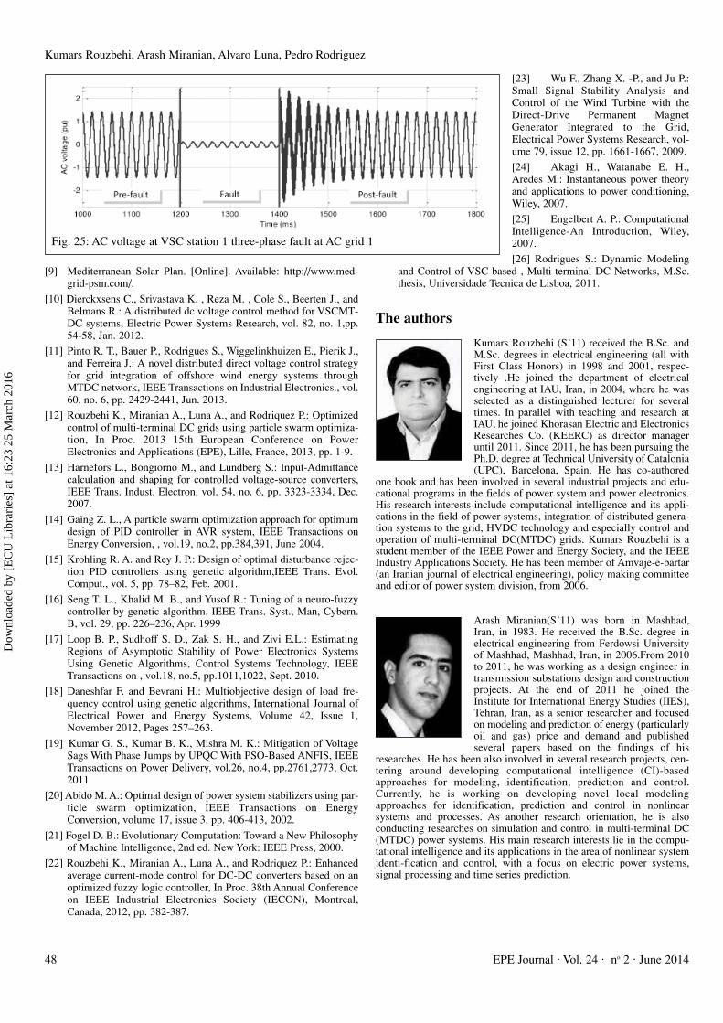
When the fault is cleared at t = 0.5(i.e. during the post-fault period), thepower sharing between AC grids 1and 2, d-axis current and DC voltageat the VSC stations, return to the pre-fault state quickly, as illustrated bythe post-fault segment of Fig. 21,Fig. 22 and Fig. 23, respectively. Thesimulated fault scenario demon-strates the stable operation of theMTDC grid with the proposed control system in case of severeshort-circuits. Moreover, Fig. 24shows the d-axis voltages of all VSC-HVDC stations during fault scenario.It’s seen that the voltage of AC grid 1approaches zero during fault and thengoes back to the nominal value afterfault clearance. Furthermore, thevoltage of AC grid 2 is slightlyaffected by the short circuit while atthe wind farm stations the d-axisvoltages remain unaffected duringthe short-circuit. The AC voltages atthe PCC of AC grid 1 and 2 is shownin Fig. 25, illustrating the instanta-neous line-to-line voltage profile during short-circuit simulation.
Conclusions
This paper presented an optimizedcontrol structure for the control ofVSC-MTDC power systems. Theinner current controller and the outercontrollers of the MTDC grid wereoptimized by means of a particleswarm optimization algorithm toattain a desirable transient andsteady-state control performance.Then the optimized controllers wereemployed for performing the controlof a four-terminal DC grid. The sim-ulation analysis showed that the opti-mized controllers exhibited a more favorable control performance,if compared with classically tuned controllers, during steady-stateand transient conditions. These analyses considered variations ofpower generation conditions as well as occurrence of faults on theAC grids, showing a good performance in all cases.
Therefore, based on the obtained results in this paper, it can beconcluded that optimization of the ICC and outer controllers using
the PSO, improves control system performance significantly com-pared to control system tuning using classical approaches.
Acknowledgements
This work was supported in part by the Spanish Ministry ofEconomy and Competitiveness under Project ENE2013-48428-
Fig. 17: d-axis current a grid-side VSC-HVDC stations during wind power variations
Fig. 18: DC voltage at VSC-HVDC stations during wind power variations
Fig. 19: Comparison between DC voltage at VSC-HVDC station 1 obtained by the classically- and PSO-tuned controllers
Fig. 20: Location of 3-phase ground-fault at AC grid 1
Dow
nloa
ded
by [
EC
U L
ibra
ries
] at
16:
23 2
5 M
arch
201
6
Optimized Control of Multi-Terminal DC Grids Using Particle Swarm Optimization
EPE Journal ⋅ Vol. 24 ⋅ no 2 ⋅ June 2014 47
C2-2-R . Any opinions, findings, andconclusions or recommendationsexpressed in this material are those ofthe authors and do not necessarilyreflect those of the host institutionsor founders.
References
[1] Colas R. F., Guillaud X., andNguefeu S.: Method for small sig-nal stability analysis of VSC-MTDC grids, 2012 IEEE Powerand Energy Society GeneralMeeting, San Diego, US, pp. 1-7.
[2] Beerten J., Cole S., and BelmansR.: Generalized steady-state VSCmtdc model for sequential AC/DCpower flow algorithms, IEEETrans. Power Syst., vol. 27, no. 1,pp. 821-829, May 2012.
[3] Rouzbehi K., Miranian A., LunaA., and Rodriquez P.: A generalizedvoltage droop strategy for controlof multi-terminal DC grids, 2013IEEE Energy Conversion Congressand Exposition (ECCE), Denver,US, pp. 59-64.
[4] Jiao L., Joos G., Abbey C.,Fengquan Z., and Ooi B.T: Multi-terminal DC (MTDC) system forwind farms powered by doubly-fedinduction generators (DFIGs),IEEE Annual Power ElectronicsSpecialists Conference (PESC 04),2004, pp. 1413-1418.
[5] Chaudhuri N. R., Majumder R.,Chaudhuri B., Pan J., and NuquiR.: Modeling and stability analysisof MTDC grids for offshore windfarms: A case study on the NorthSea benchmark system, 2011 IEEEPower and Energy Society GeneralMeeting, San Diego, USA, pp. 1-7.
[6] Livermore L., Liang J., andEkanayake J.: MTDC VSC tech-nology and its applications forwind power, 45 th InternationalUniversities Power EngineeringConference (UPEC), Cardiff, UK,2010, pp. 1-6.
[7] Xu L. X., Williams B. W., and YaoL.: Multi-terminal DC transmissionsystems for connecting large off-shore wind farms,2008 IEEEPower and Energy Society GeneralMeeting Conversion and Deliveryof Electrical Energy in the 21stCentury (2008).
[8] Cole S., Karoui K., Vrana T. K.,Fosso O., Curis J. B., Denis A. M.,and Liu C. C.: EuropianSupergrid:Present State and FutureChallenges, 17th Power SystemsComputation Conference StockholmSweden - August 22-26, 2011.
Fig. 21: Active power at VSC-HVDC stations during three-phase fault at AC grid 1
Fig. 22: d-axis current at grid-side VSC-HVDC stations during three-phase fault at AC grid 1
Fig. 23: DC voltage at VSC-HVDC stations during three-phase fault at AC grid 1
Fig. 24: d-axis voltage at all VSC stations during three-phase fault at AC grid 1
Dow
nloa
ded
by [
EC
U L
ibra
ries
] at
16:
23 2
5 M
arch
201
6
Kumars Rouzbehi, Arash Miranian, Alvaro Luna, Pedro Rodriguez
EPE Journal ⋅ Vol. 24 ⋅ no 2 ⋅ June 201448
[9] Mediterranean Solar Plan. [Online]. Available: http://www.med-grid-psm.com/.
[10] Dierckxsens C., Srivastava K. , Reza M. , Cole S., Beerten J., andBelmans R.: A distributed dc voltage control method for VSCMT-DC systems, Electric Power Systems Research, vol. 82, no. 1,pp.54-58, Jan. 2012.
[11] Pinto R. T., Bauer P., Rodrigues S., Wiggelinkhuizen E., Pierik J.,and Ferreira J.: A novel distributed direct voltage control strategyfor grid integration of offshore wind energy systems throughMTDC network, IEEE Transactions on Industrial Electronics., vol.60, no. 6, pp. 2429-2441, Jun. 2013.
[12] Rouzbehi K., Miranian A., Luna A., and Rodriquez P.: Optimizedcontrol of multi-terminal DC grids using particle swarm optimiza-tion, In Proc. 2013 15th European Conference on PowerElectronics and Applications (EPE), Lille, France, 2013, pp. 1-9.
[13] Harnefors L., Bongiorno M., and Lundberg S.: Input-Admittancecalculation and shaping for controlled voltage-source converters,IEEE Trans. Indust. Electron, vol. 54, no. 6, pp. 3323-3334, Dec.2007.
[14] Gaing Z. L., A particle swarm optimization approach for optimumdesign of PID controller in AVR system, IEEE Transactions onEnergy Conversion, , vol.19, no.2, pp.384,391, June 2004.
[15] Krohling R. A. and Rey J. P.: Design of optimal disturbance rejec-tion PID controllers using genetic algorithm,IEEE Trans. Evol.Comput., vol. 5, pp. 78–82, Feb. 2001.
[16] Seng T. L., Khalid M. B., and Yusof R.: Tuning of a neuro-fuzzycontroller by genetic algorithm, IEEE Trans. Syst., Man, Cybern.B, vol. 29, pp. 226–236, Apr. 1999
[17] Loop B. P., Sudhoff S. D., Zak S. H., and Zivi E.L.: EstimatingRegions of Asymptotic Stability of Power Electronics SystemsUsing Genetic Algorithms, Control Systems Technology, IEEETransactions on , vol.18, no.5, pp.1011,1022, Sept. 2010.
[18] Daneshfar F. and Bevrani H.: Multiobjective design of load fre-quency control using genetic algorithms, International Journal ofElectrical Power and Energy Systems, Volume 42, Issue 1,November 2012, Pages 257–263.
[19] Kumar G. S., Kumar B. K., Mishra M. K.: Mitigation of VoltageSags With Phase Jumps by UPQC With PSO-Based ANFIS, IEEETransactions on Power Delivery, vol.26, no.4, pp.2761,2773, Oct.2011
[20] Abido M. A.: Optimal design of power system stabilizers using par-ticle swarm optimization, IEEE Transactions on EnergyConversion, volume 17, issue 3, pp. 406-413, 2002.
[21] Fogel D. B.: Evolutionary Computation: Toward a New Philosophyof Machine Intelligence, 2nd ed. New York: IEEE Press, 2000.
[22] Rouzbehi K., Miranian A., Luna A., and Rodriquez P.: Enhancedaverage current-mode control for DC-DC converters based on anoptimized fuzzy logic controller, In Proc. 38th Annual Conferenceon IEEE Industrial Electronics Society (IECON), Montreal,Canada, 2012, pp. 382-387.
[23] Wu F., Zhang X. -P., and Ju P.:Small Signal Stability Analysis andControl of the Wind Turbine with theDirect-Drive Permanent MagnetGenerator Integrated to the Grid,Electrical Power Systems Research, vol-ume 79, issue 12, pp. 1661-1667, 2009.
[24] Akagi H., Watanabe E. H.,Aredes M.: Instantaneous power theoryand applications to power conditioning,Wiley, 2007.
[25] Engelbert A. P.: ComputationalIntelligence-An Introduction, Wiley,2007.
[26] Rodrigues S.: Dynamic Modelingand Control of VSC-based , Multi-terminal DC Networks, M.Sc.thesis, Universidade Tecnica de Lisboa, 2011.
The authors
Kumars Rouzbehi (S’11) received the B.Sc. andM.Sc. degrees in electrical engineering (all withFirst Class Honors) in 1998 and 2001, respec-tively .He joined the department of electricalengineering at IAU, Iran, in 2004, where he wasselected as a distinguished lecturer for severaltimes. In parallel with teaching and research atIAU, he joined Khorasan Electric and ElectronicsResearches Co. (KEERC) as director manageruntil 2011. Since 2011, he has been pursuing thePh.D. degree at Technical University of Catalonia(UPC), Barcelona, Spain. He has co-authored
one book and has been involved in several industrial projects and edu-cational programs in the fields of power system and power electronics.His research interests include computational intelligence and its appli-cations in the field of power systems, integration of distributed genera-tion systems to the grid, HVDC technology and especially control andoperation of multi-terminal DC(MTDC) grids. Kumars Rouzbehi is astudent member of the IEEE Power and Energy Society, and the IEEEIndustry Applications Society. He has been member of Amvaje-e-bartar(an Iranian journal of electrical engineering), policy making committeeand editor of power system division, from 2006.
Arash Miranian(S’11) was born in Mashhad,Iran, in 1983. He received the B.Sc. degree inelectrical engineering from Ferdowsi Universityof Mashhad, Mashhad, Iran, in 2006.From 2010to 2011, he was working as a design engineer intransmission substations design and constructionprojects. At the end of 2011 he joined theInstitute for International Energy Studies (IIES),Tehran, Iran, as a senior researcher and focusedon modeling and prediction of energy (particularlyoil and gas) price and demand and published several papers based on the findings of his
researches. He has been also involved in several research projects, cen-tering around developing computational intelligence (CI)-basedapproaches for modeling, identification, prediction and control.Currently, he is working on developing novel local modelingapproaches for identification, prediction and control in nonlinear systems and processes. As another research orientation, he is also conducting researches on simulation and control in multi-terminal DC(MTDC) power systems. His main research interests lie in the compu-tational intelligence and its applications in the area of nonlinear systemidenti-fication and control, with a focus on electric power systems,signal processing and time series prediction.
Fig. 25: AC voltage at VSC station 1 three-phase fault at AC grid 1
Dow
nloa
ded
by [
EC
U L
ibra
ries
] at
16:
23 2
5 M
arch
201
6

Optimized Control of Multi-Terminal DC Grids Using Particle Swarm Optimization
EPE Journal ⋅ Vol. 24 ⋅ no 2 ⋅ June 2014 49
Alvaro Luna (S’07–M’10) received the B.Sc.,M.Sc., and Ph.D. degrees from the TechnicalUniversity of Catalonia (UPC), Barcelona, Spain,in 2001, 2005, and 2009, respectively, all in elec-trical engineering.He joined as a Faculty Memberat UPC in 2005, where he is currently anAssistant Professor. His research interestsinclude wind turbines control, integration of dis-tributed generation, and power conditioning. Dr.Luna is a Member of the IEEE Power ElectronicsSociety, the IEEE Industrial Electronics Society,and the IEEE Industrial Applications Society.
Pedro Rodriguez (S’99–M’04–SM’10-F’14)Pedro Rodríguez received the M.Sc. and Ph.D.degrees in electrical engineering from theTechnical University of Catalonia (UPC), Spain,in 1994 and 2004, respectively. He was aPostdoctoral Researcher at the Center for PowerElectronics Systems (CPES), Virginia Tech,Blacksburg in 2005, and at the Department ofEnergy Technology, Aalborg University (AAU)in 2006. He joined the faculty of UPC as anAssistant Professor in 1990, where he became theDirector of the research center on Renewable
Electrical Energy Systems (SEER) in the Department of ElectricalEngineering. He was also a Visiting Professor at the AAU from 2007 to2011, acting as a co-supervisor of the Vestas Power Program. He stilllectures Ph.D. courses at the AAU every year. From 2011, he is the Headof Electrical Engineering division in Abengoa Research, although he isstill joined to the UPC as a part time Professor. He has coauthored onebook and more than 200 papers in technical journals and conferenceproceedings. He was given the Best Technical Letter Award 2012 andthe Second Best Paper Award 2012 by the IEEE Transactions on PowerElectronics. He is the holder of seven licensed patents. His researchinterests include integration of distributed generation systems, smartgrids, and design and control of power converters. Dr. Rodriguez is afellow of the IEEE, a member of the administrate committee of theIEEE Industrial Electronics Society (IES), the general chair of IEEE-IES Gold and Student Activities, the vice-chair of the Sustainability andRenewable Energy Committee of the IEEE Industry Application Societyand a member of the IEEE-IES Technical Committee on RenewableEnergy Systems. Dr. Rodriguez is member of the Horizon 2020Advisory Group on Energy. He is an Associate Editor of the IEEETransaction on Power Electronics.
Dow
nloa
ded
by [
EC
U L
ibra
ries
] at
16:
23 2
5 M
arch
201
6