Embed Size (px)
Citation preview

Using Mobile Devices for Robotic Controllers: Examples
and Some Initial Concepts for Experimentation
by Rosemarie E. Yagoda and Susan G. Hill
ARL-TN-436 June 2011 Approved for public release; distribution is unlimited.
NOTICES
Disclaimers The findings in this report are not to be construed as an official Department of the Army position unless so designated by other authorized documents. Citation of manufacturer’s or trade names does not constitute an official endorsement or approval of the use thereof. Destroy this report when it is no longer needed. Do not return it to the originator.

Army Research Laboratory Aberdeen Proving Ground, MD 21005-5425
ARL-TN-436 June 2011
Using Mobile Devices for Robotic Controllers: Examples and Some Initial Concepts for Experimentation
Rosemarie E. Yagoda and Susan G. Hill
Human Research and Engineering Directorate, ARL
Approved for public release; distribution is unlimited.

ii
REPORT DOCUMENTATION PAGE Form Approved OMB No. 0704-0188
Public reporting burden for this collection of information is estimated to average 1 hour per response, including the time for reviewing instructions, searching existing data sources, gathering and maintaining the data needed, and completing and reviewing the collection information. Send comments regarding this burden estimate or any other aspect of this collection of information, including suggestions for reducing the burden, to Department of Defense, Washington Headquarters Services, Directorate for Information Operations and Reports (0704-0188), 1215 Jefferson Davis Highway, Suite 1204, Arlington, VA 22202-4302. Respondents should be aware that notwithstanding any other provision of law, no person shall be subject to any penalty for failing to comply with a collection of information if it does not display a currently valid OMB control number. PLEASE DO NOT RETURN YOUR FORM TO THE ABOVE ADDRESS.
1. REPORT DATE (DD-MM-YYYY)
June 2011 2. REPORT TYPE
Final 3. DATES COVERED (From - To)
June 2010–July 2010 4. TITLE AND SUBTITLE
Using Mobile Devices for Robotic Controllers: Examples and Some Initial Concepts for Experimentation
5a. CONTRACT NUMBER
5b. GRANT NUMBER
5c. PROGRAM ELEMENT NUMBER
6. AUTHOR(S)
Rosemarie E. Yagoda* and Susan G. Hill 5d. PROJECT NUMBER
0MS23T 5e. TASK NUMBER
5f. WORK UNIT NUMBER
7. PERFORMING ORGANIZATION NAME(S) AND ADDRESS(ES)
U.S. Army Research Laboratory ATTN: RDRL-HRS-E Aberdeen Proving Ground, MD 21005
8. PERFORMING ORGANIZATION REPORT NUMBER
ARL-TN-436
9. SPONSORING/MONITORING AGENCY NAME(S) AND ADDRESS(ES)
10. SPONSOR/MONITOR’S ACRONYM(S)
11. SPONSOR/MONITOR'S REPORT NUMBER(S)
12. DISTRIBUTION/AVAILABILITY STATEMENT
Approved for public release; distribution is unlimited.
13. SUPPLEMENTARY NOTES
*Psychology Department, North Carolina State University, Raleigh, NC. Author was in the Student Temporary Employment Program during the conduct of this study. 14. ABSTRACT
Many studies have been conducted on displays and controls for use by humans in controlling unmanned systems. During the summer of 2010, a project was undertaken to learn more about the potential for using mobile devices for robotic controllers and current implementations. This project consisted of two parts: (1) searching videos on the internet to identify some examples of using mobile hand-held devices as robotic controllers and (2) viewing existing prototype of a robotic controller on a smart phone and making user-interface design recommendations to improve the existing display interface. This report documents the results of this two-part project.
15. SUBJECT TERMS
mobile devices, robot control device, unmanned systems, human-robot interaction
16. SECURITY CLASSIFICATION OF: 17. LIMITATION OF ABSTRACT
UU
18. NUMBER OF PAGES
40
19a. NAME OF RESPONSIBLE PERSON
Susan Hill a. REPORT
Unclassified b. ABSTRACT
Unclassified c. THIS PAGE
Unclassified 19b. TELEPHONE NUMBER (Include area code)
410-278-6237 Standard Form 298 (Rev. 8/98)
Prescribed by ANSI Std. Z39.18
iii
Contents
List of Figures v
1. Introduction 1
2. Method 1
3. Some Examples of Mobile Device Interfaces 2
3.1 Wii Remote Examples .....................................................................................................4
3.1.1 Wii Remote and LabVIEW .................................................................................4
3.1.2 NXT BlueWii Using Mindsensors Servo Controller and Wii Remote ...............4
3.1.3 Wii Remote Driving a Mobile Robot ..................................................................5
3.1.4 Wii Remote Controlling a Robot .........................................................................6
3.2 iPhone Examples .............................................................................................................6
3.2.1 iPhone Controlled Inspection Robot With Video Feedback (WIFIBOT M) ......6
3.2.2 iPhone Packbot Operator Control Unit (OCU) ...................................................6
3.2.3 Using an iPod to Control Drones ........................................................................7
3.2.4 New Use for Your iPod or iPhone: Controlling Drones ....................................7
3.2.5 iPhone Mars Rover ..............................................................................................8
4. Design Concepts for an Existing Prototype Interface 9
4.1 Google Android Robot Controller: Overview of the Current Configuration .................9
4.2 Design Concepts for the Google Android Robot Controller for Robot Movement Control ....................................................................................................................................10
4.3 Design Concepts for the Google Android Robot Controller for Robot Camera Capability Control ..................................................................................................................12
4.4 Design Concepts for the Google Android Robot Controller for Robot Guarded Teleoperation Capability Control ...........................................................................................17
4.5 Summary of Suggested Design Concepts .....................................................................18
5. Conclusion 19
6. References 20

iv
Appendix. Matrix of Some On-line Videos of Mobile Device Robotic Controllers 21
List of Symbols, Abbreviations, and Acronyms 27
Distribution List 28

v
List of Figures
Figure 1. Wii Nunchuk and Wii Remote Controllers. The Wii Remote (right) is 5.83 × 1.43 × 1.21 in. The Nunchuk (left) measures 4.45 × 1.5 × 1.48 in. ..................................................3
Figure 2. Apple iPhone is 4.5 × 2.31 × 0.37 in. .............................................................................3
Figure 3. The Sony PlayStation Portable hand-held control device is about 6.7 × 2.9 × 0.9 in. ....4
Figure 4. Current configuration of the Google Android Robot Controller developed by ARL CISD. .......................................................................................................................................10
Figure 5. Concept for using directional arrows instead of virtual joystick for a future experimental comparison: (a) directional arrows on left and flipper controls on right; (b) directional arrows on right and flipper controls on left, consistent with the current configuration. ...........................................................................................................................11
Figure 6. Experimental concept of adding a Menu button to present another level of options to the user. The dotted box represents that the Menu button has been clicked. ......................13
Figure 7. After the Menu button is clicked, a Menu screen presents additional options to the user. The darkened Menu button shows that it is highlighted, to show this is the Menu page. In this case, the Camera Mode button is being clicked to get to Camera controls (identified by the dotted box). ..................................................................................................14
Figure 8. When the camera mode is chosen, camera controls are displayed. These camera controls include both video and still photographs. Video recording status (i.e., currently recording) is shown in the upper left corner on the status bar. The number of still images taken (or some other information) can be identified in a small area on the screen as well. ....15
Figure 9. Design options for indicating that video recording has been turned on and is currently recording. Indication of REC can be featured nearer to the video on/off rather than in the status bar. ...............................................................................................................16
Figure 10. Concept for adding the ability to turn the guarded teleoperation function on and off. (a) Tele-operation guard is OFF (i.e., pure teleoperation without obstacle avoidance). (b) Tele-operation guard is ON (i.e., obstacle avoidance is being used). ................................18

vi
INTENTIONALLY LEFT BLANK.

1
1. Introduction
The U.S. Army has a great interest in unmanned robotic systems. Robotic systems are seen as potential force multipliers because some robotic systems can do tasks that would otherwise require one or more Soldiers. Robotic systems are also seen in terms of potential force protection because some technology can be used in environments where Soldiers might be at risk, thereby reducing Soldiers’ exposure to potential harm.
A related area of research pertains to human interaction with unmanned systems (UMS). Many studies have been conducted on appropriate displays and controls for use by humans in controlling UMS. For example, within the U.S. Army Research Laboratory (ARL), there has been a series of experiments examining various size displays and various types of controls for use with small unmanned robots (e.g., Cosenzo and Stafford, 2007; Pettitt et al., 2008; Redden et al., 2008, 2009, 2010a, 2010b; Redden and Elliott, 2010).
During the summer of 2010, a project was undertaken to investigate the current applications using mobile devices for robotic controllers. This project was divided into two parts: (1) searching internet videos to identify examples of mobile handheld devices used as robotic controllers and (2) making user-interface design recommendations to improve an existing prototype of a smart phone robotic controller developed by ARL. This report documents the results of this project.
2. Method
An internet search was conducted for examples of mobile handheld devices that were used for robotic controllers. The online videos obtained were categorized in terms of the hardware device used. The four hardware devices used in the videos were the Nintendo Wii Remote, the Apple iPhone,† the Sony PlayStation‡ Portable (PSP) console, and a Sony personal digital assistant (PDA). For each example, there is a brief description of the video detailing the application and the function of the handheld device. Observations of controller features and issues were recorded for each video. Therefore, the video had to be of sufficient quality and length to see the interface in order to describe it. Some unanswered questions are also listed when the video did not provide answers to questions that arose from the viewing. A matrix of
Nintendo is a registered trademark of Nintendo of America Inc., Redmond, WA. †iPhone is a registered trademark of Apple Inc., Cupertino, CA. ‡PlayStation is a registered trademark of Sony Computer Entertainment Corporation, Foster City, CA.

2
the examples was developed to describe the device in various categories. This matrix is presented in the appendix. An extensive literature review was not conducted. However, a literature review should be conducted in the future.
Second, a prototype user interface robot control application, utilizing a Google Android† phone to control an iRobot PackBot‡ small robot, was reviewed. This prototype user interface was developed by ARL (Fung, 2010). The review consisted of observation of an experienced user interacting with the controller to control the small robot (iRobot Packbot) in an inside area (i.e., laboratory and hallway areas) and a step-by-step review of possible commands. After using the initial smart phone control application, concepts for enhancing the user interface were developed. The intention was to provide some ideas for human-in-the-loop experimentation that could provide information for future interface design iterations. The current robot control application and concepts for interface enhancement are presented in section 4 of this report.
3. Some Examples of Mobile Device Interfaces
Ten videos were identified as examples of robotic controllers using mobile devices. Six of the 10 used a Wii Remote, sometimes called the “Wiimote.” One used a Wii Nunchuk in addition to the Wii Remote (see figure 1). Both the Wii Remote and the Nunchuk are controllers used for the Wii console made by Nintendo. Two of the examples of mobile device controllers used an Apple iPhone (see figure 2). One of the examples used a PSP handheld console manufactured and marketed by Sony Corporation (see figure 3), and another used a PDA made by Sony.
These video examples are briefly described in the following paragraphs and are grouped by hardware device. Each example contains a reference to a uniform resource locator (URL) where the video can be viewed. All URLs were current as of 25 January 2011.
Google is a registered trademark of Google Inc., Mountain View, CA. †Android is a registered trademark of Google Inc., Mountain View, CA. ‡PackBot is a registered trademark of iRobot Corporation, Bedford, MA.

3
Figure 1. Wii Nunchuk and Wii Remote Controllers. The Wii Remote (right) is 5.83 × 1.43 × 1.21 in. The Nunchuk (left) measures 4.45 × 1.5 × 1.48 in.
Figure 2. Apple iPhone is 4.5 × 2.31 × 0.37 in.

4
Figure 3. The Sony PlayStation Portable hand-held control device is about 6.7 × 2.9 × 0.9 in.
3.1 Wii Remote Examples
3.1.1 Wii Remote and LabVIEW
Video URL: http://www.youtube.com/watch?v=EeBAYeoX7-8&feature=related 1:36 (min:s)
Description: The video demonstrates the Wii Remote accelerometer capabilities using LabVIEW. The Wii Remote controller is connected via bluetooth to the laptop, the laptop is then connected (also via bluetooth) to the uC (MPC555). Additional functions can be activated using the ‘A’ button (shown in figure 1, directly below the arrow buttons near the top). For instance, the button could be used to activate the flippers or manipulate the camera attached to the UMS. The Wii Remote is used to test software and hardware of the robot.
Observations: This program visually displays the accelerometer movement output in a three-dimensional (3-D) visualization and also in graphical form. The Wii Remote is not shown controlling an actual robot. The 3-D and graphical visualization provides a clear sense of the accelerator and control output. It might be helpful to an operator to be able to see that output at the same time as seeing robot control to begin to build connections and relationships between Wii Remote movement and robot control.
Unanswered questions: How sensitive is the accelerometer? Can you change the sensitivity based on operator preference? Can you implement safeguards in order to avoid over correction situations – would this cause more harm than good? Would it be beneficial to incorporate the LabVIEW in the operator control unit (OCU)? Will incorporating LabVIEW into the OCU result in a trade-off between good performance and workload?
3.1.2 NXT BlueWii Using Mindsensors Servo Controller and Wii Remote
Video URL: http://www.youtube.com/watch?v=3fZuOrDa3ec (5:08)

5
Description: The video demonstrates the accelerometer capabilities using both the Wii Remote and Nunchuk. BlueWii is a Lego mobile robot with a servo driven arm (using a Mindsensors Servo Controller). BlueWii uses an NXTCam to track the location of a blue ball and sends feedback of the location of the blue ball via the light-emitting diodes (LEDs) on the Wii Remote. The arrow buttons on the Wii Remote control the robotic arm, whereas the accelerometer is used to drive the robot. When the ‘B’ button (a large trigger-like button on the reverse side of the Wii Remote) is pressed, additional functions are activated and controlled using the accelerometer. BlueWii incorporates object detection (blue ball) and robot provides feedback to the Wii Remote (blue lights strobe on the bottom of the Wii Remote).
Observations: The Wii Remote can facilitate capability (i.e., driving, moving a robotic arm, and changing the camera point of view) switching using both the accelerometer and the arrow buttons. Both hands are used, one each for the Wii Remote and the Nunchuk. The capabilities of driving (forward, backward, and continuous range of directions), controlling the robotic grippers (open, closed, lifted up or down on floor), and changing the camera point of view are controlled by combinations of movements of the Wii Remote and Nunchuk, such as both up (backward), both down (forward), or one up and one down (continuous turning).
Unanswered questions: What is the maximum number of capabilities that an operator can control using the Wii Remote? Will there be additional workload associated with switching between capabilities and the optimal way to control each robot capability? Will two-handed operations inhibit other activities by the operator?
3.1.3 Wii Remote Driving a Mobile Robot
Video URL: http://www.youtube.com/watch?v=buZzj8F-Ab0&feature=related (1:31)
Description: The video demonstrates the Wii Remote accelerometer operating a robot in simulation. One can tilt or roll the Wii Remote (i.e., use the accelerometer) to change the view angle in the line of sight simulation. The directional buttons are used to drive the robot.
Observations: When using the directional buttons to control the robot, you have to be careful not to move the Wii Remote; considering when you tilt the Wii Remote your point of view changes. This is an important consideration when allocating modes of operation. It is important to make sure one mode of operation does not disrupt another.
Unanswered questions: It is unclear if there is a speed control for driving. It also appears that the view of the robot being controlled is a “bird’s-eye-view,” and it is not clear how that kind of external view of a real robot would be achieved. While the person is able to control the simulated robot using this control, it is not clear how it would actually be implemented or if the control would be equally usable if the camera was attached to the actual robot.

6
3.1.4 Wii Remote Controlling a Robot
Video URL: http://www.youtube.com/watch?v=qA4Ew5WgWd4 (1:21)
Description: The video demonstrates the Wii Remote accelerometer operating a robot within line of sight. This was programmed in C# and was able to control the robot in just under 50 lines of code.
Observations: It is important to note you have to hold the Wii Remote the proper way (i.e., arrow buttons on either the right or left side of the Wii Remote) in order for the robot to move in the correct direction using the accelerometer – this is the mistake the programmer made in the video. In order to avoid mistakes such as this, one possible solution is to place stickers stating Left, Right, Top, Bottom, or make it so the operator can only hold the Wii Remote one way.
Unanswered questions: Most of the video shows the robot moving rather than the programmer manipulating the Wii Remote; therefore, it is unclear how much the Wii Remote had to move to affect changes in the robot direction or speed.
3.2 iPhone Examples
3.2.1 iPhone Controlled Inspection Robot With Video Feedback (WIFIBOT M)
Video URL: http://www.youtube.com/watch?v=bIGUPMY20ZE&feature=player_embedded (3:06)
Description: The video demonstrates an inspection robot being controlled within line of sight using an iPhone. There is a video data feed from the robot to the iPhone. This video feed fills the entire screen of the iPhone. To maneuver the robot the operator must drag their finger across the display; there are no real controls (i.e., arrows or navigational cues). At the end of the video, it also shows another possible interface using the PlayStation 2 remote (this basically looks like driving a remote control car).
Observations: The person must be line of sight to the robot; otherwise, the video feed and control movement (sliding finger left, right, up [forward], or down) are not necessarily compatible. For example, in one video, sliding the finger upwards (towards the top of the iPhone) resulted in the finger position being in the sky above the building in the video.
Unanswered questions: What type of information needs to be provided to the operator? Are navigational cues necessary or can you just as effectively maneuver the robot using the video feed, as in the video? Considering there was a video feed lag throughout, what are the implications of the video feed lag with a video feed only control?
3.2.2 iPhone Packbot Operator Control Unit (OCU)
Video URL: http://www.youtube.com/watch?v=mkM92ateTwo (1:55)

7
Description: An Apple iPhone native application (app) is used to control an iRobot PackBot. This iPhone app provides a video feed, flapper arrows (up and down), and directional arrows to operate the robot. The iPhone is connected directly to the PackBot’s WiFi network, and no proxy machine is needed. This app does not require line-of-sight operation, considering the video demonstrates both line of sight and beyond line-of-sight operation.
Observations: This interface seems pretty effective in operating the PackBot. There does not seem to be too much of a video lag when operating the robot. Also, the video shows the robot operated out of the line of sight; this could be due to the fact that the controls and the video feed are separate, which is similar to the standard OCU for a PackBot. At times, it was observed that two fingers were needed to engage the two directional arrows simultaneously while adjusting directions.
Unanswered questions: It is not clear how the speed is controlled. The use of two fingers on such a small display seems like it may be difficult to maintain, but perhaps it doesn’t need to be maintained for long periods of time.
All of these examples are included in the matrix presented in the appendix. Two other examples not captured in the chart in the appendix are listed in the following subsections.
3.2.3 Using an iPod to Control Drones
Video URL: http://www.youtube.com/watch?v=YlbEbQ6TJMc&feature=player_embedded (1:05)
Description: An iPod touch controls a quadrotor. The accelerometer is used to move the drone forward or sidewise to corner or change direction. Command buttons also indicate some additional actions.
Observations: The accelerator moves the drone; feedback on the accelerator control is given by showing a moving dot within a circle. The dot shows direction and perceived velocity.
Unanswered questions: It is not clear what the additional actions are on the iPod. It also appears that zero velocity will land the quadrotor, but exactly how height is controlled is not apparent.
3.2.4 New Use for Your iPod or iPhone: Controlling Drones
Video URLs:
http://www.youtube.com/watch?v=TSv2ca-IECc&NR=1 (2:40)
http://www.youtube.com/watch?v=V3KrFV0-WFw&NR=1 (1:56)
http://www.youtube.com/watch?v=GA2Av74pjTY&feature=related (1:21)
http://www.youtube.com/watch?v=1X3VXa7897Y&feature=fvw (0:54)

8
http://www.youtube.com/watch?v=fFpX4hWUqJ0&feature=related (1:41)
http://www.youtube.com/watch?v=gP26CE8VEiE&feature=related (0:20)
Description: The Parrot AR Drone runs off a built-in WiFi network where you connect to an iPhone or iPod touch. The accelerometer is used to move the drone forward or sidewise to corner or change direction. Command buttons also indicate some actions such as rise, down, rotate, move back, move forward, etc.
Observations: Augmented reality is used on the display to add additional information to the screen. This control seems pretty sophisticated compared with other display interface videos. The best view of the controller is the first video (2:40).
Unanswered questions: Using the accelerometer to operate a UMS presents many new issues, challenges, and potential areas of research. For instance, the sensitivity and durability of the interface, type of feedback provided to the operator (i.e., tactile, visual, auditory), over- and/or under-correction due to environmental changes, team configuration, operator location, rate of change versus frame rate information, and what are the advantages versus disadvantages to using a small touch screen device to operate a UMS?
3.2.5 iPhone Mars Rover
Video URL: http://iphonemarsrover.com/ (1:48)
Description: This iPhone-based app controls an unmanned ground vehicle (UGV) using the accelerometer. The interface is a grid-based display with corresponding directional arrows. This display contains a dot that is manipulated via the accelerometer; this is how the UGV moves. Auditory feedback is provided to the operator; this could be used when a goal is obtained. Visual feedback is also provided to the operator based on the tilting of the interface (i.e., tilt left and the bar on right increases while the bar on the right decreases). In the video, there is also a bird’s-eye view of the robot’s operating environment.
Observations: This application provides a grid-based display to where tilting the device maneuvers the UMS. It would be interesting to compare the following: grid-based display with accelerometer, video-feed display with accelerometer, and a standard touch screen interface with directional arrows. In addition, the minimum display size needed for all of the aforementioned conditions is not known.
Unanswered questions: The audio feedback heard in the video was not explained and it is unclear what it is used for.

9
4. Design Concepts for an Existing Prototype Interface
A prototype user interface robot control application, using an Android phone, was built by researchers in the ARL Computational and Information Sciences Directorate (CISD), Asset Control and Behavior Branch (Fung, 2010). This prototype was reviewed and then used to control a Packbot small robot in a laboratory setting. After using the smartphone robot control application, concepts for enhancing the user interface were developed.
The current interface is simple, with minimal functionality. The design concepts developed and presented here serve two purposes. The first purpose is to provide some suggestions for design concepts that can be implemented and used for human-in-the-loop experiments. Such future experimental research results could form the basis of design guidance for future mobile handheld user interfaces. The second purpose is to suggest additional capabilities for the smartphone application beyond the mobility control currently implemented. The current robot control application and concepts for interface enhancement are presented in the following section.
4.1 Google Android Robot Controller: Overview of the Current Configuration
This small mobile device is currently used to remotely control the iRobot PackBot. A detailed description of the current functionality of the controller is provided below and shown in figure 4.
Across the top of the screen is the standard Android status bar. Information includes (from left to right) the WiFi signal strength, phone reception signal, battery power, and time.
Directly below the status bar is the area for viewing real-time, streaming video data from the payload camera on board the robot. The live-video stream is used for teleoperation of the robot.
Below the video area is an area of unused real estate on controller display. In the figure, it is just black.
The flipper controllers are on the left side of the lower half of the interface. There is one soft button to move the flippers forward and one to move them backwards. Each button is used to control both flippers simultaneously in one direction.
On the right side of the lower half of the interface is the soft button labeled Take Control. This is used to take initial control and operate the robot. This button allows the user to takes away control from another controller.
The Exit soft button on the lower right of the interface is used to exit the program.

10
Figure 4. Current configuration of the Google Android Robot Controller developed by ARL CISD.
The robot movement is controlled via a virtual joystick; the joystick is shown as the round circle in the center of the lower area. This virtual joystick operates like a trackball for operating the robot and, potentially, other robotic capabilities. The trackball can be moved and the robot will respond to the input. The speed of robot is controlled via the trackball, with the faster the input (i.e., finger movement) the faster the robot moves. It should be noted that there is not just one speed, but a range of speeds.
4.2 Design Concepts for the Google Android Robot Controller for Robot Movement Control
Several different design concepts were developed using the initial design as a starting point. The alternative designs were developed to provide user interface concepts that would add additional functionality to the current design. Providing alternative concepts was thought also to provide a starting point for new interface designs that could be experimentally tested with humans in the loop.

11
The two design alternatives shown in figure 5 use directional arrows to replace the two buttons (up, down) for the flipper movement and four arrows (forward, backward, right, left) to control robot movement. Other examples of controllers have used arrows as directional controls (see section 3.2.2). The potential research question is whether a joystick and buttons (original configuration) provide for better human performance than the alternative arrow design concepts.
Figure 5a shows the directional arrow design consistent with some previous work, for example, http://www.youtube.com/watch?v=mkM92ateTwo (see section 3.2.2).
Figure 5b presents directional arrows for robot mobility in a manner that is the same configuration as the current interface design, with the flipper controls on the left and the movement controls using arrows, on the right side.
(a) (b)
Control ExitMenu Menu Control Exit
Figure 5. Concept for using directional arrows instead of virtual joystick for a future experimental comparison: (a) directional arrows on left and flipper controls on right; (b) directional arrows on right and flipper controls on left, consistent with the current configuration.

12
The Menu button is a new feature to the interface that would allow for additional controls to be added. The Menu button is just one possibility for adding functionality. However, for the experimental evaluation of directional arrows for robot movement, the Menu button should be removed for the experiment in order to keep the configuration consistent with the original interface. However, if additional capabilities would like to be added to this design, a potential location for the menu button is provided.
One of the assumptions for this interface is that there is only one speed (on/off) – there is no speed control on this interface. If possible, a speed control could be implemented via the force of input (hard, soft, fast, slow) that can manipulate the speed of the robot.
4.3 Design Concepts for the Google Android Robot Controller for Robot Camera Capability Control
Another area to explore is the design concepts for capabilities in addition to mobility control. One such capability is camera control. There is a camera on-board the small robot that is used for teleoperation. That same camera could also be used for reconnaissance or surveillance. The ability to control the location of the camera and direction in which it is pointed would be beneficial. One possibility for how camera controls could be implemented on the mobile device robot controller is presented in figures 6–8. In this design concept, robot mobility is controlled via the virtual joystick shown in the current configuration.
Menu

13
Exit
Flipper
Forward
Flipper
Back
Control
Menu
Control Mode: Robot
Figure 6. Experimental concept of adding a Menu button to present another level of options to the user. The dotted box represents that the Menu button has been clicked.

14
Menu
Control
Exit
Robot Mode
Camera Mode
Control Mode: Menu
Settings
Figure 7. After the Menu button is clicked, a
Menu screen presents additional options to the user. The darkened Menu button shows that it is highlighted, to show this is the Menu page. In this case, the Camera Mode button is being clicked to get to Camera controls (identified by the dotted box).

15
Zoom In
Zoom Out
Menu
Control Mode: Camera Video ON/OFF
Capture
REC
#
Figure 8. When the camera mode is chosen, camera controls are displayed. These camera controls include both video and still photographs. Video recording status (i.e., currently recording) is shown in the upper left corner on the status bar. The number of still images taken (or some other information) can be identified in a small area on the screen as well.
The design concept shown in figures 6–8 includes the use of a Menu button. The menu button allows the operator to access additional capabilities of the robot without using additional space when controlling the robot (i.e., in the Robot Control Mode). When choosing the Menu button, the feedback provided to the user could be a notice of which control mode is currently active, such as Control Mode: Menu.
Menu
Control Mode: Menu

16
Another aspect of this design concept is to have feedback available to the user that will show what is currently being controlled. Feedback to the user on this display is shown as the Control Mode. For these possible design concepts, three possible control modes are shown: menu, robot, and camera.
When the menu button is clicked, the menu screen displays the three possible areas that can be controlled. Within the Menu, the operator is able to switch between controlling either the robot or the camera by clicking the corresponding button, either Robot Mode or Camera Mode. After clicking, the desired mode will automatically populate. Feedback is provided as to which control mode has been chosen. When Robot Control is chosen, control mode is shown as “robot.” Similarly, control mode “camera” is shown when camera mode is chosen.
It should be noted that the control button should probably be moved off the main Robot Control Mode interface since it is not used often (except when initially taking control of the robot from another operator). This would allow for additional capabilities to be added to the Robot Control Mode (e.g., guarded teleoperation).
Currently, the Settings button shown in figure 7 is a placeholder; it does not have any suggested functionality associated with the button for these design concepts. However, it would allow for additional capabilities to be added in the future (e.g., robotic capability settings and adjustments).
Figure 9 illustrates design options to indicate recording mode. A control could be available to turn video recording ON and OFF on a Video button.
Video ON/OFF
Video ON/OFF
REC
Figure 9. Design options for indicating that video recording has been turned on and is currently recording. Indication of REC can be featured nearer to the video on/off rather than in the status bar.
When video data is being recorded, a red appears at the top of the interface next to the red dot , which indicates camera mode. This provides additional visual feedback as to when the camera is recording video.
If the information in the status bar cannot be manipulated, then can be added to the Video ON/OFF button or a red box could be added around the button to indicate that video recording is enabled and being used.
REC
Video ON/OFF
REC

17
The Capture button provides the means to take still photos using the camera payload on robot. Several alternatives exist for displaying the number of still photos captured; the
number can be displayed in small circle displays, such as or , or the number could be displayed in bold and white and placed close to the Capture button.
It is also important the video data and still photos collected be managed appropriately. For example, each image/video should have some metadata associated with it, such as the time/date stamped for that image/video. The operator may also potentially want the capability to playback the videos, so such playback capabilities will need to be added. Also, it may be important to allow the operator to “star” certain videos for prioritizing the importance of the videos.
Another possible camera capability is to have a camera zoom function. Two buttons are proposed, one to zoom in (i.e., magnify) and one to zoom out (i.e., broaden). No additional feedback is provided to the operator during the zoom operation; it does not seem as though a zoom indicator would be necessary, due primarily to the amount of screen real estate available and a possible clutter effect resulting.
With the camera control, a camera pan/tilt manipulation is conceptualized. Assuming the camera onboard the robot has pan/tilt, a virtual joystick centered in the bottom half of the display would be used to control this function. The joystick can also be used to control the robot instead. If the operator would like to use the virtual joystick for robot control, then click “Menu” and select “Robot Mode” to change the virtual joystick from camera pan tilt control to robot mobility control.
4.4 Design Concepts for the Google Android Robot Controller for Robot Guarded Teleoperation Capability Control
This design is moving from standard teleoperation to semi-autonomous robot control by incorporating object avoidance capabilities (i.e., guarded teleoperation).
The control button was replaced with the Guard ON/OFF button in the Robot Control Mode (compare with figure 6). The control button can be accessed through the Menu. The Menu screen remains the same (see figure 7). As shown in figure 10, feedback is given as to the on/off status of the teleoperation guard in the area where the control mode is presented, with Guard: OFF and Guard: ON specifically presented. The guard mode status (on/off) will be displayed in the robot control mode only; that is the control mode to which it is most germane. Experimental studies could show that the teleoperation guard status information may be needed in other modes.
#
Capture
Zoom In
Zoom Out
#

18
(a) (b)
Exit
Flipper
Forward
Flipper
Back Menu
Guard ON/OFF
Control Mode: Robot
Guard: OFF Exit
Flipper
Forward
Flipper
BackMenu
Guard ON/OFF
Control Mode: Robot
Guard: ON
Figure 10. Concept for adding the ability to turn the guarded teleoperation function on and off. (a) Tele-operation guard is OFF (i.e., pure teleoperation without obstacle avoidance). (b) Tele-operation guard is ON (i.e., obstacle avoidance is being used).
A decision will need to be made as to the default position for the guard mode, either a default of guard on or guard off. That decision will need to be made as more is known about the teleoperation guard mode functionality and reliability and the expected tasks and missions to be performed.
4.5 Summary of Suggested Design Concepts
Within this section, the current configuration was presented and future design concepts were suggested. The current configuration using simple, minimal controls, including a virtual joystick, is explained in section 4.1 and shown in figure 4.
The first type of design concept was to suggest an alternative to using a virtual joystick by using directional arrows. Experiments comparing the current virtual joystick to one or more configurations of directional arrows would provide information on the best approach to use for control robotic movement.

19
The second type of design concept includes ideas of possibilities for including additional capabilities to the current configuration. Two specific capabilities considered are camera control and guarded teleoperation control. The concepts are based on the addition of a menu structure and feedback displays. Experiments could be performed to examine alternatives for button placement and other specific elements pertaining to the interface, such as to how best to provide information about video recording status or still imagery descriptive data.
Human factors design guidance is needed for mobile device interfaces for the future. This is particularly true for mobile device interfaces used for robotic control.
5. Conclusion
There are a number of examples of mobile handheld devices that have been used as robotic controllers; some examples were identified in videos publicly available via the Internet. The primary devices are the Wii Remote and smart phones, both of which utilize accelerometers as sensor input devices. Smart phones, unlike Wii Remotes, have input and control display interfaces. Although small, the display interface can show video or still imagery as well as other kinds of visual information, such as icons. These interface-design characteristics were explored in various ways in examples given throughout this report. The examples provided are a starting point for the information about what controls are needed and how to implement each. Additional information on what currently exists in terms of mobile handheld robotic controllers is needed. An extensive literature review is needed to provide in-depth account of the current small, mobile handheld robotic controllers for future research.
The concepts for a proposed user interface on a smart phone are presented in this report (in section 4) and could be easily implemented in the future. It would be useful to examine how robot operators implement the proposed concepts, as well as other concepts, in an effort to develop more knowledge on the design of mobile handheld device user interfaces.

20
6. References
Cosenzo, K. A.; Stafford, S. Usability Assessment of Displays for Dismounted Soldier Applications; ARL-TR-4326; U.S. Army Research Laboratory: Aberdeen Proving Ground, MD, 2007.
Fung, N. U.S. Army Research Laboratory, Aberdeen Proving Ground, MD. Private communication, 2010.
Pettitt, R. A.; Redden, E. S.; Carstens, C. B. Scalability of Robotic Controllers: An Evaluation of Controller Options; ARL-TR-4457; U.S. Army Research Laboratory: Aberdeen Proving Ground, MD, 2008.
Redden, E.; Elliott, L. Robotic Control for Dismounted Soldiers. Human-Robot Interactions in Future Military Operations; Barnes, M. J., Jentsch, F. J., Eds.; Ashgate Publishing: Farnham Surrey, England, 2010; pp 335–351.
Redden, E. S.; Pettitt, R. A.; Carstens, C. B.; Elliott, L. R. Scalability of Robotic Displays: Display Size Investigation; ARL-TR-4456; U.S. Army Research Laboratory: Aberdeen Proving Ground, MD, 2008.
Redden, E. S.; Elliott, L. R.; Pettitt, R. A.; Carstens, C. B. A Tactile Option to Reduce Robot Controller Size. In Journal on Multimodal User Interfaces, 2010a, 2, 205–216.
Redden, E.; Pettitt, R.; Carstens, C. B.; Elliott, L. Scaling Robotic Displays: Displays and Techniques for Dismounted Movement with Robots; ARL-TR-5174; U.S. Army Research Laboratory: Aberdeen Proving Ground, MD, 2010b.
Redden, E. S.; Pettitt, R. A.; Carstens, C. B.; Elliott, L. R.; Rudnick, D. Scaling Robot Displays: Visual and Multimodal Options for Navigation by Dismounted Soldiers; ARL-TR-4708; U.S. Army Research Laboratory: Aberdeen Proving Ground, MD, 2009.

21
Appendix. Matrix of Some On-line Videos of Mobile Device Robotic Controllers

22
Table A-1. Examples and characteristics of robotic controllers using Wii remote control.
Functions Function Definitions Wii Ex1 Wii Ex2 Wii Ex3 Wii Ex4 Wii Ex5 Wii Ex6
OCU
Operator control unit - the OCU within this context
refers to the capabilities that are incorporated in the
device to operate the UMS.
Wii remote, simulation
display
Wii remote and nunchuck, no
display
Wii remote, no display
Wii remote, no display
Wii remote, no display (normal OCU is through
voice recognition)
Web browser based and Wii remote - can
change button configuration based on user preference
Navigation The input modality for UMS direction and/or
orientation. Accelerometer
Accelerometer using both Wii
remote and nunchuck
simultaneously
Accelerometer (tilt and roll to change view
angle)
Accelerometer Script based
programming with Wii remote buttons
Web browser using the robot navigation pad or Wii remote
Location Presentation of the physical
location of the UMS. None None None None None None
Speed Presentation of the speed of
the UMS.
No speed control,
constant (no display)
No speed control, constant (no
display)
No speed control,
constant (no display)
No speed control, constant (no
display) None None
Feedback The type of feedback
provided to the operator through the OCU.
Visual - Accelerometer
3D visualization
Visual - LED lights on Wii
remote None None None None
Mode of operation
Team configuration during UMS operation.
None None None None None None
Robot motion control
The input modality for UMS motion control.
Accelerometer Accelerometer Directional
arrows Accelerometer
Wii remote buttons and voice control
Wii remote buttons or web browser (the directional arrows align with what is presented online)
Robot capability
control
The input modality for UMS capability control.
Accelerometer after ‘A’ or
‘B’ button is pressed
(function switch)
Directional arrows and
accelerometer, ‘B’ button is used
for additional functions
Accelerometer to change
camera angle within the simulation
none
Over 168 functions - script based dance
moves using Wii remote and voice
control
Headlight, camera - controlled through
web browser and Wii remote buttons. ‘autonomous
docking’
23
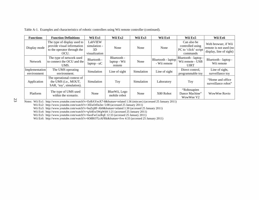
Table A-1. Examples and characteristics of robotic controllers using Wii remote controller (continued).
Functions Function Definitions Wii Ex1 Wii Ex2 Wii Ex3 Wii Ex4 Wii Ex5 Wii Ex6
Display mode
The type of display used to provide visual information to the operator through the
OCU.
LabVIEW simulation -
3D visualization
None None None
Can also be controlled using
PC to ‘click’ script commands
Web browser, if Wii remote is not used (no display, line of sight)
Network The type of network used
to connect the OCU and the UMS.
Bluetooth - laptop - uC
Bluetooth - laptop - Wii
remote None
Bluetooth - laptop - Wii remote
Bluetooth - laptop -Wii remote - USB
UIRT
Bluetooth - laptop - Wii remote
Implementation environment
The UMS operating environment.
Simulation Line of sight Simulation Line of sight Direct control,
programmable toyLine of sight,
surveillance toy
Application The operational context of
the UMS (i.e., MOUT, SAR, ‘toy’, simulation).
Simulation Toy Simulation Laboratory Toy “Home and office surveillance robot”
Platform The type of UMS used
within the scenario. None
BlueWii, Lego mobile robot
None X80 Robot “Robosapien
Dance Machine” WowWee V2
WowWee Rovio
Notes: Wii Ex1: http://www.youtube.com/watch?v=EeBAYeoX7-8&feature=related 1:36 (min:sec) (accessed 25 January 2011) Wii Ex2: http://www.youtube.com/watch?v=3fZuOrDa3ec 5:08 (accessed 25 January 2011) Wii Ex3: http://www.youtube.com/watch?v=buZzj8F-Ab0&feature=related 1:30 (accessed 25 January 2011) Wii Ex4: http://www.youtube.com/watch?v=qA4Ew5WgWd4 1:21 (accessed 25 January 2011) Wii Ex5: http://www.youtube.com/watch?v=6wsFwCnzRqE 12:33 (accessed 25 January 2011) Wii Ex6: http://www.youtube.com/watch?v=KMRO7LtAFRk&feature=fvw 4:33 (accessed 25 January 2011)

24
Table A-2. Examples and characteristics of robotic controllers using other mobile devices.
Functions Function Definitions iPhone Ex1 iPhone Ex2 PSP Ex1 PDA Ex1
OCU
Operator Control Unit - The OCU within this context refers to the capabilities that are incorporated in the
device to operate the UMS.
Touch screen video interface
Touch screen video interface with directional
arrows and flapper controls (up/down
arrows)
Robot video feed display, directional
arrows
Touch screen video interface
Navigation The input modality for UMS direction and/or
orientation.
Touch screen video interface, controlled by dragging a finger across the screen to move the
robot
Touch screen video interface with directional
arrows and flapper controls (up/down
arrows)
Directional arrows
Touch screen video interface, controlled by dragging a finger across the screen to move the
robot
Location Presentation of the
physical location of the UMS.
None None None None
Speed Presentation of the speed
of the UMS. None None None None
Feedback The type of feedback
provided to the operator through the OCU.
Visual - payload camera, real time
Visual - payload camera, real time
Visual - payload camera, real time
Visual - payload camera, real time
Mode of operation Team configuration
during UMS operation. none
Operator does not have to be line of sight
None None
Robot motion control The input modality for UMS motion control.
Touch screen - finger scroll
Touch screen - directional arrows
Directional arrows Touch screen - finger
scroll
Robot capability control The input modality for
UMS capability control.None
Touch screen - directional arrows for
flapper control None None
Display mode
The type of display used to provide visual
information to the operator through the
OCU.
Real time video data - there is a time delay
though Real time video data — —

25
Table A-2. Examples and characteristics of robotic controllers using other mobile devices (continued).
Functions Function Definitions iPhone Ex1 iPhone Ex2 PSP Ex1 PDA Ex1
Display mode
The type of display used to provide visual
information to the operator through the
OCU.
Real time video data - there is a time delay
though Real time video data — —
Network The type of network used to connect the OCU and
the UMS. Wireless
Wireless – PackBot’s WiFi network
— —
Implementation environment
The UMS operating environment.
Line of sight with video feedback
Line of sight not required. Same
capabilities as current PackBot OCU
— —
Application The operational context
of the UMS (i.e., MOUT, SAR, ‘toy’, simulation).
Small modular robot - surveillance
SAR - lab video — —
Platform The type of UMS used
within the scenario. WIFIbot M iRobot PackBot — —
Notes: iPhone Ex1: http://www.youtube.com/watch?v=bIGUPMY20ZE&feature=player_embedded 3:06 (accessed 25 January 2011) iPhone Ex2: http://www.youtube.com/watch?v=mkM92ateTwo 1:55 (accessed 25 January 2011) PSP Ex1: http://www.youtube.com/watch?v=H4FlGPHW-q4&feature=related 1:33 (accessed 25 January 2011) PDA Ex1: http://www.youtube.com/watch?v=S28Bsx5nsgE 0:47 (accessed 25 January 2011)

26
INTENTIONALLY LEFT BLANK.

27
List of Symbols, Abbreviations, and Acronyms
ARL U.S. Army Research Laboratory
LED light-emitting diode
OCU operator control unit
PDA personal digital assistant
PSP PlayStation Portable
UGV unmanned ground vehicle
UMS unmanned system
URL uniform resource locator

NO. OF COPIES ORGANIZATION
28
1 DEFENSE TECHNICAL (PDF INFORMATION CTR only) DTIC OCA 8725 JOHN J KINGMAN RD STE 0944 FORT BELVOIR VA 22060-6218 1 DIRECTOR US ARMY RESEARCH LAB IMNE ALC HRR 2800 POWDER MILL RD ADELPHI MD 20783-1197 1 DIRECTOR US ARMY RESEARCH LAB RDRL CIO LL 2800 POWDER MILL RD ADELPHI MD 20783-1197 1 DIRECTOR US ARMY RESEARCH LAB RDRL CIO MT 2800 POWDER MILL RD ADELPHI MD 20783-1197 1 DIRECTOR US ARMY RESEARCH LAB RDRL D 2800 POWDER MILL RD ADELPHI MD 20783-1197

NO. OF NO. OF COPIES ORGANIZATION COPIES ORGANIZATION
29
1 ARMY RSCH LABORATORY – HRED RDRL HRM A J MARTIN MYER CENTER BLDG 2700 RM 2D311 FORT MONMOUTH NJ 07703-5601 1 ARMY RSCH LABORATORY – HRED RDRL HRM C A DAVISON 320 MANSCEN LOOP STE 115 FORT LEONARD WOOD MO 65473 2 ARMY RSCH LABORATORY – HRED RDRL HRM DI T DAVIS J HANSBERGER BLDG 5400 RM C242 REDSTONE ARSENAL AL 35898-7290 1 ARMY RSCH LABORATORY – HRED RDRL HRS EA DR V J RICE BLDG 4011 RM 217 1750 GREELEY RD FORT SAM HOUSTON TX 78234-5002 1 ARMY RSCH LABORATORY – HRED RDRL HRM DG K GUNN BLDG 333 PICATINNY ARSENAL NJ 07806-5000 1 ARMY RSCH LABORATORY – HRED ARMC FIELD ELEMENT RDRL HRM CH C BURNS THIRD AVE BLDG 1467B RM 336 FORT KNOX KY 40121 1 ARMY RSCH LABORATORY – HRED AWC FIELD ELEMENT RDRL HRM DJ D DURBIN BLDG 4506 (DCD) RM 107 FORT RUCKER AL 36362-5000 1 ARMY RSCH LABORATORY – HRED RDRL HRM CK J REINHART 10125 KINGMAN RD BLDG 317 FORT BELVOIR VA 22060-5828 1 ARMY RSCH LABORATORY – HRED RDRL HRM AY M BARNES 2520 HEALY AVE STE 1172 BLDG 51005 FORT HUACHUCA AZ 85613-7069
1 ARMY RSCH LABORATORY – HRED RDRL HR MP D UNGVARSKY POPE HALL BLDG 470 BCBL 806 HARRISON DR FORT LEAVENWORTH KS 66027-2302 1 ARMY RSCH LABORATORY – HRED RDRL HRM DQ M R FLETCHER NATICK SOLDIER CTR AMSRD NSC WS E BLDG 3 RM 343 NATICK MA 01760-5020 1 ARMY RSCH LABORATORY – HRED RDRL HRM AT J CHEN 12350 RESEARCH PKWY ORLANDO FL 32826-3276 1 ARMY RSCH LABORATORY – HRED RDRL HRM AT C KORTENHAUS 12350 RESEARCH PKWY ORLANDO FL 32826 1 ARMY RSCH LABORATORY – HRED RDRL HRM AS C MANASCO SIGNAL TOWERS BLDG 29808A RM 303A FORT GORDON GA 30905-5233 1 ARMY RSCH LABORATORY – HRED RDRL HRM CU 6501 E 11 MILE RD MS 284 BLDG 200A 2ND FL RM 2104 WARREN MI 48397-5000 1 ARMY RSCH LABORATORY – HRED FIRES CTR OF EXCELLENCE FIELD ELEMENT RDRL HRM AF C HERNANDEZ 3040 NW AUSTIN RD RM 221 FORT SILL OK 73503-9043 1 ARMY RSCH LABORATORY – HRED RDRL HRM AV S MIDDLEBROOKS 91012 STATION AVE RM 348 FORT HOOD TX 76544-5073 1 ARMY RSCH LABORATORY – HRED RDRL HRM CN R SPENCER DCSFDI HF HQ USASOC BLDG E2929 FORT BRAGG NC 28310-5000

NO. OF COPIES ORGANIZATION
30
1 ARMY RSCH LABORATORY – HRED RDRL HRM DW E REDDEN BLDG 4 CL 60 FORT BENNING GA 31905-5400 1 ARMY G1 (CD DAPE MR B KNAPP only) 300 ARMY PENTAGON RM 2C489 WASHINGTON DC 20310-0300
ABERDEEN PROVING GROUND 4 DIR USARL RDRL HR L ALLENDER T LETOWSKI RDRL HRM P SAVAGE-KNEPSHIELD RDRL HRS D B AMREIN
NO. OF COPIES ORGANIZATION
31
ABERDEEN PROVING GROUND 4 DIR USARL RDRL HRS E S HILL

32
INTENTIONALLY LEFT BLANK.

![Learning Robust Control Policies for End-to-End …amini/pubs/pdf/learning-in-simulation-vista.pdfTraining and evaluating robotic controllers in simulation [5]–[7] has emerged as](https://img.dokumen.tips/doc/110x75/5f0ccd277e708231d43732fd/learning-robust-control-policies-for-end-to-end-aminipubspdflearning-in-simulation-vistapdf.jpg)


![Automating Verification of State Machines with Reactive ... · 2 Simon Foster et al. RoboChart [1,23] is a diagrammatic language for the description of robotic controllers with denotational](https://img.dokumen.tips/doc/110x75/60e39494d9393942a254d1df/automating-verification-of-state-machines-with-reactive-2-simon-foster-et-al.jpg)