Embed Size (px)
Citation preview

Using mesh-geometry relationships to transfer analysis modelsbetween CAE tools
Tierney, C., Nolan, D., Robinson, T., & Armstrong, C. (2015). Using mesh-geometry relationships to transferanalysis models between CAE tools. Engineering With Computers, 31(3), 465-481.https://doi.org/10.1007/s00366-014-0377-7
Published in:Engineering With Computers
Document Version:Peer reviewed version
Queen's University Belfast - Research Portal:Link to publication record in Queen's University Belfast Research Portal
Publisher rights Copyright 2014 Springer-Verlag London
The final publication is available at Springer via http://dx.doi.org/10.1007/s00366-014-0377-7
General rightsCopyright for the publications made accessible via the Queen's University Belfast Research Portal is retained by the author(s) and / or othercopyright owners and it is a condition of accessing these publications that users recognise and abide by the legal requirements associatedwith these rights.
Take down policyThe Research Portal is Queen's institutional repository that provides access to Queen's research output. Every effort has been made toensure that content in the Research Portal does not infringe any person's rights, or applicable UK laws. If you discover content in theResearch Portal that you believe breaches copyright or violates any law, please contact [email protected].
Download date:15. Jan. 2022

1
Using mesh-geometry relationships to transfer
analysis models between CAE tools
Christopher Tierney, Declan Nolan, Trevor Robinson and Cecil Armstrong
School of Mechanical and Aerospace Engineering, Queen’s University
Belfast, BT9 5AH [email protected]
Abstract. Integrating analysis and design models is a complex task due to
differences between the models and the architectures of the toolsets used to
create them. This complexity is increased with the use of many different
tools for specific tasks during an analysis process. In this work various de-
sign and analysis models are linked throughout the design lifecycle, allow-
ing them to be moved between packages in a way not currently available.
Three technologies named Cellular Modeling, Virtual Topology and
Equivalencing are combined to demonstrate how different finite element
meshes generated on abstract analysis geometries can be linked to their
original geometry. Cellular models allow interfaces between adjacent cells
to be extracted and exploited to transfer analysis attributes such as mesh
associativity or boundary conditions between equivalent model representa-
tions. Virtual Topology descriptions used for geometry clean-up operations
are explicitly stored so they can be reused by downstream applications. Es-
tablishing the equivalence relationships between models enables analysts
to utilize multiple packages for specialist tasks without worrying about
compatibility issues or substantial rework.
Key Words. Mesh-geometry ownership, CAD / CAE integration, Cellular Model-
ing, Virtual Topology, Equivalence
1 Introduction
The introduction of Computer Aided Design (CAD) and Computer Aided
Engineering (CAE) tools has had a major impact on the Product Develop-
ment Process. Designs can be developed and tested in the virtual environ-
ment, reducing the need for expensive prototypes. Computational analysis
methods like finite element analysis (FEA) have progressed from valida-
tion and failure verification tools to design and concept verification tools,
resulting in them being employed earlier in design cycles where analysis
results drive the design process [15]. Consequently, the capabilities of
modern analysis tools are rapidly increasing, along with the complexity of

2
the analyses being undertaken. This has led to more detailed analyses be-
ing performed at earlier stages of design processes. Aerospace companies
undertake multi-level, multi-disciplinary analyses of components through-
out the design process. The multi-disciplinary analyses allow for a more
accurate assessment of the overall behavior of a system, but leads to a sig-
nificant burden when preparing the different analysis models.
Fig. 1. Common analysis process using current methods
In many analysis cycles there are numerous pre-processing steps required
to enable geometric domains to be more adequately meshed, Fig. 1. Pre-
processing steps may include model simplifications where manufacturing
or aesthetic design details which are assumed to have no simulation signif-
icance are removed [18]. The pre-processing steps tend to vary depending
on analysis requirements and the stage of the design process, e.g. details
that are significant for a stress analysis may be irrelevant for a modal anal-
ysis. In other circumstances different geometric decompositions may be
required for analyzing different load cases for a product so that high stress
areas can be accurately represented. With multiple decompositions of the
same CAD model required for different analysis tasks, it is essential that
bi-directional links exist between equivalent models [1]. These links are
necessary to ensure that results can be exchanged between different analy-
sis models at varying levels of fidelity. This is especially true for coupled
multi-disciplinary analyses where the output from one simulation acts as
the input to another e.g. thermo-mechanical analysis.
In reality industrial companies utilize numerous specialist tools for
analysis activities. One such example is aero-elastic analyses where dis-
tinct solvers are often utilized in order to achieve as accurate a solution as
possible. The tools employed depend heavily on the task being performed,
the type of physics involved, the stage of the design process and the com-
plexity of the component or assembly to be analyzed [5]. Early in a design
process it may be appropriate to use an automatically generated unstruc-
tured tetrahedral (tet) mesh to gain an initial insight into the performance
of the product. However, later in the design process it may be desirable to
use multiple different analysis packages with specific hexahedral (hex)
meshing capabilities. This can result in multiple analysis models existing
for a given component with no robust link between them and no link back

3
to the original design geometry. Furthermore, the fact these equivalent
analysis representations are often generated by different people, and within
distinct analysis pre-processing packages, adds significantly to the com-
plexity of the CAD/CAE integration problem.
Solving computational analysis problems requires a fit-for-purpose fi-
nite element mesh to be generated on the abstract analysis geometry, along
with any applicable analysis attributes such as boundary conditions, load-
ing and material properties. The application of boundary conditions for
large assemblies like whole engine thermo-mechanical models can be a te-
dious and time consuming task due to the vast number of physical interac-
tions present in the assembly models. This process is frequently complicat-
ed by the necessity to generate different abstract analysis models for both
thermal and structural domains. For example, a thermal analysis may be
carried out using a tet mesh automatically generated on an abstract analysis
model. However, the abstract analysis model may need to be simplified
further in order to obtain a suitable hex mesh for a large-deformation struc-
tural analysis. Without a robust method to transfer analysis information be-
tween packages the application of boundary conditions often has to be re-
peated many times during the lifecycle of a design. It is shown in this work
that the ability to link meshes from various analysis geometries back to the
original CAD model (and by extension each other) reduces rework in
terms of setting up the analysis model, even when they are generated with-
in different analysis packages.
Mesh-geometry ownership is the relationship between individual mesh
entities and their parent B-Rep entity. During mesh generation modern
packages automatically impose mesh-geometry ownership, allowing ap-
plied boundary conditions to be transferred to the corresponding nodes and
elements of the mesh [2]. This process is more convenient than applying
boundary conditions to individual mesh entities, which can be cumber-
some for even the simplest of models. For the purposes of assembling the
finite element matrices, boundary conditions on the B-Rep entities are in-
ternally converted to equivalent nodal ‘loads’ or imposed ‘displacements’.
Therefore, CAD model updates or mesh modifications can be made with-
out having to reapply loads. Using current tools it is not always the case
that mesh-geometry ownership can be successfully transferred from the
package in which it was created to a different downstream package, espe-
cially when the models are of varying levels of abstraction or fidelity. This
makes repetitive manual operations essential in order to successfully recre-
ate the mesh-geometry ownership at other stages in the design process,
which is highly undesirable for situations such as mesh adaption where
frequent global and/or local mesh refinements may be performed. There-
fore, robust links between equivalent model representations are required.
In this work, recording the equivalent relationships between design and
analysis models enables finite element meshes created on abstract analysis

4
geometries to be fully associated with the original design model, regardless
of the packages within which they were created. This enables analysis at-
tributes like element properties and boundary conditions to be transferred
between different packages and analysis models at various levels of fideli-
ty, without compromising the model integrity. This gives an analyst the
freedom to select the desired tools for specific aspects of the analysis pro-
cess without having to worry about compatibility issues or any substantial
rework involved in transferring and rebuilding analysis models. Releasing
the analyst from time consuming manual rework allows more considera-
tion to be given to the analysis being performed.
2 Three technologies for linking design and analysis models
This work describes how three technologies named Cellular Modeling,
Virtual Topology and Equivalencing are used to manage and manipulate
the topology of geometric design and analysis models, enabling them to be
linked, independent of any underlying CAD or CAE package [19]. These
technologies are not new by themselves, but their combination for
CAD/CAE integration in the manner described is novel. In this section a
brief description of the three technologies is provided.
2.1. Cellular Modeling
Cellular representations are defined as non-manifold representations of
both positive (solid) and negative (void) regions [3]. In manifold represen-
tations any point on the boundary of a solid region has a neighborhood
homeomorphic to a 2-dimensional disk [20]. Geometric representations
that are not manifold are referred to as non-manifold. An example of a
non-manifold condition is a face which bounds two distinct volume cells.
The face and its bounding entities are shared between the two volume
cells. Using cellular models means these interfaces can be identified and
utilized to define boundary conditions between adjacent components. Fig.
2 (b) shows the interfaces in a non-manifold cellular representation.
Cellular representations have been used in assembly mesh generation,
where non-manifold topological entities between interacting components
provide suitable interfaces for conformal meshing [21]. Conformal mesh-
ing is considered the most accurate form of connectivity between volume
cells with compatible element types and is often used instead of contact el-
ements or constraint equations. At non-manifold interfaces shared faces
are meshed before the volume mesh is created, resulting in shared nodes at
the common interface. In other work Sypkens-Smit and Bronsvoort [17]

5
used cellular modeling representations for remeshing feature models. Cells
in the cellular model are related to their parent features so they can be
tracked after model updates, allowing boundaries to be compared so that
local remeshing can be efficiently achieved. Lee et al. [6] introduced a
method for CAD model simplification using cellular representations. In
this approach each feature in a design model is explicitly defined as a vol-
umetric cell in the global cellular model. Cells below a certain threshold
volume can be suppressed to achieve the desired abstracted model for dif-
ferent applications.
Fig. 2 Non-manifold cellular representations: (a) Casing component partitioned in-
to thin-sheet and long-slender regions, (b) Highlighted interfaces between interact-
ing cells
In this work a region in a non-manifold representation is referred to as a
cell. Cells can have any manifold dimension, i.e. volumes, faces, edges and
vertices are all considered as regions of space bounded by other cells. Cel-
lular models represent the entire design space subdivided into regions with
specific analysis significance. Fig. 2 (a) shows a model that has been parti-
tioned into sub-regions to support downstream meshing, more details of
which can be found in [8, 13]. The analysis significance of each cell can be
used to automatically determine how to manage the interfaces between ad-
jacent cells. For instance, mesh connections, such as multi-point con-
straints (MPCs) or rigid links, can be used at interfaces between cells that
are meshed with incompatible mesh types. Handling the interfaces be-
tween components offers the chance to automate many manual pre-
processing tasks, particularly when used with the analyst’s ‘Simulation In-
tent’ as described in [10].
Assigning attributes to volume cells enables lower level topological at-
tributes to be automatically managed and used to build relationships be-
tween equivalent models. Every cell in the cellular decomposition contains
information specifying its origin in relation to the design model. The origin
of a cell can be used along with the interfaces between interacting cells to
link design and analysis models at various levels of fidelity. In situations
where multiple cells have the same originating cell it is possible to use Vir-
tual Topology to create associations between the different cells.

6
2.2. Virtual Topology
Virtual Topology was introduced by Sheffer et al. [14] as a technique for
preparing CAD models for analysis purposes. It allows simplifications to
be made on a model without having to directly modify the geometry,
which may introduce even more changes from the original model. Virtual
Topology operations use real topological entities called Hosts in order to
create virtual entities. Virtual superset entities represent the combination of
multiple adjacent entities of the same manifold dimension, while virtual
subset entities represent a partial section of another entity. Parasite entities
are used to split a higher dimensional topological entity into several subset
entities e.g. a parasite face is used to partition a volume to simplify the ge-
ometric model for meshing applications. These virtual entities are generat-
ed using the virtual topology operators described below.
Fig. 3. Virtual Topology geometry clean-up used to collapse a face to an edge. (a)
Model with small blend feature, (b) Superset face, (c) Coarse mesh on original
model, (d) Subset faces, (e) Coarse mesh on abstract analysis model
The two main Virtual Topology operators utilized in this work are the
merge and split operators. Using the merge operator adjacent entities of the
same manifold dimension are merged into a single virtual superset entity
by ignoring the common boundary between them, for example the dashed
edges and highlighted vertices in Fig.3 (b). The split operator is used to
partition a single host entity into virtual subset entities. The host entity can
be a real or virtual topological entity, such as the superset face that has
been partitioned in Fig. 3 (d). Virtual parasite entities are used to partition

7
the boundary of the host entity to create the virtual subsets. Sheffer [14]
uses the construction operator to generate virtual parasite entities by defin-
ing their bounding entities, i.e. a parasite edge is created by defining its
bounding vertices.
One application of Virtual Topology is geometry clean-up for mesh
generation, as shown in Fig. 3. Small features like blend faces, highlighted
grey in Fig. 3 (a). Small features like blend or sliver faces provide prob-
lems to mesh generation algorithms as nodes are usually distributed along
all bounding entities in a model. When faces are small in comparison to
the target element size, poorly shaped elements are created, Fig. 3 (c),
which can have an adverse effect on the accuracy and efficiency of an
analysis. Actual abstraction of the blend feature may vary depending on
the application or the preference of the analyst. One method is to merge
the blend face with its adjacent faces and to partition the resulting virtual
superset face, a process which is illustrated in Fig. 3 (b) and (d). These
Virtual Topology procedures effectively collapse the blend face to an edge
and are used to modify the topological connectivity of the blend feature, so
as to achieve a mesh coarser than the blend size, Fig. 3 (e). Even though
the topology of the face has been altered, its geometric attributes remain
intact. This is beneficial in situations where a feature needs to be retained
from an analysis perspective, but its topology can still be modified to facil-
itate the creation of block topologies for semi-structured hex meshing.
Many analysis or mesh generation packages currently have Virtual To-
pology capabilities. Some packages make these Virtual Topology deci-
sions internally without reporting the details to the analyst, making it diffi-
cult for the analyst to determine where it has been used and therefore to
interrogate or modify the Virtual Topology. Once Virtual Topology has
been used to simplify a model for meshing, certain packages do not allow
the simplified geometry to be exported. These issues make it difficult to
reuse the Virtual Topology generated and counteract the desired automa-
tion of the analysis process. Virtual Topology operations are pre-
processing steps taken to produce fit-for-purpose analysis geometry and
should be robustly stored as such.
The ability to interrogate the Virtual Topology enables the Virtual To-
pology relationships (the linkages between host entities and virtual enti-
ties) to be stored and ultimately accessed by other downstream applica-
tions. Section 3 describes a general procedure for extracting the VT in
situations where it cannot be directly extracted from the CAE solution it
was generated within. Identifying and storing Virtual Topology decisions
within an external data structure enables the relationships to be accessed
and utilized by other CAE packages regardless of the Virtual Topology ca-
pabilities of the downstream client, i.e. once Virtual Topology relation-
ships have been identified and stored the Virtual Topology does not need
to be regenerated in another package. In addition, these relationships ena-

8
ble multiple analysis decompositions to be linked to each other by using
the appropriate non-manifold interfaces to identify Virtual Topology rela-
tionships. Once analysis geometries have been linked to the original geom-
etry, meshes generated on the abstract analysis models can be linked back
to the original model and, by extension, to each other. In this work the
manufacturing detailed design model is referred to as the original model.
Having multiple meshes associated with the same geometry is a significant
advantage of this approach, especially where it may be necessary to trans-
fer results between the distinct meshes. Whilst the actual mapping of re-
sults is not covered in this work the links between the respective meshes
are identified and stored in an accessible manner.
2.3. Equivalencing
Different analysis models and therefore different meshes are required for
different applications during the design process. The analysis models can
differ due to the stage of the analysis or even the type of analysis being
performed. Early in design processes simpler analysis models representing
fewer details and with fewer degrees of freedom may be utilized as ap-
proximate results are often acceptable, provided they are returned quickly.
Analysis complexity normally increases as the design evolves. Different
meshes are required to solve different physics problems and to get more
detailed results.
In this work it is considered that as a mesh is a representation of a do-
main, all meshes of that domain can be considered equivalent to it and
each other. The representative example, in Fig. 4, shows various analysis
models that are considered equivalent as they represent the same compo-
nent. For example, early in the design process a pinion shaft may be repre-
sented using two 1-dimensional beam elements with different cross-
sectional properties, Fig. 4 (a). A coarse tet mesh may be required for a
modal analysis, Fig. 4 (b) and a structured hex mesh may be required at a
later stage for an impact analysis, Fig. 4 (c). During detailed design stages
a hybrid mesh including tooth geometry may be necessary for a stress
analysis, Fig. 4 (d). While these different representations are adequate for
their specific purpose, in this work equivalence relationships are deter-
mined between equivalent cells in the model. For example, the pinion body
is represented as a beam element in Fig. 4 (a), a tet meshed or hex meshed
cylinder cell in Fig. 4 (b) and (c) and a tet mesh of a detailed geometry in-
cluding gear teeth in Fig. 4 (d). The end vertices of the beam elements are
considered equivalent to planar faces of the pinion head in other represen-
tations. Similarly, relationships between the simple gear and detailed gear
cells can be determined by exploiting the links to the dimensionally re-
duced representation. For example, once the end vertices of the 1D ideali-
zation representing the pinion head are identified as equivalent to the pla-

9
nar faces of the pinion head in the more detailed representations, all resid-
ual faces bounding the pinion head are considered equivalent to the wire
edge of the beam element. The relationships between the collection of
tooth faces and the cylindrical (smoothed) face of the pinion head are de-
termined by exploiting the links between the detailed geometries and the
equivalent 1D idealization. In situations where equivalent relationships are
not available through links to an idealized representation it is possible to
utilize the non-manifold combination of the cells, where non-manifold fac-
es represent interactions between cells, to identify the equivalence depend-
encies. Virtual Topology is used to manage the dependencies between
edges faces or volumes cells which have been merged, or partitioned, for
analysis purposes without modifying the geometric representation. This is
opposed to Equivalencing, which is used to manage the dependencies be-
tween distinct geometric or analysis models which exist due to the design
evolution, or due to modifications such as feature suppression or dimen-
sional reduction.
Fig. 4. A simple pinion shaft with different meshes applied for specific tasks dur-
ing a design process: (a) Beam elements with different cross-sectional properties,
(b) Linear tet mesh, (c) Structured hex mesh, (d) Hybrid mesh.
By establishing the equivalences between individual analysis geometries
and the original model it is possible to transfer analysis attributes and re-
sults between all models generated for that domain. The actual transfer of
analysis attributes, such as loading, is not covered in this work and would
require the transformation of boundary conditions between equivalent rep-
resentations, i.e. the dimensional reduction of boundary conditions as de-
scribed by Donaghy [4]. The extent of the transformation is dictated by the
shape difference between the equivalent representations.

10
3 Robust mesh transfer process
In many CAE tools boundary conditions are applied to topological entities
in the simplified geometric model, Fig. 1. If analysis and design models
are not connected then boundary conditions need to be reapplied for each
subsequent analysis model. This could be extremely costly where a design
is updated frequently. Using the approach described here boundary condi-
tions can be defined on the original design geometry without having to
worry about any downstream idealizations that may occur, Fig. 5.
Fig. 5. Analysis process using the master database to link various representations.
Once fit-for-purpose meshes have been generated, the simplified geometric
model is no longer required to achieve the analysis solution. Storing
equivalent links between the simplified and original models allows mesh-
geometry ownership to be transferred between the models. Therefore,
boundary conditions assigned to the original model can be automatically
transferred to the mesh of the idealized model before it is solved. This re-
sults in integrated design and analysis capabilities that can have major
benefits in large collaborative projects with many distributed partners. Dif-
ferent departments and sub-contractors are assigned specific tasks within
the analysis process. Each partner may prefer to use their toolsets of choice
without having to consider how this may affect downstream collaboration,
or without sharing any information about how the models were generated
to protect intellectual property. Example tasks which may be integrated in-
clude model simplification, meshing, assignment of boundary conditions
etc. Integrating the models produced and required by the different analysis
tools ensures tighter integration of the entire design and analysis process.
In order to transfer various finite element attributes between different
models, residing in different packages, it is essential that the various mod-
els are robustly linked [7, 16]. The ability to relate different meshes back
to the same design model provides tighter integration between the disci-
plines. In order to link these models a simple data structure has been de-
veloped which is independent of any underlying CAD or CAE package.
The data structure has been implemented in the form of a relational data-

11
base whose entity relation diagram is detailed in Fig. 6, [19]. Its purpose is
not to replace existing data structures used to represent models in CAD
and CAE systems, rather it is used to store the non-manifold topology of
the cellular model for the product being designed, and also the different
approximations and analysis models that represent it. All equivalent de-
compositions of the product are stored regardless of their dimension or the
tools used to create them. The database acts as a master model for linking
these equivalent representations. The advantage of using a non-manifold
model is that non-manifold interfaces are used, along with Virtual Topolo-
gy and equivalence information to integrate the different models. A com-
plete description of the data structure and its use for analysis applications
is available in [19].
Fig. 6. Database entity-relation diagram.
Once the analysis geometry has been created its non-manifold topology
can be stored in the data structure, Fig. 6. The topology is stored inde-
pendently of the packages used to create the model and in a generic format
that makes it accessible by any CAD or CAE package. The main topologi-
cal entities (vertices, edges, faces and volumes) are represented in the Enti-
ty relation using their unique Identifier, which is a point within the bound-
ary of the entity. The Identifier enables robust identification of entities
between various packages. This is in comparison to naming attributes that
may go missing, change or cannot be applied to a topological entity. The
topological connectivity of a model is stored in the Topology relation of
the data structure, where each row defines a cell, one of its bounding enti-
ties and the relative orientation of the two (e.g. whether a surface normal
points into or out of a body). Bi-directional links exist between the topolo-
gy in the data structure and different design and analysis models using the
Virtual Topology relation and an Identifier. This is stored as a String in the
entity table but actually defines a point contained within boundary of the
entity.
The topology of various decompositions of the same component can be
stored concurrently in the data structure, along with any mesh-geometry
ownership relationships. A simple example is introduced Fig. 7 to describe
the relationships between equivalent decompositions. By identifying the

12
links between the original, Fig. 7 (a), and simplified geometries, Fig. 7 (b),
it is possible to link their respective meshes. The Virtual Topology relation
of Fig. 6 is used to store the link between the equivalent models. Superset
edge ‘ve1’ is created by merging edges ‘e1’, ‘e2’ and ‘e3’, which are
stored as its host entities, Fig. 7 (e). Virtual superset face ‘vf1’ is stored in
the same manner for faces ‘f1’, ‘f2’ and ‘f3’. Linking the original and vir-
tual models enables their meshes to be linked by manipulating their mesh-
geometry relationships. Therefore, results may be transferred between the
different models. Consider the original geometry in Fig. 7 (a) and where a
mesh for a thermal analysis has been created to calculate the temperatures
on each face, Fig. 7 (c). A fine mesh can be used for a thermal analysis as
nodes have only one degree of freedom and the analysis is relatively inex-
pensive. Once temperatures have been calculated Virtual Topology rela-
tionships are used to link them to the simplified model in Fig. 7 (b). To
achieve this, the collection of element faces of the thermal analysis mesh
are related back to their parent topological faces (‘f1’, ‘f2’ and ‘f3’). These
topological faces are linked to the virtual face in the simplified model and
by extension to the coarse mesh, Fig. 7 (d), applied to the virtual face.
Once the links have been determined temperature values can be mapped
and interpolated between source and target meshes in order to execute a
structural analysis. The interpolation between meshes is not explored in
this paper. The important point is that the meshes used for different anal-
yses can be linked using the Virtual Topology for the two equivalent ge-
ometries.
Fig. 7. Linking different decompositions: (a) Original geometry, (b) Simplified
geometry, (c) Fine mesh on original geometry, (d) Coarse mesh on simplified ge-
ometry, (e) Virtual Topology relationships.
In this work the goal is to establish and store relationships between the
topological entities in equivalent design and analysis representations. Vir-
tual Topology is used to store the relationships between different represen-
tations when a one-to-one correspondence does not exist between related
entities. These cells have to be defined as supersets or subsets of different
cells. Equivalent relationships are stored when the same region of the de-
sign space is represented at different levels of fidelity. Once these relation-
Entity Host Entity
ve1 e1
ve1 e2
ve1 e3
vf1 f1
vf1 f2
vf1 f3
(a)
(e)
(d) (c)
(b)

13
ships have been defined, analysis attributes can be transferred between
models at various levels of fidelity.
4 Identifying Virtual Topology relationships
Automated Virtual Topology tools available in commercial CAE packages
can be used for geometry clean-up. They operate by identifying small fea-
tures that may hinder the mesh generation process and merge them with
adjacent larger features in the model, without altering the actual CAD ge-
ometry. Entities are merged by ignoring their common bounding entities,
i.e. common edges are ignored to merge adjacent faces. To enable Virtual
Topology operations to be reused in other downstream applications it is
necessary to establish relationships between virtual entities and their host
entities so they can be stored in the database. Since many CAE tools do not
report the details of Virtual Topology operations, it is necessary to identify
the entities in the original model to which it has been applied, (i.e. the host
entities). The two types of virtual entities to be identified are superset and
subset entities, where superset and subset entities are created by merge and
split operations respectively. The relevant Virtual Topology relationships
can be extracted by finding either the entities that have been ignored,
where a superset has been created, or the new entities (parasites) that have
been introduced, where subset entities have been created.
4.1. Virtual Topology for geometry clean-up
Virtual merge operations are predominantly used during geometry clean-
up operations to remove troublesome features like sliver faces. Virtual
subsets may be required to partition an entity for load application, mesh
control, or as a precursor to the creation of a superset entity, where it may
be necessary to merge subset entities. Once created, the identification of
both virtual subsets and superset relationships will be described in this sec-
tion.
Fig. 8 shows a simple example where both merge and split operators are
used in order to generate an appropriate abstract analysis model. The
smaller blend in the model may be ignored as it is below the target element
size or to simplify the domain prior to volume decomposition for meshing
(section 4.2). Topology comparisons between the original model and the
abstract analysis model have been used to identify the virtual topology re-
lationships generated as a result of merge or split operations. Virtual subset
relationships are identified by finding entities that exist in the abstract
model but not in the original model. Conversely, entities that do not exist
in the abstract model as opposed to the original model have been used to
14
link virtual superset entities to their host entities. Having already stored the
topology of the original model in the data structure it is relatively straight-
forward to identify topological differences between the models. The ability
to maintain multiple representations at once in the data structure provides
the functionality to use virtual entities as the input to further virtual opera-
tions.
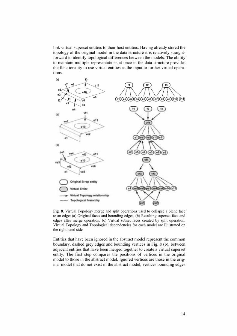
Fig. 8. Virtual Topology merge and split operations used to collapse a blend face
to an edge: (a) Original faces and bounding edges, (b) Resulting superset face and
edges after merge operation, (c) Virtual subset faces created by split operation.
Virtual Topology and Topological dependencies for each model are illustrated on
the right hand side.
Entities that have been ignored in the abstract model represent the common
boundary, dashed grey edges and bounding vertices in Fig. 8 (b), between
adjacent entities that have been merged together to create a virtual superset
entity. The first step compares the positions of vertices in the original
model to those in the abstract model. Ignored vertices are those in the orig-
inal model that do not exist in the abstract model, vertices bounding edges

15
‘e4’ and ‘e7’ in Fig. 8 (a). Once the ignored vertices have been identified
their bounded edges are returned by interrogating the topological connec-
tivity which has previously been stored in the data structure. Connected
pairs of bounded edges are grouped together to ensure the correct relation-
ship is defined between the virtual superset and all host edges, Fig. 8 (b)
where edge ‘ve1’ is the superset of host edges ‘e2’, ‘e5’ and ‘e8’. These
host edges have been merged together by removing their common bounda-
ries to create the virtual superset edge. The topology of the superset edge is
automatically created in the data structure by finding the unique bounding
entities of the host entities, i.e. the unshared bounding entities. In the same
manner the relationship between any superset faces and their underlying
host faces have been determined. Once all vertices in the abstract model
have been identified, the topological connectivity in the database is used to
identify any edges. Ignored edges can then be identified and their bounded
faces in the original model automatically returned from the data structure.
Therefore, the new superset face is automatically linked to its host faces
and the relationship stored in the Virtual Topology relation. For example,
virtual superset face ‘vf1’ in Fig. 8 (b) is the union of faces ‘f1’, ‘f2’ and
‘f3’ in the original model, Fig. 8 (a). The topology of the virtual superset
entity is stored in the Topology relation of the data structure. It is seen in
Fig. 8 (b) that superset face ‘vf1’ is bounded by original edge ‘e1’, ‘e10’
and ‘e11’ along with virtual edges ‘ve1’ and ‘ve2’. The topological adja-
cency information is automatically updated for all entities bounded by vir-
tual entities.
After identifying virtual supersets relationships it is possible to identify
virtual subsets and their single host entity. Entities present in the abstract
model but not the original model are classified as parasite splitting entities.
Topological entities that are bounded by these parasite entities represent
the virtual subset entities that have been created due to a split operation.
For example, the black highlighted edge in Fig. 8 (c) is identified as a par-
asite edge. It is visible from the Virtual Topology relationships in Fig. 8 (c)
that parasite edge ‘pe1’ is not stored in the Virtual Topology relation but is
easily identified as the common boundary between virtual subset faces.
The bounded faces of this parasite edge are categorized as virtual subset
faces, ‘vf2’ and ‘vf3’ in Fig. 8 (c). The link between the subset faces and
their host face, which has been partitioned by the parasite edge, is estab-
lished by finding edges which are not shared by any of the subset faces, the
‘uncommon’ edges of the subset faces. The existing topology in the data
structure is interrogated to find the host face bounded by these uncommon
edges. In this case the host face is the superset face ‘vf1’. The Virtual To-
pology dependencies in Fig. 8 (c) show that virtual entities can be refer-
enced as by new virtual entities, i.e. superset face ‘vf1’ is partitioned into
virtual subsets ‘vf2’ and ‘vf3’, while virtual superset edge ‘ve1’ is split to
form subset edges ‘ve3’ and ‘ve4’. Uncommon edges that have been used

16
in previous merge operations are replaced by the virtual superset edge, al-
lowing the correct face to be identified using the topological interrogations
described.
Virtual Topology relationships are stored in the data structure along
with the topology of the virtual entities. Storing these relationships in the
data structure creates the links between the original and abstract models
and enables them to be reused by downstream applications. Therefore,
once a mesh has been generated it can be linked to a different model in a
different package without having to recreate any virtual entities. This is a
major benefit of storing the Virtual Topology in an accessible manner,
4.2. Virtual Topology for linking equivalent geometries
Defeaturing, dimensional reduction and decomposition tools [8, 9, and 18]
are commonly used to create idealized analysis models which are less
computationally expensive. There are occasions where a model may be de-
composed or partitioned into idealized sub-regions in order to meet the
specific meshing requirements of an analyst. A requirement for many
analyses is the creation of a mesh comprised of only hexahedral elements
as they are more computational efficient due to their structured layout, i.e.
hex elements are desirable for highly non-linear transient events as they al-
low larger time steps for the explicit solver. Robust automated hex mesh
generation is still a largely unsolved problem. Geometry decomposition
methods are used to create hex meshable sub-regions.
Fig. 9. Decomposition of a simple component into hex meshable sub-regions: (a)
Original component; (b) Decomposed model with parasite face highlighted; (c)
Hex meshed component.
An example model is shown in Fig. 9 (a) where the simple component
cannot be automatically hex meshed by many commercial CAE packages.
Some CAE packages are able to automatically subdivide a model such as
this into hex meshable sub-regions, Fig. 9 (b), which can then be automati-
cally hex meshed, Fig. 9 (c), in that or a different package. The model in
Fig. 9 (b) has the same geometry clean-up operations applied to the fillet
as described in the previous section. The hex mesh is generated for the de-
composed cells by creating a quad mesh on the appropriate source face and
17
sweeping it through the volume, as the wall faces facilitate mapped mesh-
ing. This effectively simplifies the hex meshing problem into the 2D do-
main for sweepable regions.
With the objective of relating the mesh generated on the simplified ge-
ometric model to the original model, it is necessary to establish the correct
equivalences between the models. Relationships between host entities in
the original model are defined as the union between all subset entities in
the decomposed model. This process is the same as described for the sub-
set entities in the previous section, where parasite entities are identified in
the sub-divided model. The manifold dimension of parasite entities is one
less than the entity they partition, i.e. vertices are used to split edges, edges
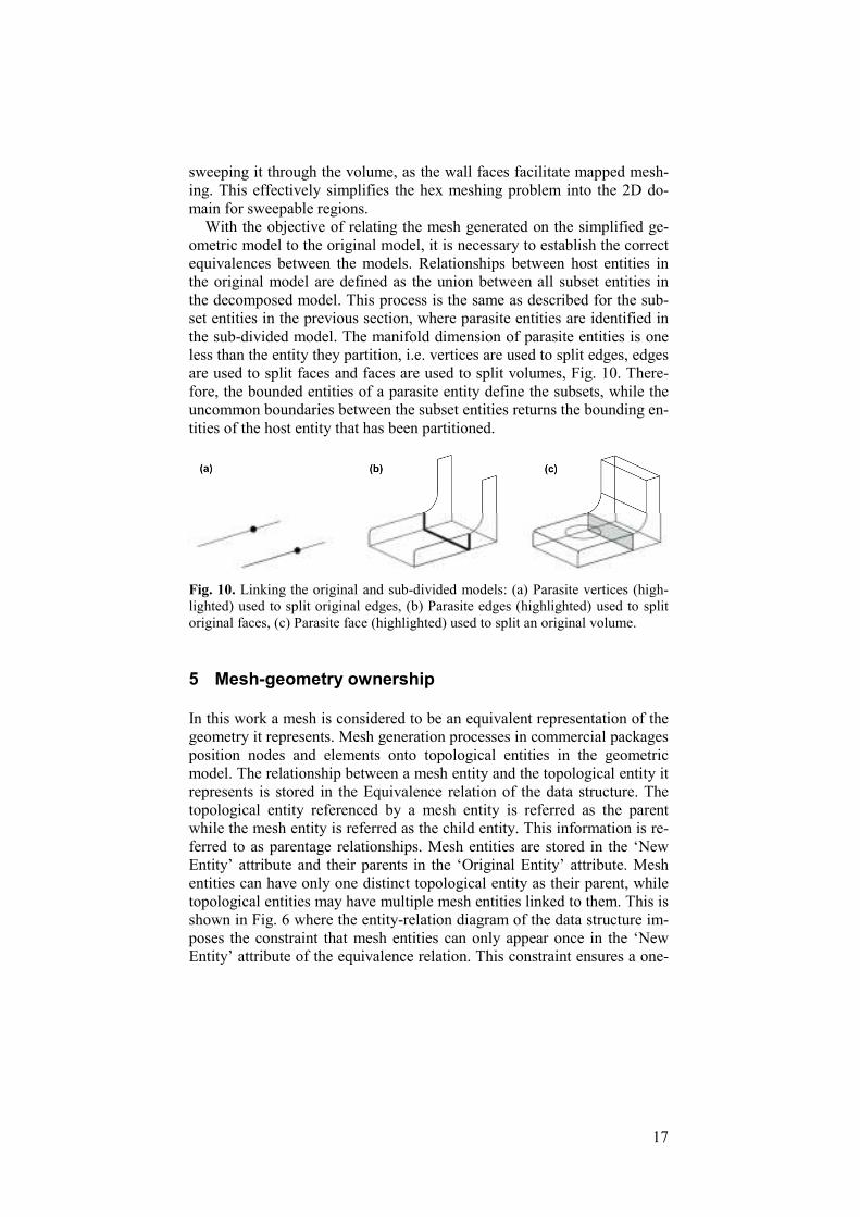
are used to split faces and faces are used to split volumes, Fig. 10. There-
fore, the bounded entities of a parasite entity define the subsets, while the
uncommon boundaries between the subset entities returns the bounding en-
tities of the host entity that has been partitioned.
Fig. 10. Linking the original and sub-divided models: (a) Parasite vertices (high-
lighted) used to split original edges, (b) Parasite edges (highlighted) used to split
original faces, (c) Parasite face (highlighted) used to split an original volume.
5 Mesh-geometry ownership
In this work a mesh is considered to be an equivalent representation of the
geometry it represents. Mesh generation processes in commercial packages
position nodes and elements onto topological entities in the geometric
model. The relationship between a mesh entity and the topological entity it
represents is stored in the Equivalence relation of the data structure. The
topological entity referenced by a mesh entity is referred as the parent
while the mesh entity is referred as the child entity. This information is re-
ferred to as parentage relationships. Mesh entities are stored in the ‘New
Entity’ attribute and their parents in the ‘Original Entity’ attribute. Mesh
entities can have only one distinct topological entity as their parent, while
topological entities may have multiple mesh entities linked to them. This is
shown in Fig. 6 where the entity-relation diagram of the data structure im-
poses the constraint that mesh entities can only appear once in the ‘New
Entity’ attribute of the equivalence relation. This constraint ensures a one-

18
to-one relationship is maintained between the mesh entity and its parent
topological entity. However, topological entities can appear many times in
the ‘Original Entity’ attribute as they can have multiple child entities.
These relationships are used to successfully transfer a mesh between mod-
els at various levels of fidelity.
5.1. Assigning mesh parentage relationships
Mesh entities include nodes, element edges, element faces and elements.
Different relationships may exist between mesh entities and their parent
topological entities. Nodes may have B-Rep vertices, edges, faces or vol-
umes as their distinct parent entity. Element edges and faces can have B-
Rep edges and faces as their respective parents if they lie on topological
boundaries. Elements have B-Rep parent entities equivalent to their di-
mensionality. For example, solid elements will have B-Rep volume cells
as their parent while shell elements will have B-Rep faces as their parent
entity.
Storing relationships between all mesh entities and their parent B-Rep
entities would introduce redundant relationships that would complicate the
transfer process. For example, element edges and faces are not equivalent
to topological edges and faces if they lie inside the boundary of a region,
which would require constant manipulation between equivalent relation-
ships. Loads and boundary conditions, such as pressure loads, are assigned
either directly as nodal values or to element faces or edges. The choice of
method is dependent on the analysis package. Therefore, parentage infor-
mation may, or may not, be required for certain mesh entities depending
on the package. However, it is certain for all packages that loads and
boundary conditions are ultimately represented on nodes and elements of
the finite element mesh before an analysis is executed [11]. Due to these
issues it has been decided to store parentage information for only node and
element mesh entities. If certain packages require the use of element edges
and faces for boundary condition application they can be derived from the
element connectivity and equivalence relationships, which are readily
available from the mesh file and the data structure. Correspondence is re-
tained between mesh entities in the data structure and the mesh file by uti-
lizing the same node and element numbers within each format.
Each B-Rep topological entity in the model is queried to find its mesh
child nodes. To ensure each node has only one distinct parent only nodes
that do not lie on the bounding entities of a B-Rep entity acquire that entity
as their parent. The correct nodal parentage relationships are formed using
a bottom-up approach, shown in Fig. 11. Topological entities with the
smallest manifold dimension are addressed first for the example where a
hex mesh is generated on the cuboid, Fig. 11 (b). Firstly, all vertices in the
model are interrogated to find their child node, highlighted black in Fig. 11

19
(c). Once the associativity for these vertices has been identified their nodes
cannot have another parent entity assigned, despite the fact that they may
lie on other B-Rep entities. This is shown in Fig. 11 (d) where the edges
are interrogated to find their child nodes which are highlighted black. Only
nodes that lie within the bounding vertices of an edge are assigned as chil-
dren of the edge. Therefore, it follows that B-Rep faces and volumes are
assigned as the parent of any child nodes that do not lie on their bounding
entities. As a result of the merging process each node is related to only one
parent topological entity. Defining the parentage relationships is more
straightforward. Each element in the mesh is directly related to a distinct
topological parent entity, whose dimensionalities must match one another,
i.e. solid, shell and 1D elements have B-Rep volumes, faces and edges as
their respective parents.
Fig. 11. Nodal B-Rep parentage relationships; (a) Cuboid component, (b) Cuboid
meshed with hex elements, (c) Vertex parents, (d) Edge parents, (e) Face parents,
(f) Volume parents.
5.2. Transferring mesh entities between equivalent models
In previous sections it was described how Virtual Topology relationships
were used to link different equivalent models. These relationships are
stored in the data structure along with well-defined mesh-geometry parent-
age information. This allows the links between equivalent models to be
exploited so that mesh associations can be robustly transferred. Transfer-
ring full mesh associativity between models ensures boundary conditions
do not need to be re-applied for different models.
In this work the mesh is generated on the decomposed model and subse-
quently associated to the original model. Mesh entities with a virtual entity
as their parent topological entity are automatically related back to the host
entity. Virtual entities include virtual subset, superset and parasite entities.

20
Nodes lying on subset edges, faces or volumes, highlighted grey in Fig. 12
(a), are assigned the original edges, faces and volumes, Fig. 12 (b) as their
parent entity. Mesh nodes with parasite entities as their parent entity are
assigned as the host entity of the parasite entity as their parent. Parasite en-
tities are identified as the common boundary between virtual subset enti-
ties. The parent host entity will normally have a manifold dimension of
one more than the parasite entity. For example, the highlighted nodes in
Fig. 12 (c) have parasite entities as their parent entity. Their equivalent
original parent entities are shown in Fig. 12 (b). The node with a parasite
vertex as its parent entity is assigned the host entity of the parasite vertex
as its parent, which is the original edge. Similarly, the nodes with a parent
parasite edge or face have host faces or volumes as their respective parents
in the original model. The same process is used to transfer the ownership
of elements between models. Elements have a parent topological entity of
the same manifold dimension as the element dimensionality and will there-
fore only have virtual subsets or supersets as their parent entity, never par-
asite entities.
Fig. 12. (a) Nodes with virtual subset entities as their parent, (b) The parent host
entity of nodes with parent subsets or parasite entities, (c) Nodes with parent para-
site entities.
The transfer of mesh entities between equivalent models is carried out au-
tomatically using pre-built SQL queries on the data structure. These que-
ries are sufficient to transfer the associativity for mesh entities with virtual
subset or parasite entities as their parent. This is due to the fact that the
mesh associations are transferred from a subset or parasite to a single ref-
erenced host entity. However, in situations where nodes lie on a virtual su-
perset entity there are multiple host entities referenced. This is shown in
Fig. 13 where nodes generated on the superset face, Fig. 13 (b), are related
to each individual host face. These relationships are identified at the mesh
generation phase using geometric queries to locate nodal positions on the
original host faces, Fig. 13 (c).
(a) (b) (c)

21
Fig. 13. Linking node with virtual superset parents to their original entity: (a) Su-
perset face with ignored edges dashed, (b) Mesh generated on superset face, (c)
Nodes linked back to original host entities.
6 Contribution towards an integrated design process
This section demonstrates the automatic implementation of the procedures
described in Sections 4 and 5 to transfer a mesh generated on an idealized
analysis model within Abaqus to the original design model within CAD-
Fix. Automatically determining the dependencies between the equivalent
idealized and original models enables the mesh to be transferred between
them. Abaqus is utilized for mesh generation and CADFix for creating the
input file for analysis, including boundary conditions applied to entities in
the original design model. The process described here is required because
the mesh is created on a model with a different topology than the original
model, which was created in Siemens NX, Fig. 14 (a). This means that any
analysis attributes such as loading or boundary conditions defined in
CADFix on the topology of the original model need to be transferred to the
mesh generated on the abstract analysis topology, Fig. 14 (b). This is cur-
rently a manual process and can be time consuming to achieve for complex
models. The procedures presented here allow multiple different packages
to be used to create suitable analysis geometry and meshes whilst main-
taining the links between them and therefore back to analysis attributes ap-
plied to any model.
In this example the original model, Fig. 14 (a) has been decomposed in-
to hex-meshable regions using the tools described in [8, 13]. Once the de-
composed model, Fig. 14 (b), has been created it is imported into Abaqus.
The choice of tool used to arrive at the subdivided analysis geometry, or
destination package (Abaqus for meshing and CADFix to generate the
analysis input file), does not restrict the process described in this paper.
After importing the analysis model into Abaqus a non-manifold represen-
tation is created using the Abaqus Boolean Union tool. The non-manifold
model is interrogated and its topology is extracted and stored in the data-
base. Abaqus has an automatic Virtual Topology tool which identifies fac-
es and edges to be merged based on a set of input geometric parameters.
The default parameters of this tool are sufficient to remove the unwanted
sliver faces in the test model. The entities that have been ignored can be
identified in Abaqus, but extra functionality would be necessary to deter-

22
mine the exact virtual and host relationships. Therefore, the generic proce-
dure described in Section 4 was used to identify the virtual superset and
subset entities, where the decomposed volume cells are treated as subsets
of an original cell. Virtual Topology relationships are stored in the data-
base so they can be accessed and interrogated by downstream CAE pack-
ages.
The current procedure for identifying Virtual Topology relationships is
limited to virtual superset and subset entities. It is often the case that pre-
processing packages utilize more exotic Virtual Topology operations (i.e.
for collapsing small angles) or even geometry repair and clean-up tools
(such as remove or tweak) that actually modify the geometry. Currently,
this work would rely on the CAE package to provide access to the more
bespoke Virtual Topology operations to enable the relationships to the B-
rep topology to be retrieved. It is anticipated that once the benefits of ex-
ploiting the Virtual Topology for CAD-CAE integration have been demon-
strated CAE vendors will be more susceptible to providing direct access to
Virtual Topology relationships. Direct geometric modification has not
been addressed in this paper as it is the aim to demonstrate that analysis
model preparation can be carried out at the Virtual Topology level. More
research needs to be carried out to make this a reality, especially for geom-
etry repair.
Fig. 14. Domain decomposition: (a) Original geometry, (b) Subdivided analysis
geometry.
Abaqus was selected for this demonstration as it can automatically select
suitable meshing strategies to apply to certain cells, i.e. a non-manifold
representation with multiple interacting cells can be automatically meshed
with conformal meshes at the interface. After creating the mesh, all nodes
and elements are stored in the Equivalence relation of the database along
with their parent B-Rep entities, Section 5. This is achieved by using
Abaqus queries to find the nodes belonging to each vertex, edge, face and
volume in the non-manifold model. During this process an orphan mesh
file is automatically created. The structure of the mesh file is manipulated
to suit the target package. For example, element codes are changed to suit
the target system, i.e. a 20 node hex element is assigned an element code
of C3D20R within Abaqus and a HE20 element code in CADFix. Node
and elements in the orphan mesh file are linked to their parent entities in

23
the database. This process extracts the mesh parentage information for the
mesh generated on the idealized model within Abaqus, Fig. 15 (a).
Fig. 15. Mesh transferred between equivalent representations: (a) Mesh
generated on sub-divided model, (b) Mesh transferred to original model
with full associativity.
Topology comparisons are made to store the Virtual Topology relation-
ships necessary to link the equivalent models. All entities in the data struc-
ture are automatically tagged so they can be accessed by the different in-
teracting packages. These relationships allow the topology of the
decomposed model in the data structure to be linked to the original model
in CADFix, allowing mesh-geometry ownership to be transferred between
the two models. This results in the mesh being transferred to the original
model representation, Fig. 15 (b), with full associativity between mesh en-
tities and their parent topological entities in the original model. Mesh enti-
ties having either parasite or subset entities as their B-Rep parent are
linked to the equivalent host entity, Section 5. This completes the transfer
of mesh-geometry ownership between models at different levels of fideli-
ty. Analysis attributes assigned to topological entities in the original model
can be automatically applied to the correct (equivalent) mesh entities, al-
lowing analysis input files to be generated.
Finally, the analysis attributes applied to a model can be transferred
between a master design model and multiple equivalent analysis models,
Fig. 16. Cellular Modelling, Section 2.1, provides a method to manage
models consisting of cells of different analysis significance. Cells may
include fluid and structural domains. The non-manifold nature of the
cellular representation allows solid-fluid interfaces to be easily extracted
for boundary condition application. Using the Virtual Topology and
Equivalence information described in this paper these boundary conditions
can be transferred between models at various levels of fidelity. This
includes dimensionally reduced analysis models. Relationships between
different models are stored in a central, generic data structure that is
accessible by all CAD / CAE packages, Fig. 16. Automated tools have
been developed to show how analysis attirbutes, such as pressure loads and
mesh entities, can be transferred between equivalent model
representations. These tools have been tested with Siemens NX, Abaqus,
CADFix and Parasolid.

24
Fig. 16. Linking multiple analysis models using Cellular Modelling, Virtu-
al Topology and Equivalencing maintained in a central data structure.
7 Discussion
This paper introduces a method to transfer finite element meshes at differ-
ent levels of fidelity between different packages by identifying and storing
the links between equivalent geometries. The underlying theme is to track
the equivalences between the original design model, analysis geometries at
various levels of detail and abstraction, and the finite element meshes gen-
erated on them. The automated tool described in the previous section ena-
bles different packages to be selected based upon their strengths for specif-
ic analysis processes but does not restrict the subsequent movement of the
analysis model. For the example shown, Abaqus was selected for its mesh-
ing capabilities and CADFix was selected as it can provide the input file
for different analysis packages. The mesh generated in Abaqus on simpli-
fied analysis geometry has been automatically transferred to the original
model in CADFix using the automated tool.
Virtual subset and superset relationships are explicitly stored in order to
link abstract analysis models generated as a result of geometry clean-up or
decomposition procedures. Subset relationships are identified by finding
the uncommon boundary between the subset faces bounded by a parasite
entity. Superset host entities are those bounded by entities that have been
ignored. Mesh entities can be transferred to an original design model using
the virtual subset and superset information stored in the data structure. On-
ly the mesh needs transferred between packages and not the analysis ge-
25
ometry, which is required only for the initial mesh generation. Therefore,
this limits the number of times analysis geometry has to be transferred be-
tween packages and avoids possible topological inconsistencies arising due
to modeler tolerance etc.
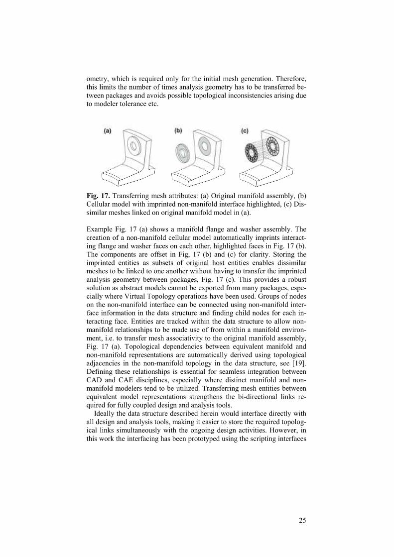
Fig. 17. Transferring mesh attributes: (a) Original manifold assembly, (b)
Cellular model with imprinted non-manifold interface highlighted, (c) Dis-
similar meshes linked on original manifold model in (a).
Example Fig. 17 (a) shows a manifold flange and washer assembly. The
creation of a non-manifold cellular model automatically imprints interact-
ing flange and washer faces on each other, highlighted faces in Fig. 17 (b).
The components are offset in Fig, 17 (b) and (c) for clarity. Storing the
imprinted entities as subsets of original host entities enables dissimilar
meshes to be linked to one another without having to transfer the imprinted
analysis geometry between packages, Fig. 17 (c). This provides a robust
solution as abstract models cannot be exported from many packages, espe-
cially where Virtual Topology operations have been used. Groups of nodes
on the non-manifold interface can be connected using non-manifold inter-
face information in the data structure and finding child nodes for each in-
teracting face. Entities are tracked within the data structure to allow non-
manifold relationships to be made use of from within a manifold environ-
ment, i.e. to transfer mesh associativity to the original manifold assembly,
Fig. 17 (a). Topological dependencies between equivalent manifold and
non-manifold representations are automatically derived using topological
adjacencies in the non-manifold topology in the data structure, see [19].
Defining these relationships is essential for seamless integration between
CAD and CAE disciplines, especially where distinct manifold and non-
manifold modelers tend to be utilized. Transferring mesh entities between
equivalent model representations strengthens the bi-directional links re-
quired for fully coupled design and analysis tools.
Ideally the data structure described herein would interface directly with
all design and analysis tools, making it easier to store the required topolog-
ical links simultaneously with the ongoing design activities. However, in
this work the interfacing has been prototyped using the scripting interfaces
26
to certain packages. It has been shown that the links between different de-
sign and analysis geometries can be identified without having to interact
with all packages in the design process. For example, it is possible to iden-
tify the links between the design and analysis geometry without having to
interact with the simplification tools used to create the analysis geometry.
This highlights the robustness of this approach, enabling the desired tools
to be used for certain applications without having to consider the down-
stream effect. The memory overhead for the database is insignificant for
the small models presented here. For industrial design applications the da-
tabase memory overhead will depend on component complexity, the num-
ber of equivalent representations and the meshing attributes used. It is an-
ticipated this overhead will be small relative to the corresponding CAD
and CAE data files and structures.
Another method to find the Virtual Topology relationships described in
Section 4 is to use the Identifier of a topological entity. If a package con-
tains geometric searching functionality the Identifier information in the da-
tabase can be used to identify entities that have been merged together. The
Identifier contains the coordinates of a position within the boundary of an
entity and can be used to find the closest entity located at those coordi-
nates. A simple query on the database returns the Identifier of all edges
and faces in the host model. The virtual model is interrogated to find the
closest edges and faces for each Identifier. Entities in the virtual model
containing multiple host Identifiers are superset entities.
In order to demonstrate the effectiveness of the proposed approach Sec-
tion 6 describes how analysis geometry can be automatically linked to its
equivalent original representation, allowing for robust transfer of the mesh.
Once appropriate models have been created the approach is fully automat-
ed and can be used to establish the equivalence between any number of
CAD or analysis models from a variety of sources. Analysis attributes
have been transferred between models at various levels of fidelity within
Siemens NX, Abaqus, CADFix and Parasolid. Since Parasolid is the un-
derling modelling kernel of other CAD and CAE packages (SolidWorks,
Ansys and MSC Patran), extending the current toolset to include these
packages requires only implementation since the Parasolid data structure is
utilized. While the analysis geometry used for the example in Figs. 14 and
15 is the output from a decomposition tool, other simplified models can al-
so be integrated using the proposed approach. In terms of linking dimen-
sionally reduced entities more details are provided in [9] and [19]. Once
relationships have been established between dimensionally reduced cells
and their equivalent original representation, mesh parentage relationships
can be transferred between the models as described throughout this paper.
An application to models of industrial complexity is described in [8] and
[19] for equivalent decomposed and dimensionally reduced model repre-
sentations.

27
Robust transfer of meshes between different models and packages ena-
bles boundary conditions and other analysis attributes applied to the origi-
nal model to be automatically transferred to a mesh generated on abstract
analysis geometry. During automatic Virtual Topology operations there is
the possibility that topological entities with boundary conditions applied
may be merged with adjacent entities. It has been assumed in this work
that entities with boundary conditions applied will not be involved in
downstream clean-up operations. In practice it may be necessary to store
the original topology in the database along with pointers to entities with
boundary conditions applied to ensure these entities would be preserved.
Additionally, boundary conditions can be attached to virtual entities, where
for example virtual subsets may be created to apply contact between faces.
One current limitation is for mixed solid meshing and the treatment of
non-conforming interface regions, i.e. hex and tet meshes meeting at a
common face results in a non-conforming mesh at the interface. The dis-
tinct meshes can be coupled using multi-point constraint equations or by
inserting transition elements, such as pyramids. For example, the node in-
sertion method [12] can be used to partition hex elements at a non-
conforming interface by inserting a node at the centroids of the hexes, gen-
erating two tet elements and five pyramid elements and creating conformi-
ty at the interface. The non-manifold model utilized in this work enables
interface elements to be easily identified so that they can be partitioned.
Once partitioned, the resulting tet and pyramid elements are considered as
subsets of the original hex element. In cases where it is desirable to pre-
serve the hex elements at the interface, conformity may be achieved by
merging adjacent tet elements together. The new pyramid elements are
considered virtual supersets of the original tet elements. In this manner
Virtual Topology is extended to manage different decompositions of
equivalent meshes, allowing multiple mesh representations to be linked to
the same base geometry.
8 Conclusions
Novel techniques have been presented in this paper to facilitate the transfer
of finite element meshes between equivalent analysis geometries residing
in different CAE packages, without any loss of integrity. This is achieved
by tracking the equivalences between all cells in the equivalent design and
analysis models. Virtual Topology merging and partitioning are used to
create a cellular decomposition of the design space, which provides a
framework upon which to specify all the necessary analysis attributes.
In order to transfer the mesh between packages, the simplified analysis
model is linked to its equivalent design model. Equivalent relationships are
stored in a robust manner so they can be reused downstream in different

28
packages, enabling mesh-geometry ownership to be transferred between
the models at different levels of abstraction and fidelity. Therefore, bound-
ary conditions applied to an original model can be automatically trans-
ferred to the finite element mesh generated on abstract analysis geometry.
This enables toolsets of choice to be selected by an analyst without having
to manually link models, resulting in an integrated analysis process. This
integration allows analysis model pre-processing tasks (geometry clean-up
and decomposition) and analysis setup (loading and boundary conditions)
to be carried out concurrently.
References
1. Arabashi, S.D., Barton, C. and Shaw, N.K., “Steps towards cad-fea integra-
tion,” Engineering with Computers, vol. 9, no. 1, pp. 17-26, 1993.
2. Beall, M.W. and Shephard, M.S., “Accessing CAD geometry for mesh
generation,” in 12th International Meshing Roundtable, Santa Fe, 2003.
3. Cavalcanti, P.R., Carvalho, P.C. and Martha, L.F., “Non-manifold modeling:
An approach based on spatial subdivision,” Computer-Aided Design, vol. 29,
no. 3, pp. 209-220, 1997.
4. Donaghy, R.,McCune, W., Bridgett, S., Armstrong, C. G.Robinson, D.J. and
McKeag, R. M., “Dimensional reduction of analysis models,” in Proceedings
of the 5th International Meshing Roundtable, 1996.
5. Harlin, G., “Engineering value of simulation process and data-management
applied to aero engine design,” in Nafems World Congress, Salzburg, 2013.
6. Lee, J.Y., Lee, J.H., Kim, H., Kim, H.S., “A Cellular topology-based approach
to generating progressive solid models from feature-centric models”, Comput-
er-Aided Design, vol. 36, no. 3, pp. 217–229, 2004.
7. Lee, S.H., “A CAD-CAE integration approach using feature based multi-
resolution and multi-abstraction modeling techniques,” Computer-Aided De-
sign, pp. 941-955, 2005.
8. Makem, J.E., Armstrong, C.G. and Robinson, T.T., “Automatic decomposi-
tion and efficient semi-structured meshing of complex solids,” Engineering
with Computers, pp. DOI: 10.1007/s00366-012-0302-x, 2012.
9. Nolan, D.C., Tierney, C.M., Armstrong,C.G., Robinson,T.T. and Makem,J.E.,
“Automatic dimensional reduction and meshing of stiffened thin-wall struc-
tures,” Engineering with Computers, DOI: 10.1007/s00366-013-0317-2013.
10. Nolan, D.C., Tierney, C.M., Armstrong,C.G., Robinson,T.T, “Automating
analysis modelling though the use of Simulation Intent,” 2013. Paper present-
ed at NAFEM World Congress, Salzburg, Austria.
11. Owen, S.J. and Shepherd, J.F., “Embedding features in a Cartesian grid,” in
18th International Roundtable, Salt Lake City, 2009.
12. Owen, S.J., Cannan, S.A. and Saigal, S., “Pyramid elements for maintaining
tetrahedra to hexahedra conformity,” ASME, pp. 123-129, 1997.
13. Robinson, T.T., Armstrong, C.G. and Fairey, R., “Automated mixed dimen-
sional modeling from 2d and 3d cad models,” Finite Elements in Analysis and
Design, vol. 47, no. 2, pp. 151-165, 2011.

29
14. Sheffer, A., Blacker, T., Bercovier, M., “Virtual Topology Operators for
Meshing”, International Journal of Computational Geometry and Applica-
tions, 10(3), 309-331, 2000.
15. Shephard, M. S., Beall, M.W., O'Bara, R.M. and Webster, B.E., “Toward
simulation-based design,” Finite Elements in Analysis and Design, pp. 1575-
1598, 2004.
16. Sypkens Smit, M and Bronsvoort, W.F., “Integration of Design and Analysis
Models,” Computer-Aided Design and Applications, pp. 795-808, 2009.
17. Sypkens Smit, M and Bronsvoort, W.F., “Efficient tetrahedral remeshing of
feature models for finite element analysis,” Engineering with Computers, vol.
25, pp. 327-344, 2009.
18. Thakur, A., Banerjee, A.G. and Gupta, S.K., “A survey of CAD model simpli-
fication techniques for physics-based simulation applications,” Computer-
Aided Design, vol. 41, pp. 65-80, 2009.
19. Tierney, C.M., Nolan, D.C., Robinson, T.T. and Armstrong, C.G., “Managing
equivalent representations of design and analysis models,” Computer-Aided
Design and Applications, 11:2, 193-205, DOI:
10.1080/16864360.2014.846091, 2014.
20. Weiler, K., “The Radial Edge Structure,” in Geometric Modeling for CAD
applications, North-Holland, 1988, pp. 3-36.
21. White, D. and Saigal, S., “Improved imprint and merge for conformal mesh-
ing,” in 11th International Meshing Roundtable, New York, 2002.