Embed Size (px)
Citation preview

w w w. z e e v e e . c o m
Using Maestro
Connecting to Maestro
To use Maestro, you first need to connect to it through the computer.
1. Connect your computer directly to the ZeeVee modulator using a standard Ethernet cable (not a cross-over cable) or connect the unit and your computer to any LAN that has a DHCP server.
2. An IP address appears at the top of the front panel display.
3. Using any web browser (Chrome or Firefox preferred), enter the IP address to launch Maestro.
4. You will be directed to a login page. Your user name is always “admin.” The default password is “admin” but you can change the password. Login is case-sensitive.
5. After you log in, the Maestro Status tab appears. Here you can see the general information about the unit.
A P P L I C A T I O N N O T E
The Maestro tool contains the following tabs, each with its own ways of customizing your system:
•Statustab•ChannelPlantab•RFtab•Devicetab•Networktab•STBtab•Supporttab•Abouttab
IP address
What is Maestro?
Maestro is a configuration tool that you use optionally to customize your ZeeVee system beyond what is allowed in the front panel. For example, using Maestro you can assign a channel number (virtual channel) independent of the RF number, label the channels and manage all ZeeVee units on your network.
You can use Maestro with ZvPro and HDbridge 2000 series units, though the offerings and functionality may change depending on the model.
NA

N A | 2w w w. z e e v e e . c o m
U S I N G M A E S T R O
Selected Box – Tells you how many units selectedforconfigurationforusewiththe Set All function. Selected units are indicatedwithacheckedbox.
Manage All –Clickthis button to view and configureallunitsonyournetwork.Thisfunctionpulls in only systems with matching passwords and similarfirmware.
Refresh All –Clickthisbutton to refresh system data.
Managing Units on the Network
Maestro gives the option of viewing and managing one, many, or all units on the network.
Connected and Not Connected Status – Shows the total number of units discoveredonthenetworkandthenumberconnectedformanagementinMaestro.
The “connected” units are available for management in the current Maestro session (unitsnotconnectedmaycontaindifferentpasswordsorrunout-of-datefirmware).Only connected units are pulled into Maestro for management.
If you are managing just a single unit, the display will show, for example, “1 connected, 9 not connected,” which means there are a total of 10 units on the network. Hit Manage All which connects to multiple units, and it may show “9 connected, 1 not connected.” That one unit not connected has either a password and/or firmware that is different from the others and until changed, cannot be managed in the Manage All set up.

N A | 3w w w. z e e v e e . c o m
U S I N G M A E S T R O
Naming the Units (Auto-Name)
Auto-Name –EnterastartingunitnamehereandMaestroautomaticallyincrementsdownandnamesthefullrackof units (for example, mod_1 then second in line, mod_2, third is mod_3).
Entering a starting name prompts the user to hit buttons on the ZeeVee unit. Maestro then names each unit in order of the buttons pressed.
N A | 4w w w. z e e v e e . c o m
U S I N G M A E S T R O
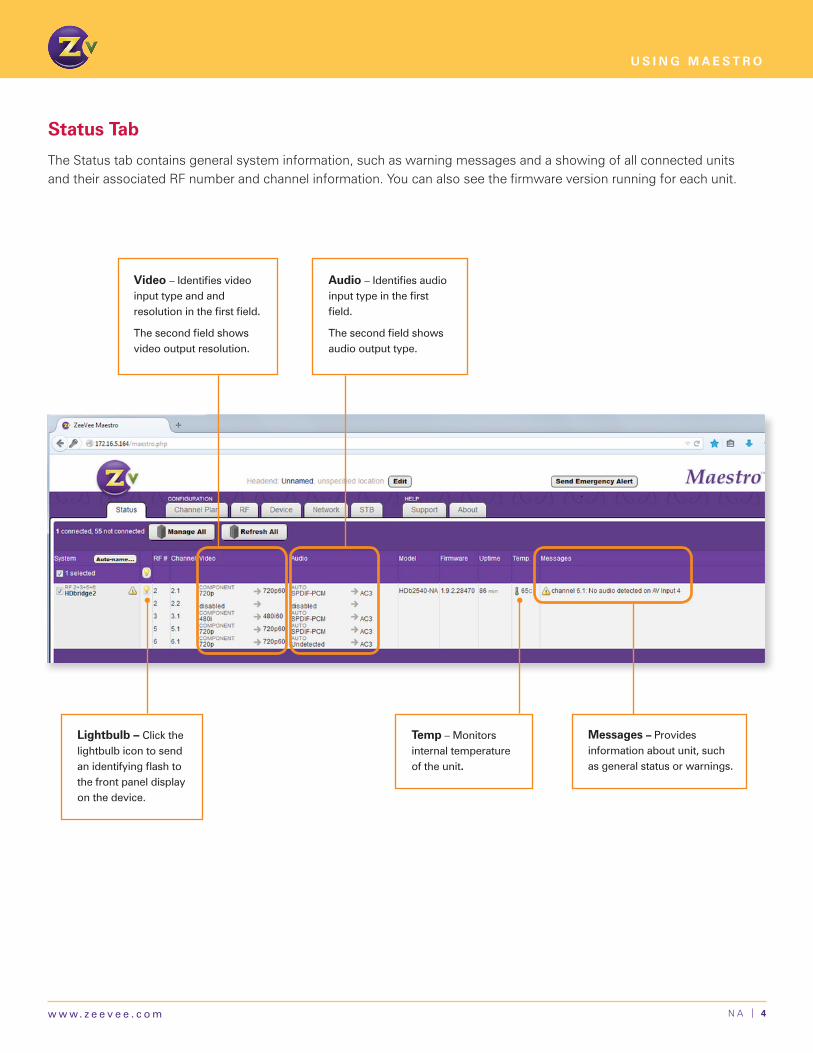
Messages – Provides information about unit, such as general status or warnings.
Video –Identifiesvideoinput type and and resolutioninthefirstfield.
Thesecondfieldshowsvideo output resolution.
Audio –Identifiesaudioinputtypeinthefirstfield.
Thesecondfieldshowsaudio output type.
Lightbulb – Clickthelightbulb icon to send anidentifyingflashtothe front panel display on the device.
Temp – Monitors internal temperature of the unit.
Status Tab
The Status tab contains general system information, such as warning messages and a showing of all connected units and their associated RF number and channel information. You can also see the firmware version running for each unit.

N A | 5w w w. z e e v e e . c o m
U S I N G M A E S T R O
1. ClickSetAllandselectAuto-increment.
2. Enterthefirstnumber(RF#,Channel#,Prog#orIPaddress)youwishtouse.Maestrothenautomaticallyincrements down and assigns all subsequent numbers or addresses.
ForChannel#,enterthestartingchannelorselectoptiontomatchthechanneltotheRFchannel.
When Increment major numbers only ischecked,onlythenumberbeforethe“.”willincrement(themajornumber, the number after “.” is the minor number). For example, enter 50.1, and the channels will increment 51.1, 52.1, and so on.
FormoreinformationonRF#/Channel#andProg#seepages6and8.FordetailsonIPAddress,seepage15.
3.ClickSetandchannelsorIPaddressesupdateforyourreview.TheyarenotsaveduntilyouclickApplyontheChannelPlanorNetworkpage.
Using Set All and the Auto-Increment Function
The Set All feature allows you to apply settings to all managed units. Most configuration options offer the Set All feature so that you can change settings across multiple units.
When you choose Set All for RF#, Channel#, Prog# (Channel Plan tab) and IP address (Network tab), the Auto-Increment function allows you to set information in a few easy steps.
Apply –Clicktosavechanges.
Reset – Clicktoclearany changes that have not been saved.

N A | 6w w w. z e e v e e . c o m
U S I N G M A E S T R O
RF # –AllowsyoutoentertheRFfrequencyforbroadcast.RF#sarepairedtogetherbyfrequency.WhenyouupdatethefirstRFnumber,thesecondupdatesautomatically.RefertotheRFFrequencyMapandImportantNoteson page 21 for details.
Channel # – Allows you to enter a channel number (virtual channel). The channel number is what the TV displays andcanbeindependentoftheRF#.Youcanconfigureachannelnumbertwoways:
1. As a dotted number — Enter the number with a “.” following it, for example, “5.1”. This is the default display.
2. Asadotlessnumber—Enterthenumberwitha“#”precedingit,forexample,“#5”.NotethatyoucanchooseachannelnumberthatisdifferentfromtheRF#.Forinstance,ifyourRF#is3,youcanchooseachannelnumberof10.1or#10.
Choosing Set All for RF number and Channel Number requires you to set up Auto-Increment. See page 5.
Help – Clicktodisplaytab-specifichelptext.
Channel Plan Tab — Setting Basic Channel Information
The Channel Plan tab allows you to configure RF numbers and virtual channels.
Apply –Clicktosavechanges.
Reset – Clicktoclearany changes that have not been saved.
Updated versions of firmwareofferthisZvShow “extra” channel. For more information, see page 12.

N A | 7w w w. z e e v e e . c o m
U S I N G M A E S T R O
Video Source – Allows you to select the video input that is encoded and broadcast.
Audio Source – Allows you to select the audio input that is encoded and broadcast. You can also set this to “None” so that Maestro is not constantly searching for audio.
Auto is the default for most units. The Auto setting automatically detects the type of audio and video.
Enabled – Lets you choose to “enable” or “disable” the particular channel. If one of the inputs is not being used, disable the channel so thattheTVwon’tdisplayit.RFisstilloccupied with a disabled channel.
Name – Allows you to enter the channel short name (up to 7 characters).
Long Name – Allows you to add a longer or more descriptivenametothechannel(upto63characters).
The TV displays the Name and Long Name when the channel is changed or if the info guide information is requested.
Each TV handles the name display differently.
Rating – Allows you to assign an audience rating for all entries in the program guide. Choose from the TV parental guidelines provided in the drop down list. The values sent followMPEG2andCEA-766specification,region1(USA),dimension0(TV-Rating).NotethatTV-MA-LSVisthemostextreme content, with LSV short for “Language, Sex, Violence.
Theratingdefinedhereappliestoallcontentonthechannel.
YoucanusetheRatingsettingwithprogramssuchasVChip.
Channel Plan Tab — Setting More Channel Information
The Channel Plan tab allows you to label channels and their content.
N A | 8w w w. z e e v e e . c o m
U S I N G M A E S T R O
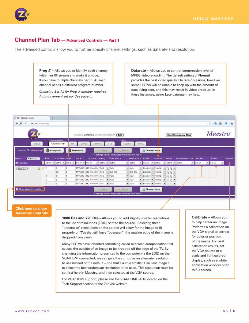
Channel Plan Tab — Advanced Controls — Part 1
The advanced controls allow you to further specify channel settings, such as datarate and resolution.
1080 Res and 720 Res – Allows you to add slightly smaller resolutions to the list of resolutions (EDID) sent to the source. Selecting these “underscan”resolutionsonthesourcewillallowfortheimagetofitproperly on TVs that still have “overscan” (the outside edge of the image is dropped from view).
Many HDTVs have inherited something called overscan compensation that causestheoutsideofanimagetobedroppedofftheedgeoftheTV.Bychanging the information presented to the computer via the EDID on the VGA/HDMIconnected,wecangivethecomputeranalternateresolutionto use instead of the default – one that’s a little smaller. Use Test Image 1 to select the best underscan resolution to be used. This resolution must be setfirsthereinMaestro,andthenselectedattheVGAsource.
ForVGA/HDMIsupport,pleaseseetheVGA/HDMIFAQslocatedontheTech Support section of the ZeeVee website.
Calibrate – Allows you to help center an image. Performs a calibration on the VGA signal to correct for color or position of the image. For best calibration results, set the VGA source to a static and light colored display, such as a white application window open to full screen.
Datarate – Allows you to control compression level of MPEG video encoding. The default setting of Normal provides the best video quality. On rare occasions, however, someHDTVswillbeunabletokeepupwiththeamountofdatabeingsent,andthismayresultinvideobreakup.Inthese instances, using Low datarate may help.
Prog # – Allows you to identify each channel withinanRFstreamandmakeitunique. IfyouhavemultiplechannelsperRF#,eachchannel needs a different program number.
Choosing Set All for Prog # number requires Auto-increment set up. See page 5.
Click here to show Advanced Controls

N A | 9w w w. z e e v e e . c o m
U S I N G M A E S T R O
Channel Plan Tab — Advanced Controls — Part 2
The following advanced controls allow you to make small adjustments to audio/video latency for lip sync purposes, to match audio to external audio system, and to adjust color for the best video quality.
Delayed Audio Out – Allows you to match audio to externalaudiosystem(firstportonly).Whenusingadistributed or whole-house audio system you can use thisfunctiontosendaudiofromthefirstinput(requiresanalog audio input) to your distributed audio system. Bydefaultthisportwillhavea400msdelay,butcanbeadjustedbetween0and2000mstomatchthespecificlatency of your modulated channel.
Delayed Audio Out is available only on HDbridge 2312, 2840,2920andZvPromodels.
Color (HDb2312 only) – The default values are set for the best brightness, contrast, saturation, and hue for most sources. In rare occasions composite sources sources may need adjustmentforthebestvideoquality.
Brightnesscontrolrangesfromdarkblackleveltoverybrightblacklevel(defaultsettingis112).Contrastcontrolrangesfromminimum white level to maximum white level (default setting is 128).Saturationcontrolrangesfromnocolortomaximumcolor(defaultsettingis128).Huecontrolrangesfrom0to255thatindicate-180to+180degreeofcolorphase(defaultsettingis128).
(Field Not Pictured Below)
Delays – Allowsyoutomakesmalladjustmentstoaudio/videolatencyforlipsyncpurposes.
In rare deployments, audio may not arrive to the ZeeVee device perfectly synchronized with the video. When this happens, the picture on the HDTV has a “lip sync” issue.
Additionally, the overall amount of latency in the video and audio stream can affect the picture quality. A higher latency can increase the picture quality and ensures compatibility with some older HDTVs, while a lower latency results in a faster response.
Youcanmodifybothaudioandvideodelaytoadjustlipsyncandlatency.Dragthecenteradjustmentbartoadjustoveralllatencywhilekeepinglipsyncthesame,andadjustthetopandbottomarrowstoadjustlipsync.Thesettingof6isapproximately220msoflatency.Eachunit(6-12forvideoand6-16foraudio)equalsapproximately32ms.
Click here to show Advanced Controls

N A | 1 0w w w. z e e v e e . c o m
U S I N G M A E S T R O
RF Tab
In the RF tab, you can configure RF information for individual units, such as changing the RF power output, stopping broadcast, and defining a cable plan.
Cable Plan – AllowsyoutodefineacableplanotherthanthedefaultQAMStandard.Ifcombiningwithanexistingcable service, the cable plan must match the cable service.
RF Power – AllowsyoutochangetheoutputRFpowerofthedevice.WhenusingZeeVeehardwaretoaddachanneltoanexistinglineup,youneedtomatchthepowerofexistingchannels(otherwiseadjacentlower-poweredchannelscanbedifficulttotunewithsometelevisions).RFPowercanbesettodifferentlevelsbetweenpairsofRFs,buttheymustbewithin12dbmvofeachother.Unitscanbesetbetween+25dBmVand+45dBmVin1dbincrements.
HDbridge models have a default option of +45dBmV. ZvPro models have a default option of +25dBmV.
RF On/Off – AllowsyoutodisabletheRFoutput(allbroadcast).Settingthisfieldto“Off”willmakeanyassociatedchannelsdisappearfromyourcablenetwork.

N A | 1 1w w w. z e e v e e . c o m
U S I N G M A E S T R O
RF Tab — Advanced Controls
Click here to show Advanced Controls
PID – AllowsyoutodefinetheprogramIDforeachMPEG2packet.Eachpackethasauniqueidentifierintheheaderthatassociateseachpacketwiththeproperprogram.Thiscommandsetsthe starting PID number that will be used for all transmissions. It is called the starting number becausefourPIDsareallocated.ThefirstisforVideopackets,thesecondisforAudio,thethirdisfor the Program information and the fourth is for control information. Used rarely and only if you have a custom set top box to tune in our signal.
Any time the PID is changed, the unit must be restarted for the new value to take effect.
QAMs –Allowsyoutochoosebetweendouble(default)andsingle.SingleQAMmodeallowsformultipleprogramsperRF.Forexample,RF2withprograms2.1and2.2;whiledoublemodesendsasingleprogram(video/audiosource)perRF.
Doublemodeallowsforgreatervideoqualityespeciallywithhigherresolutionslike1080.Whenindoublemode,theRFfrequencieswillbepairedsoonlythefirstRFinthepairisconfigurable.ThesecondRFwillbeassignedautomaticallybasedonthe6MHzfrequencybandthatisadjacenttothefirstRFassigned.RF channels do not always go in numerical order with the frequencies. See the chart on page 21 more information on RF channels and frequency.
Changing between single and double mode will cause the unit to reset to factory defaults (IPaddressandpasswordaswellasallchannelconfiguration)insomefirmwareversions.
RF Modulation – Allows you definemodulationschemesfordigitalcable(defaultQAM-256).QAM-256allowsforahigherbitratethanQAM-64,butsomeinstallationsmaypreferQAM-64tofitintotheirnetworkbetter.QAM-64isonlyavailablewhentheunitisin“DoubleQAM”mode. Video quality may be degradedwhenrunningQAM-64.
N A | 1 2w w w. z e e v e e . c o m
U S I N G M A E S T R O
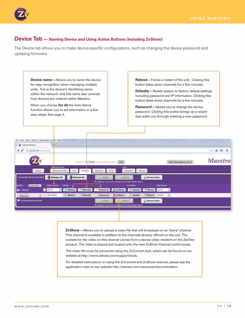
Device Tab — Naming Device and Using Action Buttons (Including ZvShow)
The Device tab allows you to make device-specific configurations, such as changing the device password and updating firmware.
Reboot –Forcesarestartoftheunit.Clickingthisbuttontakesdownchannelsforafewminutes.
Defaults – Resetssystemtofactorydefaultsettings,includingpasswordandIPinformation.Clickingthisbuttontakesdownchannelsforafewminutes.
Password – Allows you to change the device password.Clickingthisbuttonbringsupawizardthatwalksyouthroughenteringanewpassword.
ZvShow –Allowsyoutouploadavideofilethatwillbroadcastonan“extra”channel.This channel is available in addition to the channels already offered on the unit. The content for the video on this channel comes from a stored video resident on the ZeeVee product. The video is played and looped onto the new ZvShow Channel continuously.
ThevideofilemustbeconvertedusingtheZvConverttool,whichcanbefoundonourwebsiteathttp://www.zeevee.com/support/tools.
For detailed instructions on using the ZvConvert and ZvShow channel, please see the applicationnoteonourwebsitehttp://zeevee.com/resources/documentation.
Device name – Allows you to name the device for easy recognition when managing multiple units. This is the device’s identifying name withinthenetwork,andthisnamealsocontrolshow devices are ordered within Maestro.
When you choose Set All the Auto-Name function allows you to set information in a few easy steps. See page 3.

N A | 1 3w w w. z e e v e e . c o m
U S I N G M A E S T R O
Device Tab — Choosing Firmware and Idle Screen
Idle Screen – Allows you to upload a custom image that displays when no video is detected in the video port. Otherwise,thedefaultimageofaZeeVeelogowilldisplayagainstablackbackground.
HD products such as the ZvPro line and HDbridge 2500/2600, 2840 and 2920 models require the image to have a resolution of 1280x720 or smaller. If the image is 1264x704 or smaller the image will move around the screen, otherwise it will remain static and be centered.
The HDbridge 2380 and 2312 require an image size of 720x480 or smaller. If the image is 704x464 or smaller the image will move around the screen, otherwise it will remain static in the center of the screen.
File formats accepted for all models are gif, jpg, jpeg, png and bmp. The image is not scaled.
Update – Allowsyoutobrowsethesavedfirmwarefile.
Find and then download the most updated firmware in the Firmware section of the Support section on our website.
Revert – Allowsyoutorevertbacktothepreviouslyinstalledversionoffirmware.Usethisfunctionifarecentfirmwareupdatehasmadeachangethatisnotcompatiblewith your current set up or if you have issues with a firmwareupdate.
Both firmware update and firmware revert will automatically reboot the unit.
N A | 1 4w w w. z e e v e e . c o m
U S I N G M A E S T R O
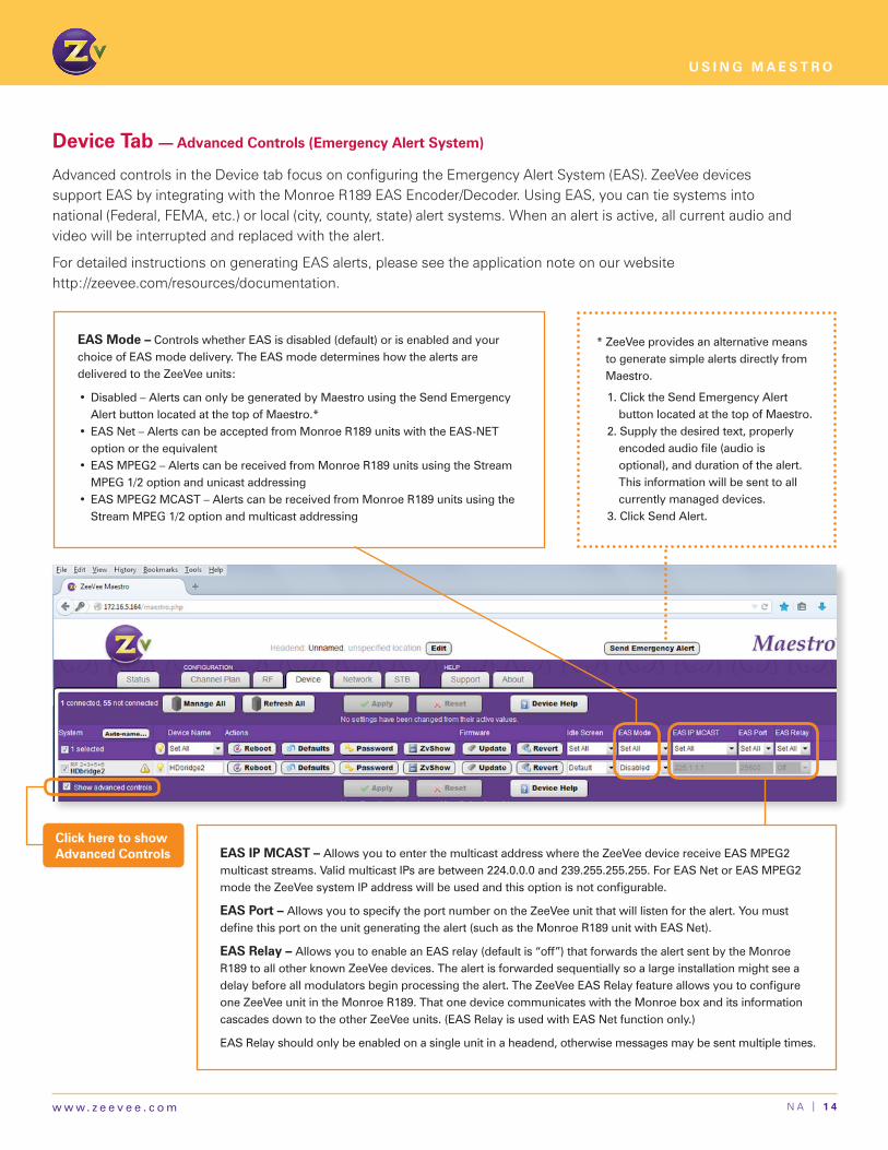
Device Tab — Advanced Controls (Emergency Alert System)
Advanced controls in the Device tab focus on configuring the Emergency Alert System (EAS). ZeeVee devices support EAS by integrating with the Monroe R189 EAS Encoder/Decoder. Using EAS, you can tie systems into national (Federal, FEMA, etc.) or local (city, county, state) alert systems. When an alert is active, all current audio and video will be interrupted and replaced with the alert.
For detailed instructions on generating EAS alerts, please see the application note on our website http://zeevee.com/resources/documentation.
EAS IP MCAST – Allows you to enter the multicast address where the ZeeVee device receive EAS MPEG2 multicaststreams.ValidmulticastIPsarebetween224.0.0.0and239.255.255.255.ForEASNetorEASMPEG2modetheZeeVeesystemIPaddresswillbeusedandthisoptionisnotconfigurable.
EAS Port – Allows you to specify the port number on the ZeeVee unit that will listen for the alert. You must definethisportontheunitgeneratingthealert(suchastheMonroeR189unitwithEASNet).
EAS Relay – Allows you to enable an EAS relay (default is “off”) that forwards the alert sent by the Monroe R189toallotherknownZeeVeedevices.Thealertisforwardedsequentiallysoalargeinstallationmightseeadelaybeforeallmodulatorsbeginprocessingthealert.TheZeeVeeEASRelayfeatureallowsyoutoconfigureoneZeeVeeunitintheMonroeR189.ThatonedevicecommunicateswiththeMonroeboxanditsinformationcascadesdowntotheotherZeeVeeunits.(EASRelayisusedwithEASNetfunctiononly.)
EASRelayshouldonlybeenabledonasingleunitinaheadend,otherwisemessagesmaybesentmultipletimes.
Click here to show Advanced Controls
EAS Mode – Controls whether EAS is disabled (default) or is enabled and your choice of EAS mode delivery. The EAS mode determines how the alerts are delivered to the ZeeVee units:
•Disabled–AlertscanonlybegeneratedbyMaestrousingtheSendEmergencyAlert button located at the top of Maestro.*
•EASNet–AlertscanbeacceptedfromMonroeR189unitswiththeEAS-NEToption or the equivalent
•EASMPEG2–AlertscanbereceivedfromMonroeR189unitsusingtheStreamMPEG1/2optionandunicastaddressing
•EASMPEG2MCAST–AlertscanbereceivedfromMonroeR189unitsusingtheStreamMPEG1/2optionandmulticastaddressing
ZeeVee provides an alternative means to generate simple alerts directly from Maestro.
1.ClicktheSendEmergencyAlertbutton located at the top of Maestro.
2. Supply the desired text, properly encodedaudiofile(audioisoptional), and duration of the alert. This information will be sent to all currently managed devices.
3.ClickSendAlert.
*

N A | 1 5w w w. z e e v e e . c o m
U S I N G M A E S T R O
Network Tab — Assigning IP Type and Address
IP Type – DefinestheIPaddressthedeviceuses,eitherusesaDHCP(default)togetadynamicIPaddress or a static IP address. After saving changed IP type, the system requires a reboot to initiate the new IP address.
IP Address — DisplaysandallowsyoutoconfigurethecurrentIPaddressoftheunit.IfyouchooseSet All here, Maestro uses its auto-increment function to assign subsequent addresses (see page 5).
Mask and Def Gateway – Enterthesubnetmaskyouwanttouse.TheMaskfieldisrequired.
WhenusingastaticIPaddress,youmustconfiguretheIPAddress,Mask,andDefaultGatewaymanually. When using DHCP, these settings are assigned dynamically.

N A | 1 6w w w. z e e v e e . c o m
U S I N G M A E S T R O
Network Tab — Advanced Controls
Click here to show Advanced Controls
DNS 1, DNS 2 – (Optional setting) Used only when assigning static IP address.
NTP 1, NTP2 – NetworkTimeProtocol(NTP)is an optional setting used to assign time on the networkorunit.Thissettingisrequiredwhenusingthe Emergency Alert System (EAS) and can bet set whether IP address is static or DHCP.
Mac Address – This address is for information only and cannot be edited.

N A | 1 7w w w. z e e v e e . c o m
U S I N G M A E S T R O
STB Tab (Controlling Set Top Boxes)
The STB tab enables ZvSTB control functionality, which allows for simple control of H25 DirecTV receivers (also called set top box) through Maestro.
To use ZvSTB Control, first you configure the set top box and then you configure Maestro to manage the box.
For detailed instructions on using ZvSTB, please see the application note on our website http://zeevee.com/resources/documentation.
CONFIGURING STB DEVICE FIELDS
IP address – Enter the IP address of the given set top box. To view and manage individual set top box units, you need to enter the proper IP addressforthegivenboxinitsassociatedinputfield.IfanIPaddressisnotpresentintheSTBIPAddressfieldforagiveninput,theZeeVeeunitdoes not enable remote management operations.
Receiver ID and Access card ID# – ID information from the receiver.
The Call Sign Name, Program Name, Receiver ID, and Access Card values are all updated and displayed at regular intervals. These are informational and helpful to determine which STB is connected.

N A | 1 8w w w. z e e v e e . c o m
U S I N G M A E S T R O
STB POWER
Config – Allows you to power individual unit “on” or “off.”
Actual – Shows whether individual unit is powered on or off.
Force – Allow you to enable (or disable), the associated set top box to “force” the setting you specify. With Force enabled, Maestro will query the box automatically and periodically and set the command toyourconfiguration.Forexample,if the set top box is turned off, yet it’sconfiguredinMaestroas“on,”an enabled Force sends a command to set the power on to match the Maestro setting.
STB Tab — Setting Power, Channel Number, and Channel Names
Theentireblockofsettopboxunitsunder management can be controlled simultaneouslybyclickingSetAlloption at the top of the column.
STB CHANNEL NUMBER
Config – Allows you to enter the desiredchannelnumberfortheSTB.
Actual – Indicates the current channelsettotheSTBforthespecifiedinputport(ontheZeeVeeunit).
Force – Allow you to enable (or disable), the associated set top box to “force” the setting you specify. With Force enabled, Maestro periodicallyqueriestheSTBandwill automatically change the configurationsettingstothosesetintheSTBtab.Forexample,if“242”appearsintheActualfield,yetit’sconfiguredinMaestroas“142,”anenabled Force sends a command to setthechannelto142tomatchtheMaestro setting.
STB CHANNEL NAMES
Call Sign – Displays channel call sign – for example, “CNN.”
Program Name – Displays channel name associated with call sign – for example, “CNN newsroom.”
Link – Allows you to enable or disable the ZeeVee channel so that you can edit the Call Sign and ProgramNamefields.Youcannoteditthesefieldswhenthisoptionisenabled.

N A | 1 9w w w. z e e v e e . c o m
U S I N G M A E S T R O
Support Tab
The Support tab provides general information on the units and helps you troubleshoot issues.
Send Troubleshooting Report – Gathers all relevant log and configurationinformationandgenerates a report to help troubleshoot issues. If the unit is connected to the internet, Maestro sends report directly to a ZeeVee Support server. Otherwise,itwillprovidealinkwhereyou can download the report and email it to ZeeVee.
Clickintheboxtogenerateafullreport (this will temporarily disable video input to the TVs while it is generating.)

N A | 2 0w w w. z e e v e e . c o m
U S I N G M A E S T R O
Naming Units in a Headend
You can assign a name to all units in a headend by clicking on the Edit button of Maestro. If you are managing multiple head ends in different locations, you can name them as a whole for easier management.
Edit Headend – Headend information allows you to assign a name (as well as notesabouttheheadend),whichmakesmanagingmultipleheadendsacrossmultiple locations easier. This naming function is especially helpful for identifying units that you manage remotely.

N A | 2 1w w w. z e e v e e . c o m
U S I N G M A E S T R O
Map for Configuring RF Numbers and Virtual Channels
The Cable TV Channels vs RF Frequency (MHz) Map shows how the RF channels are paired and matched with RF frequency. You will need to refer to this map when configuring RF numbers and virtual channels.
Cable TV Channels vs RF Frequency (MHz) Map
RF Ch. Band (MHz) RF Ch. Band (MHz) RF Ch. Band (MHz) RF Ch. Band (MHz) RF Ch. Band (MHz)
2 54-60 27 240-246 57 420-426 87 600-606 122 780-786
3 60-66 28 246-252 58 426-432 88 606-612 123 786-792
4 66-72 29 252-258 59 432-438 89 612-618 124 792-798
5 76-82 30 258-264 60 438-444 90 618-624 125 798-804
6 82-88 31 264-270 61 444-450 91 624-630 126 804-810
95 90-96 32 270-276 62 450-456 92 630-636 127 810-816
96 96-102 33 276-282 63 456-462 93 636-642 128 816-822
97 102-108 34 282-288 64 462-468 94 642-648 129 822-828
98 108-114 35 288-294 65 468-474 100 648-654 130 828-834
99 114-120 36 294-300 66 474-480 101 654-660 131 834-840
14 120-126 37 300-306 67 480-486 102 660-666 132 840-846
15 126-132 38 306-312 68 486-492 103 666-672 133 846-852
16 132-138 39 312-318 69 492-498 104 672-678 134 852-858
17 138-144 40 318-324 70 498-504 105 678-684 135 858-864
18 144-150 41 324-330 71 504-510 106 684-690
HRC Frequencies =
Standard Frequencies
minus 1.25 MHz
Except for:
Channel 5, Video = 78.0 MHz
Channel 6, Video = 84.0 MHz
IRC Frequencies =
Same as Standard Frequencies
Except for:
Channel 5, Video = 79.25 MHz
Channel 6, Video = 85.25 MHz
19 150-156 42 330-336 72 510-516 107 690-696
20 156-162 43 336-342 73 516-522 108 696-702
21 162-168 44 342-348 74 522-528 109 702-708
22 168-174 45 348-354 75 528-534 110 708-714
7 174-180 46 354-360 76 534-540 111 714-720
8 180-186 47 360-366 77 540-546 112 720-726
9 186-192 48 366-372 78 546-552 113 726-732
10 192-198 49 372-378 79 552-558 114 732-738
11 198-204 50 378-384 80 558-564 115 738-744
12 204-210 51 384-390 81 564-570 116 744-750
13 210-216 52 390-396 82 570-576 117 750-756
23 216-222 53 396-402 83 576-582 118 756-762
24 222-228 54 402-408 84 582-588 119 762-768
25 228-234 55 408-414 85 588-594 120 768-774
26 234-240 56 414-420 86 594-600 121 774-780
The highlighted areas in the frequency map show the RF numbers that can be paired together but are not numerically sequential.
Important Notes •RFnumbersareappliedinpairsbasedonthefrequencymap.Forinstance,ifyouenterRF#“2,”thenRF#“3”automaticallypopulates.•RFnumbers“4”and“5”cannotbepairedtogetherbecauseofagapinthefrequencies(MHz).•TheRFnumbersarenotalwayspairedinnumericalsequence(aswithRF#6,whichpairswith95,andRF#99whichpairswith14andsoon).•ZVchannelscanbesetdirectlyadjacenttoanyotherwell-formedchannelandwillnotcauseinterference.Nochannelspacingisrequired.