Embed Size (px)
Citation preview
Proceedings of the EUROCOALASH 2012 Conference, Thessaloniki Greece, September 25-27 2012
http:// www.evipar.org/
1
Using Fly Ash to Achieve Low Embodied CO2 Concrete
M D Newlands1, M R Jones2, M J McCarthy3, and L Zheng4
1 Division of Civil Engineering, University of Dundee, Dundee, DD1 4HN, Scotland, UK,
e-mail: [email protected]
2 Division of Civil Engineering, University of Dundee, Dundee, DD1 4HN, Scotland, UK,
e-mail: [email protected]
3 Division of Civil Engineering, University of Dundee, Dundee, DD1 4HN, Scotland, UK,
e-mail: [email protected]
4 Division of Civil Engineering, University of Dundee, Dundee, DD1 4HN, Scotland, UK,
e-mail: [email protected]
Abstract
Twenty-first century design is increasingly being influenced by the specification of carbon-critical
materials. The use of fly ash (FA) will, therefore, be an ever more important contributor to this
requirement. This paper describes research carried out, aimed at developing practical guidance on
how to exploit FA to achieve low embodied CO2 in concrete susceptible to corrosion induced by
chloride ingress and carbonation. Data is presented for concretes with, (i) high FA contents, (ii) FA
ternary cement combinations and (iii) coarse FA materials. The initial part of the paper establishes the
effect that these have on the durability properties, making comparisons with those of reference
Portland cement and ‘conventional’ FA concretes. It is shown that care has to be taken to adjust the
concrete mix constituent proportions in order to match the properties of the references mixes. The
paper quantifies the embodied CO2 of the concretes, using recently agreed UK figures for the various
constituent materials. It is also shown that in some cases there is a need to optimise and balance
embodied CO2 and durability performance.
Keywords: Embodied CO2, high fly ash contents, fly ash ternary cement combinations, coarse fly ash, durability performance, material selection.
1 Introduction
There is world-wide concern with regard to climate change and little doubt that Greenhouse gases, in
particular nitrous oxides and carbon dioxide, are explicitly involved in this process. Whilst there is
disagreement over whether anthropogenic or natural carbon dioxide is involved, it would be ill-advised
to ignore the role of the former, when simple solutions can be adopted towards reducing this. Portland
cement (PC) production makes a significant contribution to anthropogenic CO2 output and has been
increasing globally. For over 70 years, the benefits of fly ash (FA) in concrete have been
demonstrated and although the origins of its use have been based on technical performance
requirements, e.g. reduced heat [1], its effect has always been to reduce the embodied CO2 of
concrete mixes.
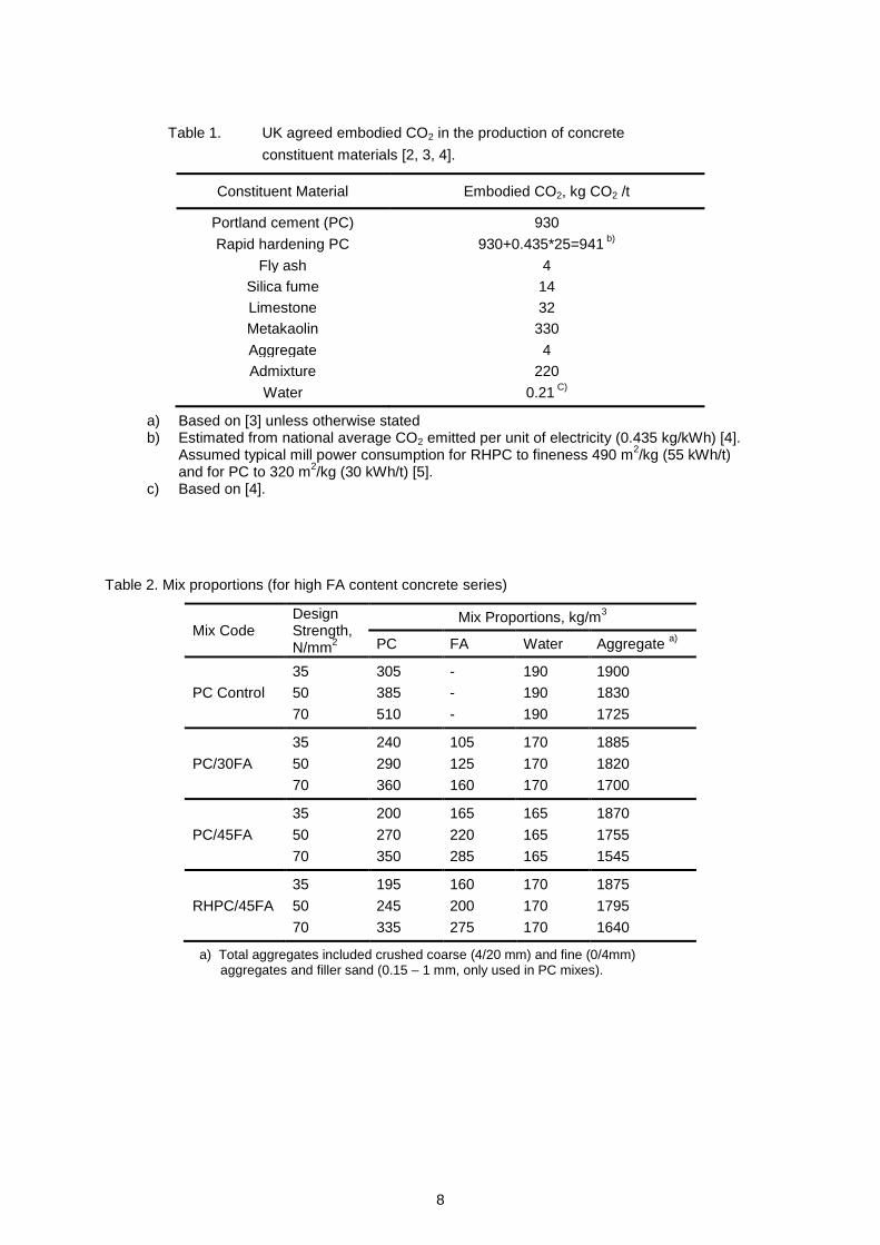
The levels of embodied CO2 in the production of concrete constituent materials have recently been
enumerated in the UK, with the values agreed given in Table 1 [2-5]. Given this, it is now possible to
control the level of CO2 in a wide-range of concrete products from RC structural elements, through to

2
aerated concrete blocks. However, it is important that this is carried out in a rational and objective
manner, through which the technical performance requirements for the applications are maintained.
It is important to recognise that where several performance requirements apply, a balance of the
constituents in concrete mixes may be required and even the construction process adjusted to meet
them and best utilise the benefits of FA. In other words, modification beyond straight replacement of
FA may be necessary. This paper addresses these issues in more detail by examining the resistance
of fly ash concrete to chloride ingress and carbonation, both directly and in terms of lowest practicable
embodied CO2. Data is presented from studies considering, (i) high FA contents, (ii) FA ternary
cement combinations and (iii) coarse FA materials.
2 High FA Content Concrete
High FA content in this paper refers to concrete where the material is used as a cement component at
levels beyond 30%, commonly adopted in structural concrete [6]. In some situations, concrete mixes
containing more than 50% FA by mass of the cementitious material have been used [7]. Furthermore,
current European standards allow a maximum FA level of 55% by mass [8, 9]. The results presented
here cover mixes with FA up to 45% by mass. One of the issues associated with this is that low early
strengths may result, which can have implications for the construction process in terms of formwork
striking times.
2.1 Materials and Mix Proportions
The main characteristics of the cements and addition used in this study are given in Reference 6.
RHPC was used to control the early strength of concrete with high FA contents to match those
containing PC-only. The concretes contained crushed single-size coarse aggregate (maximum size
20mm) and a crushed sand, with a fine filler also included in the PC control mixes. The mix
proportions for the concretes are given in Table 2.
The water contents of these were controlled to achieve the target slump range of 60 to 90 mm and the
w/c ratio adjusted to give strengths of 35, 50 and 70 N/mm2. FA was included with PC at levels of 30
and 45%, with the latter also being combined with RHPC. All of the test concretes were cured in water
at 20°C to 28 days, prior to pre-conditioning / testing.
2.2 Durability Performance
Chloride diffusion and accelerated carbonation (4% CO2, 55% RH) tests were carried out following the
methods described by Dhir et al [10, 11].
The coefficient of chloride diffusion for PC, PC/30FA , PC/45FA and RHPC/45FA concretes are given
in Fig. 1. The results generally agree with behaviour noted previously for FA concretes, indicating
significantly lower diffusion coefficients for these than PC concretes, when compared on an equal
strength basis. In addition, the 45% FA content concretes had lower coefficient values than those with
30% FA.
A comparison between the depths of accelerated carbonation for these concretes following 10 and 20
weeks exposure is made in Fig. 2. As indicated, these were generally greater for FA concretes than
those of PC at equal strength, with differences tending to increase at higher FA level, for 35 and
50 N/mm² but similar values noted at 70 N/mm².

3
2.3 Embodied CO2
The concretes were evaluated for embodied CO2 of their constituent materials. Table 1 shows the
values used in the comparisons, which are mainly based on information given by the UK concrete
industry.
Fig. 3 compares the calculated embodied CO2 of the concretes. The inclusion of FA lead to
reductions in this compared to PC and, as might be expected, and the effect increased with FA level.
With RHPC used instead of PC, similar values / slight reductions in embodied CO2 were noted
(reflecting minor reductions in RHPC/FA contents in these concretes).
3 FA Ternary Cement Combinations
In this research, various additions, including FA, limestone (LS), metakaolin (MK) and silica fume (SF)
were used with PC. The FA content of the concretes ranged from 20 to 55%, covering that given in
current standards [8, 9], and the mixes were considered at equal w/c ratio. Interpolation was used to
obtain the mix proportions for a given strength and to enable embodied CO2 to also be compared on
this basis.
3.1 Materials and Mix Proportions
The characteristics of the PC and four additions used have been given previously [6]. The concretes
contained natural gravel in two fractions (4/10mm and 10/20mm) and a medium grade sand.
The concretes had a free water content of 165 l/m3 with a high-range water-reducing admixture used
to give a slump in the range of 60 to 90 mm. The w/c ratios were 0.35, 0.50 and 0.65, selected to
cover the practical range. FA was used at levels of 20, 35 and 55% and then 10% of the FA at 35%
was replaced with each of the other additions. Curing of concrete was carried out in water at 20ºC for
the required period, prior to pre-conditioning / testing.
3.2 Durability Performance
Chloride migration tests were carried out following the NT Build 492 method [13]. The effect of the
test concretes on non-steady state migration of chloride at 0.50 w/c ratio is shown in Fig. 4. The data
indicate that this reduced with increased curing time (28 and 90 days) in all cases.
The FA binary concretes gave lower migration compared to PC and this increased with FA level. The
effect of FA on chloride ingress is similar to that shown in Fig. 1, despite differences in the basis of
comparison (strength and w/c ratio). The inclusion of second additions, MK, SF or LS, further reduced
chloride migration.
The accelerated carbonation depth [11] was found to increase with FA in concrete compared to the
PC reference and the effect became greater at higher FA levels. The inclusion of second additions
gave increases in carbonation depth compared to the binary concrete, except for LS where there was
a slight reduction. The results reflect the effect of the materials on the concrete chemistry and
microstructure and suggest the former has the greater influence on the process.
The behaviour for carbonation was different to that noted for chloride migration, which indicates that
where more than one processes can occur, a balance would be necessary in material selection to
optimise performance.

4
3.3 Embodied CO2
In evaluating embodied CO2, the concretes described above and those of a related study [14] were
included and the following approaches to mix proportioning considered:
a) equal w/c ratio of 0.5 with a fixed water content of 165 l/m³
b) equal 28 day cube strength with a fixed water content of 165 l/m³
c) equal 28 day strength with a variable water content and fixed water-reducing admixture
content (0.6% by weight of cement plus additions)
These were examined to identify the role that factors associated with concrete mixes and basic
properties have on embodied CO2 and the results are given in Fig.5. The use of FA in concrete,
particularly at high levels, gave reductions in embodied CO2 compared to PC. The rate was
influenced by how the concretes were proportioned, with greatest reductions obtained for comparisons
at equal w/c. At equal strength, the reduction was less significant with fixed water content (variable
water-reducing admixture), than when the water content was allowed to vary (ie fixed water-reducer
content).
The inclusion of a second addition gave minor differences, which again depended on the concrete
proportions. This however, had a significant reduction in chloride migration (Fig. 4). Therefore, the
advantage of using ternary mixes can be seen when the comparison is based on equal chloride
resistance.
4 Coarse Fly Ash
The European Standard for FA, BS EN 450-1 [15], permits the use of material up to a fineness of 40%
retained on a 45μm sieve. This represents a wider property range than has been traditionally used in
the UK for FA as a cement component. Work examining material from single and multiple sources
indicates that reductions in strength may occur with increasing fly ash coarseness [16].
In this study, minor adjustments to the concrete mixes through the w/c ratio were considered to take
account of the effect of FA fineness and achieve equal strength.
4.1 Materials and Mix Proportions
A PC and four FAs with different fineness (45μm sieve retention = 3.5, 13.5, 27.0 and 35.0%) and
similar LOI values (between 3.5 – 5.5%) were used, see Reference 16. The aggregates were similar
to those used in the ‘high FA content concrete’ research (Section 2). The concrete mix constituent
proportions, adjusted as indicated above, are given in Table 3. A FA level of 30% was used and
curing of the test concretes was as described for the other test series above.
4.2 Durability Performance
The coefficient of chloride diffusion and the depths of accelerated carbonation following 10 and
20 weeks exposure [10, 11] for PC/FA concretes of strength 35 N/mm², with different FA fineness are
compared in Fig. 6. The results indicate similar general trends to those noted above between PC and
the various FA concretes considered. With small adjustments to the concrete mix constituent
proportions to achieve the same strength, the variations in FA fineness between 3.5 to 35.0% gave
only minor effects on the durability in terms of chloride diffusion and accelerated carbonation.

5
4.3 Embodied CO2
Fig. 7 compares the calculated embodied CO2 of the concretes. It was assumed for FA that this did
not change with the variation in fineness.
Therefore, the four FA concretes essentially gave similar embodied CO2 at the same strength (with
only minor differences in the concrete mix proportions). As with the data shown in Figs. 3 and 5, the
inclusion of FA lead to reductions in embodied CO2 compared to PC and this effect increased with
strength.
5 Balancing Durability Performance and Sustainability
With increasing consideration being given to sustainability, optimising materials to meet several
requirements is becoming increasingly important. Given the performance effects noted above,
different concretes would be appropriate when optimising for chloride exposures, compared to those
for carbonation.
In order to demonstrate how the approach to material selection could be carried out, taking account of
embodied CO2, two exposure classes covering corrosion due to chlorides from seawater (XS3) and
carbonation (XC3/4) were considered. The minimum requirements for concrete exposed to XS3 (for
nominal cover depth 50mm+Δc) and XC3/4 conditions (for nominal cover depth 30mm+Δc) are given
in Table 4 (50 years’ service). Options for meeting these based on the ‘FA ternary cement
combinations’ research are considered in the following sections.
5.1 Chloride Exposure Conditions
Table 5 gives compressive strength, chloride resistance and embodied CO2 for concretes with FA
levels up to 55%, and could be used in structures exposed to a marine environment. The minimum
requirements for the specification and the ‘limiting factors’ which are controlling are indicated for each
concrete.
The binary concretes indicate that the 55% FA concrete gives the ‘best’ performance in terms of
chloride resistance and embodied CO2. When ternary combination concretes are used, chloride
resistance can be further improved, while embodied CO2 is similar to the FA binary concretes at the
same level. In this case the 45%FA/10%SF concrete had the ‘best’ performance.
5.2 Carbonation Exposure Conditions
Table 6 makes a similar comparison for carbonation to that for chloride ingress above. This indicates
that cement combinations with lower embodied CO2 had greatest carbonation depths. Thus in the
case of carbonation environments, a balance would have to be made, such as reducing the w/c ratio
(which could increase cost) and/or increasing the depth of cover (which could affect structural
performance).
A weighting factor method [17] is considered as a pragmatic route to balancing durability and
embodied CO2. A weighted objective function, h(F(x)), can be established as follows:
)()())(( 22 xxxF COCOCarbCarb fwfwh
where: wCarb is the weighting factor for carbonation performance, 0 wCarb 1
wCO2 is the weighting factor for embodied CO2, 0 wCO2 1, and wCarb + wCO2 = 1

6
fCarb(x) is the normallised carbonation value
fCO2(x) is the normallised embodied CO2, and
x is a set of the cement combinations in consideration.
Assuming equal consideration for carbonation and embodied CO2, i.e. wCarb = wCO2 = 0.5, the minimum
h value is obtained with the ternary mix, 45%FA/10%LS, when the figures in Table 6 are considered.
This suggests that the ternary cement combinations with LS as a second addition could be an option
to balance carbonation resistance and embodied CO2. It should be noted that this result depends on
the weighting factor and if this is changed, depending on specific requirements, a different result would
be obtained.
6 Concluding Remarks
As the demands on low carbon and carbon-critical design intensify, so there is an increasing need to
look to a range of material options. Given its wide availability and environmental credentials, FA has
significant potential in this role. However, with ever greater demands, balancing of these may be
necessary to optimise performance.
The research described has highlighted the importance of how FA is used. In general, best
performance with the material was obtained when concrete was designed at equal 28 day strength.
For example, when this was followed, there was little effect of different FA properties on durability.
Similarly, in the case of chloride, increasing FA content, or the use of ternary cements gave enhanced
performance, however, the opposite was found for carbonation.
In terms of embodied CO2, this tended to mirror the material effects notes for chloride ingress, while
again, the opposite tended to occur with carbonation. The implication of this is, with increased
chloride resistance, good environmental performance may be expected however, with carbonation a
balance between this and the environmental requirements would need to be considered in optimising
concrete. This may also apply if chloride/carbonation and embodied CO2 were to be considered.
The work, therefore, provides an indication of how both durability and sustainability can be considered
collectively. However, it was noted that some of the concretes extended the time to achieve early
strength, particularly with high FA contents, which may have implications for formwork removal and
this factor may also need to be considered in the material selection process.
7 Acknowledgements
The data reported in this study is based on information provided from several research projects. The
authors would like to acknowledge the contribution made to these by CTU staff and postgraduate
students in collaboration with industrial partners, the Mineral Products Association: Cement and
Concrete and the United Kingdom Quality Ash Association.
References
[1] Meissner H S, Pozzolans Used in Mass Concrete, ASTM STP 99:pp.16-30, 1949
[2] British Cement Association. Fact Sheet 18 [Part 1] Embodied CO2 of UK cement, additions
and cementitious material, 2009.
7
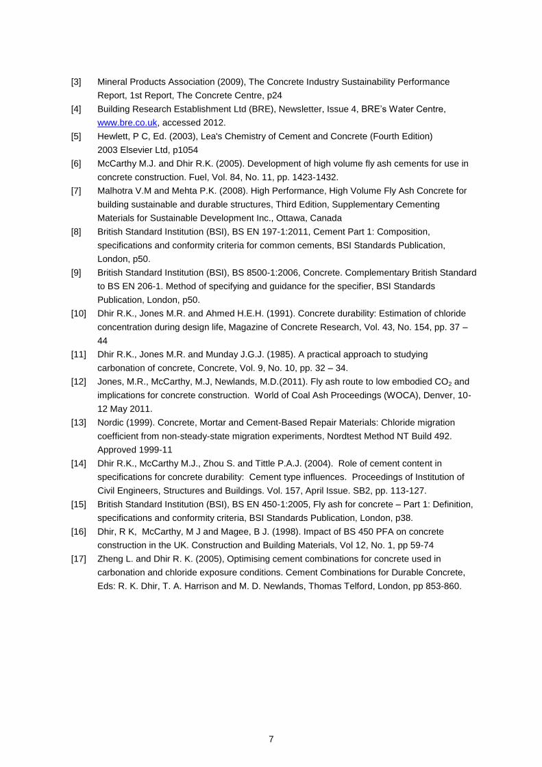
[3] Mineral Products Association (2009), The Concrete Industry Sustainability Performance
Report, 1st Report, The Concrete Centre, p24
[4] Building Research Establishment Ltd (BRE), Newsletter, Issue 4, BRE’s Water Centre,
www.bre.co.uk, accessed 2012.
[5] Hewlett, P C, Ed. (2003), Lea's Chemistry of Cement and Concrete (Fourth Edition)
2003 Elsevier Ltd, p1054
[6] McCarthy M.J. and Dhir R.K. (2005). Development of high volume fly ash cements for use in
concrete construction. Fuel, Vol. 84, No. 11, pp. 1423-1432.
[7] Malhotra V.M and Mehta P.K. (2008). High Performance, High Volume Fly Ash Concrete for
building sustainable and durable structures, Third Edition, Supplementary Cementing
Materials for Sustainable Development Inc., Ottawa, Canada
[8] British Standard Institution (BSI), BS EN 197-1:2011, Cement Part 1: Composition,
specifications and conformity criteria for common cements, BSI Standards Publication,
London, p50.
[9] British Standard Institution (BSI), BS 8500-1:2006, Concrete. Complementary British Standard
to BS EN 206-1. Method of specifying and guidance for the specifier, BSI Standards
Publication, London, p50.
[10] Dhir R.K., Jones M.R. and Ahmed H.E.H. (1991). Concrete durability: Estimation of chloride
concentration during design life, Magazine of Concrete Research, Vol. 43, No. 154, pp. 37 –
44
[11] Dhir R.K., Jones M.R. and Munday J.G.J. (1985). A practical approach to studying
carbonation of concrete, Concrete, Vol. 9, No. 10, pp. 32 – 34.
[12] Jones, M.R., McCarthy, M.J, Newlands, M.D.(2011). Fly ash route to low embodied CO2 and
implications for concrete construction. World of Coal Ash Proceedings (WOCA), Denver, 10-
12 May 2011.
[13] Nordic (1999). Concrete, Mortar and Cement-Based Repair Materials: Chloride migration
coefficient from non-steady-state migration experiments, Nordtest Method NT Build 492.
Approved 1999-11
[14] Dhir R.K., McCarthy M.J., Zhou S. and Tittle P.A.J. (2004). Role of cement content in
specifications for concrete durability: Cement type influences. Proceedings of Institution of
Civil Engineers, Structures and Buildings. Vol. 157, April Issue. SB2, pp. 113-127.
[15] British Standard Institution (BSI), BS EN 450-1:2005, Fly ash for concrete – Part 1: Definition,
specifications and conformity criteria, BSI Standards Publication, London, p38.
[16] Dhir, R K, McCarthy, M J and Magee, B J. (1998). Impact of BS 450 PFA on concrete
construction in the UK. Construction and Building Materials, Vol 12, No. 1, pp 59-74
[17] Zheng L. and Dhir R. K. (2005), Optimising cement combinations for concrete used in
carbonation and chloride exposure conditions. Cement Combinations for Durable Concrete,
Eds: R. K. Dhir, T. A. Harrison and M. D. Newlands, Thomas Telford, London, pp 853-860.
8
Table 1. UK agreed embodied CO2 in the production of concrete
constituent materials [2, 3, 4].
Constituent Material Embodied CO2, kg CO2 /t
Portland cement (PC) 930
Rapid hardening PC 930+0.435*25=941 b)
Fly ash 4
Silica fume 14
Limestone 32
Metakaolin 330
Aggregate 4
Admixture 220
Water 0.21 C)
a) Based on [3] unless otherwise stated b) Estimated from national average CO2 emitted per unit of electricity (0.435 kg/kWh) [4].
Assumed typical mill power consumption for RHPC to fineness 490 m2/kg (55 kWh/t)
and for PC to 320 m2/kg (30 kWh/t) [5].
c) Based on [4].
Table 2. Mix proportions (for high FA content concrete series)
Mix Code Design Strength, N/mm
2
Mix Proportions, kg/m3
PC FA Water Aggregate a)
35 305 - 190 1900
PC Control 50 385 - 190 1830
70 510 - 190 1725
35 240 105 170 1885
PC/30FA 50 290 125 170 1820
70 360 160 170 1700
35 200 165 165 1870
PC/45FA 50 270 220 165 1755
70 350 285 165 1545
35 195 160 170 1875
RHPC/45FA 50 245 200 170 1795
70 335 275 170 1640
a) Total aggregates included crushed coarse (4/20 mm) and fine (0/4mm) aggregates and filler sand (0.15 – 1 mm, only used in PC mixes).

9
Table 3. Mix proportions (for study of effects of coarse fly ashes)
Mix Code Design Strength, N/mm
2
Mix Proportions, kg/m3
w/c ratio
WR Dosage,
% of cement
PC FA Water Aggregate
PC Control
25 225 - 175 1985 0.77 -
35 270 - 175 1945 0.65 -
50 370 - 175 1850 0.47 -
60 450 - 175 1765 0.38 -
PC /30FA1
(45μm ret. = 3.5%)
25 190 85 165 1950 0.60 0.55
35 230 95 165 1910 0.51 0.55
50 295 125 165 1820 0.39 0.66
60 350 150 165 1745 0.34 0.88
PC /30FA2
(45μm ret. = 13.5%)
25 190 85 160 1970 0.58 0.99
35 230 95 160 1925 0.49 0.99
50 295 125 160 1830 0.38 1.10
60 350 150 160 1755 0.32 1.32
PC /30FA3
(45μm ret. = 27.0%)
25 190 85 160 1970 0.58 0.99
35 230 95 160 1925 0.49 0.99
50 295 125 160 1830 0.38 1.10
60 350 150 160 1755 0.32 1.32
PC /30FA4
(45μm ret. = 35.0%)
25 190 85 155 1980 0.56 1.43
35 230 95 155 1935 0.47 1.43
50 295 125 155 1840 0.36 1.65
60 350 150 155 1765 0.31 1.65
Table 4. Concrete requirements for XS3 (chloride) and XC3/4 (carbonation) exposure classes as
specified in BS 8500 for 50 years of design life for different cement combinations.
FA Content,
% by Mass
Concrete Requirements
Minimum Strength Class
Maximum w/c Ratio
Minimum Cement Content, kg/m
3
Limiting Factors for XS3 Chloride Exposure (nominal cover depth 50mm+Δc)
6-20 C50 0.40 380
21-35 C35 0.50 340
36-55 C30 0.50 340
Limiting Factors for XC3/4 Carbonation Exposure (nominal cover depth 30mm+Δc)
6-35 C35 0.60 280
36-55 C37 0.55 300

10
Table 5. Comparison of embodied CO2 of concretes subjected to chloride-induced corrosion (XS3).
Cement
Combination
Minimum Concrete Requirements for XS3 Exposure
Concrete Properties
Minimum Strength, N/mm
2
Maximum w/c Ratio
Min Cement Content,
kg/m3
28 day Cube Strength, N/mm
2
Chloridea)
Migration,
×10-12
m2/s
Embodied CO2, kg/m
3
Concreteb)
100%PC 50 0.40 c) 380 66 28.0 391
PC/20FA 50 0.40 c) 380 61 23.7 315
PC/35FA 35 c) 0.50 340 35 27.1 212
PC/55FA 30 c) 0.50 340 30 20.0 181
PC/25FA/10SF 35 0.50 340 c)
48 5.4 212
PC/25FA/10LS 35 0.50 340 c)
40 10.9 212
PC/25FA/10MK 35 0.50 340 c)
38 9.8 223
PC/45FA/10SF 30 0.50 340 c)
35 4.9 149
PC/45FA/10LS 30 c) 0.50 340 30 8.3 170
PC/45FA/10MK 30 c) 0.50 340 30 7.5 166
a) NT Build 492 test b) Calculations based on data in Table 1. c) Limiting factor(s) controlling the specification.
Table 6. Comparison of embodied CO2 of concretes subjected to carbonation-induced corrosion
(XC3/4).
Cement Combination
Minimum Concrete Requirements for XC3/4 Exposure
Concrete Properties
Minimum Strength, N/mm
2
Maximum w/c
Ratio
Min Cement Content,
kg/m3
28 day Cube Strength, N/mm
2
8 Week Accelerated
Carbonation a)
Depth, mm
Embodied CO2, kg/m
3
Concrete b)
100%PC 35 0.60 280 c)
41 11.5 268
PC/20FA 35 0.60 280 c)
36 18.5 216
PC/35FA 35 c)
0.60 280 35 18.5 209
PC/55FA 37 c)
0.55 300 37 22.5 198
PC/25FA/10SF 35 c)
0.60 280 c)
35 31.0 178
PC/25FA/10LS 35 c)
0.60 280 35 17.0 194
PC/25FA/10MK 35 c)
0.60 280 35 23.5 211
PC/45FA/10SF 37 c)
0.55 300 37 33.5 214
PC/45FA/10LS 37 c)
0.55 300 37 19.0 182
PC/45FA/10MK 37 c)
0.55 300 37 28.0 191
a) 4% CO2, 55% RH, 20°C b) Calculations based on figures in Table 1. c) Limiting factor(s) controlling the specification.

11
Fig. 1 Comparison of coefficient of chloride diffusion for PC, conventional FA and high FA content
concretes.
Fig. 2 Comparison of depth of accelerated carbonation for PC, conventional FA and high FA content
concretes.

12
Fig. 3 Comparison of embodied CO2 of constituent materials for PC, conventional FA and high FA
content concretes.
Fig. 4 Comparison of non-steady state chloride migration and accelerated carbonation test results of
FA binary and ternary concretes

13
Fig. 5 Embodied CO2 of constituent materials of PC, FA binary and ternary concretes.
Fig. 6 Comparison of coefficient of chloride diffusion and depth of accelerated carbonation of PC/FA
concretes with different FA fineness.
5
10
15
20
25
30
5
8
11
14
17
20
CEM I FA3.5 FA13.5 FA27.0 FA35.0
Co
effi
cien
t o
f C
olo
rid
e D
iffu
sio
n, c
m2 /
s×1
0-9
Dep
th o
f A
ccel
erat
e C
arb
on
atio
n, m
m
10 weeks accelerate carbonation
20 weeks accelerate carbonation
Chloride diffusion
Design strength: 35 N/mm2

14
Fig. 7 Embodied CO2 of constituent materials of PC/FA concretes with different FA fineness.