Embed Size (px)
Citation preview

Using Control Automation to Monitor and Control the Pyrolysis of Peanut Shells
Johnny Mack Devine IIEnergy Research Undergraduate Laboratory Fellowship
Albany State UniversityNational Renewable Energy Laboratory
Golden, CO 80401
August 17,2001
Prepared in partial fulfillment of the requirements of the Department of Science ERULFprogram under the direction of Calvin Feik in the Field Test Laboratory Building at theNational Renewable Energy Laboratory.
Participant:
Signature
Research Advisor:
Signature

Abstract
Using Control Automation to Monitor and Control he Pyrolysis of Peanut Shells intoHydrogen. JOHNNY M. DEVINE II (Albany State University, Albany, Georgia 31705)Calvin Feik (National Renewable Energy Laboratory, Golden, Colorado 80401).
Petroleum resources in the world today are diminishing as fast as they are beingproduced; the answer to this is biomass. By performing a process by the name ofpyrolysis you can break the biomass down into hydrogen and other gases. The processsof pyrolysis requires the use of many machines and pieces of equipment that need to bemonitored and controlled some kind of way. The program Opto 22 Factory Floor is usedto monitor and control the process. This program uses a PC with Windows 95 or NT torun the machinery. Opto 22 Factory Floor does not require the user to know anyparticular programming language. This program is one of the most widely used controlautomation software tools in the market today. It is by far easier to use that the UNIXsystem that was previously in use in the TCUF. The machinery that uses a nickel basecatalyst to perform pyrolysis on the biomass is not yet designed. Also the equipment usedto measure the percent output of gases needs to be redesign all on this Opto 22 FactoryFloor program. With this the equipment will be able to be used more efficiently and alsobe easily transported to the test site in Georgia.
Research CategoryERULF: Physics Chemistry Biology Engineering Computer Science Other_____
CCI: Biotechnology Environmental Science Computing
TYPE ALL INFORMATION COMPLETELY AND CORRECTLY
School Author Attends: Albany State UniversityDOE National Laboratory Attended: National Renewable Energy LaboratoryMentor’s Name: Calvin FeikPhone: (303) 384-6142Email address: [email protected]
Presenter’s Name: Johnny M. Devine IIMailing Address: 119 Patrol DriveCity/State/Zip: Albany, GA 31705Phone: (229) 883-5694E-mail Address: [email protected]

Table of Contents
Abstract iii
Introduction 1-3
Methods and Materials 4-7
Results 6-7
Discussion and Conclusion 7
Acknowledgments 7
References 8
Tables 9-12

Devine 1Introduction
In today’s society, traditional resources for energy are either becoming scarce and
causing prices to rise or are too harmful to the environment. This is seen today with the
increasing cost of gasoline and other petroleum products. With increasing demand and
decreasing supply makes it a must that researchers find an alternative fuel to supplement
or replace the withering supply of oil. The production of renewable hydrogen could be
the solution. The production of hydrogen by the processing of pyrolysis products that are
byproducts of activated carbon is one path that could be demonstrated in the near future.
The concept is based on producing hydrogen from biomass oils in conjunction with other
products that have greater value and can reduce the cost of hydrogen. The original idea
was that the pyrolysis oil could be separated into two parts based on water solubility. The
water-soluble fraction is to be used for hydrogen production and the water insoluble
fraction could e used in adhesive formulation (Kelley et al., 1997). Although this option
remains viable, commercial deployment opportunities for the hydrogen linked to the
adhesive coproducts are not in the near future. Therefore alternatives had to be developed
based on the coproduct strategy. The conversion of biomass to activated carbon is another
route to hydrogen with a valuable coproduct. In the first of activated carbon process slow
pyrolysis is used to maximize the yield of charcoal and organic vapors that are produced
as a by-product.
The process, which is by computer controlled, involves making activated carbon
from densified peanut shells. The computer control system that is being used for the
TCUF is Opto 22 Factory Floor. Opto 22 automation products are used in every industry
Devine 2
where process control is critical, from agriculture to aerospace. Dairy farmers use Opto
22 components to control milk processing and elevator manufactures use controllers by
the hundred. This program allows a user to control and monitor the entire plant and take
corrective measures from a computer in real time, meaning that it is happening when you
see it. This program allows for a user to see real time data from the factory floor in the
form of graphs or bitmaps that he or she can create. This is done by connecting points in
the TCUF to a controller, which is then relayed to the computer program. In the TCUF
there are two controllers Mistic I and Mistic II that every point must be connected to.
Each controller consists of bricks, which contain 16 I/O points each. I/O points are
objects that are out in the plant that collect data or are used to input data, such as
temperatures or flow rates. (Control for the cart that measures the flow rate of gases that
passes through the plant.)
Also in the TCUF is a two-inch reactor that has a Molecular Beam Mass
Spectrometer (MBMS) this is just a smaller scale of what is going on with the * inch
reactor. The difference in the two is that the two-inch reactor is only testing to see what is
happening to the biomass at the different temperatures along the process of turning it into
hydrogen, that is the purpose of the MBMS. The two process also uses a computer
control except that it is not as of an advanced program meaning that it wasn’t design to
handle as many points that are in the eight-inch reactors process.
Pyrolysis also can be done on a small scale and not just in a factory. One example
is found on a small island in the Philippines. There scientists and researchers have taken a

Devine 3
small version of the process and incorporated it into people’s lives, by using coconut
shells to form energy from hydrogen. Now the small island has power to run radios and
equipment for weaving, and this is raising their standard of living. Soon the island will
be able to trade with other islands and prosper.
The process that is being tested in the TCUF is going to be shipped to an
industrial site in Blakely, Georgia for Phase II testing. Southwest Georgia was identified
as an excellent opportunity because of the importance of agriculture and the need for zero
emission transportation fuels in the Atlanta area. Scientific Carbons Inc. in Blakely,
Georgia uses palletized peanut shells as the feed material for the production of activated
carbon. This will be used as the development site. A slipstream of pyrolysis vapors
produced in the 100 kg/hr continuous pyrolysis unit will be used fort the long duration
steam reforming test. This will hopefully work well enough to be able to proceed with
Phase III of the research. Phase III of the research consist of using the hydrogen produced
from the Blakely shelling plant and power a bus in the nearby city of Albany, Georgia, on
the campus of Albany State University for. This integrated strategy will demonstrate the
potential impact of hydrogen and bioenergy on the development and diversification of
rural areas.
Materials and Methods
Placing Points in OptoControl
For a piece of equipment to be controlled through Opto 22 the points must be
placed in OptoControl. OpoControl is where every point is with a description, module

Devine 4
number, location in controller, and which controller contains it. OptoControl is also
where the points are given assignments or specifications as to what their duty is whether
it is read data or send data. Points for the new reformer where to placed in OptoControl in
Mistic I brick 107. Although brick 107 already has two points there, those two points
were to be placed in brick 105 and the new points would occupy all of brick 107. The
first step in wiring a controller is to make sure that there is no power running through the
controller. Once the proper precautions have been done to make sure that there is no
power being transmitted through the wires, the connection of the points takes place.
When connecting the wires you run it from the specified brick to the proper power
connector. Once all points are connected then the cover of the brick is replaced and
power is turned back on.
Designing the Controls for the GC Analytical Cart
Designs for the GC Analytical Cart are being placed on Opto 22 due to the fact
that the UNIX, The system that the controls were previously on, cost too much money to
maintain. The UNIX system is a system that is not as user friendly or easily learned, so
for this purpose of having to transport and teach to new workers Opto 22 is used. When
designing a new control for a piece of equipment the first task is to open a new window
and to give it a name. The name that will be given to this window is GC Analytical. With
this step you can design the equipment in Opto 22 or design it on another design software
and import it onto Optp22 as a bitmap. The designs for the GC Analytical Cart are done
in Opto 22 Configuration mode. Since an operating system for the cart had been designed
in the UNIX system, which is the old control automation for the TCUF, the design in the

Devine 5
Opto 22 was made to look similar to that of the UNIX. Once the design is placed on the
new window points must now be inserted so that the new windows connects to the device
it represents.
Designing Controls for the Reformer
Designing controls for the reformer consisted of copying and pasting a previous
design. Since the reactor and the reformer had the same basic design the image that was
being used for the reactor is copied and pasted onto the new reformer window. Once the
reformer was there the design for the piping had to be placed in the window. Once all the
piping was is and the points placed in their respective places the controls for the reformer
will be complete.
Instaling the GC Analytical Cart
The GC Analytical Cart consists of many instruments. The First instrument that
needs to be placed in the cart was the flow gauge. Its position is at the top of the cart so it
is the first to be placed in the cart. This next piece of equipment is the paramagnetic
oxygen sensor, which measures the percent of oxygen that is in the final product of gases.
The next two pieces of equipment are the NDIR or Nondispersive infrared sensors. These
two black boxes read the percent of carbon monoxide (CO), carbon dioxide (CO2), and
methane (CH4) that are in the final product of gases. Once all these have been placed in
the cart two gas chromatography units are put in the cart. The use of two is required so if
one of the units happens to stop working the other could be substituted with out a
Devine 6
problem. These two units read at which point the gases separate from each other. Once all
the instruments that read data are placed in the cart securely the piping is done. Piping is
done so that the gases may be transported into the cart and from one instrument to
another. Piping is done with five types of tubing; quarter inch inner diameter Teflon and
stainless tubing, eighth inch inner diameter Teflon stainless tubing, and eighth inch inner
diameter copper tubing.
Results
Producing hydrogen as a by-product of biomass seems to be the best alternative to
petroleum products. The only key factors are being able to produce the hydrogen in the
large scale for a period of time and to be able to do it a competitive price with other
forms of fuel. Also the Opto 22 seemed to be the best control automation software to use
being that this facility will be transported down to Georgia. So the overall thought of
producing hydrogen, this seems to be the best alternative overall of a renewable fuel. No
test had been run yet in the TCUF with any of the equipment that was designed on Opto
22 Factory Floor software. Test will not begin until the following week in which I will
not be here.
Discussion and Conclusion
The Opto 22 Factory Floor program seemed to be the most user-friendly control
automation software being since the UNIX system uses the C programming language
which gets to be very difficult when modifying a project. Also with the C programming

Devine 7
language one set of commands can delete all your work with no undo button or back
button to correct your mistake. Also along with the fact that Opto 22 works with any
computer with Windows 95 or better it is a program that takes little more that the
purchase of the software and bricks to be up and running.
Acknowledgments
I would like to start off by thanking the United States Department of Energy, the
National Renewable Energy Laboratory for taking the time out to concentrate on finding
renewable energies like they are doing at NREL. Energy Research Undergraduate
Laboratory Fellowship and American Western Universities Inc. for giving me the
opportunity to come out to Colorado and learn more about renewable energy and a
chance to experience for the first time the Rocky Mountains. I would like to thank Linda
Lung and Robi Robichaud for their guidance given to me while in Colorado. I also would
like to thank Bob Evans and everyone involved with the TCUF for his or her help and
guidance with my project this summer.

Reference
About Opto 22: Connecting You to the Real-World. (n.d.). Retrieved August 3, 2001, from http://www.opto22.com/home/index.asp
Baca-Overly, C. 2001. “Assembly, Operation, and Controls of GC Analytical Cart.” Personal Communication.
Chornet, E., S. Czernik, D. Wang, C. Gregoire, M. Mann. 1994. “Biomass to Hydrogen via Pyrolysis and Reforming. In Proceedings of the 1994 DOE/NREL Hydrogen Program Review, 407-432. Livermore, California, NREL/CP-470-6431; CONF- 9404194.
Czernik, S., R. French, C. Feik, E. Chronet. 2001. “Hydrogen form Biomass-Derived Liquids.” In Proceedings of the 2001 DOE/NREL Hydrogen Program Review, Baltimore, MD.
French, R. 2001. “Assembly, Operation, and Controls of GC Analytical Cart.” Personal Communication.
UNIX: History and Timeline. (n.d.). Retrieved August 3, 2001, from http://www.unix- systems.org/what_is_unix/history_timeline.html
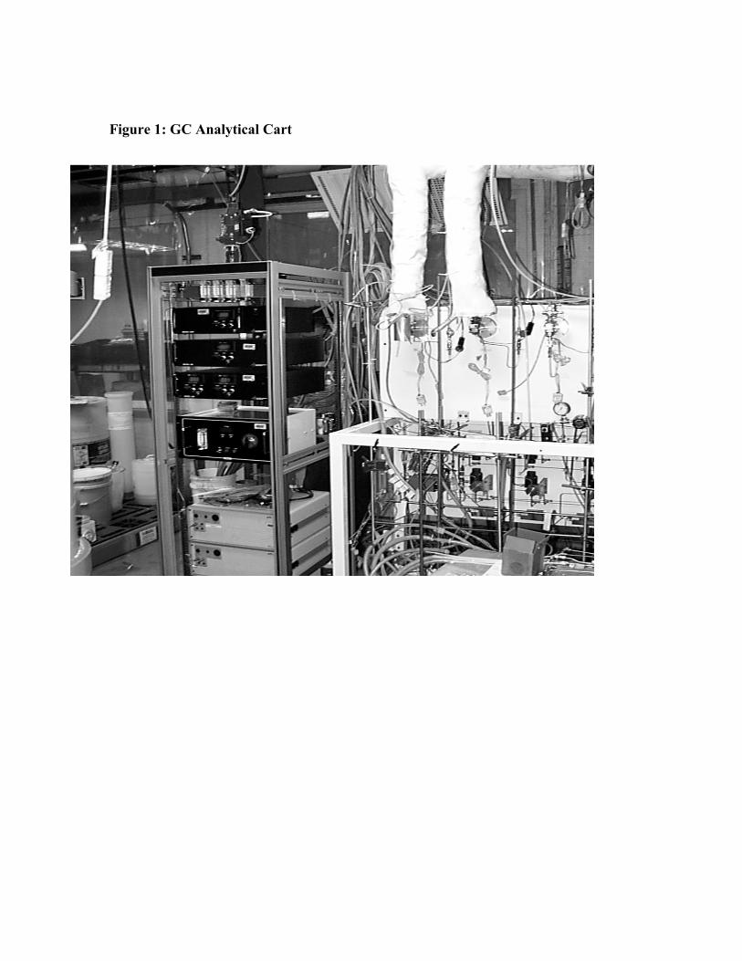
Figure 1: GC Analytical Cart

Figure 2: UNIX Work Station

Figure 3: Opto 22 Factory Floor Control System

Figure 4: Mistic I and Brick 107