Embed Size (px)
Citation preview

1 © 2011 HETRONIC Swiss AG www.hetronic.ch
User’s Manual
HETRONIC Swiss AG Altgraben 23 4624 Härkingen Tel.: +41 (0)62 388 99 20 Fax.: +41 (0)62 388 99 29

2 © 2011 HETRONIC Swiss AG www.hetronic.ch
Using the Radio Control is forbidden for anybody wh o has not read and fully understood this manual. Special attention should be to given t he safety instructions herein contained. All reproduction rights, either through photocopies or computer means or supports, are reserved. All texts, illustrations, and drawings are the propriety of HETRONIC and their use can only be granted prior to the formal permission of HETRONIC. The technical features of the Radio Control as described in this Manual may be subsequently modified without notice with the sole purpose of improving the equipment to better satisfy the user.

3 © 2011 HETRONIC Swiss AG www.hetronic.ch
Table of Contents:
1 SAFETY 1.1 S a f e t y o f R a d i o C o n t r o l S y s t e m s 1.2 S a f e t y I n f o r m a t i o n 1.3 A u t h o r i z e d O p e r a t o r s 1.4 S a f e t y M e a s u r e s t o b e t a k e n w i t h i n t h e w o r k i n g a r e a 1.5 P r o t e c t i o n D e v i c e s 1.6 H o w t o r e a c t a n d b e h a v e i n c a s e o f a n E m e r g e n c y
2 OPERATION 2.1 B a t t e r y Use 2.2 T h e b a t t e r y c h a r g e r a n d r e - c h a r g e a b l e b a t t e r i e s 2.3 C o n t r o l E l e m e n t s 2.4 V i s u a l C h e ck 2.5 S a f e t y C o n t r o l a n d S t a r t - u p o f t h e R a d i o C o n t r o l 2.6 D i g i t a l F u n c t i o n a n d P r o p o r t i o n a l F u n c t i o n 2.7 O p e r a t i n g p r o b l e m s 2.8 T r o u b l e s h o o t i n g T a b l e 2.9 T h e r a d i o t r a n s m i s s i o n a n d r e c e i v i n g s y s t e m
3 INSTALLATION 3.1 Po s i t i o n i n g t h e r e c e i v e r 3.2 O u t s i d e e l e c t r i c a l c o n n e c t i o n s
4 MAINTENENC
5 DISPOSAL
6 TECHINCAL DATA 6.1 T h e t r a n s m i t t e r i n g e n e r a l 6.2 T h e r e c e i v e r i n g e n e r a l
7 MAP 8 PRODUCT OVERVIEW

4 © 2011 HETRONIC Swiss AG www.hetronic.ch
User’s manual 1 SAFETY 1.1 Safety of the Radio Control System
This Radio Control System has been fitted with electronic and mechanical safety devices. Processing control signals sent by other transmitters is impossible as the transmission codes are totally univocal.
1.2 Safety Information
The use of the Radio Control applied to any machinery allows the operator greater freedom of movement within the working area, improved handling accuracy whilst improving both the efficiency and the safety of the operator. However, all these benefits do require a certain attention from the operator and the staff in charge of maintenance. The correct and safe use of the Radio Control requires the operator to visually follow the remote-controlled machine. It is therefore compulsory that anyone using the transmitting unit stops the Radio Control and removes the starting key from the transmitting unit or the battery from its casing during the break times. The maintenance staff should check that the receiver unit is not powered during the control operations, the change of the battery or the periodic or extraordinary maintenance operations in general. Each Radio Control should be checked at least once a year. Any repair should be made at authorized centers or centers that either QUEST or HETRONIC have recommended or directly at the QUEST or HETRONIC service and spare parts center. Any use of non-original spare parts or tampering by non-authorized staff immediately cancels all the guarantee rights.
1.3 Authorized Operators IMPORTANT !
Always verify the operating instructions of your machine in order to be aware of any further important information to be observed. When placing the transmitter away during the breaks, the user must make sure that no unauthorized people can use it by turning the switch off or removing the key or the battery from its case and locking it in a safe place. In this way, any abusive operations by unauthorized third parties will be prevented. The user must be able to have access to all of the operating instructions that are necessary for the smooth operation of the machine to be controlled. The user must also read and be sure to have understood each section of this manual before using the Radio Control.
1.4 Safety Measures to be taken within the working area The user should ensure that the working area in which the Radio Control will be used is free from any risks for the movement or other potential safety risks. For example, the user should verify that the working area is an area free from any obstacles or dangerous situations that could jeopardize the possibility of operating in total safety.

5 © 2011 HETRONIC Swiss AG www.hetronic.ch
1.5 Protection Devices All of Hetronic’s Industrial Radio Controls have been fitted with an emergency stop push button on the control board of the transmitting unit. Some other protection devices exist in the Radio Control system which automatically intervene whenever: • There is a radio interference in the working area that affects the frequency range of the Hetronic Industrial Radio Control; • The action range of the transmitting unit is exceeded. In the event of the above the radio control immediately activates the Emergency Stop, and interrupts any outgoing signal of the receiving unit whilst maintaining continuous and constant radio contact between the transmitter and receiver. Some radio controls of the HH palm-held series manufactured for small applications have not been fitted with a real emergency stop push-button, unless regulations require it. However, a completely automatic emergency system interrupts the signals and sends the receiving unit into an emergency condition if the transmitter for longer than three seconds has carried out no operations. To quit the state of emergency any it is sufficient to carry out any man oeuvre of the transmitter.
1.6 How to react and behave in case of an Emergency WARNING !
In any Emergency situation, immediately push the Re d Push Button EMERGENCY STOP (also called: EMERGENCY STOP PUSH). Then, follow th e instructions in the machine operating manual.
Unlock stop button by Push-Pull- Stop Momentary Stop Turning clockwise
6 © 2011 HETRONIC Swiss AG www.hetronic.ch
2 OPERATION 2.1 Battery Use
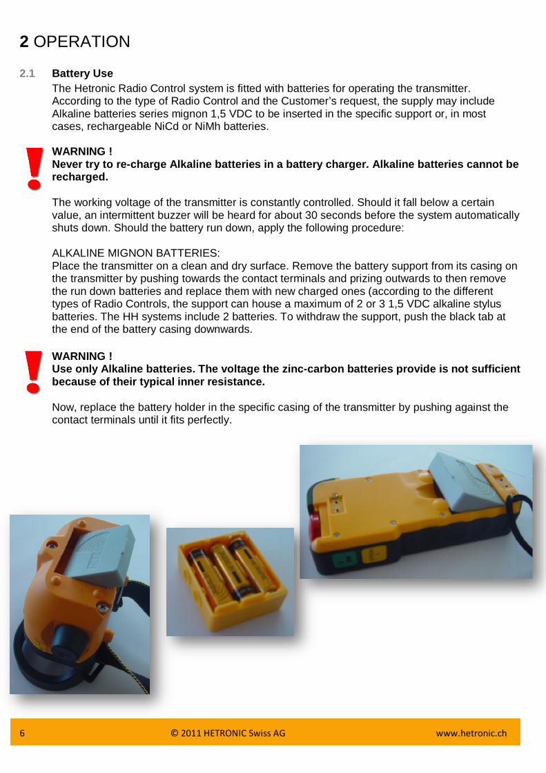
The Hetronic Radio Control system is fitted with batteries for operating the transmitter. According to the type of Radio Control and the Customer’s request, the supply may include Alkaline batteries series mignon 1,5 VDC to be inserted in the specific support or, in most cases, rechargeable NiCd or NiMh batteries. WARNING ! Never try to re-charge Alkaline batteries in a batt ery charger. Alkaline batteries cannot be recharged. The working voltage of the transmitter is constantly controlled. Should it fall below a certain value, an intermittent buzzer will be heard for about 30 seconds before the system automatically shuts down. Should the battery run down, apply the following procedure: ALKALINE MIGNON BATTERIES: Place the transmitter on a clean and dry surface. Remove the battery support from its casing on the transmitter by pushing towards the contact terminals and prizing outwards to then remove the run down batteries and replace them with new charged ones (according to the different types of Radio Controls, the support can house a maximum of 2 or 3 1,5 VDC alkaline stylus batteries. The HH systems include 2 batteries. To withdraw the support, push the black tab at the end of the battery casing downwards.
WARNING ! Use only Alkaline batteries. The voltage the zinc-c arbon batteries provide is not sufficient because of their typical inner resistance. Now, replace the battery holder in the specific casing of the transmitter by pushing against the contact terminals until it fits perfectly.

7 © 2011 HETRONIC Swiss AG www.hetronic.ch
2.2 The battery charge and re-chargeeable batteries Place the transmitter on a clean and dry surface. Remove the run down battery from its casing on the transmitter by pushing towards the contact terminals and prizing outwards to then remove the run down battery and replace it with the new charged one in the battery charger supplied (To remove the rechargeable battery from HH systems, the black tab at the end of the battery casing downwards). Put the replaced run down battery immediately under charge. Check that the battery charger is powered with the lighting up of the Led on the outside. During the recharging of the battery, the outer Led will remain on. It will start blinking as soon as the battery is charged. A sophisticated control system of the battery being charged means the battery under charge can be left for as long as desired. In the HH systems using the VersaPak battery charger, the battery must not be re-charged for more than 24 hours.
WARNING ! Use HETRONIC original spare parts only! If not, the re is the danger of an explosion. Chemical substances that leak or parts that detach themselves can cause irreparable damage.

8 © 2011 HETRONIC Swiss AG www.hetronic.ch
2.3 Control Elements Hetronic manufactures a very wide range of Industrial Radio Controls suitable for just as many applications. Furthermore, Industrial Radio Controls are manufactured according to the specific requests of the Customer or the User. Each radio control can be fitted with many different control elements according to the machine to be controlled, as well as provided with standard controls for its operation, stopping, acoustic warning, start switch, warning led etc… Push buttons, switches, selectors, joysticks and special control accessories complete the radio control and are features of each type. In most cases, the control elements of the Radio Control are arranged in exactly the same way as those on the normal control panel, the only difference being that a machine is started without a cable command.
2.4 Visual Check WARNING !
Always check the sound condition of the transmitter before operating. • Are all of the safety devices in the correct position and in good condition? • Are there any broken parts? • Are all of the rubber protections and the actuator covers sound? • Are all of the connecting plugs and cables sound?
WARNING!
Never work with a Radio Control with any of the abo ve-mentioned damage! Always remove any above-mentioned faults before sta rting to work!
2.5 Safety Control and Start-up of the Radio Control WARNING !
Important checks on some of the functions mentioned below are required for the first start-up of the Radio Control!
• Verify that the transmitter battery casing also houses a support with charged alkaline batteries or a charged rechargeable battery. • Release the Emergency Stop Push-button, if pressed. • Insert the starting key into the specific switch on the transmitter (stage to be skipped if of the HH and Mini palm-held radio control type) • Turn the starting key from position “0” to position “1” (stage to be skipped if of the HH and Mini palm-held radio control type). • Wait for the starting green led of the transmitter to start flashing regularly (stage to be skipped if of the HH and Mini palm-held radio control type). • Press the start button on the transmitter for at least one second (stage to be skipped if of the HH and Mini palm-held radio control type). • Now, your Radio Control is ready to work. Start any function of the transmitter and verify whether the machine stops when the same function is released should you release it or re-set it to zero. • Now check that the Emergency Stop function works exactly as described by the manufacturer of the machine by applying the following procedure: 1. Start any of the functions of the transmitter and keep it running 2. Push the Emergency push button on the transmitter 3. Verify that the function carried out stops immediately and that no other functions can be then operated from the transmitter

9 © 2011 HETRONIC Swiss AG www.hetronic.ch
4. Was the safety control successful and does the Emergency Stop function work perfectly? 5. Now release all the control elements 6. Release the Emergency Stop push button, your Radio control is now ready to operate in total safety
WARNING !
Turn the machine off immediately should any fault o r problem be noticed during the initial starting. Never operate the machine unless the Emergency Stop Button functions properly. Serious danger exists for both people and things fr om the non-observance of this extremely important regulation. Any operation not c onforming to this basic operating rule may lead to the loss of both the operating per mit and your guarantee.
2.6 Digital Functions and Proportional Functions
Two possible types of electronic control exist that can be operated from the Radio Control, the digital and analogical also called ON-OFF and Proportional respectively. The ON-OFF control determines either the opening or the closing of a relay within the receiver when the transmitter activates this control. Usually, these are commands that can be sent from push-buttons, switches, selectors or digital joysticks. The Proportional control is a function determining a variable output in either current or voltage in a directly proportional way to the varying of the position of an analogical actuator on the transmitter, be it a potentiometric joystick or a simple potentiometer. Hetronic manufactures different types of proportional controls to control several models of solenoid valves, inverters or servo controls. The signal transmission technology remains unchanged, while the proportional output module of the receiver is adequate for the different requirements of the command to be carried out.
2.7 Operating problems
Repairs and checks following failure of the radio control equipment must be carried out according to the instructions below so that the system maintains all of its original features. In the event of non-operation, check that the machine provided with radio control runs smoothly with traditional control systems such as, for example, cable control, fixed control panel etc… Verify that in the area your are operating in with your Radio Control no other radio equipment has started working and is operating on the same radio frequency. If the relays and the proportional modules of the receiver are not energized when commands have been transmitted and the machine therefore cannot carry out any operation, then check the conditions of the receiver feeding fuse. Also check the wiring connections on the receiver terminal board as well as on the multiple plug while checking that no wires have become disconnected from their housing or coupling. The non-operation of the Radio Control system can depend on either the transmitter or the receiver. A table has therefore been drawn up in the following paragraph to make a swift diagnosis of the most common failures or malfunctions.
2.8 Troubleshooting Table
Your Radio Control has been manufactured using the most advanced microprocessor technology and built with the utmost care and accuracy. Each system is subject to a strict quality assurance test at the manufacturer’s before being delivered to the customer. However, should a failure subsequently occur, a swift diagnosis is possible and hence a quick reset of the Radio Control. This is possible also thanks to the modern modular system used in the Hetronic systems. Table follows:

10 © 2011 HETRONIC Swiss AG www.hetronic.ch
WARNING !
In case of a failure, please check the following po ints before calling the Hetronic service center.
Tabelle zur Identifizierung von Störungen bei Auftr eten von Mängeln
2.9 Funkübertragung- und Empfang
The Hetronic Radio Control allows for the operating machines to be controlled in general by means of electro-magnetic waves. It is made up of a portable transmitter held by the operator and of a receiver that may be either fixed or mobile and that is usually installed on the machines to be commanded. Each function originated from several devices or control actuators of the transmitter is transformed into a serial command that is coded and transmitted through a high-frequency carrier. The receiver captures the information output from the transmitter, deciphers it and sends the controls to the machine by means of relays, power transistors or proportional electronic cards, by cable and multiple plug. The information sent from the transmitter is contained in a telegram. This telegram consists of an address and a control code. The address, or matching code, contains the identification elements to match the transmitter with the receiver. The command code contains all of the information relevant to the commands that the machine should carry out.

11 © 2011 HETRONIC Swiss AG www.hetronic.ch
3 INSTALLATION WARNING !
• Only a qualified and specialized technician shoul d install the receiver of a radio control to the electrical system of a machine (see item 4, Maintenance) who is acquainted with both the electrical circuit of the machine and the radio control technical features. • During the entire installation stage both the tra nsmitter and the receiver must be turned off. • All of the regulations on the health of the staff working within the installation area, together with any local regulations in force, and t hose on fire prevention must be observed. • HETRONIC deny all responsibility; neither does it grant any guarantee whatsoever for any damage caused to things or persons due to the i mproper or careless use of this equipment or due to the non-observance of any regul ation or that, which has been indicated in the operating instructions.
3.1 Positioning the receiver For the Radio Control to operate smoothly, it is necessary that the receiver should be installed in such a position as to allow the maximum reception of radio waves from the antenna. The metallic parts of the machine to be controlled that surround the receiver create a barrier that interferes with reception. Sometimes, however, in extreme cases and if the space is inadequate, installation needs to be carried out inside the electrical boards or in areas of the machine that are not ideal for good radio reception. Should this kind of installation be necessary, then the equipment must be provided with an additional outside antenna. Your supplier will be able to supply further detailed information and specific items for the outside antennas suitable for this use.
In most cases, the receiver can be housed on any side of the machine or, if necessary, for installations on vehicles even inside the glass cabin. It is also necessary to place the receiver where it is accessible and safe to work both for those who carry out the installation of the electrical connections and for those who will do the future maintenance. In any case, the receiver must be installed in such a manner that any possible connectors or cable pressers face downwards. Should such an installation be performed on board mobile machinery or on a vehicle, then you should attach four rubber bumpers that can be ordered directly from your Hetronic dealer, unless already supplied as standard fittings on the radio control type in use. These rubber bumpers will prevent strong vibrations from the machine to the receiver.

12 © 2011 HETRONIC Swiss AG www.hetronic.ch
Zeichnung der Empfangseinheit WARNING !
When positioning the receiver, check that the outsi de antenna is not being screened by large metallic surfaces. This should also be taken into consideration when the antenna of the receiver is inside the said receiver.

13 © 2011 HETRONIC Swiss AG www.hetronic.ch
3.2 Outside electrical connections It is necessary to install a switch on the machine to be controlled that allows the power from the radio control receiver to be cut off whenever needed. A relay, a transistor or a proportional card in the receiver corresponds to each command inserted in the transmitter. The same radio control can be installed on several models of machinery or vehicles with very different connection configurations characterizing the auxiliary control circuit on the machine. To facilitate this and to allow different connecting patterns, each contact of the output terminal board is independent and isolated from the others.

14 © 2011 HETRONIC Swiss AG www.hetronic.ch
4 MAINTENANCE
The Hetronic Radio Control system does not require any special maintenance. However, some precautions are necessary in order to ensure that the equipment is both efficient and safe. Each radio control must be checked at least once a year. The staff in charge of maintenance must check that the receiver is not on during the checks and the inspection inside the transmitter. Dust and other material from the working environment as well as dirt can deposit on the transmitter. Remove it so that the buttons, joysticks and actuators in general, including the emergency stop push button, the start button and the starting key selector are always clean and therefore in good working order. Each control unit has been designed so that all that the above causes the least amount of problems possible to the smooth operation of the Radio Control. However, careful periodical maintenance by the user will certainly prolong its life span. The inner inspection of the transmitter should be carried out in a dry and damp-free place. As well as removing all traces of dirt that may have got inside, and drying any condensation with warm air, the checking of the connections of the different wires and terminal boards of interconnections, as well as the clean condition of the electrical contacts of all of the control actuators is also highly recommended. WARNING ! In the event of the possible oxidation of the elect rical contacts, never use any type of anti-oxidant spray or similar product. Instead, con tact the nearest service center to immediately replace these parts. These problems can be caused by the particular environmental conditions in which the radio control operates. Using chemical products on the actuators will provoke irreparable damage to the mechanical and electronic inner parts.
The duration and the capacity of the batteries depend on many elements such as the operating temperature, the charging and discharging cycles, but basically on how often the radio control is used. It is highly recommended to always use the battery charge to the very maximum extent and to replace it at least every 2 years. Besides the regular checks on the interconnections and the firm tightening of the terminal boards for the output controls, it is recommended to check that the seal of the transmitter unit cover is in good condition and that it is watertight. After 2/3 years of operation, it is suggested to check the smooth operation of relays, transistors, and proportional electronic boards, their command responses and their drop out speed. Such a check is made easier by the signaling LED's for each control. Special layers of resin-based insulating paint and with anti-oxidant properties protect the electronic parts of the Radio Control system; hence they do not require any maintenance. It is, however, necessary to check the various interconnection connectors between the different modules
5 DISPOSAL
WARNING! Avoid environmental pollution!
Electrical devices and their parts are dangerous waste. This specially applies to batteries and rechargeable accumulators. Engage a specialized company for their disposal.

15 © 2011 HETRONIC Swiss AG www.hetronic.ch
6 TECHNICAL DATA 6.1 The transmitter in general
Working frequency in MHz: from 433,100 to 434,750 or from 458,525 to 459,175 MHz
With 25 KHz channel pitch Possible transmission channels: 32 in manual or automatic mode Radio output power: <10mW Antenna: Inner fixture _ Lambda Supply voltage: 3 Volts Battery type: Rechargeable with Ni-Mh or Ni-Cd 3,9Volts
accumulators Alkaline type Stylus/mignon 2x1,5 Volts o 3x1,5 Volts
Number of possible simultaneous commands: All Number of possible addresses: More than one million univocal possibilities Hamming Distance: 4 Probability of fault non-detection: < 10-12 Range of action, including obstacles: 60m versions HH and Mini - 100m all of the
others Case material ABS or glass-charged polyester Protection level: IP 65 6.2 The receiver in general Working frequency: from 433,100 to 434,750 or from 458,525 to
459,175 MHz With 25 KHz channel pitch Sensitivity: 20dB Sinad at 0,5_V Typical Antenna: Inside or outside, removable _ Lambda Possible supply voltages: HH Systems with Rx HH/2 and HH/5: from 9
to 30 VDC HH and Mini Systems with Rx T10 and T14: from 9 to 30 VDC Systems with Rx6, Rx10 and Rx14: 50,110,240 VAC
12 O 24 VDC Systems with Rx BMS: 12 or 24 VDC
Modular Systems with power supply voltage upon request
Output Range: Relay Output: Max 8A 250 VAC Transistors Output: Max 2A 12 or 24 VDC
Proportional Output: With current from 0 to 4A 12/24 VDC
With voltage from 0 to In Voltage Analogical and BCD Special versions upon request Emergency circuit range: 8A 250VAC Connection type of outputs: Screw terminal board (HH/2 and HH/5 undecal
type terminal board) Transmission Speed: 4800 Bauds < 50ms Case: Glass-charge Polyester (HH/2 and HH/5 in
PVC)

16 © 2011 HETRONIC Swiss AG www.hetronic.ch
Protection level: IP 65 (HH/2 and HH/5 IP not suitable for outside use)
Active Emergency feedback time: <45ms Passive Emergency feedback time: <485ms

17 © 2011 HETRONIC Swiss AG www.hetronic.ch
7 MAP
Altgraben 23, 4624 Härkingen

18 © 2011 HETRONIC Swiss AG www.hetronic.ch
8 PRODUCT OVERVIEW

19 © 2011 HETRONIC Swiss AG www.hetronic.ch
HETRONIC Swiss AG Altgraben 23
4624 Härkingen
Tel.: 062 388 99 20 Fax.: 062 388 99 29
[email protected] www.hetronic.ch