Embed Size (px)
Citation preview

CAUTIONRead all precautions and instruc-tions in this manual before usingthis equipment. Keep this manualfor future reference.
Model No. NEL07940Serial No. _
Serial NumberDecal
QUESTIONS?If you have questions, or if thereare missing parts, we will guar-antee complete satisfactionthrough direct assistance fromour factory.
TO AVOID DELAYS, PLEASECALL DIRECT TO OUR TOLL-FREE CUSTOMER HOT LINE.The trained technicians on ourcustomer hot line will provideimmediate assistance, free ofcharge to you.
CUSTOMER HOT LINE:
1-888-825-2588Mon.–Fri., 6 a.m.–6 p.m. MST
USER’S MANUAL
Visit our website at
www.nordictrack.comnew products, prizes,
fitness tips, and much more!
Patent Pending

TABLE OF CONTENTS
IMPORTANT PRECAUTIONS . . . . . . . . . . . . . . . . . . . . . . . . . . . . . . . . . . . . . . . . . . . . . . . . . . . . . . . . . . . . .2BEFORE YOU BEGIN . . . . . . . . . . . . . . . . . . . . . . . . . . . . . . . . . . . . . . . . . . . . . . . . . . . . . . . . . . . . . . . . . . .3ASSEMBLY . . . . . . . . . . . . . . . . . . . . . . . . . . . . . . . . . . . . . . . . . . . . . . . . . . . . . . . . . . . . . . . . . . . . . . . . . . .4HOW TO USE THE ELLIPTICAL EXERCISER . . . . . . . . . . . . . . . . . . . . . . . . . . . . . . . . . . . . . . . . . . . . . . . . .7MAINTENANCE AND TROUBLESHOOTING . . . . . . . . . . . . . . . . . . . . . . . . . . . . . . . . . . . . . . . . . . . . . . . . .19CONDITIONING GUIDELINES . . . . . . . . . . . . . . . . . . . . . . . . . . . . . . . . . . . . . . . . . . . . . . . . . . . . . . . . . . . .20PART LIST . . . . . . . . . . . . . . . . . . . . . . . . . . . . . . . . . . . . . . . . . . . . . . . . . . . . . . . . . . . . . . . . . . . . . . . . . . .21EXPLODED DRAWING . . . . . . . . . . . . . . . . . . . . . . . . . . . . . . . . . . . . . . . . . . . . . . . . . . . . . . . . . . . . . . . . .22HOW TO ORDER REPLACEMENT PARTS . . . . . . . . . . . . . . . . . . . . . . . . . . . . . . . . . . . . . . . . . . .Back CoverLIMITED WARRANTY . . . . . . . . . . . . . . . . . . . . . . . . . . . . . . . . . . . . . . . . . . . . . . . . . . . . . . . . . . .Back Cover
2
IMPORTANT PRECAUTIONS
WARNING: To reduce the risk of serious injury, read the following important precau-tions before using the elliptical exerciser.
1. Read all instructions in this manual beforeusing the elliptical exerciser.
2. It is the responsibility of the owner to ensurethat all users of the elliptical exerciser areadequately informed of all precautions.
3. The elliptical exerciser is intended for in-home use only. Do not use the ellipticalexerciser in a commercial, rental, or institu-tional setting.
4. Place the elliptical exerciser on a level sur-face, with a mat beneath it to protect thefloor or carpet. Keep the elliptical exerciserindoors, away from moisture and dust.
5. Inspect and properly tighten all parts regu-larly. Replace any worn parts immediately.
6. Keep children under age 12 and pets awayfrom the elliptical exerciser at all times.
7. The elliptical exerciser should not be usedby persons weighing more than 250 pounds.
8. Wear appropriate exercise clothing whenusing the elliptical exerciser. Always wearathletic shoes for foot protection.
9. Always hold the handgrip pulse sensor orthe handlebars when mounting, dismount-ing, or using the elliptical exerciser.
10. Keep your back straight when using the ellip-tical exerciser; do not arch your back.
11. If you feel pain or dizziness while exercis-ing, stop immediately and cool down.
12. The pulse sensor is not a medical device.Various factors may affect the accuracy ofheart rate readings. The pulse sensor isintended only as an exercise aid in determin-ing heart rate trends in general.
13. When you stop exercising, allow the pedalsto slowly come to a complete stop. The ellip-tical exerciser does not have a free wheel;the pedals will continue to move until theflywheel stops.
WARNING: Before beginning this or any exercise program, consult your physician.This is especially important for persons over the age of 35 or persons with pre-existing health prob-lems. Read all instructions before using. ICON assumes no responsibility for personal injury orproperty damage sustained by or through the use of this product.
NordicTrack is a registered trademark of ICON Health & Fitness, Inc.

3
BEFORE YOU BEGIN
Congratulations for selecting the new NordicTrack®
CX 925 elliptical exerciser. The CX 925 is an incredi-bly smooth exerciser that moves your feet in a naturalelliptical path, minimizing the impact on your kneesand ankles. And the unique CX 925 offers an impres-sive array of features to help you achieve your fitnessgoals in the convenience of your home. Welcome to awhole new world of natural, elliptical-motion exercisefrom NordicTrack.
For your benefit, read this manual carefully beforeyou use the elliptical exerciser. If you have ques-
tions after reading this manual, please call ourCustomer Service Department toll-free at 1-888-825-2588, Monday through Friday, 6 a.m. until 6 p.m.Mountain Time (excluding holidays). To help us assistyou, please note the product model number and serialnumber before calling. The model number isNEL07940. The serial number can be found on adecal attached to the elliptical exerciser (see the frontcover of this manual for the location of the decal).
Before reading further, please familiarize yourself withthe parts that are labeled in the drawing below.
Water Bottle Holder*
*No water bottle is included
HandlebarHandgrip Pulse Sensor
FRONT
BACK
RIGHT SIDE
Wheel
Pedal
Fan
Console
Upright
Leveling Foot
Pedal Leg
4
ASSEMBLY
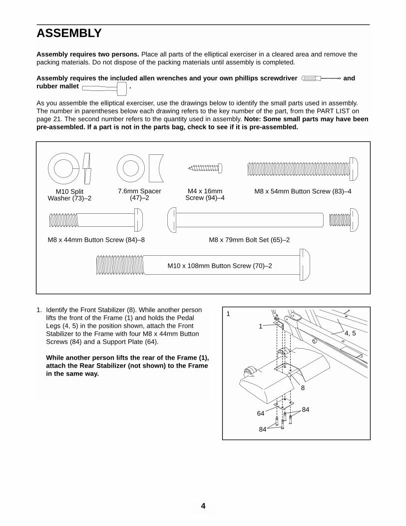
Assembly requires two persons. Place all parts of the elliptical exerciser in a cleared area and remove thepacking materials. Do not dispose of the packing materials until assembly is completed.
Assembly requires the included allen wrenches and your own phillips screwdriver andrubber mallet .
As you assemble the elliptical exerciser, use the drawings below to identify the small parts used in assembly.The number in parentheses below each drawing refers to the key number of the part, from the PART LIST onpage 21. The second number refers to the quantity used in assembly. Note: Some small parts may have beenpre-assembled. If a part is not in the parts bag, check to see if it is pre-assembled.
M8 x 54mm Button Screw (83)–4
M8 x 44mm Button Screw (84)–8
M10 SplitWasher (73)–2
7.6mm Spacer(47)–2
M4 x 16mmScrew (94)–4
M8 x 79mm Bolt Set (65)–2
M10 x 108mm Button Screw (70)–2
1. Identify the Front Stabilizer (8). While another personlifts the front of the Frame (1) and holds the PedalLegs (4, 5) in the position shown, attach the FrontStabilizer to the Frame with four M8 x 44mm ButtonScrews (84) and a Support Plate (64).
While another person lifts the rear of the Frame (1),attach the Rear Stabilizer (not shown) to the Framein the same way.
1
8
4, 51
64
84
84

5
2. Have another person hold the Upright (2) in the posi-tion shown. Make sure that the Upright is turned asshown in drawing 3 below, and that the Upper WireHarness (30) is on the right side of the indicatedmetal plate.
Connect the Upper Wire Harness (30) to the LowerWire Harness (42). Carefully pull the upper end ofthe Upper Wire Harness to remove the slack fromthe Wire Harnesses. Insert the Upright (2) into theFrame (1). Be careful to avoid disconnecting orpinching the Wire Harnesses. Attach the Upright withtwo M10 x 108mm Button Screws (70), two M10 SplitWashers (73), and two 7.6mm Spacers (47). Makesure that the curved sides of the Spacers are fac-ing the Upright. Be careful to avoid damaging theWire Harnesses with the Button Screws. Do nottighten the Button Screws yet.
2
30Plate
7042
1
73
73
47
2
47
3
31
29 28
Grease
2
9629
3. Slide a Weld Spacer (28) onto the axle on the left sideof the Upright (2), with the open side of the WeldSpacer facing the Upright. Apply a small amount ofgrease to the axle.
Slide an Upper Body Arm (29) onto the axle on the leftside of the Upright (2). Using the included Push NutTool (96), tap a Push Nut (31) onto the axle; makesure that the Push Nut is turned as shown in theinset drawing.
Attach the other Upper Body Arm (29) to the rightside of the Upright (2) in the same way.
26
29
2
26
26
4. Look inside one of the Handlebar Covers (26) andlocate the square tabs connecting the two halves.Gently lift the tabs and disconnect the halves.
Hold the two halves of the Handlebar Cover (26)around the tube on the left side of the Upright (2). Alignthe halves and press them together until they lock.
Attach the other Handlebar Cover (26) to the right sideof the Upright (2) in the same way.
4
Axle
Axle31

6
5. Identify the Left Pedal (10), which has a notch nearthe right side. Place the Left Pedal on the Left PedalLeg (4). Next, apply the entire contents of one of theincluded Teflon® lubricant packets to the long side ofan M8 x 79mm Bolt Set (65) and the faces of the twoindicated Upper Body Arm Bushings (12). Have a sec-ond person hold the lower end of the left Upper BodyArm (29) inside of the bracket on the Left Pedal Leg.Align the indicated holes, and attach the Left Pedaland the left Upper Body Arm to the Left Pedal Leg withthe M8 x 79mm Bolt Set.
Attach the other end of the Left Pedal (10) to the LeftPedal Leg (4) with two M8 x 54mm Button Screws (83).
Repeat this step on the right side of the elliptical exer-ciser.
See step 2. Tighten the two M10 x 108mm ButtonScrews (70).
4
10
83
65
565
NotchLube
29
6. The Console (17) requires four “D” batteries (notincluded); alkaline batteries are recommended. Slidethe battery cover off the Console. Insert four batteriesinto the battery compartment. Make sure that the bat-teries are oriented as shown by the diagram insidethe battery compartment. Slide the battery coverback onto the Console. Note: When the batteries areinstalled correctly, the fan will turn on for a moment.
8. Make sure that all parts of the elliptical exerciser are properly tightened. Cover the floor beneath theelliptical exerciser to protect the floor from damage. Note: Some extra hardware may be left over.
The elliptical exerciser is now fully assembled. If you have purchased the optional chest pulse sensor(see page 18), see page 7.
6
17
Batteries
BatteryCover
5
12
Face
Lube
7. Remove the ground wire screw from the Upright (2).Attach the ground wire to the Upright with the groundwire screw as shown.
Have another person hold the Console (17) near theUpright (2). Connect the ground wire to the groundwire on the Console. Connect the Upper Wire Harness(30) to the wire harness on the Console. Connect thetwo Pulse Wires (20) to the pulse wires on theConsole.
Carefully insert all excess wiring down into the Upright(2). Attach the Console to the Upright with four M4 x16mm Screws (94). (Note: The Screws may be foundin the console box.) Be careful to avoid pinching thewires.
17
2
94
94
30
Do not pinchthe wires
during this step.
7
20Ground Wire Screw
GroundWire

7
INSTALLING THE RECEIVER FOR THE OPTIONAL CHEST PULSE SENSOR
If you have purchased the optional chest pulse sensor (see page 18), follow the steps below to install thereceiver included with the optional chest pulse sensor.
1. Look under the Console (17) and locate the accesscover. Remove the access cover.
2. Hold the receiver in the position shown, with the smallcylinder oriented as shown. Using the two screwsincluded with the chest pulse sensor, attach the receiv-er to the two plastic posts (not shown) inside theaccess opening in the back of the Console (17).
3. Connect the wire on the receiver to the indicated wireon the Console (17). Make sure that the connectorson the wires snap together. Discard the other wiresincluded with the chest pulse sensor.
4. Reattach the access cover to the Console (17).
EXERCISING ON THE ELLIPTICAL EXERCISER
To mount the elliptical exerciser, hold the handgrippulse sensor and step onto the pedal that is in thelowest position. Next, step onto the other pedal. Pushthe pedals until they begin to move with a continuousmotion.
To dismount the elliptical exerciser, wait until the ped-als come to a complete stop. The elliptical exercis-er does not have a free wheel; the pedals willcontinue to move until the flywheel stops. Whenthe pedals are stationary, step off the highest pedalfirst. Then, step off the lowest pedal.
Screws
17
Cylinder
Receiver
Access Cover
HOW TO USE THE ELLIPTICAL EXERCISER
Pedals
HandgripPulse Sensor

8
FEATURES OF THE CONSOLE
The advanced console offers a selection of featuresdesigned to make your workouts more enjoyable andeffective. When the manual mode of the console isselected, the resistance of the elliptical exerciser canbe changed with the touch of a button. As you exer-cise, the console will provide continuous exercisefeedback. You can even measure your heart rate usingthe handgrip pulse sensor. Note: For information aboutan optional chest pulse sensor, see page 18.
The console also offers six resistance and pace pro-grams. Each program automatically changes the resis-tance of the elliptical exerciser and prompts you toincrease or decrease your pace as it guides youthrough an effective workout.
In addition, the console features two heart rate pro-grams that automatically change the resistance of theelliptical exerciser and prompt you to vary your pace tokeep your heart rate near a target heart rate as youexercise.
The console also features iFIT.com interactive technol-ogy. Having iFIT.com technology is like having a per-sonal trainer in your home. Using the included audiocable, you can connect the elliptical exerciser to yourhome stereo, portable stereo, computer, or VCR andplay special iFIT.com CD and video programs (iFIT.comCDs and videocassettes are available separately).iFIT.com CD and video programs automatically controlthe resistance of the elliptical exerciser and promptyou to vary your pace as a personal trainer coachesyou through every step of your workout. High-energymusic provides added motivation. To purchaseiFIT.com CDs and videocassettes, call toll-free1-800-735-0768.
With the elliptical exerciser connected to your comput-er, you can also go to our Web site at www.iFIT.comand access programs directly from the internet.Explore www.iFIT.com for more information.
CONSOLE DIAGRAM
Note: If there is a sheet of clear plastic on the face of the console, remove it before using the console.
Matrix Training Zone BarLeft Display

9
HOW TO USE THE MANUAL MODE
Press any button on the console or beginpedaling to turn on the console.
Note: The console requires four 1.5V “D” batteries(see assembly step 6 on page 6).
Press any button on the console or begin pedal-ing to turn on the console. After a few seconds,the console displays will light, a tone sound, andthe console will be ready for use.
Select the manual mode.
When the power isturned on, the manualmode will be select-ed. If you haveselected a program orthe iFIT.com mode,reselect the manualmode by pressing the Program Select buttonrepeatedly until a track appears in the matrix.
Begin pedaling and change the resistance ofthe elliptical exerciser as desired.
As you pedal, changethe resistance of theelliptical exerciser bypressing the Resis-tance buttons. Thereare ten resistancelevels. Note: After theResistance buttons are pressed, it will take amoment for the elliptical exerciser to reach theselected resistance level.
Monitor your progress with the matrix, theTraining Zone bar, and the two displays.
The matrix —Whenthe manual mode isselected, the matrixwill show a track rep-resenting 1/4 mile. Asyou pedal, the indica-
tors around the track will light in succession untilthe entire track is lit. The track will then darkenand the indicators will again begin to light in suc-cession.
The TrainingZone bar —TheTraining Zone barwill show your paceand the approxi-mate intensity levelof your exercise.For example, if three or four indicators in the barare lit, the bar shows that your pace is ideal for fatburning. During programs, the Training Zone barwill also prompt you to increase or decrease yourpace.
The left display —The left display willshow the elapsedtime, your pedalingspeed (in revolutionsper minute), and thetotal number of revolu-tions you have ped-aled. The display will change from one number tothe next every few seconds, as shown by themode indicators in the display. Note: When a pro-gram is selected, the display will show the timeremaining in the program instead of the elapsedtime.
The right display —The right display willshow the approximatenumbers of fat calo-ries and calories youhave burned (see FATBURNING on page20) and the resistance level of the elliptical exer-ciser. The display will change from one number tothe next every few seconds, as shown by themode indicators. The display will also show yourheart rate when you use the handgrip pulse sen-sor or the optional chest pulse sensor. Note: Eachtime the resistance of the elliptical exerciserchanges, the display will show the resistancelevel.
4
3
2
1
Mode Indicator

10
Measure your heart rate if desired.
Note: If you wear the optional chest pulsesensor and hold the handgrip pulse sensor atthe same time, the console may not displayyour heart rate accurately.
If there arethin sheets ofplastic on themetal con-tacts on thehandgrippulse sensor,peel off theplastic. Tomeasure yourheart rate,hold the con-tacts; your palms must be resting on the uppercontacts, and your fingers must be touching thelower contacts. Avoid moving your hands.
When your pulse is detected, the heart-shapedindicator in the right display will flash each timeyour heart beats, one or two dashes (– –) willappear, and then your heart rate will be shown.For the most accurate heart rate reading, hold thecontacts for at least 15 seconds.
Note: If you continue to hold the pulse sensor,the right display will show your heart rate for up
to 30 seconds. The display will then show yourheart rate along with the other modes.
If your heart rate is not shown, make sure thatyour hands are positioned as described. Be care-ful not to move your hands excessively or tosqueeze the metal contacts too tightly. For opti-mal performance, clean the metal contacts usinga soft cloth; never use alcohol, abrasives, orchemicals.
Turn on the fan if desired.
To turn on the fan at low speed, press the Fanbutton. Pivot the fan to the desired angle. To turnon the fan at high speed, press the Fan button asecond time. To turn off the fan, press the Fanbutton a third time. Note: If the pedals are notmoved for about thirty seconds, the fan will auto-matically turn off.
When you are finished exercising, the consolewill automatically turn off.
If the pedals are not moved for several seconds, atone will sound, the console will pause, and theleft display will begin to flash. If the pedals are notmoved for about five minutes, the console willturn off and the displays will be reset.
7
6
5
Contacts

11
HOW TO USE RESISTANCE AND PACEPROGRAMS
Press any button on the console or beginpedaling to turn on the console.
See step 1 on page 9.
Select one of the six resistance and paceprograms.
When the power isturned on, the man-ual mode will beselected. To select aresistance and paceprogram, press theProgram Select but-ton repeatedly until a “P 1,” “P 2,” “P 3,” “P 4,”“P 5,” or “P 6” appears in the right display.
Each program is divided into several time seg-ments of different lengths. One resistance settingand one pace setting are programmed for eachsegment. (Note: The same resistance settingand/or pace setting may be programmed for two ormore consecutive segments.) The resistance set-ting for the first seg-ment is shown in theleft column of thematrix. The resis-tance settings forthe next five seg-ments are shown inthe columns to theright. Note: One barin a column represents a resistance setting oflevel 1, two bars represent level 2 or 3, threebars represent level 4 or 5, four bars representlevel 6 or 7, five bars represent level 8 or 9, andsix bars represent level 10.
Press the Program Start button or beginpedaling to start the program.
When the program is started, the left column ofthe matrix will begin to flash, and the ellipticalexerciser will automatically adjust to the resis-tance setting for the first segment.
As you exercise, the Training Zone bar will helpyou to keep your pedaling pace near the pace
setting for the cur-rent segment. Thelit indicators in thebar will show youractual pace. If anindicator to theright of the lit indi-cators is flashing(see drawing a),increase yourpace. If an indica-tor to the left ofany lit indicator isflashing (see draw-ing b), decrease your pace. When no indicator isflashing, your pace matches the pace setting forthe current segment. Important: The pace set-tings are intended only to provide motivation.Your actual pace may be slower than the cur-rent pace setting. Make sure to exercise at apace that is comfortable for you.
When the first segment of the program ends, aseries of tones will sound and all resistance set-tings will move one column to the left. The resis-tance setting for the second segment will then beshown in the left column of the matrix and theresistance of the elliptical exerciser will automati-cally change to the resistance setting for the sec-ond segment.
Note: During the program, you can override theresistance setting, if desired, by pressing theResistance buttons. However, when the nextsegment begins, the resistance will change if adifferent resistance setting is programmed for thenext segment.
If you stop pedaling for several seconds, a tonewill sound and the program will pause. To restartthe program, simply resume pedaling. The pro-gram will continue until the resistance setting forthe last segment is shown in the left column ofthe matrix and the last segment ends.
Monitor your progress with the two displays.
See step 4 on page 9.
Measure your heart rate if desired.
See step 5 on page 10.
5
43
2
1
Current Segment
a
b

12
Turn on the fan if desired.
See step 6 on page 10.
When the program is finished, the consolewill automatically turn off.
See step 7 on page 10.
HOW TO USE HEART RATE PROGRAMS
Each heart rate program helps you to keep your heartrate near a certain percentage of your maximum heartrate during your workout. (Your maximum heart rate isestimated by subtracting your age from 220. Forexample, if you are 30 years old, your maximum heartrate is 190.) Heart rate program 1 is designed to keepyour heart rate between 50% and 80% of your maxi-mum heart rate while you exercise; heart rate pro-gram 2 is designed to keep your heart rate between50% and 85% of your maximum heart rate.
Follow the steps below to use a heart rate program.
Press any button on the console or beginpedaling to turn on the console.
See step 1 on page 9.
Select one of the heart rate programs.
When the power isturned on, the manu-al mode will beselected. To select aheart rate program,press the ProgramSelect button repeat-edly until an “H 1” or “H 2” appears in the rightdisplay.
During heart rate pro-grams, the matrix willshow a movinggraphic that repre-sents your heart rate.Each time a heart-beat is detected, anadditional peak will appear.
Enter your age.
When a heart rateprogram is selected,the word “AGE” andthe current age set-ting will flash in theleft display. You mustenter your age to usea heart rate program. If you have already enteredyour age, press the Enter button and go to step4. If you have not entered your age, press the +or – button repeatedly to enter your age, andthen press the Enter button. Once you haveentered your age, it will be saved in memory.
Hold the handgrip pulse sensor.
To use a heart rate program, you must use thehandgrip pulse sensor (see step 5 on page 10)or the optional chest pulse sensor. If you use thehandgrip pulse sensor, it is not necessary to holdthe handgrips continuously during the program.However, you should hold the handgrips fre-quently for the program to operate properly. Eachtime you hold the handgrips, keep your handson the metal contacts for at least 30 seconds.Note: When you are not holding the handgrips,the letters “PLS” will appear in the right displayinstead of your heart rate.
Press the Program Start button or beginpedaling to start the program.
When the program is started, the elliptical exer-ciser will automatically adjust to the resistancesetting for the first segment.
Each program is divided into 20 one-minute seg-ments. One resistance setting and one targetheart rate setting are programmed for each seg-ment. Note: The same resistance setting and/ortarget heart rate setting may be programmed fortwo or more consecutive segments.
During the last three seconds of each segment, aseries of tones will sound. The resistance of theelliptical exerciser will then automatically change ifa different resistance setting is programmed forthe next segment.
As you exercise, the Training Zone bar will helpyou to keep your heart rate near the target heart
5
4
3
2
1
7
6

13
rate setting for thecurrent segment.The lit indicatorsin the bar willshow your actualpace. When youhold the handgrippulse sensor orwear the optionalchest pulse sen-sor, the consolewill periodicallycompare yourheart rate to thetarget heart rate setting for the current segment;if necessary, an indicator in the bar will then flashto prompt you to increase or decrease your paceto bring your heart rate closer to the target heartrate setting. If an indicator to the right of the litindicators is flashing (see drawing a), increaseyour pace. If an indicator to the left of any lit indi-cator is flashing (see drawing b), decrease yourpace. When no indicator is flashing, your heartrate is near the target heart rate setting.Important: The target heart rate settings areintended only to provide motivation. Youractual heart rate may be slower than the tar-get heart rate settings. Make sure to exerciseat a pace that is comfortable for you.
Note: During the program, you can override theresistance setting, if desired, by pressing theResistance buttons. However, when the nextsegment begins, the resistance will change if adifferent resistance setting is programmed for thenext segment.
The program will continue until the last segmentends.
If you stop pedaling for several seconds, a tonewill sound and the program will end. Heart rateprograms cannot be stopped temporarily andthen restarted.
Monitor your progress with the two displays.
See step 4 on page 9.
Turn on the fan if desired.
See step 6 on page 10.
When the program is finished, the consolewill automatically turn off.
See step 7 on page 10.
8
7
6
a
b

14
HOW TO CONNECT YOUR CD PLAYER, VCR,OR COMPUTER
To use iFIT.com CDs , the elliptical exerciser must beconnected to your portable CD player, portable stereo,home stereo, or computer with CD player. See pages14 and 15 for connecting instructions. To use iFIT.comvideocassettes , the elliptical exerciser must be con-nected to your VCR. See page 16 for connectinginstructions. To use iFIT.com programs directly fromour Web site , the elliptical exerciser must be connect-ed to your home computer. See page 15 for connect-ing instructions.
HOW TO CONNECT YOUR PORTABLE CD PLAYER
Note: If your CD player has separate LINE OUT andPHONES jacks, see instruction A below. If your CDplayer has only one jack, see instruction B.
A. Plug one end of the audio cable into the jackbeneath the console. Plug the other end of thecable into the LINE OUT jack on your CD player.Plug your headphones into the PHONES jack.
B. Plug one end of the audio cable into the jackbeneath the console. Plug the other end of thecable into a 1/8” Y-adapter (available at electronicsstores). Plug the Y-adapter into the PHONES jackon your CD player. Plug your headphones into theother side of the Y-adapter.
HOW TO CONNECT YOUR PORTABLE STEREO
Note: If your stereo has an RCA-type AUDIO OUTjack, see instruction A below. If your stereo has a1/8” LINE OUT jack, see instruction B. If yourstereo has only a PHONES jack, see instruction C.
A. Plug one end of the audio cable into the jackbeneath the console. Plug the other end of the cableinto the adapter. Plug the adapter into an AUDIOOUT jack on your stereo.
B. Plug one end of the audio cable into the jackbeneath the console. Plug the other end of thecable into the LINE OUT jack on your stereo. Donot use the adapter.
C. Plug one end of the audio cable into the jackbeneath the console. Plug the other end of thecable into a 1/8” Y-adapter (available at electronicsstores). Plug the Y-adapter into the PHONES jackon your stereo. Plug your headphones into theother side of the Y-adapter.
LINE OUT
PHONES LINE OUT
PHONES
AudioCable
Head-phones
A
PHONES
PHONES
AudioCable
1/8” Y-adapter
Headphones
B
AUDIO OUT
RIGHT
LEFT
PHONES
AudioCable
C
1/8” Y-adapter
Headphones
Audio Cable
Adapter
A, B

15
HOW TO CONNECT YOUR HOME STEREO
Note: If your stereo has an unused LINE OUT jack,see instruction A below. If the LINE OUT jack isbeing used, see instruction B.
A. Plug one end of the audio cable into the jackbeneath the console. Plug the other end of thecable into the adapter. Plug the adapter into theLINE OUT jack on your stereo.
B. Plug one end of the audio cable into the jackbeneath the console. Plug the other end of thecable into the adapter. Plug the adapter into anRCA Y-adapter (available at electronics stores).Next, remove the wire that is currently plugged intothe LINE OUT jack on your stereo and plug thewire into the unused side of the Y-adapter. Plug theY-adapter into the LINE OUT jack on your stereo.
HOW TO CONNECT YOUR COMPUTER
Note: If your computer has a 1/8” LINE OUT jack,see instruction A. If your computer has only aPHONES jack, see instruction B.
A. Plug one end of the audio cable into the jackbeneath the console. Plug the other end of thecable into the LINE OUT jack on your computer.
B. Plug one end of the audio cable into the jackbeneath the console. Plug the other end of thecable into a 1/8” Y-adapter (available at electronicsstores). Plug the Y-adapter into the PHONES jackon your computer. Plug your headphones or speak-ers into the other side of the Y-adapter.
CD
VCR
AmpLINE OUT
LINE OUT
AudioCable
Adapter
A
CD
VCR
AmpLINE OUT
AudioCable
RCAY-adapter
Wire removed fromLINE OUT jack
B
Adapter
LINE OUT
AudioCable
A
PHONES
AudioCable
B
1/8” Y-adapter
Headphones/Speakers

16
HOW TO CONNECT YOUR VCR
Note: If your VCR has an unused AUDIO OUT jack,see instruction A below. If the AUDIO OUT jack isbeing used, see instruction B. If you have a TVwith a built-in VCR, see instruction B. If your VCRis connected to your home stereo, see HOW TOCONNECT YOUR HOME STEREO on page 15.
A. Plug one end of the audio cable into the jackbeneath the console. Plug the other end of thecable into the adapter. Plug the adapter into theAUDIO OUT jack on your VCR.
B. Plug one end of the audio cable into the jackbeneath the console. Plug the other end of thecable into the adapter. Plug the adapter into anRCA Y-adapter (available at electronics stores).Next, remove the wire that is currently plugged intothe AUDIO OUT jack on your VCR and plug thewire into the unused side of the Y-adapter. Plug theY-adapter into the AUDIO OUT jack on your VCR.
AUDIO OUT
RIGHT
LEFT
VIDEO AUDIO
ANT. IN
RF OUTIN
OUT
CH3 4
Audio Cable
Adapter
A
VIDEO AUDIO
ANT. IN
RF OUTIN
OUT
CH3 4
Audio Cable Adapter
B
Wire removed fromAUDIO OUT jack
RCA Y-adapter

17
To use iFIT.com CDs or videocassettes, the ellipticalexerciser must be connected to your portable CD play-er, portable stereo, home stereo, computer with CDplayer, or VCR. See HOW TO CONNECT YOUR CDPLAYER, VCR, OR COMPUTER on page 14. To pur-chase iFIT.com CDs and videocassettes, call toll-free 1-800-735-0768.
Follow the steps below to use an iFIT.com CD orvideo program.
Press any button on the console or beginpedaling to turn on the console.
See step 1 on page 9.
Select the iFIT.com mode.
When the console isturned on, the manu-al mode will beselected. To selectthe iFIT.com mode,press the iFIT.combutton. The indicatorabove the button will light.
Insert the iFIT.com CD or videocassette.
If you are using an iFIT.com CD, insert the CDinto your CD player. If you are using an iFIT.comvideocassette, insert the videocassette into yourVCR.
Press the play button on your CD player orVCR.
A moment after the play button is pressed, yourpersonal trainer will begin guiding you through
your workout. Simply follow your personal trainer’sinstructions.
The program will function in almost the same wayas a resistance and pace program (see step 3 onpage 11). However, an electronic “chirping” soundwill alert you when the resistance setting and/orthe pace setting is about to change.
Note: If the resistance of the elliptical exerciserand/or the pace setting does not change whena “chirp” is heard:
• Make sure that the indicator above theiFIT.com button is lit.
• Adjust the volume of your CD player or VCR.If the volume is too high or too low, the con-sole may not detect the program signals.
• Make sure that the audio cable is properlyconnected and that it is fully plugged in.
Monitor your progress with the two displays.
See step 4 on page 9.
Measure your heart rate if desired.
See step 5 on page 10.
Turn on the fan if desired.
See step 6 on page 10.
When the program is finished, the consolewill automatically turn off.
See step 7 on page 10.
8
7
6
5
4
3
2
1
HOW TO USE IFIT.COM CD AND VIDEOPROGRAMS

18
HOW TO USE PROGRAMS DIRECTLY FROM OUR WEB SITE
Our Web site at www.iFIT.com allows you to playiFIT.com audio and video programs directly from theinternet. To use programs from our Web site, the ellip-tical exerciser must be connected to your home com-puter. See HOW TO CONNECT YOUR COMPUTERon page 15. In addition, you must have an internetconnection and an internet service provider. A list ofspecific system requirements is found on our Website.
Follow the steps below to use a program from our Web site.
Press any button on the console or beginpedaling to turn on the console.
See step 1 on page 9.
Select the iFIT.com mode.
When the console isturned on, the manu-al mode will beselected. To selectthe iFIT.com mode,press the iFIT.combutton. The indicatorabove the button will light.
Go to your computer and start an internetconnection.
Start your Web browser, if necessary, and goto our Web site at www.iFIT.com.
Follow the desired links on our Web site toselect a program.
Read and follow the on-line instructions for usinga program.
Follow the on-line instructions to start theprogram.
When you start the program, an on-screen count-down will begin.
Return to the elliptical exerciser and beginpedaling.
When the on-screen countdown ends, the pro-gram will begin. The program will function inalmost the same way as a resistance and paceprogram (see step 3 on page 14). However, anelectronic “chirping” sound will alert you when theresistance setting and/or the pace setting is aboutto change.
Monitor your progress with the two displays.
See step 4 on page 9.
Measure your heart rate if desired.
See step 5 on page 10.
Turn on the fan if desired.
See step 6 on page 10.
When you are finished exercising, the consolewill automatically turn off.
See step 7 on page 10.
THE OPTIONAL CHEST PULSE SENSOR
The optional chest pulse sensor provides hands-freeoperation and continuously monitors your heart rateduring your workouts. To purchase the optionalchest pulse sensor, call toll-free 1-800-734-2377.
11
10
9
8
7
6
5
4
3
2
1

19
Inspect and properly tighten all parts of the ellipticalexerciser regularly. Replace any worn parts immedi-ately.
PULSE SENSOR TROUBLESHOOTING
If the handgrip pulse sensor does not function proper-ly, see step 5 on page 10.
CONSOLE TROUBLESHOOTING
If turning on the fan resets the console displays, or ifthe displays becomes dim, the batteries should bereplaced. Most console problems are the result of lowbatteries. See assembly step 6 on page 6 for replace-ment instructions.
HOW TO LEVEL THE ELLIPTICAL EXERCISER
If the ellipticalexerciser rocksduring use,turn one orboth of the lev-eling feetunder the rearstabilizer untilthe rockingmotion is elimi-nated.
HOW TO MOVE THE ELLIPTICAL EXERCISER
Stand in front of the elliptical exerciser, hold the han-dlebars firmly, and place one foot against one of thewheels. Pull the handlebars until the elliptical exercis-er can be moved on the wheels, and carefully movethe elliptical exerciser to the desired location. Then,place one foot against a wheel, and lower the ellipticalexerciser. Due to the size and weight of the ellipti-cal exerciser, use extreme caution while movingand lowering it.
MAINTENANCE AND TROUBLESHOOTING
LevelingFoot
Handlebars
Wheel

20
CONDITIONING GUIDELINES
The following guidelines will help you to plan yourexercise program. Remember that proper nutritionand adequate rest are essential for successful results.
EXERCISE INTENSITY
Whether your goal is to burn fat or to strengthen yourcardiovascular system, the key to achieving thedesired results is to exercise with the proper intensity.The proper intensity level can be found by using yourheart rate as a guide. The chart below shows recom-mended heart rates for fat burning, maximum fatburning, and cardiovascular (aerobic) exercise.
To find the proper heart rate for you, first find your agenear the bottom of the chart (ages are rounded off tothe nearest ten years). Next, find the three numbersabove your age. The three numbers are your “trainingzone.” The lower two numbers are recommendedheart rates for fat burning; the highest number is therecommended heart rate for aerobic exercise.
Fat Burning
To burn fat effectively, you must exercise at a relative-ly low intensity level for a sustained period of time.
During the first few minutes of exercise, your bodyuses easily accessible carbohydrate calories for ener-gy. Only after the first few minutes of exercise doesyour body begin to use stored fat calories for energy.If your goal is to burn fat, adjust the intensity of yourexercise until your heart rate is near the lowest num-ber in your training zone as you exercise.
For maximum fat burning, adjust the intensity of yourexercise until your heart rate is near the middle num-ber in your training zone as you exercise.
Aerobic Exercise
If your goal is to strengthen your cardiovascular sys-tem, your exercise must be “aerobic.” Aerobic exer-cise is activity that requires large amounts of oxygenfor prolonged periods of time. This increases thedemand on the heart to pump blood to the muscles,and on the lungs to oxygenate the blood. For aerobicexercise, adjust the intensity of your exercise untilyour heart rate is near the highest number in yourtraining zone as you exercise.
WORKOUT GUIDELINES
Each workout should include the following three parts:
A warm-up , consisting of 5 to 10 minutes of stretchingand light exercise. A proper warm-up increases yourbody temperature, heart rate, and circulation in prepa-ration for exercise.
Training zone exercise , consisting of 20 to 30 min-utes of exercising with your heart rate in your trainingzone. (During the first few weeks of your exercise program, do not keep your heart rate in your trainingzone for longer than 20 minutes.)
A cool-down , with 5 to 10 minutes of stretching. Thiswill increase the flexibility of your muscles and willhelp to prevent post-exercise problems.
EXERCISE FREQUENCY
To maintain or improve your condition, complete threeworkouts each week, with at least one day of restbetween workouts. After a few months of regular exer-cise, you may complete up to five workouts each weekif desired. The key to success is to make exercise aregular and enjoyable part of your everyday life.
WARNING:Before beginning this or any exercise pro-gram, consult your physician. This is espe-cially important for persons over the age of 35or persons with pre-existing health problems.
The pulse sensor is not a medical device.Various factors may affect the accuracy ofheart rate readings. The pulse sensor isintended only as an exercise aid in determin-ing heart rate trends in general.

21
1 1 Frame2 1 Upright3 1 Upright Endcap4 1 Left Pedal Leg5 1 Right Pedal Leg6 1 Rear Stabilizer7 1 Rear Stabilizer Cover8 1 Front Stabilizer9 1 Front Stabilizer Cover
10 1 Left Pedal11 1 Right Pedal12 4 Upper Body Arm Bushing13 2 M4 x 19mm Round Head Screw14 4 Upper Body Arm Bushing15 1 Left Side Shield16 1 Right Side Shield17 1 Console18 1 Right Flywheel Cover19 1 Left Flywheel Cover20 2 Pulse Sensor w/Wire21 1 Right Upright Cover22 1 Left Upright Cover23 2 Upper Body Arm Endcap24 2 Upper Body Arm Foam Grip25 2 M4 x 25mm Screw26 2 Handlebar Cover27 1 Frame Cover28 2 Weld Spacer29 2 Upper Body Arm30 1 Upper Wire Harness31 2 Push Nut32 1 “C” Magnet33 1 Magnet Bracket34 1 Left Crank Arm35 2 29.5mm Pulley Spacer36 1 Flywheel37 1 Magnet38 1 Pulley39 1 Belt40 2 Wheel41 2 M8 x 19mm Patch Screw42 1 Lower Wire Harness43 1 Crank44 2 Crank Bearing45 1 Idler46 4 Foot47 2 7.6mm Spacer48 3 M4 x 25mm Tek Screw49 2 Lower Foam Grip50 2 Upper Foam Grip
51 4 Pedal Leg Bushing52 1 Resistance Motor53 1 Reed Switch Bracket54 1 Clamp55 1 Reed Switch/Wire56 1 Return Spring57 1 Guide Rod58 1 Resistance Cable59 1 Flywheel Axle60 2 Flywheel Bearing61 2 Eyebolt62 2 Adjustment Bracket63 2 M8 x 47mm Button Screw64 2 Support Plate65 2 M8 x 79mm Bolt Set66 2 M8 Washer67 2 M10 x 50mm Bolt Set68 1 Flywheel Spacer69 2 M4 x 16mm Round Head Screw70 2 M10 x 108mm Button Screw71 1 M8 Tek Washer72 1 M11 x 40mm Bolt Set73 2 M10 Split Washer74 1 M8 x 25mm Button Screw75 1 M10 x 19mm Button Bolt76 1 Right Crank Arm77 4 M5 Nut78 4 M5 x 16mm Bolt79 4 M5 Washer80 2 M6 x 18mm Bolt81 1 M6 x 25mm Bolt82 2 5/16” x 25mm Flange Screw83 4 M8 x 54mm Button Screw84 8 M8 x 44mm Button Screw85 2 31.5mm Pulley Spacer86 4 M5 Nylon Locknut87 8 M4 x 38mm Screw88 3 M8 Nylon Locknut89 1 M10 Nylon Locknut90 3 M6 Nut91 2 M6 Nylon Locknut92 2 Snap Ring93 2 M8 x 54mm Button Screw94 21 M4 x 16mm Screw95 4 M4 x 19mm Screw96 1 Push Nut Tool# 2 Teflon® Lubricant Packet# 1 Allen Wrench# 1 User’s Manual
Key No. Qty. Description Key No. Qty. Description
PART LIST—Model No. NEL07940 R1203A
Note: # indicates a non-illustrated part. Specifications are subject to change without notice. See the back coverof this manual for information about ordering replacement parts.

22
17
20
69
94
94
2
26
26
26
26
19
18 1594
9494
9448
94
94
16
30
50
49
48
69
24
29
14
14
14
14
29
23
23
48
2828
20
94
12
1212
3
31
31
96
EX
PLO
DE
D D
RA
WIN
G—
Mod
elN
o. N
EL0
7940
R12
03A

23
2594
94
94
94
94
94
2221
9
7 6
4684
84
64
87
8746
54
5594
94
58
77
8
40
4667
67 84
84
87
87
46
67
91
53
78
86
78
5657
7790
81
8032
88
4492
7682
51
51
6641
83
5
65
65
11
2795
13
95
7073
73
65
65
10
83
4
8871
60
9061
6237
36
6059
6888
6162
90
4166
51
51
823485
35
38
63
8945
9275
446343
74
72
72
1
33
52
64
79
79
93
9335
47
47
42
94
39

Part No. 203360 R1203A Printed in China © 2003 ICON Health & Fitness, Inc.
HOW TO ORDER REPLACEMENT PARTSTo order replacement parts, simply call our Customer Service Department toll-free at 1-888-825-2588, Mondaythrough Friday, 6 a.m. until 6 p.m. Mountain Time (excluding holidays). To help us assist you, please be prepared to give the following information when calling:
• The MODEL NUMBER of the product (NEL07940)
• The NAME of the product (NordicTrack® CX 925 elliptical exerciser)
• The SERIAL NUMBER of the product (see the front cover of this manual)
• The KEY NUMBER and DESCRIPTION of the part(s) (see pages 21 to 23)
LIMITED WARRANTY
WHAT IS COVERED—The entire NordicTrack® elliptical exerciser (“Product”) is warranted to be free of all defects in material andworkmanship.
WHO IS COVERED—The original purchaser or any person receiving the Product as a gift from the original purchaser.
HOW LONG IS IT COVERED—ICON Health & Fitness, Inc. (“ICON”), warrants the product for one year after the date of purchase.Labor is covered for one year.
WHAT WE DO TO CORRECT COVERED DEFECTS—We will ship to you, without charge, any replacement part or component, pro-viding the repairs are authorized by ICON first and are performed by an ICON trained and authorized service provider, or, at ouroption, we will replace the Product.
WHAT IS NOT COVERED—Any failures or damage caused by unauthorized service, misuse, accident, negligence, improper assem-bly or installation, alterations, modifications without our written authorization or by failure on your part to use, operate, and maintainas set out in your User’s Manual (“Manual”).
WHAT YOU MUST DO—Always retain proof of purchase, such as your bill of sale; store, operate, and maintain the Product as spec-ified in the Manual; notify our Customer Service Department of any defect within 10 days after discovery of the defect; as instruct-ed, return any defected part for replacement or, if necessary, the entire product, for repair.
USER’S MANUAL—It is VERY IMPORTANT THAT YOU READ THE MANUAL before operating the Product. Remember to do theperiodic maintenance requirements specified in the Manual to assure proper operation and your continued satisfaction.
HOW TO GET PARTS AND SERVICE—Simply call our Customer Service Department at 1-888-825-2588 and tell them your nameand address and the serial number of your Product. They will tell you how to get a part replaced, or if necessary, arrange for servicewhere your Product is located or advise you how to ship the Product for service. Before shipping, always obtain a ReturnAuthorization Number (RA No.) from our Customer Service Department; securely pack your Product (save the original shipping car-ton if possible); put the RA No. on the outside of the carton and insure the product. Include a letter explaining the product or prob-lem and a copy of your proof of purchase if you believe the service is covered by warranty.
ICON is not responsible or liable for indirect, special or consequential damages arising out of or in connection with the use or per-formance of the product or damages with respect to any economic loss, loss of property, loss of revenues or profits, loss of enjoy-ment or use, costs of removal, installation or other consequential damages of whatsoever nature. Some states do not allow the exclu-sion or limitation of incidental or consequential damages. Accordingly, the above limitation may not apply to you.
The warranty extended hereunder is in lieu of any and all other warranties and any implied warranties of merchantability or fitnessfor a particular purpose is limited in its scope and duration to the terms set forth herein. Some states do not allow limitations on howlong an implied warranty lasts. Accordingly, the above limitation may not apply to you.
No one is authorized to change, modify or extend the terms of this limited warranty. This warranty gives you specific legal rights andyou may have other rights which vary from state to state.
ICON HEALTH & FITNESS, INC., 1500 S. 1000 W., LOGAN, UT 84321-9813