Embed Size (px)
Citation preview

User’sManual
Yokogawa Electric Corporation
DX1000/DX1000N/DX2000PROFIBUS-DP (/CP1)Communication Interface
IM 04L41B01-19E3rd Edition

�IM 04L4�B0�-�9E
Thank you for purchasing Daqstation DX�000, DX�000N, or DX2000 (Hereafter, called "DX").This manual explains the PROFIBUS-DP (/CP� option) communication function of the DX. Read this manual together with other User's Manuals (IM04L4�B0�-0�E, IM04L42B0�-0�E, and IM04L4�B0�-�7E).
Notes● Thecontentofthismanualmaychangewithoutpriornoticeinviewof improvingthe
performance and function.● Weensurethecontentofthismanual.If,however,thereareanymistakesorquestionable
points,contactourbranchoffice,branchstore,orbusinessoffice.● Reprintingor reproductionof all or parts of the content of thismanual is prohibited
without permission.● WedevelopedandcreatedtheTCP/IPsoftwareandTCP/IPsoftwaredocumentsofthis
productbasedonBSDNetworkingSoftwareRelease1licensedfromtheUniversityofCalifornia.
Trademarks● vigilantplant,DAQSTATION,Daqstation, andDXAdvancedareour registered
trademarks. ● Microsoft andWindowsare the registered trademarksor trademarksofMicrosoft
Corporation in the United States and other countries.● AdobeandAcrobatare the registered trademarksor trademarksofAdobeSystems
Incorporated.● KerberosisatrademarkoftheMassachusettsInstituteofTechnology(MIT).● Other product and company names described in thismanual are registered
trademarksortrademarksoftheirrespectivecompanies.● Thismanual doesnot displaymarks ®and™ for the registered trademarksor
trademarks of each company.
RevisionsNovember2008: 1stEditionMarch2010: 2ndEditionDecember2010: 3rdEdition
3rdEditionDecember2010(YK)AllRightReserved,Copyright©2008,YokogawaElectricCorporation
2 IM 04L4�B0�-�9E
Symbols Used in This Manual
● Units• k:Denotes1000.Examples:5kg,100kHz• K:Denotes1024.Example:640Kbytes
● CautionarynotesInthisUser'sManual,cautionarynotesaredistinguishedbythefollowingsymbols:
Refer to corresponding location on the instrument. This symbol appears on dangerous locations on the instrument which require special instructions for proper handling or use. The same symbol appears in the corresponding place in the manual to identify those instructions.
WARNING Calls attention to actions or conditions that could cause serious
injury or death to the user, and precautions that can be taken to prevent such occurrences.
CAUTION Calls attentions to actions or conditions that could cause light
injury to the user or damage to the instrument or user’s data, and precautions that can be taken to prevent such occurrences.
Note Calls attention to information that is important for proper operation of the instrumen
● Boldcharacters Denotes key or character string that appear on the DX screen. Thesymbol indicates the key operation and menu selection procedure on the DX.

3IM 04L4�B0�-�9E
Assumption of ExplanationTheexplanation in thismanualassumes that theDX isconnectedviacommunicationswith ProgrammableLogicController(PLC).ForinformationonhowtooperatePLCs,seetheuser'smanualofrespectiveproducts.
ThismanualisintendedforthosewhohaveusedanPROFIBUS-DP.
In this manual, the screens of the DX�000 are used. The content displayed on the DX2000 screens are not different from those displayed on the DX�000 screen.
Revision HistoryEdition DX Description� Releasenumber3
(Version3.0x)Newlypublished.
Stylenumber32 Releasenumber4
(Version 4.0x)Additionsandimprovementstoexplanations.
Stylenumber33 Same as edition 2. Fixed explanations.

4 IM 04L4�B0�-�9E
Contents
SymbolsUsedinThisManual ...................................................................................................................2AssumptionofExplanation ........................................................................................................................3RevisionHistory .........................................................................................................................................3
Introduction of Features ......................................................................................................................5PROFIBUS-DP ..........................................................................................................................................5WhattheDXCanDo .................................................................................................................................6Settings of the DX ......................................................................................................................................6AccesstotheDX .......................................................................................................................................6
Connection to the PROFIBUS-DP Network ........................................................................................7CableConnection ......................................................................................................................................7Settings of the DX ......................................................................................................................................8Others ........................................................................................................................................................8
Preparation for PLC ............................................................................................................................9GSD File ....................................................................................................................................................9SpecificationofData ................................................................................................................................�0Communication Connection .....................................................................................................................�0
I/O Buffer and Data Mapping ............................................................................................................��MappingMethodoftheI/Obuffer ............................................................................................................ ��Data Count and Data Type ...................................................................................................................... ��Data Mapping ..........................................................................................................................................�2
Specifications ....................................................................................................................................23BasicSpecifications .................................................................................................................................23
Index .................................................................................................................................................24

5IM 04L4�B0�-�9E
Introduction of Features
PROFIBUS-DPPROFIBUS is anopen field bus standard (IEC61158) used in variousapplications forfactory automation and process automation.PROFIBUS-DP(DecentralizedPeriphery)isusedforcommunicationbetweenPLCsandremoteI/O,enablinghigh-speeddatatransmission.
Configuration ComponentsPROFIBUS-DPnetworkconsistsoffollowingcomponents:• Class � master Acontrollertoexchangeinformationwiththeslaveinacyclicmanner.ThisisaPLCor
PC.• Class 2 master Engineeringandconfigurationdevices.This is eitheraPConwhich configuration
softwarehasbeeninstalledorsoftwareitself.• Slave I/Odevicesaccessedbythemaster.ThisincludesI/Odevices,sensors,oractuaters.
TheDXisaslavedevice.• Terminator Theterminatorofthebus.• Cable Adedicatedtwo-wirecableisused.• Others Repeater, coupler, and other components are also used if needed.
Node127nodescanbeconnectedtothenetwork.
NoteFordetailsofPROFIBUSspecificationsandinformation,seethedocumentspublishedfromthePROFIBUSOrganizationinrespectiveregions.
PROFIBUS-DP
Slave Slave Slave
PROFIBU-DP Master (Class 1) PLC etc.
PROFIBU-DP Master (Class 2) PC
Terminator Terminator
Cable

6 IM 04L4�B0�-�9E
What the DX Can DoTheDXprovidesthefollowingfunctions:• ParticipateinanPROFIBUS-DPnetworkasaPROFIBUS-DPslave.• Communicate with a PLC from Siemens.• The master can access internal data of the DX.
Data AccessMeasurement channel data ReadComputation channel*� data ReadCommunication input data*�*2 Write*� This is an option (/M� and /PM�).*2 Communication input data, if coded in a calculation expression in the computation channel,
canbedisplayedontheDX.
The following shows examples of usage.• DataondevicesonanetworkcanberecordedbyaPLCtotheDX.• DatameasuredbytheDXcanbeacquiredbyaPLC.
Settings of the DXTheDXisreadytouseafterthenodeaddresssettingshavebeenmade.
Access to the DXTheDXisapassivedeviceonanPROFIBUS-DP.TheDXcannotinitiatearequest.PLC,aclass1masterdevice,initiatesarequestandaccessestheDX.
Introduction of Features

7IM 04L4�B0�-�9E
Connection to the PROFIBUS-DP Network
Cable ConnectionConnectthePROFIBUS-DPcabletoaPROFIBUS-DPconnectorprovidedonthebackof the DX.
5 4 3 2 1
9 8 7 6 (Rear panel)
ConnectorD-sub9-pin(female)connector.Eachpincorrespondstothefollowingsignals.Pin Signal name Explanation3 RxD/TxD - P Positivedatareceive/transmit.4 CNTR - P RTS(forusebyrepeater).5 DGND Ground.6 VP+5V +5V.8 RxD/TxD - N Negativedatareceive/transmit.Pins �, 2, 7, and 9 are not used.
CableAdedicatedtwo-wirecableisused(twowiresforthesignal).ThisisnotsuppliedwiththeDX.Tobepreparedseparately.
Transmission Rate/Transmission DistanceThetransmissionratevariesdependingonthetransmissiondistancewithinthefollowingrange.9.6Kbps/1200mto12Mbps/100m
TerminatorTheDXhasnobuilt-interminatorcircuit.Ifaterminatorisneededintermsofwiring,usea connector with a terminator.
8 IM 04L4�B0�-�9E
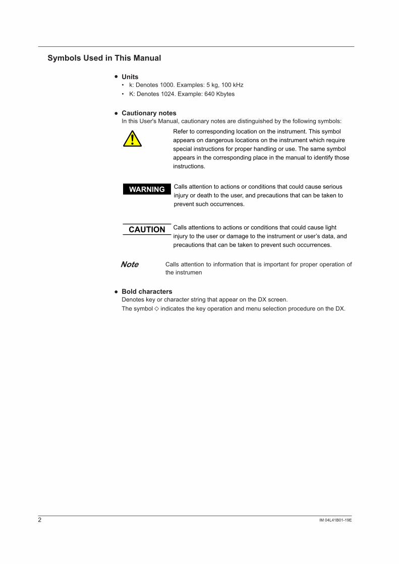
Settings of the DXNode Address Settings
Press MENU (to switch to setting mode), hold down FUNCfor3s(toswitchtobasicsetting mode), and select the Menutab> Communication (PROFIBUS).
• Node Address Setanodeaddressintherangeof0to125.
NoteThenodeaddressofPROFIBUS-DPcanbecheckedontheNetworkInformationScreenoftheDX.YoucanopentheNetworkInformationScreenbypressingFUNC>Network info softkey.
OthersStatus Output (option, /F1 and /F2)If setting Communication error of the Status Output (/F� or /F2 option) to On, a relay outputisprovidedwhenaPROFIBUS-DPcommunicationerroroccurswithintheDX.Ifacommunicationerroroccurs,contactyournearestYOKOGAWAdealerforrepairs.See Section 2.9 of the DX1000/DX1000N User's Manual (IM04L41B01-01E) or DX2000 User's Manual (IM04142B01-01E).
In Basic Setting Mode:WhentheDXisinthebasicsettingmode,communicationsareavailablebutinput/outputdataisinvalid.
Connection to the PROFIBUS-DP Network

9IM 04L4�B0�-�9E
Preparation for PLC
GSD FileInstallationTohave theDXparticipate inanetwork,youmust first install theDXdevicedatabasefile (GSD file) in the configurationtool.APLCcommunicateswiththeDXbasedontheinformation in the GSD file.For information on using the configuration tool, see the configuration tool user's manual.
PROFIBU-DP
GSD file
PROFIBUS configuration tool
DX
PLC
How to Obtain the GSD FileObtaintheGSDfilefromtheYokogawaWebsite:URL:www.yokogawa.com/ns/dxadv/download/
Contents of the GSD FileContentsotherthanthoselistedinthefollowingtableareomitted.Item DescriptionModel Name DataAcquisitionPROFIBUSI/FSlaveFamily 0

�0 IM 04L4�B0�-�9E
Specification of DataIf you install the GSD file, the DX is added to the configuration tool as a "General" type "Slave".Select[Model]toexpandthemodulelistandselectyourDXmodelfromthelist.Item ExplanationModel ThemodelnamedescribedintheGSDfile.Selectthedeviceto
beconfiguredfromthemodelnameofthe"General"typeandthe"Slave"inthedevicestreeorlistbox.
DataAcquisitionPROFIBUSI/F
Module The DX models are referred to as modules. Selecting the model"DataAcquisitionPROFIBUSI/F"allowsyoutoselectamodule.
DX�002 DX�002, DX�002N, without Option/M� and /PM�DX�002/M� DX�002, DX�002N, with Option/M� or /PM�DX�004 DX�004, DX�004N, without Option/M� and /PM�DX�004/M� DX�004, DX�004N, with Option/M� or /PM�DX1006 DX1006,DX1006N,withoutOption/M1and/PM1DX1006/M1 DX1006,DX1006N,withOption/M1or/PM1DX�0�2 DX�0�2, DX�0�2N, without Option/M� and /PM�DX�0�2/M� DX�0�2, DX�0�2N, with Option/M� or /PM�DX2004 DX2004, without Option/M� and /PM�DX2004/M� DX2004, with Option/M� or /PM�DX2008 DX2008,withoutOption/M1and/PM1DX2008/M1 DX2008,withOption/M1or/PM1DX20�0 DX20�0, without Option/M� and /PM�DX20�0/M� DX20�0, with Option/M� or /PM�DX2020 DX2020, without Option/M� and /PM�DX2020/M� DX2020, with Option/M� or /PM�DX2030 DX2030,withoutOption/M1and/PM1DX2030/M1 DX2030,withOption/M1or/PM1DX2040 DX2040, without Option/M� and /PM�DX2040/M� DX2040, with Option/M� or /PM�DX2048 DX2048,withoutOption/M1and/PM1DX2048/M1 DX2048,withOption/M1or/PM1
Communication ConnectionYoucanestablisha communication connectionbyusing the configuraton tool and runit with a PLC. For information on using the configuration tool and a PLC, see the user's manuals of these products.
Preparation for PLC

��IM 04L4�B0�-�9E
I/O Buffer and Data Mapping
AmasterdevicesuchasaPLCaccesses internaldataof theDXvia the"Inputbuffer"and"Outputbuffer"oftheDX."Input"representsaninputtothemaster,while"Output"represents an output from the master.
Mapping Method of the I/O bufferThe "Inputbuffer"and"Outputbuffer"oftheDXforPROFIBUS-DPcommunicationhas128byteseach.Dataislaidoutasdescribedinthefollowingtable.Datalayoutcannotbechanged.Buffer Application DescriptionInput Reading
measurement channel data and computation channel data
Locates all the measurement channel data from the top of thebuffer.Locatesasmuchcomputationchanneldataaspossibleintheremainingpartofthebuffer.
Buffer Application DescriptionOutput Writing
communication input data
Locatesasmuchcommunicationinputdataaspossible.
Data Count and Data TypeTheDXdatacountisasfollows:Model Measurement channel Computation channel Communication input
dataCount Number Count Number Count Number
DX�002 2 00�, 002 �2 �0� to ��2 24 C0� to C24DX�004 4 00� to 004DX1006 6 001to006 24 �0� to �24DX�0�2 �2 00� to 0�2DX2004 4 00� to 004 �2 �0� to ��2 60 C01toC32
(C33toC60)*�DX2008 8 001to008DX20�0 �0 00� to 0�0 60 �0� to �27
(128to160)*�
DX2020 20 00� to 020 �0� to �22(123to160)*�
DX2030 30 001to030 �0� to ��7(118to160)*�
DX2040 40 00� to 040 �0� to ��2(113to160)*�
DX2048 48 001to048 101to108(109to160)*�
*1DatainparenthesescannotbelocatedinabufferbecauseitexceedsthecapacityoftheI/Obuffer.
NoteThe communication input data forC01 toC24 (on theDX1000) or forC01 toC32 (on theDX2000)isreservedforPROFIBUS-DP.Youcannotwritetothesedatanumbersthroughothermeans(suchasModbus,EtherNet/IP,orcommunication commands).
�2 IM 04L4�B0�-�9E
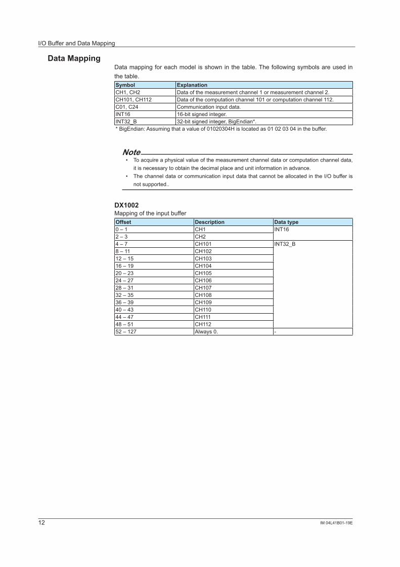
Data MappingDatamappingforeachmodel isshowninthetable.Thefollowingsymbolsareusedinthetable.Symbol ExplanationCH�, CH2 Data of the measurement channel � or measurement channel 2.CH�0�, CH��2 Data of the computation channel �0� or computation channel ��2.C0�, C24 Communication input data.INT16 16-bitsignedinteger.INT32_B 32-bitsignedinteger,BigEndian*.*BigEndian:Assumingthatavalueof01020304Hislocatedas01020304inthebuffer.
Note• Toacquireaphysicalvalueofthemeasurementchanneldataorcomputationchanneldata,
itisnecessarytoobtainthedecimal place and unitinformationinadvance.• ThechanneldataorcommunicationinputdatathatcannotbeallocatedintheI/Obufferis
not supported..
DX1002MappingoftheinputbufferOffset Description Data type0 – � CH� INT162–3 CH24 – 7 CH�0� INT32_B8–11 CH�0212–15 CH10316–19 CH�0420–23 CH10524 – 27 CH10628–31 CH�0732–35 CH10836–39 CH�0940–43 CH��044 – 47 CH���48–51 CH��252–127 Always0. -
I/O Buffer and Data Mapping

13IM 04L4�B0�-�9E
MappingoftheoutputbufferOffset Description Data type0–3 C0� INT32_B4 – 7 C028–11 C0312–15 C0416–19 C0520–23 C0624 – 27 C0728–31 C0832–35 C0936–39 C�040–43 C��44 – 47 C�248–51 C1352–55 C�456–59 C1560–63 C1664–67 C�768–71 C1872–75 C�976–79 C2080–83 C2�84–87 C2288–91 C2392–95 C2496–127 Ignore anything that is written. -
DX1004MappingoftheinputbufferOffset Description Data type0 – � CH� INT162–3 CH24–5 CH36–7 CH48–11 CH�0� INT32_B12–15 CH�0216–19 CH10320–23 CH�0424 – 27 CH10528–31 CH10632–35 CH�0736–39 CH10840–43 CH�0944 – 47 CH��048–51 CH���52–55 CH��256–127 Always0. -
MappingoftheoutputbufferSameasforthemappingoftheDX1002outputbuffer.
I/O Buffer and Data Mapping

�4 IM 04L4�B0�-�9E
DX1006MappingoftheinputbufferOffset Description Data type0 – � CH� INT162–3 CH24–5 CH36–7 CH48–9 CH5�0 – �� CH612–15 CH�0� INT32_B16–19 CH�0220–23 CH10324 – 27 CH�0428–31 CH10532–35 CH10636–39 CH�0740–43 CH10844 – 47 CH�0948–51 CH��052–55 CH���56–59 CH��260–63 CH11364–67 CH��468–71 CH11572–75 CH11676–79 CH��780–83 CH11884–87 CH��988–91 CH�2092–95 CH�2�96–99 CH�22100–103 CH123�04 – �07 CH�24108–127 Always0. -
MappingoftheoutputbufferSameasforthemappingoftheDX1002outputbuffer.
I/O Buffer and Data Mapping
15IM 04L4�B0�-�9E
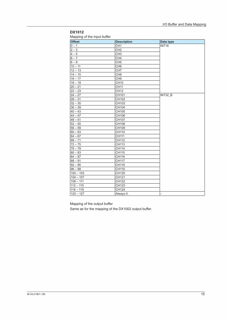
DX1012MappingoftheinputbufferOffset Description Data type0 – � CH� INT162–3 CH24–5 CH36–7 CH48–9 CH5�0 – �� CH612–13 CH714–15 CH816–17 CH918–19 CH�020 – 2� CH��22–23 CH�224 – 27 CH�0� INT32_B28–31 CH�0232–35 CH10336–39 CH�0440–43 CH10544 – 47 CH10648–51 CH�0752–55 CH10856–59 CH�0960–63 CH��064–67 CH���68–71 CH��272–75 CH11376–79 CH��480–83 CH11584–87 CH11688–91 CH��792–95 CH11896–99 CH��9100–103 CH�20�04 – �07 CH�2�108–111 CH�22112–115 CH123116–119 CH�24�20 – �27 Always0. -
MappingoftheoutputbufferSameasforthemappingoftheDX1002outputbuffer.
I/O Buffer and Data Mapping
16 IM 04L4�B0�-�9E
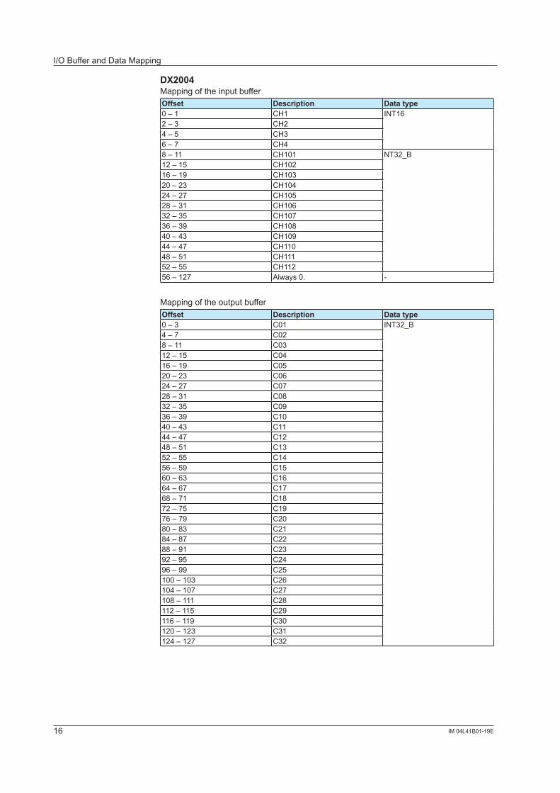
DX2004MappingoftheinputbufferOffset Description Data type0 – � CH� INT162–3 CH24–5 CH36–7 CH48–11 CH�0� NT32_B12–15 CH�0216–19 CH10320–23 CH�0424 – 27 CH10528–31 CH10632–35 CH�0736–39 CH10840–43 CH�0944 – 47 CH��048–51 CH���52–55 CH��256–127 Always0. -
MappingoftheoutputbufferOffset Description Data type0–3 C0� INT32_B4 – 7 C028–11 C0312–15 C0416–19 C0520–23 C0624 – 27 C0728–31 C0832–35 C0936–39 C�040–43 C��44 – 47 C�248–51 C1352–55 C�456–59 C1560–63 C1664–67 C�768–71 C1872–75 C�976–79 C2080–83 C2�84–87 C2288–91 C2392–95 C2496–99 C25100–103 C26�04 – �07 C27108–111 C28112–115 C29116–119 C30120–123 C31�24 – �27 C32
I/O Buffer and Data Mapping

�7IM 04L4�B0�-�9E
DX2008MappingoftheinputbufferOffset Description Data type0 – � CH� INT162–3 CH24–5 CH36–7 CH48–9 CH5�0 – �� CH612–13 CH714–15 CH816–19 CH�0� NT32_B20–23 CH�0224 – 27 CH10328–31 CH�0432–35 CH10536–39 CH10640–43 CH�0744 – 47 CH10848–51 CH�0952–55 CH��056–59 CH���60–63 CH��264–127 Always0. -
MappingoftheoutputbufferSameasforthemappingoftheDX2004outputbuffer.
I/O Buffer and Data Mapping

18 IM 04L4�B0�-�9E
DX2010MappingoftheinputbufferOffset Description Data type0 – � CH� INT162–3 CH24–5 CH36–7 CH48–9 CH5�0 – �� CH612–13 CH714–15 CH816–17 CH918–19 CH�020–23 CH�0� INT32_B24 – 27 CH�0228–31 CH10332–35 CH�0436–39 CH10540–43 CH10644 – 47 CH�0748–51 CH10852–55 CH�0956–59 CH��060–63 CH���64–67 CH��268–71 CH11372–75 CH��476–79 CH11580–83 CH11684–87 CH��788–91 CH11892–95 CH��996–99 CH�20100–103 CH�2��04 – �07 CH�22108–111 CH123112–115 CH�24116–119 CH125120–123 CH126�24 – �27 CH�27
MappingoftheoutputbufferSameasforthemappingoftheDX2004outputbuffer.
I/O Buffer and Data Mapping

�9IM 04L4�B0�-�9E
DX2020Mappingoftheinputbuffer]Offset Description Data type0 – � CH� INT162–3 CH24–5 CH36–7 CH48–9 CH5�0 – �� CH612–13 CH714–15 CH816–17 CH918–19 CH�020 – 2� CH��22–23 CH�224–25 CH1326–27 CH�428–29 CH1530–31 CH1632–33 CH�734–35 CH1836–37 CH�938–39 CH2040–43 CH�0� INT32_B44 – 47 CH�0248–51 CH10352–55 CH�0456–59 CH10560–63 CH10664–67 CH�0768–71 CH10872–75 CH�0976–79 CH��080–83 CH���84–87 CH��288–91 CH11392–95 CH��496–99 CH115100–103 CH116�04 – �07 CH��7108–111 CH118112–115 CH��9116–119 CH�20120–123 CH�2��24 – �27 CH�22
MappingoftheoutputbufferSameasforthemappingoftheDX2004outputbuffer.
I/O Buffer and Data Mapping

20 IM 04L4�B0�-�9E
DX2030MappingoftheinputbufferOffset Description Data type0 – � CH� INT162–3 CH24–5 CH36–7 CH48–9 CH5�0 – �� CH612–13 CH714–15 CH816–17 CH918–19 CH�020 – 2� CH��22–23 CH�224–25 CH1326–27 CH�428–29 CH1530–31 CH1632–33 CH�734–35 CH1836–37 CH�938–39 CH2040 – 4� CH2�42–43 CH2244–45 CH2346–47 CH2448–49 CH2550–51 CH2652–53 CH2754–55 CH2856–57 CH2958–59 CH3060–63 CH�0� INT32_B64–67 CH�0268–71 CH10372–75 CH�0476–79 CH10580–83 CH10684–87 CH�0788–91 CH10892–95 CH�0996–99 CH��0100–103 CH����04 – �07 CH��2108–111 CH113112–115 CH��4116–119 CH115120–123 CH116�24 – �27 CH��7
MappingoftheoutputbufferSameasforthemappingoftheDX2004outputbuffer.
I/O Buffer and Data Mapping

2�IM 04L4�B0�-�9E
DX2040MappingoftheinputbufferOffset Description Data type0 – � CH� INT162–3 CH24–5 CH36–7 CH48–9 CH5�0 – �� CH612–13 CH714–15 CH816–17 CH918–19 CH�020 – 2� CH��22–23 CH�224–25 CH1326–27 CH�428–29 CH1530–31 CH1632–33 CH�734–35 CH1836–37 CH�938–39 CH2040 – 4� CH2�42–43 CH2244–45 CH2346–47 CH2448–49 CH2550–51 CH2652–53 CH2754–55 CH2856–57 CH2958–59 CH3060–61 CH3162–63 CH3264–65 CH3366–67 CH3468–69 CH3570 – 7� CH3672–73 CH3774–75 CH3876–77 CH3978–79 CH4080–83 CH�0� INT32_B84–87 CH�0288–91 CH10392–95 CH�0496–99 CH105100–103 CH106�04 – �07 CH�07108–111 CH108112–115 CH�09116–119 CH��0120–123 CH����24 – �27 CH��2
MappingoftheoutputbufferSameasforthemappingoftheDX2004outputbuffer.
I/O Buffer and Data Mapping

22 IM 04L4�B0�-�9E
DX2048MappingoftheinputbufferOffset Description Data type0 – � CH� INT162–3 CH24–5 CH36–7 CH48–9 CH5�0 – �� CH612–13 CH714–15 CH816–17 CH918–19 CH�020 – 2� CH��22–23 CH�224–25 CH1326–27 CH�428–29 CH1530–31 CH1632–33 CH�734–35 CH1836–37 CH�938–39 CH2040 – 4� CH2�42–43 CH2244–45 CH2346–47 CH2448–49 CH2550–51 CH2652–53 CH2754–55 CH2856–57 CH2958–59 CH3060–61 CH3162–63 CH3264–65 CH3366–67 CH3468–69 CH3570 – 7� CH3672–73 CH3774–75 CH3876–77 CH3978–79 CH4080–81 CH4�82–83 CH4284–85 CH4386–87 CH4488–89 CH4590 – 9� CH4692–93 CH4794–95 CH4896–99 CH�0� INT32_B100–103 CH�02�04 – �07 CH103108–111 CH�04112–115 CH105116–119 CH106120–123 CH�07�24 – �27 CH108
MappingoftheoutputbufferSameasforthemappingoftheDX2004outputbuffer.
I/O Buffer and Data Mapping

23IM 04L4�B0�-�9E
Specifications
Basic SpecificationsItem SpecificationsData mapping See "I/O Buffer and Data Mapping".Node address 0to125Interface PROFIBUS-DP-V0SlaveTransmission media Dedicatedtwo-wirecable(twowireforthesignal)Transmission rate/Transmission distance
9.6Kbps/1200mto12Mbps/100m
Terminator Notbuilt-in(Externalterminationisrequired.)
TheDXdataupdateintervalTheDXdataisupdatedinascaninterval.However,itisnotfasterthan250ms.

Index
Ccable ......................................................................................5, 7cableconnection.........................................................................7class � master ............................................................................5class 2 master ............................................................................5communication input data.........................................................��computation channel ................................................................��configuration components ..........................................................5configuration tool ........................................................................9connector ....................................................................................7
Ddata count .................................................................................��data mapping ............................................................................�2data type ...................................................................................��decimal place............................................................................�2DX settings .................................................................................6
GGSD file ......................................................................................9
Iinputbuffer ................................................................................��installation...................................................................................9
Mmapping method .......................................................................��measurement channel ..............................................................��
Nnode............................................................................................5node address .......................................................................8, 23
Ooutputbuffer .............................................................................��
Pprogrammablelogiccontroller ....................................................3
Rreleasenumber...........................................................................3revisionhistory............................................................................3
Sslave ...........................................................................................5specifications ............................................................................23standard......................................................................................5status output ...............................................................................8stylenumber ...............................................................................3symbols(usedinthemanual).....................................................2
Tterminator ..............................................................................5, 7transmission distance .................................................................7transmission rate ........................................................................7
Uunit ............................................................................................�2
Index
24 IM 04L41B01-19E
![PROFIBUS DP bus interface, PROFIBUS DP [BU 2700]...Sicherheit/PROFIBUS DP [BU 2700]/Bestimmungsgemäße Ver wendung PROFIBUS DP @ 8\mod_1461835577600_388.docx @ 2249429 @ 2 @ 1 2.1](https://img.dokumen.tips/doc/110x75/60b54c574bd00c04b50e633d/profibus-dp-bus-interface-profibus-dp-bu-2700-sicherheitprofibus-dp-bu.jpg)
![BU 2700 PROFIBUS DP Busschnittstelle - NORD€¦ · Sicherheit/PROFIBUS DP [BU 2700]/Bestimmungsgemäße Ver wendung PROFIBUS DP @ 8\mod_1461835577600_6.docx @ 2249428 @ 2 @ 1 2.1](https://img.dokumen.tips/doc/110x75/5eab6d581394d0309b74d9e9/bu-2700-profibus-dp-busschnittstelle-nord-sicherheitprofibus-dp-bu-2700bestimmungsgeme.jpg)