Embed Size (px)
Citation preview
October 2005
Users’ Manual
Pub. No. 234-3298-01
Model 59-T and Model 59EZ Glide™ Evacuation Chair
MODEL 59-T
MODEL 59
2 © Ferno-Washington, Inc. 234-3298-01 October 2005
Models 59 and 59-T Evacuation Chair
Disclaimer
This manual contains general instructions for the use, operation andcare of this chair. The instructions are not all-inclusive. Safe and properuse of this chair is solely at the discretion of the user. Safety informationis included as a service to the user. All other safety measures taken bythe user should be within and under consideration of applicableregulations. It is recommended that training on the proper use of thischair be provided before using this chair in an actual situation.
Retain this manual for future reference. Include it with the chair in theevent of transfer to new users. Additional free copies are availableupon request from Customer Relations.
Proprietary Notice
The information disclosed in this manual is the property of Ferno-Washington, Inc., Wilmington, Ohio, USA. Ferno-Washington, Inc.reserves all patent rights, proprietary design rights, manufacturingrights, reproduction use rights, and sales use rights thereto, and to anyarticle disclosed therein except to the extent those rights are expresslygranted to others or where not applicable to vendor proprietary parts.
Ferno-Washington, Inc.70 Weil Way
Wilmington, OH 45177-9371 U.S.A.
© Copyright Ferno-Washington, Inc. All Rights Reserved.
Telephone (Toll Free) ......................... 1.877.733.0911Telephone ........................................... 1.937.382.1451Fax (Toll Free) .................................... 1.888.388.1349Fax ..................................................... 1.937.382.6569Internet ............................................... www.ferno.com
Additional Instructional Material Available for theEZ Glide Evacuation Chair
EZ Glide Training CD 283-1214

© Ferno-Washington, Inc. 234-3298-01 October 2005 3
Models 59 and 59-T Evacuation Chair
TABLE OF CONTENTSSection page1 - Safety Information .................................................. 5-7
1.1 Warnings .............................................................. 5
1.2 Important .............................................................. 5
1.3 Bloodborne Disease Notice ................................. 5
1.4 Safety and Instruction Labels ........................... 5-7
2 - Operator Skills and Training .................................... 7
2.1 Skills .................................................................... 7
2.2 Training ................................................................ 7
3 - About the Chair ...................................................... 8, 9
3.1 Chair Description ................................................. 8
3.2 General Specifications ......................................... 8
3.3 Components ......................................................... 9
4 - Chair Setup ......................................................... 10, 11
4.1 Restraint Configurations for
Chair with ABS Panels ...................................... 10
4.2 Using One-Piece Restraints ............................... 10
4.3 Ankle Restraint ................................................... 11
4.4 Attaching Restraints to Chair With Soft
Vinyl Seating ....................................................... 11
5 - Using the Features ............................................... 12-15
5.1 Chair Lock Bar .................................................. 12
5.2 Track System - Model 59-T Only ...................... 13
5.3 Extending Lift Bar ............................................. 14
5.4 Telescoping Lift Handles ................................... 14
5.5 Footrest .............................................................. 15
5.6 Wheel Locks ...................................................... 15
6 - Using the Chair ................................................... 16-22
6.1 Before Placing the Chair in Service .................. 16
6.2 General Guidelines for Use ............................... 16
6.3 Transferring the Patient ..................................... 17
6.4 Rolling the Chair ................................................ 17
Section page6.5 Gliding the Chair Down Stairs -
Model 59-T Only ......................................... 18, 19
6.6 Transporting the Patient Down Stairs -
Model 59 Only ................................................... 20
6.7 Transporting the Patient Up Stairs -
Models 59-T and 59 .......................................... 21
6.8 Using Additional Help ....................................... 22
7 - Maintenance ........................................................ 23-30
7.1 Maintenance Schedule ....................................... 23
7.2 Disinfecting/Cleaning Restraints ....................... 23
7.3 Disinfecting/Cleaning the Chair ........................ 23
7.4 Cleaning Track and Belts ................................... 23
7.5 Inspecting the Chair ........................................... 24
7.6 Lubricating the Chair ......................................... 25
7.7 Do Not Lubricate Track System
on Model 59-T ................................................... 25
7.8 Adjusting Track-Belt Tension ...................... 26, 27
7.9 Reconditioning the Track Belts ......................... 28
7.10 Removing and Attaching ABS Panels .............. 29
7.11 Removing and Attaching Soft Vinyl Seating ... 30
8 - Accessories and Related Products .......................... 31
8.1 Accessories ........................................................ 31
8.2 Restraints ........................................................... 31
9 - Parts and Service ............................................... 32, 33
9.1 Parts and Service - U.S.A. and Canada ............. 32
9.2 Parts and Service - Worldwide .......................... 32
9.3 Parts List ............................................................ 32
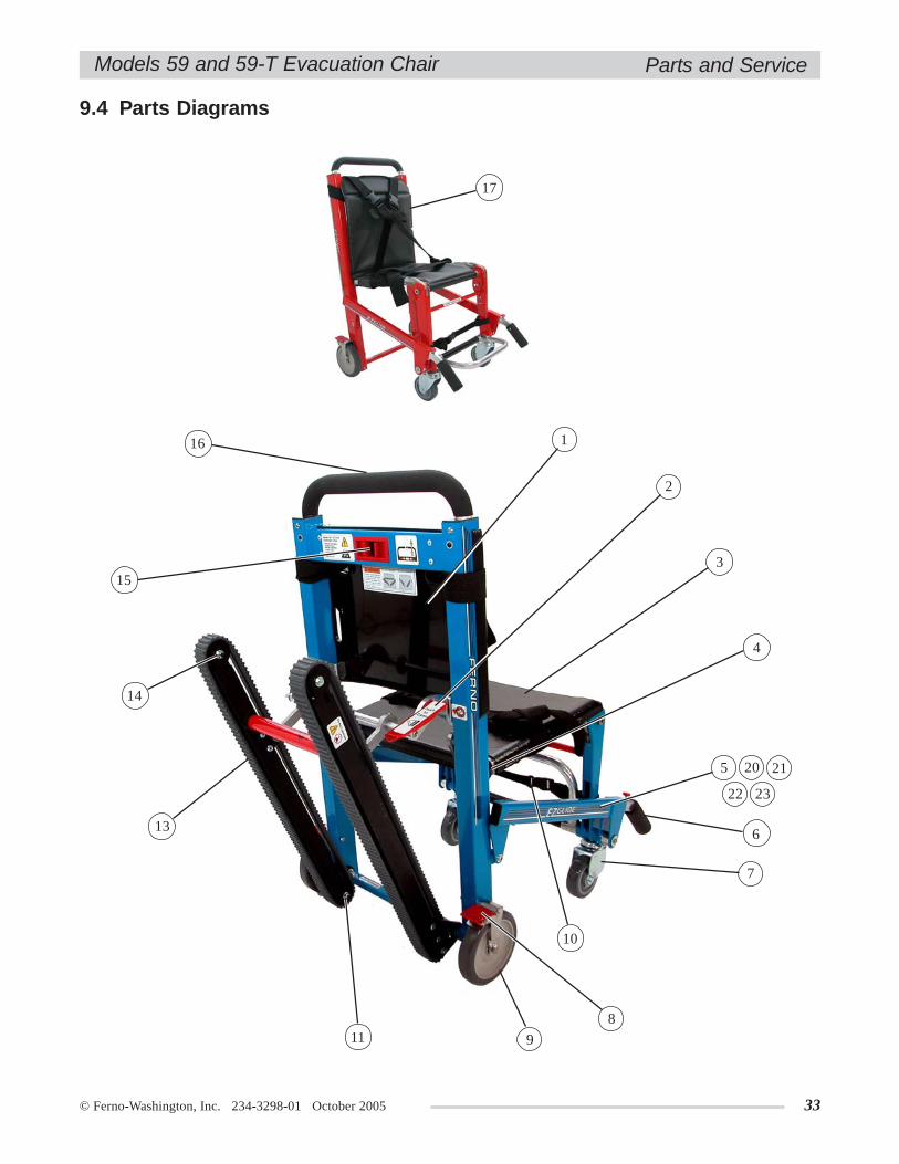
9.4 Parts Diagrams .................................................. 33
10 - Limited Warranty .................................................. 34
11 - Ferno Customer Relations ..................................... 34
Training Record ............................................................. 35
Maintenance Record ..................................................... 36
4 © Ferno-Washington, Inc. 234-3298-01 October 2005
Models 59 and 59-T Evacuation Chair
Safety Labels ................................................................. 6, 7
Components - Model 59-T and Model 59 ......................... 9
Figure 1- Horizontal Restraint Configuration ................. 10
Figure 2 - Criss-Cross Restraint Configuration .............. 10
Figure 3 - Top: Correctly Wrapped One-Piece Restraint
Inset: Restraint Buckled .................................... 10
Figure 4 - Threading Buckle Through Loop .................... 11
Figure 5 - Tightening Strap .............................................. 11
Figure 6 - Ankle Restraint Attached ................................. 11
Figure 7 - Torso Restraints on Chair with Soft
Vinyl Seating ....................................................... 11
Figure 8 - Aligning the Wheels ....................................... 12
Figure 9 - Disengaging the Lock ..................................... 12
Figure 10 - Folding the Chair .......................................... 12
Figure 11 - Engaging the Lock ........................................ 12
Figure 12 - Opening the Track ........................................ 13
Figure 13 - Closing the Track .......................................... 13
Figure 14 - Left: Lift-Bar Positions
Inset: Adjusting Lift Bar Height ........................ 14
Figure 15 - Right: Lift Handle Positions
Inset: Extending/Retracting a Lift Handle ......... 14
Figure 16 - Footrest Folded for Storage .......................... 15
Figure 17 - Footrest Unfolded for Use ............................ 15
Figure 18 - Wheel Lock Engaged ................................... 15
Figure 19 - Wheel Lock Disengaged............................... 15
Figure 20 - Patient Secured in Chair with Restraints ...... 17
Figure 21 - Rolling the Chair .......................................... 17
Figure 22 - Gliding the Chair Down a Curb ................... 17
Figure 23 - Preparing Model 59-T for Descent .............. 18
Figure 24 - Track Belts Engaging Top Step .................... 18
Figure 25 - Establishing the Glide Angle ........................ 19
Figure 26 - Preparing to Roll the Chair .......................... 19
Illustrations
Figure 27 - Pausing on the Stairs .................................... 19
Figure 28 - Carrying the Model 59 Chair
Down Stairs ........................................................ 20
Figure 29 - Pausing on the Stairs - Model 59 Chair ....... 20
Figure 30 - Preparing to Carry Model 59-T (Tracked) ........
Chair Up Stairs .................................................. 21
Figure 31 - Carrying Model 59 (Untracked)
Chair Up Stairs .................................................. 21
Using Additional Help ..................................................... 22
Minimum Intervals for Maintenance ............................... 23
Figure 32 - Top: Lubrication Point Locations
Bottom: Lubrication Point Close-up ................. 25
Figure 33 - Label on Chair Track .................................... 25
Figure 34 - Chair Ready for Tensioning Procedure ........ 26
Figure 35 - Belt Ready for Tensioning ........................... 26
Figure 36 - Tensioning the Belt ....................................... 26
Figure 37 - Checking Tension with Chair Laying on Its ......
Tracks on a Work Bench .................................... 27
Figure 38 - Checking Tension with Chair Standing on Its ...
Wheels ............................................................... 27
Figure 39 - Marking Starting Point for Sanding Belt ...... 28
Figure 40 - Sand in Direction of Arrows ......................... 28
Figure 41 - Releasing a Bottom Corner of Backrest ....... 29
Figure 42 - Lifting the Backrest Panel
Over the Keepers ............................................... 29
Figure 43 - Releasing a Corner of the Seat Panel ........... 29
Figure 44 - Unfasten Snaps ............................................. 30
Figure 45 - Unbuckle Straps ............................................ 30
Figure 46 - Unfasten Seat Snaps ..................................... 30
Figure 47 - Tighten Straps ............................................... 30
Parts Diagrams ................................................................ 33
Serial Number Location .................................................. 34
© Ferno-Washington, Inc. 234-3298-01 October 2005 5
Models 59 and 59-T Evacuation Chair
1 - SAFETY INFORMATION
Safety Information
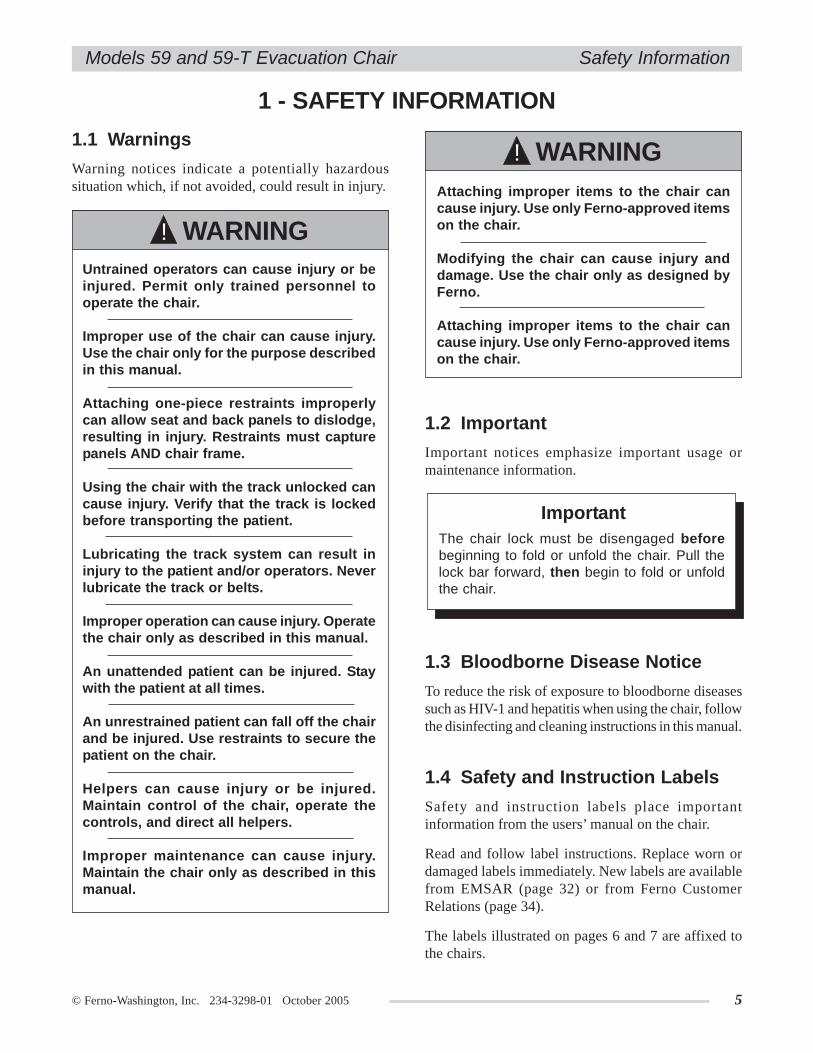
1.1 Warnings
Warning notices indicate a potentially hazardoussituation which, if not avoided, could result in injury.
Untrained operators can cause injury or beinjured. Permit only trained personnel tooperate the chair.
Improper use of the chair can cause injury.Use the chair only for the purpose describedin this manual.
Attaching one-piece restraints improperlycan allow seat and back panels to dislodge,resulting in injury. Restraints must capturepanels AND chair frame.
Using the chair with the track unlocked cancause injury. Verify that the track is lockedbefore transporting the patient.
Lubricating the track system can result ininjury to the patient and/or operators. Neverlubricate the track or belts.
Improper operation can cause injury. Operatethe chair only as described in this manual.
An unattended patient can be injured. Staywith the patient at all times.
An unrestrained patient can fall off the chairand be injured. Use restraints to secure thepatient on the chair.
Helpers can cause injury or be injured.Maintain control of the chair, operate thecontrols, and direct all helpers.
Improper maintenance can cause injury.Maintain the chair only as described in thismanual.
Attaching improper items to the chair cancause injury. Use only Ferno-approved itemson the chair.
Modifying the chair can cause injury anddamage. Use the chair only as designed byFerno.
Attaching improper items to the chair cancause injury. Use only Ferno-approved itemson the chair.
WARNING!
WARNING!
1.2 Important
Important notices emphasize important usage ormaintenance information.
1.3 Bloodborne Disease Notice
To reduce the risk of exposure to bloodborne diseasessuch as HIV-1 and hepatitis when using the chair, followthe disinfecting and cleaning instructions in this manual.
1.4 Safety and Instruction Labels
Safety and instruction labels place importantinformation from the users’ manual on the chair.
Read and follow label instructions. Replace worn ordamaged labels immediately. New labels are availablefrom EMSAR (page 32) or from Ferno CustomerRelations (page 34).
The labels illustrated on pages 6 and 7 are affixed tothe chairs.
ImportantThe chair lock must be disengaged beforebeginning to fold or unfold the chair. Pull thelock bar forward, then begin to fold or unfoldthe chair.
6 © Ferno-Washington, Inc. 234-3298-01 October 2005
Models 59 and 59-T Evacuation ChairSafety Information
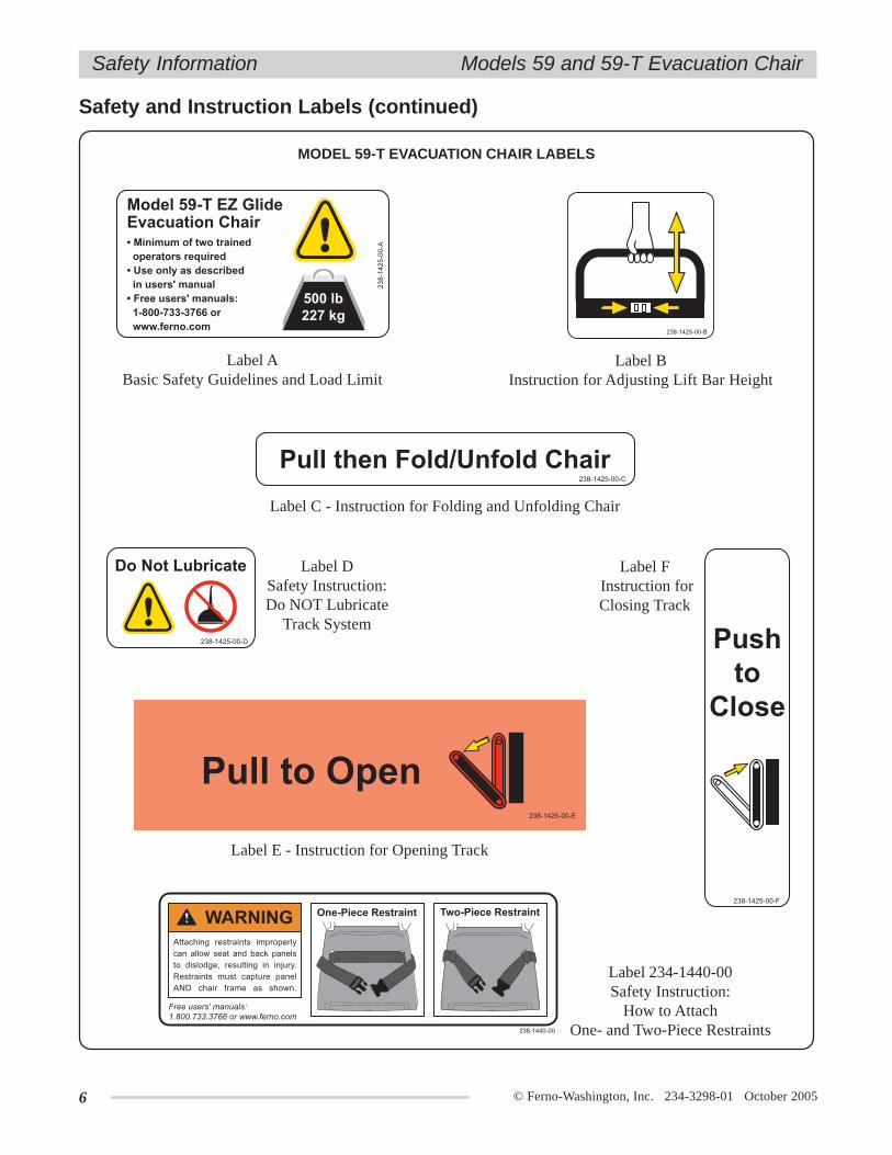
Safety and Instruction Labels (continued)
MODEL 59-T EVACUATION CHAIR LABELS
Label ABasic Safety Guidelines and Load Limit
Label C - Instruction for Folding and Unfolding Chair
Label E - Instruction for Opening Track
Label 234-1440-00Safety Instruction:
How to AttachOne- and Two-Piece Restraints
Label DSafety Instruction:Do NOT Lubricate
Track System
Label F Instruction forClosing Track
Label BInstruction for Adjusting Lift Bar Height

© Ferno-Washington, Inc. 234-3298-01 October 2005 7
Models 59 and 59-T Evacuation Chair
2 - OPERATOR SKILLS AND TRAINING
2.1 Skills
Operators using the chair need:
a working knowledge of emergency patient-handling procedures.
the ability to assist the patient.
a complete understanding of the proceduresdescribed in this manual.
2.2 Training
Trainees need to:
follow a training program designed by theirtraining officer.
read this manual. For additional free users’ manuals,contact Ferno Customer Relations (page 34).
practice with the chair before using it in regularservice.
be tested on their understanding of the chair.
record their training information. A sampletraining record sheet is provided on page 35.
Operator Skills and Training
Safety and Instruction Labels (continued)
MODEL 59 EVACUATION CHAIR LABELS
Label C - Instruction for Folding andUnfolding Chair
Label BInstruction for Adjusting Lift Bar Height
Label JBasic Safety Guidelines and Load Limit
Label 234-1440-00Safety Instruction:
How to AttachOne- and Two-Piece Restraints
Untrained operators can cause injury or beinjured. Permit only trained personnel tooperate the chair.
WARNING!

8 © Ferno-Washington, Inc. 234-3298-01 October 2005
Models 59 and 59-T Evacuation Chair
3 - ABOUT THE CHAIR
3.1 Chair Description
The Model 59-T and Model 59 EZ Glide™ EvacuationChairs (referred to as the "chair" in this manual) areemergency patient-handling devices designed totransport a seated patient up and down stairs and overflat surfaces.
The chair is for professional use by a minimum of twotrained operators. A third person to "spot" may berequired by local protocols, and additional help maybe required when working with heavy patients.
The Model 59-T is designed with belted tracks thatenable operators to "glide" the chair down stairs insteadof carrying it. The Model 59 is untracked and is carrieddown stairs.
Chair features include:
• Belted track system for "gliding" chair down stairs(Model 59-T only)
• Choice of molded ABS seat and back panels orsoft vinyl seating
• 5-position extending lift bar at rear of chair• 5-position telescoping front lift handles• 6" rear locking wheels• 4" front swivel wheels• Folding footrest• Ankle restraint• Multiple patient restraint options
About the Chair
Improper use of the chair can cause injury.Use the chair only for the purpose describedin this manual.
WARNING!
Optional Accessories:
• Rear lift handles, locking or non-locking• IV bag holder• O2 bottle holder• Headrest (head pad with strap)• Kwik Klip™ Restraint System• Secure Mount (with spring release) for storing chair
in ambulance or station• Bracket (with hooks) for storing chair in station
LOAD LIMIT
Inspect the chair if the loadlimit has been exceeded
(see Inspecting theChair, page 24 ).
500 lb227 kg
* without restraints or accessories
Some specifications are rounded to the nearest whole number.Metric conversions are calculated before rounding theImperial measurements. For more information, contact FernoCustomer Relations (page 34).
Ferno reserves the right to change specifications withoutnotice.
3.2 General SpecificationsHeight
Maximum .........................................63.5 in/161 cmMinimum ............................................ 37.5 in/95 cm
WidthOverall .........................................20.313 in/51.6 cmSeat .....................................................16.5 in /42cm
Depth (front to back, Model 59-T)Tracks Closed, Handles Retracted ........ 28 in/73 cmTracks Open, Handles Extended ......... 51 in/130 cm
Depth (front to back, Model 59)Handles Retracted ................................. 27 in/69 cmHandles Extended ............................... 40 in/102 cm
Folded (Model 59-T)......................................... 37.5 in x 20.313 in x 8 in......................................... 95 cm x 51.6 cm x 20 cm
Folded (Model 59)......................................... 37.5 in x 20.313 in x 7 in......................................... 95 cm x 51.6 cm x 18 cm
Weight*Model 59-T ............................................33 lb/15 kgModel 59 ................................................26 lb/12 kg
Load Limit ............................................500 lb/227 kg
© Ferno-Washington, Inc. 234-3298-01 October 2005 9
Models 59 and 59-T Evacuation Chair
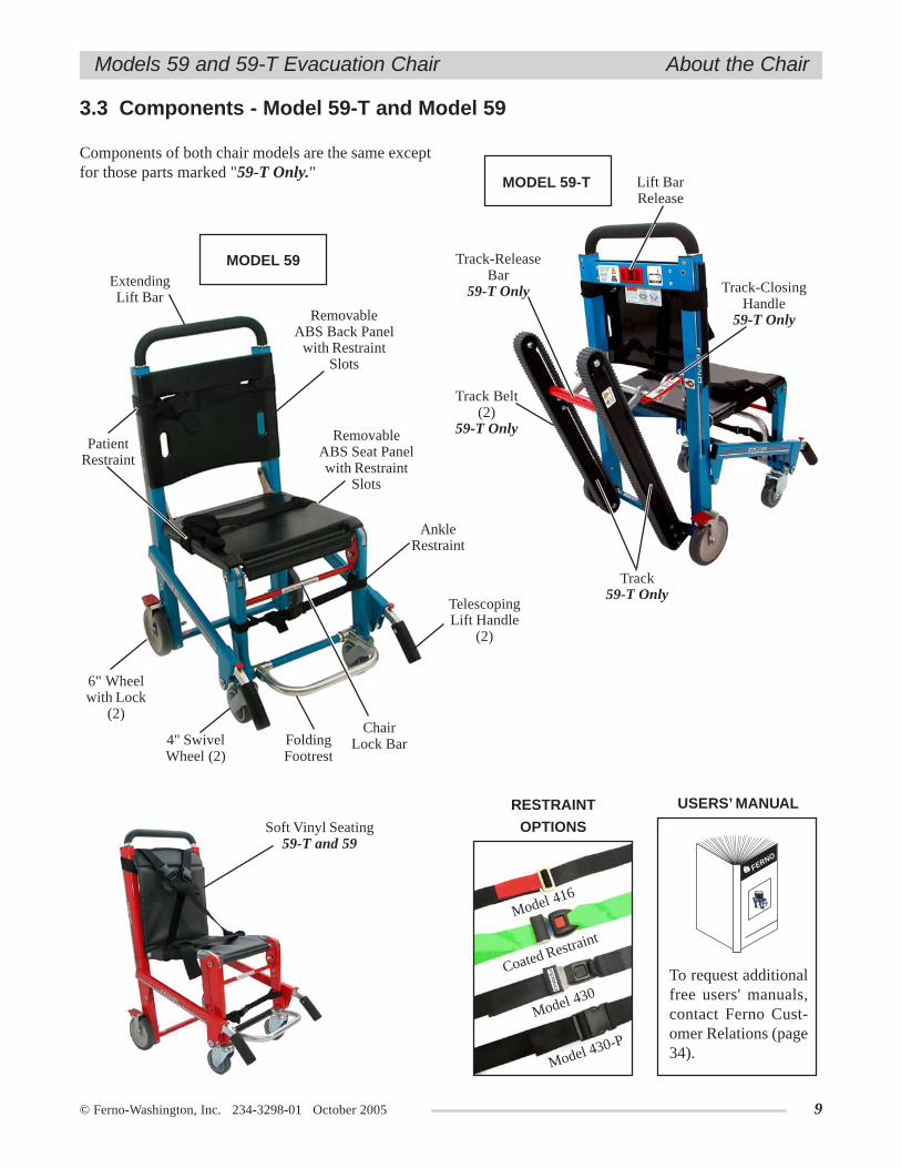
3.3 Components - Model 59-T and Model 59
About the Chair
Components of both chair models are the same exceptfor those parts marked "59-T Only."
Track Belt(2)
59-T Only
Lift BarRelease
Track59-T Only
Track-ClosingHandle
59-T Only
Track-ReleaseBar
59-T Only
MODEL 59-T
RemovableABS Seat Panelwith Restraint
Slots
ExtendingLift Bar
RemovableABS Back Panel
with RestraintSlots
FoldingFootrest
TelescopingLift Handle
(2)
4" SwivelWheel (2)
6" Wheelwith Lock
(2)Chair
Lock Bar
PatientRestraint
MODEL 59
AnkleRestraint
Soft Vinyl Seating59-T and 59
To request additionalfree users' manuals,contact Ferno Cust-omer Relations (page34).
USERS’ MANUAL
FERNO
RESTRAINT
OPTIONS
Model 430-P
Model 430
Coated Restraint
Model 416
10 © Ferno-Washington, Inc. 234-3298-01 October 2005
Models 59 and 59-T Evacuation Chair
4 - CHAIR SETUP
Chair Setup
Figure 1 -HorizontalRestraint
Configuration
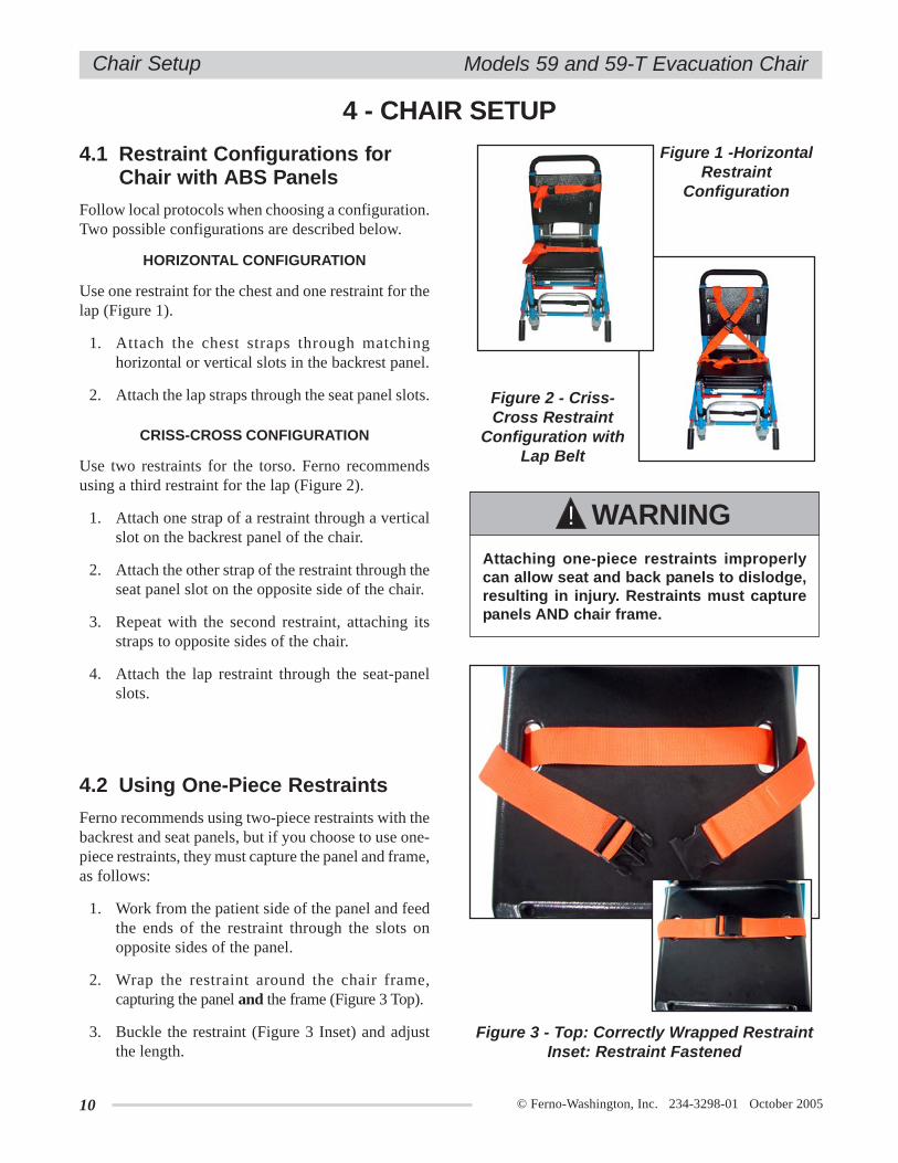
CRISS-CROSS CONFIGURATION
Use two restraints for the torso. Ferno recommendsusing a third restraint for the lap (Figure 2).
1. Attach one strap of a restraint through a verticalslot on the backrest panel of the chair.
2. Attach the other strap of the restraint through theseat panel slot on the opposite side of the chair.
3. Repeat with the second restraint, attaching itsstraps to opposite sides of the chair.
4. Attach the lap restraint through the seat-panelslots.
Figure 2 - Criss-Cross Restraint
Configuration withLap Belt
HORIZONTAL CONFIGURATION
Use one restraint for the chest and one restraint for thelap (Figure 1).
1. Attach the chest straps through matchinghorizontal or vertical slots in the backrest panel.
2. Attach the lap straps through the seat panel slots.
4.1 Restraint Configurations forChair with ABS Panels
Follow local protocols when choosing a configuration.Two possible configurations are described below.
4.2 Using One-Piece Restraints
Ferno recommends using two-piece restraints with thebackrest and seat panels, but if you choose to use one-piece restraints, they must capture the panel and frame,as follows:
1. Work from the patient side of the panel and feedthe ends of the restraint through the slots onopposite sides of the panel.
2. Wrap the restraint around the chair frame,capturing the panel and the frame (Figure 3 Top).
3. Buckle the restraint (Figure 3 Inset) and adjustthe length.
Attaching one-piece restraints improperlycan allow seat and back panels to dislodge,resulting in injury. Restraints must capturepanels AND chair frame.
WARNING!
Figure 3 - Top: Correctly Wrapped RestraintInset: Restraint Fastened
© Ferno-Washington, Inc. 234-3298-01 October 2005 11
Models 59 and 59-T Evacuation Chair
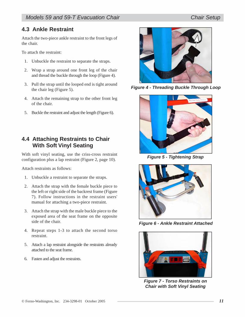
4.3 Ankle Restraint
Attach the two-piece ankle restraint to the front legs ofthe chair.
To attach the restraint:
1. Unbuckle the restraint to separate the straps.
2. Wrap a strap around one front leg of the chairand thread the buckle through the loop (Figure 4).
3. Pull the strap until the looped end is tight aroundthe chair leg (Figure 5).
4. Attach the remaining strap to the other front legof the chair.
5. Buckle the restraint and adjust the length (Figure 6).
Figure 4 - Threading Buckle Through Loop
Figure 6 - Ankle Restraint Attached
Figure 7 - Torso Restraints onChair with Soft Vinyl Seating
Figure 5 - Tightening Strap
Chair Setup
4.4 Attaching Restraints to ChairWith Soft Vinyl Seating
With soft vinyl seating, use the criss-cross restraintconfiguration plus a lap restraint (Figure 2, page 10).
Attach restraints as follows:
1. Unbuckle a restraint to separate the straps.
2. Attach the strap with the female buckle piece tothe left or right side of the backrest frame (Figure7). Follow instructions in the restraint users'manual for attaching a two-piece restraint.
3. Attach the strap with the male buckle piece to theexposed area of the seat frame on the oppositeside of the chair.
4. Repeat steps 1-3 to attach the second torsorestraint.
5. Attach a lap restraint alongside the restraints alreadyattached to the seat frame.
6. Fasten and adjust the restraints.
12 © Ferno-Washington, Inc. 234-3298-01 October 2005
Models 59 and 59-T Evacuation Chair
5 - USING THE FEATURES
Using the Features
UNFOLDING THE CHAIR
1. Stand beside the chair and grasp the backrest withone hand and the lock bar with the other hand.
2. Pull the lock bar forward, then pull the seat awayfrom the backrest until it is fully unfolded andthe lock engages.
3. Verify that the lock has engaged by holding thebackrest in place while pulling up on the chairframe at the front of the seat without pulling thelock bar. The chair will not fold if the lock isengaged.
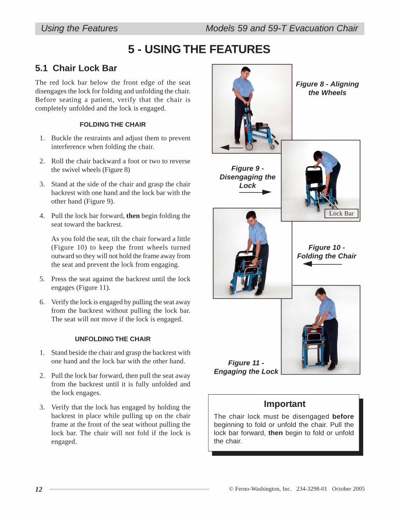
FOLDING THE CHAIR
1. Buckle the restraints and adjust them to preventinterference when folding the chair.
2. Roll the chair backward a foot or two to reversethe swivel wheels (Figure 8)
3. Stand at the side of the chair and grasp the chairbackrest with one hand and the lock bar with theother hand (Figure 9).
4. Pull the lock bar forward, then begin folding theseat toward the backrest.
As you fold the seat, tilt the chair forward a little(Figure 10) to keep the front wheels turnedoutward so they will not hold the frame away fromthe seat and prevent the lock from engaging.
5. Press the seat against the backrest until the lockengages (Figure 11).
6. Verify the lock is engaged by pulling the seat awayfrom the backrest without pulling the lock bar.The seat will not move if the lock is engaged.
5.1 Chair Lock Bar
The red lock bar below the front edge of the seatdisengages the lock for folding and unfolding the chair.Before seating a patient, verify that the chair iscompletely unfolded and the lock is engaged.
Figure 11 -Engaging the Lock
Figure 8 - Aligningthe Wheels
ImportantThe chair lock must be disengaged beforebeginning to fold or unfold the chair. Pull thelock bar forward, then begin to fold or unfoldthe chair.
Figure 9 -Disengaging the
Lock
Figure 10 -Folding the Chair
Lock Bar

© Ferno-Washington, Inc. 234-3298-01 October 2005 13
Models 59 and 59-T Evacuation Chair
5.2 Track System - Model 59-T Only
The EZ Glide track system enables operators to glidethe chair down stairs instead of lifting and carrying it.
OPENING THE TRACK
1. Grasp the track-release bar located near thetop of the track (Figure 12) and firmly pull itback until the track locks into the fully extendedposition.
2. Verify that the lock is engaged by trying to pushthe track closed. If the lock is fully engaged thetrack will not move.
CLOSING THE TRACK
With your hand, push down on the red track-closinghandle (Figure 13) until the track closes completely.
Figure 12 - Opening the Track
Lubricating the track system can result ininjury to patient and/or operators. Neverlubricate the track or belts.
WARNING!
Figure 13 - Closing the Track
• Using the chair on stairs requires a minimum oftwo trained operators. Ferno recommends using athird person as a "spotter" (see Gliding the ChairDown Stairs, page 18).
• Verify that the track system is fully opened andlocked into place before using it.
• Never lubricate track belts. Lubricated track beltscan perform unpredictably, resulting in injury tothe patient and/or operators.
• Moisture, water, snow, ice, or debris on orbetween the track and belts can cause irregulartrack-belt performance that results in suddenchanges in the weight operators must support.Make sure the track and track belts are clean anddry before using the chair on stairs.
• Water, snow, ice, or debris on the stairs can causepoor footing for operators. To avoid possibleinjury, clear the stairs or select an alternate route.
GUIDELINES FOR USING THE TRACK SYSTEM
Using the chair with the track unlocked cancause injury. Verify that the track is lockedbefore transporting the patient.
WARNING!
Using the Features
14 © Ferno-Washington, Inc. 234-3298-01 October 2005
Models 59 and 59-T Evacuation Chair
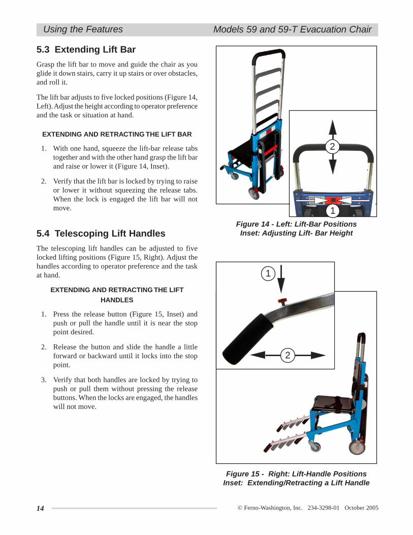
5.3 Extending Lift Bar
Grasp the lift bar to move and guide the chair as youglide it down stairs, carry it up stairs or over obstacles,and roll it.
The lift bar adjusts to five locked positions (Figure 14,Left). Adjust the height according to operator preferenceand the task or situation at hand.
EXTENDING AND RETRACTING THE LIFT BAR
1. With one hand, squeeze the lift-bar release tabstogether and with the other hand grasp the lift barand raise or lower it (Figure 14, Inset).
2. Verify that the lift bar is locked by trying to raiseor lower it without squeezing the release tabs.When the lock is engaged the lift bar will notmove.
Figure 15 - Right: Lift-Handle PositionsInset: Extending/Retracting a Lift Handle
5.4 Telescoping Lift Handles
The telescoping lift handles can be adjusted to fivelocked lifting positions (Figure 15, Right). Adjust thehandles according to operator preference and the taskat hand.
EXTENDING AND RETRACTING THE LIFT
HANDLES
1. Press the release button (Figure 15, Inset) andpush or pull the handle until it is near the stoppoint desired.
2. Release the button and slide the handle a littleforward or backward until it locks into the stoppoint.
3. Verify that both handles are locked by trying topush or pull them without pressing the releasebuttons. When the locks are engaged, the handleswill not move.
Figure 14 - Left: Lift-Bar PositionsInset: Adjusting Lift- Bar Height
Using the Features
2
1
2
1

© Ferno-Washington, Inc. 234-3298-01 October 2005 15
Models 59 and 59-T Evacuation Chair
5.5 Footrest
The footrest has two positions: raised, for storage,(Figure 16) and lowered for use (Figure 17).
To lower the footrest, swing it down until it stops.
To raise the footrest, swing it up until it stops.
Figure 16 - FootrestRaised for Storage
5.6 Wheel Locks
The rear wheels of the chair are fitted with wheel locksto help keep the chair from rolling during patienttransfer.
Stay with the chair and maintain control of it at all times.Do not use the wheel locks as a substitute for operatorcontrol.
To engage a wheel lock, press down on the rear end ofthe lock pedal (Figure 18).
To disengage a wheel lock, press down on the forwardend of the lock pedal (Figure 19).
Using the Features
GUIDELINES FOR USING THE FOOTREST
Use the footrest properly to ensure that is does notinterfere with patient's or operators' feet.
• Before transferring the patient onto the chair,make sure the footrest is raised in the storageposition.
• When preparing to transfer the patient off thechair, unfasten the ankle restraint and raise thefootrest into the storage position beforeunfastening the patient's torso and lap restraints.This will prevent the patient from attempting tostand before the footrest has been stored out of theway of his/her feet.
• Keep the footrest raised when it is not in use.
Figure 19 - WheelLock Disengaged
Figure 18 - WheelLock Engaged
ImportantRaise the footrest into the storage positionbefore transferring the patient onto or off fromthe chair.
Figure 17 - FootrestLowered for Use

16 © Ferno-Washington, Inc. 234-3298-01 October 2005
Models 59 and 59-T Evacuation Chair
6 - USING THE CHAIR
6.1 Before Placing the Chairin Service
Personnel who will work with the chair need toread this manual.
Set up the chair, following instructions in ChairSetup (see Pages 10, 11).
Confirm that the chair operates properly. Followinstructions in Inspecting the Chair, page 24.
6.2 General Guidelines for Use
• Using the chair requires a minimum of two trainedoperators.
• Ferno recommends that a third trained personserve as a "spotter" while the chair is being movedup or down stairs.
• Operators may need help when working withheavy loads (patient and equipment). See UsingAdditional Help, page 22, for recommendedplacement of operators and helpers.
• Operators work together at all times.Communicate with one another and coordinateyour actions to operate the chair.
• Follow standard emergency patient-handlingprocedures when operating the chair.
• Stay with the patient at all times.
• Always use patient restraints.
An unrestrained patient can fall off the chairand be injured. Use restraints to secure thepatient on the chair.
WARNING!
An unattended patient can be injured. Staywith the patient at all times.
WARNING!
Improper operation can cause injury. Operatethe chair only as described in this manual.
WARNING!
Using the Chair

© Ferno-Washington, Inc. 234-3298-01 October 2005 17
Models 59 and 59-T Evacuation Chair Using the Chair
6.3 Transferring the PatientAlways assist the patient onto and off from the chair.
6.4 Rolling the Chair
Figure 20 -Patient Secured
in Chair withRestraints
Figure 21 -Rolling the Chair
Figure 22 - Gliding the Chair Down aCurb
TO ROLL THE CHAIR
1. Head-End Operator: Release the wheel locks.
2. Head-end Operator: Adjust the lift bar to acomfortable height and grasp it to push and guidethe chair on all four wheels (Figure 21), or tiltthe chair back and roll it on its rear wheels.
2. Foot-end Operator: Assist the head-end operatoras needed and attend the patient.
GENERAL GUIDELINES
• Roll the chair on smooth, flat surfaces wheneverpossible (Figure 21).
• For patient comfort, pull the chair backward overlow obstacles such as door sills.
• Use the extending lift bar and telescoping foot-endhandles to lift and carry the Model 59 chair overcurbs, obstacles, rough surfaces and rough terrain.
• Use the tracks on the Model 59-T chair to "glide"the chair down over curbs or single steps (Figure 22).
ASSISTING THE PATIENT OFF FROM THE CHAIR
1. Unfasten the ankle restraint.
2. Raise the footrest to the storage position.
3. Unfasten the torso and lap restraints.
4. Assist the patient off from the chair using acceptedpractices and following local protocols.
1. Unfold the chair and verify that it is locked.
2. Engage the locks on the rear wheels.
3. Make sure the footrest is in the storage position.
4. Assist the patient onto the chair using acceptedpractices and following local protocols.
5. Fasten and adjust the torso and lap restraints.
6. Lower the footrest and place the patient's feet onit.
7. Fasten and adjust the ankle restraint.
ASSISTING THE PATIENT ONTO THE CHAIR

18 © Ferno-Washington, Inc. 234-3298-01 October 2005
Models 59 and 59-T Evacuation ChairUsing the Chair
6.5 Gliding the Chair Down Stairs -Model 59-T Only
GENERAL GUIDELINES
• Using the chair on stairs requires a minimum of twooperators. Use additional help as needed to controlthe chair (see Using Additional Help, page 22).
• Ferno recommends that the two operators faceeach other when transporting a patient down stairsand that a third trained person “spot” for the foot-end operator. However, the foot-end operator mayface forward (with back to patient) if desired.Follow your local protocols for carrying chairs.
• Remove any water, ice, snow, or debris from thestairs before using the chair on them.
• Remove any water, ice, snow, or debris from thetrack and tread belts before using the chair on stairs.
• Verify that the track is locked in the open positionbefore starting down the stairs with the chair.
GLIDING THE CHAIR DOWN STAIRS
1. Head-End Operator: Roll the chair to the stairsand engage the wheel locks.
2. Foot-End Operator: Extend the foot-end lifthandles to the desired stop point. Verify that bothhandles are locked.
3. Spotter: Stand below the foot-end operator witha hand on the operator's back to help steady andguide him/her throughout the descent.
4. Head-End Operator: Pull the track system towardyourself until the track locks open. Verify thatthe track is locked.
5. Head-End Operator: Raise the lift bar to the desiredposition and verify that it is locked (Figure 23).
6. Head-End Operator: Disengage the wheel locks(Figure 23) and tilt the chair back.
7. Both Operators: Working together, guide thechair over the edge of the top step, allowing thetrack belts to engage the step (Figure 24).
Lubricating the track system can result ininjury to patient and/or operators. Neverlubricate the track or belts.
WARNING!
Using the chair with the track unlocked cancause injury. Verify that the track is lockedbefore transporting the patient.
WARNING!
Figure 23 - Preparing Model 59-T for the Descent
Figure 24 - Track Belts Engaging Top Step
© Ferno-Washington, Inc. 234-3298-01 October 2005 19
Models 59 and 59-T Evacuation Chair Using the Chair
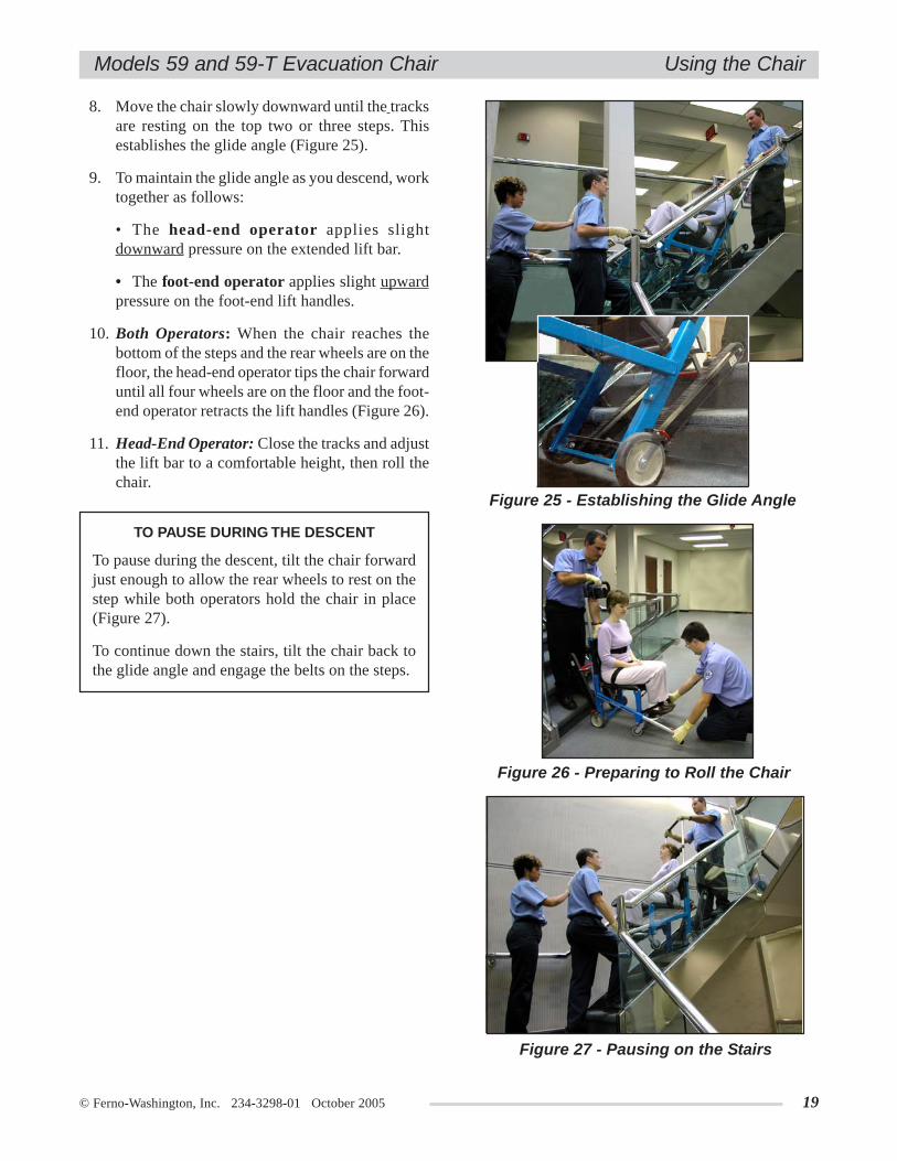
8. Move the chair slowly downward until the tracksare resting on the top two or three steps. Thisestablishes the glide angle (Figure 25).
9. To maintain the glide angle as you descend, worktogether as follows:
• The head-end operator applies slightdownward pressure on the extended lift bar.
• The foot-end operator applies slight upwardpressure on the foot-end lift handles.
10. Both Operators: When the chair reaches thebottom of the steps and the rear wheels are on thefloor, the head-end operator tips the chair forwarduntil all four wheels are on the floor and the foot-end operator retracts the lift handles (Figure 26).
11. Head-End Operator: Close the tracks and adjustthe lift bar to a comfortable height, then roll thechair.
Figure 25 - Establishing the Glide Angle
To pause during the descent, tilt the chair forwardjust enough to allow the rear wheels to rest on thestep while both operators hold the chair in place(Figure 27).
To continue down the stairs, tilt the chair back tothe glide angle and engage the belts on the steps.
TO PAUSE DURING THE DESCENT
Figure 26 - Preparing to Roll the Chair
Figure 27 - Pausing on the Stairs
20 © Ferno-Washington, Inc. 234-3298-01 October 2005
Models 59 and 59-T Evacuation ChairUsing the Chair
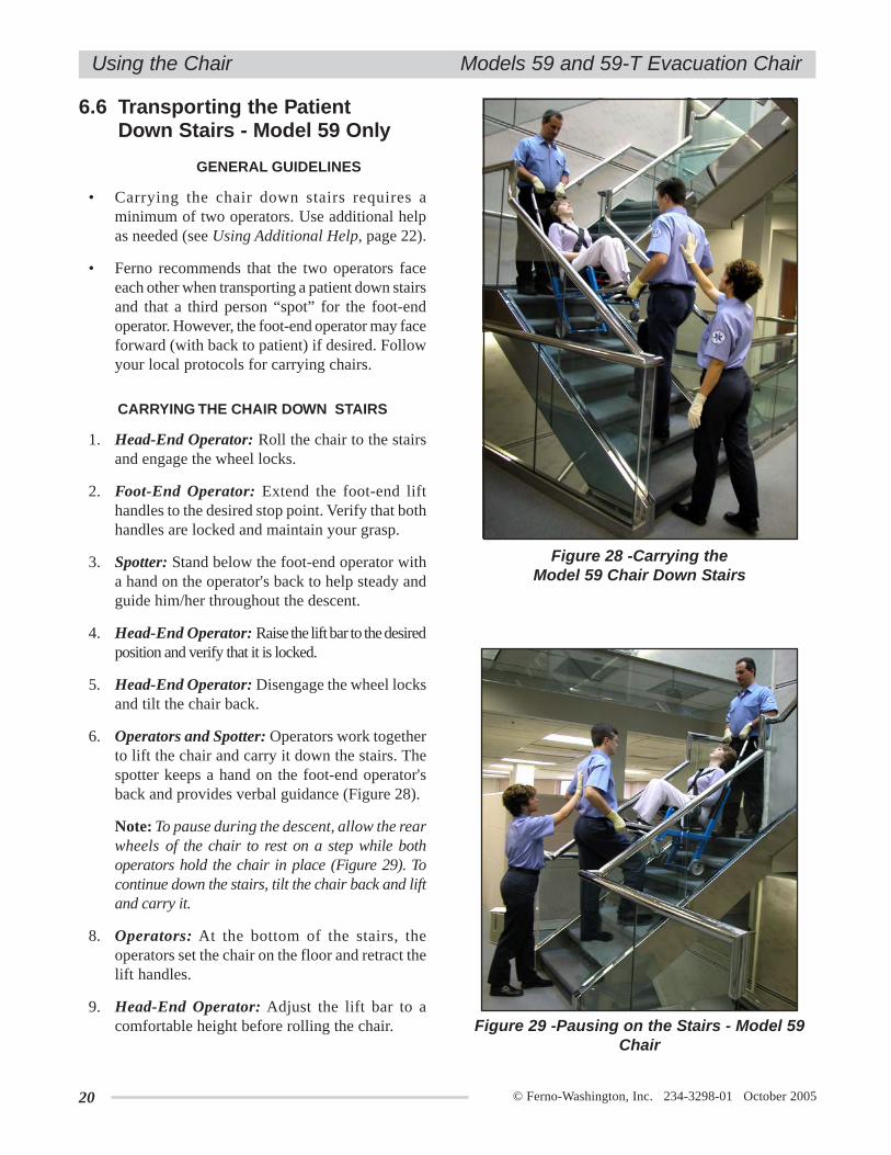
GENERAL GUIDELINES
• Carrying the chair down stairs requires aminimum of two operators. Use additional helpas needed (see Using Additional Help, page 22).
• Ferno recommends that the two operators faceeach other when transporting a patient down stairsand that a third person “spot” for the foot-endoperator. However, the foot-end operator may faceforward (with back to patient) if desired. Followyour local protocols for carrying chairs.
6.6 Transporting the PatientDown Stairs - Model 59 Only
CARRYING THE CHAIR DOWN STAIRS
1. Head-End Operator: Roll the chair to the stairsand engage the wheel locks.
2. Foot-End Operator: Extend the foot-end lifthandles to the desired stop point. Verify that bothhandles are locked and maintain your grasp.
3. Spotter: Stand below the foot-end operator witha hand on the operator's back to help steady andguide him/her throughout the descent.
4. Head-End Operator: Raise the lift bar to the desiredposition and verify that it is locked.
5. Head-End Operator: Disengage the wheel locksand tilt the chair back.
6. Operators and Spotter: Operators work togetherto lift the chair and carry it down the stairs. Thespotter keeps a hand on the foot-end operator'sback and provides verbal guidance (Figure 28).
Note: To pause during the descent, allow the rearwheels of the chair to rest on a step while bothoperators hold the chair in place (Figure 29). Tocontinue down the stairs, tilt the chair back and liftand carry it.
8. Operators: At the bottom of the stairs, theoperators set the chair on the floor and retract thelift handles.
9. Head-End Operator: Adjust the lift bar to acomfortable height before rolling the chair.
Figure 28 -Carrying theModel 59 Chair Down Stairs
Figure 29 -Pausing on the Stairs - Model 59Chair

© Ferno-Washington, Inc. 234-3298-01 October 2005 21
Models 59 and 59-T Evacuation Chair
6.7 Transporting the PatientUp Stairs -Models 59-T and 59
CARRYING THE CHAIR UP STAIRS
1. Head-End Operator: Roll the chair to the bottomof the stairs and position it with the patient’s backto the stairs.
2. Head-End Operator: Extend the lift bar to thedesired position and verify that it is locked.
3. Spotter: Stand above the head-end operator witha hand on the operator’s back to help steady andguide him/her throughout the ascent.
4. Foot-End Operator: Extend the foot-end lifthandles to the desired position and verify that bothhandles are locked Figure 30).
5. Both Operators and Spotter: Working together,the operators grasp the lift bar and lift handlesand carry the chair up the stairs. The spotter keepsa hand on the head-end operator’s back andprovides verbal guidance (Figure 31).
6. Both Operators: At the top of the stairs, the head-end operator sets the rear wheels of the chair onthe floor and rolls the chair backward until thefront wheels are securely on the floor.
7. Foot-end Operator: Retract the foot-end lifthandles.
8. Head-End Operator: Adjust the lift bar to acomfortable height before rolling the chair.
GENERAL GUIDELINES
• Carrying the chair up stairs requires a minimumof two operators. Use additional help as needed(see Using Additional Help, page 22).
• The two operators face each other whentransporting a patient up stairs. Fernorecommends that a third person “spot” for thehead-end operator. Follow your local protocolsfor carrying chairs.
Figure 30 - Preparing to Carry Model 59-T(Tracked) Chair Up Stairs.
Using the Chair
Figure 31 - Carrying the Model 59(Untracked) Chair Up Stairs
ImportantThe EZ Glide track system was designed toassist in descending stairs. It can be used toascend stairs, but in some circumstances it maybe easier to lift and/or carry the chair up stairs.

22 © Ferno-Washington, Inc. 234-3298-01 October 2005
Models 59 and 59-T Evacuation Chair
6.8 Using Additional Help
Operating the chair requires a minimum of two trained operators. Ferno recommends that the operators and helpersat opposite ends of the chair face each other when transporting a patient up or down stairs, and that a third trainedperson “spot” for the lead operator. However, all applicable local protocols for carrying chairs should be followed.
The trained operators should maintain control of the chair and operate the controls, and the designated lead operatorshould direct all helpers. The chart below shows suggested placement for operators and helpers.
Using the Chair
LOAD LIMIT
Inspect the chair if the loadlimit has been exceeded
(see Inspecting theChair, page 24).
500 lb227 kg
Key: O = Operator H = Helper S = Spotter P = Patient
TwoOperators
+Three
Helpers
TwoOperators
+One
Helper
DirectionGliding Down Stairs on Track System
orCarrying Chair Down Stairs
Carrying Chair Up Stairs
Direction
TwoOperators
+Two
HelpersP
O
HO
H
Rolling on Flat Surface
Helpers can cause injury or be injured.Maintain control of the chair, operate thecontrols, and direct all helpers.
WARNING!
© Ferno-Washington, Inc. 234-3298-01 October 2005 23
Models 59 and 59-T Evacuation Chair
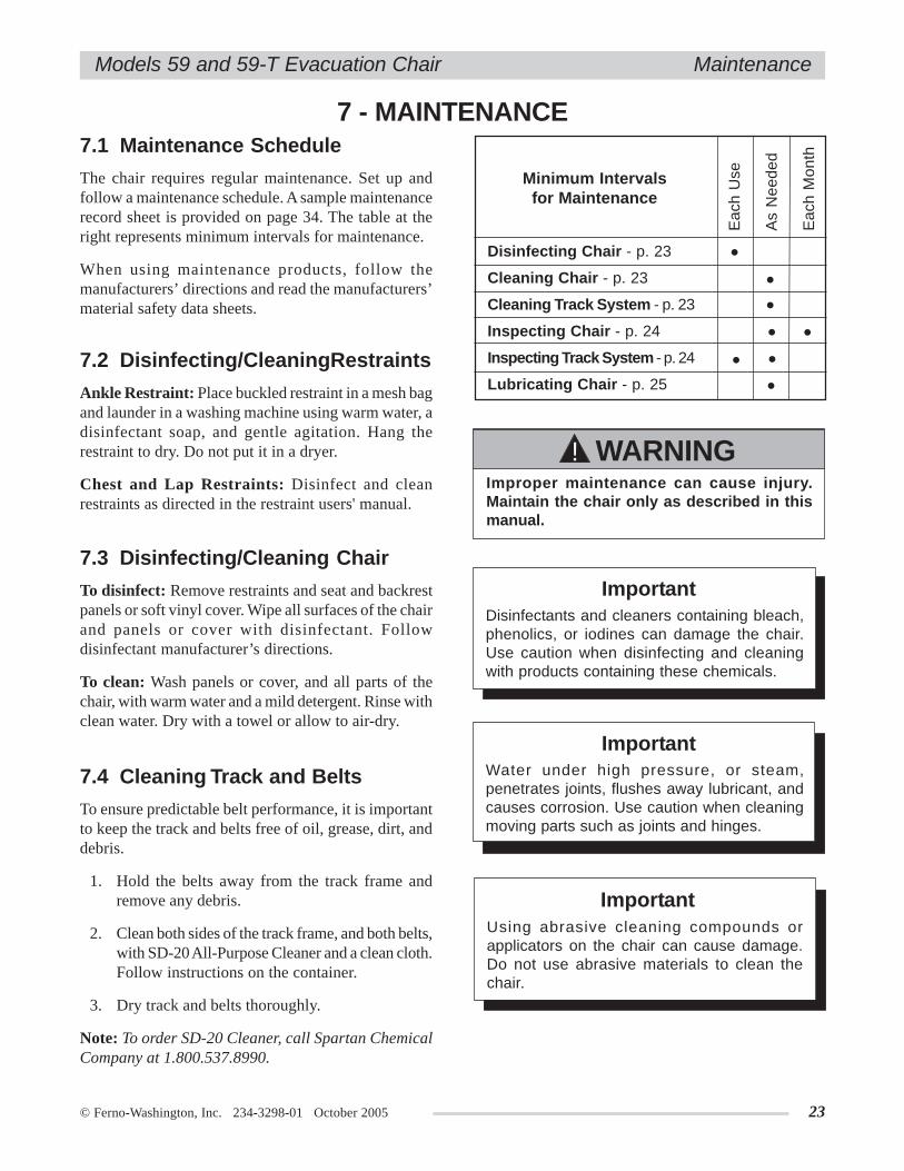
7 - MAINTENANCE7.1 Maintenance Schedule
The chair requires regular maintenance. Set up andfollow a maintenance schedule. A sample maintenancerecord sheet is provided on page 34. The table at theright represents minimum intervals for maintenance.
When using maintenance products, follow themanufacturers’ directions and read the manufacturers’material safety data sheets.
Maintenance
7.2 Disinfecting/CleaningRestraints
Ankle Restraint: Place buckled restraint in a mesh bagand launder in a washing machine using warm water, adisinfectant soap, and gentle agitation. Hang therestraint to dry. Do not put it in a dryer.
Chest and Lap Restraints: Disinfect and cleanrestraints as directed in the restraint users' manual.
Improper maintenance can cause injury.Maintain the chair only as described in thismanual.
WARNING!
7.3 Disinfecting/Cleaning Chair
To disinfect: Remove restraints and seat and backrestpanels or soft vinyl cover. Wipe all surfaces of the chairand panels or cover with disinfectant. Followdisinfectant manufacturer’s directions.
To clean: Wash panels or cover, and all parts of thechair, with warm water and a mild detergent. Rinse withclean water. Dry with a towel or allow to air-dry.
ImportantWater under high pressure, or steam,penetrates joints, flushes away lubricant, andcauses corrosion. Use caution when cleaningmoving parts such as joints and hinges.
ImportantUsing abrasive cleaning compounds orapplicators on the chair can cause damage.Do not use abrasive materials to clean thechair.
Minimum Intervalsfor Maintenance
•
•
Disinfecting Chair - p. 23
Cleaning Chair - p. 23
Cleaning Track System - p. 23
Inspecting Chair - p. 24
Inspecting Track System - p. 24
Lubricating Chair - p. 25
••
•
Eac
h U
se
As
Nee
ded
Eac
h M
onth
•
7.4 Cleaning Track and Belts
To ensure predictable belt performance, it is importantto keep the track and belts free of oil, grease, dirt, anddebris.
1. Hold the belts away from the track frame andremove any debris.
2. Clean both sides of the track frame, and both belts,with SD-20 All-Purpose Cleaner and a clean cloth.Follow instructions on the container.
3. Dry track and belts thoroughly.
Note: To order SD-20 Cleaner, call Spartan ChemicalCompany at 1.800.537.8990.
••
ImportantDisinfectants and cleaners containing bleach,phenolics, or iodines can damage the chair.Use caution when disinfecting and cleaningwith products containing these chemicals.

24 © Ferno-Washington, Inc. 234-3298-01 October 2005
Models 59 and 59-T Evacuation ChairMaintenance
7.5 Inspecting the Chair
Have your service’s equipment maintenance personnelinspect the chair at regular intervals. Track and trackbelts should be inspected after each use.
Follow the checklists on this page and work the chairthrough all its functions as described in this manual.
If inspection shows damage or excessive wear, removethe chair from service until repairs are made.
INSPECTION CHECKLIST
FOR MODEL 59-T AND MODEL 59 CHAIRS
Are all components present?
Is the chair free of excessive wear?
Are all screws, nuts, bolts, rivets, and roll pinssecurely in place?
Do all moving parts operate smoothly andproperly?
Do all locks on the chair operate properly?
Does the chair roll smoothly?
Are the restraints properly installed?
Is restraint webbing in good condition withno cuts or frayed edges?
Are restraint buckles free of visible damageand do they operate properly?
Do installed accessories operate properlywithout interfering with chair operation?
INSPECTION CHECKLIST
FOR TRACK AND BELTS
Are the track and belts free of lubricant, dirtand debris?
Is there visible damage to the track or belts?
Are inner cords of belts visible (indicating theneed for replacement)?
Are the belt-tensioning bolts and nuts tight?
Do the belts roll properly?
Do the track and belts perform properly?
© Ferno-Washington, Inc. 234-3298-01 October 2005 25
Models 59 and 59-T Evacuation Chair
Lubricating the track system can result ininjury to patient and/or operators. Neverlubricate the track or belts.
WARNING!
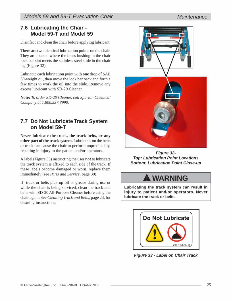
7.6 Lubricating the Chair -Model 59-T and Model 59
Disinfect and clean the chair before applying lubricant.
There are two identical lubrication points on the chair.They are located where the brass bushing in the chairlock bar slot meets the stainless steel slide in the chairleg (Figure 32).
Lubricate each lubrication point with one drop of SAE30-weight oil, then move the lock bar back and forth afew times to work the oil into the slide. Remove anyexcess lubricant with SD-20 Cleaner.
Note: To order SD-20 Cleaner, call Spartan ChemicalCompany at 1.800.537.8990.
Figure 32-Top: Lubrication Point Locations
Bottom: Lubrication Point Close-up
Figure 33 - Label on Chair Track
7.7 Do Not Lubricate Track Systemon Model 59-T
Never lubricate the track, the track belts, or anyother part of the track system. Lubricants on the beltsor track can cause the chair to perform unpredictably,resulting in injury to the patient and/or operators.
A label (Figure 33) instructing the user not to lubricatethe track system is affixed to each side of the track. Ifthese labels become damaged or worn, replace themimmediately (see Parts and Service, page 30).
If track or belts pick up oil or grease during use orwhile the chair is being serviced, clean the track andbelts with SD-20 All-Purpose Cleaner before using thechair again. See Cleaning Track and Belts, page 23, forcleaning instructions.
Maintenance

26 © Ferno-Washington, Inc. 234-3298-01 October 2005
Models 59 and 59-T Evacuation Chair
TOOLS NEEDED
2 ea ........................................... 7/16-inch Wrench1 ea ................................. #4 Phillips Screwdriver1 ea ............................... Ruler or Measuring Tape
TENSION-ADJUSTMENT
1. Open the track and lay the chair on its back on aworkbench as shown in Figure 34
OR
Stand the chair on its wheels on a workbench,then open the track and engage both wheel locks.
2. Loosen the bolt and black cap locking nutlocated at the top end of the track (Figure 35).
3. Slide the #4 Phillips screwdriver into theadjustment slot (Figure 35).
4. While one person tensions the belt by usingthe #4 Phillips screwdriver to pull the belt rollertoward the top of the track, the other personuses the two 7/16-inch wrenches to tighten thebolt and nut only enough to hold the tension(Figure 36).
7.8 Adjusting Track-Belt Tension
WHEN TO ADJUST BELT TENSION
Track belt tension needs to be adjusted when:
• a nut and bolt become loose• a belt pulls away from the track more than 1-1/
2 in. (3.8 cm) when measured using Method 1 onPage 27.
• a belt pulls away from the track more than 1 in.(2.5cm) when measured using Method 2 on Page 27.
Figure 35 - Belt Ready for Tensioning
Figure 36 - Tensioning the Belt
ImportantAdjusting the belt tension is a two-personoperation.
Figure 34 - Chair Positioned for TensioningProcedure. (See Step 1 for alternate position.)
LoosenedBolt
LoosenedBlack Cap
Locking Nut(not visible in photo)
#4 PhillipsScrewdriver in
AdjustmentSlot
Maintenance

© Ferno-Washington, Inc. 234-3298-01 October 2005 27
Models 59 and 59-T Evacuation Chair
5. There are two methods for checking belt tension. You can use whichever method you prefer, but do not usethe chair position from one method with the measurement range from the other method.
Use Method 1 (below, left) if the chair is laying on its tracks on a work bench. Use Method 2 (below, right)if the chair is standing on its wheels.
It may be necessary to repeat the tensioning and measuring one or more times to achieve the correct belttension.
6. When the belt tension is correct, finish tightening the bolt and nut to maintain the tension.
7. Repeat Steps 2-6 to adjust the tension of the other track belt.
Chair Must Be Laying on Its Tracks on a Work Bench
METHOD 1
Grasp the belt at the track midpoint and pull thebelt away from the track to remove any slack,then measure the distance between the exposedsurface of the track and the inner surface of thebelt. Take the measurement at the track midpoint.
The belt is correctly tensioned when themeasurement from the exposed surface of thetrack to the inner surface of the belt is 1-1/4 in.to 1-1/2 in. (3.175 cm to 3.8 cm), as in Figure 37.
Figure 37 - Checking Tension with Chair Laying on Its Tracks on a Work Bench
Maintenance
Chair Must Be Standing on Its WheelsMETHOD 2
Grasp the belt at the track midpoint and pull thebelt away from the track to remove any slack,then measure the distance between the exposedsurface of the track and the inner surface of thebelt. Take the measurement at the track midpoint.
The belt is correctly tensioned when themeasurement from the exposed surface of thetrack to the inner surface of the belt is 3/4 in. to 1in. (1.9 cm to 2.5 cm) as in Figure 38.
Figure 38 - Checking Tension with Chair Standing on Its Wheels

28 © Ferno-Washington, Inc. 234-3298-01 October 2005
Models 59 and 59-T Evacuation ChairMaintenance
7.9 Reconditioning the Track Belts
Track belts need reconditioning when the inner surfacebecomes glassy or glazed. As this glazing occurs, thebelts begin to move less freely over the steps and thebelt teeth begin to skip, rather than roll, over the steps.
ITEMS REQUIRED
FOR RECONDITIONING BELTS
• Permanent marker • 50-80 grit sandpaper • Wood block
To recondition the belts:
1. Place the chair on a workbench.
2. Apply wheel locks.
3. Roll the belt away from the track and mark theinner surface with a permanent marker to identifythe starting point for sanding (Figure 39).
4. Place sanding block between belt and track andmove the block up and down to sand the innersurface of the belt (Figure 40).
Note: Take care not to sand the surface of thetrack.
5. Repeat steps 3 and 4 with the other belt.
6. Secure a simulated patient weight to the chair andglide the chair down a flight of stairs to testwhether the belts roll over the steps properly.
If the belts do not perform properly, you may needto re-sand them, or they may need to be replaced.
Figure 40 - Sand in Direction of Arrows
Figure 39 - Marking the Starting Point forSanding the Belt
© Ferno-Washington, Inc. 234-3298-01 October 2005 29
Models 59 and 59-T Evacuation Chair
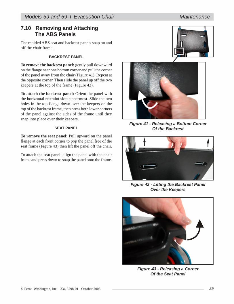
7.10 Removing and Attaching The ABS Panels
The molded ABS seat and backrest panels snap on andoff the chair frame.
BACKREST PANEL
To remove the backrest panel: gently pull downwardon the flange near one bottom corner and pull the cornerof the panel away from the chair (Figure 41). Repeat atthe opposite corner. Then slide the panel up off the twokeepers at the top of the frame (Figure 42).
To attach the backrest panel: Orient the panel withthe horizontal restraint slots uppermost. Slide the twoholes in the top flange down over the keepers on thetop of the backrest frame, then press both lower cornersof the panel against the sides of the frame until theysnap into place over their keepers.
SEAT PANEL
To remove the seat panel: Pull upward on the panelflange at each front corner to pop the panel free of theseat frame (Figure 43) then lift the panel off the chair.
To attach the seat panel: align the panel with the chairframe and press down to snap the panel onto the frame.
Figure 41 - Releasing a Bottom CornerOf the Backrest
Figure 42 - Lifting the Backrest PanelOver the Keepers
Figure 43 - Releasing a CornerOf the Seat Panel
Maintenance

30 © Ferno-Washington, Inc. 234-3298-01 October 2005
Models 59 and 59-T Evacuation Chair
7.11 Removing and Attaching The Soft Vinyl Seating
To remove the seating:
1. Unfasten the snap at each corner of the vinyl atthe top of the backrest (Figure 44).
2. Lay chair on its back and unbuckle both retainingstraps beneath the seat (Figure 45).
3. Unfasten the four snaps on the vinyl flap beneaththe seat at the front of the chair (Figure 46).
4. Lift the cover off the chair and return the chair tothe upright position.
To attach the seating:
1. Fasten the snap at each corner of the vinyl at thetop of the backrest.
2. Lay chair on its back and fasten the buckles ofboth retaining straps.
3. Fasten the four snaps on the vinyl flap beneaththe seat at the front of the chair.
4. Pull the free end of each buckled retaining strapuntil the strap is tight (Figure 47), then return thechair to the upright position.
Figure 44 - Unfasten Snaps
Figure 45 - Unbuckle Straps
Figure 46 - Unfasten Seat Snaps
Figure 47 - Tighten Straps
Maintenance
Snaps
Snaps

© Ferno-Washington, Inc. 234-3298-01 October 2005 31
Models 59 and 59-T Evacuation Chair
8 - ACCESSORIES AND RELATED PRODUCTSFerno offers a full line of emergency medical serviceaccessories (fasteners, IV poles, immobilizers, blankets,etc.). Selected items approved for use with the chairare listed here.
Always follow the instructions packed with accessories.Keep the instructions with this manual. Be aware ofany special considerations (loading heights, doorwidths, etc.) when using accessories.
For product information, contact Ferno CustomerRelations (page 34).
Attaching improper items to the chair cancause injury. Use only Ferno-approved itemson the chair.
WARNING!
8.1 EZ Glide Chair Accessories
Kwik Klip™ Restraint System ......................031-4002IV Bag Holder Complete ..............................082-1976
IV Bag Holder Replacement Strap ............082-1972Headrest Complete .......................................031-4000
Head Pad Replacement .............................082-1971Head Strap Replacement ...........................082-1970
Oxygen Cylinder Holder Complete ..............082-1977Oxygen Cylinder Replacement Straps ......031-3661
Non-Locking Rear Lift Handles, Pair ..........082-1974Non-Locking Rear Lift Handle, Right .........082-2008Non-Locking Rear Lift Handle, Left ...........082-2007Locking Rear Lift Handles, Pair ..................082-1975Locking Rear Lift Handle, Right .................082-2010Locking Rear Lift Handle, Left ....................082-2009Secure Mount Storage Brackets
(with spring release) ..................................082-2072Storage Bracket (with hooks) .......................082-2073Vinyl Storage Cover .....................................031-4023
Description Part #
Accessories
Ankle Restraint .............................................082-1973430 Restraint, 2-piece, 5 ft., black,
metal buckle ..............................................031-3892430 Restraint 2-piece, 7 ft., black,
metal buckle .............................................. 031-3911430-P Restraint 2-piece, 5-ft., black,
plastic buckle.............................................031-3797430-P Restraint, 2-piece, 7-ft., black,
plastic buckle.............................................031-3801416 Restraint, 2-piece, 5 ft., black,
metal rescue-style buckle ..........................031-3928416 Restraint, 2-piece, 7 ft., black,
metal rescue-style buckle ..........................031-3999Coated Restraint, 2-piece, 5 ft., green nonabsorbentstraps, metal buckle ........................................ E32032
Note: Models 430 and 430-P restraints also availablein 5- and 7-ft. lengths in burgundy or orange.
Description Part #
8.2 Restraints

32 © Ferno-Washington, Inc. 234-3298-01 October 2005
Models 59 and 59-T Evacuation ChairParts and Service
9 - PARTS AND SERVICE
9.1 Parts and Service - U.S.A. and Canada
In the United States, to order parts or for professionalrepair, contact EMSAR® - the only agent authorized byFerno to manage, service, and repair Ferno products.EMSAR factory-trained technicians use Ferno-approved parts and repair procedures. EMSAR has afranchise location serving you. For details, phone, fax,or visit EMSAR’s web site.
1.800.73.EMSAR (Phone)1.937.383.1051 (Fax)
www.EMSAR.com (Internet)
9.2 Parts and Service -Worldwide
To order Ferno parts and for professional repair, contactyour Ferno distributor. Your distributor is the only agentauthorized by Ferno to manage, service, and repairFerno products.
Improper parts and service can cause injury.Use only Ferno parts and Ferno-approvedservice on the chair.
WARNING!
Modifying the chair can cause injury anddamage. Use the chair only as designed byFerno.
WARNING!
Ref. # Description Part #
20 Telescoping handle assy, red ..................090-584221 Telescoping handle assy, orange ............090-584322 Telescoping handle assy, green ..............090-584423 Telescoping handle assy, platinum .........090-5845
(n/s) = not shown(n/v) = not visible in this photo
9.3 Parts List
Ref. # Description Part #
1 ABS Backrest panel ..................................190-14892 Track-close push handle ............................190-15003 ABS Seat panel .........................................190-14904 Seat bumper, pair w/hardware (n/v) ..........190-15015 Telescoping handle assy, blue ...................090-58376 Telescoping handle, grip only ...................190-14957 4" front caster, complete ...........................190-14948 Rear brake assy, right ................................090-58389 6" rear wheel w/hardware .........................190-149310 Ankle Restraint ........................................090-584011 Track lower roller w/hardware ...............190-149812 Rear brake assy, left (n/v) .......................090-583913 Track belt only ........................................190-149614 Track upper roller w/hardware ...............190-149715 Lift bar lock assy ....................................190-149216 Lift bar handle, complete .......................190-149117 Soft Vinyl Seating ..................................090-584118 Gas spring assy (n/v) ..............................190-149919 Label sheet and logo (n/s) ......................190-1502
© Ferno-Washington, Inc. 234-3298-01 October 2005 33
Models 59 and 59-T Evacuation Chair Parts and Service
3
7
14
2
9.4 Parts Diagrams
13
16
10
11
15
1
4
6
5
2322
2120
89
17

34 © Ferno-Washington, Inc. 234-3298-01 October 2005
Models 59 and 59-T Evacuation Chair
11 - FERNO CUSTOMER RELATIONS
10 - LIMITED WARRANTY
Warranty, Ferno Customer Relations
Serial Number ________________________
Limited Warranty Summary
Ferno products are warranted free from defects in material and workmanship for one year, except:
• External finishes (gelcoat, paint, powdercoat, decals, etc.) are warranted for 90 days.• Soft goods (webbing, vinyl, fabric, foam, etc.) are warranted for 90 days.• Fiberglass AquaCiser tanks are warranted against leakage for 5 years.• Stainless hydrotherapy tanks are warranted against tank shell leakage and corrosion for 5 years.• Mortuary products (except hydraulic parts and soft goods) are warranted for 2 years.• Ambulance cots and transporters (except external finish and soft goods) are warranted for 2 years.• EMS bags (replaceable bottom excluded) and backboards are warranted for lifetime replacement. (Damage caused byaccident, abuse, misuse or improper care will be repaired at a reasonable charge for which you will be informed prior to therepair work being done.)
Ferno repairs are warranted for 90 days from the date of repair.
This limited warranty applies only when the product is used as described in the instructions provided. The warranty periodbegins when the product is shipped from Ferno or when you receive it if you have proof of delivery. Shipping charges are notcovered by this limited warranty. Ferno is not liable for shipping damages or damages sustained through using the product.
Non-Ferno products sold by Ferno retain the product manufacturer’s original warranties. Ferno offers no warranties of anykind additional to those of the product manufacturer, nor does Ferno assume any liability for products manufactured by others.
Limited Warranty Obligation
If a product is proven defective, Ferno will repair or replace it, or, at our option, refund the item’s purchase price. In no eventis Ferno liable for more than the selling price of the product. The purchaser accepts these terms in lieu of all damages.
This is a summary of the limited warranty. The actual terms and conditions of the limited warranty, and the limitations ofliability and disclaimers, are available upon request by calling 800-733-3766 or 937-382-1451.
Customer service and product support are importantaspects of each Ferno product. For assistance, pleasecontact Ferno Customer Relations:
Please have the serial number of your EZ Glide Chairavailable when calling Ferno Customer Relations, andinclude it in all written communications.
Telephone (Toll-free) .......................... 1.877.733.0911Telephone ........................................... 1.937.382.1451Fax (Toll-free) .................................... 1.888.388.1349Fax ...................................................... 1.937.382.6569Internet ............................................... www.ferno.com

© Ferno-Washington, Inc. 234-3298-01 October 2005 35
Models 59 and 59-T Evacuation Chair Training and Maintenance Records
TRAINING RECORD Date Training MethodName
MAINTENANCE RECORD
ByDate Maintenance Performed


![[CREATING LABELS] MAKING TEXT DESIGNING LABELS … · [CREATING LABELS] MAKING TEXT DESIGNING LABELS PRINTING LABELS COMPLETED LABELS USEFUL FUNCTIONS USER'S GUIDE / Español Printed](https://img.dokumen.tips/doc/110x75/5e718e59f26dfc19d238892e/creating-labels-making-text-designing-labels-creating-labels-making-text-designing.jpg)