Embed Size (px)
Citation preview

User’sManual
IM 05J01B02-01E
GREEN SeriesUser’s Manual- Detailed Instruction -
IM 05J01B02-01E5th Edition


Toc-i
IM 05J01B02-01E 5th Edition : Mar.25,2005-00
CONTENTS
GREEN SeriesUser’s Manual- Detailed Instruction -
IM 05J01B02-01E 5th Edition
Ref.1.1: References Related to PV Input ................................................... Ref. 1-1Ref.1.1(1) Correcting the PV (1. Using PV input filter and PV input bias) ............ Ref. 1-1
Ref.1.1(2) Correcting the PV (2.Using ten-segment linearizer biasing orapproximation) .................................................................................... Ref. 1-4
Ref.1.1(3) Square-root extraction of PV ................................................................ Ref. 1-9
Ref.1.1(4) Changing the PV sampling period ...................................................... Ref. 1-11
Ref.1.1(5) Checking that the changed PV sampling period is appropriate ....... Ref. 1-14
Ref.1.1(6) Correcting the input value from a sensor .......................................... Ref. 1-16
Ref.1.1(7) Using PV tracking function (UT only) ................................................. Ref. 1-18
Ref.1.1(8) PV input range adjustment (When the UT/UP mode No. is 6, 7 or12 only) .............................................................................................. Ref. 1-21
Ref.1.2: References Related to Remote Input ......................................... Ref. 1-22Ref.1.2(1) Setting remote input units, range and scaling ................................... Ref. 1-23
Ref.1.2(2) Using square root extraction during remote input ............................ Ref. 1-27
Ref.1.2(3) Using remote setpoint filtering and ratio bias computing ................ Ref. 1-28
Ref.1.2(4) Tracking target setpoint when switching from remote to local control . Ref. 1-30
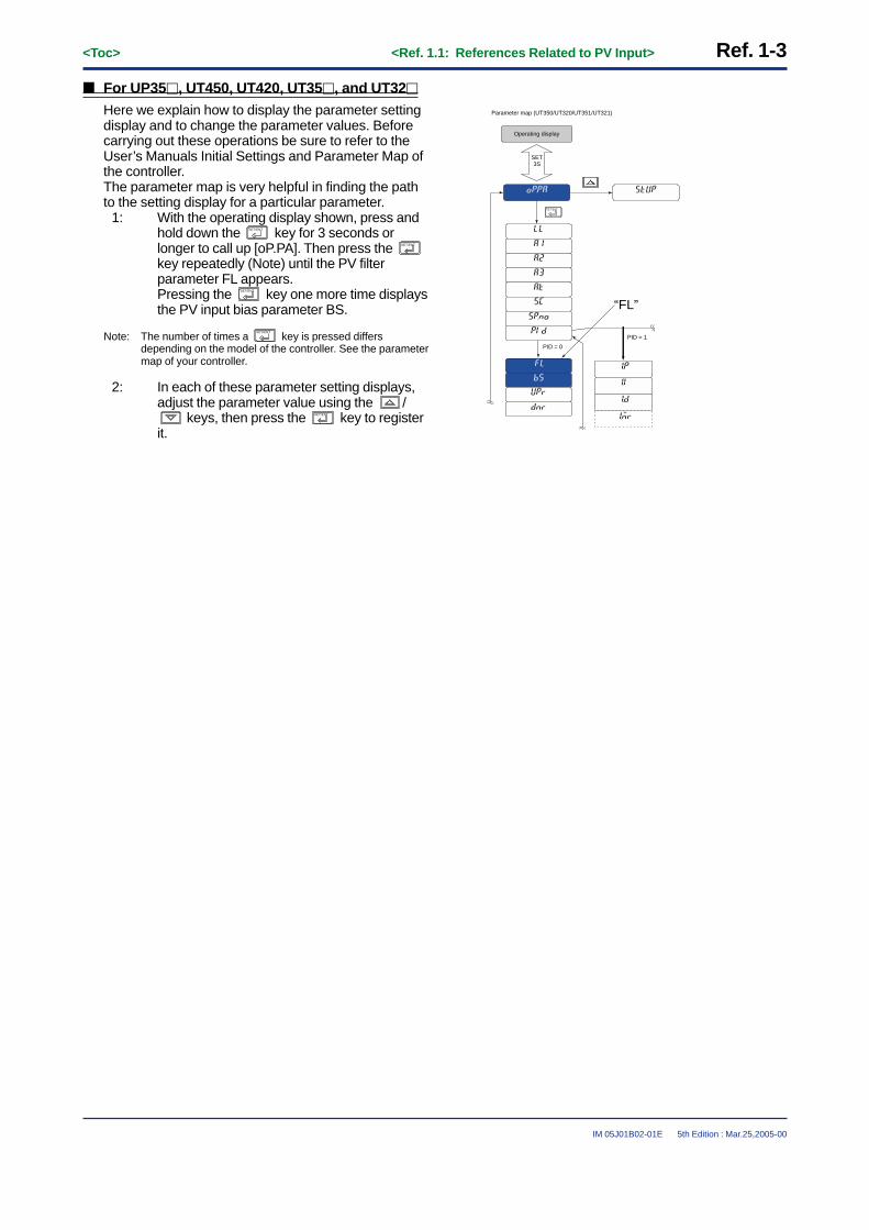
Ref.2.1: References Related to Control Output ........................................ Ref. 2-1Ref.2.1(1) Switching between Direct and Reverse Actions .................................. Ref. 2-2
Ref.2.1(2) Selecting PID Control Mode According to the Operating Condition .. Ref. 2-4
Ref.2.1(3) Using Control Output Limiter ............................................................... Ref. 2-8
Ref.2.1(4) Using Anti-reset Windup (Over-integration Prevention) Function ..... Ref. 2-9
Ref.2.1(5) Using “Super” (Overshoot Prevention) Function .............................. Ref. 2-10
Ref.2.1(6) Using “Super2” (Hunting Prevention) Function ................................ Ref. 2-11
Ref.2.1(7) Using Split-signal Computation / Output Function ........................... Ref. 2-13
Ref.2.1(8) Setting Preset Output Values .............................................................. Ref. 2-16
Ref.2.1(9) Placing Control Output in Tracking Mode (for CascadePrimary-loop Control or Loop Control for Backup) ........................ Ref. 2-18
Ref.2.1(10) Using Shutdown Function ................................................................ Ref. 2-19
Ref.2.2: References Related to Retransmission Output ........................ Ref. 2-20Ref.2.2(1) Changing the type of retransmission output signal .......................... Ref. 2-21
Ref.2.2(2) Retransmitting Program Pattern 2 (for UP750/UP550 only) .............. Ref. 2-23
Ref.2.2(3) Using the Loop Power Supply Function ............................................ Ref. 2-24

IM 05J01B02-01E
Toc-ii
5th Edition : Mar.25,2005-00
Ref.3.1: References Related to Contact Input ........................................... Ref. 3-1Ref.3.1(1) Changing contact input functions for the UT35h/UT32h .................... Ref. 3-2
Ref.3.1(2) Changing contact input functions for the UT450/UT420 .................... Ref. 3-5
Ref.3.1(3) Changing contact input functions for the UT550/UT551/UT520 ......... Ref. 3-9
Ref.3.1(4) Changing contact input functions for the UT750 .............................. Ref. 3-14
(4-1): Changing contact input terminal assignments of the UT750 ............ Ref. 3-14
(4-2): Using contact I/O expansion module with the UT750 ...................... Ref. 3-18
(4-3): Using Interrupt-message functions with the UT750 ......................... Ref. 3-20
(4-4): Using Interrupt-operating display functions with the UT750 ............. Ref. 3-22
Ref.3.1(5) Changing contact input functions for the UP35h ............................. Ref. 3-24
Ref.3.1(6) Changing contact input functions for the UP550 .............................. Ref. 3-26
Ref.3.1(7) Changing contact input functions for the UP750 ............................. Ref. 3-29
(7-1): Changing contact input functions for the UP750 .............................. Ref. 3-29
(7-2): Using contact I/O expansion module with the UP750 ...................... Ref. 3-34
(7-3): Using Interrupt-message functions with the UP750 ......................... Ref. 3-36
(7-4): Using Interrupt-operating display functions with the UP750 ............. Ref. 3-39
Ref.3.2: References Related to Contact Output ...................................... Ref. 3-40Ref.3.2(1) Changing Contact Output Functions for the UT750, UT550, UT551
and UT520 ......................................................................................... Ref. 3-41
(1) Single-loop control (UT mode 1) .......................................................... Ref. 3-44
(2) Cascade, primary-loop control (UT mode 2) ........................................ Ref. 3-45
(3) Cascade, secondary-loop control (UT mode 3) ................................... Ref. 3-45
(4) Cascade control (UT mode 4) ............................................................. Ref. 3-46
(5) Loop control for backup (UT mode 5) .................................................. Ref. 3-46
(6) Loop control with PV switching (UT mode 6) ....................................... Ref. 3-47
(7) Loop control with PV auto-selector (UT mode 7) ................................. Ref. 3-47
(8) Loop control with PV-hold function (UT mode 8) .................................. Ref. 3-48
(9) Dual-loop control (UT mode 11) .......................................................... Ref. 3-48
(10) Temperature and humidity control (UT mode 12) ............................... Ref. 3-48
(11) Cascade control with two universal inputs (UT mode 13) ................... Ref. 3-49
(12) Loop control with PV switching and two universal inputs (UT mode 14) .. Ref. 3-49
(13) Loop control with PV auto-selector and two universal inputs (UT mode 15) . Ref. 3-49
(14) Custom computation control (UT mode 21) ....................................... Ref. 3-49
Ref.3.2(2) Changing Contact Output Functions in the UP750 and UP550 ........ Ref. 3-50
(1) Single-loop control (UP mode 1) ......................................................... Ref. 3-51
(2) Cascade, primary-loop control (UP mode 2) ........................................ Ref. 3-52
(3) Cascade control (UP mode 4) ............................................................. Ref. 3-53
(4) Loop control with PV switching (UT mode 6) ....................................... Ref. 3-53
(5) Loop control with PV auto-selector (UP mode 7) ................................. Ref. 3-54
(6) Dual-loop control (UP mode 11) This function is for the UP750 only. .... Ref. 3-55
(7) Temperature and humidity control (UP mode 12)This function is for the UP750 only. .......................................... Ref. 3-55

Toc-iii
IM 05J01B02-01E 5th Edition : Mar.25,2005-00
(8) Cascade control with two universal inputs (UP mode 13) .................... Ref. 3-56
(9) Loop control with PV switching and two universal inputs (UP mode 14) .... Ref. 3-56
(10) Loop control with PV auto-selector and two universal inputs (UP mode 15) . Ref. 3-56
(11) Custom computation control (UP mode 21) ....................................... Ref. 3-56
Ref.3.2(3) Using the I/O Expansion Module with UT750 and UP750 .................. Ref. 3-57
Ref.3.3: References Related to Alarms ................................................... Ref. 3-62Ref.3.3(1) Setting Alarm Trigger Conditions ....................................................... Ref. 3-63
Ref.3.3(2) Setting Alarm hysteresis ON/OFF range ............................................ Ref. 3-65
Ref.3.3(3) Using the alarm timer (Control stable signal event) .......................... Ref. 3-67
Ref.3.3(4) Using the sensor ground alarm .......................................................... Ref. 3-70
Ref.3.3(5) Using the heater burnout alarm (UT35u and UT32u only) ................. Ref. 3-75
Ref.3.4: References Related to Instrument Alarms and Events ............. Ref. 3-77Ref.3.4(1) Using Instrument Alarms .................................................................... Ref. 3-78
Ref.3.4(2) Setting the Operating Conditions of Instrument Alarms ................... Ref. 3-83
Ref.3.4(3) Setting Hysteresis (On-off Bandwidth) of an Instrument Alarm ....... Ref. 3-84
Ref.3.4(4) Using the Sensor Ground Alarm......................................................... Ref. 3-86
Ref.3.4(5) Using PV Events .................................................................................. Ref. 3-90
Ref.3.4(6) Using Time Events .............................................................................. Ref. 3-97
Ref.3.4(7) Using Local Events ........................................................................... Ref. 3-101
Ref.4.1: References Related to Target Setpoints ...................................... Ref. 4-1Ref.4.1(1) Using Multiple Target Setpoints (8 Max.) .............................................. Ref. 4-2
Ref.4.1(2) Selecting PID selection method (Target SP selection, Zone PID orSelection by specified PID number)................................................. Ref. 4-10
Ref.4.1(3) Limiting Changes in Target Setpoints ................................................ Ref. 4-17
Ref.4.1(4) Setting ramp grades when switching between target setpoints ...... Ref. 4-18
Ref.5.1: References Related to Segment Operation ................................. Ref. 5-1Ref.5.1(1) Selecting Segment time between Time and Ramp time ...................... Ref. 5-1
Ref.5.1(2) Selecting PID control between Zone and Segment ............................. Ref. 5-7
Ref.5.2: References Related to Program Setup ...................................... Ref. 5-10Ref.5.2(1) Selecting Program Start Condition .................................................... Ref. 5-10
Ref.5.2(2) Using the Delayed Start Timer for Programmed Operation .............. Ref. 5-17
Ref.5.2(3) Selecting Segment-end Condition ..................................................... Ref. 5-18
Ref.5.2(4) Using the Wait Function ...................................................................... Ref. 5-24
Ref.5.2(5) Using the Hold Functions (Changing Segment Setpoint in Hold Status) Ref. 5-30
Ref.5.2(6) Using the Repeat Functions ............................................................... Ref. 5-34
Ref.5.2(7) Using the Advance Functions............................................................. Ref. 5-37
Ref.5.2(8) Signal Output at Program end ............................................................ Ref. 5-39
Ref.5.2(9) Operation in Local Mode (with Constant Target Setpoint) ................ Ref. 5-41
Ref.5.2(10) Starting the Program Operation at Any Segment ............................ Ref. 5-44
Ref.5.2(11) Operation with Linked Program Patterns (Pattern-link) .................. Ref. 5-46

IM 05J01B02-01E
Toc-iv
5th Edition : Mar.25,2005-00
Ref.5.3: Handy Features for Creating and Editing Programs................. Ref. 5-48Ref.5.3(1) Checking the Total Number of Unused Segments............................. Ref. 5-48
Ref.5.3(2) Checking the number of segments in a specific Program Pattern ... Ref. 5-50
Ref.5.3(3) Checking the number of all unused events ....................................... Ref. 5-51
Ref.5.3(4) Copying Program Patterns ................................................................. Ref. 5-53
Ref.5.3(5) Deleting Program Patterns ................................................................. Ref. 5-55
Ref.5.3(6) Adding (Inserting)/Deleting segments in Program Patterns ............. Ref. 5-57
Ref.6.1: References Related to Displays ................................................... Ref. 6-1Ref.6.1(1) Using SELECT Displays ........................................................................ Ref. 6-2
Ref.6.1(2) Changing Contents of Deviation Trend Display (for UP750, UP550and UT750 only) .................................................................................. Ref. 6-5
Ref.6.1(3) Changing Deviation Display Range of Deviation Monitor(for UT750, UT550, UT551 and UT450 only) ....................................... Ref. 6-7
Ref.7.1: References Related to Security ................................................... Ref. 7-1Ref.7.1(1) Setting a password to prevent unauthorized changes to
setup parameters ................................................................................ Ref. 7-1
Ref.7.1(2) Using the keylock function to prevent unauthorized key operation... Ref. 7-2
Ref.8.1: Outline of Registers and I - relays................................................ Ref. 8-1Ref.8.1(1) Outline of Registers and I - relays ........................................................ Ref. 8-2
Ref.8.1(2) D-register Outline and D-register Map ................................................. Ref. 8-3
UP750,UP550 D-register Map.................................................................... Ref. 8-4
UP35� D-register Map .............................................................................. Ref. 8-8
UT750, UT55�, UT520 D-register Map .................................................... Ref. 8-12
UT450,UT420 D-register Map .................................................................. Ref. 8-16
UT35�, UT32� D-register Map .............................................................. Ref. 8-19
Ref.8.1(3) B-register Outline and B-register Map ............................................... Ref. 8-23
UP750,UP550 B-register Map .................................................................. Ref. 8-24
Ref.8.1(4) I-relay Outline and I-relay Map ............................................................ Ref. 8-26
UP750, UP550 I-relay Map...................................................................... Ref. 8-28
Ref.8.1(5) I-relay Timer setting............................................................................. Ref. 8-33
Revision Information ............................................................................................ i

<Toc> <Ref. 1.1: References Related to PV Input> Ref. 1-1
IM 05J01B02-01E 5th Edition : Mar.25,2005-00
Ref.1.1: References Related to PV Input
IMPORTANT: Applicable models of this sectionUP750
UP750-��
UT750
UT750-��
UP550
UP550-��
UP35�
UP35�-��
UT5��
UT55�-��UT520-��
UT4�0
UT450-��UT420-��
UT3��
UT35�-��UT32�-��
UM3��
None
Note: The functions discussed in this section apply to all the models of UT and UP series.However, some of the functions are unavailable with certain models.Such models, if any, will be clearly noted in each of the following items from (1) to (8).
These sections provide references related to PV input, such as PV correction, listed below.
Only read the following descriptions if necessary and carry out the required operation.
(1) Correcting the PV (1. Using PV input filter and PV input bias)(2) Correcting the PV (2. Using ten-segment linearizer biasing or approximation)(3) Square-root extraction of PV(4) Changing the PV sampling period(5) Checking that the changed PV sampling period is appropriate(6) Correcting the input value from a sensor(7) Using PV tracking function (UT only)(8) PV input range adjustment (when the UT/UP mode No. is 6, 7 or 12 only)
<<Ref.1.1: References Related to PV Input>>Ref.1.1(1) Correcting the PV (1. Using PV input filter and PV input bias)
Filtering and biasing functions are available with all the UT/UP series models.
■ PV input filtering can be used to remove noise from a PV input that contains high frequency noise,such as flow rate and pressure signals.
The PV input filter provides first-order-lag computation.Setting a larger time constant (as a parameter value) can increase the amount of noise removed.This filtering is also used to improve controllability and for phase compensation.The time constant of the PV filter is offered as an operating parameter and can be changed during operation.
Actual input With a small time constant With a large time constant
Fig. 1-1-1

Ref. 1-2<Toc> <Ref. 1.1: References Related to PV Input>
IM 05J01B02-01E 5th Edition : Mar.25,2005-00
■ PV input biasing adds a constant bias value to the PV input value, and the result is used for thecontroller display and control computation.
+ =PV input value PV value inside the controllerPV input bias
In some cases, the measured value is smaller than the actual value by a constant amount due to the physicalcircumstances at the sensor point.For example, the ambient temperature inside a furnace is often measured instead of the material’s temperature.In such cases, add a constant value for biasing.When the PV value is within the allowable accuracy range but there is a dispersion in PV readings between otherequipment, it is possible to use this function for fine adjustment.
● The following parameters are used.• Operating parameters (Operation-related parameters): BS and FL
UP750UP550UT750Code
UP35�UT3��
Code
Setting range
-100.0 to 100.0% of input range span
OFF or 1 to 120 s
243, 273(Note1)
244, 274(Note2)
D-register No.
UT5��UT4�0
Code
FL
BS
Description
PV input bias
PV input filter
Default
0.0% of input range span
OFF (No filtering)
(BS) (BS)
(FL) (FL)
Note1: For dual-loop control of UP750 and UT750, the D-register number of loop-2 BS is 273.Note2: For dual-loop control of UP750 and UT750, the D-register number of loop-2 FL is 274.
To set the parameters, carry out the following steps.
■ For UP750, UP550, UT750, UT550, UT551, and UT520
Here we explain how to display the parameter settingdisplay and to change the parameter values. Beforecarrying out these operations be sure to refer to theUser’s Manuals Initial Settings and Parameter Map ofthe controller.The parameter map is very helpful in finding the path tothe setting display for a particular parameter.
1: Referring to the User’s Manual above, displaythe operating parameter main menu [LP1](Note1).Then, display the submenu [PAR].
Note1: If the UP/UT mode has been set for using loop-2 or thesecondary loop, also set the corresponding parameters underthe main menu [LP2] in the same way.
2: Press the SET/ENT key 3 times* to display the PVinput bias parameter BS. * Depends on the controller mode.Pressing the SET/ENT key one more time displaysthe PV input filter parameter FL.
3: In each of these parameter setting displays,adjust the parameter value using the /
keys, then press the SET/ENT key to register it.
SET3S
Operating display
Mainmenu
Sub menu
Parameter map (UT550/UT520)
U3U2U1
+
FLBSSCAT
RTDNRUPR
RFLRBS
ORHORB
ORL
LP1 LP2 USR
PAR 1.PID 7.PID 8.PID
Sameas
LP1
SET
SET
SET
1.A31.A21.A11.SP
1.I1.P1.A4
1.OH1.D
1.MR1.OL
1.H
1.Pc1.DR
1.Ic
1.Hc1.Dc
1.DB
1.PO1.RP
1.Oc
SET
7.A37.A27.A1
7.I7.P7.A4
7.OH7.D
7.MR7.OL
7.H
7.Pc7.DR
7.Ic
7.Hc7.Dc
7.DB
7.PORHY
7.Oc
SET
SET
8.A38.A28.A18.SP
8.I8.P8.A4
8.OH8.D
8.MR8.OL
8.H
8.Pc8.DR
8.Ic
8.Hc8.Dc
8.DB
8.PORDV
8.Oc
SET
MODE
MOD(C.A.M)
SPN
MOD(R/L)MOD(S/R)
orSET3S
+
7.SP
“BS”
<Toc> <Ref. 1.1: References Related to PV Input> Ref. 1-3
IM 05J01B02-01E 5th Edition : Mar.25,2005-00
■ For UP35�, UT450, UT420, UT35�, and UT32�
Here we explain how to display the parameter settingdisplay and to change the parameter values. Beforecarrying out these operations be sure to refer to theUser’s Manuals Initial Settings and Parameter Map ofthe controller.The parameter map is very helpful in finding the pathto the setting display for a particular parameter.
1: With the operating display shown, press andhold down the SET/ENT key for 3 seconds orlonger to call up [oP.PA]. Then press the SET/ENT
key repeatedly (Note) until the PV filterparameter FL appears.Pressing the SET/ENT key one more time displaysthe PV input bias parameter BS.
Note: The number of times a SET/ENT
key is pressed differsdepending on the model of the controller. See the parametermap of your controller.
2: In each of these parameter setting displays,adjust the parameter value using the /
keys, then press the SET/ENT key to registerit.
PID = 0
Operating display
Parameter map (UT350/UT320/UT351/UT321)
SET/ENTSET/ENT
PID = 1
SET3S
“FL”

Ref. 1-4<Toc> <Ref. 1.1: References Related to PV Input>
IM 05J01B02-01E 5th Edition : Mar.25,2005-00
<<Ref.1.1: References Related to PV Input>>Ref.1.1(2) Correcting the PV (2.Using ten-segment linearizer biasing or approximation)
Ten-segment linearizer biasing and approximation are available with UP750, UP550, UT750, UT550, UT551, andUT520.
Whether to use the biasing or approximation function is specified by the parameter 1.PMD (Note), which is set tospecify ten-segment linearizer biasing at the time of shipping.
As shown in the following “Operating parameters (Ten-segment linearizer input parameters)” table, the settingdisplay of parameter 1.PMD is located after the ten-segment linearizer input 1 to 11 and ten-segment linearizeroutput 1 to 11.
Note: • “1.PMD” is the parameter for UP750, UP550, and UT750.• “1.MD” is the parameter for UT550, UT551 and UT520.• “2.PMD” can also be used if the UP/UT mode is set for using loop-2 or the secondary loop.
→ For how to set the parameters required for the functions discussed here, see “■ Setting the Required Param-eters” in the end of this subsection.

<Toc> <Ref. 1.1: References Related to PV Input> Ref. 1-5
IM 05J01B02-01E 5th Edition : Mar.25,2005-00
■ Ten-segment Linearizer Biasing
This function is used to correct an input signal affected by sensor deterioration. The corrected values (b) areobtained by adding the corresponding bias values to each of the 11 points of optionally set input values (a).The input values used to configure the ten-segment linearizer are set with parameters 1.a1 to 1.a11 (Note). Thebias values (b-axis) for each of the input values (a) are set with parameters 1.b1 to 1.b11 (Note).
Note: • 1.a1 to 1.a11 and 1.b1 to 1.b11 are the parameters for UP750, UP550, and UT750.• 1.A1 to 1.AB and 1.B1 to 1.BB are the parameters for UT550, UT551 and UT520.• If the UP/UT mode is set for using loop-2 or the secondary loop, “2.a1 to 2.a11 and 2.b1 to 2.b11,” and “2.A1 to 2.AB and 2.B1 to
2.BB” can also be used.
Actual input
Ten-segment linearizer bias
Corrected value (the sum of actual input and bias values)
n.a2 n.a4 Input (a)
n.b4
Output (b)
Fig. 1-1-2 Ten-segment Linearizer Biasing
■ Ten-segment Linearizer Approximation
This function is used when the input signal and the required measurement signal have a non-linear relationship.For example, when trying to obtain the volume from a sphere tank level.As shown in the figure below, the output values (b) can be optionally set to 11 points of the optionally set inputvalues (a).The input values used to configure the ten-segment linearizer are set with parameters 1.a1 to 1.a11 (Note). Thecorrective values (b-axis) of ten-segment linearizer approximation for each of the input values (a) are set withparameters 1.b1 to 1.b11 (Note).
Note: • 1.a1 to 1.a11 and 1.b1 to 1.b11 are the parameters for UP750, UP550, and UT750.• 1.A1 to 1.AB and 1.B1 to 1.BB are the parameters for UT550, UT551 and UT520.• If the UP/UT mode is set for using loop-2 or the secondary loop, “2.a1 to 2.a11 and 2.b1 to 2.b11” and “2.A1 to 2.AB and 2.B1 to 2.BB”
can also be used.
Ten-segment linearizer approximation
Input (a)
Output (b)
Fig. 1-1-3 Ten-segment Linearizer Approximation

Ref. 1-6<Toc> <Ref. 1.1: References Related to PV Input>
IM 05J01B02-01E 5th Edition : Mar.25,2005-00
● The following parameters are used.• Operating parameters (Ten-segment Linealizer Parameters)
UP750UP550UT750Code
Description Setting range
-66.7% to 105.0% of PV input range
726
751
0.0% of PV input range
Default D-register No.
UT5��
Code
2.a1
1.a1 Ten-segment linearizer 1 input-1(1.A1)
2.A1 (for 2nd loop)
-66.7% to 105.0% of PV input range span (Note 2)
727
752
0.0% of PV input range span (Note 2)
2.b1
1.b1 Ten-segment linearizer 1 output-1(1.B1)
2.B1 (for 2nd loop)
-66.7% to 105.0% of PV input range
728
753
0.0% of PV input range
2.a2
1.a2 Ten-segment linearizer 1 input-2(1.A2)
2.A2 (for 2nd loop)
-66.7% to 105.0% of PV input range span (Note 2)
729
754
0.0% of PV input range span (Note 2)
2.b2
1.b2 Ten-segment linearizer 1 output-2(1.B2)
2.B2 (for 2nd loop)
-66.7% to 105.0% of PV input range
730
755
0.0% of PV input range
2.a3
1.a3 Ten-segment linearizer 1 input-3(1.A3)
2.A3 (for 2nd loop)
-66.7% to 105.0% of PV input range span (Note 2)
731
756
0.0% of PV input range span (Note 2)
2.b3
1.b3 Ten-segment linearizer 1 output-3(1.B3)
2.B3 (for 2nd loop)
-66.7% to 105.0% of PV input range
732
757
0.0% of PV input range
2.a4
1.a4 Ten-segment linearizer 1 input-4(1.A4)
2.A4 (for 2nd loop)
-66.7% to 105.0% of PV input range span (Note 2)
733
758
0.0% of PV input range span (Note 2)
2.b4
1.b4 Ten-segment linearizer 1 output-4(1.B4)
2.B4 (for 2nd loop)
-66.7% to 105.0% of PV input range
734
759
0.0% of PV input range
2.a5
1.a5 Ten-segment linearizer 1 input-5(1.A5)
2.A5 (for 2nd loop)
-66.7% to 105.0% of PV input range span (Note 2)
735
760
0.0% of PV input range span (Note 2)
2.b5
1.b5 Ten-segment linearizer 1 output-5(1.B5)
2.B5 (for 2nd loop)
-66.7% to 105.0% of PV input range
736
761
0.0% of PV input range
2.a6
1.a6 Ten-segment linearizer 1 input-6(1.A6)
2.A6 (for 2nd loop)
-66.7% to 105.0% of PV input range span (Note 2)
737
762
0.0% of PV input range span (Note 2)
2.b6
1.b6 Ten-segment linearizer 1 output-6(1.B6)
2.B6 (for 2nd loop)
-66.7% to 105.0% of PV input range
738
763
0.0% of PV input range
2.a7
1.a7 Ten-segment linearizer 1 input-7(1.A7)
2.A1 (for 2nd loop)
-66.7% to 105.0% of PV input range span (Note 2)
739
764
0.0% of PV input range span (Note 2)
2.b7
1.b7 Ten-segment linearizer 1 output-7(1.B7)
2.B7 (for 2nd loop)
(Note 1)
(Note 1)
(Note 1)
(Note 1)
(Note 1)
(Note 1)
(Note 1)
(Note 1)
(Note 1)
(Note 1)
(Note 1)
(Note 1)
(Note 1)
(Note 1)

<Toc> <Ref. 1.1: References Related to PV Input> Ref. 1-7
IM 05J01B02-01E 5th Edition : Mar.25,2005-00
-66.7% to 105.0% of PV input range
740
765
0.0% of PV input range
2.a8
1.a8 Ten-segment linearizer 1 input-8(1.A8)
2.A8 (for 2nd loop)
-66.7% to 105.0% of PV input range span (Note 2)
741
766
0.0% of PV input range span (Note 2)
2.b8
1.b8 Ten-segment linearizer 1 output-8(1.B8)
2.B8 (for 2nd loop)
-66.7% to 105.0% of PV input range
742
767
0.0% of PV input range
2.a9
1.a9 Ten-segment linearizer 1 input-9(1.A9)
2.A9 (for 2nd loop)
-66.7% to 105.0% of PV input range span (Note 2)
743
768
0.0% of PV input range span (Note 2)
2.b9
1.b9 Ten-segment linearizer 1 output-9(1.B9)
2.B9 (for 2nd loop)
-66.7% to 105.0% of PV input range
744
769
0.0% of PV input range
2.a10
1.a10 Ten-segment linearizer 1 input-10(1.AA)
2.AA (for 2nd loop)
-66.7% to 105.0% of PV input range span (Note 2)
745
770
0.0% of PV input range span (Note 2)
2.b10
1.b10 Ten-segment linearizer 1 output-10(1.BA)
2.BA (for 2nd loop)
-66.7% to 105.0% of PV input range
746
771
0.0% of PV input range
2.a11
1.a11 Ten-segment linearizer 1 input-11(1.AB)
2.AB (for 2nd loop)
-66.7% to 105.0% of PV input range span (Note 2)
747
772
0.0% of PV input range span (Note 2)
2.b11
1.b11 Ten-segment linearizer 1 output-11(1.BB)
2.BB (for 2nd loop)
0:Ten-segment linearizer biasing1:Ten-segment linearizer approximation (Note 2)
748
773
0:Ten-segment linearizer biasing
2.PMD
1.PMD Ten-segment linearizer 1 mode(1.MD)
2.MD (for 2nd loop)
UP750UP550UT750Code
Description Setting range Default D-register No.
UT5��
Code
(Note 1)
(Note 1)
(Note 1)
(Note 1)
(Note 1)
(Note 1)
(Note 1)
(Note 1)
(Note 1)
Note1: These parameters are used for loop-2 when the UP/UT mode is set for using loop-2 or the secondary loop.Note2: As shown in the table, at the time of shipping, the ten-segment linearizer mode parameter (1.PMD and others) is set to 0, which selects
biasing. In this mode, the ten-segment linearizer output parameters are bias values; therefore, their setting ranges at the time ofshipping are -66.7 to 105.0% of measurement range span.If the ten-segment linearizer mode is changed to 1, which selects approximation, the setting ranges of ten-segment linearizer outputparameters will be -66.7 to 105.0% of the PV input range (corrective values for approximation).

Ref. 1-8<Toc> <Ref. 1.1: References Related to PV Input>
IM 05J01B02-01E 5th Edition : Mar.25,2005-00
■ Setting the Required Parameters
To set the parameters, carry out the following steps.
Here we explain how to display the parameter setting display and to change the parameter values. Before carryingout these operations be sure to refer to the User’s Manuals Initial Settings and Parameter Map of the controller.The parameter map is very helpful in finding the path to the setting display for a particular parameter.
PYS1
1.b21.a21.b11.a1
1.a41.b31.a3
1.a51.b4
1.a61.b5
1.b6
1.b71.a7
1.a8
1.a91.b8
1.b9
1.b101.a10
1.a11
1.PMD1.b11
2.b22.a22.b12.a1
2.a42.b32.a3
2.a52.b4
2.a62.b5
2.b6
2.b72.a7
2.a8
2.a92.b8
2.b9
2.b102.a10
2.a11
2.PMD2.b11
USRLP2 PYS2PYS1 STUP
SETSET
LP1MODE
SET3S
Operation dilplay
Mainmenu
UT750's Parameter Map
“1.a1”
“1.PMD”
1: Referring to the User’s Manuals above, displaythe operating parameter main menu [PSY1](Note 1).
Note1: If the UP/UT mode has been set for using loop-2 or thesecondary loop, also set the corresponding parameters underthe main menu [PYS2] in the same way.
2: Press the SET/ENT key 23 times to display theparameter “1.PMD”. (Note2) And adjust the parameter value(0 or 1) usingthe / keys, then press the SET/ENT key toregister it.
Note2: “1.PMD” is the parameter for UP750, UP550 and UT750.“1.MD” is the parameter for UT550, UT551 and UT520.
3: Press the SET/ENT key once to display the param-eter main menu [PYS1], and thenpress SET/ENT key again to display the parameter“1.a1” (Note3).
Note3: “1.a1” is the parameter for UP750,UP550 and UT750.“1.A1” is the parameter for UT550, UT551 and UT520.
4: Thereafter, adjust the display value for eachparameter in the order shown in the parametertable above, using the / keys thenpress the SET/ENT key to register them.

<Toc> <Ref. 1.1: References Related to PV Input> Ref. 1-9
IM 05J01B02-01E 5th Edition : Mar.25,2005-00
<<Ref.1.1: Reference Related to PV Input>>Ref.1.1(3) Square-root extraction of PV
Square-root extraction is available with UP750, UP550, UT750, UT550, UT551 and UT520.
This calculation is used to convert, for example, a differential pressure signal from a throttling flow meter such asan orifice and nozzle into a flow-rate signal. A low signal cut off point can also be set.
100.0%
Input 100.0%0.0%
Slope = 1
Low signal cut off point (0.0 - 5.0%)
The low signal cut off point is set using parameter A.LC1 or other (see table below).
Fig. 1-1-4 Square-root Extraction
● The following parameters are used.• Setup parameters (Analog Input Computation Parameters)
UP750UP550UT750Code
Description Setting range
1003OFF
Default D-registerNo.
UT5��
Code
A.SR1 Analog input-1spuare-root computation
OFF or ON(ON: Compute the square root)
10041.0%A.LC1 Analog input-1low signal cutoff
0.0 to 5.0% of PV input range
1007OFFA.SR2(Note 1)
Analog input-2spuare-root computation
no function OFF or ON(ON: Compute the square root)
10081.0%A.LC2(Note 1)
Analog input-2low signal cutoff
no function 0.0 to 5.0% of PV input range
1011OFFA.SR3(Note 2)
Analog input-3spuare-root computation
OFF or ON(ON: Compute the square root)
10121.0%A.LC3(Note 2)
Analog input-3low signal cutoff
0.0 to 5.0% of PV input range
(SR1)
(LC1)
(SR3)
(LC3)
Note 1: These parameters are used for 2-loop type of UP750 or UT750. Not displayed for UP550, UT550, UT551 and UT520.Note 2: These parameters can be used when the controller has Remote input function.

Ref. 1-10<Toc> <Ref. 1.1: References Related to PV Input>
IM 05J01B02-01E 5th Edition : Mar.25,2005-00
■ Setting the Required Parameters
To set the parameters, carry out the following steps.
Here we explain how to display the parameter setting display and to change the parameter values. Before carryingout these operations be sure to refer to the User’s Manuals Initial Settings and Parameter Map of the controller.The parameter map is very helpful in finding the path to the setting display for a particular parameter.
1: Referring to the User’s Manuals above, displaythe Setup parameter main menu [CMLP].Then, display the submenu [AIN].
2: Press the SET/ENT key 3 times to display the param-eter “A.SR1”. (Note1)When you use the “Spuare-root extraction ofPV”, set the parameter value to “ON” using the
/ keys, then press the SET/ENT key toregister it.
Note1: “A.SR1” is the parameter for UP750, UP550 and UT750.“SR1” is the parameter for UT550, UT551 and UT520.
3: Press the SET/ENT key once to display the parameter“A.LC1”. (Note2)Set the “Analog input-1 low signal cutoff” ifnecessary.
Note2: “A.LC1” is the parameter for UP750, UP550 and UT750.“LC1” is the parameter for UT550, UT551 and UT520.
4: After the above operation, repeat the followingoperation if necessary.• Display the parameter setting display which
you want to set the value. (ex.“A.LC2”)• Adjust the parameter value using the /
keys, then press the SET/ENT key to registerit.
Mainmenu
Sub menu
A.LC1A.SR1A.FL1A.BS1
A.SR2A.FL2A.BS2
A.BS3A.LC2
A.SR3A.FL3
A.LC3
LOOP2LOOP1 CMLP
AIN RET TRND LOCK
RET2RTL1RTH1RET1
RTH2RTL2
TSC2TSC1DVB2DVB1
TTM
SETSETSET SET
OK
LP1MODE
A/M
PIDLP2
PYS1USR
PYS2PWD
�/�
SET DISP
Operation parameters display
Parametre Map
Password
(UT750)
CONF UTMD
DISP
“A.SR1”
TIPDescriptions of other parameters that belong to submenu AIN, such as parameter A.FL1, are given in “Ref. 1.1 (6)Correcting the Input Value from a Sensor” of this section. Refer to it as necessary.

<Toc> <Ref. 1.1: References Related to PV Input> Ref. 1-11
IM 05J01B02-01E 5th Edition : Mar.25,2005-00
<<Ref. 1.1: References Related to PV Input>>Ref.1.1(4) Changing the PV sampling period
CAUTIONWhen the controller is shipped, the PV sampling period is already set to values suitable for implementing themodel’s functions and specifications. Therefore, under normal conditions, the default sampling period shouldbe used with the controller and changing it to a shorter one may disable some of the controller’s functions.The sampling period should only be changed if you fully understand the procedures described in the followingsection.
CAUTIONThe response time in communication may be longer when change the PV sampling period shorter. In thiscase, reset the PV sampling period longer.
The PV sampling period can be changed with UP750, UP550, UT750, UT550, UT551 and UT520.
■ For UP750 and UP550 (Program Controllers)
The PV sampling period can be selected from 100 ms (the fastest), 200 ms, and 500 ms.(The factory-set default is 200 ms.)
■ For UT750, UT550, UT551 and UT520 (Digital Indicating Controllers)
The PV sampling period can be selected from 50 ms (the fastest), 100 ms, 200 ms, and 500 ms.(The factory-set default is 200 ms.)
The following tables show the limitations of controller functions for each value of the PV sampling period.
(1) UP750 (Program controller)
PV sampling period Limitations of controller functions
100 ms (the fastest) Possible with single-loop models (UP750-0�) when neither cascade control (UP mode = 4) nor custom computation function is used.
200 ms (factory-set default) Possible with single-loop models (UP750-0�) when cascade control is used.Possible with single-loop models (UP750-0�) and dual-loop models (UP750-5�) when about less than 50 custom computation modules are used. ← “50” is given as a rough guide (Note).
500 ms When 50 or more custom computation modules are used. ← “50” is given as a rough guide (Note).
Note: • To check that the selected PV sampling period is appropriate, use the setup parameter SMEC described later.• Set the PV sampling period as 200ms when the “SUPER 2” function is used.
Set the PV sampling period as 500ms when the “SUPER 2” function is used in Cascade control, dual loop control or Temperature andHumidity control mode.

Ref. 1-12<Toc> <Ref. 1.1: References Related to PV Input>
IM 05J01B02-01E 5th Edition : Mar.25,2005-00
(2) UP550 (Program controller)
PV sampling period Limitations of controller functions
100 ms (the fastest) Possible when cascade control (UP mode = 4) is not used and also none of the following functions are used. ← This is given as a rough guide (Note).• SUPER function • Heating/cooling control • PV input computation• Deviation alarm • Sensor grounding alarm • Self-diagnostic alarm• FAIL output • SP rate-of-change limiter • Output rate-of-change limiter
200 ms (factory-set default) When any of the functions prohibited (listed above) with a 100 ms sampling period are used.When Cascade control mode is used.
500 ms Note
Note: • To check that the selected PV sampling period is appropriate, use the setup parameter SMEC described later.• Set the PV sampling period as 200ms when the “SUPER 2” function is used.
Set the PV sampling period as 500ms when the “SUPER 2” function is used in Cascade control, dual loop control or Temperature andHumidity control mode.
(3) UT750 (Digital indicating controller)
PV sampling period Limitations of controller functions
50 ms (the fastest) Possible with UT750-00 (single-loop model with no optional specification) when single-loop control (UT mode = 1) is used and none of the following functions are used. ← This is given as a rough guide (Note).• SUPER function • Heating/cooling control • PV input computation• Deviation alarm • Sensor grounding alarm • Self-diagnostic alarm• FAIL output • SP rate-of-change limiter • Output rate-of-change limiter
100 ms Possible with single-loop models (UT750-0�) when cascade control (UP mode = 4) is not used. Possible with position-proportional models (UT750-1�). ← This is given as a rough guide (Note).
200 ms (factory-set default) Possible with single-loop models (UT750-0�) when cascade control is used.Possible with single-loop models (UT750-0�) and dual-loop models (UT750-5�) when about less than 50 custom computation modules are used. ← “50” is given as a rough guide (Note).
500 ms When 50 or more custom computation modules are used. ← “50” is given as a rough guide (Note).
Note: • To check that the selected PV sampling period is appropriate, use the setup parameter SMEC described later.• Set the PV sampling period as 200ms when the “SUPER 2” function is used.
Set the PV sampling period as 500ms when the “SUPER 2” function is used in Cascade control, dual loop control or Temperature andHumidity control mode.
(4) UT550, UT551, UT520 (Digital indicating controller)
PV sampling period Limitations of controller functions
50 ms (the fastest) Possible with UT5�� (single-loop model with no optional specification) when single-loop control (UT mode = 1) is used and none of the following functions are used. ← This is given as a rough guide (Note).• SUPER function • Heating/cooling control • PV input computation• Deviation alarm • Sensor grounding alarm • Self-diagnostic alarm• FAIL output • SP rate-of-change limiter • Output rate-of-change limiter
100 ms Possible when cascade control (UP mode = 4) is not used and any of the fumctions prohibited (listed above) with a 100ms sampling period are used.
200 ms (factory-set default) When cascade control mode is used.
500 ms Note
Note: • To check that the selected PV sampling period is appropriate, use the setup parameter SMC described later.• Set the PV sampling period as 100ms when the “SUPER 2” function is used.
Set the PV sampling period as 200ms when the “SUPER 2” function is used in Cascade control.
● The following parameters are used• Setup parameters (UP Mode/UT Mode parameters):SMP
UP750UP550UT750Code
Description Setting range
1281(UP mode)1181(UT mode)
200
Default D-registerNo.
UT5��
Code
SMP PV sampling period settig
50 (Note1), 100, 200or 500(SMP)
(Note 2)(Note 2)
Note 1: Only UT750, UT550, UT551 and UT520 can select “50ms”.Note 2: The D-register No. of UP750, UP550 (UP mode) is 1281 and the No. of UT750, UT5�� is 1181.

<Toc> <Ref. 1.1: References Related to PV Input> Ref. 1-13
IM 05J01B02-01E 5th Edition : Mar.25,2005-00
■ Setting the Required Parameters
To set the parameters, carry out the following steps.
Here we explain how to display the parameter setting display and to change the parameter values. Before carryingout these operations be sure to refer to the User’s Manuals Initial Settings and Parameter Map of the controller.The parameter map is very helpful in finding the path to the setting display for a particular parameter.
1: Referring to the User’s Manual above,display the setup parameter main menu[UTMD].Then, display the submenu [MD].
2: Press the SET/ENT key 2 times to display theparameter “SMP”.
3: In the parameter setting displays, adjustthe parameter value using the /
keys, then press the SET/ENT key toregister it.
P.UN1
SMECSMPUTM
P.RL1P.RH1P.DP1
P.DP2P.UN2
P.RL2P.RH2
IN3
RL3RH3UNI3
SH3SDP3
BSL3SL3
LOOP1
MD IN OUT VALV
RL1RH1UNI1IN1
SDP1
RJC2
CT1CT2
OT2OT1
BSL1SL1SH1
RJC1
RL2RH2UNI2IN2
SDP2
BSL2SL2SH2
AO2AO1CTc2CTc1
AO3A1H
A3HA2LA2HA1L
A3L
SETSET
R485
STP1PRI1BPS1PSL1
RP.T2
PSL2RP.T1ADR1DLN1
BPS2
ADR2DLN2STP2PRI2
SETSET
TR.TV.HV.L
V.MOD
V.RS
INIT
SET
TEST
INI
SET DISP
Password
CONF UTMDLOOP2 CMLP
SET
Parameter map (UT750)
“SMP”

Ref. 1-14<Toc> <Ref. 1.1: References Related to PV Input>
IM 05J01B02-01E 5th Edition : Mar.25,2005-00
<<Ref. 1.1: References Related to PV Input>>Ref.1.1(5) Checking that the changed PV sampling period is appropriate
CAUTIONWhen you have changed the PV sampling period according to “Ref. 1.1 (4) Changing the PV sampling period”in this section, be sure to check that the new period is appropriate by referring to the following descriptions.
It is necessary to check the new period with UP750, UP550, UT750, UT550, UT551 and UT520 after the PVsampling period has been changed.
It is possible to check whether or not the currently set PV sampling period is appropriate for the controller toperform its required functions.For example, with UT550, the PV sampling period can be selected from 4 periods as shown in Table 1-1-1.However, some of the controller functions will be restricted under the use of each period.Although these limitations are given as “Limitations of controller functions” in “Ref. 1.1 (4) Changing the PVsampling period”, they should be taken only as rough guides.Therefore, you must check whether or not the period is appropriate before you use the controller.Carry out thischeck at the time of the operation test of the system that uses the controller.
This check is performed by monitoring the sampling error counter.The counter value shows how many times the controller failed to process its operation at the current PV samplingperiod.(The controller increments the counter value by 1 per 10 ms of control period delay when it cannot executeall the processing within the specified period.)
Processing
PV sampling period
30ms
Processing Processing
This chart shows that processing cannot be executed within the specified sampling period. In this example, the processing is delayed by 30 ms so the sampling error counter is incremented by 3.
Fig. 1-1-5 PV Sampling Period
If the counter value is not “0,” it means that some of the processing of the controller remains unprocessed.For this reason, if an exact control is required, set the sampling period so that the counter value will not increaseunless a long time has elapsed.If the counter value increases in a short period of time, change the sampling period to a larger value.You can monitor the counter value through the display of setup parameter SMEC (or SMC for UT5��) as shownin the following.

<Toc> <Ref. 1.1: References Related to PV Input> Ref. 1-15
IM 05J01B02-01E 5th Edition : Mar.25,2005-00
Table 1-1-1
PV sampling period Limitations of UT750 functions
50 ms (the fastest) Possible with UT750-00 (single-loop model with no optional specification) when single-loop control (UT mode = 1) is used and none of the following functions are used. ← This is given as a rough guide (Note).• SUPER function • Heating/cooling control • PV input computation• Deviation alarm • Sensor grounding alarm • Self-diagnostic alarm• FAIL output • SP rate-of-change limiter • Output rate-of-change limiter
100 ms Possible with single-loop models (UT750-0�) when cascade control (UP mode = 4) is not used. Possible with position-proportional models (UT750-1�). ← This is given as a rough guide (Note).
200 ms (factory-set default) Possible with single-loop models (UT750-0�) when cascade control is used.Possible with single-loop models (UT750-0�) and dual-loop models (UT750-5�) when about less than 50 custom computation modules are used. ← “50” is given as a rough guide (Note).
500 ms When 50 or more custom computation modules are used. ← “50” is given as a rough guide (Note).
Note: • To check that the selected PV sampling period is appropriate, use the setup parameter SMEC described later.• Set the PV sampling period as 200ms when the “SUPER 2” function is used.
Set the PV sampling period as 500ms when the “SUPER 2” function is used in Cascade control, dual loop control or Temperature andHumidity control mode.
● The following parameters are used.• Setup parameters (UP Mode / UT Mode Parameters): SMEC (SMC)
UP750UP550UT750Code
Description Setting range
320 (Note)
Default D-registerNo.
UT5��
Code
SMEC Sampling period error counter
0 to 30000 (Note)
(SMC)
Note: Since parameter SMEC is display only, it has no setting range.When the controller is powered on for the first time, the error counter value is 0. The counter value displayed can increase up to 30000as errors occur. Turning the power off resets the counter value to 0.
■ Setting the Required Parameters
To check that the selected PV sampling period is appropriate.
Here we explain how to display the parameter setting display and to change the parameter values. Before carryingout these operations be sure to refer to the User’s Manuals Initial Settings and Parameter Map of the controller.The parameter map is very helpful in finding the path to the setting display for a particular parameter.
1: Referring to the User’s Manual above,display the setup parameter main menu[UTMD].Then, display the submenu [MD].
2: Press the SET/ENT key 3 times to display theparameter “SMEC”, and check the countervalue.
Note1: “SMC” is the parameter for UT550, UT551 and UT520.
P.UN1
SMECSMPUTM
P.RL1P.RH1P.DP1
P.DP2P.UN2
P.RL2P.RH2
IN3
RL3RH3UNI3
SH3SDP3
BSL3SL3
LOOP1
MD IN OUT VALV
RL1RH1UNI1IN1
SDP1
RJC2
CT2CT1OT2OT1
BSL1SL1SH1
RJC1
RL2RH2UNI2IN2
SDP2
BSL2SL2SH2
AO2AO1CTc2CTc1
AO3
SETSET
R485
STP1PRI1BPS1PSL1
RP.T2
PSL2RP.T1ADR1DLN1
BPS2
ADR2DLN2STP2PRI2
SETSET
TR.TV.HV.L
V.MOD
V.RS
INIT
SET
TEST
INI
SET DISP
CONF UTMDLOOP2 CMLP
SET
A1H
A3HA2LA2HA1L
A3L
Password
Parameter map (UT750)
“SMEC”

Ref. 1-16<Toc> <Ref. 1.1: References Related to PV Input>
IM 05J01B02-01E 5th Edition : Mar.25,2005-00
<<Ref. 1.1: References Related to PV Input>>Ref.1.1(6) Correcting the input value from a sensor
CAUTIONThe “analog input bias” and “analog input filter” described here are similar to the functions described in “Ref.1.1 (1) Correcting the PV (1. Using PV filter and PV bias)” of this section.To use the PV filter and PV bias, operating parameters FL and BS are used. As they are operating param-eters, their settings can be changed during operation. Therefore, it is recommended that under normalcircumstances you use FL and BS.As for “analog input bias” and “analog input filter,” read the following description and only set them if neces-sary.
Sensor input value correction is available with UP750, UP550, UT750, UT550, UT551 and UT520.
Analog input bias is used to correct sensor-input characteristics, compensating lead wire errors, and so on.Normally, the PV biasing (BS) is convenient as mentioned in the CAUTION above, however, use the analog inputbias (A.BS) in cases where a constant correction is required due to sensor deterioration or for other reasons.Since this biasing is set using a setup parameter, it is suitable for input correction where once the parameter is set,it will not be changed for a long time.
The analog input filter is used to remove noise from a PV input signal that contains high frequency noise such asflow rate and pressure signals.This filter provides a first-order-lag calculation, which can remove more noise the larger the time constant be-comes (see the figure below).However, an excessively large time constant will distort the waveform. (See the figure below)As mentioned in the CAUTION above, a similar effect can be obtained by using the PV filter (FL).However, an analog input filter should be used in the cases where a constant level of correction is required, suchas in an environment that contains a lot of noise.
Actual input With a small time constant With an excessively large time constant
Fig. 1-1-6 Image of PV Input Correction by Analog Input Filter

<Toc> <Ref. 1.1: References Related to PV Input> Ref. 1-17
IM 05J01B02-01E 5th Edition : Mar.25,2005-00
● The following parameters are used.• Setup parameters (Analog Input Computation Parameters) : A.BS1, A.FL1, etc.
UP750UP550UT750Code
Description Setting range
10010.0% of input range span
Default D-registerNo.
UT5��
Code
A.BS1 Analog input 1bias
-100.0% to 100.0% of input range span
1002OFF(no filter)
A.FL1 Analog input 1filter
OFF or 1 to 120 (sec)
10050.0% of input range span
A.BS2(Note1)
Analog input 2bias
no function -100.0% to 100.0% of input range span
1006OFF(no filter)
A.FL2(Note1)
Analog input 2filter
no function OFF or 1 to 120 (sec)
10090.0% of input range span
A.BS3(Note2)
Analog input 3bias
-100.0% to 100.0% of input range span
1010OFF(no filter)
A.FL3(Note2)
Analog input 3filter
OFF or 1 to 120 (sec)
(BS1)
(FL1)
(BS3)
(FL3)
Note 1: These parameters are used for 2-loop type of UP750 or UT750. Not displayed for UP550, UT550, UT551 and UT520.Note 2: These parameters can be used when the controller has Remote input function.
■ Setting the Required Parameters
To set the parameters, carry out the following steps.
Here we explain how to display the parameter setting display and to change the parameter values. Before carryingout these operations be sure to refer to the User’s Manuals Initial Settings and Parameter Map of the controller.The parameter map is very helpful in finding the path to the setting display for a particular parameter.
1: Referring to the User’s Manual above,display the setup parameter main menu[CMLP].Then, display the submenu [AIN].
2: Press the SET/ENT key once to display theparameter “A.BS1”. (Note1)Adjust the parameter value using the /
keys, then press the SET/ENT key toregister it.
Note1: “A.BS1” is the parameter for UP750,UP550 and UT750.“BS1” is the parameter for UT550, UT551 and UT520.
3 : Press the SET/ENT key once to display theparameter “A.FL1”. (Note2)Set the “Analog input-1 filter” if necessary.
Note2: “A.FL1” is the parameter for UP750,UP550 and UT750.“FL1” is the parameter for UT550, UT551 and UT520.
4: After the above operation, repeat thefollowing operation if necessary.• Display the parameter setting display
which you want to set the value.(ex.“A.BS2”)
• Adjust the parameter value using the/ keys, then press the SET/ENT key
to register it.
Mainmenu
Sub menu
A.LC1A.SR1A.FL1A.BS1
A.SR2A.FL2A.BS2
A.BS3A.LC2
A.SR3A.FL3
A.LC3
LOOP2LOOP1 CMLP
AIN RET TRND LOCK
RET2RTL1RTH1RET1
RTH2RTL2
TSC2TSC1DVB2DVB1
TTM
SETSETSET SET
OK
LP1MODE
A/M
PIDLP2
PYS1USR
PYS2PWD
�/�
SET DISP
Operation parameter'sSetting display
CONF UTMD
DISP
Password
Parameter map (UT750)
“A.BS1”
TIPDescriptions of other parameters that belong to submenu AIN, such as parameter A.SR1, are given in “Ref.1.1 (3) Square-root extraction of PV” of this section. Refer to it as necessary.

Ref. 1-18<Toc> <Ref. 1.1: References Related to PV Input>
IM 05J01B02-01E 5th Edition : Mar.25,2005-00
<<Ref. 1.1: References Related to PV Input>>Ref.1.1(7) Using PV tracking function (UT only)
The PV tracking function is available with UT750, UT550, UT551. UT520, UT450, and UT420.
PV tracking is used to prevent a sudden change in PV.
Note: As shown below, PV tracking is turned OFF at the time of shipment. Turn it ON if necessary.
When PV tracking is ON, the controller sets the SP equal to PV temporarily in the event of the following:
• Power-on• Switching from MAN to AUTO mode• Switching from STOP to RUN• Switching the number of setpoint (SP No.)
After SP is equalized to PV, the SP is gradually changed toward the original SP value at a constant rate-of-change(for ramp rate; see the CAUTION below and the following Fig. 1-1-7).
CAUTIONThe SP rate-of-change (ramp rate) is set using parameter UPR and/or DNR, which is set to OFF at the time ofshipment. To use PV tracking, you must set parameter UPR and/or DNR to a desired ramp rate value.→ See “Ref.4.1(4) Changing SP at a ramp rate when SP is switched” in Ref. 4-1: References Related to TargetSetpoint (SP).With these parameters OFF, which specifies no ramp rate (ramp rate = 0), PV tracking will not operate.

<Toc> <Ref. 1.1: References Related to PV Input> Ref. 1-19
IM 05J01B02-01E 5th Edition : Mar.25,2005-00
● PV tracking enabled
MAN AUTO MAN AUTO
● PV tracking disabled
SP ramp-rate(UPR or DNR)
PV
SP
PV
SP
Time Timemode change mode change
Fig. 1-1-7 PV tracking function
● The following parameters are used.• Setup parameters (Target Setpoint-related Parameters) : PVT
UP750UP550UT750Code
Description Setting range
903(for loop-1)943(for loop-2)
OFF
Default D-registerNo.
UT5��UT4�0
Code
PVT PV tracking selection OFF or ON
(PVT) (Note1)
Note 1: This parameter is used for loop-2 when the UP/UT mode is set for using loop-2 or secondary loop.
■ Setting the Required Parameters
To use the PV tracking function (to turn ON/OFF the PV tracking function), carry out the operation shown below.
Since the operation differs between UT750/UT550/UT551/UT520 and UT450/UT420, instructions will be givenseparately in [1] and [2]. Follow either of them according to your controller’s model.

Ref. 1-20<Toc> <Ref. 1.1: References Related to PV Input>
IM 05J01B02-01E 5th Edition : Mar.25,2005-00
[1] UT750, UT550, UT551, UT520
To set the parameters, carry out the following steps.
Here we explain how to display the parameter setting display and to change the parameter values. Before carryingout these operations be sure to refer to the User’s Manuals Initial Settings and Parameter Map of the controller.The parameter map is very helpful in finding the path to the setting display for a particular parameter.
1: Referring to the User’s Manual above,display the setup parameter main menu[LOOP1] (Note1).Then, display the submenu [SP].
Note 1: To set PVT for loop-2, go to the main menu [LOOP2],then the submenu [SP] and carry out the same proce-dure.
2: Press the SET/ENT key 3 times (Note 2) todisplay the parameter “PVT”. And adjust the parameter value (OFF orON) using the / keys, then pressthe SET/ENT key to register it. (When “ON” isset, PV tracking operate.)
Note 2: The times of key operation may change by the conditionof controller’s setting.
LOOP1
SP ALM CTL
SETSET SET
OK
SET DISP
DISP
TMUPVTSPTRMS
SPLSPH
CONF UTMD
MODOPR
AL4AL3AL2AL1
HY3HY2HY1
AMD
HY4
DY3DY2DY1
DY4
LOOP2 CMLP
ZONAR
R.TMR.MD
2.RP1.RP
4.RP3.RP
6.RP5.RP
RDURHY
Mainmenu
Sub menu
Password
Parameters map (UT750)
“PVT”
[2] UT450, UT420
Here we explain how to display the parameter setting display and to change the parameter values. Before carryingout these operations be sure to refer to the User’s Manuals Initial Settings and Parameter Map of the controller.The parameter map is very helpful in finding the path to the setting display for a particular parameter.
1: With the operating display shown, pressand hold down the SET/ENT key for 3 seconds orlonger to call up [oP.PA].
2: Press the / key one time to call up[STUP].
3: Press the SET/ENT key 5 times (Note) to displaythe parameter “PVT”. And adjust theparameter value (OFF or ON) using the
/ keys, then press the SET/ENT key toregister it. (When “ON” is set, PV trackingoperate.)
Note: The times of key operation may change by the conditionof controller’s setting.
Operating display
Parameters map
Setup parameters
3 sec or moreSET
SET
SET
/
/
SET
SET
“PVT”

<Toc> <Ref. 1.1: References Related to PV Input> Ref. 1-21
IM 05J01B02-01E 5th Edition : Mar.25,2005-00
<<Ref. 1.1: References Related to PV Input>>Ref.1.1(8) PV input range adjustment (When the UT/UP mode No. is 6, 7 or 12 only)
Parameters RH1 to RL3 are used to set the range used for control within the instrument range.Parameters P.RH1 to P.RL2 (PV range) are used to set the PV ranges used for the controller’s internal computa-tion when the controller performs loop control with PV switching or loop control with PV auto-selector whichreceives two inputs of different measurement ranges (see Fig. 1-1-8). The parameters are also used to set the PVrange for relative humidity data obtained from dry- and wet- bulb calculations in temperature and humidity control.The decimal point position of the PV range can be set with parameters P.DP1 and P.DP2.
PV range
RL2 or 3
Range of analog input 1
Range of analog input 2 or 3
P.RL1 P.RH1
RH2 or 3
RL1 RH1
0 300 500 1000�C
Fig. 1-1-8 PV Range for a Control Having More than One Input
Dry bulb (Input 1)-50 to 100�C
PV1-50 to 100�C
PV230.0 to 100.0%
Dry- and wet-bulbcalculation
Wet bulb (Input 2)-50 to 100�C
PV range convention
Sets• _ _ _ _. _ for P.DP2, • 100.0 for P.RH2, and• 30.0 for P.RL2.
<Example>
Fig. 1-1-9 PV Range for Temperature and Humidity Control
• Setup parameters (Input-related Parameters): P.UNn, P.RLn, etc
UP750UP550UT750Code
Setting range
0 to 4 (Note2)
-19999 to 30000(Note3)
1231 (for loop-1)1235 (for loop-2)
1232 (for loop-1)1236 (for loop-2)
D-register No.
UT55�UT520
Code
P.RHn
P.DPn
Description
PVn decimal
Maximum valueof PVn range
Default
–
Maximum valueof PVn rangeor scale
(P.D1)
% : Percent�C : Degree Celsius�F : Fahrenheit– : No unit
1230 (for loop-1)1234 (for loop-2)
P.UNn(Note1)
PVn Unit �C : Degree Celsius
(P.Un)
(P.H1)
-19999 to 30000(Note3)
1233 (for loop-1)1237 (for loop-2)
P.RLn Minimum valueof PVn range
Minimum valueof PVn rangeor scale
(P.L1)
n
n
n
n
Note1: The “n” in the table is 1 or 2. The number 1 or 2 indicates the number of loop.Note2: The number 0 to 4 of setting range means that: 0: no decimal point, 1: one digit below decimal point, 2: two digits below decimal point, 3: three digits below decimal point, 4: four digits below decimal pointNote3: Under normal operation, keep the value of these parameters between the maximum and minimum values of the PV range.
• When UP750,UP550 or UT750, P.RL1< P.RH1, where (P.H1-P.RL1)�30000• When UT550, UT551 or UT520, P.L1< P.H1, where (P.H1-P.RL1)�30000

Ref. 1-22<Toc> <Ref. 1.2: References Related to Remote Input>
IM 05J01B02-01E 5th Edition : Mar.25,2005-00
Ref.1.2: References Related to Remote Input
IMPORTANT: Applicable models of this sectionUP750 UP550 UP35� UT750 UT5�� UT4�0 UT3��
None None None UT750-�1 UT450-�1UT450-�2UT450-�4UT420-�7UT420-�8
NoneUT55�-�1UT55�-�2UT55�-�4UT551-�BUT551-�DUT52�-�7UT52�-�8
Note: Some of the functions below are not available on certain models. For more information, see those sections.
This section contains reference information on the following aspects of remote input. Refer to this information andchange parameters only if necessary.
(1) Setting remote input units, range and scaling(2) Using square root extraction during remote input(3) Using remote setpoint filtering and ratio bias computing(4) Tracking target setpoint when switching from remote to local control

<Toc> <Ref. 1.2: References Related to Remote Input> Ref. 1-23
IM 05J01B02-01E 5th Edition : Mar.25,2005-00
<<Ref.1.2: Reference Related to Remote Input>>Ref.1.2(1) Setting remote input units, range and scaling
To use these remote input functions, the controller must have auxiliary analog input capabilities. Auxiliary analog input is indicated as “input-3” in the parameter table below.
● The following parameters are used.• Setup parameters (Input-related Parameters) : IN3, UN3, RH3, RL3, SDP3, SH3, SL3
UT750
Code
UT4�0
Code
Description Setting range
0.4 to 2V (40)1 to 5V (41)0 to 2V (50)0 to 10V (51)
1221UT750 : 1 to 5VUT5��: 41UT4�0 : 41
Default D-register No.
UT5��
Code
RH3 Maximum value of remote input range (Note 1)
Remote Input unit(Note 1)
–
–
–
–
IN3 Remote Input type(Input-3 type)
SL3
SDP3
UNI3
RL3
SH3
Minimum value of remote input range (Note 1)
Remote input decimal point position(Note 1)
Max. value of remote input scale
Min. value of remote input scale
%�C– (no unit)
�F
Within the PV input range
0: 99999 (no decimal point)1: 9999.92: 999.993: 99.9994: 9.9999
-19999 to 30000However, SL1<SH,SH1-SL1�30000
%
5.000
1.000
1
Maximum value of remote input range
Minimum value of remote input range
1222
1228
1227
1226
1225
1224
(IN3)
(UN3)
(RH3)
(RL3)
(DP3)
(SH3)
(SL3)
(RSP)
(RSH)
(RSL)
Note 1: UT450/UT420 do not have these parameters.For UT450/UT420, use “DPC”, “RSH” and “RSL” parameters for the settings.For UT551, revers range can be set.

Ref. 1-24<Toc> <Ref. 1.2: References Related to Remote Input>
IM 05J01B02-01E 5th Edition : Mar.25,2005-00
Setting Example (1) For UT750 and UT5��
The example below shows signal type, units, range and scaling setpoints used for remote input with the UT750,UT550, UT551 and UT520.For example, with analog input-3 (IN3) = 41, the remote input range is 1.000 to 5.000 for standard signals (1 to 5V).Here, for an input range of 2 to 4 V, set as follows.
Input range of analog input-3
Remote input range
EU (100)%EU (0)%
4.000 (RH3)2.000 (RL3)
1V 2V 5V4V
Maximum value of analog input-3 range (RH3) = 4,000 (Ref.: “3,500” means 3.5 V.)Minimum value of analog input-3 range (RL3) = 2,000
Fig. 1-2-1
In the above example, remote input range was set to 2 to 4 V. To change the input voltage signal to the physicalunit of the actual controlled condition (hereinafter, “scaling”), see the Setting Scaling Procedure.
Setting Scaling Procedure
(1) For UT750 and UT5��
The following procedure shows how to change setpoints from the factory-set defaults.
Input range ofanalog input-3
Remote input range
EU (100) %(IN=41)
EU (0) %
4.000V (RH3)2.000V (RL3)
Maximum value of PVinput range or PV inputscale (i.e.:1370.0)(SH3)
For UT551, reverse range can be set.RL3=4.000V, RH3=2.000V
50.00 (SH3)10.00 (SL3)
Minimum value of PVinput range or PV inputscale (i.e.:-270.0)(SL3)
1V 2V 5V4V
Physical quantity range
Remote input rangeafter scaling
Step1
Step2
Step4
Step3
Fig. 1-2-2
Step1: This example shows a remote input range of 1.000 to 5.000 for standard signals(1 to 5 V) for an analog input -3 type (IN3) = 41.
Step2: In this example, the remote input range is set as 2.000 to 4.000V using the parametersRL3 and RH3.
Step3: With the UT750/UT5�� the same units and decimal point position set for the PVinput range are used for the remote input range. For this reason, if the PV input rangeis set to a thermocouple type K ( -270.0 to 1370.0 �C) the initial value of SL3 is setto “-270.0” and that of SH3 is set to “1370.0”.
Step4: Change the initial settings of SDP3,SL3 and SH3 to the actual values for the remoteInput range. In this example, the SDP3 is set to “2” and SL3 is set to “10.00” and theSH3 is set to “50.00”.

<Toc> <Ref. 1.2: References Related to Remote Input> Ref. 1-25
IM 05J01B02-01E 5th Edition : Mar.25,2005-00
Setting Example (2) For UT4�0
The example below shows signal type, units, range and scaling setpoints used for remote input with the UT4�0.For example, with remote input type (RSP) = 41, the remote input range is 1.000 to 5.000 for standard signals (1 to5 V).
Note: Unlike the UT750 and UT5��, the UT4�0 does not have RH3 and RL3 parameters, therefore input signal range cannot be changed.To change the input voltage signal (1 to 5 V in this case) to the physical unit of the actual controlled condition (hereinafter, “scaling”),see the Setting Scaling Procedure.
Setting Scaling Procedure
(2) For UT4�0
The following procedure shows how to change setpoints from the factory-set defaults.
Input range of analog input-3
EU (100)%(IN = 41)
EU (0)%
Maximum value of PV input range or PV input scale (i.e.: 1370.0)(R.SH)
Minimum value of PV input range or PV input
scale (i.e.: -270.0)(R.SL)
50.0 (R.SH)10.0 (R.SL)
1V 2V 5V4V
Remote input range after scaling
Step 1
Step 2
Step 3
Fig. 1-2-3
Step1: This example shows a remote input range of 1.000 to 5.000 for standard signals(1 to 5 V) for a remote input type (RSP) = 41.
Step2: With the UT450/UT420, the same units and decimal point position set for the PV inputrange are used for the remote input range. For this reason, if the PV input range isset to a thermocouple type K ( -270.0 to 1370.0 �C) the initial value of R.SL is set to“-270.0” and that of R.SH is set to “1370.0”.
Step3: Change the initial settings of R.SL and R.SH to the actual values for the remote inputRange. In this example, the R.SL is set to “10.0” and the R.SH is set to “50.0”.

Ref. 1-26<Toc> <Ref. 1.2: References Related to Remote Input>
IM 05J01B02-01E 5th Edition : Mar.25,2005-00
■ Setting the Required Parameters
Carry out the operation shown below.(UT5��’s parameter setting way is shown in the following example. )
Here we explain how to display the parameter setting display and to change the parameter values. Beforecarrying out these operations be sure to refer to the User’s Manuals Initial Settings and Parameter Map of thecontroller.The parameter map is very helpful in finding the path to the setting display for a particular parameter.
SMCSMPUTM
P.L2P.H2P.D2
LOOP1
MD IN OUT VALV
RL1RH1UNI1IN1
DP1
OT1
BO1SL1SH1
RJC
RL3RH3UN3IN3
DP3
BO3SL3SH3
A3L
AO3
SETSET
R485
STPPRIBPSPSL
RP.TADRDLN
SETSET
TR.TV.HV.L
V.MD
V.RSV.AT
INIT
SET
TEST
INI
SET
UT550/UT520 Parameter map
Pass word
UTMDLOOP2 CONF
SET
OK
Operating parameters
+
+
Main menu
Sub menu
CTOT2
AO2AO1CTc
A1LA1H
A3HA2LA2H
“IN3”
1: Referring to the User’s Manual above,display the setup parameter main menu[UTMD].Then, display the submenu [IN].
2 : Press the SET/ENT key time and again to displaythe parameter “IN3”.Adjust the parameter value using the
/ keys, then press the SET/ENT key toregister it.For example, when you want to select “1to 5V ” input range, adjust the parametervalue to“41” and register it by pressing the SET/ENT key.
3 : Press the SET/ENT key once to display theparameter “UN3”.Set the “Remote Input Unit” if necessary.
4: After the above operation, repeat thefollowing operation for the parameters“RH3”, “RL3”, “DP3”, “SH3” and “SL3” ifnecessary.• Display the parameter setting display
which you want to set the value.(ie.“RH3”)
• Adjust the parameter value usingthe / keys, then pressthe SET/ENT key toregister it.
This completes the setting operation. If other settings are unnecessary, return to the operating display.

<Toc> <Ref. 1.2: References Related to Remote Input> Ref. 1-27
IM 05J01B02-01E 5th Edition : Mar.25,2005-00
<<Ref.1.2: Reference Related to Remote Input>>Ref.1.2(2) Using square root extraction during remote input
Square-root extraction is available with UT750 and UT5�� controllers that have auxiliary analog input capabili-ties. (It cannot be used with the UT4�0.) Square-root extraction can be used with remote input as shown in theflowchart below. It is also possible to set the square-root low signal cut off.
Controller CPU
Target setpoint for ramp setting
Target setpoint
Setpoints 1 - 8
Ratio bias computation
Remote setpoint filtering
Square-root extraction
Local Remote
Remote/Local selection
Remote input selection
PV
RS485Remote input (Auxiliary analog input)
Fig. 1-2-4 Processing for remote setpoint input
● The following parameters are used.
Change parameters as explained in the User’s Manuals Initial Settings and Parameter Map.
• Setup parameters (Analog Input Computation Parameters) : A.SR3, A.LC3
UT750
Code
Description Setting range
OFF, ON 1011OFF
Default D-register No.
UT5��
Code
A.SR3
1.0% 10120.0 to 5.0%of PV input range
A.LC3
(SR3)
(LC3)
Analog input-3 low signal cut off
Analog input-3 square-root computation
Out put
0.0 to 5.0%
Input
Low signal cut off point
Fig. 1-2-5 Square-root Extraction

Ref. 1-28<Toc> <Ref. 1.2: References Related to Remote Input>
IM 05J01B02-01E 5th Edition : Mar.25,2005-00
<<Ref.1.2: Reference Related to Remote Input>>Ref.1.2(3) Using remote setpoint filtering and ratio bias computing
The function described below is available with UT750,UT5�� and UT4�0 controllers that have auxiliary analoginput (Remote input) capabilities.Remote setpoint filtering and Ratio bias computation can be used with remote input as shown in the flowchartbelow.
Controller CPU
Target setpoint for ramp setting
Target setpoint
Setpoints 1 - 8
Ratio bias computation
Remote setpoint filtering
Square-root extraction
Local Remote
Remote/Local selection
Remote input selection
PV
RS485Remote input (Auxiliary analog input)
Fig. 1-2-6
■ Remote setpoint filtering
Remote setpoint filtering performs first-order-lag computation for the remote setpoint value (signal) transmittedfrom the external equipment.The function of Remote setpoint filtering is same as that of PV input filter.Refer the “ Ref. 1.1 (1) Correcting the PV (1.Using PV input filter and PV input bias)”.
● The following parameters are used.Change parameters as explained in the User’s Manuals Initial Settings and Parameter Map.
• Operating parameters (Operation-related Parameters) : RFLUT750
Code
Description Setting range
OFF, 1 to 120sec loop-1: 249loop-2: 279
OFF
Default D-register No.
UT5��UT4�0
Code
RFL Remote input filter
(RFL)
Note: With UT750-�1, UT55�-�1, UT55�-�2, UT55�-�4, UT551-�B, UT551-�D, UT520-07, UT520-08, this parameter is displayed onlyfor loop-1.(However the function of this parameter is used at loop-1 and loop-2 in common.)(With UT4�0-��, loop-1 only.)

<Toc> <Ref. 1.2: References Related to Remote Input> Ref. 1-29
IM 05J01B02-01E 5th Edition : Mar.25,2005-00
■ Ratio bias computing
Ratio bias computing performs ratio computation and bias addition for remote setpoints. This enables load distri-bution by zone, air-heat ratio control, 2-flow ratio control, etc.This function acts on setpoints of substations used in coordinated operation.
Computation: SP = Remote setpoint input � Ratio � Remote input bias
● The following parameters are used.Change parameters as explained in the User’s Manuals Initial Settings and Parameter Map.
• Operating parameters (Operation-related Parameters) : RT, RBS
UT750
Code
Description Setting range
0.001 to 9.999 loop-1 : 247loop-2 : 277
1.000
Default D-register No.
UT5��UT4�0
Code
RT Ratio setting
(RT)
RBS(RBS)
Remote input bias -100.0 to100.0% of PVinput range span
0.0% of PVinput range span
loop-1 : 248loop-2 : 278

Ref. 1-30<Toc> <Ref. 1.2: References Related to Remote Input>
IM 05J01B02-01E 5th Edition : Mar.25,2005-00
<<Ref.1.2: Reference Related to Remote Input>>Ref.1.2(4) Tracking target setpoint when switching from remote to local control
Setpoint can be tracked with UT750, UT5�� and UT4�0 controllers that have auxiliary analog input capabilities.This function equalizes the local setpoint to the remote setpoint when switching from remote to local control. Thisprevents any sudden change in setpoint when control is switched from remote to local.
Setpoint tracking functions as follows.
Control switched from remote to local here.
TimeControl switched from remote to local here.
Time
� Setpoint tracking ONRegardless of any preset local setpoints, the remote setpoint is used as the local setpoint when control is switched from remote to local. To use the preset local setpoint, punch in the setpoint from the keys.
� Setpoint tracking OFFWhen control is switched from remote to local, the preset local setpoint is used in operation.
PV
PV
Preset local setpoint
Remote setpoint
Preset local setpoint
Remote setpoint
Fig. 1-2-7 Setpoint tracking
● The following parameters are used.Change parameters as explained in the User’s Manuals Initial Settings and Parameter Map.
• Setup parameters (Target Setpoint-related Parameters) : SPTUT750
Code
Description Setting range
OFF, ON loop-1 : 902loop-2 : 942
ON
Default D-register No.
UT5��UT4�0
Code
SPT SP tracking selection(Note)(SPT)
Note: This parameter can be displayed with UT750,UT5�� and UT4�0 controllers that have auxiliary analog input capabilities.
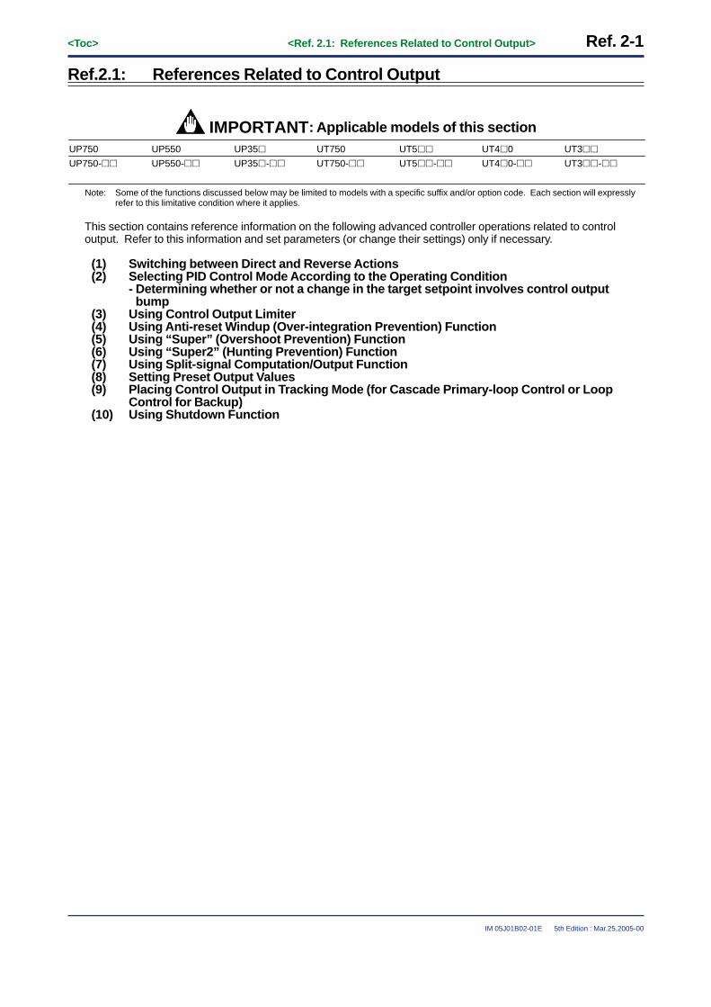
<Toc> <Ref. 2.1: References Related to Control Output> Ref. 2-1
IM 05J01B02-01E 5th Edition : Mar.25,2005-00
Ref.2.1: References Related to Control Output
IMPORTANT: Applicable models of this sectionUP750 UP550 UP35� UT750 UT5�� UT4�0 UT3��
UP750-�� UT750-��UP550-�� UP35�-�� UT5��-�� UT4�0-�� UT3��-��
Note: Some of the functions discussed below may be limited to models with a specific suffix and/or option code. Each section will expresslyrefer to this limitative condition where it applies.
This section contains reference information on the following advanced controller operations related to controloutput. Refer to this information and set parameters (or change their settings) only if necessary.
(1) Switching between Direct and Reverse Actions(2) Selecting PID Control Mode According to the Operating Condition
- Determining whether or not a change in the target setpoint involves control outputbump
(3) Using Control Output Limiter(4) Using Anti-reset Windup (Over-integration Prevention) Function(5) Using “Super” (Overshoot Prevention) Function(6) Using “Super2” (Hunting Prevention) Function(7) Using Split-signal Computation/Output Function(8) Setting Preset Output Values(9) Placing Control Output in Tracking Mode (for Cascade Primary-loop Control or Loop
Control for Backup)(10) Using Shutdown Function
Ref. 2-2<Toc> <Ref. 2.1: References Related to Control Output>
IM 05J01B02-01E 5th Edition : Mar.25,2005-00
<<Ref. 2.1: References Related to Control Output>>Ref.2.1(1) Switching between Direct and Reverse Actions
Switching between direct and reverse actions is possible with all models* in the UP and UT series of controllers.(*UP750, UP550, UP35�, UT750, UT5��, UT4�0 and UT3��)
The terms direct action and reverse action define the directions in which the control output changes to increase ordecrease its value according to whether the deviation of a measured value (PV) from the target setpoint (SP) ispositive or negative. The controller increases or decreases its control output value in the predetermined mode,either direct action or reverse action, in conjunction with the deviation of the current PV value from the SP value.Note that there are no direct/reverse action options for heating/cooling control.
You can switch between direct and reverse actions even when the controller is in operation. To switch, use theparameter appropriate for your controller model, as noted below.
• “n.DR” operating parameter for the UP750, UP550, UT750, UT5�� and UT4�0• DR operating parameter for the UP35� and UT3��
In the reverse action mode (factory-set default), the control output value decreases if the PV value is greater thanthe SP value. Inversely, it increases if the PV value is smaller than the SP value (see Fig. 2-1-1 below).
Condition
ON/OFF output status
Current output
Time proportional output
Direction of change in control output
PV>SP
OFF
Decreases.
The ON-state time decreases.
Reverse Action Direct Action
Reverse Action
SP value
Output value
(Increase)
(Decrease)
Minimum(PV value is smaller)
Maximum(PV value is greater)
4mA PV value
20mA
Direct Action
PV<SP
ON
Increases.
The ON-state time increases.
PV>SP
ON
Increases.
The ON-state time increases.
PV<SP
OFF
Decreases.
The ON-state time decreases.
↑
↓
Output value
(Increase)
(Decrease)
↑
↓
SP value
Minimum(PV value is smaller)
Maximum(PV value is greater)
4mA
20mA PV value
Fig. 2-1-1 Switching between Direct and Reverse Actions

<Toc> <Ref. 2.1: References Related to Control Output> Ref. 2-3
IM 05J01B02-01E 5th Edition : Mar.25,2005-00
● The following parameters are used.Change parameters as explained in the User's Manuals Initial Settings and Parameter Map.
• Operating parameters (PID-related Parameters) : n.DR
UP750UP550UT750Code(Note1)
UP35�UT3��
CodeSetting range Default D-register No.
• When UP750, UP550, UT750REVERSE: Reverse actionDIRECT: Direct action
• When UT5��, UT4�0 RVS: Reverse actionDIR : Direct action
• When UT3��/UP35�0 : Reverse action1 : Direct action
Reverse action• UP750, UP550, UT750 :
REVERSE• UT5��/UT4�0 : RVS• UT3��/UP35� : 0
UT5��UT4�0
Code(Note1)
n.DR
Description
Direct / reverse action switching(Note2)
(n.DR) (DR)n. • 257
(When UP35� or UT3��)(Note3)
Note1: “n” = 1 to 8. The number indicates the number of PID group.Note2: This parameter cannot be displayed when heating/cooling control mode.Note3: The D-register numbers are shown in the Table 2-1-1. ( except for UP35�, UT3��)
Table 2-1-1 1st=for loop-1 2nd=for loop-2 (UT4�0 has no loop-2)
n= 11st
313n.DR2nd
513
n=21st
3382nd
538
n=31st
3632nd
563
n=41st
3882nd
588 438 638 463 663 488 688
n=51st
4132nd
613
n=61st 2nd
n=71st 2nd
n=81st 2nd

Ref. 2-4<Toc> <Ref. 2.1: References Related to Control Output>
IM 05J01B02-01E 5th Edition : Mar.25,2005-00
<<Ref. 2.1: References Related to Control Output>>Ref.2.1(2) Selecting PID Control Mode According to the Operating Condition
- Determining whether or not a change in the target setpoint involves controloutput bump
With UP and UT series controllers, you can select between two types of PID control modes. These control modesare referred to as the standard PID control mode and fixed-point control mode.
For each of these PID control modes, select either the PV derivative type PID control method or deviation deriva-tive type PID control method to carry out control according to the operating condition (mode). You can also selectfrom the Yes/No options for a control output bump at the moment of change in the SP value. (See Table 2-1-2 or2-1-3 depending on your controller model.)
Note that there is a slight difference in this information between the UP750, UP550, UT750, UT5�� and UT4�0group of controllers and the UP35� and UT3�� group controllers.This section discusses the former group first and then the latter group. See either reference topic according toyour controller model.
[1] Control Mode Selection when the Model Is UP750, UP550, UT750, UT5�� or UT4�0
To select the PID control mode, use one of the setup parameters explained below.To set/change the parameter, see the Initial Settings or Parameters user’s manual of the model in question.
■ Setup Parameters for UP750, UP550 and UT750• Setup parameters (Control Action-related Parameters):MOD1, MOD2 and MOD
UP750UP550
Code
Description Setting Range
0: Standard PID control mode1: Fixed-point control mode
9270
Default D-register No.
UT750
Code
MOD1 MOD(Note1)
Loop-1 PID control mode
0: Standard PID control mode1: Fixed-point control mode
9670MOD2(Note2)
MOD(Note1)
Loop-2 PID control mode
Note1: For the UT750, the MOD setup parameter applies to both the loop-1 and loop-2 PID control modes. More specifically, the MOD setupparameter belonging to the LOOP2 setup parameter main menu is used for the loop-2 PID control mode of the UT750. In addition, thesetup parameter has the same name, MOD, as the one that belongs to the LOOP1 menu (though their D-register numbers differ, asshown in the table above).The MOD setup parameter for loop 2 is only shown when the UT mode is cascade control, dual-loop control, temperature/humiditycontrol or cascade control with two universal inputs.
Note2: The MOD2 setup parameter for the loop-2 PID control mode of the UP750 or UP550 is only shown when the UP mode is cascadecontrol, dual-loop control, temperature/humidity control or cascade control with two universal inputs.
■ Setup Parameters for UT5�� and UT4�0• Setup parameters (Control Action-related Parameters):MOD
Description Setting Range
0: Standard PID control mode1: Fixed-point control mode
9270
Default D-register No.
UT5��UT4�0
Code
PID control mode(MOD)
Note: For the UT5�� and UT4�0, there is no parameter for loop-2.

<Toc> <Ref. 2.1: References Related to Control Output> Ref. 2-5
IM 05J01B02-01E 5th Edition : Mar.25,2005-00
The relationship between the control mode and operating condition of the UP750, UP550, UT750, UT5�� andUT4�0 is as shown in Table 2-1-2 below.Refer to the information under “Control Method” and “Description of Control Action,” to set the type of PID controlmode appropriate for the operating condition (mode) you will use, using the setup parameter discussed earlier.
Table 2-1-2 Control Mode vs. Operating Condition Relationship for UP750, UP550, UT750, UT5�� and UT4�0
Type of PID Control Mode
Control Method Description of Control Action Operating Condition (Mode)
Standard PID control mode
Factory-set values
For the UP�50, the mode is defined by setting MODn = 0 (n = 1 or 2).
For the UT750, the mode is defined by setting MOD = 0.
PV derivative type PID control
Control output bump is allowed during change in SP value.
Deviation derivative type PID control
The PV derivative type PID control mode is adopted so that the controller can reach the new SP value without delay when the current SP value is changed. In this control mode, the controller immediately outputs the value of the proportional term P which is proportional to the deviation resulting from a change in the SP value. The controller thus attempts to reach the new SP value as soon as possible.
The deviation derivative type PID control mode is adopted in order to improve the follow-up capability of UP series program controllers for marginal variations in the SP value of a program pattern. By allowing the derivative term D to positively act upon variations resulting from a marginal change in the program pattern, the controller keeps track of the pattern without delay.
• For UT series (Note1) Local mode operation
• For UP series (Note2) Local mode (Note3), hold mode or soak mode operation
• For UT series Remote mode or cascade mode operation
• For UP series Program mode operation (except for hold or soak mode)
SP
SP
PV MV
PV MV
• For UT series (Note1) Local mode operation
• For UP series (Note2) Local mode (Note3), hold mode or soak mode operation
Fixed-point control mode
Factory-set valuesFor the UP�50, the mode is defined by setting as MODn = 1 (n = 1 or 2).
For the UT750, the mode is defined by setting as MOD = 1.
PV derivative type PID control
Control output bump is not allowed during change in SP value.
PV derivative type PID control
Control output bump is allowed during change in SP value.
Use this control method in order to protect the PV value from any disorder that may result when the control output (MV) reacts over-sensitively against a change in the SP value during continuous fixed-point control.If the PV derivative type PID control mode is used with the permitted control output bump, the MV value does not change suddenly during a change in the SP value. The controller uses the integral term I only and gradually eliminates the deviation that has occurred.
Use this control method when using the controller for the secondary loop of cascade control. In this method, the control output never reacts over-sensitively against a change in the primary-loop output. Rather, it delivers stable control output.
• For UT series Remote mode or cascade mode operation
• For UP series Program mode operation (except for hold or soak mode)SP
MV
PV
SP
PV MV
Note1: In the table above, the UT series refers to the UT750, UT5��, UT4�0 and UT3��.Note2: In the table above, the UP series refers to the UP750, UP550 and UP35�.Note3: The local mode of the UP series refers to the operating mode in which the SP value is kept constant.

Ref. 2-6<Toc> <Ref. 2.1: References Related to Control Output>
IM 05J01B02-01E 5th Edition : Mar.25,2005-00
[2] Control Mode Selection when the Model Is UP35�, UT35� or UT32�
To select the PID control mode, use one of the setup parameters explained below.To set/change the parameter, see the Initial Settings or Parameters user’s manual of the model in question.
• Setup parameters (Control Action-related Parameters):C.MD
Description Setting Range
0: Standard PID control mode1: Fixed-point control mode
9270
Default D-register No.
UP35�UT3��
Code
PID control mode(C.MD)
The relationship between the control mode and operating condition of the UP35�, UT35� and UT32� is asshown in Table 2-1-3 below.Refer to the information under “Control Method” and “Description of Control Action,” to set the type of PID controlmode appropriate for the operating condition (mode) you will use, using the setup parameter discussed earlier.
Table 2-1-3 Control Mode vs. Operating Condition Relationship for UP35�, UT35� and UT32� (1/2)
Type of PID Control Mode
Control Method Description of Control ActionOperating Condition (Mode)
PV derivative type PID control
Control output bump is allowed during change in SP value.
Deviation derivative type PID control
The PV derivative type PID control mode is adopted so that the controller can reach the new SP value without delay when the current SP value is changed. In this control mode, the controller immediately outputs the value of the proportional term P which is proportional to the deviation resulting from a change in the SP value. The controller thus attempts to reach the new SP value as soon as possible.
The deviation derivative type PID control mode is adopted in order to improve the follow-up capability of UP series program controllers for marginal variations in the SP value of a program pattern. By allowing the derivative term D to positively act upon variations resulting from a marginal change in the program pattern, the controller keeps track of the pattern without delay.
• For UT3�� When “SP number” isset to 1, 2, 3 or 4.
• For UP35� Hold mode or soak mode operation
• For UT3�� When “SP number” isset to 0. (When using communication function)
• For UP35� Program mode operation (except for hold or soak mode)
Standard PID control mode
Factory-set values
C.MD = 0
SP
SP
PV MV
PV MV

<Toc> <Ref. 2.1: References Related to Control Output> Ref. 2-7
IM 05J01B02-01E 5th Edition : Mar.25,2005-00
Table 2-1-3 Control Mode vs. Operating Condition Relationship for UP35�, UT35� and UT32� (2/2)
• For UT3�� When “SP number” isset to 1, 2, 3 or 4.
• For UP35� Hold mode or soak mode operation
Type of PID Control Mode
Control Method Description of Control ActionOperating Condition (Mode)
Fixed-point control mode
C.MD = 1
PV derivative type PID control
Control output bump is not allowed during change in SP value.
PV derivative type PID control
Control output bump is allowed during change in SP value.
Use this control method in order to protect the PV value from any disorder that may result when the control output (MV) reacts over-sensitively against a change in the SP value during continuous fixed-point control.If the PV derivative type PID control mode is used with the permitted control output bump, the MV value does not change suddenly during a change in the SP value. The controller uses the integral term I only and gradually eliminates the deviation that has occurred.
Use this control method when using the controller for the secondary loop of cascade control. In this method, the control output never reacts over-sensitively against a change in the primary-loop output. Rather, it delivers stable control output.
• For UT3�� When “SP number” isset to 0. (When using communication function)
• For UP35� Program mode operation (except for hold or soak mode)
SP
MV
PV
SP
PV MV

Ref. 2-8<Toc> <Ref. 2.1: References Related to Control Output>
IM 05J01B02-01E 5th Edition : Mar.25,2005-00
<<Ref.2.1: References Related to Control output>>Ref.2.1(3) Using Control Output Limiter
This function can be used with UP750, UP550, UT750, UT5��, UT4�0 and UT3��.For the function, the parameters “n.OH” and “n.OL” are used.These parameters limit the control output, regardless of the operation mode.UT750, UT5��, UT4�0, UP750 and UP550 can set up to eight sets of “n.OH” and “n.OL”. (n=1 to 8)
CAUTIONThe preset output value output when the controller operation stopped, will not be limited even when the“n.OH” and “n.OL” limits of output have been set.
-5.0 105.0 (%)
Variablerange
n.OHn.OL
Range of outputsignal variation
Original variable range
Note: Setting range : -5.0% � n.OL � n.OH � 105.0%
0
(%)
105.0
Sig
nal o
utpu
t fro
m th
e te
rmin
al Output high limit
Output low limit
Fig. 2-1-2
● The following parameters are used.Change parameters as explained in the User's Manuals Initial Settings and Parameter Map.
• Operating parameters (PID-related Parameters) : n.OH, n.OL
UP750UP550UT750Code
UP35�UT3��
CodeDescription Setting range
-5.0 to 105%(OL�OH), 0.0 to 100.0%(in heating/cooling control)
• 254(When UP35�, UT3��)
• See Table 2-1-4(except for UP35�, UT3��)
• 255(When UP35�, UT3��)
• See Table 2-1-4(except for UP35�, UT3��)
100.0%
0.0%100.0%(in heating/cooling control)
Default D-register No.
UT5��UT4�0
Code
n.OL
(Note1)
n.OH
(Note1)
Output high limitHeating-side output high limit (in heating/cooling control) (Note2)
Output low limitCooling-side output high limit (in heating/cooling control) (Note2)
-5.0 to 105%(OL�OH), 0.0 to 100.0%(in heating/cooling control)
(OH)
(OL)
(n.OH)
(n.OL)
n.
n.
n.
Note1: “n”=1 to 8, means the number of PID group.Note2: Not displayed in ON/OFF control mode.
Table 2-1-4 1st : for loop-1 2nd : for loop-2 (UT4�0 has no loop-2)
n=11st
309310
n.OHn.OL
2nd509510
n=21st
334335
2nd534535
n=31st
359360
2nd559560
n=41st
384385
2nd584585
434435
634635
459460
659660
484485
684685
n=51st
409410
2nd609610
n=61st 2nd
n=71st 2nd
n=81st 2nd

<Toc> <Ref. 2.1: References Related to Control Output> Ref. 2-9
IM 05J01B02-01E 5th Edition : Mar.25,2005-00
<<Ref.2.1: References Related to Control output>>Ref.2.1(4) Using Anti-reset Windup (Over-integration Prevention) Function
NoteThe parameter AR is not used to turn on and off the anti-reset windup function.
This function can be used with UP750, UP550, UP35�, UT750, UT5��, UT4�0 and UT3��.
• Parameter AR sets the point (by specifying a deviation ratio (%)) at which to restart the integral computationthat is suspended by the controller’s anti-reset windup function. (Integral computation restarts when thedeviation ratio has decreased to the AR value.)
• The deviation ratio (setting range of “AR”) is obtained by the following expression.
Deviation ratio(= Setpoint of AR)
� 100 (%)Proportional band (n.P)
| PV - n.SP |=
• The setting range for the deviation ratio set in parameter AR is 50.0 to 200.0%. However, when the parameteris set at AUTO, another setting option, the controller automatically determines the point at which to restart theintegral computation.
● The following parameters are used.Change parameters as explained in the User's Manuals Initial Settings and Parameter Map.
• Setup parameters (Control Action-related Parameters) : AR, etc.
UP750UP550UT750Code
UP35�UT3��
Code
Description Setting range
AUTO or 50.0 to 200.0%
928
968 : loop-2 (Note1)
AUTO
Default D-register No.
UT5��UT4�0
Code
AR1AR2
(Note1)
Anti-resetwind up (AR) (AR)
Note1: “AR2” are displayed only when the loop-2 is used (by UT/UP mode).

Ref. 2-10<Toc> <Ref. 2.1: References Related to Control Output>
IM 05J01B02-01E 5th Edition : Mar.25,2005-00
<<Ref. 2.1: References Related to Control Output>>Ref.2.1(5) Using “Super” (Overshoot Prevention) Function
The “Super” (overshoot prevention) function is available with the UP750, UP550, UP350, UT750, UT5��, UT4�0and UT3��. This function works when you set the “Super” code SC to 1. It does not work if you set the code toOFF. If the code is set to OFF, the controller operates in the regular PID control mode. (The code is set to OFFwhen the controller is shipped from the factory.)If you set the code to 2 or 3, the “Super2” (hunting prevention) function works. For more information on the“Super2” functions, see Ref. 2.1 (6).
CAUTIONThe SUPER function can only be used with the PID function. If both the integral time and derivative time areset to OFF, the SUPER function will not operate even when SC is set to 1.
The SUPER function operates under the condition that P, I, and D are set up. It is therefore more efficient to set theSUPER code (SC) to 1 after auto-tuning is carried out.
The SUPER function is an overshoot-suppressing function that uses fuzzy inference. This function is highlyeffective when used together with the auto-tuning function in the event of the following.
• Overshoots must be suppressed.• Rise-up time needs to be shortened.• Load varies often.• SP is changed frequently.
When the SUPER function is set on, the controller monitors deviation in order to detect the possibility of anovershoot. When the possibility of overshoot is detected, the controller changes the target setpoint to a tentativevalue as a secondary setpoint (auxiliary setpoint SSP) and continued control. Then, when the possibility of an overshoot no longer exists, the target setpoint is gradually reset to its original value.
SP
Start of fuzzy inferenceTime
Temperature
PV
Secondary SP
Super ON
Fig. 2-1-3
● The parameters used in this reference topic are as shown below.To set/change any of the parameters, see the Initial Settings or Parameter Map user’s manual of the model inquestion.
• Operating parameters (Operation-related Parameters):SC
UP750UP550UT750
Code
Description Setting Range
OFF, or 1, 2 or 3 (Note1)
Loop 1: 242Loop 2: 272 (Note3)
OFF (Note2)
Default D-register No.
UT5��UT4�0UP3��UT3��Code
SC On/off of “Super” function
(SC)
Note1: When selecting the “Super” function, set the SC code to 1. If you set the SC code to either 2 or 3, the “Super2” hunting-preventingfunction works. This means you cannot use both the “Super” and “Super2” functions at the same time.
Note2: The “Super” function is turned off when the controller is shipped from the factory.Note3: Loop 2 is supported only by models other than the UP35�, UT4�0 and UT3��.

<Toc> <Ref. 2.1: References Related to Control Output> Ref. 2-11
IM 05J01B02-01E 5th Edition : Mar.25,2005-00
<<Ref. 2.1: References Related to Control Output>>Ref.2.1(6) Using “Super2” (Hunting Prevention) Function
The “Super2” (hunting prevention) function is available with the UP750, UP550, UP350, UT750, UT5��, UT4�0and UT3��. This function works when you set the “Super” code SC to either 2 or 3. It does not work if you setthe code to OFF. If the code is set to OFF, the controller operates in the regular PID control mode. (The code isset to OFF when the controller is shipped from the factory.)If you set the code to 1, the “Super” (overshoot prevention) function works. For more information on the “Super”functions, see Ref. 2.1 (5).
CAUTION• Use “Super2” only for PID or PI control. The function does not work in any of the following control modes.
On-off control, P control (control using the proportional band term only), PD control (control using theproportional band and derivative terms only), and heating/cooling control.
• Do not use the “Super 2” function for the fast-response process such as flowrate or pressure control.
If you will use the “Super2” function for PID control, also use auto-tuning together with the function to maximize thefunction’s capability. After auto-tuning, set the “Super” code SC to either 2 or 3.
“Super2” is effective when used in the following cases.
The “Super2” function is designed to prevent hunting by means of a phase compensation block built in the PIDcomputation block (see Fig. 2-1-4 below).
PID computation block MV
Switch for turning on/off Super 2 functionPV
OFFON
SP
Phase compensation block
Fig. 2-1-4
“Super2” is effective when used in the following cases.
• There is a frequent change in the load.• The controller is exposed to a high degree of disturbance and takes time to settle to normal.• Even if the PID constants are correctly set, hunting remains when the SP value is changed.
The “Super2” hunting-preventing function has two modes, as shown in Table 2.1.5. You can select either of themby setting the SC parameter accordingly.
Table 2-1-5
Mode Feature Value of SC Parameter
Stability-oriented mode Superior in control stability against a change in the load or SP value. This mode supports a wider range of characteristic change, compared with the responsiveness-oriented mode.
This mode provides shorter PV tracking time/settling time for a change in the SP value.
2
3Responsiveness-oriented mode
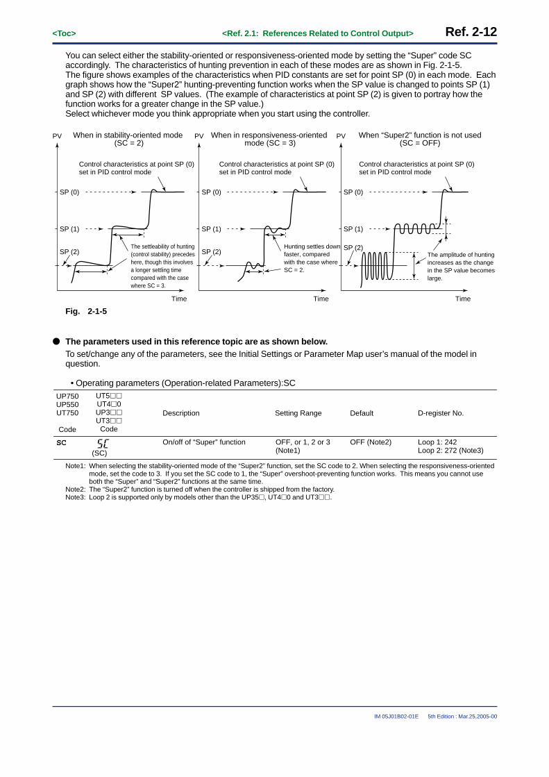
Ref. 2-12<Toc> <Ref. 2.1: References Related to Control Output>
IM 05J01B02-01E 5th Edition : Mar.25,2005-00
You can select either the stability-oriented or responsiveness-oriented mode by setting the “Super” code SCaccordingly. The characteristics of hunting prevention in each of these modes are as shown in Fig. 2-1-5.The figure shows examples of the characteristics when PID constants are set for point SP (0) in each mode. Eachgraph shows how the “Super2” hunting-preventing function works when the SP value is changed to points SP (1)and SP (2) with different SP values. (The example of characteristics at point SP (2) is given to portray how thefunction works for a greater change in the SP value.)Select whichever mode you think appropriate when you start using the controller.
SP (0)
Time
SP (1)
SP (2)The settleability of hunting (control stability) precedes here, though this involves a longer settling time compared with the case where SC = 3.
Control characteristics at point SP (0) set in PID control mode
PV When in stability-oriented mode (SC = 2)
SP (0)
Time
SP (1)
SP (2)Hunting settles down faster, compared with the case where SC = 2.
Control characteristics at point SP (0) set in PID control mode
PV When in responsiveness-oriented mode (SC = 3)
SP (0)
Time
SP (1)
SP (2)The amplitude of hunting increases as the change in the SP value becomes large.
Control characteristics at point SP (0) set in PID control mode
PV When “Super2” function is not used(SC = OFF)
Fig. 2-1-5
● The parameters used in this reference topic are as shown below.To set/change any of the parameters, see the Initial Settings or Parameter Map user’s manual of the model inquestion.
• Operating parameters (Operation-related Parameters):SC
UP750UP550UT750
Code
Description Setting Range
OFF, or 1, 2 or 3 (Note1)
Loop 1: 242Loop 2: 272 (Note3)
OFF (Note2)
Default D-register No.
UT5��UT4�0UP3��UT3��
Code
SC On/off of “Super” function
(SC)
Note1: When selecting the stability-oriented mode of the “Super2” function, set the SC code to 2. When selecting the responsiveness-orientedmode, set the code to 3. If you set the SC code to 1, the “Super” overshoot-preventing function works. This means you cannot useboth the “Super” and “Super2” functions at the same time.
Note2: The “Super2” function is turned off when the controller is shipped from the factory.Note3: Loop 2 is supported only by models other than the UP35�, UT4�0 and UT3��.

<Toc> <Ref. 2.1: References Related to Control Output> Ref. 2-13
IM 05J01B02-01E 5th Edition : Mar.25,2005-00
<<Ref.2.1: References Related to Control output>>Ref.2.1(7) Using Split-signal Computation / Output Function
This function can be used with UP750, UP550, UT750, UT550, UT551 and UT520.There are two modes ( "V-mode Output" and "Parallel-mode Output" ) of the split-signal computation.
[1] When “V-mode Output”
0 5025 75 100%
%mA
Output value before split computation
Out
put v
alue
afte
r co
mpu
tatio
n Analog output-1 100% segmental point (A1H)
Analog output-1 0% segmental
point (A1L)
Analog output-3 100% segmentalpoint (A3H)
Analog output-3 0% segmental point (A3L)
Analog output-3
25
0
50
75
10020
4
12
8
16
Analog output-1
[Example of the V-mode output] [Outline]
Analog output 1
Analog output 3
Analog output 2
Control output terminalsare used.
Control outputterminals for cooling side
are used.
Retransmission output terminals
are used.
Fig. 2-1-6
The following explains an example of letting “Analog OUTPUT-1 (terminals [16] and [17])” and “Analog OUTPUT-3(terminals [14] and [15])” present the V-mode characteristics of split computations.
[1] Set the Control Output Type (OT1) parameter to “2”.This sets the control output to “current output.”
[2] Set the Retransmission Output (RT1) parameter to “3”.This sets the retransmission output to “control output retransmission.”
[3] Set the Analog Output-1 100% Segmental Point(A1H) parameter to “100%”.[4] Set the Analog Output-1 0% Segmental Point(A1L) parameter to “25%”.[5] Set the Analog Output-3 100% Segmental Point(A3H) parameter to “0%”.[6] Set the Analog Output-3 0% Segmental Point(A3L) parameter to “75%”.
The figure above shows an example where both analog outputs-1 and 3 are set to the current signal of 4 to 20 mADC. The type of output signal can be determined separately for each of the analog outputs listed above, using thefollowing three parameters.Analog output-1: Analog output-1 type (AO1)Analog output-2: Analog output-2 type (AO2)Analog output-3: Analog output-3 type (AO3)

Ref. 2-14<Toc> <Ref. 2.1: References Related to Control Output>
IM 05J01B02-01E 5th Edition : Mar.25,2005-00
[2] When “Parallel-mode Output”
[Example of the parallel-mode output] [Outline]
Analog output 1
Analog output 3
Analog output 2
Control output terminalsare used.
Control outputterminals for cooling side
are used.
Retransmission output terminals
are used.
0 5025 75 100
25
50
75
100
%
%0
mA
20 0
10
15
5
Output value before split computation
Out
put v
alue
afte
r co
mpu
tatio
n Analog output-1 100% segmental point (A1H)
Analog output-3 100% segmental
point (A3H)
Analog output-3 0% segmental
point (A3L)
Analog output-1 0% segmental point (A1L)
Analog output-1
Analog output-3
Fig. 2-1-7
The following explains an example of letting “Analog OUTPUT-1 (terminals [16] and [17])” and “Analog OUTPUT-3(terminals [14] and [15])” present the Parallel-mode characteristics of split computations.
[1] Set the Control Output Type (OT1) parameter to “2”.This sets the control output to “current output.”
[2] Set the Retransmission Output (RT1) parameter to “3”.This sets the retransmission output to “control output retransmission.”
[3] Set the Analog Output-1 100% Segmental Point(A1H) parameter to “100%”.[4] Set the Analog Output-1 0% Segmental Point(A1L) parameter to “25%”.[5] Set the Analog Output-3 100% Segmental Point(A3H) parameter to “75%”.[6] Set the Analog Output-3 0% Segmental Point(A3L) parameter to “0%”.
The figure above shows an example where both analog outputs-1 and 3 are set to the current signal of 20 to 0 mADC. The type of output signal can be determined separately for each of the analog outputs listed above, using thefollowing three parameters.Analog output-1: Analog output-1 type (AO1)Analog output-2: Analog output-2 type (AO2)Analog output-3: Analog output-3 type (AO3)
Table 2-1-6
Parameter Function Split computation output terminal Output signal type setting parameter
A1H Analog output-1 100%segmental point Control output terminal
(Heating side terminal in Heating/cooling control)AO1 (Note1)
A1L Analog output-1 0%segmental point
A2H Analog output-2 100%segmental point Cooling side output terminal
Available for the dual-loop type of UT750/UP750 and heating/cooling control of UT55�/UP550.
AO2 (Note1)A2L Analog output-2 0%
segmental point
A3H Analog output-3 100%segmental point
Retransmission-1 output terminal AO3 (Note1)A3L Analog output-3 0%
segmental point
Note1: You can select the output signal type from Table 2-1-7. To select them, use the parameter “AO1”, “AO2” or “AO3”.

<Toc> <Ref. 2.1: References Related to Control Output> Ref. 2-15
IM 05J01B02-01E 5th Edition : Mar.25,2005-00
Table 2-1-7
Setting range of AO1, AO2 or AO3 Output signal type
0 (Default)123
4 to 20mA0 to 20mA20 to 4mA20 to 0mA
● The following parameters are used.Change parameters as explained in the User's Manuals Initial Settings and Parameter Map.
Table 2-1-8
• Setup parameters (Output-related Parameters): AO1 to AO3 and A1H to A3L
UP750UP550UT750Code
Description Setting range
0 : 4 to 20mA1 : 0 to 20mA2 : 20 to 4mA3 : 20 to 0mA
-5.0 to 105.0 (%)For UT551 -100.0 to 200.0 (%)
12440
Default D-register No.
UT5��
Code
AO1 Analog output-1 type
(AO1)
12450AO2 Analog output-2 type
(AO2)
12460AO3 Analog output-3 type
(AO3)
1268100 (%)A1H Analog output-1 100%segmental point(A1H)
12690 (%)A1L Analog output-1 0%segmental point(A1L)
1270100 (%)A2H Analog output-2 100%tumaround point(A2H)
12710 (%)A2L Analog output-2 0%segmental point(A2L)
1272100 (%)A3H Analog output-3 100%segmental point(A3H)
12730 (%)A3L Analog output-3 0%segmental point(A3L)

Ref. 2-16<Toc> <Ref. 2.1: References Related to Control Output>
IM 05J01B02-01E 5th Edition : Mar.25,2005-00
<<Ref.2.1: References Related to Control output>>Ref.2.1(8) Setting Preset Output Values
This function can be used with UP750, UP550, UP35�, UT750, UT5��, UT4�0 and UT3��.However, the preset output function differs depending on the controller model.This section explains the function for each of the following models. Refer to the paragraph that is applicable toyour model.
[1] When the model is UP750, UP550, UT750, UT5�� or UT4�0.[2] When the model is UP35�, UT35� or UT32�.
CAUTION• The default value of the preset output values is set to 0.0% of control output.
Change the setting value if necessary.• The setting range of the preset output values is -5.0% to 105.0% of control output.
However, the preset output value will not be limited even when the “n.OH” and “n.OL” limits of output havebeen set.
[1] When the model is UP750,UP550,UT750,UT5�� or UT4�0
In the following situations, the controller outputs the preset output value.• An input burnout has occurred during the AUTO mode or CAS mode operation.• An abnormality in an analog/digital conversion circuit has occurred during the AUTO mode or CAS mode
operation.• The status of the controller changed from the operating mode to the stop mode.
(With UP750 or UP550, the status changed from the operating mode to the reset mode.)
● The following parameters are used.Change parameters as explained in the User's Manuals Initial Settings and Parameter Map.
• Operating parameters ( PID-related Parameters): n.PO and n.Oc
UP750UP550
Code
Description Setting range
-5.0 to 105.0 (%)Heating-side: 5.0 to 105.0(%)
See Table2-1-90.0
Default D-register No.
UT750UT5��UT4�0Code
n.PO Preset output (Note1)
See Table2-1-90.0n.Oc Cooling-side preset output (Note2)
Cooling-side: -5.0 to 105.0(%)
n.(n.PO)
n.(n.Oc)
Note1: Heating-side preset output in heating/cooling control mode.Note2: The parameter can be displayed in heating/cooling control mode.
Table 2-1-9 D-register No. list
n=11st
320321
n.POn.Oc
2nd520521
n=21st
345346
2nd545546
n=31st
370371
2nd570571
n=41st
395396
2nd595596
445446
645646
470471
670671
495496
695696
n=51st
420421
2nd620621
n=61st 2nd
n=71st 2nd
n=81st 2nd

<Toc> <Ref. 2.1: References Related to Control Output> Ref. 2-17
IM 05J01B02-01E 5th Edition : Mar.25,2005-00
The UT551 can output the manual preset output value when the opration mode is changed from Auto to Manual.The control output value is changed to the manual preset output value with a bump at operation mode changing.
With bump
With bump
Bumpless
Auto
Parameter M.MD=1(Manual preset output value)
Manual
Parameter M.MD=0(Output value bumpless)
Run→Stop
Auto→Manual
Output Value
Manual preset output value (n.PO)
Output Value
Manual preset output value (MPO)
Fig. 2-1-8 Action when the operation mode is change from Auto to Manual
• Operating parameters: M.MD and MPO
0: Automatic operation output at switching (bumpless)1: Manual preset outout value (MPO)
-5.0 to 105.0 (%)However, output is limited to the output high limit (OH) and low limit (OL) manual operation.In heating/cooling control, internal computation result before splitted into heating-side and cooling-side signals.
See Table2-1-100
See Table2-1-100.0Manual preset outout value (MPO)
Manual preset outout selection(M.MD)
(MPO)
Description Setting range Default D-register No.UT551
Code
Table 2-1-10 D-register No. list for the parameters of manual preset output value
1st980981
M.MDMPO
2nd982983

Ref. 2-18<Toc> <Ref. 2.1: References Related to Control Output>
IM 05J01B02-01E 5th Edition : Mar.25,2005-00
[2] When the model is UP35�,UT35� or UT32�
In the following situations, the controller outputs the preset output value.• An input burnout has occurred during the AUTO mode operation.• An abnormality in an analog/digital conversion circuit has occurred during the AUTO mode operation.• With UP35�, the status changed from the operating mode to the reset mode.
● The following parameters are used.Change parameters as explained in the User's Manuals Initial Settings and Parameter Map.
• Setup parameters (Control Function-related Parameters): PO and POc (Note2)
Description Setting range
0.0 to 105.0 (%)
-5.0 to 105.0 (%) 9240.0
Default D-register No.
UP35�UT3��
Code
Preset output (Note1)
9250.0Cooling-side preset out (Note2)
(PO)
(POc)
Note1: Heating-side preset output in heating/cooling control mode.The setting range in heating/cooling control mode is 0.0 to 105.0% of control output
Note2: The parameter can be displayed in heating/cooling control mode. UP35� does not have the parameter.
<<Ref. -2.1: References Related to Control Output>>-Ref.2.1(9) Placing Control Output in Tracking Mode (for Cascade Primary-loop Control
or Loop Control for Backup)
Placing the control output in tracking mode is possible with the UP750, UP550, UT750, UT550, UT551 andUT520.
As noted in the heading above, this feature works only when the controller is used for cascade primary-loopcontrol or loop control for backup (though the UP750 and UP550 do not support loop control for backup).
Output tracking is a function with which switching is carried out between an external tracking input signal and thecontrol output signal of the controller by means of a contact input or communication. The output tracking functionworks only when the controller is in either of the two control modes discussed above. Fig. 2-1-8 briefly illustrateshow this function works.
Manual output
PID
Control output
Tracking input PV input Input for switching to tracking mode
Fig. 2-1-8 Output Tracking Function

<Toc> <Ref. 2.1: References Related to Control Output> Ref. 2-19
IM 05J01B02-01E 5th Edition : Mar.25,2005-00
<<Ref. 2.1: References Related to Control Output>>Ref.2.1(10) Using Shutdown Function
Using the shutdown function is possible with the UP750, UP550, UT750, UT550, UT551 and UT520.The shutdown function is designed to fully close a control valve (forcibly zeroes the output) by sending a signallevel beyond the limit of the dead band of the positioner of the valve. This function is enabled by setting the outputlimiter’s lower limit (n.OL [n = 1 to 8] parameter) to the option “SD” when the controller is set to a 4 to 20 mAcurrent output signal and in manual mode.
• When in automatic mode operationThe output limiter’s lower limit is set at -5.0% and is not lowered to 0.0 mA.
• When in manual mode operationThe control output delivers a shutdown signal (approximately 0.0 mA) when decreased to the setpoint SD withthe key (the SD symbol is displayed as the output value).
Control output
20.0mA
–5.0%
100.0%Output reading
3.2mA4.0mA
0.0mA
Fig. 2-1-9 Relationship between Output and Shutdown Levels in Continuous PID Control Mode

Ref. 2-20<Toc> <Ref. 2.2: References Related to Retransmission Output>
IM 05J01B02-01E 5th Edition : Mar.25,2005-00
Ref.2.2: References Related to Retransmission Output
IMPORTANT: Applicable models of this sectionUP750
UP750-��
UT750
UT750-��
UP550
UP550-��
UP35�
UP35�-��
UT5��
UT55�-��UT520-��
UT4�0
UT450-��UT420-��
UT3��
UT35�-��UT32�-��
Note: The functions discussed in this section apply to all the models of UT and UP series.However, some of the functions are unavailable with certain models.Such models, if any, will be clearly noted in each of the following items from (1) to (3).
These sections provide references related to Retransmission Output, listed below.Only read the following descriptions if necessary and carry out the required operation.
(1) Changing the type of retransmission output signal(2) Retransmitting program pattern 2 (for UP750/UP550 only)(3) Using the loop power supply function

<Toc> <Ref. 2.2: References Related to Retransmission Output> Ref. 2-21
IM 05J01B02-01E 5th Edition : Mar.25,2005-00
<<Ref. 2.2: Reference Related to Retransmission Output>>Ref.2.2(1) Changing the type of retransmission output signal
The type of retransmission output signal can be changed with all the GREEN Series UT or UPControllers.We show the changing way with UP750,UP550,UT750, UT550, UT551 and UT520 below.The way with UP35�, UT450, UT420, UT35� and UT32� are shown in the next page.
[1] When the Model Is UP750, UP550,UT750 or UT5��
The type of retransmission output signal is changed using the following setup parameter.Change the parameter settings as explained in the Initial Settings or Parameters user’s manual that comes with your controller.
• Setup parameters (Retransmission Output Parameters) : RET1, RET2 (Note1)
UP750UP550UT750Code
Description Setting range
OFF or 1 to 7 (Note2) 10131
Default D-register No.
UT5��
Code
RET1 Retransmission output -1 type selection
OFF or 1 to 7 (Note2) 1016OFFRET2 Retransmission output -2 type selection
(RT1)
(RT2)
Note1: The parameter RT1 and RT2 are parameters with UT550, UT551 and UT520.Note2: See the below Table 2-2-1 for the meaning of the setting values .
Table 2-2-1 Parameter Settings and Types of Retransmission Output
Parameter Setting Type of Retransmission Output
OFF Turns the function off (no retransmission output is used).
1 PV1 (Measured value 1) (TIP1)
2 SP1 (Setpoint 1) (TIP1)
3 OUT1 (Control output 1) (TIP1)
However, the following conditions apply if the parameter is set to “3”. • In position proportional control, a valve opening (0 to 100%) is output.• In heating/cooling control, the output value before allocation to the heating and
cooling sides is output. (0 to 50%: Cooling-side output, 0 to 50%: Heating-side output)
4 Loop power supply
5 PV2 (Measured value 2)
6 SP2 (Setpoint 2)
7 OUT2 (Control output 2)
(Note 1)
(Note 2) (TIP2)
(Note 2) (TIP2)
(Note 2) (TIP2)
8 TSP1 (Target setpoint 1)
9 HOUT1 (Heating-side control output in the control other than cascade control)
10 COUT1 (Cooling-side control output in the control other than cascade control)
11 OUT1 (Position proportional control output in the control other than cascade control) (Internally computed output)
(TIP3)
(TIP3)
(TIP3)
(TIP3, TIP4)
12 TSP2 (Target setpoint 2)
13 HOUT2 (Heating-side control output in cascade control)
14 COUT2 (Cooling-side control output in cascade control)
15 OUT2 (Position proportional control output in cascade control) (internally computed output)
(TIP3)
(TIP3)
(TIP3)
(TIP3, TIP4)
16 AI1 (Analog input 1) (Setup parameter RL1 to RH1)
17 AI3 (Analog input 3) (Setup parameter RL3 to RH3)
(TIP3)
(TIP3)
Note1: For more information on the loop power supply, see “(3) Using the Loop Power Supply Function.”Note2: PV2, SP2 and OUT2 are available for controller modes (UP/UT modes) that use a secondary loop. These types of retransmission
output cannot be used for single-loop control. This feature is not supported with the UP35�, UT4�0 and UT3�0.

Ref. 2-22<Toc> <Ref. 2.2: References Related to Retransmission Output>
IM 05J01B02-01E 5th Edition : Mar.25,2005-00
TIP1: The retransmission range can be represented with the PV input range scaled with RTH1* (Max. value) and RTL1* (Min. value).TIP2: The retransmission range can be represented with the PV input range scaled with RTH2* (Max. value) and RTL2* (Min. value).
*: When UT5��, TH1, TH2, TL1 and TL2 are used.TIP3: The setpoints “8” to “17 ” can be set for UT551 only. However, the UT551 with embedded Ethernet dose not have heating/cooling control.TIP4: When opening or closing a valve by key operation in manual mode opration, the transmission output becomes -5.0 %.
[2] When the Model Is UP35�, UT4�0 or UT3��
The type of retransmission output signal is changed using the following setup parameter.Change the parameter settings as explained in the Initial Settings or Parameters user’s manual that comes with your controller.
• Setup parameters (Retransmission Output Parameters) : RETUP35�UT4�0UT3��Code
Description Setting range
OFF or 1 to 4 (Note1) 10131
Default D-register No.
Retransmission output -1 type(RET)
Note1: See the below Table 2-2-2 for the meaning of the setting values .
Table 2-2-2 Parameter Settings and Types of Retransmission Output
Parameter Setting Type of Retransmission Output
OFF Turns the function off (no retransmission output is used).
1 PV1 (Measured value 1) *TIP
2 SP1 (Target setpoint 1) *TIP
3 OUT1 (Control output 1) *TIP
However, the following conditions apply if the parameter is set to “3”. • In position proportional control, a valve opening (0 to 100%) is output.• In heating/cooling control, the output value before allocation to the heating and
cooling sides is output. (0 to 50%: Cooling-side output, 0 to 50%: Heating-side output)
4 Loop power supply (Note 1)
Note1: For more information on the loop power supply, see “(3) Using the Loop Power Supply Function.”*TIP: The retransmission range can be represented with the PV input range scaled with RTH (Max. value) and RTL (Min. value).

<Toc> <Ref. 2.2: References Related to Retransmission Output> Ref. 2-23
IM 05J01B02-01E 5th Edition : Mar.25,2005-00
<<Ref. 2.2: References Related to Retransmission Output>>Ref.2.2(2) Retransmitting Program Pattern 2 (for UP750/UP550 only)
CAUTIONThe UP750 and UP550 can retransmit program pattern 2 as explained below, though this is not possible withthe following controller modes (UP modes) of these controllers.• UP750: Cascade control, dual-loop control, temperature and humidity control, cascade control with univer-
sal input• UP550: Cascade control
The UP750 and UP550 can retransmit program pattern 2 that is set for running on loop 2. For this reason, theycan also serve as program generators. Both controllers can retransmit program pattern 2 at the same time whenthey are running their own program patterns.
TIP
The “PT2.G” parameter designed for this function is called the “Program Pattern 2 Retransmission” param-eter, because it retransmits a program pattern used for loop 2.
To retransmit program pattern 2, the “RET1” and “RET2” setup parameters discussed in the previous section andthe “PT2.G” parameter related to target setpoints are used. The terminals used for retransmission differ depend-ing on which of the “RET1” or “RET2” parameters you select; therefore, you should also be careful with terminalwiring. Furthermore, exercise care not to use these terminals for control output.
Follow the steps below to configure these parameters:
[1] Set the “PT2.G” parameter to “ON”.[2] Set either the “RET1” or “RET2” parameter to “6”.
As discussed earlier, the setting value “6” is used to select the target setpoint-2 (SP2) retransmissionoutput.
This completes parameter setting.
Program pattern retransmission will begin at the same time when the controller goes into program operation.
● The following parameters are used.Change parameters as explained in the User’s Manuals Initial Settings and Parameter Map.
• Setup parameters (Target Setpoint related Parameters) : PT2.G
UP750UP550
Code
Description Setting range
OFF or ON 906OFF
Default D-register No.
PT2.G Program pattern -2 retransmission

Ref. 2-24<Toc> <Ref. 2.2: References Related to Retransmission Output>
IM 05J01B02-01E 5th Edition : Mar.25,2005-00
<<Ref. 2.2: References Related to Retransmission Output>>Ref.2.2(3) Using the Loop Power Supply Function
CAUTIONThe loop power supply is available in two voltage levels.(1) The 14.5 to 18.0V DC (21 mA DC) voltage level is the standard loop power supply for all controller
models. This standard feature becomes available when you specify the type of retransmission output.See the explanation given below.
(2) The 21.6 to 28.0V DC (30 mA max.) voltage level is added to your controller as an option if specified (bythe option code) at the time of ordering. This optional feature is assigned to specific terminals prior todelivery. Therefore, you can use the feature directly without having to select a type of retransmissionoutput as explained below.
[1]Using the Standard Loop Power Supply
UP750UP550UT750Code
UP35�UP4�0UT3�� Description Setting range
4
UT5��
Code
RET1 Retransmission output 1 type selection
4(Note)
RET2 Retransmission output 2 type selection
(RT1) (RET)
(RT2) (Note)
As discussed in “Ref. 2.2 (1) Changing the Type of Retransmission Output” earlier in this section, set the relevant parameter (see the table below) to “4” in order to use the standard loop power supply.
• Setup parameters (Retransmission Output Parameters)
Note: “Retransmission output 2 type selection” is not supported with the UP35h, UT4h0 and UT5hh.
The terminals used for retransmission differ depending on which of the “RET1” or “RET2” parameters you select;therefore, you should also be careful with terminal wiring. Furthermore, exercise care not to use these terminalsfor control output at the same time.

<Toc> <Ref. 2.2: References Related to Retransmission Output> Ref. 2-25
IM 05J01B02-01E 5th Edition : Mar.25,2005-00
[2]About the Loop Power Supply FunctionThe loop power supply function supplies DC power to instruments, such as a two-wire transmitter. The loop powersupply block is isolated from the controller’s internal circuitry. In addition, the block is equipped with a current-limiting circuit. Therefore, accidental short-circuits that may occur in the field do not adversely affect the rest of thecontroller’s internal circuitry.Note that the loop power supply function cannot be used for digital communication where the supply voltage issuperposed on the signal line.
As explained earlier, there are two types of loop power supply: the standard and optional power supplies. Useeither of them according to your application needs.
Specifications of Loop Power Supply
Standard supply 14.5 to 18.0V DC (21 mA DC)
Optional supply 21.6 to 28.0V DC (30 mA DC max.)
Examples of loop power supply connection are given below.
12
White
Input terminal (1 to 5 V)
Controller
Shielded wire
GND terminal
Use a terminal block, if necessary.
FP100
+
-
+ -
Green Red Black
13
14
Power supply
15
10
Fig. 2-2-1 Example of Connection with FP100 Cable
Two-wire transmitter
50�0.2-1Vdc
Controller
Fig. 2-2-2 Example of Connection to Two-wireTransmitter

Blank Page

<Toc> <Ref. 3.1: References Related to Contact Input> Ref. 3-1
IM 05J01B02-01E 5th Edition : Mar.25,2005-00
Ref.3.1: References Related to Contact Input
IMPORTANT: Applicable models of this sectionUP750
UP750-��
UT750
UT750-��
UP550
UP550-��
UP35�
UP35�-��
UT5��
UT55�-��UT520-��
UT4�0
UT450-��UT420-��
UT3��
UT35�-��UT32�-��
Note: The functions discussed in this section apply to all the models of UT and UP series.However, some of the functions are unavailable with certain models.Such models, if any, will be clearly noted in each of the following items from (1) to (7).
CAUTIONThe contact input functions of a UT/UP series controller are pre-assigned to their respective input terminalswhen the controller is shipped from the factory. The function assignments in each of the UT/UP modes aredefined in terms of the most frequently used. Check the controller model you will use and the factory-setterminal assignments for each controller mode of the model. Changes should only be made if you require anyof the functions listed below or need to change any of the terminal numbers.If you change any of the contact input terminal assignments, check that the new assignment agrees with thecurrent wiring. If necessary, rewire the terminals.
This section contains reference information on the following aspects of contact input functions. Refer to thisinformation and change parameter settings only if necessary.
This section explains the function for each of the following models. Refer to the paragraph that ia applicable toyour model.
When the UT series controllers
(1) Changing contact input functions for the UT35�/UT32�(2) Changing contact input functions for the UT450/UT420(3) Changing contact input functions for the UT55�/UT520
Note : The function discussed in the following reference topic are not included in your controller model, and these are not described in thismanual.
(4) Changing contact input functions for the UT750(4-1) Changing contact input terminal assignments of the UT750(4-2) Using contact I/O expansion module with the UT750(4-3) Using Interrupt-message functions with the UT750(4-4) Using Interrupt-operating display functions with the UT750
When the UP series controllers
(5) Changing contact input functions for the UP35�(6) Changing contact input functions for the UP550(7) Changing contact input functions for the UP750
(7-1) Changing contact input terminal assignments of the UP750(7-2) Using contact I/O expansion module with the UP750(7-3) Using Interrupt-message functions with the UP750(7-4) Using Interrupt-operating display functions with the UP750

Ref. 3-2<Toc> <Ref. 3.1: References Related to Contact Input>
IM 05J01B02-01E 5th Edition : Mar.25,2005-00
When the UT series controllers
<<Ref. 3.1: References Related to Contact Input>>Ref.3.1(1) Changing contact input functions for the UT35�/UT32�
Each UT35� and UT32� comes with three contact input terminals that can be used, for example, to change theoperation mode. When the controller is shipped from the factory, the terminals are set to the functions “switchingbetween target setpoints 1 and 2” and “switching between the auto and manual modes.”
The terminal numbers are 18, 19 and 20 (common terminals). Terminal 18 is assigned as DI1 (for contact input 1)and terminal 19 as DI2 (for contact input 2). (See the terminal wiring diagrams in the Installation user’s manual.)
< UT35� Terminal Arrangement >
When switching target SP 1 to 4:
DI1
DI2
1.SP2.SP3.SP4.SP
OFF
OFFOFF
ON ON
ON
OFF
ON
Correspondence between parameters DIS and external contact input functions
When DIS=4
DI1
DI2
COMCommon
When DIS=3
2.SP when DI1=ON 1.SP when DI1=OFF
STOP when DI2=ON RUN when DI2=OFF
Common
When DIS=2
Hides the LOCK parameter when DI1=ON.Shows the LOCK parameter when DI1=OFF.
Common
When DIS=1 (Factory-shipped setting)
2.SP when DI1=ON 1.SP when DI1=OFF
AUTO when DI2=ONMAN when DI2=OFF
Common
When DIS=OFF
No function
No function
Common
Contact
No function
19
18
20
UT
1
2
3
4
5
6
7
8
9
10
41
42
43
44
45
46
47
48
49
50
31
32
33
34
35
36
37
38
39
40
21
22
23
24
25
26
27
28
29
30
11
12
13
14
15
16
17
18
19
20
DI1(No.19)
Terminal
* DIS is a setup parameter. Changing DIS setpoint allows you to change the function of external contact input.
Tip : The terminal numbers of UT32� are same as of UT35�.
DI2(No.18)
COM.(No.20)
Fig. 3-1-1 UT35�/UT32� Contact Input Terminals
The UT35� and UT32� are designed so that the functions assigned to their contact input terminals can bechanged using the “DIS” setup parameter. If necessary, reassign functions by referring to the table in the Fig. 3-1-1.

<Toc> <Ref. 3.1: References Related to Contact Input> Ref. 3-3
IM 05J01B02-01E 5th Edition : Mar.25,2005-00
● The following parameters are used.Change parameters as explained in the User’s Manuals Initial Settings and Parameter Map.
• Setup parameters (I/O-related Parameters): DIS
Description Setting range
OFF: Turns contact input off.
1: • Assigns the functions of switching between 2.SP and 1.SP to DI1. (Note1)
• Assigns the function of switching between auto and manual modes to DI2. (Note1)
2: • Assigns the function of showing and hiding the “Keylock (LOCK)” setup parameter setting display to DI1. (Note2)
• Nothing is assigned to DI2. 3: • Assigns the function of selecting the target
setpoint number by turning on or off the DI1 and DI2 contact inputs. (Note3)
4: • Assigns the function of switching between 2.SP and 1.SP to DI1. (Note4)
• Assigns the function of switching between the STOP and RUN statuses to DI2. (Note4)
9321
Default D-register No.
UT35�UT32�
Display
DI function selection(DIS)
Note1: When switching between setpoints 2.SP and 1.SP is assigned, 2.SP is selected when the contact is ON and 1.SP is selected when thecontact is OFF. In operation mode switching, the auto mode is selected when the contact is ON and the manual mode is selected whenthe contact is OFF.
Note2: The “Keylock (LOCK)” setup parameter setting display is hidden when the DI1 contact is ON and is shown when the contact is OFF.This function of hiding the keylock parameter using external input is an extra safeguard against erroneous operations.
Note3: The ON and OFF states of the DI1 and DI2 contact inputs can be programmed as shown below to define four choices of targetsetpoints.
1.SP
DI1
OFF
DI2
OFF
2.SP ON OFF
3.SP OFF ON
4.SP ON ON
Note4: When switching between the target setpoints 2.SP and 1.SP is assigned, 2.SP is selected when the contact is ON and 1.SP is selectedwhen the contact is OFF. In the case of switching between the STOP and RUN statuses, the STOP status is selected when the contactis ON and the RUN status is selected when the contact is OFF.

Ref. 3-4<Toc> <Ref. 3.1: References Related to Contact Input>
IM 05J01B02-01E 5th Edition : Mar.25,2005-00
Part of the parameter map for the UT35�/UT32� is shown below. Refer to it when changing parameter values inorder to access the desired parameter setting display.
CAUTIONIf you change any contact input terminal assignment, check that the new assignment agrees with the currentwiring. If necessary, rewire the terminals.
Operating display
Setup parameter map
Note1: Pressing the key on the [OP.PA] display changes to the “ ” operating parameter setting display.
Note2: If you have set a password, “[FUNC]” is not displayed unless the correct password is entered.
Note3: The displays and can be switched with or key.
(Note1)
(Note2)
SET/ENTSET/ENT
SET/ENTSET/ENT
SET/ENTSET/ENT
SET/ENTSET/ENT
SET/ENTSET/ENT
(Note3)
SET/ENTkey 3 sec. or more
1. Call up the “I/O” display.(Refer to the Note 1 to 3 above)
2. Press the key to display the parameter “DIS” setting display.
SET/ENT
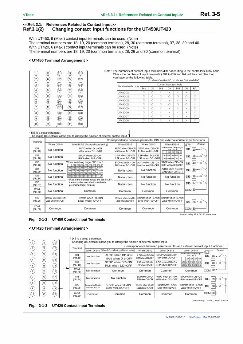
<Toc> <Ref. 3.1: References Related to Contact Input> Ref. 3-5
IM 05J01B02-01E 5th Edition : Mar.25,2005-00
<<Ref. 3.1: References Related to Contact Input>>Ref.3.1(2) Changing contact input functions for the UT450/UT420
With UT450, 9 (Max.) contact input terminals can be used. (Note)The terminal numbers are 18, 19, 20 (common terminal), 28, 30 (common terminal), 37, 38, 39 and 40.With UT420, 6 (Max.) contact input terminals can be used. (Note)The terminal numbers are 18, 19, 20 (common terminal), 28, 29 and 30 (common terminal).
< UT450 Terminal Arrangement >
1
2
3
4
5
6
7
8
9
10
41
42
43
44
45
46
47
48
49
50
31
32
33
34
35
36
37
38
39
40
21
22
23
24
25
26
27
28
29
30
11
12
13
14
15
16
17
18
19
20
* DIS is a setup parameter. Changing DIS setpoint allows you to change the function of external contact input.
DI1(No.19)
Terminal
DI2(No.18)
DI3(No.40)
DI4(No.39)
DI5(No.38)
DI6(No.37)
COM.(No.20)
R/L(No.28)
COM.(No.30)
Note : The numbers of contact Input terminals differ according to the controllers suffix code.Check the numbers of input terminals ( DI1 to DI6 and R/L) of the controller that you have by the following table.
Contact input terminalsModel and suffix codes
DI1 DI2 DI3 DI4 DI5 DI6 R/L
UT450-�1
UT450-�0
�
�
�: shows “available” , �: shows “not available”
UT450-�2 �
UT450-�3 �
UT450-�4 �
�
UT420-07
UT420-00
�
UT420-08 �
�
�
�
�
� �
� �
�
�
�
�
� �
� �
�
�
�
�
� �
� �
�
�
�
�
� �
� �
�
�
�
�
� �
� �
�
�
�
�
� �
� �
19
18
Correspondence between parameter DIS and external contact input functions
40
39
38
37
20
28
30
When DIS=4
DI1
DI2
DI3
DI4
DI5
DI6
COM
COM
R/L
STOP when DI3=ON RUN when DI3=OFF
AUTO when DI4=ONMAN when DI4=OFF
No function
Common
Remote when R/L=ONLocal when R/L=OFF
Common
When DIS=3
STOP when DI1=ONRUN when DI1=OFF
2.SP when DI2=ON 1.SP when DI2=OFF
AUTO when DI3=ON MAN when DI3=OFF
No function
No function
Common
Remote when R/L=ONLocal when R/L=OFF
Common
When DIS=2
AUTO when DI1=ONMAN when DI1=OFF
2.SP when DI2=ON 1.SP when DI2=OFF
STOP when DI3=ON RUN when DI3=OFF
No function
No function
Common
Remote when R/L=ONLocal when R/L=OFF
Common
When DIS=1 (Factory-shipped setting)
AUTO when DI1=ONMAN when DI1=OFF
STOP when DI2=ON RUN when DI2=OFF
* If all of the contact inputs are set to OFF, the controller uses the immediately preceding target setpoint.
DI3DI4
1.SP2.SP3.SP4.SPON
ONOFFOFF
ONON OFF
OFF
5.SP6.SP7.SP8.SPON
ONOFFOFF
ONON OFF
OFFDI5DI6
OFFOFF
OFFOFF
OFFOFF
ONOFF
ONOFF
ONOFF
ONOFF
OFFON
Common
Remote when R/L=ONLocal when R/L=OFF
Common
When DIS=0
No function
No function
No function
No function
No function
No function
Remote when R/L=ONLocal when R/L=OFF
Common
When switching target SP 1 to 4:
DI1
DI2
1.SP2.SP3.SP4.SP
OFF
OFFOFF
ON ON
ON
OFF
ON
When switching target SP 1 to 8:
Contact
Contact rating: 12 V DC, 10 mA or more
UT
No functionNo functionNo functionNo function
Fig. 3-1-2 UT450 Contact Input Terminals
< UT420 Terminal Arrangement >
DI1(No.19)
Terminal
DI2(No.18)
COM.(No.20)
DI3(No.24)
R/L(No.28)
COM.(No.30)
1
2
3
4
5
6
7
8
9
10
21
22
23
24
25
26
27
28
29
30
11
12
13
14
15
16
17
18
19
20
* DIS is a setup parameter. Changing DIS setpoint allows you to change the function of external contact input.
19
18
20
29
28
30
DI1
DI2
COM
DI3
COM
R/L
Common
Common
Common
Common
Common
Common
Common
Common
No function
No function
No function
No function
Common
DI1
DI2
1.SP2.SP3.SP 4.SP
OFF
OFFOFF
ON ON
ON
OFF
ON
Contact
Correspondence between parameter DIS and external contact input functions
When DIS=4 When DIS=3When DIS=2When DIS=1 (Factory-shipped setting) When DIS=0When switching target
SP 1 to 4:AUTO when DI1=ONMAN when DI1=OFFSTOP when DI2=ON RUN when DI2=OFF
Contact rating: 12 V DC, 10 mA or more
AUTO when DI1=ONMAN when DI1=OFF
2.SP when DI2=ON 1.SP when DI2=OFF
STOP when DI1=ONRUN when DI1=OFF
2.SP when DI2=ON 1.SP when DI2=OFF
Remote when R/L=ONLocal when R/L=OFF
Remote when R/L=ONLocal when R/L=OFF
Remote when R/L=ONLocal when R/L=OFF
Remote when R/L=ONLocal when R/L=OFF
Remote when R/L=ONLocal when R/L=OFF
UT
No function STOP when DI3=ON RUN when DI3=OFF
STOP when DI3=ON RUN when DI3=OFF
AUTO when DI3=ON MAN when DI3=OFF
Fig. 3-1-3 UT420 Contact Input Terminals

Ref. 3-6<Toc> <Ref. 3.1: References Related to Contact Input>
IM 05J01B02-01E 5th Edition : Mar.25,2005-00
The UT450’s DI numbers (DI No.) and the corresponded terminal numbers are listed in the Table 3-1-1. (Thefactory-set function of each terminal is listed in the table.)The Table 3-1-3 shows the UT420’s. (The factory-set function of each terminal is listed in the table.)
Table 3-1-1 (When the UT450)
Terminal No.
19
DI No.
DI1
The factory-set function
Assigns the function of switching between auto and manual modes.
18 DI2 Assigns the function of switching between STOP and RUN statuses.
40 DI3
Assigns the function of selecting the target setpoint number (1.SP to 8.SP). (Note1)
39 DI4
38 DI5
37 DI6
20 Common terminal
28 R/LAssigns the function of switching between remote and local modes.
30 Common terminal
Note1: The ON and OFF status of the DI3, DI4, DI5 and DI6 contact inputs can be programmed as shown in the Table 3-1-2 to define eight (8)choices of target setpoints.
Table 3-1-2
1.SP
DI3
ON
DI4
OFF
DI5
OFF
DI6
OFF
2.SP OFF ON OFF OFF
3.SP ON ON OFF OFF
4.SP OFF OFF ON OFF
5.SP ON OFF ON OFF
6.SP OFF ON ON OFF
7.SP ON ON ON OFF
8.SP OFF OFF OFF ON
Table 3-1-3 (When the UT420)
Terminal No.
19
DI No.
DI1
The factory-set function
Assigns the function of switching between auto and manual modes.
18 DI2 Assigns the function of switching between STOP and RUN statuses.
20 Common terminal ( for DI1 and DI2 )
29 DI3 No function
28 R/L Assigns the function of switching between remote and local modes.
30 Common terminal ( for DI3 and R/L )

<Toc> <Ref. 3.1: References Related to Contact Input> Ref. 3-7
IM 05J01B02-01E 5th Edition : Mar.25,2005-00
The UT450 and UT420 are designed so that the functions assigned to their contact input terminals can be changeusing the “DIS” setup parameter.If necessary, reassign functions by referring to the “DIS” setup parameter table on page Ref. 3-8.
CAUTIONIf you change any of the contact input terminal assignments, check that the new assignment agree with thecurrent wiring. If necessary, rewire the terminals.
Operating display
UT450/UT420 Parameter map
Setup parameter menu
3 sec. or moreSET
SET
SET
/
RLRHUNIIN
DP
DIS
BSLSLSH
RJC
RSLRSHRSP
DPC
CTcCTOT
SP ALM CTL RET LOCK CSET I/O R485 VALV INIT
/
“DIS”
1. Call up the “I/O” display.2. Press the key to display
the parameter “DIS” setting display.
SET/ENT
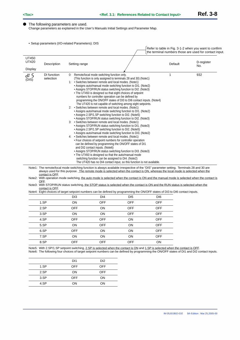
Ref. 3-8<Toc> <Ref. 3.1: References Related to Contact Input>
IM 05J01B02-01E 5th Edition : Mar.25,2005-00
● The following parameters are used.Change parameters as explained in the User’s Manuals Initial Settings and Parameter Map.
• Setup parameters (I/O-related Parameters): DIS
Refer to table in Fig. 3-1-2 when you want to confirm the terminal numbers those are used for contact input.
Setting range
0: Remote/local mode switching function only. (This function is only assigned to terminals 28 and 30) (Note1)
1: • Switches between remote and local modes. (Note1)• Assigns auto/manual mode switching function to DI1. (Note2)• Assigns STOP/RUN status switching function to DI2. (Note3)• The UT450 is designed so that eight choices of setpoint numbers for controller operation can be defined by programming the ON/OFF states of DI3 to DI6 contact inputs. (Note4) The UT420 is not capable of switching among eight setpoints.
2: • Switches between remote and local modes. (Note1)• Assigns auto/manual mode switching function to DI1. (Note2)• Assigns 2.SP/1.SP switching function to DI2. (Note5)• Assigns STOP/RUN status switching function to DI2. (Note3)
3: • Switches between remote and local modes. (Note1)• Assigns STOP/RUN status switching function to DI1. (Note3)• Assigns 2.SP/1.SP switching function to DI2. (Note5)• Assigns auto/manual mode switching function to DI3. (Note2)
4: • Switches between remote and local modes. (Note1)• Four choices of setpoint numbers for controller operation can be defined by programming the ON/OFF states of DI1 and DI2 contact inputs. (Note6)• Assigns STOP/RUN status switching function to DI3. (Note3)• The UT450 is designed so that the auto/manual mode switching function can be assigned to DI4. (Note2) The UT420 has no DI4 contact input, so this function is not available.
1
Default
932
D-register No.Description
DI function selection
UT450UT420
Display
(DIS)
Note1: The remote/local mode switching function is always available irrespective of the “DIS” parameter setting. Terminals 28 and 30 arealways used for this purpose. The remote mode is selected when the contact is ON, whereas the local mode is selected when thecontact is OFF.
Note2: With operation mode switching, the auto mode is selected when the contact is ON and the manual mode is selected when the contact isOFF.
Note3: With STOP/RUN status switching, the STOP status is selected when the contact is ON and the RUN status is selected when thecontact is OFF.
Note4: Eight choices of target setpoint numbers can be defined by programming the ON/OFF states of DI3 to DI6 contact inputs.
1.SP
DI3
ON
DI4
OFF
DI5
OFF
DI6
OFF
2.SP OFF ON OFF OFF
3.SP ON ON OFF OFF
4.SP OFF OFF ON OFF
5.SP ON OFF ON OFF
6.SP OFF ON ON OFF
7.SP ON ON ON OFF
8.SP OFF OFF OFF ON
Note5: With 2.SP/1.SP setpoint switching, 2.SP is selected when the contact is ON and 1.SP is selected when the contact is OFF.Note6: The following four choices of target setpoint numbers can be defined by programming the ON/OFF states of DI1 and DI2 contact inputs.
1.SP
DI1
OFF
DI2
OFF
2.SP ON OFF
3.SP OFF ON
4.SP ON ON

<Toc> <Ref. 3.1: References Related to Contact Input> Ref. 3-9
IM 05J01B02-01E 5th Edition : Mar.25,2005-00
<<Ref. 3.1: References Related to Contact Input>>Ref.3.1(3) Changing contact input functions for the UT550/UT551/UT520
With UT55�, 10 (Max.) contact input terminals can be used. (Note)The terminal numbers are 18, 19, 20 (common terminal), 28, 30 (commmon terminal), 36, 37, 38, 39 and 40.With UT520, 6 (Max.) contact input terminals can be used. (Note)The terminal numbers are 18, 19, 20 (common terminal), 28, 29 and 30 (commmon terminal).
< UT550/UT551 Terminal Arrangement >
1
2
3
4
5
6
7
8
9
10
41
42
43
44
45
46
47
48
49
50
31
32
33
34
35
36
37
38
39
40
21
22
23
24
25
26
27
28
29
30
11
12
13
14
15
16
17
18
19
20
* The functionality of a contact input can be varied by changing the setting of the contact input registration parameter.
Note: The numbers of contact Input terminals differ according to the controllers suffix code.Check the numbers of input terminals (DI1 to DI8) of the controller that you have by the following table.
Contact input terminalsModel and suffix codes DI1 DI2 DI3 DI4 DI5 DI6 DI8
UT55�-�1, UT551-�B
UT55�-�0, UT551-�A
�
�
UT55�-�2, UT551-�C �
UT55�-�3, UT551-�D �
UT55�-�4 �
�
UT520-07
UT520-00
�
UT520-08 �
�
�
�
�
� �
� �
�
�
�
�
� �
� �
�
�
�
�
� �
� �
�
�
�
�
� �
� �
�
�
�
�
� �
� �
�
�
�
�
� �
� �
DI7
�
�
�
�
�
�
�
�
�: shows “available” , �: shows “not available”
19
18
External contact inputs
40
39
38
37
20
28
30
DI1
DI2
DI3
DI4
DI5
DI6
COM
COM
DI8
AUTO when DI1=ONMAN when DI1=OFF
STOP when DI2=ON RUN when DI2=OFF
DI3
DI4
1.SP2.SP3.SP4.SP
ONONOFFOFF
ONON OFF
OFF
5.SP6.SP7.SP8.SP
ONONOFFOFF
ONON OFF
OFF
DI5
DI6
OFF
OFF
OFF
OFF
OFF
OFF
ON
OFF
ON
OFF
ON
OFF
ON
OFF
OFF
ON
Common
Remote when DI8=ON Local when DI8=OFF
Common
When switching among target setpoints 1 to 8:
19
18
40
39
38
37
20
28
30
DI1
DI2
DI3
DI4
DI5
DI6
COM
COM
DI8
+5V
+5V
+5V
+5V
+5V
+5V
36DI7 36DI7
+5V
+5V
Contact Transistor contact
Contact rating: 12 V DC, 10 mA or more
No function
UT
* If all of the contact inputs are set to OFF, the controller uses the immediately preceding target setpoint.
Fig. 3-1-4 UT5�� Contact Input Terminals
The UT550/UT551’s DI numbers (DI No.) and the corresponded terminal numbers are listed in the Table 3-1-4.(The factory-set function of each terminal is listed in the table. )The Table 3-1-6 shows the UT520’s . (The factory-set function of each terminal is listed in the table. )
Table 3-1-4 (When the UT550/UT551, Single-loop control mode : UT mode 1)
Terminal No.
19
DI No.
DI1
The factory-set function
Assigns the function of switching between auto and manual modes.
18 DI2 Assigns the function of switching between STOP and RUN statuses.
40 DI3
Assigns the function of selecting the target setpoint number (1.SP to 8.SP). (Note1)
no function
39 DI4
38 DI5
37 DI6
20 Common terminal (for DI1 to DI7)
36 DI7
28 DI8Assigns the function of switching between remote and local modes.
30 Common terminal (for DI8)
( “I relay” no. +5000)
(5161)
(5162)
(5163)
(5164)
(5165)
(5166)
(5167)
(5168)
Note1: The ON and OFF status of the DI3, DI4, DI5 and DI6 contact inputs can be programmed as shown in the Table 3-1-5 to define eight (8)choices of target setpoints.

Ref. 3-10<Toc> <Ref. 3.1: References Related to Contact Input>
IM 05J01B02-01E 5th Edition : Mar.25,2005-00
Table 3-1-5
1.SP
DI3
ON
DI4
OFF
DI5
OFF
DI6
OFF
2.SP OFF ON OFF OFF
3.SP ON ON OFF OFF
4.SP OFF OFF ON OFF
5.SP ON OFF ON OFF
6.SP OFF ON ON OFF
7.SP ON ON ON OFF
8.SP OFF OFF OFF ON
Table 3-1-6 (When the UT520, Single-loop control mode : UT mode 1)
Terminal No.
19
DI No.
DI1
The factory-set function
Assigns the function of switching between auto and manual modes.
18 DI2 Assigns the function of switching between STOP and RUN statuses.
21 Common terminal ( for DI1 and DI2 )
29 DI3 No function
28 DI8 Assigns the function of switching between remote and local modes.
30 Common terminal ( for DI3 and DI8 )
( “I relay” no. +5000)
(5161)
(5162)
(5163)
(5168)
The UT550, UT551 and UT520 are designed so that functions assigned to their contact input terminals can bechanged.
Select the desired contact input terminal with which a function predefined for each setup parameter (contact inputregistration parameter) is executed. To do this, register the “I Relay” number corresponding to the terminal’s DInumber with the setup parameter whose function you want to use. See the following parameter flowchart.
If necessary, reassign functions by referring to the “DIS” setup parameter table.
CAUTIONIf you change any of the contact input terminal assignments, check that the new assignment agree with thecurrent wiring. If necessary, rewire the terminals.
Main menu
Sub menu
LOOP2LOOP1 CMLP
OK
Parameter Map
Password
(When the UT550 or UT520)
CONF UTMD
DISP
C.S4C.S3C.S2C.S1
C.S5
CSEL DO DI C.PYS
DO4DO3DO2DO1
DO5
DO7DO6
A/M
SETSETSET SET
P2BP2AP1BP1A
SET +
CASS/RR/L
SP.3
AUT
SP.1SP.0MAN
SP.2
For example, when you want to use the DI2(terminal number 18) for the function of Auto and Manual mode switching, call up the parameter “A/M” setting display and set the value to 5162.(The 5162 means “I relay” number of DI2 plus 5000.)• Refer to the Table 3-1-4 or the Table 3-1-6.

<Toc> <Ref. 3.1: References Related to Contact Input> Ref. 3-11
IM 05J01B02-01E 5th Edition : Mar.25,2005-00
● The following parameters are used.Change parameters as explained in the User’s Manuals Initial Settings and Parameter Map.
• Setup parameters (Contact Input Registration Parameters): A/M, R/L, S/R, CAS, AUT, MAN, SP.0, etc.
UT55�UT520
Code
Description Setting range Default (“I relay” number plus 5000.)
D-register No.
11295161 ( DI1)Auto/Manual switching (Note2)<Status switching>
11315168 (DI8)Remote/Local switching (Note3)<Status switching>
11335162 (DI2)Run/Stop switching (Note4)<Status switching>
11340( not specified)Switch to Cascade mode (only when incascade control) (Note5)<Rising edge switching>
11350( not specified)Switch to Auto mode (Note5)<Rising edge switching>
11360( not specified)Switch to Manual mode (Note5)<Rising edge switching>
11375163(DI3)Bit-0 of SP number setting (Note6)<Status switching>
11385164(DI4)Bit-1 of SP number setting (Note6)<Status switching>
11395165(DI5)Bit-2 of SP number setting (Note6)<Status switching>
11405166(DI6)Bit-3 of SP number setting (Note6)<Status switching>
The setting range equals the range of “I Relay” numbers (each number plus 5000) that correspond to the DI numbers of the contact input terminals you want to use. (Note1)
Refer to the Note 1 below for the relationship between the DI numbers and the “I Relay” numbers.
(A/M)
(R/L)
(S/R)
(CAS)
(AUT)
(MAN)
(SP.0)
(SP.1)
(SP.2)
(SP.3)
11740( not specified)Bit 0 of PID number seting<Status switching>
11750( not specified)Bit 1 of PID number seting<Status switching>
11760( not specified)Bit 2 of PID number seting<Status switching>
11770( not specified)
For UT551 only
Bit 3 of PID number seting<Status switching>
11780( not specified)Remote switching<Rising dege switching>
11800( not specified)Local switching<Rising dege switching>
(PN.0)
(PN.1)
(PN.2)
(PN.3)
(REM)
(LCL)
Note: For Remote/Local switching or Auto/Manual switching, do not use the status switching and the rising edge switching at the same time.
Note:PID number selection by external contact input is available only when the setup parameter ZON=3.

Ref. 3-12<Toc> <Ref. 3.1: References Related to Contact Input>
IM 05J01B02-01E 5th Edition : Mar.25,2005-00
Note1: The “I Relay” numbers used here are 161 to 168. DI numbers for contact input terminals are specified by these “I Relay” numbers eachof which is incremented by 5000. For more information on “I Relay” numbers, see Ref. 8.1(4).The relationship between the factory-set DI numbers and input terminal assignments may differ depending on the UT mode of yourcontroller. Always refer to the terminal wiring diagrams in the Installation user’s manual to verify the factory-set terminal assignments ofeach UT mode.The range of “I Relay” numbers (each number plus 5000) equals the setting range.
DI1: 5161DI2: 5162DI3: 5163DI4: 5164DI5: 5165DI6: 5166DI7: 5167DI8: 5168
Register an “I Relay” number (with an increment of 5000) with the parameter (e.g., A/M) of a function you want to use, as in theexample shown in the table where default numbers are registered. This specifies the terminal that will execute the function.
Note2: With operation mode switching, the auto mode is selected when the contact is ON and the manual mode is selected when the contact isOFF.
Note3: With control mode switching, the remote mode is selected when the contact is ON and the local mode is selected when the contact isOFF.
Note4: With STOP/RUN status switching, the STOP status is selected when the contact is ON and the RUN status is selected when thecontact is OFF.
Note 5: With cascade control, use separate contact input terminals to set the cascade, auto and manual modes. Each mode is executed whenthe state of the contact input changes from OFF to ON. It does not matter what the contact’s state (ON/OFF) was prior to the change.The UT551 can switch mode between auto and manual in the control modes other than cascage control.
Note 6: Parameters SP.0 to SP.3 correspond to bits 0 to 3 with which a selection is made from eight choices of target setpoints (see the tablebelow). When the controller is shipped from the factory, contact input DI3 (terminal number 40) is set to SP.0. Likewise, DI4 is set toSP.1, DI5 to SP.2 and DI6 to SP.3, as shown below.
Target setpoints
1.SP
<DI3>SP.0 (bit 0)
ON
<DI4>SP.1 (bit 1)
OFF
<DI5>SP.2 (bit 2)
OFF
<DI6>SP.3 (bit 3)
Target setpoints Pn.0 (bit 0) Pn.1 (bit 1) Pn.2 (bit 2) Pn.3 (bit 3)
OFF
2.SP OFF ON OFF OFF
3.SP ON ON OFF OFF
4.SP OFF OFF ON OFF
5.SP ON OFF ON OFF
6.SP OFF ON ON OFF
7.SP ON ON ON OFF
8.SP OFF OFF OFF ON
1.PID ON OFF OFF OFF
2.PID OFF ON OFF OFF
3.PID ON ON OFF OFF
4.PID OFF OFF ON OFF
5.PID ON OFF ON OFF
6.PID OFF ON ON OFF
7.PID ON ON ON OFF
8.PID OFF OFF OFF ON
CAUTIONFor Remote/Local switching or Auto/Manual switching, do not use the status swiching and the rising edgeswitching at the same time.

<Toc> <Ref. 3.1: References Related to Contact Input> Ref. 3-13
IM 05J01B02-01E 5th Edition : Mar.25,2005-00
� The Example of Auto/Manual Switching by External Contact Input (Rising Edge Switching)
The following example shows the switching from automatic operation to manual operation by external contactinput (rising edge switching).Rising edge switching to automatic operation:
Set “5161” (DI1) to the contact input registration parameter AUT.Rising edge switching to manual operation:
Set “5162” (DI2) to the contact input registration parameter MAN.The actions of the controller and key operation in this case are shown below.
<Rising edge switching>
DI1: AUTON
OFF
<Rising edge switching>
DI2: MAN
Operation mode of controller
Key operation
ON
OFF
Manual Manual Manual
Can be changed
Auto Auto
Fig. 3-1-5 The example of Auto/Manual switching by external contact input

Ref. 3-14<Toc> <Ref. 3.1: References Related to Contact Input>
IM 05J01B02-01E 5th Edition : Mar.25,2005-00
<<Ref. 3.1: References Related to Contact Input>>Ref.3.1(4) Changing contact input functions for the UT750
(4-1): Changing contact input terminal assignments of the UT750
With UT750, 8 (Max.) contact input terminals can be used. (Note)The terminal numbers are 18, 19, 20 (common terminal), 36, 37, 38, 39 and 40.
If these do not suffice your needs, using I/O expansion modules increases the number of available contact inputsto a maximum of 23. See (4-2): Using the I/O expansion module for the UT750
< UT750 Terminal Arrangement >
1
2
3
4
5
6
7
8
9
10
41
42
43
44
45
46
47
48
49
50
31
32
33
34
35
36
37
38
39
40
21
22
23
24
25
26
27
28
29
30
11
12
13
14
15
16
17
18
19
20
19
18
External contact inputs
40
39
38
37
20
DI1
DI2
DI3
DI4
DI5
DI6
COMCommon
19
18
40
39
38
37
20
DI1
DI2
DI3
DI4
DI5
DI6
COM
+5V
+5V
+5V
+5V
+5V
+5V
36DI7 36DI7
+5V
Transistor contact
* The functionality of a contact input can be varied by changing the setting of the contact input registration parameter.
Contact rating: 12 V DC, 10 mA or more
Remote when DI7=ON Local when DI7=OFF
STOP when DI6=ON RUN when DI6=OFF
AUTO when DI5=ON MAN when DI5=OFF
UT
DI3
DI4
1.SP2.SP3.SP4.SP
ONONOFFOFF
ONON OFF
OFF
5.SP6.SP7.SP8.SP
ONONOFFOFF
ONON OFF
OFF
DI5
DI6
OFF
OFF
OFF
OFF
OFF
OFF
ON
OFF
ON
OFF
ON
OFF
ON
OFF
OFF
ON
When switching among target setpoints 1 to 8:
* If all of the contact inputs are set to OFF, the controller uses the immediately preceding target setpoint.
Contact
Fig. 3-1-5 UT750 Contact Input Terminals
The UT750’s DI numbers (DI No.) and the corresponded terminal numbers are listed in the Table 3-1-7. (Thefactory-set function of each terminal is listed in the table.)
Table 3-1-7 (When the UT750, Single-loop control mode: UT mode 1)
Terminal No.
19
DI No.
DI1
The factory-set function
Assigns the function of switching between auto and manual modes. (Note2)
18 DI2
Assigns the function of switching between STOP and RUN statuses. (Note3)
40 DI3Assigns the function of selecting the target setpoint number (1.SP to 8.SP). (Note1)
39 DI4
38 DI5
37 DI6
20 Common terminal (for DI1 to DI7)
36 DI7 Assigns the function of switching between remote and local modes. (Note4)
( “I relay” no. +5000)
(5161)
(5162)
(5163)
(5164)
(5165)
(5166)
(5167)
Note1: The relationship between the ON/OFF status of each DI contact input and the setpoint numbers is given in Table 3-1-8.Note2: In a dual-loop control configuration, the loop-1 auto/manual mode switching function is assigned to DI5 when the controller is shipped
from the factory.Note3: In a dual-loop control configuration, the loop-2 auto/manual mode switching function is assigned to DI6 when the controller is shipped
from the factory.Note4: In a dual-loop control configuration, the STOP/RUN status switching function common to both loops is assigned to DI7 when the
controller is shipped from the factory.

<Toc> <Ref. 3.1: References Related to Contact Input> Ref. 3-15
IM 05J01B02-01E 5th Edition : Mar.25,2005-00
Table 3-1-8
1.SP
DI1
ON
DI2
OFF
DI3
OFF
DI4
OFF
2.SP OFF ON OFF OFF
3.SP ON ON OFF OFF
4.SP OFF OFF ON OFF
5.SP ON OFF ON OFF
6.SP OFF ON ON OFF
7.SP ON ON ON OFF
8.SP OFF OFF OFF ON
The UT750 is designed so that functions assigned to its contact input terminals can be changed. In addition,functions can be assigned to the terminals of an optional I/O expansion module.Select the desired contact input terminal with which a function predefined for each setup parameter (contact inputregistration parameter) is executed. To do this, register the “I Relay” number corresponding to the terminal’s DInumber with the setup parameter whose you want to see. Use the following parameter map to reassign terminalfunctions as necessary.
CAUTIONIf you change any of the contact input terminal assignments, check that the new assignment agrees with thecurrent wiring. If necessary, rewire the terminals.
LOOP2LOOP1 CMLP
OK
Setup Parameters Map Example of UT750
CONF UTMD
DISP
C.S4C.S3C.S2C.S1
C.S5
CSEL DO DI C.PYS
DO4DO3DO2DO1
DO5
DO7DO6
R154R153R152R151
R155
R157R156
R253R252R251R158
R254
R256R255
R258R257
A/M1
SETSETSET SET
PY2BPY2APY1BPY1A
SET
CASS/RR/L2
A/M2R/L1
DISP
SP.3
AUTO
SP.1SP.0MAN
SP.2
MG4
DP1
MG2MG1DP2
MG3
Main menu
Sub menu
Password
For example, when you want to use the DI2 (terminal number 18) for the function of Auto and Manual mode switching of the primary loop, call up the parameter “A/M1” setting display and set the value to 5162.(The 5162 means “I relay” number of DI2 plus 5000.)• Refer to the Table 3-1-7Note: The parameter “A/M1” is factory-set to
the DI5 as shown in the table below.
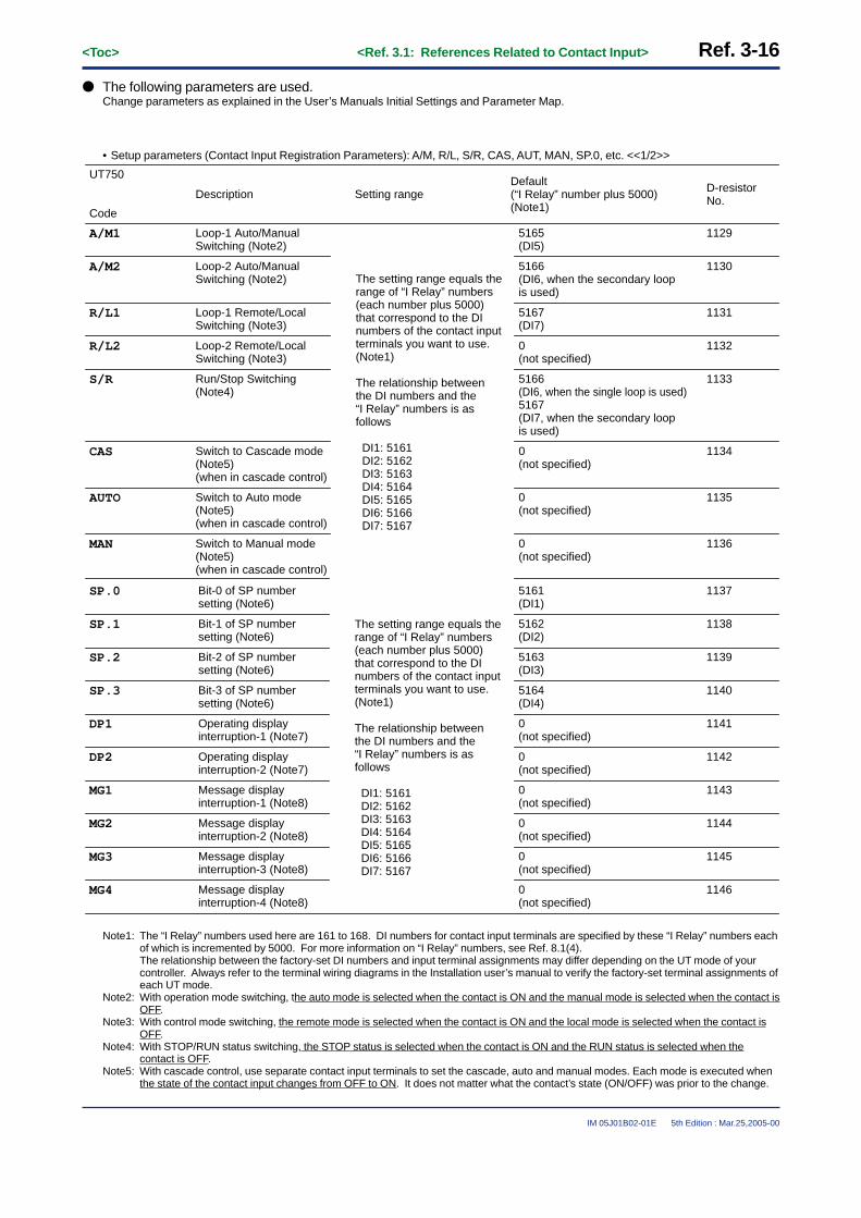
Ref. 3-16<Toc> <Ref. 3.1: References Related to Contact Input>
IM 05J01B02-01E 5th Edition : Mar.25,2005-00
● The following parameters are used.Change parameters as explained in the User’s Manuals Initial Settings and Parameter Map.
• Setup parameters (Contact Input Registration Parameters): A/M, R/L, S/R, CAS, AUT, MAN, SP.0, etc. <<1/2>>
UT750
Code
Description Setting range
11295165(DI5)
Default(“I Relay” number plus 5000)(Note1)
D-resistor No.
A/M1 Loop-1 Auto/ManualSwitching (Note2)
11305166(DI6, when the secondary loop is used)
A/M2 Loop-2 Auto/ManualSwitching (Note2)
11315167(DI7)
R/L1 Loop-1 Remote/LocalSwitching (Note3)
11320(not specified)
R/L2 Loop-2 Remote/LocalSwitching (Note3)
11335166(DI6, when the single loop is used)5167(DI7, when the secondary loop is used)
S/R Run/Stop Switching (Note4)
11340(not specified)
CAS Switch to Cascade mode(Note5)(when in cascade control)
11350(not specified)
AUTO Switch to Auto mode(Note5)(when in cascade control)
11360(not specified)
MAN Switch to Manual mode(Note5)(when in cascade control)
The setting range equals the range of “I Relay” numbers(each number plus 5000)that correspond to the DInumbers of the contact inputterminals you want to use.(Note1)
The relationship betweenthe DI numbers and the “I Relay” numbers is as follows
DI1: 5161 DI2: 5162 DI3: 5163 DI4: 5164 DI5: 5165 DI6: 5166 DI7: 5167
11375161(DI1)
SP.0 Bit-0 of SP number setting (Note6)
11385162(DI2)
SP.1 Bit-1 of SP number setting (Note6)
11395163(DI3)
SP.2 Bit-2 of SP number setting (Note6)
11405164(DI4)
SP.3 Bit-3 of SP number setting (Note6)
11410(not specified)
DP1 Operating display interruption-1 (Note7)
11420(not specified)
DP2 Operating display interruption-2 (Note7)
11430(not specified)
MG1 Message display interruption-1 (Note8)
11440(not specified)
MG2 Message display interruption-2 (Note8)
11450(not specified)
MG3 Message display interruption-3 (Note8)
11460(not specified)
MG4 Message display interruption-4 (Note8)
The setting range equals the range of “I Relay” numbers(each number plus 5000)that correspond to the DInumbers of the contact inputterminals you want to use.(Note1)
The relationship betweenthe DI numbers and the “I Relay” numbers is as follows
DI1: 5161 DI2: 5162 DI3: 5163 DI4: 5164 DI5: 5165 DI6: 5166 DI7: 5167
Note1: The “I Relay” numbers used here are 161 to 168. DI numbers for contact input terminals are specified by these “I Relay” numbers eachof which is incremented by 5000. For more information on “I Relay” numbers, see Ref. 8.1(4).The relationship between the factory-set DI numbers and input terminal assignments may differ depending on the UT mode of yourcontroller. Always refer to the terminal wiring diagrams in the Installation user’s manual to verify the factory-set terminal assignments ofeach UT mode.
Note2: With operation mode switching, the auto mode is selected when the contact is ON and the manual mode is selected when the contact isOFF.
Note3: With control mode switching, the remote mode is selected when the contact is ON and the local mode is selected when the contact isOFF.
Note4: With STOP/RUN status switching, the STOP status is selected when the contact is ON and the RUN status is selected when thecontact is OFF.
Note5: With cascade control, use separate contact input terminals to set the cascade, auto and manual modes. Each mode is executed whenthe state of the contact input changes from OFF to ON. It does not matter what the contact’s state (ON/OFF) was prior to the change.

<Toc> <Ref. 3.1: References Related to Contact Input> Ref. 3-17
IM 05J01B02-01E 5th Edition : Mar.25,2005-00
Note6: Parameters SP.0 to SP.3 correspond to bits 0 to 3 with which a selection is made from eight choices of target setpoints (see the tablebelow). When the controller is shipped from the factory, contact input DI1 (terminal number 19) is set to SP.0. Likewise, DI2 is set toSP.1, DI3 to SP.2 and DI4 to SP.3, as shown below.
Note7: See “(4-4): Using Interrupt-operating display functions with the UT750”, for more details about “DP1” and “DP2” parameters.Note8: See “(4-3): Using Interrupt-message functions with the UT750”, for more details about “MG1” to “MG4” parameters.
Target setpoints
1.SP
<DI1>SP.0 (bit 0)
ON
<DI2>SP.1 (bit 1)
OFF
<DI3>SP.2 (bit 2)
OFF
<DI4>SP.3 (bit 3)
OFF
2.SP OFF ON OFF OFF
3.SP ON ON OFF OFF
4.SP OFF OFF ON OFF
5.SP ON OFF ON OFF
6.SP OFF ON ON OFF
7.SP ON ON ON OFF
8.SP OFF OFF OFF ON

Ref. 3-18<Toc> <Ref. 3.1: References Related to Contact Input>
IM 05J01B02-01E 5th Edition : Mar.25,2005-00
(4-2): Using contact I/O expansion module with the UT750
The UT750 comes with eight contact input terminals (including one common terminal): terminals 18, 19, 20(common terminal), 36, 37, 38, 39 and 40. If these do not suffice your needs, using I/O expansion modulesincrease the number of available contact inputs to a maximum of 23 (Note1).Up to two expansion modules can be installed at a time. Each has eight contact inputs and eight contact outputs.Therefore, connecting two modules to the controller, provides a total of 23 inputs, 16 (8 x 2) inputs from the twomodules and 7 standard inputs from the controller (actually there are only seven standard inputs available be-cause terminal 20 of the above-mentioned eight terminals is reserved as a common terminals.)Note1: Requires Yokogawa’s optional add-on module for the µFA40 compact program controller.
INPUT 24V DC 5mA
OUTPUT
INPUT 24V DC 5mA
OUTPUT
OUTPUT
SUPPLY
A B SHIELD24V DC 0.1A OUTPUT 240V AC 2A/24V DC 2A • BUS
INPUT
8 Inputterminals
8 Outputterminals
I/O Expansion Module1
8 Inputterminals
8 Outputterminals
I/O Expansion Module2
µ-BUS Communication MAX.15m
UT750
INPUT
POWERRUN
POWERRUN
123
4
OUTPUT
SUPPLY
A B SHIELD24V DC 0.1A OUTPUT 240V AC 2A/24V DC 2A • BUS
POWERRUN
123
4
1 2 3 4
5 6 7 8
9 10 11 12
51 52 53 54
55 56 57 58
1 2 3 4
5 6 7 8
9 10 11 12
51 52 53 54
55 56 57 58
Fig. 3-1-6 I/O Expansion Module wiring outline
The connectable contact I/O expansion modules (optional) are shown below.
P2ER1-20J
Source voltageModule
AC100 to 240V
Output type
Relay contact output
P2ET1-20J AC100 to 240V Transistor contact output
P2ER6-20J DC24V Relay contact output
P2ET6-20J DC24V Transistor contact output
The relationship between the contact input terminals of an I/O expansion module and the I Relay numbers is givenin the table below. To assign contact-switched functions to the module’s terminals, follow the steps below.
1) Select a contact-switched function to assign to a module terminal from the table of setup parameters(contact input registration parameters) in (4-1).
2) Select a terminal from those of the I/O expansion module listed in the table below.

<Toc> <Ref. 3.1: References Related to Contact Input> Ref. 3-19
IM 05J01B02-01E 5th Edition : Mar.25,2005-00
3) Show the setting display of the setup parameter selected in step 1 and register the I Relay number (with anincrement of 5000) of the terminal selected in step 2.
For example, register “5177” with the “R/L1” setup parameter to assign the Remote/Local status switching functionto INPUT1.
Table 3-1-9
INPUT1
“I relay” No. (+5000)Input terminals
I/O expansion module 1
I/O expansion module 2
5177
Code (Refer to the I-relay Map) (Note)
RDI101
INPUT2 5178 RDI102
INPUT3 5179 RDI103
INPUT4 5180 RDI104
INPUT5 5181 RDI105
INPUT6 5182 RDI106
INPUT7 5183 RDI107
INPUT8 5184 RDI108
INPUT1 5185 RDI201
INPUT2 5186 RDI202
INPUT3 5187 RDI203
INPUT4 5188 RDI204
INPUT5 5189 RDI205
INPUT6 5190 RDI206
INPUT7 5191 RDI207
INPUT8 5192 RDI208
Note: See Ref.8.1(4) I-relay Outline and I-relay Map.
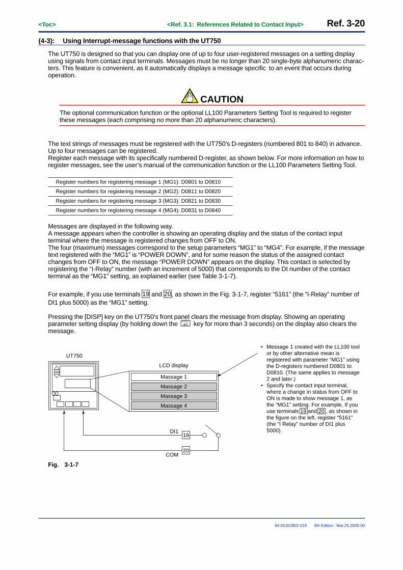
Ref. 3-20<Toc> <Ref. 3.1: References Related to Contact Input>
IM 05J01B02-01E 5th Edition : Mar.25,2005-00
(4-3): Using Interrupt-message functions with the UT750
The UT750 is designed so that you can display one of up to four user-registered messages on a setting displayusing signals from contact input terminals. Messages must be no longer than 20 single-byte alphanumeric charac-ters. This feature is convenient, as it automatically displays a message specific to an event that occurs duringoperation.
CAUTIONThe optional communication function or the optional LL100 Parameters Setting Tool is required to registerthese messages (each comprising no more than 20 alphanumeric characters).
The text strings of messages must be registered with the UT750’s D-registers (numbered 801 to 840) in advance.Up to four messages can be registered.Register each message with its specifically numbered D-register, as shown below. For more information on how toregister messages, see the user’s manual of the communication function or the LL100 Parameters Setting Tool.
Register numbers for registering message 1 (MG1): D0801 to D0810
Register numbers for registering message 2 (MG2): D0811 to D0820
Register numbers for registering message 3 (MG3): D0821 to D0830
Register numbers for registering message 4 (MG4): D0831 to D0840
Messages are displayed in the following way.A message appears when the controller is showing an operating display and the status of the contact inputterminal where the message is registered changes from OFF to ON.The four (maximum) messages correspond to the setup parameters “MG1” to “MG4”. For example, if the messagetext registered with the “MG1” is “POWER DOWN”, and for some reason the status of the assigned contactchanges from OFF to ON, the message “POWER DOWN” appears on the display. This contact is selected byregistering the “I-Relay” number (with an increment of 5000) that corresponds to the DI number of the contactterminal as the “MG1” setting, as explained earlier (see Table 3-1-7).
For example, if you use terminals 19 and 20, as shown in the Fig. 3-1-7, register “5161” (the “I-Relay” number ofDI1 plus 5000) as the “MG1” setting.
Pressing the [DISP] key on the UT750’s front panel clears the message from display. Showing an operatingparameter setting display (by holding down the SET/ENT key for more than 3 seconds) on the display also clears themessage.
Massage 1
LCD display
UT750
Massage 4
Massage 3
Massage 2
19DI1
COM20
• Message 1 created with the LL100 tool or by other alternative mean is registered with parameter “MG1” using the D-registers numbered D0801 to D0810. (The same applies to message 2 and later.)
• Specify the contact input terminal, where a change in status from OFF to ON is made to show message 1, as the “MG1” setting. For example, If you use terminals 19 and 20 , as shown in the figure on the left, register “5161” (the “I Relay” number of DI1 plus 5000).
Fig. 3-1-7
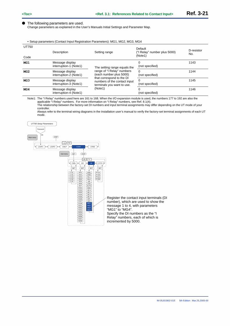
<Toc> <Ref. 3.1: References Related to Contact Input> Ref. 3-21
IM 05J01B02-01E 5th Edition : Mar.25,2005-00
● The following parameters are used.Change parameters as explained in the User’s Manuals Initial Settings and Parameter Map.
• Setup parameters (Contact Input Registration Parameters): MG1, MG2, MG3, MG4
UT750
Code
Description Setting range
The setting range equals the range of “I Relay” numbers(each number plus 5000)that correspond to the DInumbers of the contact inputterminals you want to use.(Note1)
Default(“I Relay” number plus 5000)(Note1)
D-resistor No.
11430(not specified)
MG1 Message display interruption-1 (Note1)
11440(not specified)
MG2 Message display interruption-2 (Note1)
11450(not specified)
MG3 Message display interruption-3 (Note1)
11460(not specified)
MG4 Message display interruption-4 (Note1)
Note1: The “I Relay” numbers used here are 161 to 168. When the I/O expansion module is used, the numbers 177 to 192 are also theapplicable “I Relay” numbers. For more information on “I Relay” numbers, see Ref. 8.1(4).The relationship between the factory-set DI numbers and input terminal assignments may differ depending on the UT mode of yourcontroller.Always refer to the terminal wiring diagrams in the Installation user’s manual to verify the factory-set terminal assignments of each UTmode.
LOOP2LOOP1 CMLP
OK
CONF UTMD
DISP
C.S4C.S3C.S2C.S1
C.S5
CSEL DO DI C.PYS
DO4DO3DO2DO1
DO5
DO7DO6
R154R153R152R151
R155
R157R156
R253R252R251R158
R254
R256R255
R258R257
A/M1
SETSETSET SET
PY2BPY2APY1BPY1A
SET
CASS/RR/L2
A/M2R/L1
DISP
SP.3
AUTO
SP.1SP.0MAN
SP.2
MG4
DP1
MG2MG1DP2
MG3
UT750 Setup Parameters
Main menu
Sub menu
Password
Register the contact input terminals (DI number), which are used to show the message 1 to 4, with parameters “MG1” to “MG4”.Specify the DI numbers as the “I Relay” numbers, each of which is incremented by 5000.

Ref. 3-22<Toc> <Ref. 3.1: References Related to Contact Input>
IM 05J01B02-01E 5th Edition : Mar.25,2005-00
(4-4): Using Interrupt-operating display functions with the UT750
The UT750 is designed so that you can display the expected operating display using signals from contact inputterminals. This feature is convenient, as it automatically displays the expected operating display specific to anevent that occurs during operation.
CAUTIONThe optional LL 200 custom computation building tool is required to use this function.Refer to the User’s manual of LL200 for more details.
The expected operating display appears when the status of the contact input terminal where the operating displayis registered changes from OFF to ON.The operating display correspond to the setup parameters “DP1” or “DP2”. This contact is selected by registeringthe “I-Relay” number (with an increment of 5000) that corresponds to the DI number of the contact terminal as the“DP1” or “DP2” setting, as explained earlier (see Table 3-1-7).
Pressing the [DISP] key on the UT750’s front panel displays the next operating display.
● The following parameters are used.Change parameters as explained in the User’s Manuals Initial Settings and Parameter Map.
• Setup parameters (Contact Input Registration Parameters): DP1, DP2
UT750
Code
Description Setting rangeDefault(“I Relay” number plus 5000)(Note1)
D-resistor No.
11410(not specified)
DP1 Operating display interruption-1 (Note1)
11420(not specified)
DP2 Operating display interruption-2 (Note1)
The setting range equals the range of “I Relay” numbers(each number plus 5000) that correspond to the DI numbers of the contact input terminals you want to use. (Note1)
Note1: The “I Relay” numbers used here are 161 to 168. When the I/O expansion module is used, the numbers 177 to 192 are also theapplicable “I Relay” numbers. For more information on “I Relay” numbers, see Ref. 8.1(4).The relationship between the factory-set DI numbers and input terminal assignments may differ depending on the UT mode of yourcontroller.Always refer to the terminal wiring diagrams in the Installation user’s manual to verify the factory-set terminal assignments of each UTmode.

<Toc> <Ref. 3.1: References Related to Contact Input> Ref. 3-23
IM 05J01B02-01E 5th Edition : Mar.25,2005-00
LOOP2LOOP1 CMLP
OK
CONF UTMD
DISP
C.S4C.S3C.S2C.S1
C.S5
CSEL DO DI C.PYS
DO4DO3DO2DO1
DO5
DO7DO6
R154R153R152R151
R155
R157R156
R253R252R251R158
R254
R256R255
R258R257
A/M1
SETSETSET SET
PY2BPY2APY1BPY1A
SET
CASS/RR/L2
A/M2R/L1
DISP
SP.3
AUTO
SP.1SP.0MAN
SP.2
MG4
DP1
MG2MG1DP2
MG3
UT750 Setup Parameters
Main menu
Sub menu
Password
Register the contact input terminals (DI number), which are used to show the operating displays you created, with parameters “DP1” and “DP2”. Specify the DI numbers as the “I Relay” numbers, each of which is incremented by 5000.

Ref. 3-24<Toc> <Ref. 3.1: References Related to Contact Input>
IM 05J01B02-01E 5th Edition : Mar.25,2005-00
When the UP series controllers
<<Ref. 3.1: References Related to Contact Input>>Ref.3.1(5) Changing contact input functions for the UP35�
UP35� comes with three contact input terminals that can be used, for example, to change the operation mode.When the controller is shipped from the factory, the terminals are set to the functions “starting and stopping(Reset) program-1 operation” and “starting and stopping (Reset) program-2 operation.”
The terminal numbers are 18, 19 and 20 (common terminals). Terminal 18 is assigned as DI1 (for contact input 1)and terminal 19 as DI2 (for contact input 2). (See the terminal wiring diagrams in the Installation user’s manual.)
< UP35� Terminal Arrangement >
Correspondence between parameter DIS and external contact input functions
DI1
DI2
COM
Contact
19
18
20
UPWhen DIS=3
Common
Start program 1 when DI1 = ONReset program 1 when DI1 = OFF
Hold program when DI2 = ON Cancel hold when DI2 = OFF
When DIS=2
Hide setup parameter lock when DI1 = ONShow setup parameter lock when DI1 = OFF
Common
When DIS=1
Start program 1 when DI1 = ONReset program 1 when DI1 = OFF
Start program 2 when DI2 = ONReset program 2 when DI2 = OFF
Common
When DIS=OFF (Factory-shipped setting)
Common
No functionNo function
No function
1
2
3
4
5
6
7
8
9
10
41
42
43
44
45
46
47
48
49
50
31
32
33
34
35
36
37
38
39
40
21
22
23
24
25
26
27
28
29
30
11
12
13
14
15
16
17
18
19
20
DI1(No.19)
Terminal
* DIS is a setup parameter. Changing DIS setpoint allows you to change the function of external contact input.
DI2(No.18)
COM.(No.20)
Fig. 3-1-8 UP35� Contact Input Terminals
The UP35� is designed so that the functions assigned to their contact input terminals can be changed using the“DIS” setup parameter. If necessary, reassign functions by referring to the table in the Fig. 3-1-8.

<Toc> <Ref. 3.1: References Related to Contact Input> Ref. 3-25
IM 05J01B02-01E 5th Edition : Mar.25,2005-00
● The following parameters are used.Change parameters as explained in the User’s Manuals Initial Settings and Parameter Map.
• Setup parameters (I/O-related Paramerters): DIS
Description Setting range
OFF: Turns contact input off.
1: • DI1: Starts (on)/stops (off) program-1 operation.• DI2: Starts (on)/stops (off) program-2 operation.
2: • DI1: Hides (on)/shows (off) the LOCK setup parameter.
• DI2: Unused.3: • DI1: Starts (on)/stops (off) program-1 operation.
• DI2: Enables (on)/disables (off) the hold mode of program-1 operation.
932OFF (0)
Default D-register No.
UP35�
Display
DI function selection(DIS)
Note1: The program-1 (or -2) starts program operation when the contact is ON and stop (reset) program operation when the contact is OFF.Note2: The “Keylock (LOCK)” setup parameter setting display is hidden when the DI1 contact is ON and is shown when the contact is OFF.
This function of hiding the keylock parameter using external input is an extra safeguard against erroneous operations.Note3: The Hold mode is selected when the contact is ON and the Hold status is removed when the contact is OFF.
Part of the parameter map for the UP35� is shown below. Refer to it when changing parameter values in order toaccess the desired parameter setting display.
CAUTIONIf you change any contact input terminal assignment, check that the new assignment agrees with the currentwiring. If necessary, rewire the terminals.
Operating display
Setup parameter map
Note1: Pressing the key on the [OP.PA] display changes to the “ ” operating parameter setting display.
Note2: If you have set a password, “[FUNC]” is not displayed unless the correct password is entered.
Note3: The displays and can be switched with or key.
(Note1)
(Note2)
SET/ENTSET/ENT
SET/ENTSET/ENT
SET/ENTSET/ENT
SET/ENTSET/ENT
SET/ENTSET/ENT
(Note3)
SET/ENTkey 3 sec. or more
1. Call up the “I/O” display.(Refer to the Note 1 to 3 above)
2. Press the key to display the parameter “DIS” setting display.
SET/ENT
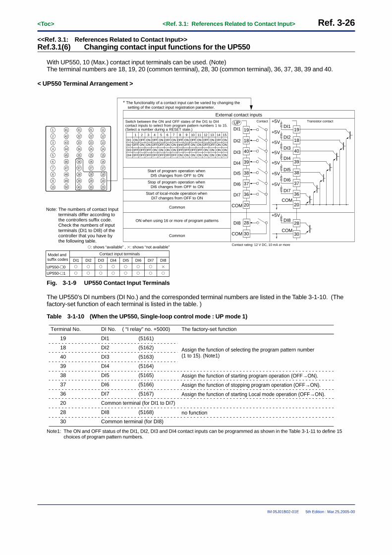
Ref. 3-26<Toc> <Ref. 3.1: References Related to Contact Input>
IM 05J01B02-01E 5th Edition : Mar.25,2005-00
<<Ref. 3.1: References Related to Contact Input>>Ref.3.1(6) Changing contact input functions for the UP550
With UP550, 10 (Max.) contact input terminals can be used. (Note)The terminal numbers are 18, 19, 20 (common terminal), 28, 30 (common terminal), 36, 37, 38, 39 and 40.
< UP550 Terminal Arrangement >
1
2
3
4
5
6
7
8
9
10
41
42
43
44
45
46
47
48
49
50
31
32
33
34
35
36
37
38
39
40
21
22
23
24
25
26
27
28
29
30
11
12
13
14
15
16
17
18
19
20
* The functionality of a contact input can be varied by changing the setting of the contact input registration parameter.
Note: The numbers of contact Input terminals differ according to the controllers suffix code. Check the numbers of input terminals (DI1 to DI8) of the controller that you have by the following table.
Contact input terminalsModel and suffix codes DI1 DI2 DI3 DI4 DI5 DI6 DI8
UP550-�1
UP550-�0
�
�
�
�
�
�
�
�
�
�
�
�
�
�
DI7
�
�
�: shows “available” , �: shows “not available”
External contact inputs
Common
Start of local-mode operation when DI7 changes from OFF to ON
Common
Stop of program operation when DI6 changes from OFF to ON
Start of program operation when DI5 changes from OFF to ON
ON when using 16 or more of program patterns
DI1
DI2
1 2 3 4
ONONOFFOFF
ONON OFF
OFF
5 6 7 8
ONONOFFOFF
ONON OFF
OFF
DI3
DI4
OFF
OFF
OFF
OFF
OFF
OFF
ON
OFF
ON
OFF
ON
OFF
ON
OFF
OFF
ON
9 10 11 12
ONONOFFOFF
ONON OFF
OFF
13 14 15
ONONOFFOFF
ONON
OFF
ON
OFF
ON
OFF
ON
ON
ON
ON
ON
ON
ON
ON
ON
Switch between the ON and OFF states of the DI1 to DI4 contact inputs to select from program pattern numbers 1 to 15. (Select a number during a RESET state.) 19
18
40
39
38
37
20
28
30
DI1
DI2
DI3
DI4
DI5
DI6
COM
COM
DI8
19
18
40
39
38
37
20
28
30
DI1
DI2
DI3
DI4
DI5
DI6
COM
COM
DI8
+5V
+5V
+5V
+5V
+5V
+5V
36DI7 36DI7
+5V
+5V
Contact Transistor contactUP
Contact rating: 12 V DC, 10 mA or more
Fig. 3-1-9 UP550 Contact Input Terminals
The UP550’s DI numbers (DI No.) and the corresponded terminal numbers are listed in the Table 3-1-10. (Thefactory-set function of each terminal is listed in the table. )
Table 3-1-10 (When the UP550, Single-loop control mode : UP mode 1)
Terminal No.
19
DI No.
DI1
The factory-set function
Assign the function of selecting the program pattern number(1 to 15). (Note1)
18 DI2
40 DI3
no function
39 DI4
38 DI5
37 DI6
20 Common terminal (for DI1 to DI7)
36 DI7
28 DI8
Assign the function of starting program operation (OFF→ON).
Assign the function of stopping program operation (OFF→ON).
Assign the function of starting Local mode operation (OFF→ON).
30 Common terminal (for DI8)
( “I relay” no. +5000)
(5161)
(5162)
(5163)
(5164)
(5165)
(5166)
(5167)
(5168)
Note1: The ON and OFF status of the DI1, DI2, DI3 and DI4 contact inputs can be programmed as shown in the Table 3-1-11 to define 15choices of program pattern numbers.
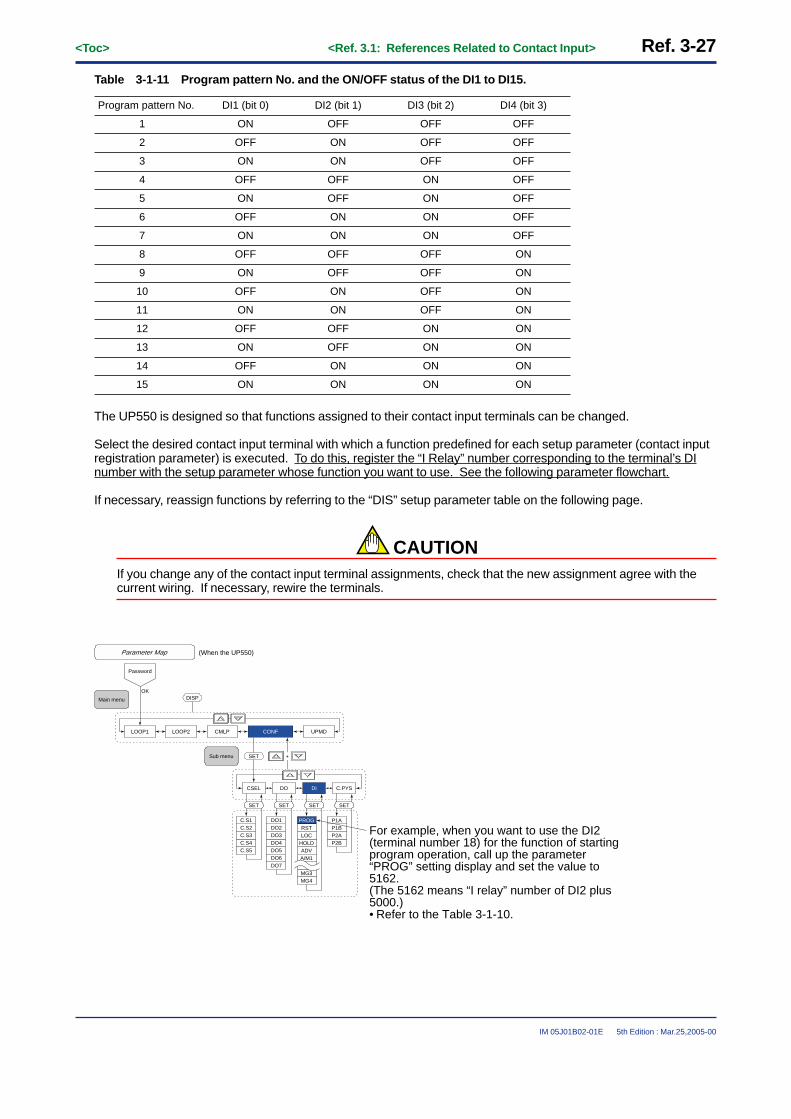
<Toc> <Ref. 3.1: References Related to Contact Input> Ref. 3-27
IM 05J01B02-01E 5th Edition : Mar.25,2005-00
Table 3-1-11 Program pattern No. and the ON/OFF status of the DI1 to DI15.
1
DI1 (bit 0)Program pattern No.
ON
DI2 (bit 1)
OFF
DI3 (bit 2)
OFF
DI4 (bit 3)
OFF
2 OFF ON OFF OFF
3 ON ON OFF OFF
4 OFF OFF ON OFF
5 ON OFF ON OFF
6 OFF ON ON OFF
7 ON ON ON OFF
8 OFF OFF OFF ON
9 ON OFF OFF ON
10 OFF ON OFF ON
11 ON ON OFF ON
12 OFF OFF ON ON
13 ON OFF ON ON
14 OFF ON ON ON
15 ON ON ON ON
The UP550 is designed so that functions assigned to their contact input terminals can be changed.
Select the desired contact input terminal with which a function predefined for each setup parameter (contact inputregistration parameter) is executed. To do this, register the “I Relay” number corresponding to the terminal’s DInumber with the setup parameter whose function you want to use. See the following parameter flowchart.
If necessary, reassign functions by referring to the “DIS” setup parameter table on the following page.
CAUTIONIf you change any of the contact input terminal assignments, check that the new assignment agree with thecurrent wiring. If necessary, rewire the terminals.
Main menu
Sub menu
LOOP2LOOP1 CMLP
OK
Parameter Map
Password
(When the UP550)
CONF UPMD
DISP
C.S4C.S3C.S2C.S1
C.S5
CSEL DO DI C.PYS
DO4DO3DO2DO1
DO5
DO7DO6
SETSETSET SET
P2BP2AP1BP1A
SET +
PROG
HOLDLOCRST
ADV
MG3
A/M1
MG4
For example, when you want to use the DI2 (terminal number 18) for the function of starting program operation, call up the parameter “PROG” setting display and set the value to 5162.(The 5162 means “I relay” number of DI2 plus 5000.)• Refer to the Table 3-1-10.

Ref. 3-28<Toc> <Ref. 3.1: References Related to Contact Input>
IM 05J01B02-01E 5th Edition : Mar.25,2005-00
● The following parameters are used.Change parameters as explained in the User’s Manuals Initial Settings and Parameter Map.
• Setup parameters (Contact Input Registration Parameters): PROG, RST, LOC, HOLD, etc.
UP550
Code
Description Setting range
11475165 (DI5)
Default (“I relay” number plus 5000.)(Note1)
D-register No.
PROG Start of program operation(When “DIn” changes from OFF to ON) (Note2)
11485166(DI6)
RST Stop of program operation(When “DIn” changes from OFF to ON) (Note2)
11495167(DI7)
LOC Start of local-mode operation(When “DIn” changes from OFF to ON) (Note2)
11500(not specified)
HOLD Start of hold-mode operation(When “DIn” changes from OFF to ON) (Note2)
11510(not specified)
ADV Advance of segment(When “DIn” changes from OFF to ON) (Note2)
The setting range equals the range of “I Relay” numbers (each number plus 5000) that correspond to the DI numbers of the contact input terminals you want to use. (Note1)
The relationship between the DI numbers and the “I Relay” numbers are as follows.
DI1: 5161 DI2: 5162 DI3: 5163 DI4: 5164 DI5: 5165 DI6: 5166 DI7: 5167 DI8: 5168
11520(not specified)
A/M1 Loop-1 AUTO/MAN switching(AUTO when contact input is ON; MAN when contact input is OFF)
11530 (not specified)
A/M2 Loop-2 AUTO/MAN switching(AUTO when contact input is ON; MAN when contact input is OFF)
11540 (not specified)
L/C LOCAL/CASCADE switchingNot used for single-loop control.
11555161(DI1)
PTN.0 Bit 0 of program pattern number (Note3)
11565162(DI2)
PTN.1 Bit 1 of program pattern number (Note3)
11575163(DI3)
PTN.2 Bit 2 of program pattern number (Note3)
11585164(DI4)
PTN.3 Bit 3 of program pattern number (Note3)
11595168(DI8)
PTN.4 Bit 4 of program pattern number (Note3)
11660 (not specified)
MG1 Interruptive message display 1
11670 (not specified)
MG2 Interruptive message display 2
11680 (not specified)
MG3 Interruptive message display 3
11690 (not specified)
MG4 Interruptive message display 4
Note1: The “I Relay” numbers used here are 161 to 168. DI numbers for contact input terminals are specified by these “I Relay” numbers eachof which is incremented by 5000. For more information on “I Relay” numbers, see Ref. 8.1(4).The relationship between the factory-set DI numbers and input terminal assignments may differ depending on the UP mode of yourcontroller. Always refer to the terminal wiring diagrams in the Installation user’s manual to verify the factory-set terminal assignments ofeach UP mode.
Note2: Each mode is executed when the state of the contact input changes from OFF to ON.Note3: Refer to the table 3-1-11.

<Toc> <Ref. 3.1: References Related to Contact Input> Ref. 3-29
IM 05J01B02-01E 5th Edition : Mar.25,2005-00
<<Ref. 3.1: References Related to Contact Input>>Ref.3.1(7) Changing contact input functions for the UP750
(7-1): Changing contact input functions for the UP750
With UP750, 8 (Max.) contact input terminals can be used. (Note)The terminal numbers are 18, 19, 20 (common terminal), 36, 37, 38, 39 and 40.
If these do not suffice your needs, using I/O expansion modules increases the number of available contact inputsto a maximum of 23. See “(7-2): Using the I/O Expansion module with the UP750.”
< UP750 Terminal Arrangement >
1
2
3
4
5
6
7
8
9
10
41
42
43
44
45
46
47
48
49
50
31
32
33
34
35
36
37
38
39
40
21
22
23
24
25
26
27
28
29
30
11
12
13
14
15
16
17
18
19
20
* The functionality of a contact input can be varied by changing the setting of the contact input registration parameter.
External contact inputs
Common
Start of local-mode operation when DI7 changes from OFF to ON
Stop of program operation when DI6 changes from OFF to ON
Start of program operation when DI5 changes from OFF to ON
DI1
DI2
1 2 3 4
ONONOFFOFF
ONON OFF
OFF
5 6 7 8
ONONOFFOFF
ONON OFF
OFF
DI3
DI4
OFF
OFF
OFF
OFF
OFF
OFF
ON
OFF
ON
OFF
ON
OFF
ON
OFF
OFF
ON
9 10 11 12
ONONOFFOFF
ONON OFF
OFF
13 14 15
ONONOFFOFF
ONON
OFF
ON
OFF
ON
OFF
ON
ON
ON
ON
ON
ON
ON
ON
ON
Switch between the ON and OFF states of the DI1 to DI4 contact inputs to select from program pattern numbers 1 to 15. (Select a number during a RESET state.) 19
18
40
39
38
37
20
DI1
DI2
DI3
DI4
DI5
DI6
COM
19
18
40
39
38
37
20
DI1
DI2
DI3
DI4
DI5
DI6
COM
+5V
+5V
+5V
+5V
+5V
+5V
36DI7 36DI7
+5V
Contact Transistor contactUP
Contact rating: 12 V DC, 10 mA or more
Fig. 3-1-10 UP750 Contact Input Terminals
The UP750’s DI numbers (DI No.) and the corresponded terminal numbers are listed in the Table 3-1-12. (Thefactory-set function of each terminal is listed in the table. )
Table 3-1-12 (When the Single-loop control mode : UP mode 1)
Terminal No.
19
DI No.
DI1
The factory-set function
Assign the function of selecting the program pattern number(1 to 15). (Note1)
18 DI2
40 DI3
no function
39 DI4
38 DI5
37 DI6
20 Common terminal (for DI1 to DI7)
36 DI7
28 DI8
Assigns the function of starting program operation (OFF→ON).
Assigns the function of stopping program operation (OFF→ON).
Assigns the function of starting Local mode operation (OFF→ON).
30 Common terminal (for DI8)
( “I relay” no. +5000)
(5161)
(5162)
(5163)
(5164)
(5165)
(5166)
(5167)
(5168)
Note1: The ON and OFF status of the DI1, DI2, DI3 and DI4 contact inputs can be programmed as shown in the Table 3-1-13 to define 15choices of program pattern numbers.

Ref. 3-30<Toc> <Ref. 3.1: References Related to Contact Input>
IM 05J01B02-01E 5th Edition : Mar.25,2005-00
Table 3-1-13
1
DI1 (bit 0)Program pattern No.
ON
DI2 (bit 1)
OFF
DI3 (bit 2)
OFF
DI4 (bit 3)
OFF
2 OFF ON OFF OFF
3 ON ON OFF OFF
4 OFF OFF ON OFF
5 ON OFF ON OFF
6 OFF ON ON OFF
7 ON ON ON OFF
8 OFF OFF OFF ON
9 ON OFF OFF ON
10 OFF ON OFF ON
11 ON ON OFF ON
12 OFF OFF ON ON
13 ON OFF ON ON
14 OFF ON ON ON
15 ON ON ON ON
TIPWhen you want to define the program pattern #100, set the ON/OFF status of “bit 0” to “bit 6” as follows.(Refer to the parameter list on page Ref. 3-31 for the “bit 4” to “bit 8”.)
< bit 0 >20
=1
(OFF)
< bit 1 >21
=2
(OFF)
< bit 2 >22
=4
ON
< bit 3 >23
=8
(OFF)
< bit 4 >24
=16
(OFF)
< bit 5 >25
=32
ON
< bit 6 >26
=64
ON

<Toc> <Ref. 3.1: References Related to Contact Input> Ref. 3-31
IM 05J01B02-01E 5th Edition : Mar.25,2005-00
The UP750 is designed so that functions assigned to its contact input terminals can be changed. In addition,functions can be assigned to the terminals of an optional I/O expansion module.Select the desired contact input terminal with which a function predefined for each setup parameter (contact inputregistration parameter) is executed. To do this, register the “I Relay” number corresponding to the terminal’s DInumber with the setup parameter whose you want to see. Use the following parameter map to reassign terminalfunctions as necessary.
CAUTIONIf you change any of the contact input terminal assignments, check that the new assignment agrees with thecurrent wiring. If necessary, rewire the terminals.
LOOP2LOOP1 CMLP
OK
Set up Parameter Map
CONF UTMD
DISP
C.S4C.S3C.S2C.S1
C.S5
CSEL DO DI C.PYS
DO4DO3DO2DO1
DO5
DO7DO6
R154R153R152R151
R155
R157R156
R253R252R251R158
R254
R256R255
R258R257
PROG
SETSETSET SET
PY2BPY2APY1BPY1A
SET
A/M1ADV
HOLD
RSTLOC
DISP
A/M2
MG4MG3
Main menu
Sub menu
Password
For example, when you want to use the DI2 (terminal number 18) for the function of program operation starting, call up the parameter “PROG” setting display and set the value to 5162.(The 5162 means “I relay” number of DI2 plus 5000.)• Refer to the Table 3-1-12.

Ref. 3-32<Toc> <Ref. 3.1: References Related to Contact Input>
IM 05J01B02-01E 5th Edition : Mar.25,2005-00
● The following parameters are used.Change parameters as explained in the User’s Manuals Initial Settings and Parameter Map.
• Setup parameters (Contact Input Registration Parameters): PROG, RST, LOC, HOLD, etc. <<1/2>>
UP750
Code
Description Setting range
11475165 (DI5)
Default (“I relay” number plus 5000.)(Note1)
D-register No.
PROG Start of program operation(When “DIn” changes from OFF to ON) (Note2)
11485166(DI6)
RST Stop of program operation(When “DIn” changes from OFF to ON) (Note2)
11495167(DI7)
LOC Start of local-mode operation(When “DIn” changes from OFF to ON) (Note2)
11500(not specified)
HOLD Start of hold-mode operation(When “DIn” changes from OFF to ON) (Note2)
11510(not specified)
ADV Advance of segment(When “DIn” changes from OFF to ON) (Note2)
The setting range equals the range of “I Relay” numbers (each number plus 5000) that correspond to the DI numbers of the contact input terminals you want to use. (Note1)
The relationship between the DI numbers and the “I Relay” numbers are as follows.
DI1: 5161 DI2: 5162 DI3: 5163 DI4: 5164 DI5: 5165 DI6: 5166 DI7: 5167 DI8: 5168
11520(not specified)
A/M1 Loop-1 AUTO/MAN switching(AUTO when contact input is ON; MAN when contact input is OFF)
11530 (not specified)
A/M2 Loop-2 AUTO/MAN switching(AUTO when contact input is ON; MAN when contact input is OFF)
11540 (not specified)
L/C LOCAL/CASCADE switchingNot used for single-loop control.
11555161(DI1)
PTN.0 Bit 0 of program pattern number (Note3)
11565162(DI2)
PTN.1 Bit 1 of program pattern number (Note3)
11575163(DI3)
PTN.2 Bit 2 of program pattern number (Note3)
11585164(DI4)
PTN.3 Bit 3 of program pattern number (Note3)

<Toc> <Ref. 3.1: References Related to Contact Input> Ref. 3-33
IM 05J01B02-01E 5th Edition : Mar.25,2005-00
• Setup parameters (Contact Input Registration Parameters): PROG, RST, LOC, HOLD, etc. <<2/2>>
UP750
Code
Description Setting rangeDefault (“I relay” number plus 5000.)(Note1)
D-register No.
11590 (not specified)
PTN.4 Bit 4 of program pattern number (Note3)
11600 (not specified)
PTN.5 Bit 5 of program pattern number (Note3)
11610 (not specified)
PTN.6 Bit 6 of program pattern number (Note3)
11620 (not specified)
PTN.7 Bit 7 of program pattern number (Note3)
11630 (not specified)
PTN.8 Bit 8 of program pattern number (Note3)
11660 (not specified)
MG1 Message display Interruption-1
11670 (not specified)
MG2 Message display Interruption-2
11680 (not specified)
MG3 Message display Interruption-3
11690 (not specified)
MG4 Message display Interruption-4
Use the I/O expansion module for specifying the “PTN.4” to “PTN.8” setupparameters.
Note1: The “I Relay” numbers used here are 161 to 168. DI numbers for contact input terminals are specified by these “I Relay” numbers eachof which is incremented by 5000. For more information on “I Relay” numbers, see Ref. 8.1(4).The relationship between the factory-set DI numbers and input terminal assignments may differ depending on the UP mode of yourcontroller. Always refer to the terminal wiring diagrams in the Installation user’s manual to verify the factory-set terminal assignments ofeach UP mode.
Note2: Each mode is executed when the state of the contact input changes from OFF to ON.Note3: Refer to the table 3-1-13.

Ref. 3-34<Toc> <Ref. 3.1: References Related to Contact Input>
IM 05J01B02-01E 5th Edition : Mar.25,2005-00
(7-2): Using contact I/O expansion module with the UP750
The UP750 comes with eight contact input terminals (including one common terminal): terminals 18, 19, 20(common terminal), 36, 37, 38, 39 and 40. If these do not suffice your needs, using I/O expansion modulesincrease the number of available contact inputs to a maximum of 23 (Note1).Up to two expansion modules can be installed at a time. Each has eight contact inputs and eight contact outputs.Therefore, connecting two modules to the controller, provides a total of 23 inputs, 16 (8 x 2) inputs from the twomodules and 7 standard inputs from the controller (actually there are only seven standard inputs available be-cause terminal 20 of the above-mentioned eight terminals is reserved as a common terminals.)Note1: Requires Yokogawa’s optional add-on module for the µFA20 compact program controller.
INPUT 24V DC 5mA
OUTPUT
INPUT 24V DC 5mA
OUTPUT
OUTPUT
SUPPLY
A B SHIELD24V DC 0.1A OUTPUT 240V AC 2A/24V DC 2A • BUS
INPUT
8 Inputterminals
8 Outputterminals
I/O Expansion Module1
8 Inputterminals
8 Outputterminals
I/O Expansion Module2
µ-BUS Communication MAX.15m
UP750
INPUT
POWERRUN
POWERRUN
123
4
OUTPUT
SUPPLY
A B SHIELD24V DC 0.1A OUTPUT 240V AC 2A/24V DC 2A • BUS
POWERRUN
123
4
1 2 3 4
5 6 7 8
9 10 11 12
51 52 53 54
55 56 57 58
1 2 3 4
5 6 7 8
9 10 11 12
51 52 53 54
55 56 57 58
Fig. 3-1-11 I/O Expansion Module Wiring Outline
The connectable contact I/O expansion modules (optional) are shown below.
P2ER1-20J
Source VoltageModel
AC100 to 240V
Output type
Relay contact output
P2ET1-20J AC100 to 240V Transistor contact output
P2ER6-20J DC24V Relay contact output
P2ET6-20J DC24V Transistor contact output

<Toc> <Ref. 3.1: References Related to Contact Input> Ref. 3-35
IM 05J01B02-01E 5th Edition : Mar.25,2005-00
CAUTIONThe factory-set function of each terminal of I/O Expansion module is listed in the table below. Reassignfunctions by referring to the “Function changing procedure” if necessary.
Input code
RDI101
RDI102
RDI103
RDI104
RDI105
RDI106
RDI107
RDI108
Function
Starting HOLD operation
Starting ADVANCE operation
Switching Auto/Manual operation
Switching program pattern numbers
Into “HOLD” when the contact status changed from OFF to ON
Advance to the next segment when the contact status changed from OFF to ON
ON: AUTOOFF: MANUAL
Up to #300 program pattern can be selected (Note)
Remarks
-
-
Control output value can bechanged by �/� key operation when MANUAL operation.
Program patterns with the following numerals added to numbers selected by other contact turned on and off -- are selected:• RDI104 turned on: +16• RDI105 turned on: +32• RDI106 turned on: +64• RDI107 turned on: +128• RDI108 turned on: +256 (Note)
Note: For example, when you want to select the program pattern #17, set the ON/OFF status of the DIs as followings,DI: ON, DI2: OFF, DI3: OFF, DI4: OFF, RDI104: ON and RDI105 to RDI108: OFF.
Function changing program
The relationship between the contact input terminals of an I/O expansion module and the I Relay numbers is givenin the table below. To assign contact-switched functions to the module’s terminals, follow the steps below.
1) Select a contact-switched function to assign to a module terminal from the table of setup parameters(contact input registration parameters) in Page Ref.3-30 and Ref.3-31.
2) Select a terminal from those of the I/O expansion module listed in the table below.3) Show the setting display of the setup parameter selected in step 1 and register the I Relay number (with an
increment of 5000) of the terminal selected in step 2.
For example, register “5177” with the “HOLD” setup parameter to assign the starting HOLD operation function toINPUT1.

Ref. 3-36<Toc> <Ref. 3.1: References Related to Contact Input>
IM 05J01B02-01E 5th Edition : Mar.25,2005-00
Table 3-1-14
INPUT1
“I” relay No. (+5000)Input terminals
I/O expansion module 1
I/O expansion module 2
5177
Code (Refer to the I-relay Map) (Note)
RDI101
INPUT2 5178 RDI102
INPUT3 5179 RDI103
INPUT4 5180 RDI104
INPUT5 5181 RDI105
INPUT6 5182 RDI106
INPUT7 5183 RDI107
INPUT8 5184 RDI108
INPUT1 5185 RDI201
INPUT2 5186 RDI202
INPUT3 5187 RDI203
INPUT4 5188 RDI204
INPUT5 5189 RDI205
INPUT6 5190 RDI206
INPUT7 5191 RDI207
INPUT8 5192 RDI208
Note: See Ref.8.1(4) I-relay Outline and I-relay Map.
(7-3): Using Interrupt-message functions with the UP750
The UP750 is designed so that you can display one of up to four user-registered messages on a setting displayusing signals from contact input terminals. Messages must be no longer than 20 single-byte alphanumeric charac-ters. This feature is convenient, as it automatically displays a message specific to an event that occurs duringoperation.
CAUTIONThe optional communication function or the optional LL100 Parameters Setting Tool is required to registerthese messages (each comprising no more than 20 alphanumeric characters).
The text strings of messages must be registered with the UP750’s D-registers (numbered 801 to 840) in advance.Up to four messages can be registered.Register each message with its specifically numbered D-register, as shown below. For more information on how toregister messages, see the user’s manual of the communication function or the LL100 Parameters Setting Tool.
Register numbers for registering message 1 (MG1): D0801 to D0810
Register numbers for registering message 2 (MG2): D0811 to D0820
Register numbers for registering message 3 (MG3): D0821 to D0830
Register numbers for registering message 4 (MG4): D0831 to D0840

<Toc> <Ref. 3.1: References Related to Contact Input> Ref. 3-37
IM 05J01B02-01E 5th Edition : Mar.25,2005-00
Messages are displayed in the following way.A message appears when the controller is showing an operating display and the status of the contact inputterminal where the message is registered changes from OFF to ON.The four (maximum) messages correspond to the setup parameters “MG1” to “MG4”. For example, if the messagetext registered with the “MG1” is “POWER DOWN”, and for some reason the status of the assigned contactchanges from OFF to ON, the message “POWER DOWN” appears on the display. This contact is selected byregistering the “I-Relay” number (with an increment of 5000) that corresponds to the DI number of the contactterminal as the “MG1” setting, as explained earlier (see Table 3-1-12).
For example, if you use terminals 19 and 20, as shown in the Fig. 3-1-12, register “5161” (the “I-Relay” number ofDI1 plus 5000) as the “MG1” setting.
Pressing the [DISP] key on the UP750’s front panel clears the message from display. Showing an operatingparameter setting display (by holding down the
SET/ENT
key for more than 3 seconds) on the display also clears themessage.
Massage 1
LCD display
UP750
Massage 4
Massage 3
Massage 2
19DI1
COM20
• Message 1 created with the LL100 tool or by other alternative mean is registered with parameter “MG1” using the D-registers numbered D0801 to D0810. (The same applies to message 2 and later.)
• Specify the contact input terminal, where a change in status from OFF to ON is made to show message 1, as the “MG1” setting. For example, If you use terminals 19 and 20 , as shown in the figure on the left, register “5161” (the “I Relay” number of DI1 plus 5000).
Fig. 3-1-12

Ref. 3-38<Toc> <Ref. 3.1: References Related to Contact Input>
IM 05J01B02-01E 5th Edition : Mar.25,2005-00
● The following parameters are used.Change parameters as explained in the User’s Manuals Initial Settings and Parameter Map.
• Setup parameters (Contact Input Registration Parameters): MG1, MG2, MG3, MG4
UP750
Code
Description Setting range
The setting range equals the range of “I Relay” numbers(each number plus 5000)that correspond to the DInumbers of the contact inputterminals you want to use.(Note1)
Default(“I Relay” number plus 5000)(Note1)
D-resistor No.
11660(not specified)
MG1 Message display interruption-1 (Note1)
11670(not specified)
MG2 Message display interruption-2 (Note1)
11680(not specified)
MG3 Message display interruption-3 (Note1)
11690(not specified)
MG4 Message display interruption-4 (Note1)
Note1: The “I Relay” numbers used here are 161 to 168. When the I/O expansion module is used, the numbers 177 to 192 are also theapplicable “I Relay” numbers. For more information on “I Relay” numbers, see Ref. 8.1(4).The relationship between the factory-set DI numbers and input terminal assignments may differ depending on the UP mode of yourcontroller.Always refer to the terminal wiring diagrams in the Installation user’s manual to verify the factory-set terminal assignments of each UPmode.
LOOP2LOOP1 CMLP
OK
UP750 Setup Parameters
CONF UTMD
DISP
C.S4C.S3C.S2C.S1
C.S5
CSEL DO DI C.PYS
DO4DO3DO2DO1
DO5
DO7DO6
R154R153R152R151
R155
R157R156
R253R252R251R158
R254
R256R255
R258R257
PROG
SETSETSET SET
PY2BPY2APY1BPY1A
SET
ADVHOLD
RSTLOC
DISP
MG4
MG2MG1
MG3
Main menu
Sub menu
Password
Register the contact input terminals (DI number), which are used to show the message 1 to 4, with parameters “MG1” to “MG4”.Specify the DI numbers as the “I Relay” numbers, each of which is incremented by 5000.

<Toc> <Ref. 3.1: References Related to Contact Input> Ref. 3-39
IM 05J01B02-01E 5th Edition : Mar.25,2005-00
(7-4): Using Interrupt-operating display functions with the UP750
The UP750 is designed so that you can display the expected operating display using signals from contact inputterminals. This feature is convenient, as it automatically displays the expected operating display specific to anevent that occurs during operation.
CAUTIONThe optional LL 200 custom computation building tool is required to use this function.Refer to the User’s manual of LL200 for more details.
The expected operating display appears when the status of the contact input terminal where the operating displayis registered changes from OFF to ON.The operating display correspond to the setup parameters “DP1” or “DP2”. This contact is selected by registeringthe “I-Relay” number (with an increment of 5000) that corresponds to the DI number of the contact terminal as the“DP1” or “DP2” setting, as explained earlier (see Table 3-1-12).
Pressing the [DISP] key on the UP750’s front panel displays the next operating display.
● The following parameters are used.Change parameters as explained in the User’s Manuals Initial Settings and Parameter Map.
• Setup parameters (Contact Input Registration Parameters): DP1, DP2
UP750
Code
Description Setting rangeDefault(“I Relay” number plus 5000)(Note1)
D-resistor No.
11410(not specified)
DP1 Operating display interruption-1 (Note1)
11420(not specified)
DP2 Operating display interruption-2 (Note1)
The setting range equals the range of “I Relay” numbers(each number plus 5000) that correspond to the DI numbers of the contact input terminals you want to use. (Note1)
Note1: The “I Relay” numbers used here are 161 to 168. When the I/O expansion module is used, the numbers 177 to 192 are also theapplicable “I Relay” numbers. For more information on “I Relay” numbers, see Ref. 8.1(4).The relationship between the factory-set DI numbers and input terminal assignments may differ depending on the UP mode of yourcontroller. UP mode.

Ref. 3-40<Toc> <Ref. 3.2: References Related to Contact Output>
IM 05J01B02-01E 5th Edition : Mar.25,2005-00
Ref.3.2: References Related to Contact Output
IMPORTANT: Information in this reference applies to the following models.
UP750 UP550 UP35� UT750 UT5�� UT4�0 UT3��
UP750 UT750UP550 NONE (Note1) UT5�� NONE (Note1) NONE (Note1)
Note1: In the case of the UP35�, UT4�0 and UT3��, it is not possible to change the factory-set output contact assignments. Therefore, theexplanations on changing output contact assignments do not apply to these models.
Note2: Some of the functions discussed below may be limited to models with a specific suffix and/or option code. Each section will expresslyrefer to this limitative condition where it applies.
CAUTIONThe contact output functions of a UT/UP series controller are pre-assigned to their respective output terminalswhen the controller is shipped from the factory. The terminal assignments in each of the UT/UP modes aredefined in terms of the most frequently used. Check the controller model you will use and the factory-setterminal assignments for each controller mode of the model. To do this, see the terminal wiring diagrams inthe Installation user’s manual of each controller model and mode. Changes should only be made if yourequire any of the functions listed below or need to change any of the terminal numbers.
CAUTIONIf you change any of the contact output terminal assignments, check that the new assignment agrees with thecurrent wiring. If necessary, rewire the terminals.
This section contains reference information on the following aspects of contact output functions. Refer to thisinformation and only change parameter settings if necessary.
(1) Changing Contact Output Functions for the UT750, UT550, UT551 and UT520(2) Changing Contact Output Functions in the UP750 and UP550(3) Using the I/O Expansion Module with UT750 and UP750

<Toc> <Ref. 3.2: References Related to Contact Output> Ref. 3-41
IM 05J01B02-01E 5th Edition : Mar.25,2005-00
<<Ref. 3.2: References Related to Contact Output>>Ref.3.2(1) Changing Contact Output Functions for the UT750, UT550, UT551 and UT520
Each of UT750, UT550 and UT551 comes with nine contact output terminals and the UT520 comes with four.These include the common terminal. The terminals of the UT750, UT550 and UT551 are numbered 4, 5, 6, 7(common), 31, 32, 33, 34 and 35 (common); the terminals of the UT520 are numbered 4, 5, 6 and 7 (common).
Note: For the UT550, UT551 and UT520, the number of contact outputterminals varies depending on the model suffix codes. Checkwhether or not the related output terminals are present by referringto the table on the right. The UT750 provides all terminalsdescribed above.
Contact output terminalsModel and suffix codes DO1 DO2 DO3 DO7
UT55�-�1, UT551-�D
UT55�-�0, UT551-�A
�
�
�
�
�
�
�
x
UT55�-�2, UT551-�B � � � x
UT55�-�3, UT551-�C � � � �
UT55�-�4 �
�
�
�
�
�
x
x
UT520-07
UT520-00
� � � x
UT520-08 � � � x
DO6
�
x
x
�
x
x
x
x
DO5
�
x
x
�
x
x
x
x
DO4
�
x
x
�
x
x
x
x
Note: �: Present, x: Not present
1
2
3
4
5
6
7
8
9
10
41
42
43
44
45
46
47
48
49
50
31
32
33
34
35
36
37
38
39
40
21
22
23
24
25
26
27
28
29
30
11
12
13
14
15
16
17
18
19
20
6
5
4
7
DO1
DO2
DO3
COM
Relay
Alarm-1 output
Alarm-2 output
Alarm-3 output
Common
UT34
33
DO4
DO5Transistor
Alarm-3 output
(UT520 does not provide these terminals.)
Alarm-4 output
32DO6
31DO7
35COM
Alarm-4 output
Common
No functions
External contact output
The relationship between the DO numbers and output terminals of the UT750 in single-loop control is given inTable 3-2-1. This relationship is also given for the UT550, UT551 and UT520 in Tables 3-2-2 and 3-2-3, respec-tively.
When the controller is shipped from the factory, its contact output functions are pre-assigned to the DO terminalsas shown in Table 3-2-1 (for the UT750), Table 3-2-2 (for the UT550, UT551) or Table 3-2-3 (for the UT520).
Settings of each controller model for control modes other than single-loop control are given on the followingpages. Make sure the settings match the control mode you will use.
Table 3-2-1 Contact Output Terminals of UT750 (for Single-loop Control) and Their Factory-set Functions
Terminal No.
6
DO No.
DO1
Factory-set Function
Alarm-1 output
5 DO2 Alarm-2 output
Alarm-3 output (or cooling-side control output [Note1])
Unassigned
4 DO3
7 Common terminal (for DO1 to DO3)
34 DO4 Alarm-4 output (or cooling-side control output [Note1])
Output Type
Relay
Relay
Relay
Transistor
Transistor
33 DO5
Unassigned Transistor32 DO6
FAIL output Transistor31 DO7
35 Common terminal (for DO4 to DO7)
Note1: When heating/cooling control is selected as the option of the Control Output Selection parameter, cooling-side output is assigned toeither DO3 (relay output) or DO4 (open-collector transistor output).

Ref. 3-42<Toc> <Ref. 3.2: References Related to Contact Output>
IM 05J01B02-01E 5th Edition : Mar.25,2005-00
Table 3-2-2 Contact Output Terminals of UT550/UT551 (for Single-loop Control) and Their Factory-set Functions
Terminal No.
6
DO No.
DO1
Factory-set Function
Alarm-1 output
5 DO2 Alarm-2 output
Alarm-3 output
Unassigned
4 DO3
7 Common terminal (for DO1 to DO3)
34 DO4 Alarm-4 output
Output Type
Relay
Relay
Relay
Transistor
Transistor
33 DO5
Unassigned Transistor32 DO6
FAIL output Transistor31 DO7
35 Common terminal (for DO4 to DO7)
Table 3-2-3 Contact Output Terminals of UT520 (for Single-loop Control) and Their Factory-set Functions
Terminal No.
6
DO No.
DO1
Factory-set Function
Alarm-1 output
5 DO2 Alarm-2 output
Alarm-3 output 4 DO3
7 Common terminal (for DO1 to DO3)
Output Type
Relay
Relay
Relay
The UT750, UT550, UT551 and UT520 are designed so that you can change the pre-assigned functions of theircontact output terminals. For the UT750, UT550 and UT551, this can be done using the “DO1” to “DO7” setupparameters. (Each DO terminal number is associated with the code of each setup parameter. For example, the“DO1” parameter is used to define the function of the DO1 terminal.)The contact output functions of the UT520 are defined using the “DO1” to “DO3” setup parameters.
The procedure of function assignment is as follows.
1) Decide what signal to output from which of the contact output terminals (see the table above).2) Identify the “DO number” that corresponds to the selected terminal number.
For example, the corresponding DO number is “DO1” if you output signals using terminal 6.3) Define the type of signal to be output from the terminal.
For example, if you want to set alarm output 4 as a relay contact output using terminal 6, register the “IRelay number” of alarm output 4, along with an increment of 5000, with the “DO1” parameter. As indicatedon the I Relay Map, the “I Relay number” of alarm output 4 is 693. Therefore, register “5693” with the“DO1” parameter.
No.385386
434435436437438439440441442443444445446447448
AD1ERRAD2ERR
UCALB.EUSER.E
UTMDRANGESETUP
PARA.EMODE.E
EEP.E
SYSTEM.E
449
497498499500501502503504505506507508509510511512
A/M1 513514561562563564565566567568569570571572573574575576
RDI102RDI103RDI104RDI105RDI106RDI107RDI108RDI201RDI202RDI203RDI204RDI205RDI206RDI207RDI208
385 ˜ No. 449 ˜ No. 513 ˜OFF
No.577578579
627628629630631632633634635636637638639640
CSPNO.0CSPNO.1CSPNO.2
641642643644
692693694695696697698699700701702703704
ALO14
ALO21ALO22ALO23
ALO24
705706707754755756757758759760761762763764765766767768
577 ˜ No. 641 ˜ No. 705 ˜STATUS
I-relay number for alarm output 4

<Toc> <Ref. 3.2: References Related to Contact Output> Ref. 3-43
IM 05J01B02-01E 5th Edition : Mar.25,2005-00
As another example, note that the FAIL output is allocated the D register numbered 1609 (Note) for the single-loopcontrol mode of the UT550, UT551 and UT520. If you want the FAIL output to be delivered from terminal 6, asdiscussed above, register “1609” with the “DO1” parameter.
Note: Refer to the table of “D-register and I-relay numbers assigned to contact outputs (at the factory before shipment)” of each UT-mode.
● To change the contact output functions, use the parameters listed in the table below.To change the parameter values, follow the Default Setting and Parameters section of the appropriate manual.
• Setup parameters (Contact Output Registration Parameters): DO1 to DO7
UT750
Code
Description
The setting range is indicated by theD-register or I-relay number for a contact output flag + 5000. These numbers depend on the control mode set at the factory. So details on this are described on a mode basis later in this manual.
1106
Setting Range andDefault Settings
D-register No.
UT55�UT520
Code
DO1 DO1 output registration(relay)(DO1)
1107DO2 DO2 output registration(relay)(DO2)
1108DO3 DO3 output registration(relay)(DO3)
1109DO4 DO4 output registration(transistor open-collector)(DO4)
1110DO5 DO5 output registration(transistor open-collector)(DO5)
1111DO6 DO6 output registration(transistor open-collector)(DO6)
1112DO7 DO7 output registration(transistor open-collector)(DO7)

Ref. 3-44<Toc> <Ref. 3.2: References Related to Contact Output>
IM 05J01B02-01E 5th Edition : Mar.25,2005-00
Contact Output Assignments (Default Settings) for Individual Control Modes (UT Modes)
(1) Single-loop control (UT mode 1)
■ UT750
DO
DO1
Function
Alarm-1 output
DO2 Alarm-2 output
Alarm-3 output (or cooling-side output in heating/cooling control [Note])
Alarm-4 output (or cooling-side output in heating/cooling control [Note])
Alarm-4 output
DO3
DO4
DO5 Alarm-3 output
Output Type
Relay
Relay
Relay
Transistor
Transistor
Transistor
DO6
Not assignedTransistorDO7
Note: When heating/cooing control using relay or transistor output in control output is selected, cooling-side output is assigned to DO3 orDO4.
■ UT550/UT520/UT551
DO
DO1
Function
Alarm-1 output
DO2 Alarm-2 output
Alarm-3 output (Note2)
Alarm-4 output (Note2)
Not assigned
DO3
DO4 (Note1)
DO5 (Note1) Not assigned
Output Type
Relay
Relay
Relay
Transistor
Transistor
Transistor
DO6 (Note1)
FAIL outputTransistorDO7 (Note1)
Note1: Used for the UT55�-�1, UT55�-�3, UT551-�C and UT551-�D only.Note2: If the control output selects a transistor output, alarm-4 output is assigned to the relay terminal (for output 1) and alarm-3 output is also
assigned to the relay terminal (for output 2) (UT55�-2� only).
● D-register and I-relay numbers assigned to contact outputs (at the factory before shipment)The registered numbers of the alarm and other functions assigned to contact output registration parameters DO1to DO7 are shown below:
Model
Common to UT750, UT550, UT551 and UT520
Registered number
5689 (I-relay number)
5690 (I-relay number)
5691 (I-relay number)
5693 (I-relay number)
1609 (D-register number)UT750 only
1607 (D-register number)
Function
Alarm-1 output
Alarm-2 output
Alarm-3 output
Cooling-side output via DO4
Cooling-side output via DO3
Alarm-4 output
1609 (D-register number)FAIL outputUT550, UT551 and UT520 only

<Toc> <Ref. 3.2: References Related to Contact Output> Ref. 3-45
IM 05J01B02-01E 5th Edition : Mar.25,2005-00
(2) Cascade, primary-loop control (UT mode 2)
■ UT750
DODO1
FunctionAlarm-1 output
DO2 Alarm-2 output Alarm-3 output Alarm-4 output
Not assigned
DO3DO4DO5 Not assigned
OutputRelayRelayRelay
TransistorTransistorTransistor
DO6FAIL outputTransistorDO7
■ UT550/UT520/UT551
DODO1
FunctionAlarm-1 output
DO2 Alarm-2 output FAIL outputAlarm-4 output (Note2)
Not assigned
DO3DO4 (Note1) DO5 (Note1) Alarm-3 output (Note2)
Output TypeRelayRelayRelay
TransistorTransistorTransistor
DO6 (Note1) Not assignedTransistorDO7 (Note1)
Note1: Used for the UT55�-�1, UT55�-�3, UT551-�C andUT551-�D only.
Note2: If the control output selects a transistor output, alarm-4output is assigned to the relay terminal (for output 1) andalarm-3 output is also assigned to the relay terminal (foroutput 2) (UT55�-2� only).
(3) Cascade, secondary-loop control (UT mode 3)
■ UT750
DODO1
FunctionAlarm-1 output
DO2 Alarm-2 output Alarm-3 output (or cooling-side control in heating/cooling control [Note]) Alarm-4 output (or cooling-side control in heating/cooling control [Note])
Alarm-4 output
DO3
DO4
DO5 Alarm-3 output
Output TypeRelayRelayRelay
TransistorTransistor
Transistor
DO6Tracking selection signal(on in automatic/manual mode or halt status)
TransistorDO7
Note: When heating/cooing control using relay or transistor outputin control output is selected, cooling-side output is assignedto DO3 or DO4 above.
■ UT550/UT520/UT551
DODO1
FunctionAlarm-1 output
DO2 Alarm-2 output Tracking selection signal(on in automatic/manual mode or halt status)Alarm-4 output (Note2)
Not assigned
DO3
DO4 (Note1) DO5 (Note1) Alarm-3 output (Note2)
Output TypeRelayRelayRelay
TransistorTransistorTransistor
DO6 (Note1) FAIL outputTransistorDO7 (Note1)
Note1: Used for the UT55�-�1, UT55�-�3, UT551-�C andUT551-�D only.
Note2: If the control output selects a transistor output, alarm-4output is assigned to the relay terminal (for output 1) andalarm-3 output is also assigned to the relay terminal (foroutput 2) (UT55�-2� only).
● D-register and I-relay numbers assigned tocontact outputs (at the factory before shipment)The registered numbers of the alarm and otherfunctions assigned to contact output registrationparameters DO1 to DO7 are shown below:
Model
Common to UT750, UT550, UT551 and UT520
Registered number
5689 (I-relay number)
5690 (I-relay number)
5691 (I-relay number)
5693 (I-relay number)
Function
Alarm-1 output
Alarm-2 output
Alarm-3 output
Alarm-4 output
1613 (D-register number)FAIL outputUT750 only
1611 (D-register number)FAIL outputUT550, UT551 and UT520 only
● D-register and I-relay numbers assigned tocontact outputs (at the factory before shipment)The registered numbers of the alarm and otherfunctions assigned to contact output registrationparameters DO1 to DO7 are shown below:
Model
Common to UT750, UT550, UT551 and UT520
Registered number
5689 (I-relay number)
5690 (I-relay number)
5691 (I-relay number)
5693 (I-relay number)
1611 (D-register number)
1609 (D-register number)UT750 only
1607 (D-register number)
Function
Alarm-1 output
Alarm-2 output
Alarm-3 output
Cooling outputvia DO4
Cooling output via DO3
Alarm-4 output
Tracking selection signal
1609 (D-register number)FAIL outputUT550, UT551 and UT520 only

Ref. 3-46<Toc> <Ref. 3.2: References Related to Contact Output>
IM 05J01B02-01E 5th Edition : Mar.25,2005-00
(4) Cascade control (UT mode 4)■ UT750
DODO1
FunctionAlarm-1 output
DO2 Alarm-2 output Alarm-3 output (or cooling-side control in heating/cooling control [Note]) Alarm-4 output (or cooling-side control in heating/cooling control [Note])
Alarm-4 output
DO3
DO4
DO5 Alarm-3 output
Output TypeRelayRelayRelay
TransistorTransistor
Transistor
DO6Not assignedTransistorDO7
Note: When heating/cooing control using relay or transistor outputin control output is selected, cooling-side output is assignedto DO3 or DO4 above.
■ UT550/UT520/UT551
DODO1
FunctionAlarm-1 output
DO2 Alarm-2 output Alarm-3 output (Note2) Alarm-4 output (Note2)
Not assigned
DO3DO4 (Note1) DO5 (Note1) Not assigned
Output TypeRelayRelayRelay
TransistorTransistorTransistor
DO6 (Note1) FAIL outputTransistorDO7 (Note1)
Note1: Used for the UT55�-�1, UT55�-�3, UT551-�C andUT551-�D only.
Note2: If the control output selects a transistor output, alarm-4output is assigned to the relay terminal (for output 1) andalarm-3 output is also assigned to the relay terminal (foroutput 2) (UT55�-2� only).
(5) Loop control for backup (UT mode 5)■ UT750
DODO1
FunctionAlarm-1 output
DO2 Alarm-2 output Alarm-3 output (or cooling-side control in heating/cooling control [Note]) Alarm-4 output (or cooling-side control in heating/cooling control [Note])
Alarm-4 output
DO3
DO4
DO5 Alarm-3 output
Output TypeRelayRelayRelay
TransistorTransistor
Transistor
DO6FAIL outputTransistorDO7
Note: When heating/cooing control using relay or transistor outputin control output is selected, cooling-side output is assignedto DO3 or DO4 above.
■ UT550/UT520/UT551
DODO1
FunctionAlarm-1 output
DO2 Alarm-2 output FAIL outputAlarm-4 output (Note2)
Not assigned
DO3DO4 (Note1)DO5 (Note1) Alarm-3 output (Note2)
Output TypeRelayRelayRelay
TransistorTransistorTransistor
DO6 (Note1)Not assignedTransistorDO7 (Note1)
Note1: Used for the UT55�-�1, UT55�-�3, UT551-�C andUT551-�D only.
Note2: If the control output selects a transistor output, alarm-4output is assigned to the relay terminal (for output 1) andalarm-3 output is also assigned to the relay terminal (foroutput 2) (UT55�-2� only).
● D-register and I-relay numbers assigned tocontact outputs (at the factory before shipment)The registered numbers of the alarm and otherfunctions assigned to contact output registrationparameters DO1 to DO7 are shown below:
Model
Common to UT750, UT550, UT551 and UT520
Registered number
5689 (I-relay number)
5690 (I-relay number)
5691 (I-relay number)
5693 (I-relay number)
1609 (D-register number)UT750 only
1607 (D-register number)
Function
Alarm-1 output
Alarm-2 output
Alarm-3 output
Cooling outputvia DO4
Cooling output via DO3
Alarm-4 output
1609 (D-register number)FAIL outputUT550, UT551 and UT520 only
● D-register and I-relay numbers assigned tocontact outputs (at the factory before shipment)The registered numbers of the alarm and otherfunctions assigned to contact output registrationparameters DO1 to DO7 are shown below:
Model
Common to UT750, UT550, UT551 and UT520
Registered number
5689 (I-relay number)
5690 (I-relay number)
5691 (I-relay number)
5693 (I-relay number)
1609 (D-register number)UT750 only
1607 (D-register number)
Function
Alarm-1 output
Alarm-2 output
Alarm-3 output
Cooling outputvia DO4
1613 (D-register number)FAIL output
Cooling output via DO3
Alarm-4 output
1611 (D-register number)FAIL outputUT550, UT551 and UT520 only

<Toc> <Ref. 3.2: References Related to Contact Output> Ref. 3-47
IM 05J01B02-01E 5th Edition : Mar.25,2005-00
(6) Loop control with PV switching (UT mode 6)■ UT750
DODO1
FunctionAlarm-1 output
DO2 Alarm-2 output Alarm-3 output (or cooling-side control in heating/cooling control [Note]) Alarm-4 output (or cooling-side control in heating/cooling control [Note])
Alarm-4 output
DO3
DO4
DO5 Alarm-3 output
Output TypeRelayRelayRelay
TransistorTransistor
Transistor
DO6Not assignedTransistorDO7
Note: When heating/cooing control using relay or transistor outputin the control output is selected, cooling-side output isassigned to DO3 or DO4 above.
■ UT550/UT520/UT551
DODO1
FunctionAlarm-1 output
DO2 Alarm-2 output Alarm-3 output (Note2) Alarm-4 output (Note2)
Not assigned
DO3DO4 (Note1)DO5 (Note1) Not assigned
Output TypeRelayRelayRelay
TransistorTransistorTransistor
DO6 (Note1)FAIL outputTransistorDO7 (Note1)
Note1: Used for the UT55�-�1, UT55�-�3, UT551-�C andUT551-�D only.
Note2: If the control output selects a transistor output, alarm-4output is assigned to the relay terminal (for output 1) andalarm-3 output is also assigned to the relay terminal (foroutput 2) (UT55�-2� only).
(7) Loop control with PV auto-selector(UT mode 7)
■ UT750
DODO1
FunctionAlarm-1 output
DO2 Alarm-2 output Alarm-3 output (or cooling-side control in heating/cooling control [Note]) Alarm-4 output (or cooling-side control in heating/cooling control [Note])
Alarm-4 output
DO3
DO4
DO5 Alarm-3 output
Output TypeRelayRelayRelay
TransistorTransistor
Transistor
DO6Not assignedTransistorDO7
Note: When heating/cooing control using relay or transistor outputin control output is selected, cooling-side output is assignedto DO3 or DO4 above.
■ UT550/UT520/UT551DODO1
FunctionAlarm-1 output
DO2 Alarm-2 output Alarm-3 output (Note2) Alarm-4 output (Note2)
Not assigned
DO3DO4 (Note1)DO5 (Note1) Not assigned
Output TypeRelayRelayRelay
TransistorTransistorTransistor
DO6 (Note1)FAIL outputTransistorDO7 (Note1)
Note1: Used for the UT55�-�1, UT55�-�3, UT551-�C andUT551-�D only.
Note2: If the control output selects a transistor output, alarm-4output is assigned to the relay terminal (for output 1) andalarm-3 output is also assigned to the relay terminal (foroutput 2) (UT55�-2� only).
● D-register and I-relay numbers assigned tocontact outputs (at the factory before shipment)The registered numbers of the alarm and otherfunctions assigned to contact output registrationparameters DO1 to DO7 are shown below:
Model
Common to UT750, UT550, UT551 and UT520
Registered number
5689 (I-relay number)
5690 (I-relay number)
5691 (I-relay number)
5693 (I-relay number)
1609 (D-register number)UT750 only
1607 (D-register number)
Function
Alarm-1 output
Alarm-2 output
Alarm-3 output
Cooling outputvia DO4
Cooling output via DO3
Alarm-4 output
1609 (D-register number)FAIL outputUT550, UT551 and UT520 only
● D-register and I-relay numbers assigned tocontact outputs (at the factory before shipment)The registered numbers of the alarm and otherfunctions assigned to contact output registrationparameters DO1 to DO7 are shown below:
Model
Common to UT750, UT550, UT551 and UT520
Registered number
5689 (I-relay number)
5690 (I-relay number)
5691 (I-relay number)
5693 (I-relay number)
1609 (D-register number)UT750 only
1607 (D-register number)
Function
Alarm-1 output
Alarm-2 output
Alarm-3 output
Cooling outputvia DO4
Cooling output via DO3
Alarm-4 output
1609 (D-register number)FAIL outputUT550, UT551 and UT520 only
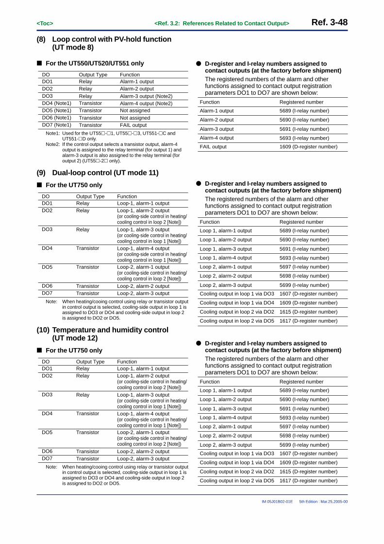
Ref. 3-48<Toc> <Ref. 3.2: References Related to Contact Output>
IM 05J01B02-01E 5th Edition : Mar.25,2005-00
(8) Loop control with PV-hold function(UT mode 8)
■ For the UT550/UT520/UT551 only
DODO1
FunctionAlarm-1 output
DO2 Alarm-2 output Alarm-3 output (Note2) Alarm-4 output (Note2)
Not assigned
DO3DO4 (Note1)DO5 (Note1) Not assigned
Output TypeRelayRelayRelay
TransistorTransistorTransistor
DO6 (Note1)FAIL outputTransistorDO7 (Note1)
Note1: Used for the UT55�-�1, UT55�-�3, UT551-�C andUT551-�D only.
Note2: If the control output selects a transistor output, alarm-4output is assigned to the relay terminal (for output 1) andalarm-3 output is also assigned to the relay terminal (foroutput 2) (UT55�-2� only).
(9) Dual-loop control (UT mode 11)
■ For the UT750 only
DODO1
FunctionLoop-1, alarm-1 output
DO2 Loop-1, alarm-2 output (or cooling-side control in heating/cooling control in loop 2 [Note]) Loop-1, alarm-3 output (or cooling-side control in heating/cooling control in loop 1 [Note]) Loop-1, alarm-4 output (or cooling-side control in heating/cooling control in loop 1 [Note])
Loop-2, alarm-2 output
DO3
DO4
DO5 Loop-2, alarm-1 output (or cooling-side control in heating/cooling control in loop 2 [Note])
Output TypeRelayRelay
Relay
Transistor
Transistor
Transistor
DO6Loop-2, alarm-3 outputTransistorDO7
Note: When heating/cooing control using relay or transistor outputin control output is selected, cooling-side output in loop 1 isassigned to DO3 or DO4 and cooling-side output in loop 2is assigned to DO2 or DO5.
(10) Temperature and humidity control(UT mode 12)
■ For the UT750 only
DODO1
FunctionLoop-1, alarm-1 output
DO2 Loop-1, alarm-2 output (or cooling-side control in heating/cooling control in loop 2 [Note]) Loop-1, alarm-3 output (or cooling-side control in heating/cooling control in loop 1 [Note]) Loop-1, alarm-4 output (or cooling-side control in heating/cooling control in loop 1 [Note])
Loop-2, alarm-2 output
DO3
DO4
DO5 Loop-2, alarm-1 output (or cooling-side control in heating/cooling control in loop 2 [Note])
Output TypeRelayRelay
Relay
Transistor
Transistor
Transistor
DO6Loop-2, alarm-3 outputTransistorDO7
Note: When heating/cooing control using relay or transistor outputin control output is selected, cooling-side output in loop 1 isassigned to DO3 or DO4 and cooling-side output in loop 2is assigned to DO2 or DO5.
● D-register and I-relay numbers assigned tocontact outputs (at the factory before shipment)The registered numbers of the alarm and otherfunctions assigned to contact output registrationparameters DO1 to DO7 are shown below:
Registered number
5689 (I-relay number)
5690 (I-relay number)
5691 (I-relay number)
5693 (I-relay number)
1609 (D-register number)
Function
Alarm-1 output
Alarm-2 output
Alarm-3 output
Alarm-4 output
FAIL output
● D-register and I-relay numbers assigned tocontact outputs (at the factory before shipment)The registered numbers of the alarm and otherfunctions assigned to contact output registrationparameters DO1 to DO7 are shown below:
Registered number
5689 (I-relay number)
5690 (I-relay number)
5691 (I-relay number)
5693 (I-relay number)
1607 (D-register number)
Function
Loop 1, alarm-1 output
Loop 1, alarm-2 output
Loop 1, alarm-3 output
5697 (I-relay number)
5698 (I-relay number)
5699 (I-relay number)
Loop 2, alarm-1 output
Loop 2, alarm-2 output
Loop 2, alarm-3 output
Loop 1, alarm-4 output
Cooling output in loop 1 via DO3
1609 (D-register number)Cooling output in loop 1 via DO4
1615 (D-register number)Cooling output in loop 2 via DO2
1617 (D-register number)Cooling output in loop 2 via DO5

<Toc> <Ref. 3.2: References Related to Contact Output> Ref. 3-49
IM 05J01B02-01E 5th Edition : Mar.25,2005-00
(11) Cascade control with two universal inputs (UT mode 13)
This function is for the UT750 only.The contact output functions in this control mode is the same as for cascade control (UT mode 4) in Item (4). Formore details, refer to Item (4) earlier in this manual.
(12) Loop control with PV switching and two universal inputs (UT mode 14)
This function is for the UT750 only.The contact output functions in this control mode are the same as for the loop control with PV switching (UT mode6) in Item (6). For more details, refer to Item (6) earlier in this manual.
(13) Loop control with PV auto-selector and two universal inputs (UT mode 15)
This function is for the UT750 only.The contact output functions in this control mode are the same as for the loop control with PV auto-selector (UTmode 7) in Item (7). For more details, refer to Item (7) earlier in this manual.
(14) Custom computation control (UT mode 21)
This function is for the UT750 only. The contact output functions are not assigned at the factory before shipment.

Ref. 3-50<Toc> <Ref. 3.2: References Related to Contact Output>
IM 05J01B02-01E 5th Edition : Mar.25,2005-00
<<Ref. 3.2: References Related to Contact Output>>Ref.3.2(2) Changing Contact Output Functions in the UP750 and UP550
Nine contact output terminals (including a common terminal) are provided on both the UP750 and UP550. Theirterminal numbers are 4, 5, 6, 7 (common), 31, 32, 33, 34, and 35 (common), as listed in the table below.
Table 3-2-4 also shows the DO numbers corresponding to each contact output terminal in single-loop UP750 andUP550 controllers. With these DO numbers, functions listed in the table are set at the factory before shipment.(In single-loop controllers, the same contact outputs are set at the factory before shipment.)
For the items set for other than single-loop controllers, refer to pages Ref. 3-49 through Ref. 3-54, to meet yourselected model, later in this manual.
Table 3-2-4 Contact Output Terminals of the UP750 and UP550 (for Single-loop Control) and Their Factory-set Functions
Terminal No.
6
DO No.
DO1
Factory-set Function
PV-event 1 output
5 DO2 PV-event 2 output
Instrument alarm output (or cooling-side control output [Note1])
Time-event 2 output
4 DO3
7 Common terminal (for DO1 to DO3)
34 DO4 Time-event 1 output (or cooling-side control output [Note1])
Output Type
Relay
Relay
Relay
Transistor
Transistor
33 DO5
Time-event 3 output Transistor32 DO6
Time-event 4 output Transistor31 DO7
35 Common terminal (for DO4 to DO7)
Note1: When heating/cooing control using relay or transistor output in control output is selected, cooling-side output is assigned to DO3 orDO4 above.
The UP750 and UP550 enable you to change the contact output functions. These functions can be set with setupparameters DO1 through DO7.
For the procedure of function assignments, follow the steps below:
1) Decide which signal to output from which contact output terminals (see the table above).2) Identify the DO number corresponding to the selected terminal number. For example, if you use terminal
number 6, the corresponding DO number is 1 (DO1).3) Define the type of signal to be output from the terminal. For example, if time-event-1 output is issued with a
relay-contact output using terminal number 6, register the I-relay number (+5000) for the time-event-1output to parameter DO1.The I-relay number for time-event-1 output is 129 as indicated on the I-relay map. For this, registersetpoint: 5129 for parameter DO1.
No.123456
AD1ERRAD2ERRAD3ERR
AD1BO
6566676869
A/M1 129130131132133
TME1TME2TME3
TME4TME5
1 ˜ No. 65 ˜ No. 129 ˜STATUS
No.193194195196197198199
AD1ERRAD2ERRAD3ERR
AD1BOAD2BOAD3BO
257258259260261262263264
A/M1 321322323324325326327328
TME1TME2TME3
TME4TME5TME6
193 ˜ No. 257 ˜ No. 321 ˜ON
I-relay number for time-event-1 output

<Toc> <Ref. 3.2: References Related to Contact Output> Ref. 3-51
IM 05J01B02-01E 5th Edition : Mar.25,2005-00
● To change the contact output functions, use the parameters listed below.Refer to the Default Settings or Parameters section of the appropriate User's Manual to change the parameter values.
• Setup parameters (Contact Output Registration Parameters): DO1 to DO7
UP750UP550
Code
Description
The setting range is indicated by theD-register or I-relay number for a contact output flag + 5000. These numbers depend on the control mode set at the factory. So details on this are described on a mode basis later in this manual.
1106
Setting Range andDefault Settings
D-register No.
DO1 DO1 output flag registration(relay)
1107DO2 DO2 output flag registration(relay)
1108DO3 DO3 output flag registration(relay)
1109DO4 DO4 output flag registration(transistor open-collector)
1110DO5 DO5 output flag registration(transistor open-collector)
1111DO6 DO6 output flag registration(transistor open-collector)
1112DO7 DO7 output flag registration(transistor open-collector)
The contact outputs assigned for individual UP modes in the UP750 and UP550 are as follows:
(1) Single-loop control (UP mode 1)
Contact output
DO1
Function
PV-event-1 output
DO2 PV-event-2 output
Instrument alarm-1 output (or cooling-side output in heating/cooling control [Note1])
Time-event-1 output (or cooling-side output in heating/cooling control [Note1])
Time-event-3 output
DO3
DO4
DO5 Time-event-2 output
Output Type
Relay
Relay
Relay
Transistor
Transistor
Transistor
DO6
Time-event-4 outputTransistorDO7
Note1: When heating/cooing control using relay or transistor output in control output is selected, cooling-side output is assigned to DO3 orDO4 for the UP750.
TIP: If the output type other than a relay (see the table above) is selected for control output, time-event-5 output will be assigned to the relayterminal (for output 1) for the UP550, and time-event-6 output is assigned to the relay terminal (for output 2) for the UP550-2� only.

Ref. 3-52<Toc> <Ref. 3.2: References Related to Contact Output>
IM 05J01B02-01E 5th Edition : Mar.25,2005-00
■ D-register and I-register numbers assigned to contact outputs and extended contact outputs (set atthe factory)
The registered numbers of the alarm and other functions assigned to contact output registration parameters DO1to DO7 are shown below:
Model
Common to UP750 and UP550
Registered number
5705 (I-relay number)
5706 (I-relay number)
5689 (I-relay number)
5129 (I-relay number)
1609 (D-register number)UP750 only
1607 (D-register number)
Function
PV-event-1 output
PV-event-2 output
Instrument alarm-1 output
Time-event-1 output
Cooling-side output inheating/cooling control
Cooling-side output inheating/cooling control
Registered contact output parameters
DO1
DO2
DO3
DO4
DO3
DO4
5130 (I-relay number)
5131 (I-relay number)
5132 (I-relay number)
Time-event-2 output
Time-event-3 output
Time-event-4 output
DO5
DO6
DO7
(2) Cascade, primary-loop control (UP mode 2)
Contact output
DO1
Function
PV-event-1 output
DO2 PV-event-2 output
Instrument alarm-1 output
Time-event-1 output
Time-event-3 output
DO3
DO4
DO5 Time-event-2 output
Output Type
Relay
Relay
Relay
Transistor
Transistor
Transistor
DO6
FAIL outputTransistorDO7
TIP: Time-event-5 output is assigned to the relay terminal (for output 1) for the UP550, and time-event-6 output is assigned to the relayterminal (for output 2) for the UP550-2� only.
■ D-register and I-register numbers assigned to contact outputs and extended contact outputs (set atthe factory)
The registered numbers of the alarm and other functions assigned to contact output registration parameters DO1to DO7 are shown below:
Model
Common to UP750 and UP550
Registered number
5705 (I-relay number)
5706 (I-relay number)
5689 (I-relay number)
5129 (I-relay number)
1609 (D-register number)UP750 only
1607 (D-register number)
Function
PV-event-1 output
PV-event-2 output
Instrument alarm-1 output
Time-event-1 output
Cooling-side output inheating/cooling control
Cooling-side output inheating/cooling control
Registered contact output parameters
DO1
DO2
DO3
DO4
1613 (D-register number)FAIL outputDO7
UP550 only 1611 (D-register number)FAIL outputDO7
DO3
DO4
5130 (I-relay number)
5131 (I-relay number)
Time-event-2 output
Time-event-3 output
DO5
DO6

<Toc> <Ref. 3.2: References Related to Contact Output> Ref. 3-53
IM 05J01B02-01E 5th Edition : Mar.25,2005-00
(3) Cascade control (UP mode 4)
Contact output
DO1
Function
PV-event-1 output
DO2 PV-event-2 output
Instrument alarm-1 output(or cooling-side output in heating/cooling control [Note1])
Time-event-1 output (or cooling-side output in heating/cooling control [Note1])
Time-event-3 output
DO3
DO4
DO5 Time-event-2 output
Output Type
Relay
Relay
Relay
Transistor
Transistor
Transistor
DO6
Time-event-4 outputTransistorDO7
Note1: When heating/cooing control using relay or transistor output in control output is selected, cooling-side output is assigned to DO3 orDO4 for the UP750.
TIP: If the output type other than a relay (see the table above) is selected for control output, time-event-5 output will be assigned to the relayterminal (for output 1) for the UP550, and time-event-6 output will be assigned to the relay terminal (for output 2) for the UP550-2� only.
■ D-register and I-register numbers assigned to contact outputs and extended contact outputs (set atthe factory)
The registered numbers of the alarm and other functions assigned to contact output registration parameters DO1to DO7 are shown below:
Model
Common to UP750 and UP550
Registered number
5705 (I-relay number)
5706 (I-relay number)
5689 (I-relay number)
5129 (I-relay number)
1609 (D-register number)UP750 only
1607 (D-register number)
Function
PV-event-1 output
PV-event-2 output
Instrument alarm-1 output
Time-event-1 output
Cooling-side output inheating/cooling control
Cooling-side output inheating/cooling control
Registered contact output parameters
DO1
DO2
DO3
DO4
DO3
DO4
5130 (I-relay number)
5131 (I-relay number)
5132 (I-relay number)
Time-event-2 output
Time-event-3 output
Time-event-4 output
DO5
DO6
DO7
(4) Loop control with PV switching (UT mode 6)
Contact output
DO1
Function
PV-event-1 output
DO2 PV-event-2 output
Instrument alarm-1 output(or cooling-side output in heating/cooling control [Note1])
Time-event-1 output (or cooling-side output in heating/cooling control [Note1])
Time-event-3 output
DO3
DO4
DO5 Time-event-2 output
Output Type
Relay
Relay
Relay
Transistor
Transistor
Transistor
DO6
Time-event-4 outputTransistorDO7
Note1: When heating/cooing control using relay or transistor output in control output is selected, cooling-side output is assigned to DO3 orDO4 for the UP750.
TIP: If the output type other than a relay (see the table above) is selected for control output, time-event-5 output will be assigned to the relayterminal (for output 1) for the UP550, and time-event-6 output will be assigned to the relay terminal (for output 2) for the UP550-2� only.

Ref. 3-54<Toc> <Ref. 3.2: References Related to Contact Output>
IM 05J01B02-01E 5th Edition : Mar.25,2005-00
■ D-register and I-register numbers assigned to contact outputs and extended contact outputs (set atthe factory)
The registered numbers of the alarm and other functions assigned to contact output registration parameters DO1to DO7 are shown below:
Model
Common to UP750 and UP550
Registered number
5705 (I-relay number)
5706 (I-relay number)
5689 (I-relay number)
5129 (I-relay number)
1609 (D-register number)UP750 only
1607 (D-register number)
Function
PV-event-1 output
PV-event-2 output
Instrument alarm-1 output
Time-event-1 output
Cooling-side output inheating/cooling control
Cooling-side output inheating/cooling control
Registered contact output parameters
DO1
DO2
DO3
DO4
DO3
DO4
5130 (I-relay number)
5131 (I-relay number)
5132 (I-relay number)
Time-event-2 output
Time-event-3 output
Time-event-4 output
DO5
DO6
DO7
(5) Loop control with PV auto-selector (UP mode 7)
Contact output
DO1
Function
PV-event-1 output
DO2 PV-event-2 output
Instrument alarm-1 output(or cooling-side output in heating/cooling control [Note1])
Time-event-1 output (or cooling-side output in heating/cooling control [Note1])
Time-event-3 output
DO3
DO4
DO5 Time-event-2 output
Output Type
Relay
Relay
Relay
Transistor
Transistor
Transistor
DO6
Time-event-4 outputTransistorDO7
Note1: When heating/cooing control using relay or transistor output in control output is selected, cooling-side output is assigned to DO3 orDO4 for the UP750.
TIP: If the output type other than a relay (see the table above) is selected for control output, time-event-5 output will be assigned to the relayterminal (for output 1) for the UP550, and time-event-6 output will be assigned to the relay terminal (for output 2) for the UP550-2� only.
■ D-register and I-register numbers assigned to contact outputs and extended contact outputs (set atthe factory)
The registered numbers of the alarm and other functions assigned to contact output registration parameters DO1to DO7 are shown below:
Model
Common to UP750 and UP550
Registered number
5705 (I-relay number)
5706 (I-relay number)
5689 (I-relay number)
5129 (I-relay number)
1609 (D-register number)UP750 only
1607 (D-register number)
Function
PV-event-1 output
PV-event-2 output
Instrument alarm-1 output
Time-event-1 output
Cooling-side output inheating/cooling control
Cooling-side output inheating/cooling control
Registered contact output parameters
DO1
DO2
DO3
DO4
DO3
DO4
5130 (I-relay number)
5131 (I-relay number)
5132 (I-relay number)
Time-event-2 output
Time-event-3 output
Time-event-4 output
DO5
DO6
DO7

<Toc> <Ref. 3.2: References Related to Contact Output> Ref. 3-55
IM 05J01B02-01E 5th Edition : Mar.25,2005-00
(6) Dual-loop control (UP mode 11)This function is for the UP750 only.
Contact output
DO1
Function
PV-event-1 output
DO2 PV-event-2 output(or cooling-side output in heating/cooling control in loop 2 [Note])
Instrument alarm-1 output(or cooling-side output in heating/cooling control in loop 1 [Note])
Time-event-1 output (or cooling-side output in heating/cooling control in loop 1 [Note])
Time-event-3 output
DO3
DO4
DO5 Time-event-2 output(or cooling-side output in heating/cooling control in loop 2 [Note])
Output Type
Relay
Relay
Relay
Transistor
Transistor
Transistor
DO6
Time-event-4 outputTransistorDO7
Note: When heating/cooing control using relay or transistor output in control output is selected, cooling-side output in loop 1 is assigned toDO3 or DO4, and cooling-side output in loop 2 is assigned to DO2 or DO5.
■ D-register and I-register numbers assigned to contact outputs and extended contact outputs (set atthe factory)
The registered numbers of the alarm and other functions assigned to contact output registration parameters DO1to DO7, R151 to R158, and R251 to R258 are shown below:
Registered number
5705 (I-relay number)
5706 (I-relay number)
1615 (D-register number)
5689 (I-relay number)
5132 (I-relay number)
5131 (I-relay number)
Function
PV-event-1 output
PV-event-2 output
Cooling-side control output in loop 2
Instrument alarm-1 output
Time-event-4 output
Time-event-3 output
Contact output registration parameter
DO1
DO2
DO7
DO6
DO31607 (D-register number)
5129 (I-relay number)
1609 (D-register number)
Cooling-side control output in loop 1
Time-event-1 output
Cooling-side control output in loop 1DO4
5130 (I-relay number)
1617 (D-register number)
Time-event-2 output
Cooling-side control output in loop 2DO5
(7) Temperature and humidity control (UP mode 12)This function is for the UP750 only.
Contact output
DO1
Function
PV-event-1 output
DO2 PV-event-2 output(or cooling-side output in heating/cooling control in loop 2 [Note])
Instrument alarm-1 output(or cooling-side output in heating/cooling control in loop 1 [Note])
Time-event-1 output (or cooling-side output in heating/cooling control in loop 1 [Note])
Time-event-3 output
DO3
DO4
DO5 Time-event-2 output(or cooling-side output in heating/cooling control in loop 2 [Note])
Output Type
Relay
Relay
Relay
Transistor
Transistor
Transistor
DO6
Time-event-4 outputTransistorDO7
Note: When heating/cooing control using relay or transistor output in control output is selected, cooling-side output in loop 1 is assigned toDO3 or DO4, and cooling-side output in loop 2 is assigned to DO2 or DO5.

Ref. 3-56<Toc> <Ref. 3.2: References Related to Contact Output>
IM 05J01B02-01E 5th Edition : Mar.25,2005-00
■ D-register and I-register numbers assigned to contact outputs and extended contact outputs (set atthe factory)
The registered numbers of the alarm and other functions assigned to contact output registration parameters DO1to DO7, R151 to R158, and R251 to R258 are shown below:
Registered number
5705 (I-relay number)
5706 (I-relay number)
1615 (D-register number)
5689 (I-relay number)
5132 (I-relay number)
5131 (I-relay number)
Function
PV-event-1 output
PV-event-2 output
Cooling-side control output in loop 2
Instrument alarm-1 output
Time-event-4 output
Time-event-3 output
Contact output registration parameter
DO1
DO2
DO7
DO6
DO31607 (D-register number)
5129 (I-relay number)
1609 (D-register number)
Cooling-side control output in loop 1
Time-event-1 output
Cooling-side control output in loop 1DO4
5130 (I-relay number)
1617 (D-register number)
Time-event-2 output
Cooling-side control output in loop 2DO5
(8) Cascade control with two universal inputs (UP mode 13)
This function is for the UP750 only.The contact output functions in this control mode is the same as for cascade control (UP mode 4) in Item (3). Formore details, refer to Item (3) earlier in this manual.
(9) Loop control with PV switching and two universal inputs (UP mode 14)
This function is for the UP750 only.The contact output functions in this control mode is the same as for the loop control with PV switching (UP mode6) in Item (4). For more details, refer to Item (4) earlier in this manual.
(10) Loop control with PV auto-selector and two universal inputs (UP mode 15)
This function is for the UP750 only.The contact output functions in this control mode is the same as for the loop control with PV auto-selector (UPmode 7) in Item (5). For more details, refer to Item (5) earlier in this manual.
(11) Custom computation control (UP mode 21)
This function is for the UP750 only. The contact output functions are not assigned at the factory before shipment.

<Toc> <Ref. 3.2: References Related to Contact Output> Ref. 3-57
IM 05J01B02-01E 5th Edition : Mar.25,2005-00
<<Ref. 3.2: References Related to Contact Output>>Ref.3.2(3) Using the I/O Expansion Module with UT750 and UP750
Nine contact output terminals (including a common terminal) are provided on both UT750 and UP550.Their terminal numbers are 4, 5, 6, 7 (common), 31, 32, 33, 34, and 35 (common).
If the number of the contact output terminals is not enough, use contact I/O expansion modules (Note1) enablingyou to use up to 23-point contact outputs. Up to two I/O expansion modules can be connected. One of theseincorporates eight contact inputs and outputs. If you use two modules, 16-point plus 7-point contact outputs(excluding common terminals 7 and 35) are available.
Note1: Requires Yokogawa’s optional add-on module for the FA20 compact program controller.
INPUT 24V DC 5mA
OUTPUT
INPUT 24V DC 5mA
OUTPUT
OUTPUT
SUPPLY
A B SHIELD24V DC 0.1A OUTPUT 240V AC 2A/24V DC 2A • BUS
INPUT
Eight-pointinputs
Eight-pointoutputs
µFA20 Expansion Module1
Eight-pointinputs
Eight-pointoutputs
µFA2 Expansion Module2
µ-bus communications 15meters maximum
INPUT
POWERRUN
POWERRUN
123
4
OUTPUT
SUPPLY
A B SHIELD24V DC 0.1A OUTPUT 240V AC 2A/24V DC 2A • BUS
POWERRUN
123
4
1 2 3 4
5 6 7 8
9 10 11 12
51 52 53 54
55 56 57 58
1 2 3 4
5 6 7 8
9 10 11 12
51 52 53 54
55 56 57 58
Fig. 3-2-1 I/O Expansion
The following four types of I/O expansion modules are available depending on the supply voltage and outputtypes. Select the one that meets your needs.
P2ER1-20J
Supply voltage Model
100 to 240 V AC
Output type
Relay
P2ET1-20J 100 to 240 V AC Transistor
P2ER6-20J 24 V DC Relay
P2ET6-20J 24 V DC Transistor
Uses of the I/O expansion module’s contact output terminals vary between the UT750 Digital Indicating Controllerand the UP750 Program Controller.The following describes the applications where the UT750 is used and then where the UP750 is used.Select and refer to the one appropriate for your selected model.
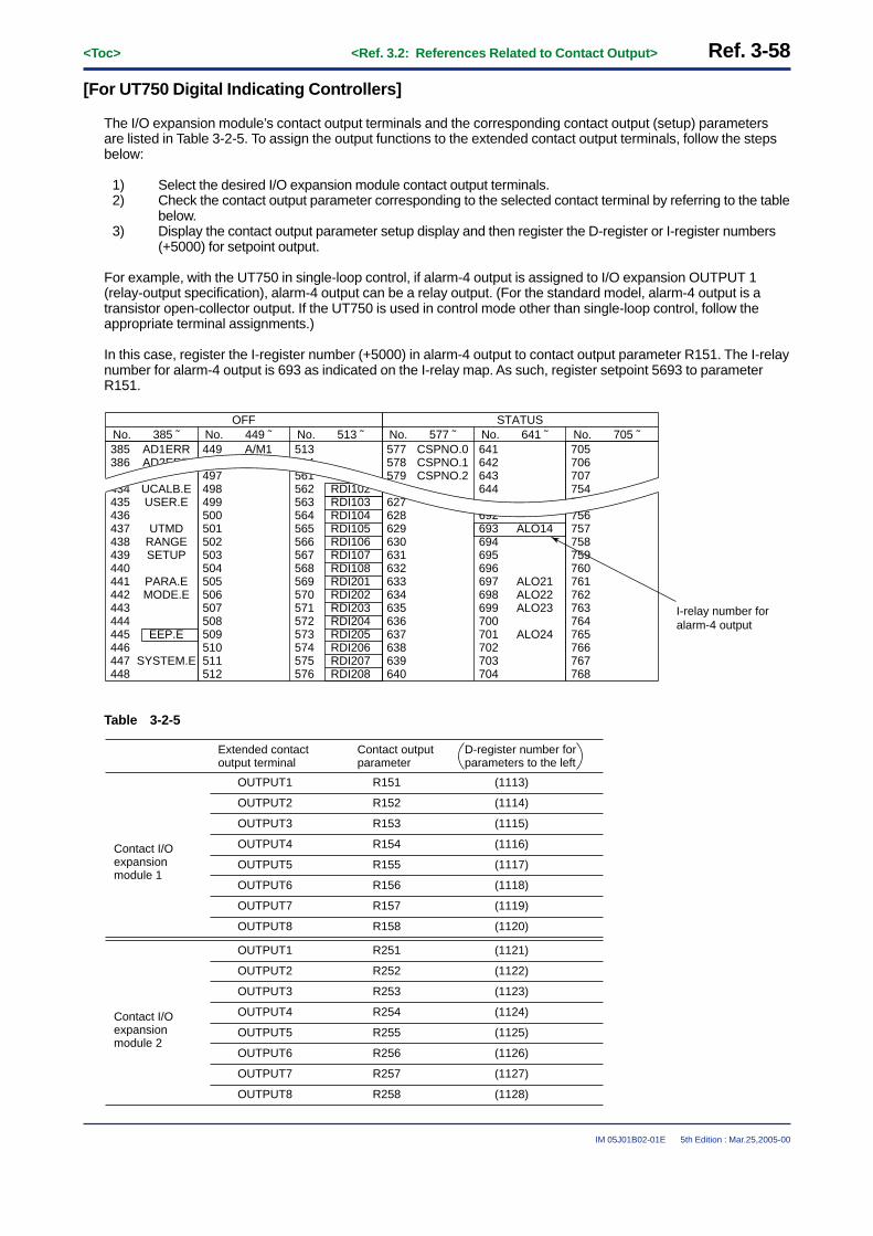
Ref. 3-58<Toc> <Ref. 3.2: References Related to Contact Output>
IM 05J01B02-01E 5th Edition : Mar.25,2005-00
[For UT750 Digital Indicating Controllers]
The I/O expansion module’s contact output terminals and the corresponding contact output (setup) parametersare listed in Table 3-2-5. To assign the output functions to the extended contact output terminals, follow the stepsbelow:
1) Select the desired I/O expansion module contact output terminals.2) Check the contact output parameter corresponding to the selected contact terminal by referring to the table
below.3) Display the contact output parameter setup display and then register the D-register or I-register numbers
(+5000) for setpoint output.
For example, with the UT750 in single-loop control, if alarm-4 output is assigned to I/O expansion OUTPUT 1(relay-output specification), alarm-4 output can be a relay output. (For the standard model, alarm-4 output is atransistor open-collector output. If the UT750 is used in control mode other than single-loop control, follow theappropriate terminal assignments.)
In this case, register the I-register number (+5000) in alarm-4 output to contact output parameter R151. The I-relaynumber for alarm-4 output is 693 as indicated on the I-relay map. As such, register setpoint 5693 to parameterR151.
No.385386
434435436437438439440441442443444445446447448
AD1ERRAD2ERR
UCALB.EUSER.E
UTMDRANGESETUP
PARA.EMODE.E
EEP.E
SYSTEM.E
449
497498499500501502503504505506507508509510511512
A/M1 513514561562563564565566567568569570571572573574575576
RDI102RDI103RDI104RDI105RDI106RDI107RDI108RDI201RDI202RDI203RDI204RDI205RDI206RDI207RDI208
385 ˜ No. 449 ˜ No. 513 ˜OFF
No.577578579
627628629630631632633634635636637638639640
CSPNO.0CSPNO.1CSPNO.2
641642643644
692693694695696697698699700701702703704
ALO14
ALO21ALO22ALO23
ALO24
705706707754755756757758759760761762763764765766767768
577 ˜ No. 641 ˜ No. 705 ˜STATUS
I-relay number for alarm-4 output
Table 3-2-5
OUTPUT1
Contact output parameter
Extended contact output terminal
Contact I/O expansion module 1
Contact I/O expansion module 2
R151
D-register number for parameters to the left
(1113)
OUTPUT2 R152 (1114)
OUTPUT3 R153 (1115)
OUTPUT4 R154 (1116)
OUTPUT5 R155 (1117)
OUTPUT6 R156 (1118)
OUTPUT7 R157 (1119)
OUTPUT8 R158 (1120)
OUTPUT1 R251 (1121)
OUTPUT2 R252 (1122)
OUTPUT3 R253 (1123)
OUTPUT4 R254 (1124)
OUTPUT5 R255 (1125)
OUTPUT6 R256 (1126)
OUTPUT7 R257 (1127)
OUTPUT8 R258 (1128)

<Toc> <Ref. 3.2: References Related to Contact Output> Ref. 3-59
IM 05J01B02-01E 5th Edition : Mar.25,2005-00
● The following parameters are used for extending the contact output functions.To change the parameter values, consult the Default Settings or Parameters section of the appropriate user’s manual.
• Setup parameters (Contact Output Registration Parameters): R151 to R258
UT750
Code
Description Setting Range
11130 (with no functions)
Default D-register Number
R151 R151 output flag registration
↓↓ Setting range: D-register or I-register number + 5000↓↓ For D-register numbers for parameters R152 to R257, see Table 3-2-5.↓↓
11280 (with no functions)R258 R258 output flag registration
[For the UP750 Program Controllers]
For the UP750, commonly used contact functions are assigned in advance to the I/O expansion module’s contactoutput terminals.The pre-assigned contact output features are listed in Table 3-2-6 below.
■ Extended contact output (for UP750 only)
When the contact I/O expansion module is connected to the UP750, PV-event and time-event outputs are outputto the extended contact outputs (R151 to R158, and R251 to R258).
Table 3-2-6
Contact Output(Parameters)
R151 (Note2)
Functions
PV-event-3 output
R152 (Note2) PV-event-4 output
Time-event-5 output
Time-event-6 output
Time-event-8 output
R153 (Note2)
R154 (Note2)
R155 (Note2) Time-event-7 output
Output type(Note1)
Relay/O.C.
Relay/O.C.
Relay/O.C.
Relay/O.C.
Relay/O.C.
Relay/O.C.
R156 (Note2)
Time-event-9 output
Default Settings(Set at the factory)
5707 (I-relay number)
5709 (I-relay number)
5134 (I-relay number)
5135 (I-relay number)
5138 (I-relay number)
5137 (I-relay number)
5145 (I-relay number)Relay/O.C.R157 (Note2)
Time-event-10 output 5146 (I-relay number)Relay/O.C.R158 (Note2)
R251 (Note3) PV-event-5 output
R252 (Note3) PV-event-6 output
Time-event-11 output
Time-event-12 output
Time-event-14 output
R253 (Note3)
R254 (Note3)
R255 (Note3) Time-event-13 output
Relay/O.C.
Relay/O.C.
Relay/O.C.
Relay/O.C.
Relay/O.C.
Relay/O.C.
R256 (Note3)
Time-event-15 output
5710 (I-relay number)
5711 (I-relay number)
5147 (I-relay number)
5149 (I-relay number)
5151 (I-relay number)
5150 (I-relay number)
5153 (I-relay number)Relay/O.C.R257 (Note3)
Time-event-16 output 5154 (I-relay number)Relay/O.C.R258 (Note3)
Note1: “O.C.” in the table below indicates the open collector output (transistor output)Note2: Extended contact output of contact I/O expansion module 1 connected to the UP750.Note3: Extended contact output of contact I/O expansion module 2 connected to the UP750.

Ref. 3-60<Toc> <Ref. 3.2: References Related to Contact Output>
IM 05J01B02-01E 5th Edition : Mar.25,2005-00
These functions can be used simply by connecting the I/O expansion module to the UP750 via µ-bus communica-tions. In addition, part or all of the I/O expansion module terminal functions can also be changed. To do this, followthe steps below:The I/O expansion module contact output terminals and the corresponding contact output parameter (setupparameter) numbers are shown in Table 3-2-7.
1) Select the desired I/O expansion module contact output terminals.2) Check the contact output parameter corresponding to the selected contact terminal by referring to the table
below.3) Display the contact output parameter setup display and then register the D-register or I-register numbers
(+5000) for setpoint output.
For example, with the UP750 in single-loop control, if time-event 1 is assigned to I/O expansion OUTPUT 1 (relay-output specification), time-event 1 can be a relay output. For the standard model, time-event 1 is transistor open-collector output. If the UP750 is used in a control mode other than single-loop control, follow the appropriateterminal assignments.
In this case, register the I-relay number (+5000) in time-event 1 to contact output parameter R151. The I-relaynumber for time-event 1 is 129 as indicated on the I-relay map. As such, register setpoint 5129 to parameter R151.
No.123456
AD1ERRAD2ERRAD3ERR
AD1BO
6566676869
A/M1 129130131132133
TME1TME2TME3
TME4TME5
1 ˜ No. 65 ˜ No. 129 ˜STATUS
No.193194195196197198199
AD1ERRAD2ERRAD3ERR
AD1BOAD2BOAD3BO
257258259260261262263264
A/M1 321322323324325326327328
TME1TME2TME3
TME4TME5TME6
193 ˜ No. 257 ˜ No. 321 ˜ON
I-relay number for time-event-1 output
Table 3-2-7
OUTPUT1
Contact output parameter
Extended contact output terminal
Contact I/O expansion module 1
Contact I/O expansion module 2
R151
D-register number for parameters to the left
1113
OUTPUT2 R152 1114
OUTPUT3 R153 1115
OUTPUT4 R154 1116
OUTPUT5 R155 1117
OUTPUT6 R156 1118
OUTPUT7 R157 1119
OUTPUT8 R158 1120
OUTPUT1 R251 1121
OUTPUT2 R252 1122
OUTPUT3 R253 1123
OUTPUT4 R254 1124
OUTPUT5 R255 1125
OUTPUT6 R256 1126
OUTPUT7 R257 1127
OUTPUT8 R258 1128

<Toc> <Ref. 3.2: References Related to Contact Output> Ref. 3-61
IM 05J01B02-01E 5th Edition : Mar.25,2005-00
● The following parameters are used for extending the contact output functions.To change the parameter values, consult the Default Settings or Parameters section of the appropriate user’s manual.
• Setup parameters (Contact Output Registration Parameters): R151 to R258
UP750
Code
Description Setting Range
11130 (with no functions)
Default D-register Number
R151 R151 output flag registration
↓↓ Setting range: D-register or I-register number + 5000↓↓ For D-register numbers for parameters R152 to R257, see Table 3-2-5.↓↓
11280 (with no functions)R258 R258 output flag registration

Ref. 3-62<Toc> <Ref. 3.3: References Related to Alarms>
IM 05J01B02-01E 5th Edition : Mar.25,2005-00
Ref.3.3: References Related to Alarms
IMPORTANT: Applicable models of this sectionUP750 UP550 UP35� UT750 UT5�� UT4�0 UT3��
None
For UP controllers, see Ref. 3.4: References on Events.
None None UT750-�� UT5��-�� UT4�0-�� UT3��-��
Note: Some of the functions below are not available on certain models.For more information, see those sections.
This section contains reference information on the following aspects of alarms.Refer to this information and change parameters only if necessary.
(1) Setting alarm trigger conditions(2) Setting alarm hysteresis ON/OFF range(3) Using the alarm timer (Control stable signal event)(4) Using the sensor ground alarm(5) Using the heater burnout alarm (UT350, UT320, UT351 and UT321 only)

<Toc> <Ref. 3.3: References Related to Alarms> Ref. 3-63
IM 05J01B02-01E 5th Edition : Mar.25,2005-00
<<Ref. 3.3: Reference Related to Alarms>>Ref.3.3(1) Setting Alarm Trigger Conditions
Alarm trigger conditions can be set with the UT750, UT550, UT520, UT551, UT450 and UT420.
There are 3 alarm trigger conditions (alarm mode). (Note1)Alarm mode is selected with the “AMD” parameter as indicted in the table below.
• Always active← ( Factory-set default )• Not active when in Stop mode• Not active when in Stop mode or Manual operation
Note1: With the UT550, UT551 and UT520, alarm triggers can be selected from the following 3 conditions in addition to those above. Theseconditions are used as dual-loop control with a maximum 8 alarms.
• All 8 alarms always active• All 8 alarms not active when in Stop mode• All 8 alarms not active when in Stop mode or Manual operation
● The following parameters are used.Change parameters as explained in the User’s Manuals Initial Settings and Parameter Map.
• Setup parameters (Alarm-related Parameters) : AMDUT750
Code
Description Setting range
0: Always active1: Not active when in Stop mode2: Not active when in Stop mode or Manual operation
3: All 8 alarms always active4: All 8 alarms not active when in Stop mode5: All 8 alarms not active when in Stop mode or Manual operation
923 (loop-1)
963 (loop-2)**secondary loop
0
Default D-registerNo.
UT5��UT4�0
Code
AMD Alarm mode
The followings (Setpoint: 3 to 5) can be set with only UT5��.However, those can not be set in Cascade control mode.
(AMD)
Note1: With the UT5��, displays the parameters (AL1 to AL4) for loop-2 when the set value 3, 4 or 5 is registered in “AMD”.The 5th to 8th alarms can be set to these parameters (AL1 to AL4) for loop-2. (However, those can not be set in Cascade controlmode.)
A parts of the UT750 parameter map is shown below.Refer and use the map to find the path to the setting display for a particular parameter.

Ref. 3-64<Toc> <Ref. 3.3: References Related to Alarms>
IM 05J01B02-01E 5th Edition : Mar.25,2005-00
Main menu
Sub menu
LOOP1
SP ALM CTL
SETSET SET
OK
SET DISP
UT750 Setup Parameters Map
Password
TMU
SPTRMS
CONF UTMD
MODOPR
RDVRHY
AL4AL3AL2AL1
HY3HY2HY1
AMD
HY4
DY3DY2DY1
DY4
LOOP2 CMLP
DISP
Operating Parametersetting display
Same asloop-1
PVT
SPHSPL
“AMD”
Referring to the Parameter map,
display the setup parameter
main menu [LOOP1] .
Then, display the submenu [ALM].
And press the key time and again
to display the parameter “AMD”.
Adjust the parameter value using the
/ keys, then press the key to
register it.
SET/ENT
SET/ENT

<Toc> <Ref. 3.3: References Related to Alarms> Ref. 3-65
IM 05J01B02-01E 5th Edition : Mar.25,2005-00
<<Ref. 3.3: Reference Related to Alarms>>Ref.3.3(2) Setting Alarm hysteresis ON/OFF range
Alarm hysteresis ON/OFF range can be set with the UT750, UT550, UT520, UT551, UT450, UT420, UT35� andUT32�.This function differs, as follows, according to model. Use it as specified for your model.
(1) With the UT35�, UT32� and UT420, alarm 1 hysteresis (HY1) to alarm 3 hysteresis (HY3) correspond toalarm 1 (AL1) to alarm 3 (AL3), respectively.
(2) With the UT750, UT550, UT520, UT551 and UT450, alarm 1 hysteresis (HY1) to alarm 4 hysteresis (HY4)correspond to alarm 1 (AL1) to alarm 4 (AL4), respectively.
(3) The UT550, UT520 and UT551 add alarms 5 to 8 to those above. Alarm 5 hysteresis (uses HY1 of thesecondary loop) to alarm 8 hysteresis (uses HY4 of the secondary loop) correspond to alarm 5 (uses AL1of the secondary loop) to alarm 8 (uses AL4 of the secondary loop).
Note: With the UT550, UT520 and UT551, primary loop alarms 5 to 8 are set in the “AL1” to “AL4” parameters of the secondary loop. SeeRef. 3-3: (1) Setting Alarm Trigger Conditions.
The alarm hysteresis (ON/OFF) bands for individual alarms can be set within the 0.0% to 100.0% range of PVinput range span.
The following is an example of how to set the Alarm-1 hysteresis (HY1) when alarm1 is set as a PV high limitalarm (alarm type code=1)
In Fig. 3-3-1 and 3-3-2, “open” and “close” refer to the relay contact status.In example below, the instrument range (RL to RH) is set as 0 to1000� C.In Fig. 3-3-1, HY1 is set at 5 � C (0.5% of instrument range span).
Closed (ON)
Open
Time
Alarm-1 setpoint = 100�C (example)
Closed (ON)
Open
Time
Fig. 3-3-2Fig. 3-3-1
Alarm-1 setpoint = 100�C (example)
HY1 : 15�C (example)HY1 : 5�C (example)
PV PVAlarm ON
OFF
ON
OFF
ON
OFF
Alarm ON
OFF
If the alarm turns on and off too often, set hysteresis band wider to reduce the excessive number of on/off actions.In Fig. 3-3-2, the on/off action of the alarm is moderate compared to that in Fig. 3-3-1 because of the wider HY1hysteresis band.

Ref. 3-66<Toc> <Ref. 3.3: References Related to Alarms>
IM 05J01B02-01E 5th Edition : Mar.25,2005-00
● The following parameters are used.Change parameters as explained in the User’s Manuals Initial Settings and Parameter Map.
• Setup parameters (Alarm related Parameters) : HY1, HY2, HY3, HY4 (Note1)
UT750
Code
Description Setting range
0.0 to 100.0% ofPV input range span
919 (loop-1)959 (loop-2)*
0.5% ofPV input range span
Default D-registerNo.
UT5��UT4�0UT3��Code
HY1 Alarm-1 hysteresis
(HY1)
HY2 Alarm-2 hysteresis 0.0 to 100.0% ofPV input range span
0.5% ofPV input range span
920 (loop-1)960 (loop-2)*
921 (loop-1)961 (loop-2)*
922 (loop-1)962 (loop-2)*
0.5% ofPV input range span
0.5% ofPV input range span
0.0 to 100.0% ofPV input range span
0.0 to 100.0% ofPV input range span
Alarm-3 hysteresis
Alarm-4 hysteresis
HY3
HY4
(HY2)
(HY3)
(HY4) (Note1)
Note1: UT3�� and UT420 has no Alarm-4 hysteresis.Note2: UT3��and UT4�0 has no Loop-2 (* secondary loop).
A parts of the UT750 parameter map is shown below.Refer and use the map to find the path to the setting display for a particular parameter.
LOOP1
SP ALM CTL
SET
OK
SET DISP
UT750 Setup Parameters Map
TMUPVTSPTRMS
CONF UTMD
MODOPR
AL4AL3AL2AL1
HY3HY2HY1
AMD
HY4
LOOP2 CMLP
DISP
RDVRHYSPH
SPL
SETSET
DY3DY2DY1
DY4
Main menu
Sub menu
Password Operating Parametersetting display
Same asloop-1
“HY1”“HY2”“HY3”“HY4”
Referring to the Parameter map,
display the setup parameter
main menu [LOOP1] .
Then, display the submenu [ALM].
And press the key time and
again to display the parameter “HY1”.
Adjust the parameter value using the
/ keys, then press the key
to register it.
SET/ENT
SET/ENT

<Toc> <Ref. 3.3: References Related to Alarms> Ref. 3-67
IM 05J01B02-01E 5th Edition : Mar.25,2005-00
<<Ref. 3.3: Reference Related to Alarms>>Ref.3.3(3) Using the alarm timer (Control stable signal event)
Alarm timer function can be used with the UT750, UT550, UT520, UT551, UT450 and UT420.
The alarm timer notifies the operator when PV is stable.The timer starts counting the moment that PV attains the target setpoint (or is within that hysteresis range).Then, when the set time elapses, alarm 1 (relay) output turns ON. To use the alarm timer, the “AL1” setup param-eter that determines the type of alarm is set to “21” to “24”. Timer time is set with the “1.A1” operating parameter.Timer output turns OFF in the following cases.
• When power is turned OFF• When operation stops• When target setpoint No. is changed (to any number other than 1)• During remote control• When timer time is set to “OFF”
■ The alarm timer can only be set for alarm 1. It cannot be set for alarms 2 to 4.
Example of the alarm timer operation
(1) The ON/OFF operation in upward detection is shown below (in Fig. 3-3-3).
Blink
SPAlarm-HY
ONOFFAlarm output
Out On
Timer setting(changeable)
Remaining time(unchangeable) (unchangeable)
Timer setting(changeable)
Timer time can be displayed and / or set in the Operating display.
Alarm lamp state
Operating Display
Set time period
Time up
Reset
Out
Control start
PV
Fig. 3-3-3 Upward Detection
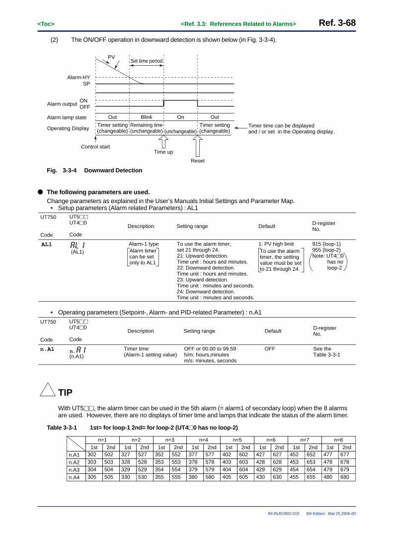
Ref. 3-68<Toc> <Ref. 3.3: References Related to Alarms>
IM 05J01B02-01E 5th Edition : Mar.25,2005-00
(2) The ON/OFF operation in downward detection is shown below (in Fig. 3-3-4).
BlinkOut On Out
Timer setting(changeable)
Remaining time(unchangeable) (unchangeable)
Timer setting(changeable)
Set time period
Time up
Reset
SPAlarm-HY
ONOFFAlarm output
Alarm lamp state
Operating Display Timer time can be displayed and / or set in the Operating display.
PV
Control start
Fig. 3-3-4 Downward Detection
● The following parameters are used.Change parameters as explained in the User’s Manuals Initial Settings and Parameter Map.
• Setup parameters (Alarm related Parameters) : AL1UT750
Code
Description Setting range
To use the alarm timer, set 21 through 24.21: Upward detection. Time unit : hours and minutes.22: Downward detection. Time unit : hours and minutes.23: Upward detection. Time unit : minutes and seconds.24: Downward detection. Time unit : minutes and seconds.
915 (loop-1)955 (loop-2)Note: UT4�0
has no loop-2
1: PV high limit
Default D-registerNo.
UT5��UT4�0
Code
AL1 Alarm-1 type
(AL1) Alarm timercan be setonly to AL1
To use the alarmtimer, the settingvalue must be setto 21 through 24.
• Operating parameters (Setpoint-, Alarm- and PID-related Parameter) : n.A1
UT750
Code
Description Setting range
OFF or 00.00 to 99.59h/m: hours,minutes m/s: minutes, seconds
See theTable 3-3-1
OFF
Default D-registerNo.
UT5��UT4�0
Code
n.A1 Timer time(Alarm-1 setting value)(n.A1)
n.
TIP
With UT5��, the alarm timer can be used in the 5th alarm (= alarm1 of secondary loop) when the 8 alarmsare used. However, there are no displays of timer time and lamps that indicate the status of the alarm timer.
Table 3-3-1 1st= for loop-1 2nd= for loop-2 (UT4�0 has no loop-2)
n=11st 2nd
n=21st 2nd
n=31st 2nd
n=41st 2nd
n=51st 2nd
n=61st 2nd
n=71st 2nd
n=81st 2nd
302303
n.A1n.A2
502503
327328
352353
552553
377378
577578
427428
627628
452453
652653
477478
677678
402403
602603
304305
n.A3n.A4
504505
329330
527528529530
354355
554555
379380
579580
429430
629630
454455
654655
479480
679680
404405
604605

<Toc> <Ref. 3.3: References Related to Alarms> Ref. 3-69
IM 05J01B02-01E 5th Edition : Mar.25,2005-00
■ Setting the Required Parameters
To use the alarm timer , 2 parameters must be set at the same time.These parameters are setup parameter “AL1” and operating parameter “n.A1”.Carry out the parameter setting operation shown below.
Here we explain how to display the parameter setting display and to change the parameter values. Beforecarrying out these operations be sure to refer to the User’s Manuals Initial Settings and Parameter Map of thecontroller.The parameter map is very helpful in finding the path to the setting display for a particular parameter.
1: Referring to the User’s Manual above,display the setup parameter main menu[LOOP1] .Then, display the submenu [ALM].
2 : Press the SET/ENT key one time to display theparameter “AL1”.Set the parameter value to 21,22,23 or 24using the / keys, then pressthe SET/ENT key to register it.For example, register “21” when you wantto select the alarm type of “Upward detec-tion. Time unit : hours and minutes”.
3 : After the above operation, pressing theSET/ENT key for at least 3 seconds to go back
to the operating display.
4: Then, press the SET/ENT key for at least 3seconds again to display the operatingparameter main menu [MODE].Press key one time to display mainmenu [LP1].Then, display the submenu [1.PID].
5: Press the SET/ENT key 2 times to display theparameter “1.A1”.The alarm timer time can be set to thisparameter. • Adjust the time value using the
/ keys, then press the SET/ENT key to register it.
(The unit of time has been set when theparameter “AL1” value registered.)
LOOP1
SP ALM CTL
SET
OK
SET DISP
TMUPVTSPTRMS
CONF UTMD
MODOPR
AL4AL3AL2AL1
HY3HY2HY1
AMD
LOOP2 CMLP
DISP
RDVRHYSPH
SPL
SETSET
UT550 Setup parameter Map
Main menu
Sub menu
Password Operation parameters
Same asLOOP1
“AL1”
SET3S
Operating
+
FLBSSCAT
RTDNRUPR
RFLRBS
ORHORB
ORL
LP1 LP2 USR PY2 STUP
PAR 1.PID 7.PID 8.PID
Same asLP1
SET
SET
SET
1.A31.A21.A11.SP
1.I1.P1.A4
1.OH1.D
1.MR1.OL
1.H
1.Pc1.DR
1.Ic
1.Hc1.Dc
1.DB
1.PO1.RP
1.Oc
SET
7.A37.A27.A1
7.I7.P7.A4
7.OH7.D
7.MR7.OL
7.H
7.Pc7.DR
7.Ic
7.Hc7.Dc
7.DB
7.PORHY
7.Oc
SET
8.A38.A28.A18.SP
8.I8.P8.A4
8.OH8.D
8.MR8.OL
8.H
8.Pc8.DR
8.Ic
8.Hc8.Dc
8.DB
8.PORDV
8.Oc
SET
MODE
MOD(C.A.M)
SPN
MOD(R/L)
orSET3S
+
7.SP
UT550/UT520 Operating parameter Map
PY1
Main menu
Sub menu
“1.A1”

Ref. 3-70<Toc> <Ref. 3.3: References Related to Alarms>
IM 05J01B02-01E 5th Edition : Mar.25,2005-00
<<Ref. 3.3: Reference Related to Alarms>>Ref.3.3(4) Using the sensor ground alarm
The sensor ground alarm can be used with theUT750,UT550,UT520, UT551, UT450,UT420,UT35� and UT32�.However, it can not be used with position proportional type controllers (UT750-1� and UT55�-1�).
This function is not active in the following case.• During manual operation mode.• When operation stops• During ON/OFF control mode• During auto-tuning• During cascade control mode
This function differs slightly, as follows, according to model.Use it as specified for your model.
When the controller-indicated PV and actual temperature of the furnace differ, sensor loss can be evaluated fromthe change in output.For example, when the temperature inside the furnace is 110°C despite the fact that the controller indicates as100°C. In this particular case, output is higher than that at a 100°C PV. This can be detected by the sensor groundalarm. In using this function, the user must keep data on the normal output range (i.e.: how much output there is ata PV of 100°C).
Furnace
Product
SSR
PV from sensor; 100°C
MV output
Actual temperature: 110°C The MV output is not the output
at PV 100°C but the output at the actual 110°C.
100°C
Fig. 3-3-5
Sensor loss detection works as follows. Sensor loss is detected and an alarm is output when the moving averageof the control output (ON/OFF rate) drifts outside the set high limit (operating parameter “ORH”) and low limit(operating parameter “ORL”). This is done even if control is stable and PV stays within a constant range of thetarget setpoint. The sensor ground alarm trigger is shown in Fig. 3-3-2.The moving average is computed as follows. Computation starts after PV is within the ON/OFF rate detectionband.Note: This moving average is the ON/OFF rate (OR).
With the UT35� and UT32�, the ON/OFF rate (OR) value can be displayed for your checking. When needed,check it on the “OR” parameter display. Display capabilities are not provided on other models.The displayed ON/OFF rate is the moving average taken from 5 control output cycles. When this moving averagevalue drifts outside of the set ORL - ORH range, the sensor ground alarm is output.Note: This moving average is the ON/OFF rate (OR).
Moving average = = ON/OFF rate (OR)5
OUTn + OUTn-1 + OUTn-2 + OUTn-3 + OUTn-4
OUTn is the current output.
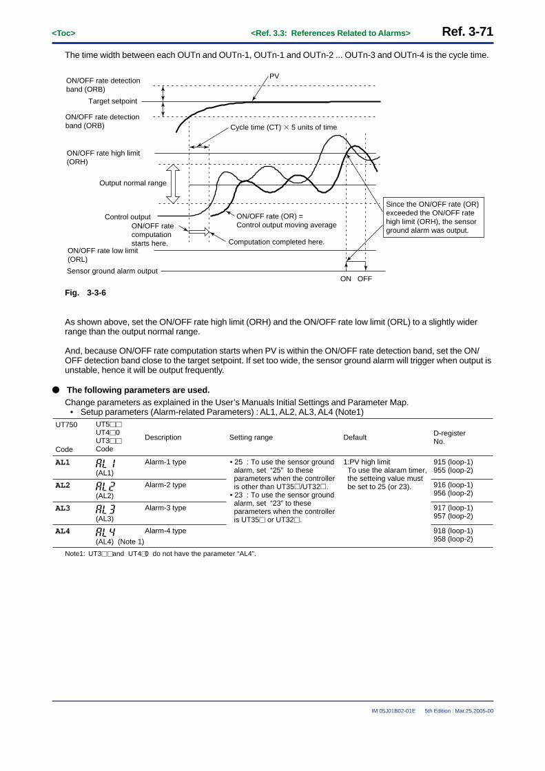
<Toc> <Ref. 3.3: References Related to Alarms> Ref. 3-71
IM 05J01B02-01E 5th Edition : Mar.25,2005-00
The time width between each OUTn and OUTn-1, OUTn-1 and OUTn-2 ... OUTn-3 and OUTn-4 is the cycle time.
Target setpoint
ON OFFSensor ground alarm output
ON/OFF rate high limit (ORH)
Control output
ON/OFF rate detection band (ORB)
Output normal range
ON/OFF rate detection band (ORB)
ON/OFF rate low limit (ORL)
Cycle time (CT) � 5 units of time
ON/OFF rate (OR) = Control output moving averageON/OFF rate
computation starts here. Computation completed here.
Since the ON/OFF rate (OR) exceeded the ON/OFF rate high limit (ORH), the sensor ground alarm was output.
PV
Fig. 3-3-6
As shown above, set the ON/OFF rate high limit (ORH) and the ON/OFF rate low limit (ORL) to a slightly widerrange than the output normal range.
And, because ON/OFF rate computation starts when PV is within the ON/OFF rate detection band, set the ON/OFF detection band close to the target setpoint. If set too wide, the sensor ground alarm will trigger when output isunstable, hence it will be output frequently.
● The following parameters are used.Change parameters as explained in the User’s Manuals Initial Settings and Parameter Map.
• Setup parameters (Alarm-related Parameters) : AL1, AL2, AL3, AL4 (Note1)UT750
Code
Description Setting range
• 25 : To use the sensor ground alarm, set “25” to these parameters when the controller is other than UT35�/UT32�.• 23 : To use the sensor ground alarm, set “23” to these parameters when the controller is UT35� or UT32�.
915 (loop-1)955 (loop-2)
1:PV high limit To use the alaram timer, the setteing value must be set to 25 (or 23).
Default D-registerNo.
UT5��UT4�0UT3��Code
AL1 Alarm-1 type
(AL1)
916 (loop-1)956 (loop-2)
AL2 Alarm-2 type
(AL2)
917 (loop-1)957 (loop-2)
AL3 Alarm-3 type
(AL3)
918 (loop-1)958 (loop-2)
AL4 Alarm-4 type
(AL4) (Note 1)
Note1: UT3�� and UT4�0 do not have the parameter “AL4”.

Ref. 3-72<Toc> <Ref. 3.3: References Related to Alarms>
IM 05J01B02-01E 5th Edition : Mar.25,2005-00
• Setup parameters (Output-related Parameters) : CT1, CT2 (Note1)
UT750
Code
Description Setting range
1 to 1000 sec
124030sec
Default D-registerNo.
UT5��UT4�0UT3��Code
CT1 Control output 1 cycle time (CT)
124130secCT2(Note2)
Control output 2 cycle time
no function
Note1: The parameter CT1 and CT2 can not be used with position proportional type controllers (UT750-1� and UT55�-1� ).Note2: With UT750, CT2 can not be displayed in the cascade control mode or the Cascade with 2 universal input mode.
• Operating parameters (Opertion-related Parameters) : ORB, ORH, ORLUT750
Code
Description Setting range
0.0 to 100.0% of PV input range span
250 (loop-1)280 (loop-2) (Note1)
1.0% of PV input range span
Default D-registerNo.
UT5��UT4�0UT3��Code
ORB ON/OFF rate detection band(ORB)
(ORL+1digit) to 105.0% 251 (loop-1) 281 (loop2) (Note1)
100.0%ORH ON/OFF rate high limit(ORH)
-5.0% to (ORH - 1digit) 252 (loop-1) 282 (loop-2) (Note1)
0.0%ORL ON/OFF rate low limit(ORL)
Note1: UT4�0 and UT3�� do not have the function of secondary loop (loop-2).

<Toc> <Ref. 3.3: References Related to Alarms> Ref. 3-73
IM 05J01B02-01E 5th Edition : Mar.25,2005-00
■ Setting the Required Parameters
To use the sensor ground alarm , some parameters must be set at the same time.These parameters are setup parameters “Aln”, “CTn”, “CTcn” and operating Parameters “ORB”, “ORH”, “ORL”.Carry out the parameter setting operation shown below.(Here, the setting procedure of UT5�0 is shown as an example. Refer the procedure when you have anothercontroller, and set parameters in a same way.)
Here we explain how to display the parameter setting display and to change the parameter values. Beforecarrying out these operations be sure to refer to the User’s Manuals Initial Settings and Parameter Map of thecontroller.The parameter map is very helpful in finding the path to the setting display for a particular parameter.
1: Referring to the User’s Manual above, display the setup parameter main menu [LOOP1] .Then, display the submenu [ALM].
2 : Press the SET/ENT key once to display theparameter “AL1”. With the UT5�0, thesensor ground alarm can be set to any of“AL1”, “AL2”, “AL3” or “AL4”. When youwant to use “AL3”, press the SET/ENT key 2times (more) and call up the “AL3”Setting display.
3 : Set the parameter value to 25 using the/ keys, then press the SET/ENT key to
register it.“25” must be set when you want to use thesensor ground alarm.
Note: With UT35� or UT32�, “23” must be set.
4 : After the above operation, set the cycletime “CT”. (The default value of “CT” is30seconds. When the time is good, paththe setting of “CT”.)
Display the setup parameter main menu[UTMD] and then, display the submenu[OUT].Press the SET/ENT key 3 times to display theparameter “CT”.Adjust the cycle time value using the /
keys, and press the SET/ENT key to registerit.
5 : After the above operation, pressing theSET/ENT key for at least 3 seconds to go back
to the operating display.
6: Then, press the SET/ENT key for at least 3seconds again to display the operatingparameter main menu [MODE].Press key once to display main menu[LP1].Then, display the submenu [PAR].
LOOP1
SP ALM CTL
SET
OK
SET DISP
TMUPVTSPTRMS
CONF UTMD
MODOPR
AL4AL3AL2AL1
HY3HY2HY1
AMD
LOOP2 CMLP
DISP
RDVRHYSPH
SPL
SETSET
UT550 Parameter map
Main menu
Sub menu
Password Operation parameters
Same asLOOP1
“AL1”
SMCSMPUTM
P.L2P.H2P.D2
LOOP1
MD IN OUT VALV
RL1RH1UNI1IN1
DP1
OT1
BO1SL1SH1
RJC
RL3RH3UN3IN3
DP3
BO3SL3SH3
A3HA2L
A3L
CTOT2
AO2AO1CTc
AO3
SETSET
R485
STPPRIBPSPSL
RP.TADRDLN
SETSET
TR.TV.HV.L
V.MD
V.RSV.AT
INIT
SET
TEST
INI
SET
UT550/UT520 Parameter Map
UTMDLOOP2 CMLP
SET
OK+
+
CONF
A1LA1H
A2H
Main menu
Password Operation parameters
“CT”

Ref. 3-74<Toc> <Ref. 3.3: References Related to Alarms>
IM 05J01B02-01E 5th Edition : Mar.25,2005-00
7: Press the SET/ENT key 10 times to display theparameter “ORB”.Set the ON/OFF rate detection bandvalue using the / keys, then pressthe SET/ENT key to register it.
8: Press the SET/ENT key once to display theparameter “ORH”.Set the ON/OFF rate high limit valueusing the / keys, then press the
SET/ENT key to register it.
9: Press the SET/ENT key once to display theparameter “ORL”.Set the ON/OFF rate low limit value usingthe / keys, then press the SET/ENT keyto register it.
SET3S
Operating display
+
FLBSSCAT
RTDNRUPR
RFLRBS
ORHORB
ORL
LP1 LP2 USR PY2 STUP
PAR 1.PID 7.PID 8.PID
Same asLP1
SET
SET
SET
1.A31.A21.A11.SP
1.I1.P1.A4
1.OH1.D
1.MR1.OL
1.H
1.Pc1.DR
1.Ic
1.Hc1.Dc
1.DB
1.PO1.RP
1.Oc
SET
7.A37.A27.A1
7.I7.P7.A4
7.OH7.D
7.MR7.OL
7.H
7.Pc7.DR
7.Ic
7.Hc7.Dc
7.DB
7.PORHY
7.Oc
SET
8.A38.A28.A18.SP
8.I8.P8.A4
8.OH8.D
8.MR8.OL
8.H
8.Pc8.DR
8.Ic
8.Hc8.Dc
8.DB
8.PORDV
8.Oc
SET
MODE
MOD(C.A.M)
SPN
MOD(R/L)
orSET3S
+
7.SP
UT550/UT520 Parameter map
PY1
Main menu
Sub menu
“ORB”
The parameter setting operation for the sensor ground alarm is completed.
Pressing the SET/ENT key for at least 3 seconds to go back to the operating display.

<Toc> <Ref. 3.3: References Related to Alarms> Ref. 3-75
IM 05J01B02-01E 5th Edition : Mar.25,2005-00
<<Ref. 3.3: Reference Related to Alarms>>Ref.3.3(5) Using the heater burnout alarm (UT35� and UT32� only)
The heater burnout alarm can be used with the UT35� and UT32�.The parameters for the heater burnout alarm are “AL1”, “AL2” and “AL3”.When a two-phase heater is used, select heater burnout alarm 1 (alarm code:24).See Fig. 3-3-7 below.
When a three-phase heater is used, select both heater burnout alarms, i.e.,1 and 2 to set up the alarm function.See Fig. 3-3-8 below.
TIP
The heater current sensor used is the CTL-6-S-H sensor of U.R.D.,Ltd.This sensor must be purchased by the user themselves.
(1) When a two-phase heater is used, select heater burnout alarm 1 (alarm code:24).
Using a two-phase heater
Temperature input
CT1
CTL-6-P(Current sensor)
Two-phase heater
SSR
Con
trol
out
put
Fig. 3-3-7
(2) When a three-phase heater is used, select both heater disconnection alarms, i.e.,1 and 2 to set up thealarm function. (alarm code:24 and 25)
CT1
CTL-6-P(Current sensor)
SSR
CT2
Using a three-phase heater
Temperature input
Three-phase heater
Con
trol
out
put
Fig. 3-3-8

Ref. 3-76<Toc> <Ref. 3.3: References Related to Alarms>
IM 05J01B02-01E 5th Edition : Mar.25,2005-00
Heater Burnout Current Setpoint 1, 2 (HB1, HB2)
Heater Burnout Measured Current 1, 2 (HC1, HC2)
The heater burnout alarm function measures the current of the heater, and issues a heater burnout alarm if thecurrent goes outside the burnout detecting points set by parameters HB1 and HB2.
CAUTIONThe heater disconnection alarm function operates in on/off control (relay output) or time-proportional PIDcontrol (relay output or voltage-pulse output) but not in continuous PID control. In heating/cooling control, thefunction operates for the heating-side only, not for the cooling side. Heater disconnection detection is notperformed during auto-tuning.
TIPThe heater-burnout measured current 1 and 2 (HC1, HC2) are not to be set.The measured values for the current detection are shown on the displays for HC1 and HC2
TIP• Use the heater-burnout current setpoint 1 (HB1) for detecting the alarms of a 2-phase heater.• For a 3-phase heater, use both HB1 and HB2 to detect alarms.
TIPThe heater burnout alarm shares the output terminals with the other alarm.
CAUTION
Precautions for Use of Heater Burnout Alarm(1) The heater burnout alarm can be used only in on-off control (relay output) or in time proportional PID control
(relay output, voltage pulse output). It cannot be used in continuous PID control (current output). Onlyheating-side can be used in heating/cooling control. (Cooling-side cannot be used.)
(2) Timing which detects an alarm is as follows.- In time proportional PID control: When on-state time of control output is 130 ms or longer, heater current
value is detected and measured heater current value is updated. Heater current value is detected 100ms after control output turns on.
- In on-off control output: Heater burnout is detected in on state. (Heater burnout is not detected in offstate.)
- Heater burnout is not detected during Auto-tuning. However, if Auto-tuning is started when heaterburnout alarm occurs, alarm state will be held during Auto-tuning.
(3) In time proportional PID output, control output is updated for every cycle time. When the controller is set toSTOP state (preset output value POUT=0%), control output is actually turned off after the cycle time inprogress elapses. When turning off heater in STOP state, wait for one or more of cycle times after theoperation is stopped.
Control output
130ms
When turning off heater in STOP state, turn off here.
Heater burnout alarm may occur if turning off heater here.
On
Cycle time (CT)
One or more of cycle times
75% 0%
Off
Control output value
RUN state STOP stateHowever, preset output value (POUT)=0%
<Toc> <Ref. 3.4: References Related to Instrument Alarms and Events> Ref. 3-77
IM 05J01B02-01E 5th Edition : Mar.25,2005-00
Ref.3.4: References Related to Instrument Alarms and Events
IMPORTANT: Information in this reference applies to the following models.
UP750 UP550 UP35� UT750 UT5�� UT4�0 UT3��
UP750-��
(If your controller is a UT series model, see Ref. 3.3, “References Related to Alarms.”)
UP5�0-�� UP3��-�� N/A N/A N/A N/A
Note: Some of the functions discussed below may be limited to models with a specific suffix and/or option code. Each section will expresslyrefer to this limitative condition where it applies.
This section contains reference information on the following advanced controller operations related to instrumentalarms and events. Refer to this information and set parameters (or change their settings) only if necessary.
(1) Using Instrument Alarms(2) Setting the Operating Conditions of Instrument Alarms(3) Setting Hysteresis (On-off Bandwidth) for Instrument Alarms(4) Using the Sensor Ground Alarm(5) Using PV Events(6) Using Time Events(7) Using Local Events

Ref. 3-78<Toc> <Ref. 3.4: References Related to Instrument Alarms and Events>
IM 05J01B02-01E 5th Edition : Mar.25,2005-00
<<Ref. 3.4: References Related to Instrument Alarms and Events>>Ref.3.4(1) Using Instrument Alarms
Using instrument alarms is possible with the UP550 or UP750.
You can set a maximum of four instrument alarms.The types of instrument alarm include a measured value (PV) alarm, deviation alarm, sensor ground alarm, fault-diagnosis output and FAIL output.
CAUTIONAn instrument alarm refers to an alarm function that works irrespective of the UP550 or UP750’s operatingmode (Note), such as program operation mode, local operation mode (constant target setpoints) or resetmode (stop of operation). Thus, the instrument alarm functionally differs from a PV event or local eventdiscussed later, which works in program operation mode or local operation mode only. Be careful of thedifference when using these functions.
Note: Fig. 3-4-1 shows the types of operating mode and the way a change is made from one mode to another.For more information on each of these operating modes, see Ref. 5.2, “References Related to Program Setup.”
Hold operation modeProgram operationmode
Program operation
MODE key(HOLD=1)
MODE key(LOC=1)
RUN key
RUNkey
RESETkey
MODEkey
(LOC=1)
RUNkey
RESET key
Local operation modeReset mode
Fig. 3-4-1 Switching between Operating Modes
CAUTIONThe output terminals for instrument alarms have been predetermined at the factory according to the UP mode.Confirm the terminal numbers allocated to instrument alarms or event outputs. If you have made any changeto the instrument alarm settings, you must also change the DO output terminal assignments and the wiring(Note).
Note: For example, a single-loop control type UP750 controller comes with the factory-set DO contact output assignments shown in Table 3-4-1. The terminal number for instrument alarm output is 4 and its DO number is DO3. In other words, only one contact output isallocated to instrument alarms when the controller is shipped from the factory. To set more than one alarm function and output themthrough contact terminals, 1) specify their DO output terminal numbers, 2) select desired types of instrument alarms from among 2(AL2) to 4 (AL4) and allocate them to these numbers, and 3) register I-relay numbers, each being incremented by 5000, that corre-spond to the allocated instrument alarms.For information on how to register the I-relay numbers, see Ref.3.2(2), “Changing Contact Output Functions for the UP550 and UP750.”In addition, rewire the controller as required, according to the output terminal numbers you specified.

<Toc> <Ref. 3.4: References Related to Instrument Alarms and Events> Ref. 3-79
IM 05J01B02-01E 5th Edition : Mar.25,2005-00
Table 3-4-1 Contact Output Terminals of Single-loop Control Type UP550 or UP750 and Their Factory-setAssignments
Terminal Number
6
DO Number
DO1
Factory-set Assignment
PV event-1 output (local event 1)
5 DO2 PV event-2 output (local event 2)
Instrument alarm output (or cooling-side control output [Note])
Time event-2 output
4 DO3
7 Common terminal (for DO1 to DO3)
34 DO4 Time event-1 output (or cooling-side control output [Note])
Output Type
Relay
Relay
Relay
Transistor
Transistor
33 DO5
Time event-3 output Transistor32 DO6
Time event-4 output Transistor31 DO7
35 Common terminal (for DO4 to DO7)
Note: If you select relay output or open-collector transistor output as the type of control output for your heating/cooling control, the cooling-side output is assigned to terminal DO3 or DO4.

Ref. 3-80<Toc> <Ref. 3.4: References Related to Instrument Alarms and Events>
IM 05J01B02-01E 5th Edition : Mar.25,2005-00
■ The functionality of instrument alarms is as follows.
You can set a maximum of four instrument alarms (for the primary and secondary loops).The types of instrument alarm include a measured value (PV) alarm, deviation alarm, sensor ground alarm, fault-diagnosis output and FAIL output. For more information on these types, see Table 3-4-2 below.
Table 3-4-2
Alarm Action Alarm ActionAlarm Type
CodeAlarm Type
CodeAlarm Type “Open” and “Closed” refer to the
state of a relay contact and “On” and “Off” the state of a lamp.
Contactclosed in
case of alarm
Contact opened in case of alarm
Contactclosed in
case of alarm
Contact opened in case of alarm
Alarm Type
No alarm OFF
PV upper limit
PV lower limit
Alarm setpoint
Closed (On)
Hysteresis
PV value
(Off) Open
De-energizationin case of deviation lower-limit
alarmDeviation setpoint
Target setpoint
Open (On)
Hysteresis
PV value
Closed(Off)
Closed (On)
Hysteresis
Open (Off)
Alarm setpoint PV value
Deviationupper/lower
limits
Target setpoint
PV value
Hysteresis Hysteresis
Deviation setpoint
Closed (On) Open(Off)
Closed (On)
Deviationupper limit
Hysteresis
PV value
Open (Off)
Target setpointDeviation setpoint
Closed (On)
Withindeviation
upper/lowerlimits Deviation setpoint
Target setpoint
PV value
Hysteresis Hysteresis
Open (Off)Open (Off)
Closed(On)
Deviationlower limit
PV valueTarget setpoint
Deviation setpoint
Open (Off)
Hysteresis
Closed(On)
De-energizationin case of PV
upper-limitalarm
De-energizationin case of PV
lower-limitalarm
PV value
Open (On)
Alarm setpoint
Hysteresis
Closed (Off)
De-energizationin case of deviation upper-limit
alarm PV value
Open (On)
Target setpoint
Deviation setpoint
Hysteresis
Closed(Off)
Alarm setpoint
Hysteresis
PV value
Open (On) Closed (Off)
“Open” and “Closed” refer to the state of a relay contact and “On” and “Off” the state of a lamp.
11
12
13
14
15
16
17
18
19
20
51
52
53
54
55
56
57
59
60
Setpointupper limit
28
68
29
69
Alarm setpointSetpoint
Hysteresis Hysteresis
Setpointlower limit
Hysteresis Hysteresis
Alarm setpoint Setpoint
Output valueupper limit
70
71
Alarm setpointOutput value
Output valuelower limit
Alarm setpoint Output value
30
31
58
1
2
3
4
5
6
7
8
9
10
41
42
43
44
45
46
47
49
Sensorground alarm
See Ref. 3-79.
See Ref. 3-84.
See Ref. 3-79.
Fault-diagnosisoutput
FAIL output27
67
2526
65
66
50
48
Alarm type codes 1 to 20 and 28 to 31 in the table above are assigned for the primary loop, while alarm type codes 41 to 60 and 68 to71 are assigned for the secondary loop.In addition, codes 1 to 10 and 41 to 50 denote alarms with no stand-by action, while codes 11 to 20 and 51 to 60 denote alarms with astand-by action.

<Toc> <Ref. 3.4: References Related to Instrument Alarms and Events> Ref. 3-81
IM 05J01B02-01E 5th Edition : Mar.25,2005-00
■ The waiting action
The waiting action turns off the PV and deviation alarms during the start-up of control and does not allow them toresume until the operation stabilizes. The following figure shows the behavior of an alarm with the waiting action.
Taken asnormal.
�C
Power-on Time
In this area, the alarm output isturned off even if PV falls belowthe low limit alarm setpoint.
Low limit of alarm setpoint
Normal Abnormal
Alarm output = ON
Waiting Action
CAUTIONIn the following events, the alarm output will be suppressed until a normal state is achieved, even though thereis an abnormality, if the alarm set has the waiting action:(1) Power-on(2) Power recovery(3) Alarm type is changed
■ Fault-diagnosis output
The function output an alarm signal when input burnout, A/D converter failure, or reference junction compensationfailure. The preset value is output when the alarm condition is caused.
• Setup parameters “ALn (n=1 to 4)”
Using Fault-diagnosis output
SetpointFunction
26 or 66
Remarks
1: The default value of “AL1”, “AL3”.2: The default value of “AL2”, “AL4”.
■ FAIL output
The FAIL alarm is output when the program, ROM, RAM, or power failure detection fails. The FAIL alarm output isON in normal state and turned OFF in a FAIL condition. When the FAIL condition is caused, control output valueare turned OFF or 0%, the retransmission output value is set at 0%, the alarm output is turned OFF, and thecontroller operation is interrupted.
• Setup parameters “ALn (n=1 to 4)”
Using FAIL output
SetpointFunction
27 or 67
Remarks
1: The default value of “AL1”, “AL3”.2: The default value of “AL2”, “AL4”.
For more information on the sensor ground alarm, see Ref.3.4(4) “Using the Sensor Ground Alarm.”

Ref. 3-82<Toc> <Ref. 3.4: References Related to Instrument Alarms and Events>
IM 05J01B02-01E 5th Edition : Mar.25,2005-00
● The following parameters are used to set the types of instrument alarms.To change the settings of these parameters, see the Initial Settings user’s manual or the Parameters user’s manual for your controllermodel.
• Setup parameters (Alarm-related Parameters): AL1 to AL4
UP750UP550
Code
D-Register No.
915
916
917
918
Default
1: PV upper limit (Note)
2: PV lower limit (Note)
1: PV upper limit (Note)
2: PV lower limit (Note)
Description
Instrument alarm-1 type
Instrument alarm-2 type
Instrument alarm-3 type
Instrument alarm-4 type
Setting Range
OFF or 1 to 71(as indicated by the alarm type codes shown in Table 3-4-2)
AL1
AL2
AL3
AL4
Note: Each Instrument Alarm parameter defaults to either code 1 “PV upper limit” or code 2 “PV lower limit”.For example, set any of AL1 to AL4 to:
• 26 (or 66), in order to use fault-diagnosis output;• 27 (or 67), in order to use FAIL output; or• 25 (or 65), in order to use the sensor ground alarm.
● The following parameters are used to set the instrument alarms value.To change the settings of these parameters, see the Initial Settings user’s manual or the Parameters user’s manual for your controllermodel.
• Operating parameters (Instrument Alarm Setting Parameters): A1 to A4
UP750UP550
Code
D-Register No.
231
232
233
234
Default
(Note1)
(Note2)
(Note1)
(Note2)
Description
Instrument alarm-1 setpoint
Instrument alarm-2 setpoint
Instrument alarm-3 setpoint
Instrument alarm-4 setpoint
Setting Range
• -100.0% to 100.0% of PV input range for PV/setpoint alarms
• -100.0% to 100.0% of PV input range span for deviation alarms
• -5.0% to 105.0% for output value alarms
A1
A2
A3
A4
Note1: Both of instrument alarm types 1 and 3 are factory-set to “PV upper-limit alarm.” Thus, both of instrument alarm-1 (A1) and alarm-3(A3) setpoints are set to 100.0% of the PV range.
Note2: Both of instrument alarm types 2 and 4 are factory-set to “PV lower-limit alarm.” Thus, both of instrument alarm-2 (A2) and alarm-4 (A4)setpoints are set to 0.0% of the PV range.

<Toc> <Ref. 3.4: References Related to Instrument Alarms and Events> Ref. 3-83
IM 05J01B02-01E 5th Edition : Mar.25,2005-00
<<Ref. 3.4: References Related to Instrument Alarms and Events>>Ref.3.4(2) Setting the Operating Conditions of Instrument Alarms
Setting the operating conditions of instrument alarms is possible with the UP550 or UP750.
There are the following three operating conditions (alarm modes) for instrument alarms.Use the parameter AMD to select from the alarm mode options, as shown below.
• The instrument alarm is always effective (enabled). ← This is the factory-set option.• The instrument alarm is ineffective (disabled) when the controller is at a stop (RESET mode).• The instrument alarm is ineffective (disabled) when the controller is at a stop (RESET mode) or in
manual operation (MAN mode).
● The parameter used here is summarized below.To change the settings of these parameters, see the Initial Settings user’s manual or the Parameters user’s manual for your controllermodel.
• Setup parameters (Alarms-related Parameters): AMD
UP750UP550
Code
D-Register No.
923
Default
0
Description
Alarm mode
Setting Range
0: Always effective1: Ineffective during stop of operation (RESET mode)2: Ineffective during stop of operation (RESET mode)
or manual operation (MAN mode).
AMD
The figure below is a partial view of the parameter map. Use this figure to guide you to the display for configuringthe setup parameter discussed above.
Main menu
To PROG main menu of OperatingParameter Setup display
Submenu
PARA
SP ALM CTL
SET
OK
SET DISP
Setup Parameter Map for UP550/UP750
PT2.GSEG.TTMUSPT
UPMD
OPR2OPR1
MOD2MOD1
AR2AR1
PEH4PEH3PEH2PEH1
PEH7PEH6
AL1PEH8
PEH5
HY1AL4AL3AL2
HY4HY3HY2
AMD
CMLP CONF
DISP
RDVRHY
SPH2SPL2
SETSET
Password
“AMD”
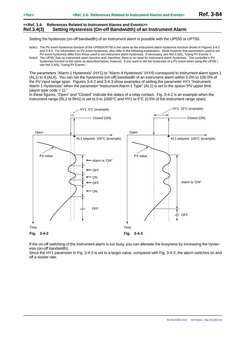
Ref. 3-84<Toc> <Ref. 3.4: References Related to Instrument Alarms and Events>
IM 05J01B02-01E 5th Edition : Mar.25,2005-00
<<Ref. 3.4: References Related to Instrument Alarms and Events>>Ref.3.4(3) Setting Hysteresis (On-off Bandwidth) of an Instrument Alarm
Setting the hysteresis (on-off bandwidth) of an instrument alarm is possible with the UP550 or UP750.
Note1: The PV event hysteresis function of the UP550/UP750 is the same as the instrument alarm hysteresis function shown in Figures 3-4-2and 3-4-3. For information on PV event hysteresis, also refer to the following explanation. (Note however that parameters used to setPV event hysteresis differ from those used to set instrument alarm hysteresis. If necessary, see Ref.3.4(5), “Using PV Events.”)
Note2: The UP35� has no instrument alarm function and, therefore, there is no need for instrument alarm hysteresis. The controller’s PVhysteresis function is the same as described below, however. If you want to set the hysteresis of a PV event when using the UP35�,see Ref.3.4(5), “Using PV Events.”
The parameters “Alarm-1 Hysteresis” (HY1) to “Alarm-4 Hysteresis” (HY4) correspond to instrument alarm types 1(AL1) to 4 (AL4). You can set the hysteresis (on-off) bandwidth of an instrument alarm within 0.0% to 100.0% ofthe PV input range span. Figures 3-4-2 and 3-4-3 show examples of setting the parameter HY1 “InstrumentAlarm-1 Hysteresis” when the parameter “Instrument Alarm-1 Type” (AL1) is set to the option “PV upper limit(alarm type code = 1).”In these figures, “Open” and “Closed” indicate the states of a relay contact. Fig. 3-4-2 is an example when theinstrument range (RL1 to RH1) is set to 0 to 1000°C and HY1 to 5°C (0.5% of the instrument range span).
Closed (ON)
Open
Time
AL1 setpoint: 100�C (example)
Closed (ON)
Open
Time
Fig. 3-4-3Fig. 3-4-2
AL1 setpoint: 100�C (example)
HY1: 15�C (example)HY1: 5�C (example)
PV value PV valueAlarm is “ON”
OFF
ON
OFF
ON
OFF
Alarm is “ON”
OFF
If the on-off switching of the instrument alarm is too busy, you can alleviate the busyness by increasing the hyster-esis (on-off bandwidth).Since the HY1 parameter in Fig. 3-4-3 is set to a larger value, compared with Fig. 3-4-2, the alarm switches on andoff a slower rate.

<Toc> <Ref. 3.4: References Related to Instrument Alarms and Events> Ref. 3-85
IM 05J01B02-01E 5th Edition : Mar.25,2005-00
● The parameter used here is summarized below.To change the settings of these parameters, see the Initial Settings user’s manual or the Parameters user’s manual for your controllermodel.
• Setup parameters (Alarm-related Parameters): HY1, HY2, HY3, HY4
UP750UP550
Code
D-RegisterNo.
919(The primary loop)
920(The primary loop)
921(The primary loop)
922(The primary loop)
Default
0.5% of PV inputrange span
0.5% of PV inputrange span
0.5% of PV inputrange span
0.5% of PV inputrange span
Description
Instrument alarm-1 hysteresis
Instrument alarm-2 hysteresis
Instrument alarm-3 hysteresis
Instrument alarm-4 hysteresis
0.0 to 100.0% of PVinput range span
0.0 to 100.0% of PVinput range span
0.0 to 100.0% of PVinput range span
Setting Range
0.0 to 100.0% of PVinput range span
HY1
HY2
HY3
HY4
The figure below is a partial view of the parameter map.Use this figure to guide you to the display for configuring the setup parameter discussed above.
Main menu
To PROG main menu of OperatingParameter Setup display
Sub menu
PARA
SP ALM CTL
SET
OK
SET DISP
Setup Parameter Map for UP550/UP750
Password
PT2.GSEG.TTMUSPT
UPMD
OPR2OPR1
MOD2MOD1
AR2AR1
PEH4PEH3PEH2PEH1
PEH7PEH6
AL1PEH8
PEH5
HY1AL4AL3AL2
HY4HY3HY2
AMD
CMLP CONF
DISP
RDVRHY
SPH2SPL2
SETSET
“HY1”

Ref. 3-86<Toc> <Ref. 3.4: References Related to Instrument Alarms and Events>
IM 05J01B02-01E 5th Edition : Mar.25,2005-00
<<Ref. 3.4: References Related to Instrument Alarms and Events>>Ref.3.4(4) Using the Sensor Ground Alarm
Using the sensor ground alarm is possible with the UP550 or UP750 (Note1).The alarm does not work however in the following cases.
• The controller is in manual operation mode.• The controller is at a stop (RESET mode).• The controller is in on-off control mode.• The controller is performing auto-tuning.
When the controller is used in heating/cooling control mode, relevant calculations are made with regard to inter-nally computed values obtained before the control output is split into the heating- and cooling-side portions.
Note1: If either UP550 or UP750 controller is used in cascade control mode or a UP550-1� controller is used in position-proportional controlmode, the sensor ground alarm function is disabled. Note that the UP35� has no sensor ground alarm function.
If the PV reading of the controller differs from the actual furnace temperature, you can judge the degree of deterio-ration in the sensor by observing a change in the output. For example, assume the controller indicates 100°Cwhile the actual furnace temperature is 110°C. At this point, the output value is larger than the one when the PVinput is 100°C. This condition is what the sensor ground alarm function is designed to detect. To be able to usethis function, you must have data on the range of steady-state output values (for example, the output value whenthe PV input is 100°C).
Heating furnace
Product
SSR
PV input's temperature value (obtained through the sensor) = 100�C
Manipulated output
Actual temperature = 110�C The manipulated output value is not
the value when the PV input is 100�C, but the value when the actual temperature is 110�C.
100�C
Fig. 3-4-4
A deterioration in the sensor is detected as described below. The controller judges it to be a sensor deteriorationand outputs an alarm signal if the moving average (Note2) of the control output falls outside the upper limit (ORHoperating parameter) and lower limit (ORL operating parameter) of the preset range despite the fact that control isstable and the PV input is within a given range of the target setpoint. The sensor ground alarm function works asshown in Fig. 3-4-4. The equation for calculating the moving average is given below (Note3). This calculationbegins when the PV value falls within the on-off rate detection band (ORB parameter).Note2: This moving average is referred to as the on-off rate (OR parameter).Note3: The on-off rate is five cycles’ worth of the moving average of control output. If this moving average falls outside the range from the ORL
parameter setpoint to the ORH parameter setpoint, the controller outputs an alarm signal.
Moving average = = on-off rate (OR parameter)5
OUTn + OUTn - 1 + OUTn + 2 + OUTn - 3 + OUTn - 4
where OUTn is the current output value, and the time interval of each of OUTn, OUTn-1, . . ., OUTn-4 is the cycletime.

<Toc> <Ref. 3.4: References Related to Instrument Alarms and Events> Ref. 3-87
IM 05J01B02-01E 5th Edition : Mar.25,2005-00
Set the on-off rate upper limit (ORH) and on-off rate lower limit (ORL) so that the range of the on-off rate is widerthan the range of steady-state control output values, as shown in Fig. 3-4-5. In addition, set the on-off rate detec-tion band close to the target setpoint. This is because the controller begins calculating the on-off rate when the PVinput value falls within the on-off rate detection band. Setting the band at a larger value forces the sensor groundalarm function to work before the output stabilizes. This means the sensor ground alarm turns on very frequently.
Target setpoint
ON OFFSensor ground alarm output
On-off rate upper limit (ORH)
Control of output value
On-off rate detection band (ORB)
Range of steady-state output
On-off rate detection band (ORB)
On-off rate lower limit (ORL)
Time length worth the “cycle time CT � five cycles”
On-off rate = moving average of control outputStart of on-off rate calculation
End of calculation
The sensor ground alarm turns on because the on-off rate has exceeded its upper limit.
PV input value
Fig. 3-4-5
● Parameters used to operate the sensor ground alarm are summarized below.You must configure two or more different types of parameter.To change the settings of these parameters, see the Initial Settings user’s manual or the Parameters user’s manual for your controllermodel.
• Setup parameters (Alarms-related Parameters): AL1 to AL4 (Note)
UP750UP550
Code
D-RegisterNo.
915
916
917
918
1: PV upper limit (Note)
2: PV lower limit (Note)
1: PV upper limit (Note)
2: PV lower limit (Note)
Description
Instrument alarm-1 type
Instrument alarm-2 type
Instrument alarm-3 type
Instrument alarm-4 type
Setting Range Default
• Set to “25” when using the sensor ground alarm for the primary loop.
• Set to “65” when using the sensor ground alarm for the secondary loop of the UP750.
AL1
AL2
AL3
AL4
Note: Each instrument alarm type parameter defaults to either code 1 “PV upper limit” or code 2 “PV lower limit”.To use the sensor ground alarm function, be sure to change each of these parameters to “25” (or “65”).

Ref. 3-88<Toc> <Ref. 3.4: References Related to Instrument Alarms and Events>
IM 05J01B02-01E 5th Edition : Mar.25,2005-00
• Setup parameters (Output-related Parameters): CT1 and CT2 (Note1)
UP750UP550
Code
D-Register No.
1240
1241
30 sec
30 sec
Description
Control output-1 cycle time
Control output-2 cycle time
Setting Range Default
1 to 1000 sec
CT1
CT2(Note2)
Note1: The parameters in this table are not displayed for a position-proportional control type UP550-1� controller.Note2: Displayed for the UP750 only.
The CT2 parameter is not displayed, however, for a UP750 controller of the cascade control type or a cascade control type with twouniversal inputs.
• Operating parameters (Operation-related Parameters): ORB, ORH and ORL
UP750UP550
Code
D-RegisterNo.
250 (The primary loop)280 (The secondary loop)
251 (The primary loop)281 (The secondary loop)
252 (The primary loop)282 (The secondary loop)
Default
1.0% of PVinput range span
100.0%
0.0%
Description
ON/OFF rate detection band
ON/OFF rate high limit
ON/OFF rate low limit
(ORL+1 digit) to 105.0%
-5.0% to (ORH-1 digit)
Setting Range
0.0 to 100.0% ofPV input range span
ORB
ORH
ORL
■ Setting the Required Parameters
To use the sensor ground alarm, some parameters must be set at the same time.These parameters are setup parameters “Aln”, “CTn”, “CTcn” and operating Parameters “ORB”, “ORH”, “ORL”.Carry out the parameter setting operation shown below.
Here we explain how to display the parameter setting display and to change the parameter values. Before carryingout these operations be sure to refer to the User’s Manuals Initial Settings and Parameter Map of the controller.The parameter map is very helpful in finding the path to the setting display for a particular parameter.
1: Referring to the User’s Manual above, displaythe setup parameter main menu [PARA].Then, display the submenu [ALM].
2: Press the SET/ENT key nine times to display theparameter “AL1”. With the UP750 or UP550,the sensor ground alarm can be set to any of“AL1”, “AL2”, “AL3” or “AL4”. When you wantto use “AL3”, press the SET/ENT key twice (more)and call up the “AL3” Setting display.
3: Set the parameter value to 25 using the / keys, then press the SET/ENT key to register
it.“25” must be set when you want to use thesensor ground alarm.
(Note: Set “65” for the secondary loop.)
Main menu
Sub menu
PARA
SP ALM CTL
SET
OK
SET DISP
Setup Parameter Map for UP550/UP750
Password
PT2.GSEG.TTMU
SPL1SPH1PNC
SPTOPR2OPR1
MOD2MOD1
R.TM
AR1
ZONAR2
R.MD
PEH4PEH3PEH2PEH1
PEH7PEH6
AL1PEH8
PEH5
HY1AL4AL3AL2
HY4HY3HY2
AMD
CMLP
DISP
To PROG main menu of OperatingParameter Setup display
RDVRHY
SPH2SPL2
SETSET
“AL1”

<Toc> <Ref. 3.4: References Related to Instrument Alarms and Events> Ref. 3-89
IM 05J01B02-01E 5th Edition : Mar.25,2005-00
4: After the above operation, set the cycle time“CT”. (The default value of “CT” is 30seconds.When the time is good, path the setting of“CT”.)
Display the setup parameter main menu[UPMD] and then, display the submenu [OUT].Press the SET/ENT key 3 times to display theparameter “CT”.Adjust the cycle time value using the /
keys, and press the key to register it.
SMCSMPUTM
P.L2P.H2P.D2
PARA
MD IN OUT VALV
RL1RH1UNI1IN1
DP1
OT1
BO1SL1SH1
RJC
RL3RH3UN3IN3
DP3
BO3SL3SH3
A3HA2L
A3L
CT1OT2
CTc1CT2
AO2AO1CTc2
AO3
SETSET
R485
STPPRIBPSPSL
RP.TADRDLN
SETSET
TR.TV.HV.L
V.MD
V.RSV.AT
INIT
SET
TEST
INI
SET
Setup Parameter Map for UP550/UP750
Password
UPMDCMLP CONF
SET
OK+
+
Main menu
Operating ParameterSetting display
A1LA1H
A2H
“CT1”
5: After the above operation, pressing the SET/ENT
key for at least 3 seconds to go back to theoperating display.
6: Then, press the SET/ENT key for at least 3 secondsagain to display the operating parameter mainmenu [PROG].Press key once to display main menu[LP1].Then, display the submenu [PAR].
7: Press the SET/ENT key 5 times to display theparameter “ORB”.Set the ON/OFF rate detection band valueusing the / keys, then press the SET/ENT
key to register it.
8: Press the SET/ENT key once to display the param-eter “ORH”.Set the ON/OFF rate high limit value using the
/ keys, then press the SET/ENT key toregister it.
9: Press the SET/ENT key once to display the param-eter “ORL”.Set the ON/OFF rate low limit value using the
/ keys, then press the SET/ENT key toregister it.
SET3S Main menu
Sub menu
FLBSSCAT
ORLORHORB
S.TM
LP1
PAR 1.PID 7.PID 8.PID
SET
SET
SET
1.I1.P
1.OH1.D
1.MR1.OL
1.H
1.Pc1.DR
1.Ic
1.Hc1.Dc
1.DB1.PO1.Oc
SET
7.I7.P
7.OH7.D
7.MR7.OL
7.H
7.Pc7.DR
7.Ic
7.Hc7.Dc
7.DB7.PO7.Oc
SET
8.I8.P
8.OH8.D
8.MR8.OL
8.H
8.Pc8.DR
8.Ic
8.Hc8.Dc
8.DB8.PO8.Oc
PROG
orSET3S
DISP
DISP
AL
Operating display
Operating Parameter Map for UP550/750
“ORB”
The parameter setting operation for the sensor ground alarm is completed.Pressing the key for at least 3 seconds to go back to the operating display.
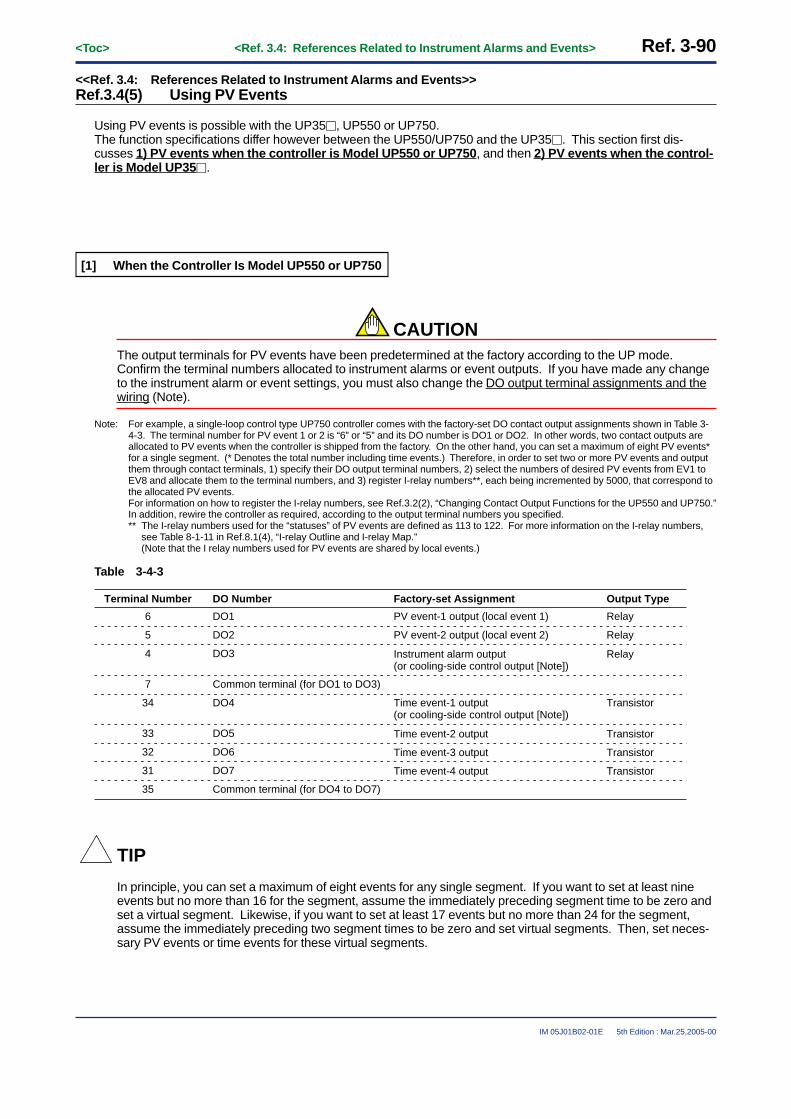
Ref. 3-90<Toc> <Ref. 3.4: References Related to Instrument Alarms and Events>
IM 05J01B02-01E 5th Edition : Mar.25,2005-00
<<Ref. 3.4: References Related to Instrument Alarms and Events>>Ref.3.4(5) Using PV Events
Using PV events is possible with the UP35�, UP550 or UP750.The function specifications differ however between the UP550/UP750 and the UP35�. This section first dis-cusses 1) PV events when the controller is Model UP550 or UP750, and then 2) PV events when the control-ler is Model UP35�.
[1] When the Controller Is Model UP550 or UP750
CAUTIONThe output terminals for PV events have been predetermined at the factory according to the UP mode.Confirm the terminal numbers allocated to instrument alarms or event outputs. If you have made any changeto the instrument alarm or event settings, you must also change the DO output terminal assignments and thewiring (Note).
Note: For example, a single-loop control type UP750 controller comes with the factory-set DO contact output assignments shown in Table 3-4-3. The terminal number for PV event 1 or 2 is “6” or “5” and its DO number is DO1 or DO2. In other words, two contact outputs areallocated to PV events when the controller is shipped from the factory. On the other hand, you can set a maximum of eight PV events*for a single segment. (* Denotes the total number including time events.) Therefore, in order to set two or more PV events and outputthem through contact terminals, 1) specify their DO output terminal numbers, 2) select the numbers of desired PV events from EV1 toEV8 and allocate them to the terminal numbers, and 3) register I-relay numbers**, each being incremented by 5000, that correspond tothe allocated PV events.For information on how to register the I-relay numbers, see Ref.3.2(2), “Changing Contact Output Functions for the UP550 and UP750.”In addition, rewire the controller as required, according to the output terminal numbers you specified.** The I-relay numbers used for the “statuses” of PV events are defined as 113 to 122. For more information on the I-relay numbers,
see Table 8-1-11 in Ref.8.1(4), “I-relay Outline and I-relay Map.”(Note that the I relay numbers used for PV events are shared by local events.)
Table 3-4-3
Terminal Number
6
DO Number
DO1
Factory-set Assignment
PV event-1 output (local event 1)
5 DO2 PV event-2 output (local event 2)
Instrument alarm output (or cooling-side control output [Note])
Time event-2 output
4 DO3
7 Common terminal (for DO1 to DO3)
34 DO4 Time event-1 output (or cooling-side control output [Note])
Output Type
Relay
Relay
Relay
Transistor
Transistor
33 DO5
Time event-3 output Transistor32 DO6
Time event-4 output Transistor31 DO7
35 Common terminal (for DO4 to DO7)
TIP
In principle, you can set a maximum of eight events for any single segment. If you want to set at least nineevents but no more than 16 for the segment, assume the immediately preceding segment time to be zero andset a virtual segment. Likewise, if you want to set at least 17 events but no more than 24 for the segment,assume the immediately preceding two segment times to be zero and set virtual segments. Then, set neces-sary PV events or time events for these virtual segments.

<Toc> <Ref. 3.4: References Related to Instrument Alarms and Events> Ref. 3-91
IM 05J01B02-01E 5th Edition : Mar.25,2005-00
■ Types of PV Event Available with UP550/UP750
A PV event is a function used to output a PV alarm signal or a deviation alarm signal that has been set in advanceduring program operation. The preset conditions of a PV event are retained even after the end of a given programsegment.
The types of PV events available with the UP550/UP750 are summarized in Table 3-4-4. Use the EVn, TYn andPEn program parameters shown in the table to change the type of PV event or set its value. Confirm the factory-set values and change them (or set new values) only if necessary.
Table 3-4-4
Alarm Action Alarm ActionAlarm Type
CodeAlarm Type
CodeAlarm Type “Open” and “Closed” refer to the
state of a relay contact and “On” and “Off” the state of a lamp.
Contactclosed in
case of alarm
Contact opened in case of alarm
Contactclosed in
case of alarm
Contact opened in case of alarm
Alarm Type
No alarm OFF
PV upper limit
PV lower limit
Alarm setpoint
Closed (On)
Hysteresis
PV value
(Off) Open
De-energizationin case of deviation lower-limit
alarmDeviation setpoint
Target setpoint
Open (On)
Hysteresis
PV value
Closed(Off)
Closed (On)
Hysteresis
Open (Off)
Alarm setpoint PV value
Deviationupper/lower
limits
Target setpoint
PV value
Hysteresis Hysteresis
Deviation setpoint
Closed (On) Open(Off)
Closed (On)
Deviationupper limit
Hysteresis
PV value
Open (Off)
Target setpointDeviation setpoint
Closed (On)
Withindeviation
upper/lowerlimits Deviation setpoint
Target setpoint
PV value
Hysteresis Hysteresis
Open (Off)Open (Off)
Closed(On)
Deviationlower limit
PV valueTarget setpoint
Deviation setpoint
Open (Off)
Hysteresis
Closed(On)
De-energizationin case of PV
upper-limitalarm
De-energizationin case of PV
lower-limitalarm
PV value
Open (On)
Alarm setpoint
Hysteresis
Closed (Off)
De-energizationin case of deviation upper-limit
alarm PV value
Open (On)
Target setpoint
Deviation setpoint
Hysteresis
Closed(Off)
Alarm setpoint
Hysteresis
PV value
Open (On) Closed (Off)
“Open” and “Closed” refer to the state of a relay contact and “On” and “Off” the state of a lamp.
Setpointupper limit
28
68
29
69
Alarm setpointSetpoint
Hysteresis Hysteresis
Setpointlower limit
Hysteresis Hysteresis
Alarm setpoint Setpoint
Output valueupper limit
70
71
Alarm setpointOutput value
Output valuelower limit
Alarm setpoint Output value
30
31
15
5
1
41
2
42
3
43
4
44
6
46
7
47
9
49
10
50
8
48
Alarm type codes 1 to 10 and 28 to 31 in the table above are assigned for the primary loop, while alarm type codes 41 to 50 and 68 to71 are assigned for the secondary loop.

Ref. 3-92<Toc> <Ref. 3.4: References Related to Instrument Alarms and Events>
IM 05J01B02-01E 5th Edition : Mar.25,2005-00
● Parameters used here are summarized below.To change the settings of these parameters, see the Initial Settings user’s manual or the Parameters user’s manual for your controllermodel.
• Program parameters (Parameters for Setting the Event Action): EVn, TYn and PEn
UP750UP550
Code
Default
0 (unregistered)
OFF (unregistered)
100.0% for upper limit0.0% for lower limit0.0% of PV input range span
100.0% for upper limit0.0% for lower limit
Description
Event number
PV event type
PV event setpoint
OFF, 1 to 10, or 28 to 31 (Note4)(41 to 50, or 68 to 71) (Note5)
• -100.0% to 100.0% of ←←←PV input range for PV/Setpoint alarms
• -100.0% to 100.0% of ←←←PV input range span for deviation alarms
• -5.0% to 105.0% for ←←←output value alarms
Setting Range
0, or 21 to 28 (Note3)EVn(Note2)
TYn(Note2)
PEn(Note2)
116 to 139
B-Register No. (Note1)
Note1: These parameters are supported by B registers 116 to 139.Note2: n denotes the event number and takes a value from 1 to 8, meaning there are eight events. The number is the total sum including both
PV events and time events.Note3: “0” means no events are used (registered). To use PV events, be sure to set a value from 21 to 28 to specify the event number n (1 to
8). For example, specify EV1 as PV event 1 by setting the EVn parameter to “21”. (For time events, use a value from 1 to 16.)Note4: For more information on the setting range, see “Alarm Type Code” in Table 3-4-4.Note5: These setpoints are for the secondary loop or loop 2. See “Alarm Type Code” in Table 3-4-4, for more information on the setting range.

<Toc> <Ref. 3.4: References Related to Instrument Alarms and Events> Ref. 3-93
IM 05J01B02-01E 5th Edition : Mar.25,2005-00
[2] When the Controller Is Model UP35�
You can separately set two events each for program pattern 1 and program pattern 2. The types of PV eventavailable with the UP35� are summarized in Table 3-4-5. Use the nAL1, nAL2, nA1 and nA2 program parametersshown in the table to change the type of PV event or set its value. Confirm the factory-set values and changethem (or set new values) only if necessary.
Table 3-4-5
Alarm Action Alarm ActionAlarm Type
CodeAlarm Type
CodeAlarm Type “Open” and “Closed” refer to the
state of a relay contact and “On” and “Off” the state of a lamp.
Contactclosed in
case of alarm
Contact opened in case of alarm
Contactclosed in
case of alarm
Contact opened in case of alarm
Alarm Type
No alarm OFF
PV upper limit
PV lower limit
Alarm setpoint
Closed (On)
Hysteresis
PV value
(Off) Open
De-energizationin case of deviation lower-limit
alarmDeviation setpoint
Target setpoint
Open (On)
Hysteresis
PV value
Closed(Off)
Closed (On)
Hysteresis
Open (Off)
Alarm setpoint PV value
Deviationupper/lower
limits
Target setpoint
PV value
Hysteresis Hysteresis
Deviation setpoint
Closed (On) Open(Off)
Closed (On)
Deviationupper limit
Hysteresis
PV value
Open (Off)
Target setpointDeviation setpoint
Closed (On)
Withindeviation
upper/lowerlimits Deviation setpoint
Target setpoint
PV value
Hysteresis Hysteresis
Open (Off)Open (Off)
Closed(On)
Deviationlower limit
PV valueTarget setpoint
Deviation setpoint
Open (Off)
Hysteresis
Closed(On)
De-energizationin case of PV
upper-limitalarm
De-energizationin case of PV
lower-limitalarm
PV value
Open (On)
Alarm setpoint
Hysteresis
Closed (Off)
De-energizationin case of deviation upper-limit
alarm PV value
Open (On)
Target setpoint
Deviation setpoint
Hysteresis
Closed(Off)
Alarm setpoint
Hysteresis
PV value
Open (On) Closed (Off)
“Open” and “Closed” refer to the state of a relay contact and “On” and “Off” the state of a lamp.
5
1
2
3
4
6
7
9
10
8

Ref. 3-94<Toc> <Ref. 3.4: References Related to Instrument Alarms and Events>
IM 05J01B02-01E 5th Edition : Mar.25,2005-00
● Parameters used here are summarized below.To change the settings of these parameters, see the Initial Settings user’s manual or the Parameters user’s manual for your controllermodel.
• Program parameters: n.AL1, n.A1, n.AL2 and n.A2 (Note)
UP35�
Code
Description
PV event-1 type
PV event-1 setpoint
PV event-2 setpoint
PV event-2 type
n.AL1(Note)
n.A1(Note)
n.AL2(Note)
n.A2(Note)
132 (for pattern 1)162 (for pattern 2)
D-Register No.
133 (for pattern 1)163 (for pattern 2)
134 (for pattern 1)164 (for pattern 2)
131 (for pattern 1)161 (for pattern 2)
Default
OFF (unregistered)
OFF (unregistered)
100.0% for upper limit0.0% for lower limit
100.0% for upper limit0.0% for lower limit
0.0% of PV input range span
OFF, or 1 to 10
Setting Range
OFF, or 1 to 10
• -100.0% to 100.0% of ←←←PV input range for PV/setpoint alarms(The other settings are the same as those of n.A1 parameter.)
• -100.0% to 100.0% of ←←←PV input range for PV/setpoint alarms
• -100.0% to 100.0% of ←←←PV input range span for deviation alarms
Note: n is either the value 1 or 2. Use this value to discriminate the parameter’s application between pattern 1 and pattern 2.

<Toc> <Ref. 3.4: References Related to Instrument Alarms and Events> Ref. 3-95
IM 05J01B02-01E 5th Edition : Mar.25,2005-00
■ Hysteresis of PV Events
You can set hysteresis for a PV event.
[1] Setting Hysteresis for UP550/UP750
Since you can set a maximum of eight PV events (EVn = 1 to 8) for the UP550/UP750, you can set as manyvalues of hysteresis for these PV events.Use the setup parameters PEH1 to ZPEH8 shown in the table below to set hysteresis. The functionality of PVevent hysteresis is the same as that of instrument alarm hysteresis. For more information on the PV eventhysteresis, see Ref.3.4(3), “Setting Hysteresis (On-off Bandwidth) for Instrument Alarms.”
● Parameters used here are summarized below.To change the settings of these parameters, see the Initial Settings user’s manual or the Parameters user’s manual for your controllermodel.
• Setup parameters (Alarm-related Parameters): PEH1 to PEH8
UP750UP550
Code
Setting Range
0.0% to 100.0% of PV input range span
PEH1
PEH2
PEH3
PEH4
D-Register Number
907
908
909
910
911
912
913
914
Factory-set or Initial Value
0.5% of PV input range span
0.5% of PV input range span
0.5% of PV input range span
0.5% of PV input range span
0.5% of PV input range span
0.5% of PV input range span
0.5% of PV input range span
0.5% of PV input range span
Description
PV event-1 hysteresis
PV event-2 hysteresis
PV event-3 hysteresis
PV event-4 hysteresis
PV event-5 hysteresis
PV event-6 hysteresis
PV event-7 hysteresis
PV event-8 hysteresis
PEH5
PEH6
PEH7
PEH8
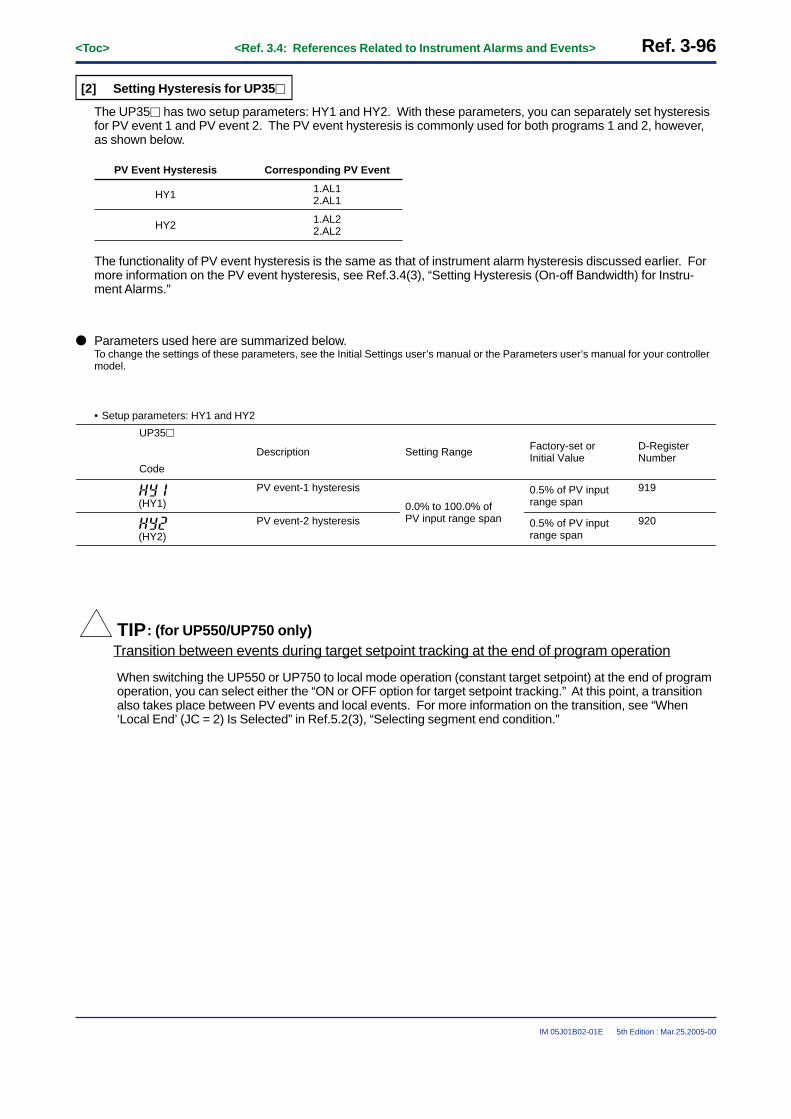
Ref. 3-96<Toc> <Ref. 3.4: References Related to Instrument Alarms and Events>
IM 05J01B02-01E 5th Edition : Mar.25,2005-00
[2] Setting Hysteresis for UP35�
The UP35� has two setup parameters: HY1 and HY2. With these parameters, you can separately set hysteresisfor PV event 1 and PV event 2. The PV event hysteresis is commonly used for both programs 1 and 2, however,as shown below.
HY1
PV Event Hysteresis Corresponding PV Event
1.AL12.AL1
HY2 1.AL22.AL2
The functionality of PV event hysteresis is the same as that of instrument alarm hysteresis discussed earlier. Formore information on the PV event hysteresis, see Ref.3.4(3), “Setting Hysteresis (On-off Bandwidth) for Instru-ment Alarms.”
● Parameters used here are summarized below.To change the settings of these parameters, see the Initial Settings user’s manual or the Parameters user’s manual for your controllermodel.
• Setup parameters: HY1 and HY2
Setting Range
0.0% to 100.0% of PV input range span
UP35�
Code
919
D-Register Number
920
0.5% of PV input range span
Factory-set or Initial Value
0.5% of PV input range span
Description
PV event-1 hysteresis
PV event-2 hysteresis
(HY1)
(HY2)
TIP: (for UP550/UP750 only)Transition between events during target setpoint tracking at the end of program operation
When switching the UP550 or UP750 to local mode operation (constant target setpoint) at the end of programoperation, you can select either the “ON or OFF option for target setpoint tracking.” At this point, a transitionalso takes place between PV events and local events. For more information on the transition, see “When‘Local End’ (JC = 2) Is Selected” in Ref.5.2(3), “Selecting segment end condition.”

<Toc> <Ref. 3.4: References Related to Instrument Alarms and Events> Ref. 3-97
IM 05J01B02-01E 5th Edition : Mar.25,2005-00
<<Ref. 3.4: References Related to Instrument Alarms and Events>>Ref.3.4(6) Using Time Events
Using time events is possible with the UP35�, UP550 or UP750.
The function specifications differ however between the UP550/UP750 and the UP35�. This section first dis-cusses 1) time events when the controller is Model UP550 or UP750, and then 2) time events when thecontroller is Model UP35�.
[1] When the Controller Is Model UP550 or UP750
CAUTIONThe output terminals for Time events have been predetermined at the factory according to the UP mode.Confirm the terminal numbers allocated to instrument alarms or event outputs. If you have made any changeto the instrument alarm or event settings, you must also change the DO output terminal assignments and thewiring (Note).
Note: For example, a single-loop control type UP750 controller comes with the factory-set DO contact output assignments shown in Table 3-4-6. The terminal numbers for time events 1 to 4 is “34”, “33”, “32” and “31” and its DO numbers are DO4 or DO7. In other words, fourcontact outputs are allocated to time events when the controller is shipped from the factory. On the other hand, you can set a maximumof eight time events* for a single segment. (* Denotes the total number including PV events. See TIP below.) Therefore, in order to setfive or more time events and output them through contact terminals, 1) specify their DO output terminal numbers, 2) select the numbersof desired time events from EV1 to EV8 and allocate them to the terminal numbers, and 3) register I-relay numbers**, each beingincremented by 5000, that correspond to the allocated time events.For information on how to register the I-relay numbers, see Ref.3.2(2), “Changing Contact Output Functions for the UP750 and UP550.”In addition, rewire the controller as required, according to the output terminal numbers you specified.** The I-relay numbers used for the “statuses” of time events are defined as 129 to 154. For more information on the I-relay numbers,
see Table 8-1-11 in Ref.8.1(4), “I-relay Outline and I-relay Map.”(Note that the I relay numbers used for PV events are shared by local events.)
Table 3-4-6
Terminal Number
6
DO Number
DO1
Factory-set Assignment
PV event-1 output (local event 1)
5 DO2 PV event-2 output (local event 2)
Instrument alarm output (or cooling-side control output [Note])
Time event-2 output
4 DO3
7 Common terminal (for DO1 to DO3)
34 DO4 Time event-1 output (or cooling-side control output [Note])
Output Type
Relay
Relay
Relay
Transistor
Transistor
33 DO5
Time event-3 output Transistor32 DO6
Time event-4 output Transistor31 DO7
35 Common terminal (for DO4 to DO7)
TIPIn principle, you can set a maximum of eight events for any single segment. If you want to set at least nineevents but no more than 16 for the segment, assume the immediately preceding segment time to be zero andset a virtual segment. Likewise, if you want to set at least 17 events but no more than 24 for the segment,assume the immediately preceding two segment times to be zero and set virtual segments. Then, set neces-sary PV events or time events for these virtual segments.
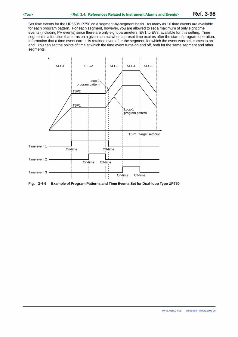
Ref. 3-98<Toc> <Ref. 3.4: References Related to Instrument Alarms and Events>
IM 05J01B02-01E 5th Edition : Mar.25,2005-00
Set time events for the UP550/UP750 on a segment-by-segment basis. As many as 16 time events are availablefor each program pattern. For each segment, however, you are allowed to set a maximum of only eight timeevents (including PV events) since there are only eight parameters, EV1 to EV8, available for this setting. Timesegment is a function that turns on a given contact when a preset time expires after the start of program operation.Information that a time event carries is retained even after the segment, for which the event was set, comes to anend. You can set the points of time at which the time event turns on and off, both for the same segment and othersegments.
SEG4SEG3SEG2
TSP2
TSP1
SEG1 SEG5
Time event 1
Time event 2
Time event 3
Loop-2program pattern
Loop-1 program pattern
TSPn: Target setpoint
On-time Off-time
On-time Off-time
On-time Off-time
Fig. 3-4-6 Example of Program Patterns and Time Events Set for Dual-loop Type UP750

<Toc> <Ref. 3.4: References Related to Instrument Alarms and Events> Ref. 3-99
IM 05J01B02-01E 5th Edition : Mar.25,2005-00
● UP550/UP750’s Parameters for Setting Time EventsTo change the settings of these parameters, see the Initial Settings user’s manual or the Parameters user’s manual for your controllermodel.
• Program parameters (Parameters for Setting the Event Action): EVn, ONn and OFFn
UP750UP550
Code
Default
0 (unregistered)
OFF (unused)
OFF (unused)
Description
Event number
On time of time event
Off time of time event
OFF, or 0.00 to 99.59(“Hour:minute” or “minute:second”) (Note4)
OFF, or 0.00 to 99.59(“Hour:minute” or “minute:second”) (Note4)
Setting Range
0, or 1 to 16 (Note3)EVn(Note2)
ONn(Note2)
OFFn(Note2)
116 to 139
B-Register No.(Note1)
Note1: These parameters are supported by B registers 116 to 139.Note2: n denotes the event number and takes a value from 1 to 8, meaning there are eight events. The number is the total sum including both
PV events and time events.Note3: “0” means no events are used (registered). To use PV events, be sure to set a value from 1 to 16 to specify the event number n (1 to 8).
For example, specify EV1 as PV event 1 by setting the EVn parameter to “1”. (For PV events, use a value from 21 to 28.)Note4: To set the time unit (“hour:minute” or “minute:second”), use the setup parameter TMU. The time unit is:
• “hour:minute”, if TMU is 0 (factory-set default), or• “minute:second”, if TMU is 1.
For more information on the time unit, see Ref.5.1(1), “Selecting the Segment Setting Method (Time Setting Method or Ramp GradeSetting Method).”

Ref. 3-100<Toc> <Ref. 3.4: References Related to Instrument Alarms and Events>
IM 05J01B02-01E 5th Edition : Mar.25,2005-00
[2] When the Controller Is Model UP35�
If your controller is Model UP35�, you can set a pair of time events for each of program patterns 1 and 2. TheUP35�’s time segment turns on a given contact output when the preset “time segment on-time” expires after thestart of the first segment of a program pattern. Likewise, the time segment turns off the contact output when thepreset “time segment off-time” expires.
For program 1, you can set the on-time and off-time of a time event using the 1.EON and 1.EOF parametersshown in the following table.
● Parameters used to set the UP35�’s time events are summarized below.To change the settings of these parameters, see the Initial Settings user’s manual or the Parameters user’s manual for your controllermodel.
• Program parameters (Parameters for Setting Event Actions): n.EON and nEOF
UP35�
Code
Setting Range
OFF, or 0.00 to 99.59 (“hour:minute” or “minute:second”) (Note2)
OFF, or 0.00 to 99.59 (“hour:minute” or “minute:second”) (Note2)
135 (1.EON)165 (2.EON)
D-Register No. (Note1)
136 (1.EOF)166 (2.EOF)
OFF (unused)
Default
OFF (unused)
Description
Time event on-time
Time event off-time
n.(n.EON) (Note1)
n.(n.EOF) (Note1)
Note1: n takes a value of either 1 or 2. Use this value to discriminate the parameter’s application between program patterns 1 and 2.Note2: To set the time unit (“hour:minute” or “minute:second”), use the setup parameter TMU. The time unit is:
• “hour:minute”, if TMU is 0 (factory-set default), or• “minute:second”, if TMU is 1.

<Toc> <Ref. 3.4: References Related to Instrument Alarms and Events> Ref. 3-101
IM 05J01B02-01E 5th Edition : Mar.25,2005-00
<<Ref. 3.4: References Related to Instrument Alarms and Events>>Ref.3.4(7) Using Local Events
Using local events is possible with the UP550 or UP750.Local events work only if the controller is in local mode.(The UP35� does not have local mode and, therefore, has no local events.)
CAUTIONThe output terminals for each events have been predetermined at the factory according to the UP mode.Confirm the terminal numbers allocated to instrument alarms or event outputs. If you have made any changeto the instrument alarm or event settings, you must also change the DO output terminal assignments and thewiring (Note).
Note: For example, a single-loop control type UP750 controller comes with the factory-set DO contact output assignments shown in Table 3-4-7. The terminal numbers for PV events 1 and 2 is “6” and “5” and its DO numbers are DO1 and DO2. In other words, two contactoutputs are allocated to PV events when the controller is shipped from the factory.On the other hand, these output terminals for PV events are changed to those for local events (E21A and E22A) because their I-relaynumbers are shared as noted below. Therefore, set the “local event type” and “local event setpoint” for each of these two local events,E21A and E22A, to be able to use them.In order to allocate three or more local events to output terminals, 1) specify the DO numbers of output terminals to be used, 2) selectthe numbers of desired local events from E21A to E28A, and 3) register I-relay numbers*, each being incremented by 5000, thatcorrespond to the allocated local events.For information on how to register the I-relay numbers, see Ref.3.2(2), “Changing Contact Output Functions for the UP750 and UP550.”In addition, rewire the controller as required, according to the output terminal numbers you specified.* Local events and PV events share the same I-relay numbers. In addition, the I-relay numbers used for the “statuses” of these
events are defined as 113 to 122. For more information on the I-relay numbers, see Table 8-1-11 in Ref.8.1(4), “I-relay Outline and I-relay Map.”(Note that the I relay numbers used for PV events are shared by local events.)
Table 3-4-7
Terminal Number
6
DO Number
DO1
Factory-set Assignment
PV event-1 output (local event 1)
5 DO2 PV event-2 output (local event 2)
Instrument alarm output (or cooling-side control output [Note])
Time event-2 output
4 DO3
7 Common terminal (for DO1 to DO3)
34 DO4 Time event-1 output (or cooling-side control output [Note])
Output Type
Relay
Relay
Relay
Transistor
Transistor
33 DO5
Time event-3 output Transistor32 DO6
Time event-4 output Transistor31 DO7
35 Common terminal (for DO4 to DO7)

Ref. 3-102<Toc> <Ref. 3.4: References Related to Instrument Alarms and Events>
IM 05J01B02-01E 5th Edition : Mar.25,2005-00
The UP550/UP750’s local event types are summarized in Table 3-4-8. Use the program parameters E21A toE28A and E21B to E28B shown in Table 3-4-8 to change the type of local event or set its value. Each local eventtype is set to OFF (unused) when the controller is shipped from the factory.Change the factory-set values (or set new values) only if local events are necessary.
Table 3-4-8
Alarm Action Alarm ActionAlarm Type
CodeAlarm Type
CodeAlarm Type “Open” and “Closed” refer to the
state of a relay contact and “On” and “Off” the state of a lamp.
Contactclosed in
case of alarm
Contact opened in case of alarm
Contactclosed in
case of alarm
Contact opened in case of alarm
Alarm Type
No alarm OFF
PV upper limit
PV lower limit
Alarm setpoint
Closed (On)
Hysteresis
PV value
(Off) Open
De-energizationin case of deviation lower-limit
alarmDeviation setpoint
Target setpoint
Open (On)
Hysteresis
PV value
Closed(Off)
Closed (On)
Hysteresis
Open (Off)
Alarm setpoint PV value
Deviationupper/lower
limits
Target setpoint
PV value
Hysteresis Hysteresis
Deviation setpoint
Closed (On) Open(Off)
Closed (On)
Deviationupper limit
Hysteresis
PV value
Open (Off)
Target setpointDeviation setpoint
Closed (On)
Withindeviation
upper/lowerlimits Deviation setpoint
Target setpoint
PV value
Hysteresis Hysteresis
Open (Off)Open (Off)
Closed(On)
Deviationlower limit
PV valueTarget setpoint
Deviation setpoint
Open (Off)
Hysteresis
Closed(On)
De-energizationin case of PV
upper-limitalarm
De-energizationin case of PV
lower-limitalarm
PV value
Open (On)
Alarm setpoint
Hysteresis
Closed (Off)
De-energizationin case of deviation upper-limit
alarm PV value
Open (On)
Target setpoint
Deviation setpoint
Hysteresis
Closed(Off)
Alarm setpoint
Hysteresis
PV value
Open (On) Closed (Off)
“Open” and “Closed” refer to the state of a relay contact and “On” and “Off” the state of a lamp.
Setpointupper limit
28
68
29
69
Alarm setpointSetpoint
Hysteresis Hysteresis
Setpointlower limit
Hysteresis Hysteresis
Alarm setpoint Setpoint
Output valueupper limit
70
71
Alarm setpointOutput value
Output valuelower limit
Alarm setpoint Output value
30
31
15
5
1
41
2
42
3
43
4
44
6
46
7
47
9
49
10
50
8
48
Alarm type codes 1 to 10 and 28 to 31 in the table above are assigned for the primary loop, while alarm type codes 41 to 50 and 68 to71 are assigned for the secondary loop.

<Toc> <Ref. 3.4: References Related to Instrument Alarms and Events> Ref. 3-103
IM 05J01B02-01E 5th Edition : Mar.25,2005-00
● Parameters used to set local events are summarized below.To change the settings of these parameters, see the Initial Settings user’s manual or the Parameters user’s manual for your controllermodel.
• Program parameters (Local Setpoint Parameters): E21A to E28A and E21B to E28B
UP750UP550
Code
This range of symbols covers the parameters E22A to E27A and E22B to E27B. These parameters are allocated to the D-registers numbered 106 to 117. The setting range and factory-set default of the parameter E2xA are the same as the parameter E21A. Likewise, the setting range and factory-set default of the parameter E2xB are the same as the parameter E21B.
↓↓↓↓
E21A
E21B
Default
OFF (unused)
100.0% for upper limit0.0% for lower limit0.0% of PV input range span
100.0% for upper limit0.0% for lower limit
OFF (unused)
(Note3)
Description
Local event-21 type
Local event-21 setpoint
Local event-28 type
Local event-28 setpoint
OFF, 1 to 10, or 28 to 31 (Note1)(41 to 50, or 68 to 71) (Note2)
• -100.0% to 100.0% of ←←PV input range for PV/Setpoint alarms
• -100.0% to 100.0% of ←←PV input range span for deviation alarms
• -5.0% to 105.0% for ←←output value alarms
Setting Range
OFF, 1 to 10, or 28 to 31 (Note1)(41 to 50, or 68 to 71) (Note2)
(Note3)
E28A
E28B
105
104
118
D-Register No.
119
Note1: For more information on the setting range, see “Alarm Type Code” in Table 3-4-8.Note2: These setpoints are for the secondary loop or loop 2. See “Alarm Type Code” in Table 3-4-8, for more information on the setting range.Note3: Same as the setting range and factory-set default of the parameter E21B “Local Event-21 Setpoint.”

Blank Page

<Toc> <Ref. 4.1: References Related to Target Setpoints> Ref. 4-1
IM 05J01B02-01E 5th Edition : Mar.25,2005-00
Ref.4.1: References Related to Target Setpoints
IMPORTANT: Applicable models of this section
UP750 UP550 UP35� UT750 UT5�� UT4�0 UT3��
None UT750-��None None UT5��-�� UT4�0-�� UT3��-��
Note: Some of the functions below are not available on certain models.For more information, see those sections.
This section contains reference information on the following aspects of Target Setpoints.Refer to this information and change parameters only if necessary.
(1) Using Multiple Target Setpoints (8 Max.)(2) Selecting PID selection method (Target SP selection or Zone PID selection)(3) Limiting Changes in Target Setpoints(4) Setting ramp grades when switching between target setpoints

Ref. 4-2<Toc> <Ref. 4.1: References Related to Target Setpoints>
IM 05J01B02-01E 5th Edition : Mar.25,2005-00
<<Ref. 4.1: References Related to Target Setpoints>>Ref.4.1(1) Using Multiple Target Setpoints (8 Max.)
The UT750, UT5�� and UT4�0 are designed so that you can set a maximum of eight target setpoints at a time.You can also set a maximum of eight target setpoints at a time for each loop in a controller mode of the UT750 orUT5�� that uses two loops (Note). In the case of the UT3��, you can set a maximum of four target setpoints ata time.(Note): To change the number of target setpoints, set the “GRP” setup parameter to a desired value from 1 to 8.
This feature is convenient in such applications where more than one product is manufactured at the same time.Set multiple target setpoints in advance and switch between them according to the type of product.You can set PID constants and other parameters separately for each individual target setpoint. However, appli-cable parameters will differ slightly according to the controller model. Parameters that can be set according to thetarget setpoints of each controller model are listed on the following parameter map. Verify the types of parameteravailable with your controller.
You can switch between target setpoints in any of the following ways:• Select a target setpoint number by key operation.• Use external contacts.• Use communication means.
The number of target setpoint can be changed (reduced) with the parameter “GRP” (PID group number).For example, when “5” is set to the “GRP”, only five PID group parameters (1.PID to 5.PID) can be displayed.
[1] When the Model Is UT750, UT550, UT551 or UT520
SET3S
Operating display
Mainmenu
Submenu+
FLBSSCAT
RTDNRUPR
RFLRBS
ORHORB
ORL
LP1 LP2 USR PY2 STUP
PAR 1.PID 7.PID 8.PID
Sameas
LP1
SET
SET
SET
1.A31.A21.A11.SP
1.I1.P1.A4
1.OH1.D
1.MR1.OL
1.H
1.Pc1.DR
1.Ic
1.Hc1.Dc
1.DB1.PO1.Oc
SET
7.A37.A27.A1
7.I7.P7.A4
7.OH7.D
7.MR7.OL
7.H
7.Pc7.DR
7.Ic
7.Hc7.Dc
7.DB7.PO7.Oc
SET
8.A38.A28.A18.SP
8.I8.P8.A4
8.OH8.D
8.MR8.OL
8.H
8.Pc8.DR
8.Ic
8.Hc8.Dc
8.DB8.PO8.Oc
MODE
orSET3S
+
7.SP
PY1
Parameters that can be set according to the each target setpoints.

<Toc> <Ref. 4.1: References Related to Target Setpoints> Ref. 4-3
IM 05J01B02-01E 5th Edition : Mar.25,2005-00
[2] When the Model Is UT450 or UT420
Operating display
Menu
Parameters (n.p etc.) that can be set according to the each target setpoints.
Use to change the display of the parameters.Operation parameters
SET/ENT key
SET/ENT key
SET/ENT key
Output high limit / heating-side output
high limit
Output low limit / cooling-side output
high limit
ON/OFF control hysteresis / heating-side
ON/OFF control hysteresis
Preset output / heating-sidepreset output
Proportional band / heating-side proportional band
Integral time / heating-side integral time
Derivative time / heating-side derivative time
Manual reset
Direct/reverse action switching
Cooling-side proportional band
Cooling-side integral time
Cooling-side derivative time
Cooling-side ON/OFF control hysteresis
Dead band
Cooling-side preset output
Alarm-2 setpoint
Alarm-3 setpoint
Alarm-4 setpoint
Remote/localswitching
Run/stopswitching
Target setpoint number selection
PID parameter display number
PV input filter
PV input bias
Setpoint ramp-up rate
Setpoint ramp-down rate
Ratio setting
Remote input bias
Remote input filter
ON/OFF rate detection band
ON/OFF rate high limit
ON/OFF rate low limit
Target setpoint-1
Target setpoint-2
Target setpoint-3
Target setpoint-4
Target setpoint-5
Target setpoint-6
Target setpoint-7
Target setpoint-8
Alarm-1 setpoint
Auto-tuning
SUPER function
[3] When the Model Is UT35� or UT32�
The UT35� and UT32� accept a maximum offour target setpoints. Therefore, if the zone PIDselection method is selected, three zones areformed since two reference points are set forfour target setpoints. In addition, the “RVD”reference deviation is assigned in advance tothe 4th target setpoint, making parametersetting easier.
Parameters (n.p etc.) that can be set according to the each target setpoints.
Menu
SET/ENT key
SET/ENT key
Operating display
Operation parametersSET/ENT keyUse to change the display of the parameters.
On-off rate
Heater open-circuit current setpoint 1
Heater open-circuit current setpoint 2
Heater open-circuit current measurement 1
Heater open-circuit current measurement 2
Alarm-2 setpoint
Alarm-3 setpoint
Alarm-1 setpoint
Target setpoint number selection
Setpoint ramp-up rate
Setpoint ramp-down rate
ON/OFF rate detection band
ON/OFF rate high limit
ON/OFF rate low limit
Target setpoint-1
Target setpoint-2
Target setpoint-3
Target setpoint-4
LL communication interface selection
Auto-tuning
SUPER function
PID parameter display number
PV input filter
PV input bias
ON/OFF control hysteresis / heating-side
ON/OFF control hysteresis
Direct/reverse action switching
Output high limit / heating-side output high limit
Output low limit / cooling-side output high limit
Cooling-side proportional band
Cooling-side integral time
Cooling-side derivative time
Dead band
Proportional band / heating-side proportional band
Integral time / heating-side integral time
Derivative time / heating-side derivative time
Manual reset
Zone PID reference point-1

Ref. 4-4<Toc> <Ref. 4.1: References Related to Target Setpoints>
IM 05J01B02-01E 5th Edition : Mar.25,2005-00
To set target setpoints and their associate parameters, such as PID constants, use the operating parameters listedbelow.The setting parameters differs depending on the controller model.Refer to the paragraph that is applicable to your model.
(1) When the Model Is UT750 or UT5��
Change parameters as explained in the User’s Manuals Initial Settings and Parameter Map.
• Operating parameters (Setpoint-, Alarm- and PID- related Parameters)(Heating/cooling control is not provided for the UT551 with embedded Ethernet.)
UT750
Code
Description Setting range
0.0 to100.0% of PV input range
0.0% of PV input range
Default D-register No.
UT5��
Code
n.SP(Note1)
Target setpoint-1n.(n.SP)
0.1 to 999.9%In heating/cooling control : 0.0 to 999.9% (Note4)
Refer to theTable 4-1-1
5.0%
Refer to theTable 4-1-1
Refer to theTable 4-1-1
n.P Promotional band / Heating-side proportional band (in heating/cooling control) (Note3)
n.(n.P)
OFF or 1 to 6000 sec. Refer to theTable 4-1-1
240 secondsn.I Integral time / Heating-side integral time (in heating/cooling control) (Note3)
n.(n.I)
OFF or 1 to 6000 sec. Refer to theTable 4-1-1
60 secondsn.D Derivative time / Heating-side derivative time (in heating/cooling control) (Note3)
n.(n.D)
-5.0 to 105.0%Heating side limiter in heating/cooling control : 0.0 to 105.0% (n.OL < n.OH)
Refer to theTable 4-1-1
100.0%n.OH Output high limit / Heating-side output high limit (in heating/cooling control) (Note3)
n.(n.OH)
SD (shut down, Note5) or -5.0 to 105.0% Cooling side limiter in heating/cooling control : 0.0 to 105.0% (n.OL < n.OH)
Refer to theTable 4-1-1
0.0%100.0% (in heating/cooling control)
n.OL Output low limit / Heating-side output low limit (in heating/cooling control) (Note3)
n.(n.OL)
-5.0 to 105.0% ( enabled when integral time “n.I” is OFF.)
Refer to theTable 4-1-1
50.0%n.MR Manual reset / Heating-side manual reset (in heating/cooling control) (Note3)
n.(n.MR)
0.0 to 100.0% of PV input range span
• Position proportional PID control or heating/cooling control : 0.0 to 100.0%
Refer to theTable 4-1-1
0.5% of PV input range span
0.5%
n.H ON/OFF control hysteresis
• Heating-side ON/OFF control hysteresis (in heating/cooling control)
n.(n.H)
• With UT750, REVERS : reverse action, DIRECT :direct action
• With UT5��, RVS : reverse action, DIR :direct action
Refer to theTable 4-1-1
< Continue >
REVERS (reverse action)
RVS (reverse action)
n.DR Direct / reverse action switching (Note6)
n.(n.DR)
• When PV alarm is used: 0.0 to 100.0% of PV input range
• When Deviation alarm is used: -100.0 to 100.0% of PV input range span
• When Timer alarm ( for alarm-1 only) is used: 00.00 to 99.59
• When PV alarm is used: 100.0%
• When Deviation alarm is used: 0.0%
n.A1 Alarm-1 setpoint (Note2)n.(n.A1)
n.A2 Alarm-2 setpoint (Note2)n.(n.A2)
n.A3 Alarm-3 setpoint (Note2)n.(n.A3)
n.A4 Alarm-4 setpoint (Note2)n.(n.A4)

<Toc> <Ref. 4.1: References Related to Target Setpoints> Ref. 4-5
IM 05J01B02-01E 5th Edition : Mar.25,2005-00
UT750
Code
Description Setting range Default D-register No.
UT5��
Code
0.0 to 999.9% (Note4) Refer to theTable 4-1-1
5.0%n.Pc Coolong-side proportional band (Note7)
n.(n.Pc)
OFF or 1 to 6000 sec. Refer to theTable 4-1-1
240 secondsn.Ic Cooling-side Integral time (Note7)
n.(n.Ic)
OFF or 1 to 6000 sec. Refer to theTable 4-1-1
60 secondsn.Dc Cooling-side Derivative time (Note7)
n.(n.Dc)
0.0 to 100.0% of PV input range span
Refer to theTable 4-1-1
Refer to theTable 4-1-1
0.5% of PV input range span
3.0%
n.Hc Cooling-side ON/OFF control hysteresis (Note7)
n.(n.Hc)
• In heating/cooling control: -100.0 to 50.0%
• In position proportional control: 1.0 to 10.0%
n.DB Dead band (Note8)n.(n.DB)
-5.0 to 105.0% of control output (MV)
Refer to theTable 4-1-1
0.0%n.PO Preset output / Heating-side preset out (in heating/cooling control) (Note9)
n.(n.PO)
-5.0 to 105.0% of control output (MV)
Refer to theTable 4-1-1
0.0%n.Oc Cooling-side preset out (in heating/cooling control) (Note7)
n.(n.Oc)
Note1: The prefix n in the table above represents the number of each of the parameters, such as target setpoints and their associate PIDconstants, listed in the table. Since a maximum of eight target setpoints are available with each of the UT750, UT550, UT551 andUT520, “n = 1 to 8” holds true.
Note2: The UT55�-�1, UT55�-�3, UT551-�C and UT551-�D are designed so that setting the “AMD” setup parameter, which is used to seta loop-1 alarm mode, to either “3”, “4” or “5” causes the n.A1 to n.A4 parameters for loop 2 to appear on the display. In this case, the“n.A1” to “n.A4” parameters may be used as the 5th to 8th alarm parameters for loop 1; this is not true with cascade control, however.
Note3: Not shown for on-off control; however, the parameter is shown for the on-off control mode of heating/cooling control.Note4: If the heating-side proportional band is set to “0.0” in heating/cooling control, the heating side goes into on-off control. Likewise, if the
cooling-side proportional band is set to “0.0”, the cooling side goes into on-off control.Note5: SD stands for “Shut Down”. It is configurable when the control output is 4 to 20 mA and the controller is in manual operation. At
shutdown, the control output is set to 0 mA.Note6: Not shown for heating/cooling control.Note7: Shown only for heating/cooling control. The parameter is shown in the [LP2] operating parameter main menu only if the controller is
performing heating/cooling control and the controller mode (UT mode) is either cascade control or cascade control with 2 universalinputs.
Note8: Shown only for position proportional PID control or heating/cooling control.Note9: If the controller mode (UT mode) is cascade control or cascade control with 2 universal inputs, the “n.PO” parameter is shown only in
the [LP2] operating parameter main menu.
Table 4-1-1 PID related parameter D-register numbers list (1st: for loop-1, 2nd: for loop-2, UT750, UT550 andUT551 only)
307308309310311312313314315316317318320321
n.In.Dn.OHn.OLn.MRn.Hn.DRn.Pcn.Icn.Dcn.Hcn.DBn.POn.Oc
507508509510511512513514515516517518520521
332333334335336337338339340341342343345346
532533534535536537538539540541542543545546
357358359360361362363364365366367368370371
557558559560561562563564565566567568570571
382383384385386387388389390391392393395396
582583584585586587588589590591592593595596
432433434435436437438439440441442443445446
632633634635636637638639640641642643645646
457458459460461462463464465466467468470471
657658659660661662663664665666667668670671
482483484485486487488489490491492493495496
682683684685686687688689690691692693695696
407408409410411412413414415416417418420421
607608609610611612613614615616617618620621
n=11st
301n.SP2nd
501
n=21st
3262nd
526
n=31st
3512nd
551
n=41st
3762nd
576 426 626 451 651 476 676
n=51st
4012nd
601
n=61st 2nd
n=71st 2nd
n=81st 2nd
306n.P 506 331 531 356 556 381 581 431 631 456 656 481 681406 606305n.A4 505 330 530 355 555 380 580 430 630 455 655 480 680405 605304n.A3 504 329 529 354 554 379 579 429 629 454 654 479 679404 604303n.A2 503 328 528 353 553 378 578 428 628 453 653 478 678403 603302n.A1 502 327 527 352 552 377 577 427 627 452 652 477 677402 602

Ref. 4-6<Toc> <Ref. 4.1: References Related to Target Setpoints>
IM 05J01B02-01E 5th Edition : Mar.25,2005-00
[2] When the Model Is UT450 or UT420
The UT450 and UT420 are designed so that you can use a maximum of eight target setpoints (SP); only four ofthem are made available, however, when the controller is shipped from the factory. To change the number oftarget setpoints, set the “GRP” setup parameter to a desired value from 1 to 8.
For each target setpoint, you can configure parameters (see the paragraphs below), such as PID constants, thathave been exclusively assigned to that target setpoint. To do this, select a PID group number appropriate for eachtarget setpoint number using the operating parameter “PID” (PID parameter number).
The paragraphs below list the parameters discussed here. The main points of the procedure for setting targetsetpoints are as follows.
• Determine the number of target setpoints using the parameter shown in paragraph (1) below.• Select the PID group to be set for each target setpoint using the parameter shown in paragraph (2).• Actually set the values of parameters, such as PID constants, using the parameters shown in paragraph (3).
(1) The following parameters are used to change the numbers of target set points (PIDgroup number).
Change parameters as explained in the User’s Manuals Initial Settings and Parameter Map.
• Setup parameters (Control Action - related Parameters)UT450UT420
Code
Description Setting range
1 to 8 9404 (Note1)
Default D-register No.
PID group number (numbers of Target SPs)(GRP)
Note1: Only four target setpoints are made available when the controller is shipped from the factory.
(2) The following parameters are used to specify the PID group
Change parameters as explained in the User’s Manuals Initial Settings and Parameter Map.
• Operating parametersUT450UT420
Code
Description Setting range
MENU or 1Gr to 8Gr (Note1)
No register-No.MENU
Default D-register No.
PID parameter display number (PID)
Note1: Only 1Gr to 4Gr can be displayed when the controller is shipped from the factory. To display 5Gr to 8Gr, change the setting value of“GRP” from the default value to 5 to 8.

<Toc> <Ref. 4.1: References Related to Target Setpoints> Ref. 4-7
IM 05J01B02-01E 5th Edition : Mar.25,2005-00
(3) The following parameters are used to set the value of the following parameters, suchas PID constants.
Change parameter as explained in the User’s Manuals Initial Settings and Parameter map.
• Operating parameters
Description Setting range Default D-register No.
UT450UT420
Code
0.1 to 999.9%In heating/cooling control : 0.0 to 999.9% (Note3)
Refer to the Table 4-1-2
5.0%Promotional band / Heating-side proportional band (in heating/cooling control) (Note2)
n.(n.P) (Note1)
OFF or 1 to 6000 sec. Refer to the Table 4-1-2
240 secondsIntegral time / Heating-side integral time (in heating/cooling control) (Note2)
n.(n.I)
OFF or 1 to 6000 sec. Refer to the Table 4-1-2
60 secondsDerivative time / Heating-side derivative time (in heating/cooling control) (Note2)
n.(n.D)
-5.0 to 105.0%Heating side limiter in heating/cooling control : 0.0 to 105.0% (n.OL < n.OH)
Refer to the Table 4-1-2
100.0%Output high limit / Heating-side output high limit (in heating/cooling control) (Note2)
n.(n.OH)
SD (shut down, Note4) or -5.0 to 105.0% Cooling side limiter in heating/cooling control : 0.0 to 105.0% (n.OL < n.OH)
Refer to the Table 4-1-2
0.0%100.0% (in heating/cooling control)
Output low limit / Heating-side output low limit (in heating/cooling control) (Note2)
n.(n.OL)
-5.0 to 105.0% ( enabled when integral time “n.I” is OFF.)
Refer to the Table 4-1-2
50.0%Manual reset / Heating-side manual reset (in heating/cooling control) (Note2)
n.
(n.MR)
0.0 to 100.0% of PV input range span
Position proportional PID control or heating/cooling control : 0.0 to 100.0%
Refer to the Table 4-1-2
0.5% of PV input range span
0.5%
ON/OFF control hysteresis
• Heating-side ON/OFF control hysteresis (in heating/cooling control)
n.(n.H)
RVS : reverse action DIR :direct action
Refer to the Table 4-1-2
RVS (reverse action)
Direct / reverse action switching (Note5)
n.(n.DR)
0.0 to 999.9% (Note3) Refer to the Table 4-1-2
5.0%Coolong-side proportional band (Note6)
n.(n.Pc)
OFF or 1 to 6000 sec. Refer to the Table 4-1-2
240 secondsCooling-side Integral time (Note6)
n.(n.Ic)
OFF or 1 to 6000 sec. Refer to the Table 4-1-2
60 secondsCooling-side Derivative time (Note6)
n.(n.Dc)
0.0 to 100.0% of PV input range span
Refer to the Table 4-1-2
Refer to the Table 4-1-2
0.5% of PV input range span
Cooling-side ON/OFF control hysteresis (Note6)
n.(n.Hc)
In heating/cooling control: -100.0 to 50.0%In position proportional control: 1.0 to 10.0%
Dead band (Note7)n.(n.DB)
-5.0 to 105.0% of control output (MV)
Refer to the Table 4-1-2
0.0%
3.0%
Preset output / Heating-side preset out (in heating/cooling control)
n.(n.PO)
-5.0 to 105.0% of control output (MV)
Refer to the Table 4-1-2
0.0%Cooling-side preset out (in heating/cooling control) (Note6)
n.(n.Oc)
Note1: The prefix n in the table above represents the number of each of the parameters, such as target setpoints and their associate PIDconstants, listed in the table. Since a maximum of eight target setpoints are available with each of the UT450 and UT420, “n = 1 to 8”holds true.
Note2: Not shown for on-off control; however, the parameter is shown for the on-off control mode of heating/cooling control.Note3: If the heating-side proportional band is set to “0.0” in heating/cooling control, the heating side goes into on-off control. Likewise, if the
cooling-side proportional band is set to “0.0”, the cooling side goes into on-off control.Note4: SD stands for “Shut Down”. It is configurable when the control output is 4 to 20 mA and the controller is in manual operation. At
shutdown, the control output is set to 0 mA.

Ref. 4-8<Toc> <Ref. 4.1: References Related to Target Setpoints>
IM 05J01B02-01E 5th Edition : Mar.25,2005-00
Note5: Not shown for heating/cooling control.Note6: Shown only for heating/cooling control.Note7: Shown only for position proportional PID control or heating/cooling control.
Table 4-1-2 D-register number list
n=1306307308309310311312313314315316317318320321
n.Pn.In.Dn.OHn.OLn.MRn.Hn.DRn.Pcn.Icn.Dcn.Hcn.DBn.POn.Oc
n=2331332333334335336337338339340341342343345346
n=3356357358359360361362363364365366367368370371
n=4381382383384385386387388389390391392393395396
431432433434435436437438439440441442443445446
456457458459460461462463464465466467468470471
481482483484485486487488489490491492493495496
n=5406407408409410411412413414415416417418420421
n=6 n=7 n=8
[3] When the Model Is UT35� or UT32�
The UT35� and UT32� are designed so that you can use a maximum of four target setpoints (SP).
For each target setpoint, you can configure parameters (see the paragraphs below), such as PID constants, thathave been exclusively assigned to that target setpoint. To do this, select a PID group number appropriate for eachtarget setpoint number using the operating parameter “PID” (PID parameter number).
The paragraphs below list the parameters discussed here. The main points of the procedure for setting targetsetpoints are as follows.
• Select the PID group to be set for each target setpoint using the parameter shown in paragraph (1) below.• Actually set the values of parameters, such as PID constants, using the parameters shown in paragraph (2).
(1) The following parameter is used to specify the PID group
Change parameter as explained in the User’s Manuals Initial Settings and Parameter Map.
• Operating parametersUT35�UT32�
Code
Description Setting range
MENU or 1Gr to 4Gr No D-register No.
MENU
Default D-register No.
PID parameter display number(PID)

<Toc> <Ref. 4.1: References Related to Target Setpoints> Ref. 4-9
IM 05J01B02-01E 5th Edition : Mar.25,2005-00
(2) The following parameters are used to set the value of the following parameters, suchas PID constants.
Change parameter as explained in the User’s Manuals Initial Settings and Parameter Map.
• Operating parameters
Description Setting range Default D-register No.
UT35�UT32�
Code
0.1 to 999.9%In heating/cooling control : 0.0 to 999.9% (Note3)
Refer to the Table 4-1-3
5.0%Promotional band / Heating-side proportional band (in heating/cooling control) (Note2)
n.(n.P) (Note1)
OFF or 1 to 6000 sec. Refer to the Table 4-1-3
240 secondsIntegral time / Heating-side integral time (in heating/cooling control) (Note2)
n.(n.I)
OFF or 1 to 6000 sec. Refer to the Table 4-1-3
60 secondsDerivative time / Heating-side derivative time (in heating/cooling control) (Note2)
n.(n.D)
-5.0 to 105.0% (enabled when integral time “n.I” is OFF.)
Refer to the Table 4-1-3
50.0%Manual reset / Heating-side manual reset (in heating/cooling control) (Note2)
n.(n.MR)
0.0 to 999.9% (Note3) Refer to the Table 4-1-3
5.0%Coolong-side proportional band (Note4)
n.(n.Pc)
OFF or 1 to 6000 sec. Refer to the Table 4-1-3
240 secondsCooling-side Integral time (Note4)
n.(n.Ic)
OFF or 1 to 6000 sec. Refer to the Table 4-1-3
60 secondsCooling-side Derivative time (Note4)
n.(n.Dc)
In heating/cooling control: -100.0 to 50.0%
Dead band (Note5)n.(n.DB)
0.0 to 100.0% of PV input range.Note that 1.RP < 2.RP.
Refer to the Table 4-1-3
100.0% value of PV input range.
Refer to the Table 4-1-3
3.0%
Zone PID reference point-1n.(n.RP)
OFF or 0.0 to 100.0% of PV input range span
Refer to the Table 4-1-3
OFFReference deviation (RDV)
Note1: The prefix n in the table above represents the number of each of the parameters, such as target setpoints and their associate PIDconstants, listed in the table. Since a maximum of four target setpoints are available with each of the UT35� and UT32�, “n = 1 to 4”holds true.
Note2: Not shown for on-off control; however, the parameter is shown for the on-off control mode of heating/cooling control.Note3: If the heating-side proportional band is set to “0.0” in heating/cooling control, the heating side goes into on-off control. Likewise, if the
cooling-side proportional band is set to “0.0”, the cooling side goes into on-off control.Note4: Shown only for heating/cooling control.Note5: Shown only for heating/cooling control.
Table 4-1-3 D-register number list
n=1306307308311314315316318
n.Pn.In.Dn.MRn.Pcn.Icn.Dcn.DB
n=2331332333336339340341343
n=3356357358361364365366368
n=4381382383386389390391392
319n.RP 344 – 494

Ref. 4-10<Toc> <Ref. 4.1: References Related to Target Setpoints>
IM 05J01B02-01E 5th Edition : Mar.25,2005-00
Mainmenu
Submenu
LOOP1
SP ALM CTL
SETSET SET
OK
SET DISP
Pass word
TMUPVTSPTRMS
SPLSPH
CONF UTMD
MODOPR
AL4AL3AL2AL1
HY3HY2HY1
AMD
HY4
DY3DY2DY1
DY4
LOOP2 CMLP
AR
R.TMR.MD
2.RP1.RPGRP
4.RP3.RP
6.RP5.RP
RDVPHY
Operating displays
DISP
ZON
Sameas
loop1
UT750 Parameter Map
“ZON”
<<Ref. 4.1: Reference Related to Target Setpoints>>Ref.4.1(2) Selecting PID selection method (Target SP selection, Zone PID or Selection
by specified PID number)
The following four method of PID selection are available with each of the UT750, UT5��,UT4�0 and UT3��.You can select either of these four methods using the “ZON” program parameter.
• Target setpoint (SP) number selection (Factory-set default)• Zone PID selection (selects by PV)• Zone PID selection (selects by target setpoint) (for UT551 only)• Selects by specified PID number (for UT551 only)
● The following parameter is used.Change parameter as explained in the User’s Manuals Initial Settings and Parameter Map.
• Setup parameters (Control action-related parameter) : ZON
UT750
Code
Description Setting range
9290 (OFF)
Default D-register No.
UT5��UT4�0UT3��Code
ZON Zone PID selection 0 : Target setpoint (SP) number selection1 : Zone PID (selects by PV)2 : Zone PID (selects by target setpoint)3 : Selects by specified PID number* Setpoints “2” and “3” can be used with UT551 only.
(ZON)
Note: With UT750 or UT5��, this parameter is used commonly between loop-1 and loop-2.
■ Setting the required parameters
Carry out the operation shown below.(UT7�0’s parameter setting way is shown in the following example. )
Here we explain how to display the parametersetting display and to change the parameter values.Before carrying out these operations be sure torefer to the User’s Manuals Initial Settings andParameter Map of the controller.The parameter map is very helpful in finding thepath to the setting display for a particular param-eter.
1: Referring to the User’s Manual above,display the setup parameter main menu[LOOP1] .Then, display the submenu [CTL].
2: Press the SET/ENT key time and again todisplay the parameter “ZON”.Adjust the parameter value ( to 0 or 1)using the / keys, then pressthe SET/ENT key to register it. For example,when you want to select “Zone PID(selects by PV)” Method, adjust theparameter value to “1” and register it bypressing the SET/ENT key.
This completes the setting operation. If other settings are unnecessary, return to operating display.
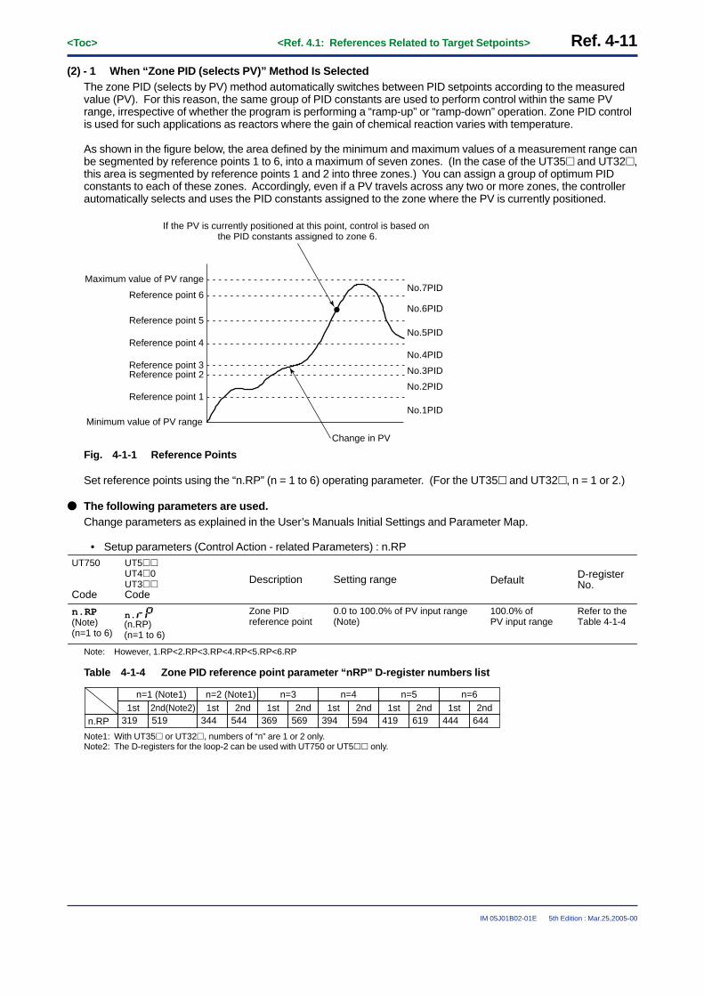
<Toc> <Ref. 4.1: References Related to Target Setpoints> Ref. 4-11
IM 05J01B02-01E 5th Edition : Mar.25,2005-00
(2) - 1 When “Zone PID (selects PV)” Method Is SelectedThe zone PID (selects by PV) method automatically switches between PID setpoints according to the measuredvalue (PV). For this reason, the same group of PID constants are used to perform control within the same PVrange, irrespective of whether the program is performing a “ramp-up” or “ramp-down” operation. Zone PID controlis used for such applications as reactors where the gain of chemical reaction varies with temperature.
As shown in the figure below, the area defined by the minimum and maximum values of a measurement range canbe segmented by reference points 1 to 6, into a maximum of seven zones. (In the case of the UT35� and UT32�,this area is segmented by reference points 1 and 2 into three zones.) You can assign a group of optimum PIDconstants to each of these zones. Accordingly, even if a PV travels across any two or more zones, the controllerautomatically selects and uses the PID constants assigned to the zone where the PV is currently positioned.
No.1PIDMinimum value of PV range
Maximum value of PV range
Reference point 1
Reference point 2Reference point 3
Reference point 4
Reference point 5
Reference point 6
No.2PID
No.3PID
No.4PID
No.5PID
No.6PID
No.7PID
Change in PV
If the PV is currently positioned at this point, control is based on the PID constants assigned to zone 6.
Fig. 4-1-1 Reference Points
Set reference points using the “n.RP” (n = 1 to 6) operating parameter. (For the UT35� and UT32�, n = 1 or 2.)
● The following parameters are used.Change parameters as explained in the User’s Manuals Initial Settings and Parameter Map.
• Setup parameters (Control Action - related Parameters) : n.RP
Description Setting range Default D-register No.
n.RP(Note)(n=1 to 6)
Zone PID reference point
0.0 to 100.0% of PV input range(Note)
100.0% of PV input range
Refer to the Table 4-1-4
UT750
Code
UT5��UT4�0UT3��Code
n.(n.RP)(n=1 to 6)
Note: However, 1.RP<2.RP<3.RP<4.RP<5.RP<6.RP
Table 4-1-4 Zone PID reference point parameter “nRP” D-register numbers list
n=1 (Note1)1st
319n.RP2nd(Note2)519
n=2 (Note1)1st
3442nd
544
n=31st
3692nd
569
n=41st
3942nd
594 444 644
n=51st
4192nd
619
n=61st 2nd
Note1: With UT35� or UT32�, numbers of “n” are 1 or 2 only.Note2: The D-registers for the loop-2 can be used with UT750 or UT5�� only.

Ref. 4-12<Toc> <Ref. 4.1: References Related to Target Setpoints>
IM 05J01B02-01E 5th Edition : Mar.25,2005-00
Setting Hysteresis for Zone SwitchingIf you have selected the zone PID method, you can set hysteresis for zone switching.
To do this, use the “RYH” parameter. (The factory-set hysteresis is 0.5% of the PV input span.)
In the case of the UT750 and UT5��, the RYH parameter belongs to the same submenu [CTL] as the “ZON” and“n.RP” parameters discussed earlier.
If the model is UT4�0, this parameter belongs to setup parameters (related to control/operation). If the model isUT3��, hysteresis for zone switching is fixed at 0.5% of the PV input span.
● The following parameters are used.Change parameters as explained in the User’s Manuals Initial Settings and Parameter Map.
• Setup parameters (Control Action - related Parameters) : RHYUT750
Code
Description Setting range
469 (for loop-1)669 (for loop-2) (Note2)
0.5%
Default D-register No.
UT5��UT4�0
Code
RHY Zone switching hysteresis 0.0 to 100.0% of PV input range span(RHY)
Note1: UT35� or UT32� does not have a parameter for changing the value of Zone switching hysteresis. (The value is fixed to 0.5% of PV input range span.)Note2: The D-registers for the loop-2 can be used with UT750 or UT5�� only.
An example of the zone switching hysteresis is shown below.
No.1PID
Reference point 1RHY
PV
EOS (0.5%)
No.2PID No.1PID No.2PID
Fig. 4-1-2 Zone switching hysterisis
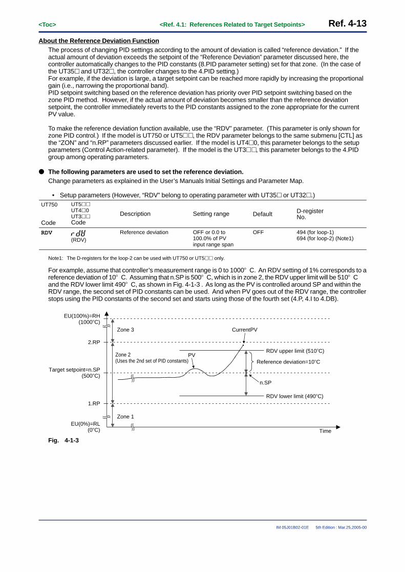
<Toc> <Ref. 4.1: References Related to Target Setpoints> Ref. 4-13
IM 05J01B02-01E 5th Edition : Mar.25,2005-00
About the Reference Deviation FunctionThe process of changing PID settings according to the amount of deviation is called “reference deviation.” If theactual amount of deviation exceeds the setpoint of the “Reference Deviation” parameter discussed here, thecontroller automatically changes to the PID constants (8.PID parameter setting) set for that zone. (In the case ofthe UT35� and UT32�, the controller changes to the 4.PID setting.)For example, if the deviation is large, a target setpoint can be reached more rapidly by increasing the proportionalgain (i.e., narrowing the proportional band).PID setpoint switching based on the reference deviation has priority over PID setpoint switching based on thezone PID method. However, if the actual amount of deviation becomes smaller than the reference deviationsetpoint, the controller immediately reverts to the PID constants assigned to the zone appropriate for the currentPV value.
To make the reference deviation function available, use the “RDV” parameter. (This parameter is only shown forzone PID control.) If the model is UT750 or UT5��, the RDV parameter belongs to the same submenu [CTL] asthe “ZON” and “n.RP” parameters discussed earlier. If the model is UT4�0, this parameter belongs to the setupparameters (Control Action-related parameter). If the model is the UT3��, this parameter belongs to the 4.PIDgroup among operating parameters.
● The following parameters are used to set the reference deviation.Change parameters as explained in the User’s Manuals Initial Settings and Parameter Map.
• Setup parameters (However, “RDV” belong to operating parameter with UT35� or UT32�.)UT750
Code
Description Setting range
494 (for loop-1)694 (for loop-2) (Note1)
OFF
Default D-register No.
UT5��UT4�0UT3��Code
RDV Reference deviation OFF or 0.0 to 100.0% of PV input range span
(RDV)
Note1: The D-registers for the loop-2 can be used with UT750 or UT5�� only.
For example, assume that controller’s measurement range is 0 to 1000� C. An RDV setting of 1% corresponds to areference deviation of 10� C. Assuming that n.SP is 500� C, which is in zone 2, the RDV upper limit will be 510� Cand the RDV lower limit 490� C, as shown in Fig. 4-1-3 . As long as the PV is controlled around SP and within theRDV range, the second set of PID constants can be used. And when PV goes out of the RDV range, the controllerstops using the PID constants of the second set and starts using those of the fourth set (4.P, 4.I to 4.DB).
EU(100%)=RH(1000�C)
Target setpoint = n.SP(500�C)
EU(0%)=RL(0�C)
2.RP
1.RP
Zone 1
Zone 3 Current PV
RDV upper limit (510�C)
RDV lower limit (490�C)
Time
Reference deviation = 10�C
n.SP
PVZone 2(Uses the 2nd set of PID constants)
Fig. 4-1-3

Ref. 4-14<Toc> <Ref. 4.1: References Related to Target Setpoints>
IM 05J01B02-01E 5th Edition : Mar.25,2005-00
(2) - 2 When “Target Setpoint (SP) number selection” Method Is SelectedIn the SP number selection method, the operators of the controller can switch between the eight target setpointsas necessary (In the case of the UT35� and UT32�, switch between the four SPs.). Switching is carried out bysetting the parameter SP.NO using key operation, or by using external DIS contact inputs.Switching of target setpoint is always possible. Once switched, the UPR (target setpoint ramp-up) or DNR (targetsetpoint ramp-down) function can be used to change the current setpoint. (See Ref.4.1(4).) When the targetsetpoint is switched, the controller performs control computation using the set of PID constants that correspond tothe currently selected target setpoint (1.SP, 2.SP, 3.SP, to 8SP).
Switched from 1.SP
to 3.SP
Switched from 3.SP
to 1.SP
Switched from 1.SP
to 2.SP
Increases according to UPR.
Time
Decreases according to DNR.
Increases according
to UPR.
1.SP
SP
(No.1PID)
3.SP
(No.3PID)
1.SP
(No.1PID)
2.SP
(No.2PID)
Fig. 4-1-4

<Toc> <Ref. 4.1: References Related to Target Setpoints> Ref. 4-15
IM 05J01B02-01E 5th Edition : Mar.25,2005-00
(2) - 3 When “Zone PID (selects by target setpoint)” Method Is Selected (For UT551 only)The Zone PID (selects by target setpoint) method automatically switches between PID setpoints according to thetarget setpoint.To use this function, segment the area defined by the minimum and maximum values of a measurement range byreference points 1 to 6, into a maximum of seven zones.For the reference point, see “(2)-1 When Zone PID (selects by PV) Method Is Selected.”The example where the area is segmented into five zones is shown below.When the target setpoint is changed from 100°C to 350°C, the target setpoint is between the reference points 2and 3. In this case, No.3PID is selected.Then when the target setpoint is changed from 350°C to 250°C, the target setpoint is between the reference points1 and 2. In this case, No.2PID is selected.Finally, when the target setpoint is changed from 250°C to 800°C, the target setpoint is between the referencepoints 4 and 5. In this case, No.5 PID is selected.
Maximum value of measurement range
Minimum value of measurement range
Reference point 4
PID No. to be selected
No.1 PID No.3 PID No.2 PID No.5 PID
(No.5 PID)
(No.4 PID)
(No.3 PID)
(No.2 PID)
(No.1 PID)
Time
Target setpoint is changed from 100 °C to 350 °C.
Target setpoint is changed from 350 °C to 250 °C.
Target setpoint is changed from 350 °C to 250 °C.
800 °C
Reference point 3
Reference point 2
350 °C
Reference point 1
250 °C
100 °C
SP
Target setpoint
Current setpoint
Fig. 4-1-5 Selecting a PID number by target setpoint

Ref. 4-16<Toc> <Ref. 4.1: References Related to Target Setpoints>
IM 05J01B02-01E 5th Edition : Mar.25,2005-00
(2) - 4 When “Selects by specified PID number” Method Is Selected (For UT551 only)In the PID number selection method, the operators of the controller can switch between the eight PID setpoints asnecessary.In this method, target setpoint is not in conjunction with PID setpoint and an arbitrary PID setpoint can be selected.On the other hand, in the Target setpoint (SP) number selection method, target setpoint is in conjunction with PIDsetpoint.Switching is carried out by setting the parameter P.NO using key operation, or by using external DIS contactinputs.For the switching by external contact input, see “Ref.3.1(3) Changing contact input functions for the UT550/UT551/UT551.”When the PID number is selected by external contact input, the PID number cannot be selected by key operationor communication.In the case of key operation and communication, the last selection is effective.Change parameter as explained in the User’s Manuals Initial Settings and Parameters.
• Setup parameters.
2251
UT551Code
PID No. selection(Note 1)
1 to 8(Note 2)(P.NO)
Description Setting range Default D-register No.
Note1: Displayed when the setup parameter ZON = 3.Note2: The setting range depends on the setup parameter GRP.

<Toc> <Ref. 4.1: References Related to Target Setpoints> Ref. 4-17
IM 05J01B02-01E 5th Edition : Mar.25,2005-00
<<Ref. 4-1: References Related to Target Setpoints>>Ref.4.1(3) Limiting Changes in Target Setpoints
The UT750, UT5�� and UT4�0 can be operated using the remote target setpoints that they receive externally.In this case, the control output may change suddenly when the controller switches from remote-mode operation tolocal-mode operation (operation based on the controller’s own internal target setpoints). To avoid this problem,the UT750, UT5�� and UT4�0 are designed to allow the control output to keep track of the PV so it can smoothlyswitch from the remote target setpoint to the local target setpoint. (The UT35� and UT32� do not have remotecontrol capabilities, so this feature is not available.)
Selects the use of the SP tracking function. Specify OFF to disable the function, or ON to enable the function.
Time R-L mode change R-L mode change
Time
● SP tracking enabled ● SP tracking enabled
PV
PV
Local SP Local SP
Fig. 4-1-5 SP Tracking
● The following parameters are used to select ON or OFF of SP tracking function.Change parameters as explained in the User’s Manuals Initial Settings and Parameter Map.
• Setup parametersUT750
Code
Description Setting range
904 (for loop-1)942 (for loop-2) (Note1)
ON
Default D-register No.
UT5��UT4�0
Code
SPT SP tracking selection OFF or ON
(SPT)
Note1: The D-registers for the loop-2 can be used with UT750 or UT5�� only.

Ref. 4-18<Toc> <Ref. 4.1: References Related to Target Setpoints>
IM 05J01B02-01E 5th Edition : Mar.25,2005-00
<<Ref. 4.1: Reference Related to Target setpoint>>Ref.4.1(4) Setting ramp grades when switching between target setpoints
This function can be used with UT750, UT5��, UT4�0 or UT3��.
To prevent the target setpoint (SP) from changing suddenly or to change it at a constant rate, the ramp-up (UPR)and ramp-down (DNR) rates for SP can be set. This function is used in the following four events.
(1) SP is changed. (e.g., when 1.SP is changed from 100�C to 150�C)(2) SP number (SP.NO) is switched. (e.g., when switched from 1.SP to 3.SP)
Note: This only applies during SP number selection.(3) Power is turned on (or power has recovered). (Note).(4) Switched from MAN mode to AUTO mode. (Note).
Note: SP changes at the specified ramp rate starting from the current PV value toward the original target setpoint.
Old SP
SP change Time SP No. switching
Power-on or MAN to AUTO switching
Time Time
Old SPNew SP PV
New SP SP
Specified ramp rate
Specified ramp rate Specified
ramp rate
Inst
rum
ent
rang
e
(3) When power is turned on (or power has recovered)(4) When switched from MAN to AUTO
(2) When SP number (SP.NO) is switched
(1) When SP is changed
Fig. 4-1-6
TIP
The time unit of the ramp rate can be set to either an hour or minute, using parameter “TMU”.
Example of Setting the SP Ramp-up Rate (UPR)
Fig. 4-1-7 shows an example of how to et the SP ramp-up rate (UPR).SPs are set as 1.SP=500� C and 2.SP=640� C. The controller first operates using 1.SP, and later switches to 2.SP,as the SP value increases at the specified rate. In this example, the temperature difference between 2.SP and1.SP is 140� C, which needs to be changed within two minutes. To achieve this operation, UPR is set at 70 (� C/minute).
70�C/min.UPR = 140/2 = 70 (�C/min.)
Heat up for2 minutes
2.SP1.SP
2.SP = 640�C
1.SP=500�C
SP switching
Temperature difference of
140�C
Fig. 4-1-7

<Toc> <Ref. 4.1: References Related to Target Setpoints> Ref. 4-19
IM 05J01B02-01E 5th Edition : Mar.25,2005-00
UPR = =Time (min.) (Note)
Temperature difference (�C)= 70 (�C/min.)
2140
Note: The time unit of the ramp rate can be set to either an hour or minute, using parameter TMU (time unit for ramp-rate setting).
● The following parameters are used.Change parameters as explained in the User’s Manuals Initial Settings and Parameter Map.
[ Ramp-rate Setting Parameters]• Operating parameters (Operation-related Parameters) : UPR, DNR
UT750
Code
Description Setting range
245(for loop-1)275(for loop-2) (Note1)
OFF
Default D-register No.
UT5��UT4�0UT3��Code
UPR Setpoint ramp-up rate(UPR)
OFF or (0.0%+1digit) to 100.0% of PV input range span
246(for loop-1)276(for loop-2) (Note1)
OFFDNR Setpoint ramp-down rate(DNR)
OFF or (0.0%+1digit) to 100.0% of PV input range span
Note1: The D-registers for the loop-2 can not be used with UT4�0 or UT3�0 .
[ Ramp-rate Time Unit Setting Parameter]• Setup parameters (Target Setpoint-related Parameter) : TMU
UT750
Code
Description Setting range
904(for loop-1)944(for loop-2) (Note2)
HOUR
Default D-register No.
UT5��UT4�0UT3��Code
TMU Ramp-rate time unit setting
HOUR or MIN (Note1)HOUR : Denotes “per hour”MIN : Denotes “per minute”
(TMU)
Note1: With UT35� or UT32�, the setting value is “0” or “1”. “0” denotes “per hour” and “1” denotes “per minute”.Note2: The D-registers for the loop-2 can not be used with UT4�0 or UT3�� .

Blank Page

<Toc> <Ref. 5.1: References Related to Segment Operation> Ref. 5-1
IM 05J01B02-01E 5th Edition : Mar.25,2005-00
Ref.5.1: References Related to Segment Operation
IMPORTANT: Applicable models of this section
UP750 UP550 UP35� UT750 UT5�� UT4�0 UT3��
UP750-�� UP550-�� UP35�-�� None None None None
Note: Some of the functions below are not available on certain models. For more information, see those sections.
This section contains reference information on the following aspects of segment operation programmed with UPSeries program controllers.Refer to this information and change parameters only if necessary.
(1) Selecting Segment time between Time and Ramp time(2) Selecting PID Control between Zone and Segment
<<Ref. 5.1: Reference Related to Segment Operation>>Ref.5.1(1) Selecting Segment time between Time and Ramp time
Segment time selection is available for the UP750, UP550 and UP35�.Segment time can be selected between the two criteria below. Selection is made with the “SGT” setup parameter.
• Segment time (Factory-set default)• Segment ramp time
The selected time criterion is applied to all segments in the program pattern.
CAUTIONChanging segment time criterion will erase the entire program pattern.

Ref. 5-2<Toc> <Ref. 5.1: References Related to Segment Operation>
IM 05J01B02-01E 5th Edition : Mar.25,2005-00
● The following parameters are used.• Setup parameters (Target Setpoint-related Parameters): SEG.T
UP750UP550
Code
SEG.T
UP35�
Code
Description Setting Range Default D-register No.
Segment setting method
0: Programming by setting segment times
1: Programming by setting segment ramps
0 905
(SEG.T)
Depending on the selected segment time criterion, the above “SEG.T” parameter changes the content of thesegment time in the program pattern as follows. (See Page Ref. 5-3 or Page Ref. 5-4)
• When SEG.T = 0, segment time is displayed as “TIME”.• When SEG.T = 1, segment ramp time is displayed as “TM.RT”.
■ Setting the Required Parameters
Carry out the operation shown below.(UP750/UP550 parameter setting way is shown in the following example.)
Here we explain how to display the parameter setting display and to change the parameter values. Beforecarrying out these operations be sure to refer to the User’s Manuals Initial Settings and Parameter Map of thecontroller.The parameter map is very helpful in finding the path to the setting display for a particular parameter.
1: Referring to the User’s Manual above,display the setup parameter main menu[PARA].Then, display the submenu [SP].
2 : Press the SET/ENT key three times todisplay the parameter “SEG.T”.Adjust the parameter value (to 0 or 1)using the / keys, then pressthe SET/ENT key to Register it.For example, when you want to select“Programming by setting segmentramps”, adjust the parameter value to“1” and register it by pressing the SET/ENT
key.
PARA
SP ALM CTL
SETSET SET
OK
SET DISP
UP750, UP550 Parameters Map
Pass word
SPL2
PT2.GSEG.TTMUSPT
SPH2SPL1SPH1PNC
UPMD
ZON
MOD1MOD2
OPR1OPR2
RDV
R.TMR.MD
PEH4PEH3PEH2PEH1
PEH7PEH6PEH5
AMD
PEH8AL1AL2AL3AL4HY1HY2HY3HY4
CMLP CONF
DISP
Operating Display
AR1AR2
6.RP
2.RP3.RP
GRP1.RP
RHY
4.RP5.RP
MainMenu
SubMenu
“SEG.T”
This completes the setting operation. If other settings are unnecessary, return to operating display.

<Toc> <Ref. 5.1: References Related to Segment Operation> Ref. 5-3
IM 05J01B02-01E 5th Edition : Mar.25,2005-00
■ When segment time is selected (Factory-set default)
The segment time criterion bases segment operation on the “TSP1” target setpoint (Note) and the “TIME” seg-ment time.The target setpoint is the control target to be attained at segment end, whereas the segment time is the timeduration from the start of that segment to the end.Note: TSP2 can also be used if using dual-loop control with the UP750. With the UP35�, the n.SP1 - n.SPA (n is either parameter No. 1 or 2)
parameters are used.
PV
TIME
Segment noperation
Target setpoint: TSP1 (or TSP2)
Time
n=1 to 99
Target setpoint of last segment (Start target setpoint if program just started)
Segment time(The unit of time is determined by “TMU”.)
Fig. 5-1-1 Segment operation when segment time is selected
● The following parameters are used.Change parameters as explained in the User’s Manuals Initial Settings, Programming and Parameter Maps.
• Program Parameters: TSP1, TSP2, TIME
UP750UP550
Code
UP35�
Code
Description Setting Range
0.0 to 100.0% of PV input range
0.0% of PV input range
Default B-register No.[UP750, UP550 only]
111
112
113Time-set segment time [“TIME” is displayed only when “SEG.T” is set to “0”]
– (unregistered) or00.00 to 99.59[“Hour, minute” or “Minute, second”]
– (unregistered)
TSP2 (Note1) Target SP (for 2nd loop)
TSP1 Target setpoint of each segment
TIME
n.
n.to(n.SP1 to n.SPA)(n: 1 or 2)
(Note1)
n.
n.to(n.TM1 to n.TMA)
Note1: The parameter “TSP2” can be displayed only when the “PT2.G” parameter is set to ON.
• Setup Parameter (Target Setpoint-related Parameter): TMU
UP750UP550
Code
TMU
UP35�
Code
Description Setting Range Default D-register No.
Program time unit hh:mm: “Hour, minute”mm:ss: “Minute, second”
hh:mm 904
(TMU)

Ref. 5-4<Toc> <Ref. 5.1: References Related to Segment Operation>
IM 05J01B02-01E 5th Edition : Mar.25,2005-00
■ When segment ramp time is selected
The segment ramp time criterion bases segment operation on the “TSP1” target setpoint (Note) and the “TM.RT”segment ramp time.Ramp time in segment ramp-up or ramp-down is expressed as an amount of change (between target setpoints)per hour or per minute.The unit of time is selected with “TMU”. When segment is set for soaking at a constant target setpoint, ramp timeexpresses the time duration of the segment.Note: TSP2 can also be used if using dual-loop control with the UP750. With the UP35�, the n.SP1 - n.SPA (n is either parameter No. 1 or 2)
parameters are used.
● The following parameters are used.Change parameters as explained in the User’s Manuals Initial Settings, Programming and Parameter Maps.
• Program Parameters: TSP1, TSP2, TM.RT
UP750UP550
Code
UP35�
Code
Description Setting range
0.0 to 100.0% of PV input range
0.0% of PV input range
Default B-register No.[UP750, UP550 only]
111
112
114Ramp-set segment time [“TM.RT” is displayed only when “SEG.T” is set to “1”.]
1. For ramp segments:– (unregistered) or 0.0 to 100.0% of PV input range span per hour or minute.
2. For soak segments:– (unregistered) or 0.00 to 99.59 [“Hour, minute” or “Minute, second”]
– (unregistered)
TSP2 (Note1) Target SP (for 2nd loop)
TSP1 Target setpoint of each segment
TM.RT
n.
n.to(n.SP1 to n.SPA)(n: 1 or 2)
(Note1)
n.
n.to(n.TM1 to n.TMA)
Note1: The parameter “TSP2” can be displayed only when the “PT2.G” parameter is set to ON.
• Setup Parameter (Target Setpoint-related Parameter): TMU
UP750UP550
Code
TMU
UP35�
Code
Description Setting range Default D-register No.
Program time unit hh:mm: “Hour, minute”mm:ss: “Minute, second”
hh:mm 904
(TMU)

<Toc> <Ref. 5.1: References Related to Segment Operation> Ref. 5-5
IM 05J01B02-01E 5th Edition : Mar.25,2005-00
● Segment time during ramp-up operationsWhen the target setpoint of the current segment is higher than that of the last segment, ramp-up operations areperformed for the current segment.During ramp-up, the amount of change (between target setpoints) per hour or per minute is set with the ramp timeparameter “TM.RM”.
PV
TM.RT
Segment noperation
Target setpoint: TSP1 (or TSP2)
Time
n=1 to 99
TM.RT
Target setpoint of last segment(Start target setpoint if program just started) Segment ramp time
(The unit of time is set with “TMU”.)
“TM.RT” sets the amount of changein this area per hour or per minute.
Fig. 5-1-2 Segment time during ramp-up operations
● Segment time during ramp-down operationsWhen the target setpoint of the current segment is lower than that of the last segment, ramp-down operations areperformed for the current segment.During ramp-down, the amount of change (between target setpoints) per hour or per minute is set with the ramptime parameter “TM.RM”.
PV
TM.RT
Segment noperation
Target setpoint: TSP1 (or TSP2)
Time
n=1 to 99Target setpoint of last segment
(Start target setpoint if program just started)
Fig. 5-1-3 Segment time during ramp-down operations

Ref. 5-6<Toc> <Ref. 5.1: References Related to Segment Operation>
IM 05J01B02-01E 5th Edition : Mar.25,2005-00
● Segment time during soak operationsWhen the target setpoint of the current segment is the same as that of the last segment, soak operations areperformed for the current segment.The time duration of the soak segment is set with the ramp time parameter “TM.RM”.
PV
TM.RT
Segment noperation
Target setpoint: TSP1 (or TSP2)
Time
n=1 to 99
Target setpoint of last segment(Start target setpoint if program just started)
Fig. 5-1-4 Segment time during soak operations

<Toc> <Ref. 5.1: References Related to Segment Operation> Ref. 5-7
IM 05J01B02-01E 5th Edition : Mar.25,2005-00
<<Ref. 5.1: Reference Related to Segment Operation>>Ref.5.1(2) Selecting PID control between Zone and Segment
With the UP750 and UP550 program controllers, PID control can be selected from the two criteria below. Selectionis made with the “ZON” program parameter. (With the UP350, only zone PID control is available.)
• Zone PID (Factory-set default)• Segment PID
● The following parameters are used.Change parameters as explained in the User’s Manuals Initial Settings and Parameter Maps.
• Setup Parameter (Control Action-related parameter): ZON
UP750UP550
Code
Description Setting range
9291
Default D-register No.
ZON Zone PID selection 0: Segment PID1: Zone PID
Note: With UP750, this parameter is used with the 1st and 2nd loop in common.
■ Setting the Required Parameters
Carry out the operation shown below.(UP750/UP550 parameter setting way is shown in the following example.)
Here we explain how to display the parameter setting display and to change the parameter values. Beforecarrying out these operations be sure to refer to the User’s Manuals Initial Settings and Parameter Map of thecontroller.The parameter map is very helpful in finding the path to the setting display for a particular parameter.
1: Referring to the User’s Manual above,display the setup parameter main menu[PARA].Then, display the submenu [CTL].
2 : Press the SET/ENT key time and again todisplay the parameter “ZON”.Adjust the parameter value (to 0 or 1)using the / keys, then press the
SET/ENT key to Register it.For example, when you want to select“Segment PID”, adjust the parameter valueto “0” and register it by pressing the SET/ENT
key.
PARA
SP ALM CTL
SET
OK
SET DISP
UP750, UP550 Parameters Map
PT2.GSEG.TTMUSPT
UPMD
ZON
MOD1MOD2
OPR1OPR2
R.TMR.MD
PEH4PEH3PEH2PEH1
PEH7PEH6PEH5
AMD
PEH8AL1AL2AL3AL4HY1HY2HY3HY4
CMLP CONF
DISP
AR1AR2
SPL2SPH2SPL1SPH1PNC
RDV
6.RP
2.RP3.RP
GRP1.RP
RHY
4.RP5.RP
SETSET
Pass word Operating display
MainMenu
SubMenu
“ZON”
This completes the setting operation. If other settings are unnecessary, return to operating display.
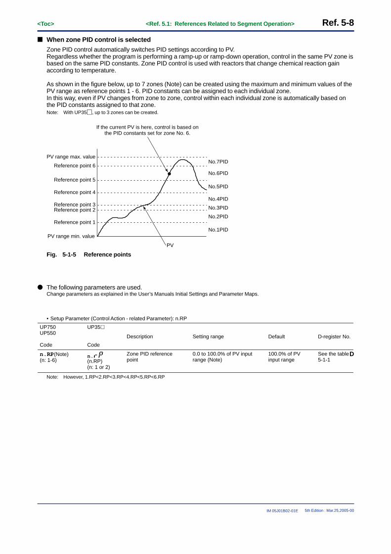
Ref. 5-8<Toc> <Ref. 5.1: References Related to Segment Operation>
IM 05J01B02-01E 5th Edition : Mar.25,2005-00
■ When zone PID control is selected
Zone PID control automatically switches PID settings according to PV.Regardless whether the program is performing a ramp-up or ramp-down operation, control in the same PV zone isbased on the same PID constants. Zone PID control is used with reactors that change chemical reaction gainaccording to temperature.
As shown in the figure below, up to 7 zones (Note) can be created using the maximum and minimum values of thePV range as reference points 1 - 6. PID constants can be assigned to each individual zone.In this way, even if PV changes from zone to zone, control within each individual zone is automatically based onthe PID constants assigned to that zone.Note: With UP35�, up to 3 zones can be created.
No.1PIDPV range min. value
PV range max. value
Reference point 1
Reference point 2Reference point 3
Reference point 4
Reference point 5
Reference point 6
No.2PID
No.3PID
No.4PID
No.5PID
No.6PID
No.7PID
PV
If the current PV is here, control is based onthe PID constants set for zone No. 6.
Fig. 5-1-5 Reference points
● The following parameters are used.Change parameters as explained in the User’s Manuals Initial Settings and Parameter Maps.
• Setup Parameter (Control Action - related Parameter): n.RP
UP35�
Code
Description Setting range Default D-register No.
n.RP(Note)(n: 1-6)
Zone PID reference point
0.0 to 100.0% of PV input range (Note)
100.0% of PV input range
See the table 5-1-1
UP750UP550
Code
n.(n.RP)(n: 1 or 2)
D
Note: However, 1.RP<2.RP<3.RP<4.RP<5.RP<6.RP

<Toc> <Ref. 5.1: References Related to Segment Operation> Ref. 5-9
IM 05J01B02-01E 5th Edition : Mar.25,2005-00
Table 5-1-1 PID-related parameter D-register numbers list (1st : for loop-1, 2nd : for loop-2, UP750 only)
n=11st
306307308309310311312313314315316317318319320321
n.Pn.In.Dn.OHn.OLn.MRn.Hn.DRn.Pcn.Icn.Dcn.Hcn.DBn.RPn.POn.Oc
2nd506507508509510511512513514515516517518519520521
n=21st
331332333334335336337338339340341342343344345346
2nd531532533534535536537538539540541542543544545546
n=31st
356357358359360361362363364365366367368369370371
2nd556557558559560561562563564565566567568569570571
n=41st
381382383384385386387388389390391392393394395396
2nd581582583584585586587588589590591592593594595596
431432433434435436437438439440441442443444445446
631632633634635636637638639640641642643644645646
456457458459460461462463464465466467468
–470471
656657658659660661662663664665666667668
–670671
481482483484485486487488489490491492493
–495496
681682683684685686687688689690691692693
–695696
n=51st
406407408409410411412413414415416417418419420421
2nd606607608609610611612613614615616617618619620621
n=61st 2nd
n=71st 2nd
n=81st 2nd
See this column for each D-register number of “n.RP” parameters.(For example, the D-register number of 1.RP is 319.)
Note: UP35� has only 1.RP and 2.RP (D-register number of 1.RP is 319 and it of 2.RP is 344.)
■ When segment PID control is selected
Segment PID control automatically switches PID settings to those set for each segment of the program pattern (inprogrammed operations).It is best used when wanting to control the same PV zone to different PID constants during ramp-up and ramp-down.The following example shows how PID settings change in segment PID control.
PV
No.2PID
SEG1 SEG2 SEG3 SEG4 SEG5 SEG6 SEG7
No.1PID No.3PID
1000
500
0
If the program is currently at segmentNo. 5, control is based on the PIDconstants set for PID No. 1.
Fig. 5-1-6 Segment PID control example
PID No. is set with the “PID” program parameter when setting up the program pattern for each segment. Forexample, if “PID” is set to “2” for a segment, its control will be based on PID No. 2 that is set with another operatingparameter.
● The following parameters are used.Change parameters as explained in the User’s Manuals “Programming” and “Parameter Maps”.
• Program Parameter: PID
UP750UP550
Code
Description Setting range
1 to 8 (Note2) 1
Default
PID (Note1) Segment PID group number
B-register No.[UP750, UP550 only]
115
Note1: The controller uses the 1st group of PID constants when the segment PID group number is larger than the PID group number (setupparameter GRP).
Note2: With UP750, this parameter is used with the 1st and 2nd loop in common.

Ref. 5-10<Toc> <Ref. 5.2: References Related to Program Setup>
IM 05J01B02-01E 5th Edition : Mar.25,2005-00
Ref.5.2: References Related to Program Setup
IMPORTANT: Applicable models of this sectionUP750 UP550 UP35� UT750 UT5�� UT4�0 UT3��
UP750-�� UP550-�� UP35�-�� None None None None
Note: Some of the functions below are not available on certain models. For more information, see those sections.
This section contains reference information on the following aspects of program setup.Refer to this information and change parameters only if necessary.
(1) Selecting Program Start Condition(2) Using the Delayed Start Timer for Programmed Operations(3) Selecting Segment-end condition(4) Using the Wait Function(5) Using the Hold Function (Changing Segment Setpoints in Hold Status)(6) Using the Repeat Functions(7) Using the Advance Functions(8) Signal Output at Program end(9) Operation in Local Mode (with Constant Target Setpoint)
<<Ref. 5.2: References Related to Program Setup>>Ref.5.2(1) Selecting Program Start Condition
The program start condition can be selected with the UP750, UP550 and UP35�.It bases operation starting on the “STC” program parameter (Note1) and the “SSP1” start target setpoint (Note2).“STC” can be selected from the 4 criteria (Note3) below.To begin with, select the operation start condition with this “STC” program parameter.
• Starting operation at start target setpoint (Factory-set default)• Ramp-prioritized PV1 start• Time-prioritized PV start• Ramp-prioritized PV2 start (Only for UP750, Dual loop control or Temperature and humidity control)
Note1: The n.STC (n is either pattern No. 1 or 2) is used with the UP350.Note2: SSP2 can also be used when the “PT2.G” setup parameter is “ON” with the UP750.
With the UP35�, the n.SSP (n is either pattern No. 1 or 2) parameter is used.Note3: With single loop controllers, three operation start conditions are available.
The wait and repeat operations described later on can be used provided “STC” is set to “-1”.In this case, the previous start condition does not change.

<Toc> <Ref. 5.2: References Related to Program Setup> Ref. 5-11
IM 05J01B02-01E 5th Edition : Mar.25,2005-00
● The parameter used for setting the start code is as follows.
• Program Parameter (Parameters for setting the Conditions of Program Operation Startup): STC
UP750UP550
Code
UP35�
Code
Setting range
0: Starting operation at start target setpoint
1: Ramp-prioritized PV1 start2: Time-prioritized PV start3: Ramp-prioritized PV2 start
(Note1) (-1: Note2)
0
Default
13
B-register No.[UP750, UP550 only]
STC
Description
Start Code(Start condition)
n.(n.STC)
Note1: Only for UP750 (Dual-loop control or Temperature and humidity control).Note2: The wait and repeat operations described later on can be used provided “STC” is set to “-1”. UP35� can not be set “-1” to the “STC”
parameter.
■ Setting the required parameters
To set the start code, carry out the operation shown below.(Here, the setting procedure of UP750/UP550 is shown as an example.)
1: Refer to the “Parameter Map” and “Program Parameter Map” in the user’s Manual.First, display the operating parameter main menu [PROG], then press the SET/ENT key to display the programparameter setting display. (Submenu [LOC] will be displayed.)
2: Press the / keys to display thesubmenu [PRG] .And then press the SET/ENT key to showthe “PTN” parameter setting display.
3: Perform the key operation following theparameter map to show the “STC”parameter setting display for therequired program pattern number.
4: Adjust the “STC” parameter value usingthe / keys, then press the SET/ENT
key to register it.
SET
NO
LOC
PTN
TSP1
TM.RTTIMETSP2
YES
PRG EDIT
“PTN” = 1 to 300 (UP750), 1 to 30 (UP550)“SEG” = 1 to 99 (UP750, UP550)SEG
DISP
DISP
SETSET DISP
SET
PTN300PTN1
[UP750]
[UP550]
PTN30
Same asPTN1
0 1 2 99
PID
EVnONnOFFnTYnPEn
JC
TSP1
TM.RTTIMETSP2
PID
EVnONnOFFnTYnPEn
JC
TSP1
TM.RTTIMETSP2
PID
EVnONnOFFnTYnPEn
JC
RCYRSTREN
1.WZ1
1.WTM1.WZ2
SSP1
STCSSP2
2.WZ12.WZ22.WTM3.WZ1
3.WTM3.WZ2
4.WZ14.WZ24.WTM5.WZ15.WZ25.WTM
STC = -1
SET DISP
UP750, UP550 Parameter Map
Sub menu
Operating Parameter[PROG]
“STC”
The parameter setting operation for the start code is completed.Pressing the SET/ENT key at least 3 seconds to go back to the operating display.

Ref. 5-12<Toc> <Ref. 5.2: References Related to Program Setup>
IM 05J01B02-01E 5th Edition : Mar.25,2005-00
■ Starting operation at start target setpoint: STC = 0 (Factory-set default)
The start target setpoint is the target setpoint at which programmed operation starts.When selected as the start condition, the target setpoint can be changed from the start setpoint “SSPn (n = 1 or 2)”to the target setpoint “TSPn (n = 1 or 2) ”.This change is made totally independent of PV, using the (TSPn - SSPn)/TIME ramp. (Note)Note: When “SEG.T” is set to 1 (segment ramp time is selected), the ramp rate obey the “TM.RT” setting value. See Ref.5.1(1).
PV
TIME
SEG1 SEG2
TSPn: Target setpointsSSPn: Start setpoint
Time
TSP2
SSP2
SSP1TSP1 Loop-1 program pattern
Loop-2 program pattern
Segment time(The unit of time is determined by “TMU” setup parameter.)
Fig. 5-2-1 Start operation at start target setpoint
● The parameter used to set the starting target setpoint is as follows.Change parameters as explained in the User’s Manuals programming and Parameter Maps.
• Program Parameter (Parameters for setting the Conditions of Program Operation Startup): SSP1, SSP2
UP750UP550
Code
UP35�
Code
Setting range
0.0 to 100.0% of PV input range
0.0% of PV input range
Default
SSP1SSP2 (Note1)
Description
Starting target setpoint
(Note2)(1.SSP or 2.SSP)
1112 (Note1)
B-register No.[UP750, UP550 only]
Note1: Only for UP750 (Dual-loop control or Temperature and humidity control).Note2: The “2.SSP” parameter is used for the 2’nd program pattern.

<Toc> <Ref. 5.2: References Related to Program Setup> Ref. 5-13
IM 05J01B02-01E 5th Edition : Mar.25,2005-00
■ Ramp-prioritized PV start: STC = 1
(This section explains about Ramp-prioritized PV2 start, too.)
With Ramp-prioritized PV start, operation start is triggered by primary loop PV (PV1) or secondary loop PV (PV2).The loop not selected as the start condition (PV2 if PV1 was selected) will start as specified by the PV startcondition in the pattern. Examples of PV1 ramp start and PV2 ramp start are as follows.
(1) Example of a soak segment for segment No. 2 of the primary loopWhen ramp-prioritized PV1 start is the selected start condition, the primary loop ramp is the start trigger.The primary loop contains points C1, D1 and E1. (PV at those points will vary according to a - e.)The secondary loop program will start at the same time as the primary loop does. For example, if C1 is the se-lected start point for the primary loop program, C2 will be that for the secondary loop program.
PV
SEG1
A1
B1
D1
E1
B2
C1
A2
C2
E2D2
SEG2 SEG3 SEG4 SEG5Time
a
b
c
d
e
Loop-2 program pattern
Loop-1 program pattern
Fig. 5-2-2 Example of a soak segment for segment No. 2 of the primary loop
Program start point is determined by the primary loop PV as follows. Try to understand the relationship of a - e toprogram start points C1, D1 and E1 in the above figure.
PV at program operation start
a
b
c
d
e
The primary loop’s program operation start points
C1
C1
C1
D1
E1 (Start SP)
The secondary loop’s program operation start points
C2
C2
C2
D2
E2 (Start SP)

Ref. 5-14<Toc> <Ref. 5.2: References Related to Program Setup>
IM 05J01B02-01E 5th Edition : Mar.25,2005-00
(2) Example of a soak segment for segment No. 3 of the secondary loopWhen ramp-prioritized PV2 start is the selected start condition, the secondary loop ramp is the start trigger.The secondary loop contains points A2 to E2. PV at those points will vary according to a - e.The primary loop program will start at the same time as the secondary loop does. For example, if A2 is the se-lected start point for the secondary loop program, A1 will be that for the primary loop program.
PV
SEG1
A1B1
D1E2
B2
C1
A2
C2
E1
D2
SEG2 SEG3 SEG4Time
Loop-1 program pattern
Loop-2 program pattern
a
b
c
d
e
Fig. 5-2-3 Example of a soak segment for segment No.3 of the secondary loop
PV
SEG1
A1B1
D1E2
B2
C1
A2
C2
E1
D2
SEG2 SEG3 SEG4Time
Loop-2 program pattern
Loop-1 program pattern
a
b
c
d
e
Fig. 5-2-4 Example of no soak segment in secondary loop
Program start point is determined by the secondary loop PV as follows. Try to understand the relationship of a - eto program start points A2 - E2 in the above figure.
PV at program operation start
a
b
c
d
e
The secondary loop’s program operation start points
A2
B2
C2
D2
E2 (Start SP)
The primary loop’s program operation start points
A1
B1
C1
D1
E1 (Start SP)

<Toc> <Ref. 5.2: References Related to Program Setup> Ref. 5-15
IM 05J01B02-01E 5th Edition : Mar.25,2005-00
(3) Example of programs with only ramp-up segmentsWhen Ramp-prioritized PV1 start is the selected start condition, the primary loop ramp is the start trigger.The primary loop contains points B1 to E1. PV at those points will vary according to a - e. When the PV is at “a”,program operation can not be started.The secondary loop program will start at the same time as the primary loop does. For example, if B1 is the se-lected start point for the primary loop program, B2 will be that for the secondary loop program.
PV
SEG1
A2B2
D2E1
B1
C2
A1
C1
E2
D1
SEG2Time
a
b
c
d
e
Loop-1 program pattern
Loop-2 program pattern
Fig. 5-2-5 Example of all segments in primary loop are “ramp”.
Program start point is determined by the primary loop PV as follows. Try to understand the relationship of a - e toprogram start points A1 - E1 in the above figure.
PV at program operation start
a
b
c
d
e
The primary loop’s program operation start points
Program operation can not be started (A1)
B1
C1
D1
E1 (Start SP)
The secondary loop’s program operation start points
Program operation can not be started (A2)
B2
C2
D2
E2 (Start SP)

Ref. 5-16<Toc> <Ref. 5.2: References Related to Program Setup>
IM 05J01B02-01E 5th Edition : Mar.25,2005-00
■ Time-prioritized PV start: STC = 2
With Time-prioritized PV starts, operation start is triggered by segment time 1, which sets the time from the PV atprogram start to the target setpoint of segment No. 1.The segment ramps in the figure below are determined by the “TIME” segment time.In this case, starting applies to both PV1 and PV2. An example of PV time start is as follows.
Ramp = (Target setpoint - PV)/Segment time
(1) Example of a soak segment for segment No. 2 of the primary loopThe start point of primary loop program will be a point a - e. Because the secondary loop program will start at thesame point as the primary loop does, it will start at a point a2 - e2.
PV
SEG1
TSP1
TSP2
TSPn: Target setpoint of loop-n (n: 1 or 2)
C2
C1
SEG2 SEG3 SEG4 SEG5Time
C1
C1
C1
C1
Loop-2 program pattern
Loop-1 program pattern
a
b
c
d
e
a2
b2
c2
d2
e2
Fig. 5-2-6 Example of a soak segment for segment No.2
Program start point is determined by the primary loop PV. The primary loop starts at PV1, while the secondaryloop starts at PV2.
PV at program operation start
a
b
c
d
e
The primary loop’s program operation start points
a
b
c
d
e
The secondary loop’s program operation start points
a2
b2
c2
d2
e2

<Toc> <Ref. 5.2: References Related to Program Setup> Ref. 5-17
IM 05J01B02-01E 5th Edition : Mar.25,2005-00
<<Ref. 5.2: References Related to Program Setup>>Ref.5.2(2) Using the Delayed Start Timer for Programmed Operation
The delayed start timer can be used with the UP750 and UP550.
It sets the time delay from when the program start operation is performed (pressing the RUN key, etc.) to whenoperation actually starts.When the secondary loop is used, the delay set here is used with both the primary and secondary loops.
● The parameter used for setting the start timer for program operation is as follows.Change parameters as explained in the User’s Manuals Initial Settings and Parameter Map.
• Operating Parameter (Operation-related Parameter): S.TM
UP750UP550
Code
Setting range
00.00 to 99.59 (“hour, minute” or “minute, second”) (Note1)
00.00
Default
253
D-register No.
S.TM
Description
Starting time of program pattern operation
Note1: The unit of the time (“hour, minute” or “minute, second”) is set by “TMU” setup parameter.
PV
Pressing the key
Time
The time set in“S.TM” is elapsed.
program operation start!
SP
The program operationis not started before
the time set in“S.TM” is elapsed.
RUN
Fig. 5-2-7 Program start operation when the time delay is set.

Ref. 5-18<Toc> <Ref. 5.2: References Related to Program Setup>
IM 05J01B02-01E 5th Edition : Mar.25,2005-00
<<Ref. 5.2: References Related to Program Setup>>Ref.5.2(3) Selecting Segment-end Condition
Use the program parameter “JC” to specify the program segment-end conditions.However, the program parameter setting functions for the UP750 and UP550 differ from those for the UP35�.First, the program parameter setting functions for the UP750 and UP550 are described here.(For the UP35�, refer to Ref. 5-22 later in this manual. Use either one to meet your selected model.)
[1] For the UP750 and UP550
Segment end condition can be set for each segment. End condition can be set so that the program advancesautomatically to the next segment.
● The following parameters are used herein:To change the parameter values, consult the Program Setup or Parameter Map in the appropriate user manuals provided separately.
• Program Parameter (Junction Code Parameter JC)
UP750UP550
Code
Description Setting range
0: Switching forContinuation
1: Hold-on switching2: Local-mode end
11 to 15: Wait during switching21 to 25: Wait within a segment
intervalINSERT: Allows a segment to
be added.DELETE: Allows a specified
segment to be deleted.
Default
JC Junction code set
(Note1)
(Note2)
1400
B-register No.[UP750, UP550 only]
Note1: For the wait features, see Ref.5.2(4) later in this manual.Note2: For the INSERT and DELETE functions, see also Ref. 5.3 later in this manual.

<Toc> <Ref. 5.2: References Related to Program Setup> Ref. 5-19
IM 05J01B02-01E 5th Edition : Mar.25,2005-00
■ Program continue: JC = 0 (Factory-set default)
If program continue (JC = 0) is selected as the segment end condition, the program advances to the next segmentand operation continues when the current segment ends. If it is set for the last segment in the program, theprogram stops (resets) at the end of that segment.At the end of the last segment, the start setpoint is taken as the target setpoint.An example of program continue being used as the segment end condition is as follows:
PV
TIMEn
SEG.n SEG.n+1
Time
n=1 to 98
TIMEn+1
Target setpoint of SEG.n
When SEG.n ends,the program advances tothe next segment (SEG.n + 1).
Fig. 5-2-8 Example of program continue as the segment end condition
■ Segment hold: JC = 1
When segment hold (JC = 1) is selected as the segment end condition, the program pauses (is placed on hold) atthe end of the current segment. While the program is on hold, the HOLD lamp is lit.The program is kept on hold until the hold state is released either by key input or external contact input. When thehold state is released for the last segment in the program, the program stops (resets). Executing the advancefunction while the program is on hold releases the hold state.(Ref.) Ref.5.2(7) Using the Advance Function
An example of segment hold being used as the segment end condition is as follows:
PV
TIMEn
SEG.n SEG.n+1
Time
n=1 to 98
TIMEn+1
During hold state
Program is held hereuntil the hold state is released.
The program pauses (goes on hold)at the end of a segment (SEG.n) for whichthe segment hold is set as the end condition.
Fig. 5-2-9 Example of segment hold as the segment end condition

Ref. 5-20<Toc> <Ref. 5.2: References Related to Program Setup>
IM 05J01B02-01E 5th Edition : Mar.25,2005-00
■ Local control: JC = 2
CAUTIONLocal control (JC = 2) can be set only for the last segment in the program pattern.If set for a segment in the middle of the program, the program will act as if program continue (JC = 0) were setas the segment end condition.
When local control (JC = 2) is selected as the segment end condition, the controller is in the local mode (constantsetpoint) at the end of the last segment in the program.
The target setpoint and event setpoint used here will vary, between (1) and (2) below, depending on whethersetpoint tracking is ON or OFF.Note: • To turn setpoint tracking ON/OFF, see the descriptions below.
• For PID control (zone or segment) selection, follow the description “Selecting PID Control between Zone and Segment.”• For local mode operation, see Ref.5.2(9) Operation in the Local (Constant Setpoint) Mode.
(1) When setpoint tracking is ONAt the end of the last segment in the program, the local (constant setpoint) mode is engaged. In this case, thetarget setpoint of the last segment is used as the target setpoint of the local mode. (See the figure below.)The local setpoint can be set in advance, but when setpoint tracking is ON, the target setpoint of the last segmentin the program will be tracked and used regardless of the local target setpoint.Even in the local mode, the current PV event continues to operate (but the time event is off). The contents that areset in advance as local events are changed to PV events when in local mode. If no PV events are set in theprogram, events set as local events in advance are all off.
PV
Time eventEVn
Last segmentSEG.n
Local setpoint
Even if a local setpoint is set in advance,constant control is engaged using the targetsetpoint of the last segment in the program asthe constant setpoint. To return operation to thepresetpoint, change the target setpoint by key input.
Time
n=1 to 99Programmedoperation
Local mode
Fig. 5-2-10 Local control as the segment end condition when setpoint tracking is ON

<Toc> <Ref. 5.2: References Related to Program Setup> Ref. 5-21
IM 05J01B02-01E 5th Edition : Mar.25,2005-00
(2) When setpoint tracking is OFFAt the end of the last segment in the program, the local (constant setpoint) mode is engaged. In this case, a localsetpoint that is set in advance is used as the target setpoint.In the local mode, PV events will operate according to the contents of the preset local events. The time eventsremain off.
PV
Time eventEVn
Last segmentSEG.n
Local setpoint(LSP1 or LSP2)
Time
n=1 to 99Programmedoperation
Local mode
At the end of the last segment in the program, constant controlis engaged using a local setpoint that is set in advance.
Fig. 5-2-11 Local control as the segment end condition when setpoint tracking is OFF
● To turn setpoint tracking ON/OFFSetpoint can be tracked with the UP750 and UP550.This function equalizes the local setpoint to the remote setpoint when switching from remote to local control. Thisprevents any sudden change in setpoint when control is switched from remote to local.
A brief expression regarding setpoint tracking is given below.
Switching from PRG to local modeTime
Switching from PRG to local modeTime
� Where the setpoint tracking features are provided: � Where the setpoint tracking features are not provided:
PV value
Localsetpoint
Programpattern
PV value
Localsetpoint
Programpattern
Fig. 5-2-12 Setpoint tracking operation
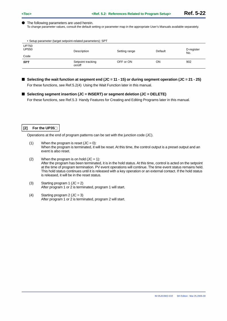
Ref. 5-22<Toc> <Ref. 5.2: References Related to Program Setup>
IM 05J01B02-01E 5th Edition : Mar.25,2005-00
● The following parameters are used herein.To change parameter values, consult the default setting or parameter map in the appropriate User’s Manuals available separately.
• Setup parameter (target setpoint-related parameters): SPT
UP750UP550
Code
Setting range
OFF or ON ON
Default
902
D-register No.
SPT
Description
Setpoint trackingon/off
■ Selecting the wait function at segment end (JC = 11 - 15) or during segment operation (JC = 21 - 25)
For these functions, see Ref.5.2(4) Using the Wait Function later in this manual.
■ Selecting segment insertion (JC = INSERT) or segment deletion (JC = DELETE)
For these functions, see Ref.5.3 Handy Features for Creating and Editing Programs later in this manual.
[2] For the UP35�
Operations at the end of program patterns can be set with the junction code (JC).
(1) When the program is reset (JC = 0):When the program is terminated, it will be reset. At this time, the control output is a preset output and anevent is also reset.
(2) When the program is on hold (JC = 1):After the program has been terminated, it is in the hold status. At this time, control is acted on the setpointat the time of program termination. PV event operations will continue. The time event status remains held.This hold status continues until it is released with a key operation or an external contact. If the hold statusis released, it will be in the reset status.
(3) Starting program 1 (JC = 2)After program 1 or 2 is terminated, program 1 will start.
(4) Starting program 2 (JC = 3)After program 1 or 2 is terminated, program 2 will start.

<Toc> <Ref. 5.2: References Related to Program Setup> Ref. 5-23
IM 05J01B02-01E 5th Edition : Mar.25,2005-00
With (3) and (4) above, an identical program pattern can be repeated or program patterns 1 and 2 can be linked.Figure 5-2-13 shows where program pattern 1 is repeated.This repetition will continue until program pattern 1 is stopped with a key operation, by external contacts or viacommunications.
SEG1 SEG2 SEG3 SEG4 SEG1SEG5 SEG5SEG2 SEG3 SEG4
Program 1 pattern
Time
Program 1 pattern
Start repetition
Fig. 5-2-13 Program pattern with program 1 repetition specified
● The following parameters are used herein:To change parameter values, consult the Program Setup or Parameter Map in the appropriate User’s Manual.
• Program parameter: 1.JC or 2.JC
UP35�
Code
Description Setting range
0: End of resetting1: End of hold2: Pattern 1 startup3: Pattern 2 startup
0
Default
Junction code 1orJunction code 2(Notes below)
(1.JC)or
(2.JC)
D-register No.
159
189
Note: Junction code 1 ( ) is for program pattern 1.
Junction code 2 ( ) is for program pattern 2.

Ref. 5-24<Toc> <Ref. 5.2: References Related to Program Setup>
IM 05J01B02-01E 5th Edition : Mar.25,2005-00
<<Ref. 5.2: References Related to Program Setup>>Ref.5.2(4) Using the Wait Function
The wait function temporarily pauses the program if PV cannot track the setpoint.Pausing the program stops the change in target setpoint. This gives PV a chance to track target setpoint. (See Fig.5-2-14.)The program is automatically resumed the moment that PV attains the target setpoint.
The wait functions for the UP750 and UP550 differ from those for the UP35�.First, the wait functions for the UP750 and UP550 are described here.(For the UP35�, refer to Ref. 5-28 later in this manual. Use either one to meet your selected model.)
[1] For the UP750 and UP550
With the UP750 and UP550, the wait function can be used in the following two ways.Selection in both cases is made with the “JC” program parameter.
• Program waits at segment end (Set “JC” to 11 - 15.)• Program waits in the middle of the segment (Set “JC” to 21 - 25.)
CAUTIONAs indicated in the following parameter tables, “n.WZ1” and “n.WTM” are factory set to OFF.Therefore, unless these parameters are changed, the wait function will remain OFF even if “JC” is set to 11 -15 or 21 - 25.
However, it is necessary to determine the following two wait conditions before selecting “JC”.
(1) Wait zone (Note1) ON/OFF and, if turning wait zone ON, the deviation range (measurement range direc-tion) of that wait zone.
(2) Wait time (Note2) ON/OFF and, if turning wait time ON, the duration of that wait time.
Note1: Wait zone is the deviation range that determines at what extent the PV must track the target setpoint. (See Fig. 5-2-14 on page Ref. 5-26.)
Note2: Wait time is amount of time that the PV waits before entering the wait zone. (See Fig. 5-2-14 on page Ref. 5-26.)
These conditions are set using the “n.WZ1” wait zone parameter (Note below) and the “n.WTM” wait time param-eter.Note: The n.WZ2 can also be used when using dual-loop control with the UP750.
Up to five “n.WZ1” (n=1 to 5) wait zone parameters can be set.Up to five “n.WTM” (n=1 to 5) wait time parameters can also be set.
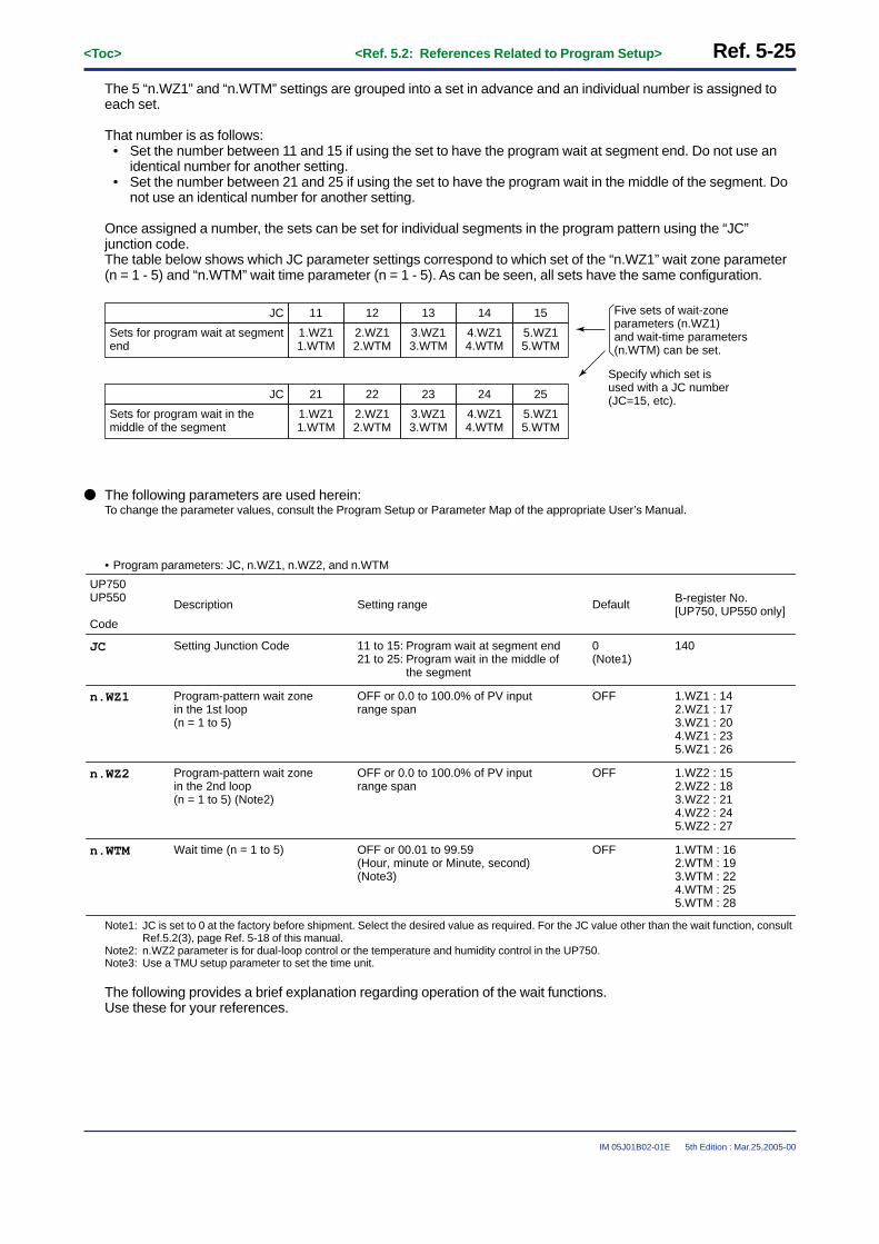
<Toc> <Ref. 5.2: References Related to Program Setup> Ref. 5-25
IM 05J01B02-01E 5th Edition : Mar.25,2005-00
The 5 “n.WZ1” and “n.WTM” settings are grouped into a set in advance and an individual number is assigned toeach set.
That number is as follows:• Set the number between 11 and 15 if using the set to have the program wait at segment end. Do not use an
identical number for another setting.• Set the number between 21 and 25 if using the set to have the program wait in the middle of the segment. Do
not use an identical number for another setting.
Once assigned a number, the sets can be set for individual segments in the program pattern using the “JC”junction code.The table below shows which JC parameter settings correspond to which set of the “n.WZ1” wait zone parameter(n = 1 - 5) and “n.WTM” wait time parameter (n = 1 - 5). As can be seen, all sets have the same configuration.
11
1.WZ11.WTM
JC
Sets for program wait at segment end
12
2.WZ12.WTM
13
3.WZ13.WTM
14
4.WZ14.WTM
15
5.WZ15.WTM
21
1.WZ11.WTM
JC
Sets for program wait in the middle of the segment
22
2.WZ12.WTM
23
3.WZ13.WTM
24
4.WZ14.WTM
25
5.WZ15.WTM
Five sets of wait-zone parameters (n.WZ1) and wait-time parameters (n.WTM) can be set.
Specify which set is used with a JC number (JC=15, etc).
● The following parameters are used herein:To change the parameter values, consult the Program Setup or Parameter Map of the appropriate User’s Manual.
• Program parameters: JC, n.WZ1, n.WZ2, and n.WTM
UP750UP550
Code
Setting range
11 to 15: Program wait at segment end21 to 25: Program wait in the middle of
the segment
0 (Note1)
Default
140
B-register No.[UP750, UP550 only]
JC
Description
Setting Junction Code
OFF or 0.0 to 100.0% of PV input range span
OFF 1.WZ1 : 142.WZ1 : 173.WZ1 : 204.WZ1 : 235.WZ1 : 26
n.WZ1 Program-pattern wait zone in the 1st loop (n = 1 to 5)
OFF or 0.0 to 100.0% of PV input range span
OFF 1.WZ2 : 152.WZ2 : 183.WZ2 : 214.WZ2 : 245.WZ2 : 27
n.WZ2 Program-pattern wait zone in the 2nd loop (n = 1 to 5) (Note2)
OFF or 00.01 to 99.59 (Hour, minute or Minute, second)(Note3)
OFF 1.WTM : 162.WTM : 193.WTM : 224.WTM : 255.WTM : 28
n.WTM Wait time (n = 1 to 5)
Note1: JC is set to 0 at the factory before shipment. Select the desired value as required. For the JC value other than the wait function, consultRef.5.2(3), page Ref. 5-18 of this manual.
Note2: n.WZ2 parameter is for dual-loop control or the temperature and humidity control in the UP750.Note3: Use a TMU setup parameter to set the time unit.
The following provides a brief explanation regarding operation of the wait functions.Use these for your references.

Ref. 5-26<Toc> <Ref. 5.2: References Related to Program Setup>
IM 05J01B02-01E 5th Edition : Mar.25,2005-00
■ Program wait at segment end (Set “JC” to 11 - 15.)
Program wait at segment end makes the program wait at segment end if PV has not attained the target setpoint.The program will advance to the next segment the moment that the measured input attains the wait zone.If the measured input does not attain the wait zone within the wait time, the program will advance to the nextsegment the moment the wait time elapses.
● Operation when the measured input attains the wait zone before the wait time elapsesFrom when the wait operation starts, if the measured input attains the wait zone, the wait state is changed to theoperating state and the program advances to the next segment.During the wait state, the program timer is stopped, therefore the time event (EVn) value is held.
SEG.n SEG.n+1n=1 to 98
EVn EVn+1
Wait zone
Wait zone
Program timerstopped here.
Wait time
PV
The moment that the PV attainsthe wait zone, the program advancesto the next segment (SEG.n + 1).
Ramp to target setpoint
Target setpoint
Fig. 5-2-14 Example of wait operation when the measured input attains the wait zone before the wait timeelapses
● Operation when the measured input does not attain the wait zone within the wait timeIf the wait time elapses before the measured input attains the wait zone, the wait state is changed to the operatingstate and the program advances to the next segment the moment that the wait time elapses. This happens even ifthe measured input has not attained the wait zone.
SEG.n SEG.n+1n=1 to 98
EVn EVn+1
Wait zone
Wait zone
Program timerstopped here.
Wait time
PV
Though PV has not attained the wait zone,the program advances to the next segment (SEG.n + 1)the moment that the wait time elapses.
Ramp to target setpoint
Target setpoint
Fig. 5-2-15 Example of wait operation when the measured input does not attain the wait zone within the waittime
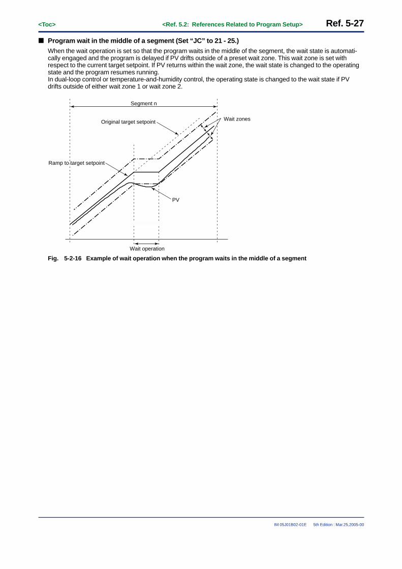
<Toc> <Ref. 5.2: References Related to Program Setup> Ref. 5-27
IM 05J01B02-01E 5th Edition : Mar.25,2005-00
■ Program wait in the middle of a segment (Set “JC” to 21 - 25.)
When the wait operation is set so that the program waits in the middle of the segment, the wait state is automati-cally engaged and the program is delayed if PV drifts outside of a preset wait zone. This wait zone is set withrespect to the current target setpoint. If PV returns within the wait zone, the wait state is changed to the operatingstate and the program resumes running.In dual-loop control or temperature-and-humidity control, the operating state is changed to the wait state if PVdrifts outside of either wait zone 1 or wait zone 2.
Segment n
Wait operation
PV
Wait zonesOriginal target setpoint
Ramp to target setpoint
Fig. 5-2-16 Example of wait operation when the program waits in the middle of a segment

Ref. 5-28<Toc> <Ref. 5.2: References Related to Program Setup>
IM 05J01B02-01E 5th Edition : Mar.25,2005-00
[2] For the UP35�
With the UP35�, the wait function is used at the end of the segment.It works only when a ramp (up or down) segment changes to a soak segment.
The wait function is set during program setup using the “WIT.Z” wait zone parameter and the “WIT.T” wait timeparameter.Settings apply to both program patterns 1 and 2.Note: That the weight function does not work if the weight time “WIT.T” remains off.
● The parameters used herein are as follows:To change the parameter values, follow the Program Setup or Parameter Map section in the appropriate User’s Manual.
• Program parameters: WIT.Z and WIT.T
UP35�
Code
Description Setting range
OFF or 0.0 to 100.0% of PV input range span
OFF or 0.01 to 99.59
OFF
OFF
Default
Wait Zone
(WIT.Z)
(WIT.T)Wait Time
D-register No.
260
261
The following provides a brief explanation regarding operation of the wait functions.Use these for your references.
● Operation when the measured input attains the wait zone before the wait time elapsesFrom when the wait operation starts, if the measured input attains the wait zone, the wait state is changed to theoperating state and the program advances to the next segment.During the wait state, the program timer is stopped, therefore the time event (EVn) value is held.
SEG.n SEG.n+1n=1 to 98
EVn EVn+1
Wait zone
Wait zone
Program timerstopped here.
Wait time
PV
The moment that the PV attainsthe wait zone, the program advancesto the next segment (SEG.n + 1).
Ramp to target setpoint
Target setpoint
Fig. 5-2-17 Example of wait operation when the measured input attains the wait zone before the wait timeelapses

<Toc> <Ref. 5.2: References Related to Program Setup> Ref. 5-29
IM 05J01B02-01E 5th Edition : Mar.25,2005-00
● Operation when the measured input does not attain the wait zone within the wait timeIf the wait time elapses before the measured input attains the wait zone, the wait state is changed to the operatingstate and the program advances to the next segment the moment that the wait time elapses. This happens even ifthe measured input has not attained the wait zone.
SEG.n SEG.n+1n=1 to 98
EVn EVn+1
Wait zone
Wait zone
Program timerstopped here.
Wait time
PV
Though PV has not attained the wait zone,the program advances to the next segment (SEG.n + 1)the moment that the wait time elapses.
Ramp to target setpoint
Target setpoint
Fig. 5-2-18 Example of wait operation when the measured input does not attain the wait zone within the waittime

Ref. 5-30<Toc> <Ref. 5.2: References Related to Program Setup>
IM 05J01B02-01E 5th Edition : Mar.25,2005-00
<<Ref. 5.2: References Related to Program Setup>>Ref.5.2(5) Using the Hold Functions (Changing Segment Setpoint in Hold Status)
Functions that change the segment setpoint in the hold status apply to Models UP750, UP550, and UP35�.
This “hold” function enables program control to be in the hold status (the timer stops) while the program is running(see Note1 below).In this hold status, the following three segment setpoints can be changed (see also Note2).
• Changing the target segment setpoint• Increasing the segment ramp time• Decreasing the segment ramp time
This section describes the operations after individual setpoints are changed.
Note1: Junction codes, key operations, and external contacts enable programs to be in the hold status. For key operations, see the ProgramSetup section of the appropriate User’s Manual available separately. For external contacts by which programs are in the hold status,see Ref. 3.1, “References Related to Contact Input.”
Note2: To change each setpoint, see the Program Setup section in the appropriate User’s Manual.
CAUTIONChanges can be made to parameter settings only during soak segments (constant setpoint) that are on hold.However, with dual-loop control on the UP750, see the TIP below.
CAUTION• The UP750, UP550, and UP35� can change the target segment setpoint to more advanced settings than
the currently operating segment, and changes are applied to operation.• With the UP750, UP550 and UP35�, it is possible to change the target setpoint parameter of a running
program from the program parameter display during a ramp segment. Changes will not be applied tooperation. The program will continue towards the previously set target setpoint.
• With the UP750 and UP550, if the program is first put on hold and then the target setpoint parameter of thatprogram is changed from the program parameter display, the program will resume towards the new targetsetpoint the moment that the hold state is released. It is also possible, during the hold state, to change thetarget setpoint of segments yet to be run and have those changes applied to operation.However, set the segment setting to “time-set segment time”, and the “HOLDSP” and “HOLDTIME” param-eters must not be changed while the program is on hold.

<Toc> <Ref. 5.2: References Related to Program Setup> Ref. 5-31
IM 05J01B02-01E 5th Edition : Mar.25,2005-00
■ To change the target segment setpoint
CAUTIONChanges can be made to parameter settings for soak segments only (constant setpoint) that are on hold.However, when the UP750 is in the dual-loop control mode or in the temperature and humidity control mode,or when the setup parameter “PT2.G” in other the UP mode is on, follow the TIP below.
Fig. 5-2-19 shows where the target segment setpoint can be changed while in the hold status.If the program control is in the hold status, the time event and segment time are extended following the time overwhich the program remains held.
Hold interval(timer stops)
Time delayed by timer stops
TSP: Target setpoint
Time eventOn
Off
SEG1 SEG2 SEG3 SEG4 SEG5
TSP
Program pattern after changing
the setpointChanged the target setpoint
Program pattern before changing the setpoint
Fig. 5-2-19 Changing target setpoint in hold status
TIPWhen running 2 patterns simultaneously with the UP750, as long as both the held segments in the primaryloop pattern and the secondary loop pattern are soak segments, both target setpoints can be changed.If only one is a soak segment, then only the target setpoint for that segment can be changed. That of theanother pattern cannot.

Ref. 5-32<Toc> <Ref. 5.2: References Related to Program Setup>
IM 05J01B02-01E 5th Edition : Mar.25,2005-00
■ To increase the segment (ramp) time
CAUTIONChanges can be made to parameter settings for soak segments only (constant setpoint) that are on hold.However, when the UP750 is in the dual-loop control mode or in the temperature and humidity control mode,or when the setup parameter “PT2.G” in other the UP mode is on, follow the TIP below.
Fig. 5-2-20 shows where the segment time can be increased while in the hold status.If the segment time is increased, the time event and segment time are delayed (automatically adjusted) followingthe time over which the program segment is held, and an increment of the segment (ramp) time.
SEG1 SEG2 SEG5SEG4SEG3
TSP
Delayedsegment time
Hold interval(timer stops)
Time delayed by timer stops
TSP: Target setpoint
Time eventOn
Off
Segment patternbefore the segment
time is increased
Segment pattern after the segment time
has been increased
Fig. 5-2-20 Segment time delayed by timer stops
TIPWhen running 2 patterns simultaneously with the UP750, as long as both the held segments in the primaryloop pattern and the secondary loop pattern are soak segments, the segment time can be changed.

<Toc> <Ref. 5.2: References Related to Program Setup> Ref. 5-33
IM 05J01B02-01E 5th Edition : Mar.25,2005-00
■ To decrease the segment (ramp) time
CAUTIONChanges can be made to parameter settings for soak segments only (constant setpoint) that are on hold.However, when the UP750 is in the dual-loop control mode or in the temperature and humidity control mode,or when the setup parameter “PT2.G” in other the UP mode is on, follow the TIP below.
Fig. 5-2-21 shows where the segment time can be decreased while in the hold status.If the segment time is decreased, the time event and segment time are automatically adjusted following the timeover which the program segment is held, and a decrement of the segment (ramp) time.
SEG1 SEG2 SEG5SEG4SEG3
Decreasedsegment time
Time delayed by timer stops
Time-event decreased by a decrement of segment time
Hold interval(timer stops)
On
OffTime event
TSP
Segment patternbefore the segmenttime is decreased
Segment patternafter the segment timehas been decreased
Fig. 5-2-21 Segment time decreased in hold state
TIPWhen running 2 patterns simultaneously with the UP750, as long as both the held segments in the primaryloop pattern and the secondary loop pattern are soak segments, the segment time can be changed.

Ref. 5-34<Toc> <Ref. 5.2: References Related to Program Setup>
IM 05J01B02-01E 5th Edition : Mar.25,2005-00
<<Ref. 5.2: References Related to Program Setup>>Ref.5.2(6) Using the Repeat Functions
Repeat functions enable you to repeat successive segments in a program pattern a multiple number of times.There are some differences in using these functions between the UP750, UP550 and UP35�.This section first provides those functions for the UP750 and UP550.For those that apply to the UP35�, see Page Ref. 5-36 later in this manual.Refer to either of these as appropriate for your selected model.
[1] For the UP750 and UP550
CAUTION• The moment that the repeat operation starts, the event settings for the segments in that operation are
defaulted.For this reason, reset any events needed in the repeat operation.
• If the “STC” program start condition parameter is set to either PV ramp start or PV time start, the startcondition is applied to the repeat operation when it starts.
To use the repeat operation, set the repeat start segment, repeat end segment and number of repeat cycles.
The next page shows the difference in program pattern progression when repeat operation is used and when not.
RCY (repeat cycles) = 1RST (repeat start segment No.) = 3REN (repeat end segment No.) = 5
With the above settings, segments Nos. 3 to 5 are repeated 1 time as shown on the next page.
● The following parameters are used:To change parameter values, follow the Program Setup or Parameters section of the appropriate User’s Manual.
• Program parameters (repeat operation parameters): RCY, RST, and REN
UP750UP550
Code
Setting range
0 to 999, CONT (Indefinite repetitions)
0: (no repeat operation)
1
Default
REN1 � RST � REN � 99
RST Start of repetition segment number
RCY Number of repetitions
End of repetition segment number
1
Description B-register No.[UP750, UP550 only]
29
30
31

<Toc> <Ref. 5.2: References Related to Program Setup> Ref. 5-35
IM 05J01B02-01E 5th Edition : Mar.25,2005-00
■ Program pattern without the repeat operation
Fig. 5-2-22 shows the program pattern without the repeat operation.
SEG4SEG3SEG2
TSP2
TSP1
SEG1 SEG5 SEG6
TSPn: Target setpoint
Secondary loopprogram pattern
Primary loopprogram pattern
Fig. 5-2-22 Program pattern without the repeat operation
TIP
The above figure is for dual-loop control with the UP750. The secondary loop program pattern is also shown. Ifit were single loop control, there would be no secondary loop program pattern.
■ Program pattern with the repeat operation
Fig. 5-2-23 shows the program pattern with one repeat cycle.Repeat cycle = 1, Repeat start segment = 3, Repeat end segment = 5
TSP1
TSP2
SEG4 SEG6SEG5SEG3SEG5SEG4SEG3SEG2SEG1
Repeated cycle x 1
Repeat startsegment = 3
Repeat endsegment = 5TSPn: Target setpoint
Secondary loopprogram pattern
Primary loopprogram pattern
Fig. 5-2-23 Program pattern with one repeat cycle

Ref. 5-36<Toc> <Ref. 5.2: References Related to Program Setup>
IM 05J01B02-01E 5th Edition : Mar.25,2005-00
[2] For the UP35�
With the UP35�, the repeat function can be used by setting the junction code either “1.JC” or “2.JC.”
Though the UP35� can run two program patterns, the repeat function set with “1.JC” or “2.JC” is applied to bothpatterns.
The repeat function must start from segment number 1.All event settings can also be used during the repeat operation as they are.Once the repeat operation starts, it will continue operation until otherwise stopped by key operations, externalcontacts, or via communications.
The following shows where an identical program pattern will be repeated.
SEG2 SEG5SEG4SEG3SEG1SEG5SEG4SEG3SEG2SEG1
Start repetition
Time
1st program pattern 1st program pattern
Repeated until stop operation is executed.
Starts from segment number 1
Fig. 5-2-24 Program pattern with program 1 repetition specified
● The following parameters are used:To change parameter values, follow the Program Setup or Parameters section in the appropriate User’s Manual.
• Program parameters (junction-code parameters): 1.JC, 2.JC
Description Setting range
2: Pattern 1 startup3: Pattern 2 startup
Set 2 or 3 above to setrepeat operation.
0: End of resetting(Repeat operation is not set at the factory before shipment.)
Default
UP35�
Code
Junction code (for program pattern 2)
Junction code (for program pattern 1)(1.JC)
(2.JC)

<Toc> <Ref. 5.2: References Related to Program Setup> Ref. 5-37
IM 05J01B02-01E 5th Edition : Mar.25,2005-00
<<Ref. 5.2: References Related to Program Setup>>Ref.5.2(7) Using the Advance Functions
The advance function enables a program to be advanced forcibly to the next segment while the program isrunning.
This section describes how to operate the advance function.Operation of the advance function for the UP750 and UP550 is different from that for the UP35�.The following shows operation of the advance function for the UP750 and UP550.For that for the UP35�, consult page Ref. 5-38.Use the advance function as appropriate for your needs.
[1] For the UP750 and UP550
NoteThe advance function is set by key input, external contact input or communication command.For external contact input, see Ref. 3-1: References Related to Contact Input earlier in this manual. For thecommunication function, see the separate GREEN Series Communications User’s Manual.
The advance function can be used by key input as follows: Press the MODE key on the operating display to highlight“ADV: ON”. Next, press the SET/ENT key. For more information on key input, see the User’s Manual Operations.
Applying the advance function to the currently running segment advances the program to the next segment.However, operation differs, as follows, depending on the operating state of the segment.
■ If the advance function is applied during any segment other than the last segment of the program pattern, theprogram advances to the next segment, regardless of the “JC” setting.
■ If the advance function is applied in the last segment of the program pattern, the programs acts according tothe “JC” setting.For example, if “JC” = 2 (local control) is set, the local (constant setpoint) mode is engaged. See Ref. 5-2: (9)Operation in the Local (Constant Setpoint) Mode on page Ref. 5-41 of this manual.On the other hand, if “JC” = 0 (program continue) or “JC” = 1 (segment hold), the program is reset (stopped).Control output in this case is the preset output.
■ If the advance function is applied in the repeat end segment, the repeat operation is started.
■ If the advance function is applied while the program is on hold, the hold state is released and the programresumes from the next segment.

Ref. 5-38<Toc> <Ref. 5.2: References Related to Program Setup>
IM 05J01B02-01E 5th Edition : Mar.25,2005-00
[2] For the UP35�
NoteThe advance function is performed through key operation or via communications. For the applications ofcommunication functions, see the separate GREEN Series Communications User’s Manual.
To use the advance function by key input, highlight the “ADV” operating parameter for the running pattern and setit to “1”.After the advance function has been applied, the monitor will automatically return to the operating display (PV/SPdisplay).For more information on key input, see the User’s Manual Operations.
Applying the advance function to the currently running segment advances the program to the next segment.However, operation differs, as follows, depending on the operating state of the segment.
■ If the advance function is applied during any segment other than the last segment of the program pattern, theprogram advances to the next segment, regardless of the “1.JC” or “2.JC” (Note) setting.
■ If the advance function is applied in the last segment of the program pattern, the programs acts as followsdepending on the “1.JC” or “2.JC” (Note) setting.
0: Reset (Operation stopped)1: Segment hold2: Program pattern 1 start3: Program pattern 2 start
Reset (Operation stopped) stateReset (Operation stopped) stateProgram pattern 1 runningProgram pattern 2 running
“1.JC” or “2.JC” setting for last segment operating state after advance function is appliedand
■ If the advance function is applied while the program is on hold, the hold state is released and the programresumes from the next segment.
Note: With the UP350, two program patterns can be run simultaneously. “1.JC” is the junction code for program pattern 1 and “2.JC” forprogram pattern 2.

<Toc> <Ref. 5.2: References Related to Program Setup> Ref. 5-39
IM 05J01B02-01E 5th Edition : Mar.25,2005-00
<<Ref. 5.2: References Related to Program Setup>>Ref.5.2(8) Signal Output at Program end
This function can be used with UP750 or UP550.
The pattern-end signal output function outputs a signal via a relay contact at program end. However, the pattern-end signal is not output when the program operation is forcibly ended by key operation, communication or contactinput. If the several program patterns are linked (pattern link), the pattern-end signal is output when the linkedprogram pattern is ended. The contact remains ON for 1, 3 or 5 seconds to output the signal.The pattern end signal can be used by assigning the controller’s internal “I relay” (No. 5157, 5158 or 5159) to theexternal output terminals (DO1 - DO7) (refer to Table 5-2-1).It is also possible with the UP750 and the optional I/O expansion module (Note1) to use the pattern-end signal byassigning the controller’s internal “I relay” (No. 5157, 5158 or 5159) to the module output terminals (OUTPUT51 -OUTPUT58).Note1: For information on the contact I/O expansion module, see Section Ref.3.2, earlier in this manual.
CAUTIONThe following example only shows how to assign the pattern-end signal in UP mode 1. For instruction on howto assign the “I relay” in other modes, see Section Ref.3.2, earlier in this manual.
With the UP750 and UP550, parameters (DO1 - DO7) that set output functions in UP mode 1 are assigned to theterminals as shown in the table below.To assign the pattern end signal to one of these output terminals, it is necessary to change these parameters fromtheir factory-set defaults.Accordingly, check the terminal assignments in the table below and assign pattern-end signal output to theindicated terminal.
Terminal number
6
5
4
34
33
32
31
Parameter
DO1
DO2
DO3
DO4
DO5
DO6
DO7
Output
Relay
Relay
Relay
Transistor
Transistor
Transistor
Transistor
Function
Outputs PV event 1.
Outputs PV event 2.
Outputs alarm output 1 (or cooling output in heating and cooling control) (Note1).
Outputs time-event 1 (or cooling output in heating and cooling control) (Note1).
Transistor Outputs time-event 2.
Transistor Outputs time-event 3.
Transistor Outputs time-event 4.
For example, to assign pattern-end signal output to parameter “DO7” (sets terminal No. 31), complete the follow-ing steps.
1: Get the “DO7” parameter setting display from the [DO] submenu on the [CONF] main menu. See theUser’s Manuals Initial Settings and Parameters.
2: From the “I Relay” Table (Table 5-2-1), check the “I relay” number assigned to the pattern-end signal(PTEND) is “157”.
3: Change the “DO7” parameter setting to “5157” and press the SET/ENT key. (Add 5000 to 157, “I relay ” No. and
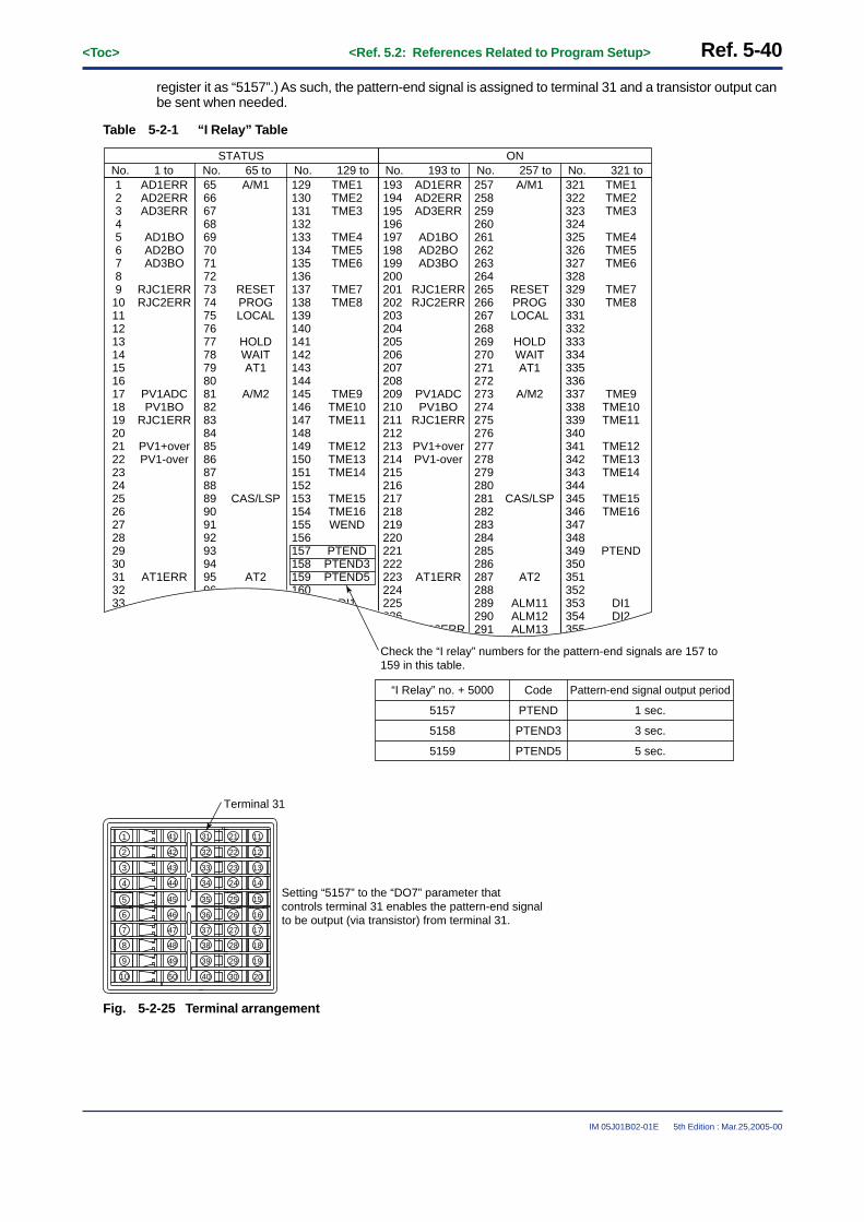
Ref. 5-40<Toc> <Ref. 5.2: References Related to Program Setup>
IM 05J01B02-01E 5th Edition : Mar.25,2005-00
register it as “5157”.) As such, the pattern-end signal is assigned to terminal 31 and a transistor output canbe sent when needed.
Table 5-2-1 “I Relay” Table
No.123456789101112131415161718192021222324252627282930313233
AD1ERRAD2ERRAD3ERR
AD1BOAD2BOAD3BO
RJC1ERRRJC2ERR
PV1ADCPV1BO
RJC1ERR
PV1+overPV1-over
AT1ERR
6566676869707172737475767778798081828384858687888990919293949596
A/M1
RESETPROGLOCAL
HOLDWAITAT1
A/M2
CAS/LSP
AT2
129130131132133134135136137138139140141142143144145146147148149150151152153154155156157158159160
TME1TME2TME3
TME4TME5TME6
TME7TME8
TME9TME10TME11
TME12TME13TME14
TME15TME16WEND
PTENDPTEND3PTEND5
DI1
1 to No. 65 to No. 129 toSTATUS
No.193194195196197198199200201202203204205206207208209210211212213214215216217218219220221222223224225226
AD1ERRAD2ERRAD3ERR
AD1BOAD2BOAD3BO
RJC1ERRRJC2ERR
PV1ADCPV1BO
RJC1ERR
PV1+overPV1-over
AT1ERR
RJC2ERR
257258259260261262263264265266267268269270271272273274275276277278279280281282283284285286287288289290291
A/M1
RESETPROGLOCAL
HOLDWAITAT1
A/M2
CAS/LSP
AT2
ALM11ALM12ALM13
321322323324325326327328329330331332333334335336337338339340341342343344345346347348349350351352353354355
TME1TME2TME3
TME4TME5TME6
TME7TME8
TME9TME10TME11
TME12TME13TME14
TME15TME16
PTEND
DI1DI2
193 to No. 257 to No. 321 toON
Check the “I relay” numbers for the pattern-end signals are 157 to 159 in this table.
“I Relay” no. + 5000 Code Pattern-end signal output period
5157 PTEND 1 sec.
5158 PTEND3 3 sec.
5159 PTEND5 5 sec.
1
2
3
4
8
6
5
7
9
10
12
13
14
16
17
18
19
28
29
30 20
26
27
15
21
22
23
24
25
11
40
35
50
45
42
43
44
41
46
47
48
49
32
33
34
31
36
37
38
39
Terminal 31
Setting “5157” to the “DO7” parameter thatcontrols terminal 31 enables the pattern-end signalto be output (via transistor) from terminal 31.
Fig. 5-2-25 Terminal arrangement

<Toc> <Ref. 5.2: References Related to Program Setup> Ref. 5-41
IM 05J01B02-01E 5th Edition : Mar.25,2005-00
<<Ref. 5.2: References Related to Program Setup>>Ref.5.2(9) Operation in Local Mode (with Constant Target Setpoint)
The UP750 and UP550 can be operated in the local mode.
In addition to this mode, the following four modes are available in the UP750 and UP550.Each mode can be transferred with the MODE key.
Hold operation modeProgram operation mode
Program operation
MODE key(HOLD = 1)
MODE key(LOC = 1)
RUN key
RUNkey
RESETkey
MODEkey
(LOC = 1)
RUNkey
RESET key
Local modeReset mode
Fig. 5-2-26 Switching Between Operation Modes
The controller can be transferred to local mode with the MODE key while the program is running.
CAUTIONThe operation mode can be transferred with a key operation, by external contacts or via communications.When transferring through external contacts, see Section Ref. 3.1 earlier in this manual. When transferring viacommunications, see the separate GREEN Series Communications User’s Manual.
In the local mode, the controller runs at the target (constant) setpoint set with the program parameter “LSP1”(Note1).For this, set “LSP1” and the other parameters shown in the following table to the required values before runningthe controller in the local mode.Note1: LSP2 can also be used when using dual-loop control or temperature and humidity control with the UP750.
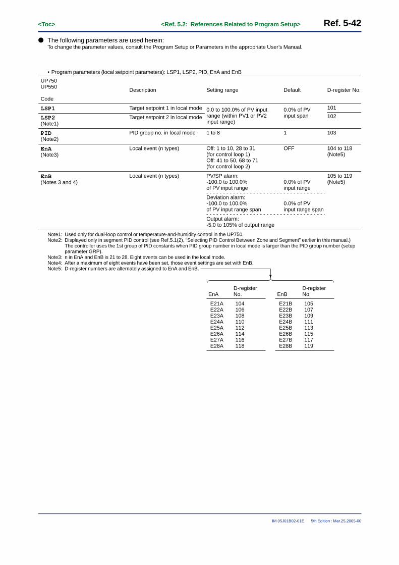
Ref. 5-42<Toc> <Ref. 5.2: References Related to Program Setup>
IM 05J01B02-01E 5th Edition : Mar.25,2005-00
● The following parameters are used herein:To change the parameter values, consult the Program Setup or Parameters in the appropriate User’s Manual.
• Program parameters (local setpoint parameters): LSP1, LSP2, PID, EnA and EnB
UP750UP550
Code
Description Setting range
0.0 to 100.0% of PV input range (within PV1 or PV2 input range)
101
102
103
0.0% of PV input span
1
Default D-register No.
LSP2(Note1)
LSP1 Target setpoint 1 in local mode
Target setpoint 2 in local mode
PID group no. in local mode
Local event (n types)
Local event (n types)
1 to 8
Off: 1 to 10, 28 to 31(for control loop 1)Off: 41 to 50, 68 to 71 (for control loop 2)
PV/SP alarm: -100.0 to 100.0% of PV input range
PID(Note2)
EnA(Note3)
EnB(Notes 3 and 4)
OFF
0.0% of PV input range
0.0% of PV input range span
104 to 118(Note5)
105 to 119(Note5)
Deviation alarm: -100.0 to 100.0% of PV input range span
Output alarm: -5.0 to 105% of output range
Note1: Used only for dual-loop control or temperature-and-humidity control in the UP750.Note2: Displayed only in segment PID control (see Ref.5.1(2), “Selecting PID Control Between Zone and Segment” earlier in this manual.)
The controller uses the 1st group of PID constants when PID group number in local mode is larger than the PID group number (setupparameter GRP).
Note3: n in EnA and EnB is 21 to 28. Eight events can be used in the local mode.Note4: After a maximum of eight events have been set, those event settings are set with EnB.Note5: D-register numbers are alternately assigned to EnA and EnB.
EnA
E21AE22AE23AE24AE25AE26AE27AE28A
D-register No.
104106108110112114116118
EnB
E21BE22BE23BE24BE25BE26BE27BE28B
D-register No.
105107109111113115117119

<Toc> <Ref. 5.2: References Related to Program Setup> Ref. 5-43
IM 05J01B02-01E 5th Edition : Mar.25,2005-00
Part of the parameter map (for the UP750) is given below.Refer to this to display the desired parameter display.
UP 750 Program Parameter Map
From the operating parametermap main menu [PROG]
SET
menuSub
NO
LOC
PTN
TSP1
TM.RTTIMETSP2
YES
PRG EDIT
“PTN” = 1 to 300 (UP750), 1 to 30 (UP550)“SEG” = 1 to 99 (UP750, UP550)SEG
DISP
DISP
ENTENT DISP
SET
PTN300PTN1
[UP750]
[UP550]
PTN30
Same asPTN1
0 1 2 99
PID
S.NO
COPYE.NOP.NO
CLR
EVnONnOFFnTYnPEn
JC
TSP1
TM.RTTIMETSP2
PID
EVnONnOFFnTYnPEn
JC
TSP1
TM.RTTIMETSP2
PID
EVnONnOFFnTYnPEn
JC
RCYRSTREN
1.WZ1
1.WTM1.WZ2
SSP1
STCSSP2
2.WZ12.WZ22.WTM3.WZ1
3.WTM3.WZ2
4.WZ14.WZ24.WTM5.WZ15.WZ25.WTM
STC= -1
SET DISP
DISP
SETSET
DISP
LSP1
PIDLSP2
E21AE21BE22AE22B
E23BE23A
E24AE24BE25AE25BE26AE26BE27AE27BE28AE28B
“LSP1”
(Note)
(see Note below)
Note: Display the program parameter submenu [LOC] through the operating parameter main menu [PROG]. Then, display the LSP1 set with
the SET/ENT
key. Press, in turn, the SET/ENT
key to display parameter set displays LSP2 through E28B as indicated above.
On each display, press the / keys to display the desired value, and then press the SET/ENT
key to register that value.

Ref. 5-44<Toc> <Ref. 5.2: References Related to Program Setup>
IM 05J01B02-01E 5th Edition : Mar.25,2005-00
<<Ref. 5.2: References Related to Program Setup>>Ref.5.2(10) Starting the Program Operation at Any Segment
This function is for UP750 and UP550.
For example, this function can be used for restarting the program operation after returning the program in opera-tion to the preceding segment.The following shows an example of starting operation at SEG 3. Note that the controller should be set to RESETmode when it is in operation.
SEG4SEG3SEG2SEG1 SEG5
TimeStarting program operation at SEG3
B
C
A
Tem
pera
ture
When STC=0
Segment time for SEG3
When STC=1
When STC=2
Current PV
The program operation starts according to the Start Code (STC) as follows when starting the program operation atSEG3.
1: When STC=0 (SSP start)Program operation starts at the point A as starting target setpoint to the point C .
2: When STC=1 (Ramp-prioritized PV1 start)Program operation starts at the point B to the point C .
3: When STC=2 (Time-prioritized PV start)Program operation starts at the current PV to the point C with the segment time for SEG3.
4: When STC=3 (Ramp-prioritized PV2 start) – Only for UP750 Dual-loop Control or Temperature andHumidity ControlFor STC=3, refer to Ref.5.2(1), “Selecting Program Start Condition.”

<Toc> <Ref. 5.2: References Related to Program Setup> Ref. 5-45
IM 05J01B02-01E 5th Edition : Mar.25,2005-00
● The following parameter is used (displayed by pressing MODE key on the front panel several times):To change parameter value, follow the Program Setup or Parameters section of the appropriate User’s Manual.
• Operating parameter (Operation Mode parameter): SST
UP750UP550
Code
Setting range
1 to 99 1
Default
SST Program start segment number
Description D-register No.
D0224
Note• Program operation is not started when the segment set in Program Start Segment Number (SST) does not
exist.• SST is back to “1” in program operation RESET mode or LOCAL mode.• EVENT (PV, Time) do not work in the segment precedent to the segment set in the Program Start Segment
Number (SST).• Repeat function and pattern-link function do not work in this function.

Ref. 5-46<Toc> <Ref. 5.2: References Related to Program Setup>
IM 05J01B02-01E 5th Edition : Mar.25,2005-00
<<Ref. 5.2: References Related to Program Setup>>Ref.5.2(11) Operation with Linked Program Patterns (Pattern-link)
This function is for UP750 and UP550.
The following shows an example of linking the program patterns 1 and 2 (pattern-link).
SEG4SEG3SEG2SEG1 SEG5
Time
Time
Time
* Linking the point to the point like the above example disables the operation for SEG5 of the program pattern 1.
B
BA
BALink the point of the program pattern 1 to the point of the program pattern 2 (pattern-link).
Tem
pera
ture
Tem
pera
ture
Tem
pera
ture
A
SEG4SEG3SEG2SEG1 SEG5
Program Pattern 1 Program Pattern 2
and
Link
A B
NoteWhen the temperature difference between the points A and B is large, the derivative item (D-item) worksand the output may travel up to 100% and stay at this point.However, only when Start Code (STC) is set to 0.
For the above pattern-link, set the value added 100 to the program pattern number “2” to be linked, to the JunctionCode (JC) parameter of SEG4 of the program pattern 1. (JC=102)

<Toc> <Ref. 5.2: References Related to Program Setup> Ref. 5-47
IM 05J01B02-01E 5th Edition : Mar.25,2005-00
● The following parameter is used:To change parameter value, follow the Program Setup or Parameters section of the appropriate User’s Manual.
• Program Parameter (Junction Code parameter): JC
UP750UP550
Code
Setting range
101 to 130 (for UP550):Program patterns 1 to 30
101 to 199 (for UP750):Program patterns 1 to 99
0
Default
JC Setting Junction code
Description D-register No.
140

Ref. 5-48<Toc> <Ref. 5.3: Handy Features for Creating and Editing Programs>
IM 05J01B02-01E 5th Edition : Mar.25,2005-00
Ref.5.3: Handy Features for Creating and Editing Programs
IMPORTANT: Applicable models of this sectionUP750 UP550 UP35� UT750 UT5�� UT4�0 UT3�� UM3�0
UP750-�� UP550-�� None(Note)
None None None None None
Note: These functions are not available with the UP35�.
This section contains reference information on the following aspects of program creating and editing.This information can be particularly handy in creating new program patterns from existing patterns.Refer to and use this information only if necessary.
(1) Checking the Total Number of Unused Segments(2) Checking the number of segments in a specific Program Pattern(3) Checking the number of all unused events(4) Copying Program Patterns(5) Deleting Program Patterns(6) Adding (Inserting)/Deleting segments in Program Patterns
<<Ref. 5.3: Handy Features for Creating and Editing Programs>>Ref.5.3(1) Checking the Total Number of Unused Segments
The total number of unused segments amongst all program patterns can be checked with the UP750 and UP550.
The total number of segments allowed with the UP750 is 3,000.That for the UP550 is 300.The more program patterns (Note1) are created, the less unused segments are left.This function can be used to check how many segments are left before creating a new program pattern.Note1: A single program pattern can contain a maximum of 99 segments.
● The parameter used to check the total number of unused segments is as follows.
• Program Parameter (Parameters for Editing Programs): ALL.S
UP750UP550
Code
Setting range
None (Note1)
ALL.S
Description
Shows the number of remainingunused segments
DefaultB-register No. [UP750, UP550 only]
8 or 108 (Note2)
Note1: The “ALL.S” (S.NO =) parameter is used only to display the total number of unused segments. It need not be set.Note2: The number of total unused parameters (B register No. 8 or 108) can be read by writing 1 for the read flag of B register 3 (RDTRG),
after writing the No. of any used program pattern and a segment No. in B registers 1 (PTNO) and 2 (SEGNO).

<Toc> <Ref. 5.3: Handy Features for Creating and Editing Programs> Ref. 5-49
IM 05J01B02-01E 5th Edition : Mar.25,2005-00
To check the number of remaining unused segments, carry out the operation shown below.
1: Refer to the “Parameter Map” and “Program Parameter Map” in the user’s Manual.First, display the operating parameter main menu [PROG], then press the SET/ENT key to display the programparameter setting display. (Submenu [LOC] will be displayed.)
2: And then press / keys to display the submenu [EDIT].
sub menuprogram editEDIT
UP750, UP550 Parameter Map
Sub menu
Operating Parameter[PROG]
LOC PRG EDIT
S.NO
COPYE.NOP.NO
CLR
SET DISP
DISP
SET
/
“ALL.S”(S.NO)
[EDIT]
3: Press the SET/ENT key one time to display the parameter “ALL.S” (S.NO).The remaining unused segments number is shown on this display.
MENU :PROG/EDITunused segment no.
S.NO = 3000
# 1
The remaining unused segment numbers
TIP: The remaining unused segments number is displayed in LCD display as shown below.This time, the parameter code “ALL.S” is displayed on PV display (LED).

Ref. 5-50<Toc> <Ref. 5.3: Handy Features for Creating and Editing Programs>
IM 05J01B02-01E 5th Edition : Mar.25,2005-00
<<Ref. 5.3: Handy Features for Creating and Editing Programs>>Ref.5.3(2) Checking the number of segments in a specific Program Pattern
The number of segments in a specific program pattern can be checked with the UP750 and UP550.
With both the UP750 and UP550, a single program can contain a maximum of 99 segments.
This function can be used to check how many segments can be added to a program pattern before actually addingthem to the program.
● The parameter used to check the number of segments in a specific program pattern is as follows.
• Program Parameter (Parameters for Editing Programs): Ptn.S
UP750UP550
Code
Setting range
None (Note1)
Ptn.S
Description
Shows the number of segments within a pattern
Default B-register No.[UP750, UP550 only]
10 (Note2)
Note1: The “Ptn.s” (P.NO) parameter is used only to display the number of segments within a program. It need not be set.Note2: The number of segments within a program (B-register No.10) can be read by writing 1 for the read flag of B-register 3 (RDTRG), after
writing the program pattern No. in B-register 1 (PTNO).
To check the number of segments in a specific pattern, carry out the operation shown below.
1: Refer to the “Parameter Map” and “Program Parameter Map” in the user’s Manual.First, display the operating parameter main menu [PROG], then press the SET/ENT key to display the programparameter setting display. (Submenu [LOC] will be displayed.)
2: And then press / keys to display the submenu [EDIT] .
LOC PRG EDIT
S.NO
COPYE.NOP.NO
CLR
SET DISP
DISP
SET
/
UP750, UP550 Parameter Map
Sub menu
Operating Parameter[PROG]
“Ptn.S”(P.NO)
[EDIT]sub menu
program editEDIT

<Toc> <Ref. 5.3: Handy Features for Creating and Editing Programs> Ref. 5-51
IM 05J01B02-01E 5th Edition : Mar.25,2005-00
3: Press the SET/ENT key two times to display the parameter “Ptn.S” (P.NO).Press / keys to specify a pattern No, and press SET/ENT key to register it.
MENU :PROG/EDITuse segment-PTno.
P.NO = 1
# 2TIP: The message “use segment-Ptno.” is displayed
in LCD display as shown in the figure.This time, the parameter code “Ptn.S” is displayed on PV display (LED).
The program pattern number
4: The following “S.No” display will be displayed.The number of segments within the pattern can be checked with this display.
MENU :PROG/EDITuse segment.
S.NO = 10
# 3The number of segments within the pattern
<<Ref. 5.3: Handy Features for Creating and Editing Programs>>Ref.5.3(3) Checking the number of all unused events
The number of all unused events can be checked with UP750 and UP550.
The total number of events allowed with the UP750 is 4,000.That for the UP550 is 400.The more program patterns (Note1) are created, the less unused events are left.This function can be used to check how many events are left before creating a new program pattern.
Note1: The maximum of 16 time events and 8 PV events can be used in the segment under operation. A single segment can contain maximumof 8 events. However, the total number of event signal outputs is 7 for both PV events and time events combined. With the optional I/Oexpansion module, an additional 16 outputs can be added.
● The parameter used to check the number of all unused events is as follows.
• Program Parameter (Parameters for Editing Programs): ALL.E
UP750UP550
Code
Setting range
None (Note1)
ALL.E
Description
Shows the number of remaining unused events
Default B-register No.[UP750, UP550 only]
9 or 109 (Note2)
Note1: The “ALL.E” (E.NO) parameter is used only to display the number of all unused events. It need not be set.Note2: The number of all unused events (B-register No.9 or 109) can be read by writing 1 for the read flag of B-register 3 (RDTRG), after
writing the No. of any used program pattern and a segment No. in B-register 1 (PTNO) and 2 (SEGNO).

Ref. 5-52<Toc> <Ref. 5.3: Handy Features for Creating and Editing Programs>
IM 05J01B02-01E 5th Edition : Mar.25,2005-00
To check the number of all unused events, carry out the operation shown below.
1: Refer to the “Parameter Map” and “Program Parameter Map” in the user’s Manual.First, display the operating parameter main menu [PROG], then press the SET/ENT key to display the programparameter setting display. (Submenu [LOC] will be displayed.)
2: And then press / keys to display the submenu [EDIT].
sub menuprogram editEDIT
UP750, UP550 Parameter Map
Operating Parameter[PROG]
Sub menu
LOC PRG EDIT
S.NO
COPYE.NO
CLR
SET DISP
DISP
SET
P.NO
/
“ALL.E”(E.NO)
[EDIT]
3: Press the SET/ENT key three times to display the parameter “ALL.E” (E.NO).
MENU :PROG/EDITunused event no.
E.NO = 4000
# 4The number of all unused events
TIP: The message “unused event no./ E.NO= ##.” is displayed in LCD display as shown in the figure.This time, the parameter code “ALL.E” is displayed on PV display (LED).

<Toc> <Ref. 5.3: Handy Features for Creating and Editing Programs> Ref. 5-53
IM 05J01B02-01E 5th Edition : Mar.25,2005-00
<<Ref. 5.3: Handy Features for Creating and Editing Programs>>Ref.5.3(4) Copying Program Patterns
CAUTIONIt is impossible to copy the program pattern when the controller is in the program operating mode. Stop (reset)the program operation when you want to copy the program pattern.
The copying program patterns function can be used with UP750 and UP550.
It is possible to copy existing program patterns.This function can simplify the pattern creating process because an existing pattern can be copied and then editedonly in the necessary places.
● The parameter used to copy the program pattern is as follows.
• Program Parameter (Parameters for Editing Programs): Copy
UP750UP550
Code
Copy
Setting range
1 to 30 (when UP550)1 to 300 (when UP750)
Description
Program pattern copying
Default B-register No.[UP750, UP550 only]
none
To copy the program patterns, carry out the operation shown below.
1: Refer to the “Parameter Map” and “Program Parameter Map” in the user’s Manual.First, display the operating parameter main menu [PROG], then press the SET/ENT key to display the programparameter setting display. (Submenu [LOC] will be displayed.)
2: And then press / keys to display the submenu [EDIT].
sub menuprogram editEDIT
LOC PRG EDIT
S.NO
COPYE.NO
CLR
SET DISP
DISP
SET
P.NO
/
UP750, UP550 Parameter Map
Sub menu
Operating Parameter[PROG]
“COPY”
“S.NO”
[EDIT]

Ref. 5-54<Toc> <Ref. 5.3: Handy Features for Creating and Editing Programs>
IM 05J01B02-01E 5th Edition : Mar.25,2005-00
3: Press the SET/ENT key one time to display the parameter “ALL.S” (S.NO).The remaining unused segment numbers is shown on this display.Confirm that the unused segment numbers can be left after copying the new program pattern here.
Note: The program pattern can not be copied when remaining segments are not enough.For example, the program pattern to be copied has 30 segments and the numbers of remaining segment are 20, the program patterncan not be copied.
MENU :PROG/EDITunused segment no.
S.NO = 1500
# 1The remaining unused segment numbers
4: After confirmation of remaining unused segment numbers, press the SET/ENT key three times to display the“copy source-Ptno.” (COPY) setting display.Then, set the source program pattern number which you want to copy to new program pattern numberusing / keys, and press the SET/ENT key to register it.
MENU :PROG/EDITcopy sorce-PTno.
P.NO = 1
# 5TIP: The message “copy source-Ptno.” is displayed
in LCD display as shown below.This time, the parameter code “COPY” is displayed on PV display (LED).
The source program pattern number
5: The message “copy destination-Ptno.” Will be displayed.Set the destination program pattern number using / keys, and press the SET/ENT key to register it.
MENU :PROG/EDITcopy destination-PTno.
P.NO = 2
# 6
The submenu [EDIT] will be displayed automatically after copying the program pattern.
TIP: Copying may need a long time when the source program has many segments or events.When the remaining unused segments or events are few, copying may need a long time too.
The destination program pattern number
sub menuprogram editEDIT

<Toc> <Ref. 5.3: Handy Features for Creating and Editing Programs> Ref. 5-55
IM 05J01B02-01E 5th Edition : Mar.25,2005-00
<<Ref. 5.3: Handy Features for Creating and Editing Programs>>Ref.5.3(5) Deleting Program Patterns
CAUTIONIt is impossible to delete the program pattern when the controller is in the program operating mode. Stop(reset) the program operation when you want to delete the program pattern.
The deleting program patterns function can be used with UP750 and UP550.
Unnecessary program patterns can be deleted.If wanting to create a new pattern but there are not enough segments left to do so, delete any unnecessarypatterns with this function.
● The parameter used to delete the program pattern is as follows.
• Program Parameter (Parameters for Editing Programs): CLEAR
UP750UP550
Code
CLEAR
Setting range
1 to 30 (when UP550)1 to 300 (when UP750) (Note)
Description
Program pattern clearance
Default B-register No.[UP750, UP550 only]
none
Note: The setting values of this parameter are the program pattern numbers those are already registered.
To delete the program patterns, carry out the operation shown below.
1: Refer to the “Parameter Map” and “Program Parameter Map” in the user’s Manual.First, display the operating parameter main menu [PROG], then press the SET/ENT key to display the programparameter setting display. (Submenu [LOC] will be displayed.)
2: And then press / keys to display the submenu [EDIT] .
sub menuprogram editEDIT
LOC PRG EDIT
S.NO
COPYE.NO
CLR
SET DISP
DISP
SET
P.NO
/
UP750, UP550 Parameter Map
Sub menu
Operating Parameter[PROG]
“CLEAR”
[EDIT]

Ref. 5-56<Toc> <Ref. 5.3: Handy Features for Creating and Editing Programs>
IM 05J01B02-01E 5th Edition : Mar.25,2005-00
3: Press the SET/ENT key five times to display the parameter “clear-Ptno” (CLEAR).
MENU :PROG/EDITclear-PTno.
P.NO = 0
# 7 TIP: The “clear-Ptno.” is displayed in LCD display as shown in the figure.This time, the parameter code “CLERA” is displayed on PV display (LED)
4: Press / keys to specify a pattern No. to be deleted, and press SET/ENT key to register it. Thesubmenu [EDIT] will be displayed automatically after deleting the program pattern.
MENU :PROG/EDITclear-PTno.
P.NO = 3
# 7
sub menuprogram editEDIT
The submenu [EDIT] will be displayed automatically after deleting the program pattern.
The program pattern number to be deleted

<Toc> <Ref. 5.3: Handy Features for Creating and Editing Programs> Ref. 5-57
IM 05J01B02-01E 5th Edition : Mar.25,2005-00
<<Ref. 5.3: Handy Features for Creating and Editing Programs>>Ref.5.3(6) Adding (Inserting)/Deleting segments in Program Patterns
CAUTIONIt is impossible to add (or delete) the segments in program pattern when the controller is in the programoperating mode. Stop (reset) the program operation when you want to add (or delete) the segments in pro-gram pattern.
This function can be used with UP750 and UP550.
New segments can be added to existing program patterns.And, unnecessary segments can be deleted.If a new pattern you are creating is similar to an existing pattern, an efficient thing to do is to copy the pattern andadd or delete segments as necessary.Segment additions (insertion) and deletions are done with the “JC” junction code.
● The parameter used to add (or delete) the segment is as follows.
• Program Parameter (Junction Code Parameter): JC
UP750UP550
Code
Setting range
INSERTDELETE
(Note)0: Switching for continuation
0(Note)
Default
JC
Description
Junction code
(note)
B-register No.[UP750, UP550 only]
140
Note: Refer to the “Ref.5.2: References Related to Program setup” for the other functions of this “JC” parameter.

Ref. 5-58<Toc> <Ref. 5.3: Handy Features for Creating and Editing Programs>
IM 05J01B02-01E 5th Edition : Mar.25,2005-00
To add (or delete) the segment, carry out the operation shown below.
1: Refer to the “Parameter Map” and “Program Parameter Map” in the user’s Manual.First, display the operating parameter main menu [PROG], then press the SET/ENT key to display the programparameter setting display. (Submenu [LOC] will be displayed.)
SET
NO
LOC
PTN
TSP1
TM.RTTIMETSP2
YES
PRG EDIT
“PTN” = 1 to 300 (UP750 ), 1 to 30 (UP550)“SEG” = 1 to 99 (UP750, UP550)SEG
DISP
DISP
ENTENT DISP
SET
PTN300PTN1
[UP750]
[UP550]
PTN30
Same asPTN1
0 1 2 99
PID
S.NO
COPYE.NOP.NO
CLR
EVnONnOFFnTYnPEn
JC
TSP1
TM.RTTIMETSP2
PID
EVnONnOFFnTYnPEn
JC
TSP1
TM.RTTIMETSP2
PID
EVnONnOFFnTYnPEn
JC
RCYRSTREN
1.WZ1
1.WTM1.WZ2
SSP1
STCSSP2
2.WZ12.WZ22.WTM3.WZ1
3.WTM3.WZ2
4.WZ14.WZ24.WTM5.WZ15.WZ25.WTM
STC = -1
SET DISP
DISP
SET
“JC”
UP750, UP550 Parameter Map
Sub menu
Operating Parameter[PROG]
4: “SEG=” will be displayed.Set the segment number to be added (or deleted) by pressing / keys, and press SET/ENT key toregister it.
MENU :PROG/PRGSEGno. input
SEG = 1
# 2The segment number to be added (or deleted).
5: Press the SET/ENT key until displaying the “JC” setting display .
MENU :PROG/PRGjunction code select
JC = 0
# 53
2: And then press / keys to display thesubmenu [PRG].
sub menuprogrammingPRG
3: Press the SET/ENT key one time to display theparameter “PTN=”.And then press / keys to display theprogram pattern number in which the segmentwill be added or deleted, and press SET/ENT key toregister it.
MENU :PROG/PRGPTno. input
PTN = 1
# 1

<Toc> <Ref. 5.3: Handy Features for Creating and Editing Programs> Ref. 5-59
IM 05J01B02-01E 5th Edition : Mar.25,2005-00
6: Press the / keys until displaying “INSERT”, if wanting to add segments, or “DELETE” if wanting todelete segments. Then, press the SET/ENT key to execute the operation.
MENU :PROG/PRGjunction code select
JC = INSERT
# 53 MENU :PROG/PRGjunction code select
JC = DELETE
# 53
MENU :PROG/PRGjunction code select
JC = 0
# 53After the segment is added (inserted)/deleted, “JC = 0” is displayed.
• With the “INSERT” operation, a segment with the exact same content as the selected segment is addedimmediately after the selected segment. However, the “JC” of the added segment will be “0” (programcontinue).
• With the “DELETE” operation, the selected segment is deleted.

Blank Page

<Toc> <Ref. 6.1: References Related to Displays> Ref. 6-1
IM 05J01B02-01E 5th Edition : Mar.25,2005-00
Ref.6.1: References Related to Displays
IMPORTANT: : Applicable models of this section
UP750 UP550 UP35� UT750 UT5�� UT4�0 UT3��
UP750 UT750UP550 UP35� UT5�� UT4�0 UT3��
Note : Some of the functions discussed below may be limited to models with a specific suffix and/or option code. Each section will expresslyrefer to this limitative condition where it applies.
This section contains reference information on the following aspects of controller displays. Refer to this informa-tion and change parameter settings only if necessary.
(1) Using SELECT displays(2) Changing contents of Deviation Trend display (for UP750, UP550 and UT750 only)(3) Changing Deviation Display Range of Deviation Monitor (for UT750, UT550, UT551 and
UT450 only)
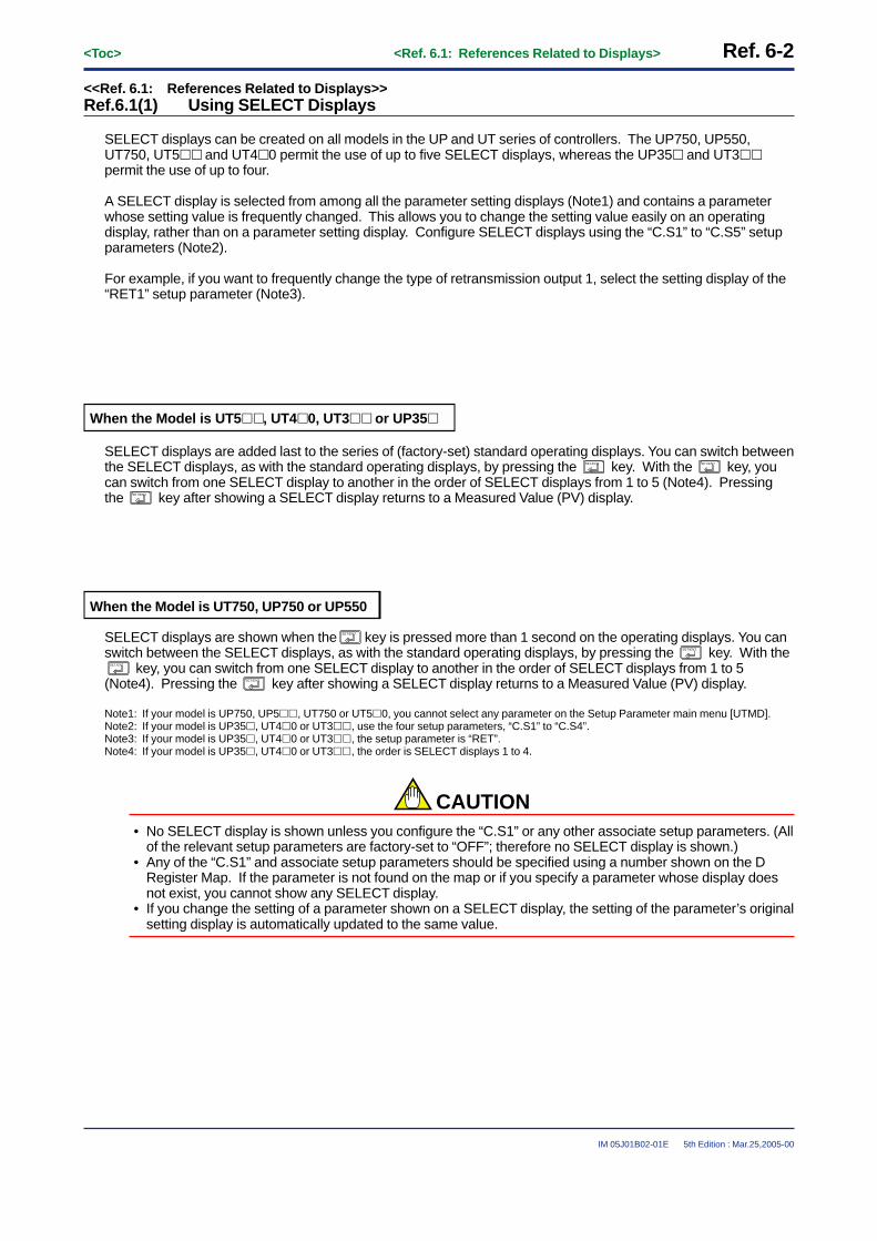
Ref. 6-2<Toc> <Ref. 6.1: References Related to Displays>
IM 05J01B02-01E 5th Edition : Mar.25,2005-00
<<Ref. 6.1: References Related to Displays>>Ref.6.1(1) Using SELECT Displays
SELECT displays can be created on all models in the UP and UT series of controllers. The UP750, UP550,UT750, UT5�� and UT4�0 permit the use of up to five SELECT displays, whereas the UP35� and UT3��permit the use of up to four.
A SELECT display is selected from among all the parameter setting displays (Note1) and contains a parameterwhose setting value is frequently changed. This allows you to change the setting value easily on an operatingdisplay, rather than on a parameter setting display. Configure SELECT displays using the “C.S1” to “C.S5” setupparameters (Note2).
For example, if you want to frequently change the type of retransmission output 1, select the setting display of the“RET1” setup parameter (Note3).
When the Model is UT5��, UT4�0, UT3�� or UP35�
SELECT displays are added last to the series of (factory-set) standard operating displays. You can switch betweenthe SELECT displays, as with the standard operating displays, by pressing the SET/ENT key. With the SET/ENT key, youcan switch from one SELECT display to another in the order of SELECT displays from 1 to 5 (Note4). Pressingthe SET/ENT key after showing a SELECT display returns to a Measured Value (PV) display.
When the Model is UT750, UP750 or UP550
SELECT displays are shown when the SET/ENT key is pressed more than 1 second on the operating displays. You canswitch between the SELECT displays, as with the standard operating displays, by pressing the SET/ENT key. With the
SET/ENT key, you can switch from one SELECT display to another in the order of SELECT displays from 1 to 5(Note4). Pressing the SET/ENT key after showing a SELECT display returns to a Measured Value (PV) display.
Note1: If your model is UP750, UP5��, UT750 or UT5�0, you cannot select any parameter on the Setup Parameter main menu [UTMD].Note2: If your model is UP35�, UT4�0 or UT3��, use the four setup parameters, “C.S1” to “C.S4”.Note3: If your model is UP35�, UT4�0 or UT3��, the setup parameter is “RET”.Note4: If your model is UP35�, UT4�0 or UT3��, the order is SELECT displays 1 to 4.
CAUTION• No SELECT display is shown unless you configure the “C.S1” or any other associate setup parameters. (All
of the relevant setup parameters are factory-set to “OFF”; therefore no SELECT display is shown.)• Any of the “C.S1” and associate setup parameters should be specified using a number shown on the D
Register Map. If the parameter is not found on the map or if you specify a parameter whose display doesnot exist, you cannot show any SELECT display.
• If you change the setting of a parameter shown on a SELECT display, the setting of the parameter’s originalsetting display is automatically updated to the same value.

<Toc> <Ref. 6.1: References Related to Displays> Ref. 6-3
IM 05J01B02-01E 5th Edition : Mar.25,2005-00
Registering SELECT Display
The procedure for registering the SELECT display is as follows.(1) Select a maximum of five parameters to be registered as SELECT displays.
In this example, the three parameters RET1, RTH1 and RTL1 are registered.
● Retransmission Output ParametersLocated in: Main menu = CMLP ; Submenu = RET
Parameter Symbol
Name of Parameter Setting Range and Description
Retransmission output-1 type
OFF: Disable1: PV1, 2: SP1, 3: OUT1, 4: LPS loop power supply (15 V), 5: PV2, 6: SP2, 7: OUT2Setpoints 5 to 7 are not available for single-loop control. Retransmission output 1 is always provided via terminals 14 and 15.
In position proportional control, a valve opening signal (0% to 100%) is transmitted if setpoint “3” is selected.In heating/cooling control, an output value before allocation to heating/cooling control (0% to 100%) is transmitted if setpoint “3” is selected.(0% to 50%: Cooling-side output; 50% to 100%: Heating-side output)
Maximum value of retransmission output-1 scale
RT1=1, 2: TL1 + 1 digit to 100.0% of PV input rangeRT1=3: TL1 + 1 digit to 100.0%RTH1
RET1
Minimum value of retransmission output-1 scale
RT1=1, 2: 0.0% of PV input range to TH1 - 1 digitRT1=3: 0.0% to TH1 - 1 digit
Retransmission output-2 type
Retransmission output-2 is available when the type of control output is not “current” or “voltage pulse.” The output is provided via terminals 16 and 17.OFF: Disable1: PV1, 2: SP1, 3: OUT1, 4: LPS loop power supply (15 V), 5: PV2, 6: SP2, 7: OUT2Setpoints 5 to 7 are not available for single-loop control.
In position proportional control, a valve opening signal (0% to 100%) is transmitted if setpoint “3” is selected.In heating/cooling control, an output value before allocation to heating/cooling control (0% to 100%) is transmitted if setpoint “3” is selected.(0% to 50%: Cooling-side output; 50% to 100%: Heating-side output)
RTL1
RET2
(2) Confirm the D-register numbers of these parameters.The D-register numbers of the parameters used in this example are:
No.10011002100310041005100610071008100910101011101210131014101510161017101810191020
A.BS1(BS1)A.FL1(FL1)A.SR1(SR1)A.LC1(LC1)
A.BS2A.FL2A.SR2A.LC2
A.BS3(BS3)A.FL3(FL3)A.SR3(SR3)A.LC3(LC3)RET1(RT1)RTH1(TH1)RTL1(TL1)RET2(RT2)RTH2(TH2)RTL2(TL2)DVB1(DVB)
10511052105310541055105610571058105910601061106210631064106510661067106810691070
11011102110311041105110611071108110911101111111211131114111511161117111811191120
C.S1C.S2C.S3C.S4C.S5DO1DO2DO3DO4DO5DO6DO7
RDO151RDO152RDO153RDO154RDO155RDO156RDO157RDO158
1001 to No. 1051 to No. 1101 toCMLP
No.11511152115311541155115611571158115911601161116211631164116511661167116811691170
1151 toCONF
RET1:1013RTH1:1014RTL1:1015
● D-register map

Ref. 6-4<Toc> <Ref. 6.1: References Related to Displays>
IM 05J01B02-01E 5th Edition : Mar.25,2005-00
(3) Register the D-register numbers for parameter C.S1 to C.S3, considering the display order of the SELECTdisplays.In this example, the numbers are registered as shown below in order to show the SELECT Displays in theorder of RET1, RTH1, RTL1.
Table 6-1-1
Parameters Setting value
C.S1 1013
C.S2 1014
C.S3 1015
C.S4 OFF
C.S5* OFF
*: UP35� or UT3�� has only four parameters (C.SI to C.S4).
(4) This completes the registration.
● The following parameters are used.Change parameters as explained in the User’s Manuals Initial Settings and Parameter Map.
• Setup parameters (SELECT display Parameters) : C.S1 to C.S5
UP750UP550UT750
Code
Description Setting range
OFF or within the range of D-register numbers(Note2)
1101OFF
Default D-register No.
UP35�UT5�0UT4�0UT3��Code
C.S1 SELECT display-1 registration(C.S1)
1102OFFC.S2 SELECT display-2 registration(C.S2)
1103OFFC.S3 SELECT display-3 registration(C.S3)
1104OFFC.S4 SELECT display-4 registration(C.S4)
1105OFFC.S5 SELECT display-5 registration(C.S5) (Note1)
Note1: UP35�, UT4�0 or UT3�0 does not have a parameter “C.S5”.Note2: With UT3��, UP35�: OFF or 1 to 9999
With UT4�0, UT5��: OFF or 201 to 1039With UT750: OFF or 201 to 1023With UP550, UP750: OFF or 101 to 1023

<Toc> <Ref. 6.1: References Related to Displays> Ref. 6-5
IM 05J01B02-01E 5th Edition : Mar.25,2005-00
<<Ref. 6.1: References Related to Displays>>Ref.6.1(2) Changing Contents of Deviation Trend Display
(for UP750, UP550 and UT750 only)
A Deviation Trend display appears on the UP750, UP550 and UT750. This section explains how to rescale thedeviation trend axis (deviation bandwidth) and/or change the sampling interval.
CAUTION• The Deviation Trend display is factory-set to the following setpoints.
Trend scale of Loop-1 Deviation Trend display:5% of the PV input range spanTrend scale of Loop-2 Deviation Trend display:5% of the PV input range spanTrend time of Deviation Trend display:5 sec.
Do not change these setpoints inadvertently. Otherwise, the trend graph may become difficult to read be-cause of the limited view area, or the trend data may be updated too quickly or slowly. For this reason,change the setpoints, only if necessary, according to the procedure given below.
The deviation trend display uses a chart to show the current deviation trend and can be shown in any controlleroperation mode (UT/UP mode).It shows
1) A single-loop deviation (DV)2) A primary-loop deviation3) A secondary-loop deviation
The following Fig. 6-1-1 Indicates an example of the deviation trend display.
DV2-trend /scan= 20sec+
0
-
Fig. 6-1-1 Example of Deviation Trend Display (with a secondary-loop deviation)
TIP
[When the controller is UP750 or UP550]
The display shows a primary-loop deviation (DV1) when the controller is set up for cascade control (UT mode4) or cascade control with 2 universal inputs (UT mode 13) and in the cascade operation mode, and the CASindicator lamp is lit.The display shows a secondary-loop deviation (DV2) in the secondary-loop Local operationmode.
[When the controller is UT750]
The display shows a primary-loop deviation (DV1) when the controller is set up for cascade control (UT mode4) or cascade control with 2 universal inputs (UT mode 13) and in the cascade operation mode, and the CASindicator lamp is lit.The display shows a secondary-loop deviation (DV2) in the AUTO (automatic) or MAN (manual) operationmode.

Ref. 6-6<Toc> <Ref. 6.1: References Related to Displays>
IM 05J01B02-01E 5th Edition : Mar.25,2005-00
The following procedure explains how to change the contents of a Deviation Trend display.
1) Changes can only be made to the trend scale and/or trend time of the Loop-1 Deviation Trend display.(Note: This procedure also applies to the trend scale of the Loop-2 Deviation Trend display.)
120 dots
0
(+)Trend scale
Trend scale(-)
PresentPast
Fig. 6-1-2 Deviation Trend scale
2) As shown in the figure above, the trend scale of the Loop-1 Deviation Trend display can be set to 0.1 to100.0% of the PV input range span for both positive (+) and negative (-) deviations. The “TSC1” setupparameter is used for this purpose (use “TSC2” for loop 2).
3) As noted above, you can also set the trend time of a Deviation Trend display. The trend time can rangefrom 1 to 600 seconds. At this point, note that the trend data is represented by a maximum of 120 plotsrunning along the time axis. Consequently, the controller can show trend data worth a specified timelength, ranging from a minimum of two minutes (120 sec) to a maximum of 20 hours (72000 sec). Specifythe time length using the “TIM” setup parameter.
TIP
If trend data exceeds 120 plots, all earlier on-screen plots disappear from the display. Trend data is not savedin memory; therefore, there is no way of redisplaying the data once it disappears.
● The following parameters are used.Change parameters as explained in the User’s Manuals Initial Settings and Parameter Map.
• Setup parameters (Deviation Monitor Parameters) : TSC1, TSC2, TIM
UP750UP550UT750Code
Description Setting range
0.1 to 100.0% of PV input range span
10215.0% of PV input range span
Default D-register No.
Deviation trend scale (for loop-1)
10225.0% of PV input range span
Deviation trend scale (for loop-2)
1 to 600 sec. 10235sec.Deviation trend scan time
TSC1
TSC2
TIM
Note1: “TSC2” can be displayed only when the controllers are in the following UT or UP mode.Cascade control, dual-loop control, temperature and humidity control or cascade control with 2 universal inputs.
Note2: “TIM” (deviation trend scan time) is used commonly between “TSC1” and “TSC2”.

<Toc> <Ref. 6.1: References Related to Displays> Ref. 6-7
IM 05J01B02-01E 5th Edition : Mar.25,2005-00
<<Ref. 6.1: References Related to Displays>>Ref.6.1(3) Changing Deviation Display Range of Deviation Monitor
(for UT750, UT550, UT551 and UT450 only)
The deviation monitor is only available with the UT750, UT550, UT551 and UT450. (In other words, the monitor issupported only by controller models whose panel size is 96 mm2 and, therefore, is not available with the UT350.)This section explains how to change the deviation display range (deviation bandwidth) of the deviation monitor.
CAUTION• The deviation display range of the deviation monitor is factory-set to 1% of the PV input range span.
Only if necessary, change the setpoint as instructed below, in accordance with your object of control.
SP + DVB High-limit lamp (yellow) lights when deviation goes over this level.
Normal lamp (green) lightsas long as deviation remains within range.
SP
SP - DVB Low-limit lamp (yellow) lights when deviation goes under this level.
PV
Fig. 6-1-3 Deviation Range
● The following parameters are used.Change parameters as explained in the User’s Manuals Initial Settings and Parameter Map.
• Setup parameters (Deviation Monitor Parameters) : DVB1, DVB2
UT750
Code
Description Setting range
0.0 to 100.0% of PV input range span
10191.0 % of PV input range
Default D-register No.
UT55�UT450
Code
DVB1 Deviation display band (for loop-1)(DVB)
10201.0 % of PV input range
DVB2 Deviation display band (for loop-2)(DV2) (Note1)
Note1: UT450 does not have the parameter “DV2”.

Blank Page

<Toc> <Ref. 7.1: References Related to Security> Ref. 7-1
IM 05J01B02-01E 5th Edition : Mar.25,2005-00
Ref.7.1: References Related to Security
IMPORTANT: Applicable models of this sectionUP750 UP550 UP35� UT750 UT5�� UT4�0 UT3��
UP750-�� UT750-��UP550-�� UP35�-�� UT5��-�� UT4�0-�� UT3��-��
Note: The functions discussed in this section apply to all the models of UT and UP series.However, some of the functions are unavailable with certain models.Such models, if any, will be clearly noted in each of following items from (1) to (2).
This section contains reference information on the following aspects of security. Refer to this information andchange parameters only if necessary.
(1) Setting a password to prevent unauthorized changes to setup parameters(2) Using the keylock function to prevent unauthorized key operation
<<Ref. 7.1: References Related to Security>>Ref.7.1(1) Setting a password to prevent unauthorized changes to setup parameters
A password can be set with all controllers of the UT and UP Series.
By setting a password, you can prevent inadvertent changes to setup parameters. The password is verified whenyou switch from the operating parameter setting display to the setup parameter setting display.
CAUTION• Always remember your password. Once a password has been set, you cannot access the setup parameter
setting display unless you enter the correct password. To cancel your password, the controller must beserviced (for a fee) at a Yokogawa service center.
• Canceling a password reverts all parameters back to their factory-set defaults. For this reason, it is stronglyrecommended to keep a written record of all controller parameter settings.
● The following parameters are used.Change parameters as explained in the User’s Manuals Initial Settings and Parameter Map.
• Setup parameters (Security - related Parameters) : PWD
UP750UP550UT750
Code
Description Setting range
0:Passward not set (Note1)or 1 to 30000 (However, 1 to 9999 with UP35�,UT35� or UT32�)
No register No.0
Default D-register No.
UP35�UT5��UT4�0UT3��Code
PWD Password settig(PWD)
Note: The setpoint 0 means a password has not yet been set. Setting the PWD parameter back to “0” does not enable you to cancel yourcurrent password.

Ref. 7-2<Toc> <Ref. 7.1: References Related to Security>
IM 05J01B02-01E 5th Edition : Mar.25,2005-00
<<Ref. 7.1: References Related to Security>>Ref.7.1(2) Using the keylock function to prevent unauthorized key operation
This function prohibits you from working with the predefined group of operation panel keys during controlleroperation or with the parameter setting display.
CAUTION• The keylock function locks all of the predefined group of operation panel keys.
If any of the panel keys is found to be disabled while correct operation is being carried out in accordancewith the User’s Manual, first check the setpoint of the LOCK parameter.
CAUTION• Even when the keylock function is enabled, relevant key operation is possible with an external contact.
(Operation based on external contacts has priority over key operation. For this reason, it is possible to operate the controller byexternal contact input switching even when keys are locked.)
The keylock function differs depending on the controller model. This section explains the function for each of thefollowing models. Refer to the paragraph that is applicable to your model.
[1] When the Model Is UT35� or UT32�
[2] When the Model Is UT450 or UT420
[3] When the Model Is UT750, UT550, UT551 or UT520
[4] When the Model Is UP35�
[5] When the Model Is UP750 or UP550

<Toc> <Ref. 7.1: References Related to Security> Ref. 7-3
IM 05J01B02-01E 5th Edition : Mar.25,2005-00
[1] When the Model Is UT35� or UT32�
The keylock function of the UT35� and UT32� is as follows. Any one of the function options in Table 7-1-1 can beselected by using the “LOCK” setup parameter.
Table 7-1-1 Keylock Function Options and Their Settings
LOCK Parameter Setting Function
OFF • Turns the keylock function OFF. This is the factory-set default.
1 • Prohibits any parameter setting from being changed.When “1” is selected, no change is allowed to any of the operating and setup parameters; only viewing the parameters is allowed, however. In this case, it is only possible to change the “LOCK” parameter. (Selecting OFF turns the keylock function OFF.)
2 • Prohibits operating parameters from being viewed.The operating parameter setting display is not shown, so settings cannot be changed. The setup parameter setting display can be viewed, however, by holding down the key for more than 3 seconds when an operating display is being shown. (If a password has been set, a password verification display will appear. If the correct password was entered, the setup parameter setting display appears. You can now change the setup parameter setting.)
3 • Disables the key. You are not allowed to switch between auto and manual modes with the front-panel key.
SET/ENT
A/M
A/M
● The following parameters are used.Change parameters as explained in the User’s Manuals Initial Settings and Parameter Map.
• Setup parameters (Security - related Parameters) : LOCK
Description Setting range
OFF: No key lock (turns the key lock function OFF)
1 to 3: (See the Table 7-1-1)
1036OFF
Default D-register No.
UT35�UT32�
Code
Key lock(LOCK)

Ref. 7-4<Toc> <Ref. 7.1: References Related to Security>
IM 05J01B02-01E 5th Edition : Mar.25,2005-00
[2] When the Model Is UT450 or UT420
The keylock function of the UT450 and UT420 works as described in the table below. Two or more options of thekeylock function can be selected using security-related setup parameters.
Table 7-1-2 Keylock Function Options
Keylock Function Option Description
/ keylock • Locks the / keys on the controller front panel to prohibit their operation.However, the password setting or the following security-related parameters setting operation is possible.
key lock • Locks the key on the controller front panel to prohibit switching between auto and manual modes.
Remote/Local mode lock
• The “R/L” operating parameter, which is used to switch between remote and local modes, is not shown.This prohibits you from switching between the two modes by key operation.
PID parameter number lock
• The “PID” operating parameter, which is used to select from the groups 1 to 8 of PID parameters, is not shown. This prohibits you from changing your choice of PID parameters by key operation.
A/MA/M
● The following parameters are used.Change parameters as explained in the User’s Manuals Initial Settings and Parameter Map.
• Setup parameters (Security - related Parameters) : DAT, A/M, R/L, PID
Description Setting range
OFF or ON 1024OFF
Default D-register No.
UT4�0
Code
/ key lock (Data setting key lock)(DAT)
OFF or ON 1025OFF key lock(A/M)
OFF or ON 1028OFFLock of Remote/Local selection parameter(R/L)
OFF or ON 1032OFFLock of parameter for PID parameter display number(PID)
A/M

<Toc> <Ref. 7.1: References Related to Security> Ref. 7-5
IM 05J01B02-01E 5th Edition : Mar.25,2005-00
[3] When the Model Is UT750, UT550, UT551 or UT520
The keylock function of the UT750, UT550, UT551 or UT520 works as described in the table below. Two or moreoptions of the keylock function can be selected using security-related setup parameters.
Table 7-1-3 Keylock Function Options
Keylock Function Option Description
/ keylock • Locks the / keys on the controller front panel to prohibit their operation.However, the password setting or the following security-related parameters setting operation is possible.
key lock • Locks the key on the controller front panel to prohibit switching between auto and manual modes.A/MA/M
Operation mode lock • The parameters in the main menu “MODE,” which are used to select operation mode, are not shown. This prohibits you from making the following changes by key operation.
[USR] operating parameter lock
• The [USR] operating parameter main menu (see Fig. 7-1-1) is not shown. This prohibits you from changing any of the [USR] parameter settings.
2) When the Model Is UT550, UT551, UT520
[PYS1] operating parameter lock (Note2)
• The [PYS1] operating parameter main menu (see Fig. 7-1-1) is not shown. This prohibits you from changing any of the [PYS1] parameter settings.
[PYS2] operating parameter lock (Note3)
• The [PYS2] operating parameter submenu (see Fig. 7-1-1) is not shown. This prohibits you from changing of any of the [PYS2] parameter settings.
• Selecting from auto, manual and cascade modes during cascade control (the parameters are shown only during cascade secondary-loop control, cascade control or cascade control with 2 universal inputs.)
• Switching between loop-1 remote and local modes• Switching between STOP and RUN statuses• Selecting target setpoint number (common to loops 1 and 2)
1) When the Model Is UT750
• Switching between loop-2 auto and manual modes• Selecting from auto, manual and cascade modes during cascade control
(the parameters are shown only during cascade secondary-loop control, cascade control or cascade control with 2 universal inputs.)
• Switching between loop-1 remote and local modes• Switching between loop-2 remote and local modes• Switching between STOP and RUN statuses• Selecting target setpoint number (common to loops 1 and 2)
[LP1] operating parameter lock
• The [LP1] operating parameter main menu (see Fig. 7-1-1) is not shown. This prohibits you from changing any of the [LP1] parameter settings.
[LP2] operating parameter lock (Note1)
• The [LP2] operating parameter main menu (see Fig. 7-1-1) is not shown. This prohibits you from changing any of the [LP2] parameter settings.
[n.PID] operating parameter lock
• The [n.PID] (n = 1 to 8) operating parameter submenu (see Fig. 7-1-1) is not shown. This prohibits you from changing of any of the PID parameter settings by key operation.
Note1: When using a UT mode requiring no secondary loop, such as single-loop control, the controller shows a parameter with which you candecide whether to show or hide the [LP2] or [PYS2] parameter. You need not set the parameter in this case, however.
Note2: With UT5��, the parameter PY1 is used.Note3: With UT5��, the parameter RY2 is used.

Ref. 7-6<Toc> <Ref. 7.1: References Related to Security>
IM 05J01B02-01E 5th Edition : Mar.25,2005-00
SET3S
Operating display
Main menu
Submenu
U3U2U1
+
FLBSSCAT
RTDNRUPR
RFLRBS
ORHORB
ORL
LP1 LP2 USR
PAR 1.PID 7.PID 8.PID
Same as LP1
SET
SET
SET
1.A31.A21.A11.SP
1.I1.P1.A4
1.OH1.D
1.MR1.OL
1.H
1.Pc1.DR
1.Ic
1.Hc1.Dc
1.DB
1.PO1.RP
1.Oc
SET
7.A37.A27.A1
7.I7.P
7.A4
7.OH7.D
7.MR7.OL
7.H
7.Pc7.DR
7.Ic
7.Hc7.Dc
7.DB
7.PORHY
7.Oc
SET
SET
8.A38.A28.A18.SP
8.I8.P
8.A4
8.OH8.D
8.MR8.OL
8.H
8.Pc8.DR
8.Ic
8.Hc8.Dc
8.DB
8.PORDV
8.Oc
SET
MODE
MOD(C.A.M)
SPN
MOD(R/L)MOD(S/R)
orSET3S
+
7.SP
1.B21.A21.B11.A1
1.A41.B31.A3
1.A51.B4
1.A61.B5
1.B6
1.B71.A7
1.A8
1.A91.B8
1.B9
1.BA1.AA
1.AB
1.MD1.BB
2.B22.A22.B12.A1
2.A42.B32.A3
2.A52.B4
2.A62.B5
2.B6
2.B72.A7
2.A8
2.A92.B8
2.B9
2.B102.A10
2.A11
2.MD2.B11
PY2 STUPPY1
SETSET
Password verification
display
SET
To [LOOP1] main menu of setup
parameter setting display
OK
Parameter Map (Example shown for UT550/UT520)
“BS”
For example, locking (hiding) the parameters of the [LP1] main menu further prohibits you from changing the settings of parameters, such as “AT”, that belong to the [RAR] submenu or any of the [1.PID] to [8.PID] submenus.
Fig. 7-1-1
● The following parameters are used.Change parameters as explained in the User’s Manuals Initial Settings and Parameter Map.
• Setup parameters (Security - related Parameters)
Description Setting range
OFF or ON 1024OFF
Default D-register No.
UT5��
Code
(DAT)
OFF or ON 1025OFF(A/M)
OFF or ON 1028OFFOperating parameter main menu [MODE] lock(MOD)
OFF or ON 1030OFFOperating parameter main menu [LP1] lock(LP1)
UT750
Code
�/�
A/M
MODE
LP1
OFF or ON 1031OFFOperating parameter main menu [LP2] lock(LP2)
LP2
OFF or ON 1032OFFOperating parameter main menu [PID] lock(PID)
PID
OFF or ON 1033OFFOperating parameter main menu [USR] lock(USR)
USR
OFF or ON 1034OFFOperating parameter main menu [PYS1] lock(PY1)
PYS1
OFF or ON 1035OFFOperating parameter main menu [PYS2] lock(PY2)
PYS2
/ key lock(data setting key lock)
key lockA/M

<Toc> <Ref. 7.1: References Related to Security> Ref. 7-7
IM 05J01B02-01E 5th Edition : Mar.25,2005-00
[4] When the Model Is UP35�
The keylock function of the UP35� is as follows. Any one of the function options in Table 7-1-4 can be selected byusing the “LOCK” setup parameter.
Table 7-1-4 Keylock Function Options and Their Settings
5 • Disables the key.Prohibits program 1 from starting. (Use this option to prevent program 1 from starting by mistake in an application where, for example, only program 2 needs to be routinely used.)
6 • Disables both the and keys.Prohibits program operation.
7 • Prohibits program 1 parameter settings from being changed.Although program 1 parameters can be viewed on the operating parameter setting display by pressingthe key, you are not allowed to change their settings.
LOCK Parameter Setting Function
OFF • Turns the keylock function OFF. This is the factory-set default.
1 • Prohibits any parameter setting from being changed.When “1” is selected, no change is allowed to any of the operating and setup parameters; only viewing the parameters is allowed, however. In this case, it is only possible to change the “LOCK” parameter. (Selecting OFF turns the keylock function OFF.)
2 • Prohibits operating parameters from being viewed.The operating parameter setting display is not shown, so settings cannot be changed. The setup parameter setting display can be viewed, however, by holding down the key for more than 3 seconds when an operating display is being shown. (If a password has been set, a password verification display will appear. If the correct password was entered, the setup parameter setting display appears. You can now change the setup parameter setting.)
3 • Disables the key. You are not allowed to stop program operation with the front-panel key.
SET/ENT
2 PRG
2 PRG
2 PRG
RESET
RESET
4 • Disables the key.Prohibits program 1 from starting. (Use this option to prevent program 1 from starting by mistake in an application where, for example, only program 2 needs to be routinely used.)
1PRG
1PRG
1PRG
8 • Prohibits program 2 parameter settings from being changed.Although program 2 parameters can be viewed on the operating parameter setting display by pressingthe key, you are not allowed to change their settings.
1PRG 2 PRG
9 • Prohibits both the program 1 parameter settings and program 2 parameter settings from being changed.Although program 1 and / or 2 parameters can be viewed on the operating parameter setting display by pressing the or key, you are not allowed to change their settings.
● The following parameters are used.Change parameters as explained in the User’s Manuals Initial Settings and Parameter Map.
• Setup parameters (Security - related Parameters)
Description Setting range
OFF: No key lock (turns the key lock function OFF)
1 to 9: (See the Table 7-1-4)
10360
Default D-register No.
UP35�
Code
Key lock(LOCK)

Ref. 7-8<Toc> <Ref. 7.1: References Related to Security>
IM 05J01B02-01E 5th Edition : Mar.25,2005-00
[5] When the Model Is UP750 and UP550
The keylock function of the UP750 and UP550 works as described in the table below. Two or more options of thekeylock function can be selected using security-related setup parameters.
Table 7-1-5 Keylock Function Options
Keylock Function Option Description
/ keylock • Locks the / keys on the controller front panel to prohibit their operation.However, the password setting or the following security-related parameters setting operation is possible.
key lock • Locks the key on the controller front panel to prohibit switching Program pattern No..
key lock • Locks the key on the controller front panel.
key lock • Locks the key on the controller front panel.This prohibits you from making the following changes by key operation.
1) When the Model Is UP750
• Switching to hold mode of program operation• Advancing to the next segment during program operation• Starting operation in local mode (with the target setpoint kept constant) • Switching between loop-1auto and manual modes• Switching between loop-2 auto and manual modes (the parameters are shown only during cascade control, dual-loop control,temperature and humidity control, or cascade control with 2 universal inputs)
• Switching between loop-2 local and cascade modes (the parameters are shown only during cascade control or cascade control with 2 universal inputs)
• Selecting starting segment number
[PROG] operating parameter lock
• The [PROG] operating parameter main menu (see Fig. 7-1-2) is not shown. This prohibits you from changing any of the [PROG] parameter settings.
2) When the Model Is UP550
• Switching to hold mode of program operation• Advancing to the next segment during program operation• Starting operation in local mode (with the target setpoint kept constant) • Switching between loop-1auto and manual modes• Switching between loop-2 local and cascade modes (the parameters are shown only during cascade control or cascade control with 2 universal inputs)
• Selecting starting segment number
[USR] operating parameter lock
• The [USR] operating parameter main menu (see Fig. 7-1-2) is not shown. This prohibits you from changing any of the [USR] parameter settings.
[PYS1] operating parameter lock (Note1)
• The [PYS1] operating parameter main menu (see Fig. 7-1-2) is not shown. This prohibits you from changing any of the [PYS1] parameter settings.
[PYS2] operating parameter lock (Note1)
• The [PYS2] operating parameter submenu (see Fig. 7-1-2) is not shown. This prohibits you from changing of any of the [PYS2] parameter settings.
[LP1] operating parameter lock
• The [LP1] operating parameter main menu (see Fig. 7-1-2) is not shown. This prohibits you from changing any of the [LP1] parameter settings.
[LP2] operating parameter lock
• The [LP2] operating parameter main menu (see Fig. 7-1-2) is not shown. This prohibits you from changing any of the [PROG] parameter settings.
[n.PID] operating parameter lock
• The [n.PID] (n = 1 to 8) operating parameter submenu (see Fig. 7-1-2) is not shown. This prohibits you from changing of any of the PID parameter settings by key operation.
MODE MODE
PT.No PT.No
RUN RUN
Note1: When using a UP mode requiring no secondary loop, such as single-loop control, the controller shows a parameter with which you candecide whether to show or hide the [LP2] or [PYS2] parameter. You need not set the parameter in this case, however.

<Toc> <Ref. 7.1: References Related to Security> Ref. 7-9
IM 05J01B02-01E 5th Edition : Mar.25,2005-00
SET3S
Operating display
Main menu
Submenu
U3U2U1
U6U5U4
U8U7
FLBSSCAT
ORLORHORB
S.TM
LP1 LP2 USR
PAR 1.PID 7.PID 8.PID
Same as LP1
SET
SET
SET
1.I1.P
1.OH1.D
1.MR1.OL
1.H
1.Pc1.DR
1.Ic
1.Hc1.Dc
1.DB
1.PO1.RP
1.Oc
SET
7.I7.P
7.OH7.D
7.MR7.OL
7.H
7.Pc7.DR
7.Ic
7.Hc7.Dc
7.DB
7.PORHY
7.Oc
SET
SET
A3A2A1
SET
8.I8.P
8.OH8.D
8.MR8.OL
8.H
8.Pc8.DR
8.Ic
8.Hc8.Dc
8.DB
8.PORDV
8.Oc
PROG
orSET3S
1.b21.a21.b11.a1
1.a41.b31.a3
1.a51.b4
1.a61.b5
1.b6
1.b71.a7
1.a8
1.a91.b8
1.b9
1.b101.a10
1.a11
1.PMD1.b11
2.b22.a22.b12.a1
2.a42.b32.a3
2.a52.b4
2.a62.b5
2.b6
2.b72.a7
2.a8
2.a92.b8
2.b9
2.b102.a10
2.a11
2.PMD2.b11
PYS2 STUPPYS1
SETSET
Password verification
display
SET
To [PARA] main menu of
setup parameter
setting display
OK
Parameter Map (Example shown for UP550)
DISP
DISP
A4
SET
To [LOC] submenu of
program parameter
setting display
AL
To program parameter
map
To setup parameter
map
For example, locking (hiding) the parameters of the [LP1] main menu further prohibits you from changing the settings of parameters, such as “AT”, that belong to the [RAR] submenu or any of the [1.PID] to [8.PID] submenus.
Fig. 7-1-2
● The following parameters are used.Change parameters as explained in the User’s Manuals Initial Settings and Parameter Map.
• Setup parameters (Security - related Parameters)
Description Setting range
OFF or ON 1024OFF
Default D-register No.
OFF or ON 1026OFF[PT.No] key lock
OFF or ON 1028OFF[MODE] key lock
OFF or ON 1030OFFOperating parameter main menu [LP1] lock
UP750UP550
Code
�/�
PT.NO
OFF or ON 1027OFF[RUN] key lockRUN
MODE
LP1
OFF or ON 1031OFFOperating parameter main menu [LP2] lock
LP2
OFF or ON 1032OFFOperating parameter main menu [PID] lock
PID
OFF or ON 1033OFFOperating parameter main menu [USR] lock
USR
OFF or ON 1034OFFOperating parameter main menu [PYS1] lock
PYS1
OFF or ON 1035OFFOperating parameter main menu [PYS2] lock
PYS2
/ key lock(data setting key lock)

Blank Page

<Toc> <Ref. 8.1: Outline of Registers and I - relays> Ref. 8-1
IM 05J01B02-01E 5th Edition : Mar.25,2005-00
Ref.8.1: Outline of Registers and I - relays
IMPORTANT: Applicable models of this sectionUP750 UT750UP550 UP35� UT5�� UT4�0 UT3��
UP750 UT750UP550 UP35� UT5�� UT4�0 UT3��
Note: The “D-registers” and “I-relays” apply to all the models of UT and UP series. However, the kinds of D-registers or “I-relays” differaccording to the controller model. The “B-registers” are used with UP750 or UP550.
These sections below provide outline of Registers and I-relays.Refer to the manual of “LL200 PC-based Custom Computation Building Tool” or the manual of “GREEN SeriesCommunication Function” (Optional) for more details about the functions of registers and I-relays.
(1) Outline of Registers and I-relays(2) D-register Outline and D-register Map(3) B-register Outline and B-register Map(4) I-relay Outline and I-relay Map(5) I-relay Timer setting
CAUTIONThe controller internal data should be destroyed, and do not read or write operation to the Registers or I-relaysin the “unused area.”The “unused area” is shown in each Map of registers or I-relays.For example, any cells left blank for I-relays 1 through 720 ( in the I-relay map) are the “unused area.”

Ref. 8-2<Toc> <Ref. 8.1: Outline of Registers and I - relays>
IM 05J01B02-01E 5th Edition : Mar.25,2005-00
<<Ref.8.1: Outline of Registers and I - relays >>Ref.8.1(1) Outline of Registers and I - relays
With all the GREEN Series controllers, the function of all terminals are specified when the Controller is shippedfrom the factory.Especially with UP750, UP550, UT750, UT550, UT551 and UT520 that can specify a controller mode, the functionof terminals are specified for each controller mode.However, the function of terminals can be changed if necessary. To change them, use the D-registers or I - relays.
When you use the personal computer or the graphic display, centralized watching of control status can be permit-ted with the D-registers.
When you use the function of communication, the Program patterns making are permitted with the B-registers.
Ref.8.1(1) to Ref.8.1(5) show the outline and Registers or I-relays map (list).
Refer to them if necessary.

<Toc> <Ref. 8.1: Outline of Registers and I - relays> Ref. 8-3
IM 05J01B02-01E 5th Edition : Mar.25,2005-00
<<Ref.8.1: Outline of Registers and I - relays >>Ref.8.1(2) D-register Outline and D-register Map
The process data or setting parameters (operating parameters or setup parameters) are kept in the D-registers.
With D-registers, the followings are permitted.
• Registration of SELECT displays (Note1)• Building the User defining area (Note2)• Reading / writing data with the programmable logic controllers ( FA-M3, etc.) (Note3)• Centralized watching of control status with the personal computer or the graphic display. (Note3)
Note1: Refer to Ref.6.1(1) when you want to register SELECT displaysNote2: Only UP750 or UT750 can build the User defining area. Refer to the manual of “LL200 PC-based Custom Computation Building Tool”
for more details.Note3: Refer to the manual of “GREEN series Communication function” (Optional) for more details.
Each D-register has a D-register number.The number of each D-register can be confirmed by the D-register Map. See Table 8-1-2 (the table is for UP750and UP550) to Table 8-1-6 (the table is for UT35� and UT32�).When you want to know the classification of D-registers, see the Table 8-1-1 below.
Table 8-1-1
ClassificationRegister No.
1 to 49
Description
Process values (Note1) Operating display data. PV, SP, OUT values, etc.
50 to 100 User area (Note2) For communication with display.
101 to 200 LOCAL operation parameters
LOCAL setup parameters. Local setpoints, PID numbers, event settings.
201 to 230
Operating parameters
Operation modes and parameters.
A/M, C/A/M, MOUT, etc.
231 to 300 Operation-related parameters. AT, SC, BS, FL, etc.
301 to 800 PID-related parameters. P, I, D, etc.
801 to 900 Message display.Message. Up to 20 alphanumeric characters used
for each message.
901 to 1000
Setup parameters.
Control action parameters. SP, ALM, CTL
1001 to 1100 Common setup parameters. AIN, RET, TRND, LOCK
1101 to 1200 Display, I/O registration parameters. C.SEL, DO, DI, C.PYS
1201 to 1300 UT/UP mode, I/O typeparameters. UPMD, IN, OUT, R485, INIT
1301 to 1500 User defined custom computation area (Note3).
Input block.Block I/O, module output.
1501 to 1700 Output block.
Note1: D-register numbers 1 through 49 are read-only registers.Note2: D-register numbers 50 through 100 (User area) are registers for 16-bit device data those are used with the device like a graphic display.
Do not read or write the data from/to the D-registers in these area when you use the Device like a display.Note3: The D-registers in this area (1301 to 1700) are used with “LL200 PC-based Custom Computation Building Tool” and only UP750 or
UT750 can use them. The data in these area use 0 through 30000 count (0 to 100%) data or flags, or absolute data.

Ref. 8-4<Toc> <Ref. 8.1: Outline of Registers and I - relays>
IM 05J01B02-01E 5th Edition : Mar.25,2005-00
UP750,UP550 D-register Map
Table 8-1-2 (1/4) UP750,UP550 D-register Map (1/4)
PROCESS PROGRAM MODE/PAR OPERATION(1) No. 1~ No. 51~ No. 101~ No. 151~ No. 201~ No. 251~ No. 301~ No. 351~ No. 401~ No. 451~
1 ADERROR 51 101 LSP1 151 201 251 ORH.1 301 351 401 4512 ERROR.1 52 102 LSP1 152 202 252 ORL.1 302 352 402 4523 PV.1 53 103 PIDNO 153 203 253 S.TM 303 353 403 4534 CSP.1 54 104 EV21A 154 204 254 304 354 404 4545 OUT.1 55 105 EV21B 155 205 255 305 355 405 4556 HOUT.1 56 106 EV22A 156 206 256 306 1.P 356 3.P 406 5.P 456 7.P7 COUT.1 57 107 EV22B 157 207 257 307 1.I 357 3.I 407 5.I 457 7.I8 MOD.1 58 108 EV23A 158 208 R/P/L 258 308 1.D 358 3.D 408 5.D 458 7.D9 PIDNO.1 59 109 EV23B 159 209 HOL D 259 309 1.OH 359 3.OH 409 5.OH 459 7.OH10 60 110 EV24A 160 210 ADV 260 310 1.OL 360 3.OL 410 5.OL 460 7.OL11 ALM 61 111 EV24B 161 211 A/M .1 261 311 1.MR 361 3.MR 411 5.MR 461 7.MR12 PVEV 62 112 EV25A 162 212 A/M .2 262 312 1.H 362 3.H 412 5.H 462 7.H13 TM EV1 63 113 EV25B 163 213 LSP/CAS 263 313 1.DR 363 3.DR 413 5.DR 463 7.DR14 TM EV2 64 114 EV26A 164 214 PTNO 264 314 1.Pc 364 3.Pc 414 5.Pc 464 7.Pc15 PTN 65 115 EV26B 165 215 265 315 1.Ic 365 3.Ic 415 5.Ic 465 7.Ic16 SEGNO 66 116 EV27A 166 216 266 316 1.Dc 366 3.Dc 416 5.Dc 466 7.Dc17 TIM E 67 117 EV27B 167 217 MOUT.1 267 317 1.Hc 367 3.Hc 417 5.Hc 467 7.Hc18 ERROR.2 68 118 EV28A 168 218 MOUTc.1 268 318 1.DB 368 3.DB 418 5.DB 468 7.DB19 PV.2 69 119 EV28B 169 219 MOUT.2 269 319 1.RP 369 3.RP 419 5.RP 469 RHY20 CSP.2 70 120 170 220 MOUTc.2 270 320 1.PO 370 3.PO 420 5.PO 470 7.PO21 OUT.2 71 121 171 221 HOLDSP.1 271 AT.2 321 1.Oc 371 3.POc 421 5.Oc 471 7.POc22 HOUT.2 72 122 172 222 HOLDSP.2 272 SC.2 322 372 422 47223 COUT.2 73 123 173 223 HOL DTM 273 BS.2 323 373 423 47324 MOD.2 74 124 174 224 274 FL.2 324 374 424 47425 PIDNO.2 75 125 175 225 275 325 375 425 47526 DEV.1 76 126 176 226 276 326 376 426 47627 OR.1 77 127 177 227 277 327 377 427 47728 78 128 178 228 278 328 378 428 47829 79 129 179 229 279 329 379 429 47930 DEV.2 80 130 180 230 280 ORB.2 330 380 430 48031 OR.2 81 131 181 231 A1
SST
281 ORH.2 331 2.P 381 4.P 431 6.P 481 8.P32 SMEC 82 132 182 232 A2 282 ORL.2 332 2.I 382 4.I 432 6.I 482 8.I33 DISTS 83 133 183 233 A3 283 333 2.D 383 4.D 433 6.D 483 8.D34 RDISTS 84 134 184 234 A4 284 334 2.OH 384 4.OH 434 6.OH 484 8.OH35 PARAERR 85 135 185 235 285 335 2.OL 385 4.OL 435 6.OL 485 8.OL36 ALOSTS 86 136 186 236 286 336 2.MR 386 4.MR 436 6.MR 486 8.MR37 87 137 187 237 287 337 2.H 387 4.H 437 6.H 487 8.H38 88 138 188 238 288 338 2.DR 388 4.DR 438 6.DR 488 8.DR39 DISP1 89 139 189 239 289 339 2.Pc 389 4.Pc 439 6.Pc 489 8.Pc40 DISP2 90 140 190 240 290 340 2.Ic 390 4.Ic 440 6.Ic 490 8.Ic41 TIME 91 141 191 241 AT.1 291 341 2.Dc 391 4.Dc 441 6.Dc 491 8.Dc42 PTNO 92 142 192 242 SC.1 292 342 2.Hc 392 4.Hc 442 6.Hc 492 8.Hc43 SEGNO 93 143 193 243 BS.1 293 343 2.DB 393 4.DB 443 6.DB 493 8.DB44 SEGUSE 94 144 194 244 FL.1 294 344 2.RP 394 4.RP 444 6.RP 494 RDV45 REM.RCY 95 145 195 245 295 345 2.PO 395 4.PO 445 6.PO 495 8.PO46 ALL .RCY 96 146 196 246 296 346 2.POc 396 4.POc 446 6.POc 496 8.POc47 RST 97 147 197 247 297 347 397 447 49748 REN 98 148 198 248 298 348 398 448 49849 PVEOSTS 99 149 199 249 299 349 399 449 49950 100 150 200 250 ORB.1 300 350 400 450 500
unus
ed a
rea
Note: • The code in the square like a “RDISTS” is used only with UP750.• The number attached to the end of code means loop-number. “���.1” indicates that the code is for the loop-1. For example, “CSP.1”
is the code for the loop-1 and “CSP.2” is for the loop-2.• The number attached to the top of code means PID group number. “1.���” indicates that the code is for the PID group-1. For
example, “1.P” is the code for the PID group-1 and “2.P” is for the PID group-2.

<Toc> <Ref. 8.1: Outline of Registers and I - relays> Ref. 8-5
IM 05J01B02-01E 5th Edition : Mar.25,2005-00
Table 8-1-2 (2/4) UP750,UP550 D-register Map (2/4)
OPERATION(2) USR/PY MSG L1/L2 No. 501~ No. 551~ No. 601~ No. 651~ No. 701~ No. 751~ No. 801~ No. 851~ No. 901~ No. 951~501 551 601 651 701 U1 751 2.A1 801 MG10 851 901 951502 552 602 652 702 U2 752 2.B1 802 MG11 852 902 SPT.1 952503 553 603 653 703 U3 753 2.A2 803 MG12 853 903 953504 554 604 654 704 U4 754 2.B2 804 MG13 854 904 TM U.1 954505 555 605 655 705 U5 755 2.A3 805 MG14 855 905 SEG.T 955506 1.P 556 3.P 606 5.P 656 7.P 706 U6 756 2.B3 806 MG15 856 906 PT2.G 956507 1.I 557 3.I 607 5.I 657 7.I 707 U7 757 2.A4 807 MG16 857 907 EHY1 957508 1.D 558 3.D 608 5.D 658 7.D 708 U8 758 2.B4 808 MG17 858 908 EHY2 958509 1.OH 559 3.OH 609 5.OH 659 7.OH 709 759 2.A5 809 MG18 859 909 EHY3 959510 1.OL 560 3.OL 610 5.OL 660 7.OL 710 760 2.B5 810 MG19 860 910 EHY4 960511 1.MR 561 3.MR 611 5.MR 661 7.MR 711 761 2.A6 811 MG20 861 911 EHY5 961512 1.H 562 3.H 612 5.H 662 7.H 712 762 2.B6 812 MG21 862 912 EHY6 962513 1.DR 563 3.DR 613 5.DR 663 7.DR 713 763 2.A7 813 MG22 863 913 EHY7 963514 1.Pc 564 3.Pc 614 5.Pc 664 7.Pc 714 764 2.B7 814 MG23 864 914 EHY8 964515 1.Ic 565 3.Ic 615 5.Ic 665 7.Ic 715 765 2.A8 815 MG24 865 915 AL1.1 965516 1.Dc 566 3.Dc 616 5.Dc 666 7.Dc 716 766 2.B8 816 MG25 866 916 AL2.1 966 OPR.2517 1.Hc 567 3.Hc 617 5.Hc 667 7.Hc 717 767 2.A9 817 MG26 867 917 AL3.1 967 MOD.2518 1.DB 568 3.DB 618 5.DB 668 7.DB 718 768 2.B9 818 MG27 868 918 AL4.1 968 AR.2519 1.RP 569 3.RP 619 5.RP 669 RHY 719 769 2.A10 819 MG28 869 919 HY1.1 969520 1.PO 570 3.PO 620 5.PO 670 7.PO 720 770 2.B10 820 MG29 870 920 HY2.1 970521 1.Oc 571 3.POc 621 5.Oc 671 7.POc 721 771 2.A11 821 MG30 871 921 HY3.1 971522 572 622 672 722 772 2.B11 822 MG31 872 922 HY4.1 972523 573 623 673 723 773 2.PMD 823 MG32 873 923 AM D.1 973 SPH.2
SPL.2524 574 624 674 724 774 824 MG33 874 924 974525 575 625 675 725 775 825 MG34 875 925 975526 576 626 676 726 1.A1 776 826 MG35 876 926 OPR.1 976527 577 627 677 727 1.B1 777 827 MG36 877 927 MOD.1 977528 578 628 678 728 1.A2 778 828 MG37 878 928 AR.1 978529 579 629 679 729 1.B2 779 829 MG38 879 929 ZON 979530 580 630 680 730 1.A3 780 830 MG39 880 930 R.MD 980531 2.P 581 4.P 631 6.P 681 8.P 731 1.B3 781 831 MG40 881 931 R.T
SPH.1SPL.1
PNC
M 981532 2.I 582 4.I 632 6.I 682 8.I 732 1.A4 782 832 MG41 882 932 982533 2.D 583 4.D 633 6.D 683 8.D 733 1.B4 783 833 MG42 883 933 983534 2.OH 584 4.OH 634 6.OH 684 8.OH 734 1.A5 784 834 MG43 884 934 984535 2.OL 585 4.OL 635 6.OL 685 8.OL 735 1.B5 785 835 MG44 885 935 985536 2.MR 586 4.MR 636 6.MR 686 8.MR 736 1.A6 786 836 MG45 886 936 986537 2.H 587 4.H 637 6.H 687 8.H 737 1.B6 787 837 MG46 887 937 987538 2.DR 588 4.DR 638 6.DR 688 8.DR 738 1.A7 788 838 MG47 888 938 988539 2.Pc 589 4.Pc 639 6.Pc 689 8.Pc 739 1.B7 789 839 MG48 889 939 989540 2.Ic 590 4.Ic 640 6.Ic 690 8.Ic 740 1.A8 790 840 MG49 890 940 990541 2.Dc 591 4.Dc 641 6.Dc 691 8.Dc 741 1.B8 791 841 NAM E1 891 941 991542 2.Hc 592 4.Hc 642 6.Hc 692 8.Hc 742 1.A9 792 842 NAM E2 892 942 992543 2.DB 593 4.DB 643 6.DB 693 8.DB 743 1.B9 793 843 NAM E3 893 943 993544 2.RP 594 4.RP 644 6.RP 694 RDV 744 1.A10 794 844 NAM E4 894 944 994545 2.PO 595 4.PO 645 6.PO 695 8.PO 745 1.B10 795 845 NAM E5 895 945 995546 2.POc 596 4.POc 646 6.POc 696 8.POc 746 1.A11 796 846 NAM E6 896 946 996547 597 647 697 747 1.B11 797 847 NAM E7 897 947 997548 598 648 698 748 1.PMD 798 848 NAM E8 898 948 998549 599 649 699 749 799 849 NAM E9 899 949 999550 600 650 700 750 800 850 NAM E10 900 950 1000
unus
ed a
rea
unus
ed a
rea
Note: • The code in the square is used only with UP750.• The number attached to the end of code means loop-number. “���.1” indicates that the code is for the loop-1.• The number attached to the top of code means PID group number. “1.���” indicates that the code is for the PID group-1. For
example, “1.P” is the code for the PID group-1 and “2.P” is for the PID group-2.

Ref. 8-6<Toc> <Ref. 8.1: Outline of Registers and I - relays>
IM 05J01B02-01E 5th Edition : Mar.25,2005-00
Table 8-1-2 (3/4) UP750,UP550 D-register Map (3/4)
CMLP CONF UPMD No. 1001~ No. 1051~ No. 1101~ No. 1151~ No. 1201~ No. 1251~1001 A.BS1 1051 1101 C.S1 1151 ADV 1201 IN1 1251 DLN11002 A.FL1 1052 1102 C.S2 1152 A/M .1 1202 UNI1 1252 ADR11003 A.SR1 1053 1103 C.S3 1153 A/M .2 1203 1253 RP.T11004 A.LC1 1054 1104 C.S4 1154 LSP/CAS 1204 RH1
DP11254 PSL2
1005 A.BS2 1055 1105 C.S5 1155 PTNO.b0 1205 RL1 1255 BPS21006 A.FL2 1056 1106 DO1 1156 PTNO.b1 1206 SDP1 1256 PRI21007 A.SR2 1057 1107 DO2 1157 PTNO.b2 1207 SH1 1257 STP21008 A.LC2 1058 1108 DO3 1158 PTNO.b3 1208 SL1 1258 DLN21009 A.BS3 1059 1109 DO4 1159 PTNO.b4 1209 BSL1 1259 ADR21010 A.FL3 1060 1110 DO5 1160 PTNO.b5 1210 RJC1 1260 RP.T21011 A.SR3 1061 1111 DO6 1161 PTNO.b6 1211 IN2 1261 V.RS1012 A.LC3 1062 1112 DO7 1162 PTNO.b7 1212 UNI2
DP2
DP3
1262 V.L1013 RET1 1063 1113 1163 PTNO.b8 1213 1263 V.H1014 RTH1 1064 1114 1164 DP1 1214 RH2 1264 TR.T1015 RTL1 1065 1115 1165 DP2 1215 RL2 1265 V.M OD1016 RET2 1066 1116 1166 MG1 1216 SDP2 1266 INIT
V.ATA1HA1LA2HA2LA3HA3L
1017 RTH2 1067 1117 1167 MG2 1217 SH2 12671018 RTL2 1068 1118 1168 MG3 1218 SL2 12681019 1069 1119 1169 MG4 1219 BSL2 12691020 1070 1120 1170 PYA1 1220 RJC2 12701021 TSC1 1071 1121 1171 PYB1 1221 IN3 12711022 TSC2 1072 1122 1172 PYA2 1222 UNI3 12721023 TTM 1073 1123 1173 PYB2 1223 12731024 �� 1074 1124 1174 1224 RH3 12741025 1075 1125 1175 1225 RL3 12751026 PT.NO 1076 1126 1176 1226 SDP3 12761027 RUN 1077 1127 1177 1227 SH3 12771028 MODE 1078 1128 1178 1228 SL3 12781029 PRG 1079 1129 1179 1229 BSL3 12791030 LP1 1080 1130 1180 1230 P.UNI1 1280 UPM1031 LP2 1081 1131 1181 1231 P.DP1 1281 SMP1032 PID 1082 1132 1182 1232 P.RH1 12821033 USR 1083 1133 1183 1233 P.RL1 12831034 PYS1 1084 1134 1184 1234 P.UNI2 12841035 PYS2 1085 1135 1185 1235 P.DP2 12851036 1086 1136 1186 1236 P.RH2 12861037 1087 1137 1187 1237 P.RL2 12871038 1088 1138 1188 1238 OT1 12881039 1089 1139 1189 1239 OT2 12891040 1090 1140 1190 1240 CT1 12901041 1091 1141 1191 1241 CT2 12911042 1092 1142 1192 1242 CTc1 12921043 1093 1143 1193 1243 CTc2 12931044 1094 1144 1194 1244 AO1 12941045 1095 1145 1195 1245 AO2 12951046 1096 1146 1196 1246 AO3 12961047 1097 1147 PROG 1197 1247 PSL1 12971048 1098 1148 RESET 1198 1248 BPS1 12981049 1099 1149 LOCAL 1199 1249 PRI1 12991050 1100 1150 HOLD 1200 1250 STP1 1300
RDO151RDO152RDO153RDO154RDO155RDO156RDO157RDO158RDO251RDO252RDO253RDO254RDO255RDO256RDO257RDO258
unus
ed a
rea
unus
ed a
rea
Note: • The code in the square like a “A.BS2” is used only with UP750.• The code in the shaded square like a “V.RS” is used only with UP550.• The number attached to the end of code means loop-number. “���.1” indicates that the code is for the loop-1.• The number attached to the top of code means PID group number. “1.���” indicates that the code is for the PID group-1.

<Toc> <Ref. 8.1: Outline of Registers and I - relays> Ref. 8-7
IM 05J01B02-01E 5th Edition : Mar.25,2005-00
Table 8-1-2 (4/4) UP750,UP550 D-register Map (4/4)
INPUT BLOCK OUTPUT BLOCK No. 1301~ No. 1351~ No. 1401~ No. 1451~ No. 1501~ No. 1551~ No. 1601~ No. 1651~1301 AIN1 1351 1401 MO1L 1451 MO26L 1501 PV.1 1551 1601 MO1L 1651 MO26L1302 AIN2 1352 1402 MO1H 1452 MO26H 1502 PV.2 1552 1602 MO1H 1652 MO26H1303 AIN3 1353 1403 MO2L 1453 MO27L 1503 CSP.1 1553 1603 MO2L 1653 MO27L1304 1354 1404 MO2H 1454 MO27H 1504 CSP.2 1554 1604 MO2H 1654 MO27H1305 1355 1405 MO3L 1455 MO28L 1505 OUT.1 1555 1605 MO3L 1655 MO28L1306 1356 1406 MO3H 1456 MO28H 1506 OUT.2 1556 1606 MO3H 1656 MO28H1307 1357 1407 MO4L 1457 MO29L 1507 HOUT.1 1557 1607 MO4L 1657 MO29L1308 1358 1408 MO4H 1458 MO29H 1508 HOUT.2 1558 1608 MO4H 1658 MO29H1309 1359 1409 MO5L 1459 MO30L 1509 COUT.1 1559 1609 MO5L 1659 MO30L1310 1360 1410 MO5H 1460 MO30H
MO31LMO31HMO32LMO32HMO33LMO33HMO34LMO34HMO35LMO35HMO36LMO36HMO37LMO37HMO38LMO38HMO39LMO39HMO40LMO40HMO41LMO41HMO42LMO42HMO43LMO43HMO44LMO44HMO45LMO45HMO46LMO46HMO47LMO47HMO48LMO48HMO49LMO49HMO50LMO50H
1510 COUT.2 1560 1610 MO5H 1660 MO30H1311 1361 PROG 1411 MO6L 1461 1511 RET1 1561 1611 MO6L 16611312 1362 RESET 1412 MO6H 1462 1512 RET2 1562 1612 MO6H 16621313 1363 LOCAL 1413 MO7L 1463 1513 1563 1613 MO7L 16631314 1364 HOL D 1414 MO7H 1464 1514 1564 1614 MO7H 16641315 1365 ADV 1415 MO8L 1465 1515 1565 1615 MO8L 16651316 1366 A/M .1 1416 MO8H 1466 1516 1566 1616 MO8H 16661317 1367 A/M .2 1417 MO9L 1467 1517 1567 1617 MO9L 16671318 1368 LSP/CAS 1418 MO9H 1468 1518 1568 1618 MO9H 16681319 1369 PTNO.b0 1419 MO10L 1469 1519 1569 1619 MO10L 16691320 1370 PTNO.b1 1420 MO10H 1470 1520 1570 1620 MO10H 16701321 1371 PTNO.b2 1421 MO11L 1471 1521 1571 1621 MO11L 16711322 1372 PTNO.b3 1422 MO11H 1472 1522 1572 1622 MO11H 16721323 1373 PTNO.b4 1423 MO12L 1473 1523 1573 1623 MO12L 16731324 1374 PTNO.b5 1424 MO12H 1474 1524 1574 1624 MO12H 16741325 1375 PTNO.b6 1425 MO13L 1475 1525 1575 1625 MO13L 16751326 1376 PTNO.b7 1426 MO13H 1476 1526 1576 1626 MO13H 16761327 1377 PTNO.b8 1427 MO14L 1477 1527 1577 1627 MO14L 16771328 1378 DP1 1428 MO14H 1478 1528 1578 1628 MO14H 16781329 1379 DP2 1429 MO15L 1479 1529 1579 1629 MO15L 16791330 1380 MG1 1430 MO15H 1480 1530 1580 1630 MO15H 16801331 PVIN.1 1381 MG2 1431 MO16L 1481 1531 OUT1A 1581 1631 MO16L 16811332 PVIN.2 1382 MG3 1432 MO16H 1482 1532 OUT2A 1582 1632 MO16H 16821333 RSPIN.1 1383 MG4 1433 MO17L 1483 1533 OUT3A 1583 1633 MO17L 16831334 RSPIN.2 1384 1434 MO17H 1484 1534 OUT1R 1584 1634 MO17H 16841335 GAIN. 1 1385 1435 MO18L 1485 1535 OUT2R 1585 1635 MO18L 16851336 GAIN. 2 1386 1436 MO18H 1486 1536 DO1 1586 1636 MO18H 16861337 TRG.1 1387 1437 MO19L 1487 1537 DO2 1587 1637 MO19L 16871338 TRG.2 1388 1438 MO19H 1488 1538 DO3 1588 1638 MO19H 16881339 TRF.1 1389 1439 MO20L 1489 1539 DO4 1589 1639 MO20L 16891340 TRF.2 1390 1440 MO20H 1490 1540 DO5 1590 1640 MO20H 16901341 1391 1441 MO21L 1491 1541 DO6 1591 1641 MO21L 16911342 1392 1442 MO21H 1492 1542 DO7DO7
RDO151RDO152RDO153RDO154RDO155RDO156RDO157RDO158
1592 1642 MO21H 16921343 1393 1443 MO22L 1493 1543 1593 1643 MO22L 16931344 1394 1444 MO22H 1494 1544 1594 1644 MO22H 16941345 1395 1445 MO23L 1495 1545 1595 1645 MO23L 16951346 1396 1446 MO23H 1496 1546 1596 1646 MO23H 16961347 1397 1447 MO24L 1497 1547 1597 1647 MO24L 16971348 1398 1448 MO24H 1498 1548 1598 1648 MO24H 16981349 1399 1449 MO25L 1499 1549 1599 1649 MO25L 16991350 1400 1450 MO25H 1500
MO31LMO31HMO32LMO32HMO33LMO33HMO34LMO34HMO35LMO35HMO36LMO36HMO37LMO37HMO38LMO38HMO39LMO39HMO40LMO40HMO41LMO41HMO42LMO42HMO43LMO43HMO44LMO44HMO45LMO45HMO46LMO46HMO47LMO47HMO48LMO48HMO49LMO49HMO50LMO50H1550 1600 1650 MO25H 1700
RDO251RDO252RDO253RDO254RDO255RDO256RDO257RDO258
Note: • The code in the square is used only with UP750.• The number attached to the end of code means loop-number. “���.1” indicates that the code is for the loop-1.• The number attached to the top of code means PID group number. “1.���” indicates that the code is for the PID group-1.

Ref. 8-8<Toc> <Ref. 8.1: Outline of Registers and I - relays>
IM 05J01B02-01E 5th Edition : Mar.25,2005-00
UP35� D-register Map
Table 8-1-3 (1/4) UP35� D-register Map (1/4)
PROCESS PROGRAM MODE/PAR OPERATION(1) OPERATION(2) USR/PY
+0 +100 +200 +300 +400 +500 +600 +700
ADERROR
ERROR
1.P
1.I
MOD R/P1/P2 1.D
PV
CSP
OUT
PIDNO HOLD
ADV
1.MR
PVE
TME
SEGNO
TIME
1.RP
HOLDSP
HOLDTM
1.AL1 2.P
1.A1 2.I
1.AL2 2.D
1.A2
PARAERR 1.EON
1.EOF 2.MR
1.SSP
1.STC
1.SP1
1.TM1
1.SP2 A
PCCH(Note)
PCCL(Note)
T
1.TM2 SC
1.SP3 BS
1.TM3 FL 2.RP
1.SP4
1.TM4
1.SP5
1.TM5
1.SP6
1.TM6
is read only register. is the “User area.”
No
1
2
3
4
5
6
7
8
9
10
11
12
13
14
15
16
17
18
19
20
21
22
23
24
25
26
27
28
29
30
31
32
33
34
35
36
37
38
39
40
41
42
43
44
45
46
47
48
49
50
Note : The codes PCCH and PCCL are used only with UP351.

<Toc> <Ref. 8.1: Outline of Registers and I - relays> Ref. 8-9
IM 05J01B02-01E 5th Edition : Mar.25,2005-00
Table 8-1-3 (2/4) UP35� D-register Map (2/4)
PROCESS PROGRAM MODE/PAR OPERATION(1) OPERATION(2) USR/PY
No +0 +100 +200 +300 +400 +500 +600 +700
51 1.SP7
52 1.TM7
53 1.SP8
54 1.TM8 OH
55 1.SP9 OL
56 1.TM9 HYS 3.P
57 1.SPA DR 3.I
58 1.TMA 3.D
59 1.JC
60 User WIT .Z
61 area 2.AL1 WIT.T 3.MR
62 (50~100) 2.A1
63 2.AL2
64 2.A2
65 2.EON
66 2.EOF
67 2.SSP
68 2.STC
69 2.SP1
70 2.TM1
71 2.SP2
72 2.TM2
73 2.SP3
74 2.TM3
75 2.SP4
76 2.TM4
77 2.SP5
78 2.TM5
79 2.SP6
80 2.TM6
81 2.SP7 4.P
82 2.TM7 4.I
83 2.SP8 4.D
84 2.TM8
85 2.SP9
86 2.TM9 4.MR
87 2.SPA
88 2.TMA
89 2.JC
90
91
92
93
94 RDV
95
96
97
98
99
100
is read only register. is the “User area.”

Ref. 8-10<Toc> <Ref. 8.1: Outline of Registers and I - relays>
IM 05J01B02-01E 5th Edition : Mar.25,2005-00
Table 8-1-3 (3/4) UP35� D-register Map (3/4)
MSG L1/L2 CMLP CONF UPMD
No +800 +900 +1000 +1100 +1200
1 C.S1 IN
2 C.S2 UNI
3 C.S3
4 TMU C.S4 RH
5 SEG.T RL
6 SDP
7 SH
8 SL
9 BSL
10 RJC
11
12
13 RET
14 RTH
15 RTL
16
17
18
19 HY1
20 HY2
21
22
23
24 PO
25
26
27 C.MD
28 AR
29
30
31
32 DIS
33
34
35
36 LO
PCMD(Note)ERJC(Note)
CK
37
38 OT
39
40 CT
41
42
43
44
45
46
47 PSL
48 BPS
49 PRI
50 STP
Note : The codes PCMD and ERJC are used only with UP351.

<Toc> <Ref. 8.1: Outline of Registers and I - relays> Ref. 8-11
IM 05J01B02-01E 5th Edition : Mar.25,2005-00
Table 8-1-3 (4/4) UP35� D-register Map (4/4)
MSG L1/L2 CMLP CONF UPMD
No +800 +900 +1000 +1100 +1200
51 DLN
52 ADR
53 RP.T
54
55
56
57
58
59
60
61
62
63
64
65
66
67
68
69
70
71
72
73
74
75
76
77
78
79
80
81
82
83
84
85
86
87
88
89
90
91
92
93
94
95
96
97
98
99
100

Ref. 8-12<Toc> <Ref. 8.1: Outline of Registers and I - relays>
IM 05J01B02-01E 5th Edition : Mar.25,2005-00
UT750, UT55�, UT520 D-register Map
Table 8-1-4 (1/4) UT750, UT55�, UT520 D-register Map (1/4)
PROCESS PROGRAM MODE/PAR OPERATION(1) No. 1~ No. 51~ No. 101~ No. 151~ No. 201~ No. 251~ No. 301~ No. 351~ No. 401~ No. 451~
1 ADERROR 51 101 151 201 A/M 1 251 ORH.1 301 1.SP 351 3.SP 401 5.SP 451 7.SP2 ERROR.1 52 102 152 202 A/M 2 252 ORL.1 302 1.A1 352 3.A1 402 5.A1 452 7.A13 PV.1 53 103 153 203 R/L1 253 303 1.A2 353 3.A2 403 5.A2 453 7.A24 CSP.1 54 104 154 204 R/L2 254 304 1.A3 354 3.A3 404 5.A3 454 7.A3
PCH.1PCL.1
PCH.2PCL.2
5 OUT.1 55 105 155 205 S/R 255 305 1.A4 355 3.A4 405 5.A4 455 7.A46 HOUT.1 56 106 156 206 C.A.M 256 306 1.P 356 3.P 406 5.P 456 7.P7 COUT.1 57 107 157 207 SPNO(SPN) 257 307 1.I 357 3.I 407 5.I 457 7.I8 MOD.1 58 108 158 208 258 308 1.D 358 3.D 408 5.D 458 7.D9 PIDNO.1 59 109 159 209 259 309 1.OH 359 3.OH 409 5.OH 459 7.OH10 CSPNO 60 110 160 210 260 310 1.OL 360 3.OL 410 5.OL 460 7.OL11 ALM 61 111 161 211 261 311 1.MR 361 3.MR 411 5.MR 461 7.MR12 62 112 162 212 262 312 1.H 362 3.H 412 5.H 462 7.H13 63 113 163 213 263 313 1.DR 363 3.DR 413 5.DR 463 7.DR14 64 114 164 214 264 314 1.Pc 364 3.Pc 414 5.Pc 464 7.Pc15 65 115 165 215 C.RSP.1 265 315 1.Ic 365 3.Ic 415 5.Ic 465 7.Ic16 66 116 166 216 C.RSP.2 266 316 1.Dc 366 3.Dc 416 5.Dc 466 7.Dc17 67 117 167 217 MOUT.1 267 317 1.Hc 367 3.Hc 417 5.Hc 467 7.Hc18 ERROR.2 68 118 168 218 MOUTc.1 268 318 1.DB 368 3.DB 418 5.DB 468 7.DB19 PV.2 69 119 169 219 MOUT.2 269 319 1.RP 369 3.RP 419 5.RP 469 RHY
P.NO
20 CSP.2 70 120 170 220 MOUTc.2 270 320 1.PO 370 3.PO 420 5.PO 470 7.PO21 OUT.2 71 121 171 221 271 AT.2 321 1.Oc 371 3.POc 421 5.Oc 471 7.POc22 HOUT.2 72 122 172 222 272 SC.2 322 372 422 47223 COUT.2 73 123 173 223 273 BS.2 323 373 423 47324 MOD.2 74 124 174 224 274 FL.2 324 374 424 47425 PIDNO.2 75 125 175 225 275 UPR.2 325 375 425 47526 DEV.1 76 126 176 226 276 DNR.2 326 2.SP 376 4.SP 426 6.SP 476 8.SP27 OR.1 77 127 177 227 277 RT.2 327 2.A1 377 4.A1 427 6.A1 477 8.A128 78 128 178 228 278 RBS.2 328 2.A2 378 4.A2 428 6.A2 478 8.A229 79 129 179 229 279 RFL.2 329 2.A3 379 4.A3 429 6.A3 479 8.A330 DEV.2 80 130 180 230 280 ORB.2 330 2.A4 380 4.A4 430 6.A4 480 8.A431 OR.2 81 131 181 231 281 ORH.2 331 2.P 381 4.P 431 6.P 481 8.P32 SMEC(SMC) 82 132 182 232 282 ORL.2 332 2.I 382 4.I 432 6.I 482 8.I33 DISTS 83 133 183 233 283 333 2.D 383 4.D 433 6.D 483 8.D34 RDISTS 84 134 184 234 284 334 2.OH 384 4.OH 434 6.OH 484 8.OH35 PARAERR 85 135 185 235 285 335 2.OL 385 4.OL 435 6.OL 485 8.OL36 ALOSTS 86 136 186 236 286 336 2.MR 386 4.MR 436 6.MR 486 8.MR37 TIM 1 87 137 187 237 287 337 2.H 387 4.H 437 6.H 487 8.H38 TIM 2 88 138 188 238 288 338 2.DR 388 4.DR 438 6.DR 488 8.DR39 DISP1 89 139 189 239 289 339 2.Pc 389 4.Pc 439 6.Pc 489 8.Pc40 DISP2 90 140 190 240 290 340 2.Ic 390 4.Ic 440 6.Ic 490 8.Ic41 91 141 191 241 AT.1 291 341 2.Dc 391 4.Dc 441 6.Dc 491 8.Dc42 92 142 192 242 SC.1 292 342 2.Hc 392 4.Hc 442 6.Hc 492 8.Hc43 93 143 193 243 BS.1 293 343 2.DB 393 4.DB 443 6.DB 493 8.DB44 94 144 194 244 FL.1 294 344 2.RP 394 4.RP 444 6.RP 494 RDV45 95 145 195 245 UPR.1 295 345 2.PO 395 4.PO 445 6.PO 495 8.PO46 96 146 196 246 DNR.1 296 346 2.POc 396 4.POc 446 6.POc 496 8.POc47 97 147 197 247 RT.1 297 347 397 447 49748 98 148 198 248 RBS.1 298 348 398 448 49849 99 149 199 249 RFL.1 299 349 399 449 49950 100 150 200 250 ORB.1 300 350 400 450 500
unus
ed a
rea
Note: • The code in the square like a “RDISTS” is used only with UT750.• The code in the shaded square like a “P.NO” is used only with UT551.• The code in parentheses is for UT550, UT520 and UT551.• The number attached to the end of code means loop-number. “���.1” indicates that the code is for the loop-1. For example, “CSP.1”
is the code for the loop-1 and “CSP.2” is for the loop-2.• The number attached to the top of code means PID group number. “1.���” indicates that the code is for the PID group-1. For
example, “1.SP” is the code for the PID group-1 and “2.SP” is for the PID group-2.

<Toc> <Ref. 8.1: Outline of Registers and I - relays> Ref. 8-13
IM 05J01B02-01E 5th Edition : Mar.25,2005-00
Table 8-1-4 (2/4) UT750, UT55�, UT520 D-register Map (2/4)
OPERATION(2) USR/PY MSG L1/L2 No. 501~ No. 551~ No. 601~ No. 651~ No. 701~ No. 751~ No. 801~ No. 851~ No. 901~ No. 951~501 1.SP 551 3.SP 601 5.SP 651 7.SP 701 U1 751 2.A1 801 MG10 851 901 RMS.1 951502 1.A1 552 3.A1 602 5.A1 652 7.A1 702 U2 752 2.B1 802 MG11 852 902 SPT.1 952503 1.A2 553 3.A2 603 5.A2 653 7.A2 703 U3 753 2.A2 803 MG12 853 903 PVT.1 953504 1.A3 554 3.A3 604 5.A3 654 7.A3 704 U4 754 2.B2 804 MG13 854 904 TM U.1 954505 1.A4 555 3.A4 605 5.A4 655 7.A4 705 U5 755 2.A3 805 MG14 855 905 955 AL1.2506 1.P 556 3.P 606 5.P 656 7.P 706 U6 756 2.B3 806 MG15 856 906 956 AL2.2507 1.I 557 3.I 607 5.I 657 7.I 707 U7 757 2.A4 807 MG16 857 907 957 AL3.2508 1.D 558 3.D 608 5.D 658 7.D 708 U8 758 2.B4 808 MG17 858 908 958 AL4.2509 1.OH 559 3.OH 609 5.OH 659 7.OH 709 759 2.A5 809 MG18 859 909 959 HY1.2510 1.OL 560 3.OL 610 5.OL 660 7.OL 710 760 2.B5 810 MG19 860 910 0 HY2.2511 1.MR 561 3.MR 611 5.MR 661 7.MR 711 761 2.A6 811 MG20 861 911 96
961 HY3.2
512 1.H 562 3.H 612 5.H 662 7.H 712 762 2.B6 812 MG21 862 912 962 HY4.2513 1.DR 563 3.DR 613 5.DR 663 7.DR 713 763 2.A7 813 MG22 863 913 963 AM D.2514 1.Pc 564 3.Pc 614 5.Pc 664 7.Pc 714 764 2.B7 814 MG23 864 914 964515 1.Ic 565 3.Ic 615 5.Ic 665 7.Ic 715 765 2.A8 815 MG24 865 915 AL1.1 965516 1.Dc 566 3.Dc 616 5.Dc 666 7.Dc 716 766 2.B8 816 MG25 866 916 AL2.1 966 OPR.2517 1.Hc 567 3.Hc 617 5.Hc 667 7.Hc 717 767 2.A9 817 MG26 867 917 AL3.1 967 MOD.2518 1.DB 568 3.DB 618 5.DB 668 7.DB 718 768 2.B9 818 MG27 868 918 AL4.1 968 AR.2519 1.RP 569 3.RP 619 5.RP 669 RHY 719 769 2.A10 819 MG28 869 919 HY1.1 969520 1.PO 570 3.PO 620 5.PO 670 7.PO 720 770 2.B10 820 MG29 870 920 HY2.1 970521 1.Oc 571 3.POc 621 5.Oc 671 7.POc 721 771 2.A11 821 MG30 871 921 HY3.1 971522 572 622 672 722 772 2.B11 822 MG31 872 922 HY4.1 972523 573 623 673 723 773 2.PMD 823 MG32 873 923 AM D.1 973524 574 624 674 724 774 824 MG33 874 924 974525 575 625 675 725 775 825 MG34 875 925 975526 2.SP 576 4.SP 626 6.SP 676 8.SP 726 1.A1 776 826 MG35 876 926 OPR.1 976527 2.A1 577 4.A1 627 6.A1 677 8.A1 727 1.B1 777 827 MG36 877 927 MOD.1 977528 2.A2 578 4.A2 628 6.A2 678 8.A2 728 1.A2 778 828 MG37 878 928 AR.1 978529 2.A3 579 4.A3 629 6.A3 679 8.A3 729 1.B2 779 829 MG38 879 929 ZON 979530 2.A4 580 4.A4 630 6.A4 680 8.A4 730 1.A3 780 830 MG39 880 930 R.MD 980531 2.P 581 4.P 631 6.P 681 8.P 731 1.B3 781 831 MG40 881 931 R.T
SPH.1SPH.1DY1.1DY2.1DY3.1DY4.1
GRP
M 981532 2.I 582 4.I 632 6.I 682 8.I 732 1.A4 782 832 MG41 882 932 982533 2.D 583 4.D 633 6.D 683 8.D 733 1.B4 783 833 MG42 883 933 983534 2.OH 584 4.OH 634 6.OH 684 8.OH 734 1.A5 784 834 MG43 884 934 984535 2.OL 585 4.OL 635 6.OL 685 8.OL 735 785 835 MG44 885 935 985536 2.MR 586 4.MR 636 6.MR 686 8.MR 736 1.A6 786 836 MG45 886 936 986537 2.H 587 4.H 637 6.H 687 8.H 737 1.B6
1.B5
787 837 MG46 887 937 987538 2.DR 588 4.DR 638 6.DR 688 8.DR 738 1.A7 788 838 MG47 888 938 988539 2.Pc 589 4.Pc 639 6.Pc 689 8.Pc 739 1.B7 789 839 MG48 889 939 989540 2.Ic 590 4.Ic 640 6.Ic 690 8.Ic 740 1.A8 790 840 MG49 890 940 990541 2.Dc 591 4.Dc 641 6.Dc 691 8.Dc 741 1.B8 791 841 NAM E1 891 941 RMS.2 991542 2.Hc 592 4.Hc 642 6.Hc 692 8.Hc 742 1.A9 792 842 NAM E2 892 942 SPT.2 992543 2.DB 593 4.DB 643 6.DB 693 8.DB 743 1.B9 793 843 NAM E3 893 943 PVT.2 993544 2.RP 594 4.RP 644 6.RP 694 RDV 744 1.A10 794 844 NAM E4 894 944 TM U.2 994545 2.PO 595 4.PO 645 6.PO 695 8.PO 745 1.B10 795 845 NAM E5 895 945 995546 2.POc 596 4.POc 646 6.POc 696 8.POc 746 1.A11 796 846 NAM E6 896 946 996547 597 647 697 747 1.B11 797 847 NAM E7 897 947 997548 598 648 698 748 1.PMD 798 848 NAM E8 898 948 998549 599 649 699 749 799 849 NAM E9 899 949 999550 600 650 700 750 800 850 NAM E10 900 950 1000
SPL.2SPH.2
DY1.2DY2.2DY3.2DY4.2
unus
ed a
rea
unus
ed a
rea
Note: • The code in the square is used only with UT750.• The number attached to the end of code means loop-number. “���.1” indicates that the code is for the loop-1.• The number attached to the top of code means PID group number. “1.���” indicates that the code is for the PID group-1.

Ref. 8-14<Toc> <Ref. 8.1: Outline of Registers and I - relays>
IM 05J01B02-01E 5th Edition : Mar.25,2005-00
Table 8-1-4 (3/4) UT750,UT55�,UT520 D-register Map (3/4)
CMLP CONF UTMD No. 1001~ No. 1051~ No. 1101~ No. 1151~ No. 1201~ No. 1251~1001 A.BS1(BS1) 1051 1101 C.S1 1151 1201 IN1
DP1
DP2
DP3
1251 DLN1(DLN)1002 A.FL1(FL1) 1052 1102 C.S2 1152 1202 UNI1(UN1) 1252 ADR1(ADR)1003 A.SR1(SR1) 1053 1103 C.S3 1153 1203 1253 RP.T1(RP.T)1004 A.LC1(LC1) 1054 1104 C.S4 1154 1204 RH1 1254 PSL21005 A.BS2 1055 1105 C.S5 1155 1205 RL1 1255 BPS21006 A.FL2 1056 1106 DO1 1156 1206 SDP1(DP1) 1256 PRI21007 A.SR2 1057 1107 DO2 1157 1207 SH1 1257 STP21008 A.LC2 1058 1108 DO3 1158 1208 SL1 1258 DLN21009 A.BS3(BS3) 1059 1109 DO4 1159 1209 BSL1(BO1) 1259 ADR21010 A.FL3(FL3) 1060 1110 DO5 1160 1210 RJC1(RJC) 1260 RP.T21011 A.SR3(SR3) 1061 1111 DO6 1161 1211 IN2 1261 V.RS1012 A.LC3(LC3) 1062 1112 DO7 1162 1212 UNI2 1262 V.L1013 RET1(RT1) 1063 1113 RDO151
RDO152RDO153RDO154RDO155RDO156RDO157RDO158RDO251RDO252RDO253RDO254RDO255RDO256RDO257RDO258
1163 1213 1263 V.H1014 RTH1(TH1) 1064 1114 1164 1214 RH2 1264 TR.T
V.ATA1HA1LA2HA2LA3HA3LDPC
1015 RTL1(TL1) 1065 1115 1165 1215 RL2 1265 V.M OD(V.M D)1016 RET2(RT2) 1066 1116 1166 1216 SDP2 1266 INIT (INI)1017 RTH2(TH2) 1067 1117 1167 1217 SH2 12671018 RTL2(TL2) 1068 1118 1168 1218 SL2 12681019 DVB1(DVB) 1069 1119 1169 1219 BSL2 12691020 DVB2(DV2) 1070 1120 1170 1220 RJC2 12701021 TSC1 1071 1121 1171
PYA1(P1A)1221 IN3 1271
1022 TSC2 1072 1122 1172PYB1(P1B)
1222 UNI3(UN3) 12721023 TTM 1073 1123 1173
PYA2(P2A)1223 1273
1024 1074 1124 1174PYB2(P2B)
1224 RH3 12741025 L-A/M
L-MODE
1075 1125 1175 1225 RL3 12751026 1076 1126 1176 1226 SDP3(DP3) 12761027 1077 1127 1177 1227 SH3 12771028 1078 1128 1178 1228 SL3 12781029 1079 1129 A/M .1 1179 1229 BSL3(BO3) 12791030 L-LP1 1080 1130 A/M .2 1180 1230P.UNI1(P.U1) 1280 UTMD1031 L-LP2 1081 1131 R/L.1 1181 1231 P.DP1(P.D1) 1281 SMP1032 L-PID 1082 1132 R/L.2 1182 1232 P.RH1(P.H1) 12821033 L-USR 1083 1133 S/R 1183 1233 P.RL1(P.L1) 12831034 L-PY1 1084 1134 CAS 1184 1234P.UNI2(P.U2) 12841035 L-PY2 1085 1135 AUTO(AUT) 1185 1235 P.DP2(P.D2) 12851036 1086 1136 MA N 1186 1236 P.RH2(P.H2) 12861037 1087 1137 SP.b0 1187 1237 P.RL2(P.L2) 12871038 1088 1138 SP.b1 1188 1238 OT1 12881039 1089 1139 SP.b2 1189 1239 OT2 12891040 1090 1140 SP.b3 1190 1240 CT1 12901041 1091 1141 DP1 1191 1241 CT2 12911042 1092 1142 DP2 1192 1242 CTc1(CTc) 12921043 1093 1143 MG1 1193 1243 CTc2 12931044 1094 1144 MG2 1194 1244 AO1 12941045 1095 1145 MG3 1195 1245 AO2 12951046 1096 1146 MG4 1196 1246 AO3 12961047 1097 1147 1197 1247 PSL1(PSL) 12971048 1098 1148 1198 1248 BPS1(BPS) 12981049 1099 1149 1199 1249 PRI1(PRI) 12991050 1100 1150 1200 1250 STP1(STP) 1300
PIDNO.b0PIDNO.b1PIDNO.b2PIDNO.b3
REM
LCL
PCM.1ERJPCM.2
PRT(Note1)
L-��
unus
ed a
rea
unus
ed a
rea
unus
ed a
rea
Note: • The code in the square like a “A.BS2” is used only with UT750.• The code in the shaded square like a “PCM.1” is used only with UT551.• The code in parentheses is for UT550, UT520 and UT551.• The number attached to the end of code means loop-number. “���.1” indicates that the code is for the loop-1.• The number attached to the top of code means PID group number. “1.���” indicates that the code is for the PID group-1.
Note 1: The code PRT is used only with UT551 with embedded Ethernet.

<Toc> <Ref. 8.1: Outline of Registers and I - relays> Ref. 8-15
IM 05J01B02-01E 5th Edition : Mar.25,2005-00
Table 8-1-4 (4/4) UT750,UT55�,UT520 D-register Map (4/4)
INPUT BLOCK OUTPUT BLOCK No. 1301~ No. 1351~ No. 1401~ No. 1451~ No. 1501~ No. 1551~ No. 1601~ No. 1651~1301 AIN1 1351 SP.b0 1401 MO1L 1451 MO26L 1501 PV.1 1551 1601 MO1L 1651 MO26L1302 AIN2 1352 SP.b1 1402 MO1H 1452 MO26H 1502 PV.2 1552 1602 MO1H 1652 MO26H1303 AIN3 1353 SP.b2 1403 MO2L 1453 MO27L 1503 CSP.1 1553 1603 MO2L 1653 MO27L1304 1354 SP.b3 1404 MO2H 1454 MO27H 1504 CSP.2 1554 1604 MO2H 1654 MO27H1305 1355 DP1 1405 MO3L 1455 MO28L 1505 OUT.1 1555 1605 MO3L 1655 MO28L1306 1356 DP2 1406 MO3H 1456 MO28H 1506 OUT.2 1556 1606 MO3H 1656 MO28H1307 1357 MG1 1407 MO4L 1457 MO29L 1507 HOUT.1 1557 1607 MO4L 1657 MO29L1308 1358 MG2 1408 MO4H 1458 MO29H 1508 HOUT.2 1558 1608 MO4H 1658 MO29H1309 1359 MG3 1409 MO5L 1459 MO30L 1509 COUT.1 1559 1609 MO5L 1659 MO30L1310 1360 MG4 1410 MO5H 1460 MO30H 1510 COUT.2 1560 1610 MO5H 1660 MO30H1311 1361 1411 MO6L 1461 1511 RET1 1561 1611 MO6L 16611312 1362 1412 MO6H 1462 1512 RET2 1562 1612 MO6H 16621313 1363 1413 MO7L 1463 1513 1563 1613 MO7L 16631314 1364 1414 MO7H 1464 1514 1564 1614 MO7H 16641315 1365 1415 MO8L 1465 1515 1565 1615 MO8L 16651316 1366 1416 MO8H 1466 1516 1566 1616 MO8H 16661317 1367 1417 MO9L 1467 1517 1567 1617 MO9L 16671318 1368 1418 MO9H 1468 1518 1568 1618 MO9H 16681319 1369 1419 MO10L 1469 1519 1569 1619 MO10L 16691320 1370 1420 MO10H 1470 1520 1570 1620 MO10H 16701321 1371 1421 MO11L 1471 1521 1571 1621 MO11L 16711322 1372 1422 MO11H 1472 1522 1572 1622 MO11H 16721323 1373 1423 MO12L 1473 1523 1573 1623 MO12L 16731324 1374 1424 MO12H 1474 1524 1574 1624 MO12H 16741325 1375 1425 MO13L 1475 1525 1575 1625 MO13L 16751326 1376 1426 MO13H 1476 1526 1576 1626 MO13H 16761327 1377 1427 MO14L 1477 1527 1577 1627 MO14L 16771328 1378 1428 MO14H 1478 1528 1578 1628 MO14H 16781329 1379 1429 MO15L 1479 1529 1579 1629 MO15L 16791330 1380 1430 MO15H 1480 1530 1580 1630 MO15H 16801331 PVIN.1 1381 1431 MO16L 1481 1531 OUT1A 1581 1631 MO16L 16811332 PVIN.2 1382 1432 MO16H 1482 1532 OUT2A 1582 1632 MO16H 16821333 RSPIN.1 1383 1433 MO17L 1483 1533 OUT3A 1583 1633 MO17L 16831334 RSPIN.2 1384 1434 MO17H 1484 1534 OUT1R 1584 1634 MO17H 16841335 GAIN.1 1385 1435 MO18L 1485 1535 OUT2R 1585 1635 MO18L 16851336 GAIN.2 1386 1436 MO18H 1486 1536 DO1 1586 1636 MO18H 16861337 TRG.1 1387 1437 MO19L 1487 1537 DO2 1587 1637 MO19L 16871338 TRG.2 1388 1438 MO19H 1488 1538 DO3 1588 1638 MO19H 16881339 TRF.1 1389 1439 MO20L 1489 1539 DO4 1589 1639 MO20L 16891340 TRF.2 1390 1440 MO20H 1490 1540 DO5 1590 1640 MO20H 16901341 1391 1441 MO21L 1491 1541 DO6 1591 1641 MO21L 16911342 1392 1442 MO21H 1492 1542 DO7 1592 1642 MO21H 16921343 A/M .1 1393 1443 MO22L 1493 1543 1593 1643 MO22L 16931344 A/M .2 1394 1444 MO22H 1494 1544 1594 1644 MO22H 16941345 R/L.1 1395 1445 MO23L 1495 1545 1595 1645 MO23L 16951346 R/L.2 1396 1446 MO23H 1496 1546 1596 1646 MO23H 16961347 S/R 1397 1447 MO24L 1497 1547 1597 1647 MO24L 16971348 CAS 1398 1448 MO24H 1498 1548 1598 1648 MO24H 16981349 AUTO 1399 1449 MO25L 1499 1549 1599 1649 MO25L 16991350 MA N 1400 1450 MO25H 1500 1550 1600 1650 MO25H 1700
MO31LMO31HMO32LMO32HMO33LMO33HMO34LMO34HMO35LMO35HMO36LMO36HMO37LMO37HMO38LMO38HMO39LMO39HMO40LMO40HMO41LMO41HMO42LMO42HMO43LMO43HMO44LMO44HMO45LMO45HMO46LMO46HMO47LMO47HMO48LMO48HMO49LMO49HMO50LMO50H
MO31LMO31HMO32LMO32HMO33LMO33HMO34LMO34HMO35LMO35HMO36LMO36HMO37LMO37HMO38LMO38HMO39LMO39HMO40LMO40HMO41LMO41HMO42LMO42HMO43LMO43HMO44LMO44HMO45LMO45HMO46LMO46HMO47LMO47HMO48LMO48HMO49LMO49HMO50LMO50H
RDO151RDO152RDO153RDO154RDO155RDO156RDO157RDO158
RDO251RDO252RDO253RDO254RDO255RDO256RDO257RDO258
Note: • The code in the square is used only with UT750.• The number attached to the end of code means loop-number. “���.1” indicates that the code is for the loop-1.• The number attached to the top of code means PID group number. “1.���” indicates that the code is for the PID group-1.

Ref. 8-16<Toc> <Ref. 8.1: Outline of Registers and I - relays>
IM 05J01B02-01E 5th Edition : Mar.25,2005-00
UT450,UT420 D-register Map
Table 8-1-5 (1/3) UT450,UT420 D-register Map (1/3)
PROCESS PROGRAM MODE/PAR OPERATION(1) No. 1~ No. 51~ No. 101~ No. 151~ No. 201~ No. 251~ No. 301~ No. 351~ No. 401~ No. 451~
1 51 101 151 201 251 ORH 301 1.SP 351 3.SP 401 5.SP 451 7.SP2 52 102 152 202 252 ORL 302 352 402 4523 53 103 153 203 253 303 353 403 4534 54 104 154 204 254 304 354 404 4545 55 105 155 205 255 305 355 405 4556 56 106 156 206 256 306 1.P 356 3.P 406 5.P 456 7.P7 57 107 157 207 257 307 1.I 357 3.I 407 5.I 457 7.I8 58 108 158 208 258 308 1.D 358 3.D 408 5.D 458 7.D9 59 109 159 209 259 309 1.OH 359 3.OH 409 5.OH 459 7.OH10 60 110 160 210 260 310 1.OL 360 3.OL 410 5.OL 460 7.OL11 61 111 161 211 261 311 1.MR 361 3.MR 411 5.MR 461 7.MR12 62 112 162 212 262 312 1.H 362 3.H 412 5.H 462 7.H13 63 113 163 213 263 313 1.DR 363 3.DR 413 5.DR 463 7.DR14 64 114 164 214 264 314 1.Pc 364 3.Pc 414 5.Pc 464 7.Pc15 65 115 165 215 265 315 1.Ic 365 3.Ic 415 5.Ic 465 7.Ic16 66 116 166 216 266 316 1.Dc 366 3.Dc 416 5.Dc 466 7.Dc17 67 117 167 217 267 317 1.Hc 367 3.Hc 417 5.Hc 467 7.Hc18 68 118 168 218 268 318 1.DB 368 3.DB 418 5.DB 468 7.DB19 69 119 169 219 269 319 1.RP 369 3.RP 419 5.RP 469 RHY20 70 120 170 220 270 320 1.PO 370 3.PO 420 5.PO 470 7.PO21 71 121 171 221 271 321 1.Oc 371 3.POc 421 5.Oc 471 7.POc22 72 122 172 222 272 322 372 422 47223 73 123 173 223 273 323 373 423 47324 74 124 174 224 274 324 374 424 47425 75 125 175 225 275 325 375 425 47526 76 126 176 226 276 326 2.SP 376 4.SP 426 6.SP 476 8.SP27 77 127 177 227 277 327 377 427 47728 78 128 178 228 278 328 378 428 47829 79 129 179 229 279 329 379 429 47930 80 130 180 230 280 330 380 430 48031 81 131 181 231 281 331 2.P 381 4.P 431 6.P 481 8.P32 82 132 182 232 282 332 2.I 382 4.I 432 6.I 482 8.I33 83 133 183 233 283 333 2.D 383 4.D 433 6.D 483 8.D34 84 134 184 234 284 334 2.OH 384 4.OH 434 6.OH 484 8.OH35 85 135 185 235 285 335 2.OL 385 4.OL 435 6.OL 485 8.OL36 86 136 186 236 286 336 2.MR 386 4.MR 436 6.MR 486 8.MR37 87 137 187 237 287 337 2.H 387 4.H 437 6.H 487 8.H38
ADERRORERROR
PVCSPOUT
HOUTCOUTMOD
PIDNOCSPNO
ALM
DEVOR
DISTS
PARAERRALOSTS
TIM1TIM2 88 138 188 238 288 338 2.DR 388 4.DR 438 6.DR 488 8.DR
39 89 139 189 239 289 339 2.Pc 389 4.Pc 439 6.Pc 489 8.Pc40 90 140 190 240 290 340 2.Ic 390 4.Ic 440 6.Ic 490 8.Ic41 91 141 191 241 291 341 2.Dc 391 4.Dc 441 6.Dc 491 8.Dc42 92 142 192 242 292 342 2.Hc 392 4.Hc 442 6.Hc 492 8.Hc43 93 143 193 243 293 343 2.DB 393 4.DB 443 6.DB 493 8.DB44 94 144 194 244 294 344 2.RP 394 4.RP 444 6.RP 494 RDV45 95 145 195 245 295 345 2.PO 395 4.PO 445 6.PO 495 8.PO46 96 146 196 246 296 346 2.POc 396 4.POc 446 6.POc 496 8.POc47 97 147 197 247 297 347 397 447 49748 98 148 198 248 298 348 398 448 49849 99 149 199 249 299 349 399 449 49950 100 150 200 250
A/M
R/L
S/R
SPN
C.RSP
MOUTMOUTc
A1A2A3A4
ATSCBSFL
UPRDNRRT
RBSRFLORB 300 350 400 450 500

<Toc> <Ref. 8.1: Outline of Registers and I - relays> Ref. 8-17
IM 05J01B02-01E 5th Edition : Mar.25,2005-00
Table 8-1-5 (2/3) UT450,UT420 D-register Map (2/3)
OPERATION(2) USR/PY MSG L1/L2 No. 501~ No. 551~ No. 601~ No. 651~ No. 701~ No. 751~ No. 801~ No. 851~ No. 901~ No. 951~501 551 601 651 701 751 801 851 901 951502 552 602 652 702 752 802 852 902 952503 553 603 653 703 753 803 853 903 953504 554 604 654 704 754 804 854 904 954505 555 605 655 705 755 805 855 905 955506 556 606 656 706 756 806 856 906 956507 557 607 657 707 757 807 857 907 957508 558 608 658 708 758 808 858 908 958509 559 609 659 709 759 809 859 909 959510 560 610 660 710 760 810 860 910 960511 561 611 661 711 761 811 861 911 961512 562 612 662 712 762 812 862 912 962513 563 613 663 713 763 813 863 913 963514 564 614 664 714 764 814 864 914 964515 565 615 665 715 765 815 865 915 965516 566 616 666 716 766 816 866 916 966517 567 617 667 717 767 817 867 917 967518 568 618 668 718 768 818 868 918 968519 569 619 669 719 769 819 869 919 969520 570 620 670 720 770 820 870 920 970521 571 621 671 721 771 821 871 921 971522 572 622 672 722 772 822 872 922 972523 573 623 673 723 773 823 873 923 973524 574 624 674 724 774 824 874 924 974525 575 625 675 725 775 825 875 925 975526 576 626 676 726 776 826 876 926 976527 577 627 677 727 777 827 877 927 977528 578 628 678 728 778 828 878 928 978529 579 629 679 729 779 829 879 929 979530 580 630 680 730 780 830 880 930 D 980531 581 631 681 731 781 831 881 931
RMSSPTPVTTMU
AL1AL2AL3AL4HY1HY2HY3HY4AMD
OPRMODAR
ZONR.M
R.TMDISSPHSPLDY1DY2DY3DY4
GRP
981532 582 632 682 732 782 832 882 932 982533 583 633 683 733 783 833 883 933 983534 584 634 684 734 784 834 884 934 984535 585 635 685 735 785 835 885 935 985536 586 636 686 736 786 836 886 936 986537 587 637 687 737 787 837 887 937 987538 588 638 688 738 788 838 888 938 988539 589 639 689 739 789 839 889 939 989540 590 640 690 740 790 840 890 940 990541 591 641 691 741 791 841 891 941 991542 592 642 692 742 792 842 892 942 992543 593 643 693 743 793 843 893 943 993544 594 644 694 744 794 844 894 944 994545 595 645 695 745 795 845 895 945 995546 596 646 696 746 796 846 896 946 996547 597 647 697 747 797 847 897 947 997548 598 648 698 748 798 848 898 948 998549 599 649 699 749 799 849 899 949 999550 600 650 700 750 800 850 900 950 1000

Ref. 8-18<Toc> <Ref. 8.1: Outline of Registers and I - relays>
IM 05J01B02-01E 5th Edition : Mar.25,2005-00
Table 8-1-5 (3/3) UT450,UT420 D-register Map (3/3)
CMLP CONF UTMD No. 1001~ No. 1051~ No. 1101~ No. 1151~ No. 1201~ No. 1251~1001 1051 1101 C.S1 1151 1201 IN 1251 DLN1002 1052 1102 C.S2 1152 1202 UNI 1252 ADR1003 1053 1103 C.S3 1153 1203 1253 RP.T1004 1054 1104 C.S4 1154 1204 RH 12541005 1055 1105 C.S5 1155 1205 RL 12551006 1056 1106 1156 1206 SDP 12561007 1057 1107 1157 1207 SH 12571008 1058 1108 1158 1208 SL 12581009 1059 1109 1159 1209 BSL 12591010 1060 1110 1160 1210 RJC 12601011 1061 1111 1161 1211 1261 V.RS1012 1062 1112 1162 1212 1262 V.L1013 RET1 1063 1113 1163 1213 1263 V.H1014 RTH1 1064 1114 1164 1214 1264 TR.T1015 RTL1 1065 1115 1165 1215 1265 V.MOD
V.AT1016 1066 1116 1166 1216 1266 INI
DPC
1017 1067 1117 1167 1217 12671018 1068 1118 1168 1218 12681019 DVB1 1069 1119 1169 1219 12691020 1070 1120 1170 1220 12701021 1071 1121 1171 1221 RSP 12711022 1072 1122 1172 1222 12721023 1073 1123 1173 1223 12731024 L-�� 1074 1124 1174 1224 12741025 L-A/M 1075 1125 1175 1225 12751026 1076 1126 1176 1226 12761027 1077 1127 1177 1227 RSH 12771028 L-R/L 1078 1128 1178 1228 RSL 12781029 1079 1129 1179 1229 12791030 1080 1130 1180 1230 12801031 1081 1131 1181 1231 12811032 L-PID 1082 1132 1182 1232 12821033 1083 1133 1183 1233 12831034 1084 1134 1184 1234 12841035 1085 1135 1185 1235 12851036 1086 1136 1186 1236 12861037 1087 1137 1187 1237 12871038 1088 1138 1188 1238 OT 12881039 1089 1139 1189 1239 12891040 1090 1140 1190 1240 CT 12901041 1091 1141 1191 1241 12911042 1092 1142 1192 1242 CTc 12921043 1093 1143 1193 1243 12931044 1094 1144 1194 1244 12941045 1095 1145 1195 1245 12951046 1096 1146 1196 1246 12961047 1097 1147 1197 1247 PSL 12971048 1098 1148 1198 1248 BPS 12981049 1099 1149 1199 1249 PRI 12991050 1100 1150 1200 1250 STP 1300

<Toc> <Ref. 8.1: Outline of Registers and I - relays> Ref. 8-19
IM 05J01B02-01E 5th Edition : Mar.25,2005-00
UT35�, UT32� D-register Map
Table 8-1-6 (1/4) UT35�,UT32� D-register Map (1/4)
PROCESS PROGRAM MODE/PAR OPERATI ON(1) OPERATI ON(2) USR/PY
No +0 +100 +200 +300 +400 +500 +600 +700
1 ADERROR A/M 1.SP
2 ERROR
3
4
5
6 1.P
7 SPN
S/R
O 1.I
8
PV
CSP
OUT
HOUT
COUT
MOD 1.D
9 PIDNO
10 CSPNO
11 ALM 1.MR
12
13
14 1.Pc
15 C.RSP 1.Ic
16 1.Dc
17 MOUTH
18 MOUTC 1.DB
19 1.RP
20
21
22
23
24
25
26 2.SP
27 OR
28 HBC1
29 HBC2
30
31 A1 2.P
32 A2 2.I
33 A
PCCH(Note)
PCCL(Note)
3 2.D
34
35 PARAERR
36 2.MR
37
38
39 2.Pc
40 2.Ic
41 AT 2.Dc
42 SC
43 BS 2.DB
44 FL 2.RP
45 UPR
46 DNR
47
48
49
50 ORB
is read only register. is the “User area.”
Note: The codes PCCH and PCCL are used only with UT351 and UT321.

Ref. 8-20<Toc> <Ref. 8.1: Outline of Registers and I - relays>
IM 05J01B02-01E 5th Edition : Mar.25,2005-00
Table 8-1-6 (2/4) UT35�,UT32� D-register Map (2/4)
PROCESS PROGRAM MODE/PAR OPERATION(1) OPERATION(2) USR/PY
No +0 +100 +200 +300 +400 +500 +600 +700
51 ORH 3.SP
52 ORL
53
54 OH
55 OL
56 UYS 3.P
57 DR 3.I
58 HB1 3.D
59 HB2
60 User
61 area 3.MR
62 (50-100)
63
64 3.Pc
65 3.Ic
66 3.Dc
67
68 3.DB
69
70
71
72
73
74
75
76 4.SP
77
78
79
80
81 4.P
82 4.I
83 4.D
84
85
86 4.MR
87
88
89 4.Pc
90 4.Ic
91 4.Dc
92
93 4.DB
94 RDV
95
96
97
98
99
100
is read only register. is the “User area.”

<Toc> <Ref. 8.1: Outline of Registers and I - relays> Ref. 8-21
IM 05J01B02-01E 5th Edition : Mar.25,2005-00
Table 8-1-6 (3/4) UT35�,UT32� D-register Map (3/4)
MSG L1/L2 CMLP CONF UTMD
No +800 +900 +1000 +1100 +1200
1 C.S1 IN
2 C.S2 UNI
3 C.S3
4 TMU C.S4 RH
5 RL
6 SDP
7 SH
8 SL
9 BSL
10 RJC
11
12
13 RET
14 RTH
15 AL1 RTL
16 AL2
17 AL3
18
19 HY1
20 HY2
21 HY3
22
23
24 PO
25 POc
26
27 C.MD
28 AR
29 ZON
30
31
32 DIS
33
34
35
36 LO
PCMD(Note)ERJC(Note)
CK
37
38 OT
39
40 CT
41
42 CTc
43
44
45
46
47 PSL
48 BPS
49 PRI
50 STP
Note : The codes PCMD and ERJC are used only with UT351 and UT321.

Ref. 8-22<Toc> <Ref. 8.1: Outline of Registers and I - relays>
IM 05J01B02-01E 5th Edition : Mar.25,2005-00
Table 8-1-6 (4/4) UT35�,UT32� D-register Map (4/4)
MSG L1/L2 CMLP CONF UTM D
No +800 +900 +100
PRT(Note)
0 +1100 +1200
51 DLN
52 ADR
53 RP.T
54
55
56
57
58
59
60
61
62
63
64
65
66
67
68
69
70
71
72
73
74
75
76
77
78
79
80
81
82
83
84
85
86
87
88
89
90
91
92
93
94
95
96
97
98
99
100
Note : The code PRT is used only with UT351 with embedded Ethernet.

<Toc> <Ref. 8.1: Outline of Registers and I - relays> Ref. 8-23
IM 05J01B02-01E 5th Edition : Mar.25,2005-00
<<Ref.8.1: Outline of Registers and I - relays >>Ref.8.1(3) B-register Outline and B-register Map
Only UP750 or UT750 use the B-registers.
When you use the function of communication, the making of Program patterns are permitted with the B-registers.Refer to the manual of “Communication function” (Optional) for more details.
Each B-register has a B-register number.The number of each B-register can be confirmed by the B-register Map (See Table 8-1-8).When you want to know the classification of B-registers, see the Table 8-1-7 below.
Table 8-1-7
1 to 100
101 to 140
1301 to 1600
Program pattern read/write operation
Segment information read/write operation
99 segments TSP value
Register No. Classification Description
Start target setpoint, wait function, repeat function, etc.
Event function, etc.
Target setpoint, etc.
1602 to 1700 99 segments segment time (TIME)Segment time (time setting or ratio setting)[Use “SEG.T” parameter]

Ref. 8-24<Toc> <Ref. 8.1: Outline of Registers and I - relays>
IM 05J01B02-01E 5th Edition : Mar.25,2005-00
UP750,UP550 B-register Map
Table 8-1-8 (1/2) UP750,UP550 B-register Map (1/2)
PTNWR SEGWR No. 1~ No. 51~ No. 101~ No. 151~
1 PTNO 51 101 1512 SEGNO 52 102 1523 RDTRG 53 103 RDTRG 1534 WRTRG 54 104 WRTRG 1545 RTN.ERR 55 105 PTN.ERR 1556 56 106 1567 57 107 1578 SEG 58 108 SEG 1589 EV 59 109 EV 15910 PTN.SEG 60 110 PTN.SEG 16011 SSP1 61 PTNO-A 111 TSP1 16112 SSP2 62 PTNO-B 112 TSP2 16213 STC 63 PTE-TRG 113 TIM E 16314 1.WZ1 64 PTC-TRG 114 TM .RT 16415 1.WZ2 65 PTN.ERR 115 PIDNO 16516 1.WTM 66 116 EV1 16617 2.WZ1 67 117 ON1 or TY1 16718 2.WZ2 68 118 OFF1 or PE1 16819 2.WTM 69 119 EV2 16920 3.WZ1 70 120 ON2 or TY2 17021 3.WZ2 71 121 OFF2 or PE2 17122 3.WTM 72 122 EV3 17223 4.WZ1 73 123 ON3 or TY3 17324 4.WZ2 74 124 OFF3 or PE3 17425 4.WTM 75 125 EV4 17526 5.WZ1 76 126 ON4 or TY4 17627 5.WZ2 77 127 OFF4 or PE4 17728 5.WTM 78 128 EV5 17829 RCY 79 129 ON5 or TY5 17930 RST 80 130 OFF5 or PE5 18031 REN 81 PTN.USE1 131 EV6 18132 82 PTN.USE2 132 ON6 or TY6 18233 83 PTN.USE3 133 OFF6 or PE6 18334 84 PTN.USE4 134 EV7 18435 85 PTN.USE5 135 ON7 or TY7 18536 86 PTN.USE6 136 OFF7 or PE7 18637 87 PTN.USE7 137 EV8 18738 88 PTN.USE8 138 ON8 or TY8 18839 89 PTN.USE9 139 OFF8 or PE8 18940 P.NAM E1 90 PTN.USE10 140 JC 19041 P.NAM E2 91 PTN.USE11 141 19142 P.NAM E3 92 PTN.USE12 142 19243 P.NAM E4 93 PTN.USE13 143 19344 P.NAM E5 94 PTN.USE14 144 19445 P.NAM E6 95 PTN.USE15 145 19546 P.NAM E7 96 PTN.USE16 146 19647 P.NAM E8 97 PTN.USE17 147 19748 P.NAM E9 98 PTN.USE18 148 19849 P.NAM E10 99 PTN.USE19 149 19950 100 150 200
rem.rem.
rem.rem.
Note: • The code in the square like a “1.WZ2” is used only with UP750.• Other codes are common to UP750 and UP550.

<Toc> <Ref. 8.1: Outline of Registers and I - relays> Ref. 8-25
IM 05J01B02-01E 5th Edition : Mar.25,2005-00
Table 8-1-8 (2/2) UP750,UP550 B-register Map (2/2)
TSPTG TSP1 TSP2 No. 1301~ No. 1351~ No. 1401~ No. 1451~ No. 1501~ No. 1551~1301 PTNO 1351 1401 SSP1 1451 TSP1. .
.
50 1501 SSP2 1551 TSP2.501302 1352 1402 TSP1.1 1452 TSP1.51 1502 TSP2.1 1552 TSP2.511303 RDTRG
WR.TRGPTN.ERR
1353 1403 TSP1.2 1453 TSP1.52 1503 TSP2.2 1553 TSP2.521304 1354 1404 TSP1.3 1454 TSP1.53 1504 TSP2.3 1554 TSP2.531305 1355 1405 TSP1.4 1455 TSP1.54 1505 TSP2.4 1555 TSP2.541306 1356 1406 TSP1.5 1456 TSP1.55 1506 TSP2.5 1556 TSP2.551307 1357 1407 TSP1.6 1457 TSP1.56 1507 TSP2.6 1557 TSP2.561308 1358 1408 TSP1.7 1458 TSP1.57 1508 TSP2.7 1558 TSP2.571309 1359 1409 TSP1.8 1459 TSP1.58 1509 TSP2.8 1559 TSP2.581310 PTN.SEG 1360 1410 TSP1.9 1460 TSP1.59 1510 TSP2.9 1560 TSP2.591311 1361 1411 TSP1.10 1461 TSP1.60 1511 TSP2.10 1561 TSP2.601312 1362 1412 TSP1.11 1462 TSP1.61 1512 TSP2.11 1562 TSP2.611313 1363 1413 TSP1.12 1463 TSP1.62 1513 TSP2.12 1563 TSP2.621314 1364 1414 TSP1.13 1464 TSP1.63 1514 TSP2.13 1564 TSP2.631315 1365 1415 TSP1.14 1465 TSP1.64 1515 TSP2.14 1565 TSP2.641316 1366 1416 TSP1.15 1466 TSP1.65 1516 TSP2.15 1566 TSP2.651317 1367 1417 TSP1.16 1467 TSP1.66 1517 TSP2.16 1567 TSP2.661318 1368 1418 TSP1.17 1468 TSP1.67 1518 TSP2.17 1568 TSP2.671319 1369 1419 TSP1.18 1469 TSP1.68 1519 TSP2.18 1569 TSP2.681320 1370 1420 TSP1.19 1470 TSP1.69 1520 TSP2.19 1570 TSP2.691321 1371 1421 TSP1.20 1471 TSP1.70 1521 TSP2.20 1571 TSP2.701322 1372 1422 TSP1.21 1472 TSP1.71 1522 TSP2.21 1572 TSP2.711323 1373 1423 TSP1.22 1473 TSP1.72 1523 TSP2.22 1573 TSP2.721324 1374 1424 TSP1.23 1474 TSP1.73 1524 TSP2.23 1574 TSP2.731325 1375 1425 TSP1.24 1475 TSP1.
.74 1525 TSP2.24 1575 TSP2.
.74
1326 1376 1426 TSP1.25 1476 TSP175 1526 TSP2.25 1576 TSP2751327 1377 1427 TSP1.26 1477 TSP1.76 1527 TSP2.26 1577 TSP2.761328 1378 1428 TSP1.27 1478 TSP1.77 1528 TSP2.27 1578 TSP2.771329 1379 1429 TSP1.28 1479 TSP1.78 1529 TSP2.28 1579 TSP2.781330 1380 1430 TSP1.29 1480 TSP1.79 1530 TSP2.29 1580 TSP2.791331 1381 1431 TSP1.30 1481 TSP1.80 1531 TSP2.30 1581 TSP2.801332 1382 1432 TSP1.31 1482 TSP1.81 1532 TSP2.31 1582 TSP2.811333 1383 1433 TSP1.32 1483 TSP1.82 1533 TSP2.32 1583 TSP2.821334 1384 1434 TSP1.33 1484 TSP1.83 1534 TSP2.33 1584 TSP2.831335 1385 1435 TSP1.34 1485 TSP1.84 1535 TSP2.34 1585 TSP2.841336 1386 1436 TSP1.35 1486 TSP1.85 1536 TSP2.35 1586 TSP2.851337 1387 1437 TSP1.36 1487 TSP1.86 1537 TSP2.36 1587 TSP2.861338 1388 1438 TSP1.37 1488 TSP1.87 1538 TSP2.37 1588 TSP2.871339 1389 1439 TSP1.38 1489 TSP1.88 1539 TSP2.38 1589 TSP2.881340 1390 1440 TSP1.39 1490 TSP1.89 1540 TSP2.39 1590 TSP2.891341 1391 1441 TSP1.40 1491 TSP1.90 1541 TSP2.40 1591 TSP2.901342 1392 1442 TSP1.41 1492 TSP1.91 1542 TSP2.41 1592 TSP2.911343 1393 1443 TSP1.42 1493 TSP1.92 1543 TSP2.42 1593 TSP2.921344 1394 1444 TSP1.43 1494 TSP1.93 1544 TSP2.43 1594 TSP2.931345 1395 1445 TSP1.44 1495 TSP1.94 1545 TSP2.44 1595 TSP2.941346 1396 1446 TSP1.45 1496 TSP1.95 1546 TSP2.45 1596 TSP2.951347 1397 1447 TSP1.46 1497 TSP1.96 1547 TSP2.46 1597 TSP2.961348 1398 1448 TSP1.47 1498 TSP1.97 1548 TSP2.47 1598 TSP2.971349 1399 1449 TSP1.48 1499 TSP1.98 1549 TSP2.48 1599 TSP2.981350 1400 1450 TSP1.49 1500 TSP1.99 1550 TSP2.49 1600 TSP2.99
TIME No. 1601~ No. 1700~1601 16511602 TIME.1
TIME.2TIME.3TIME.4TIME.5TIME.6TIME.7TIME.8TIME.9
TIME.10TIME.11TIME.12TIME.13TIME.14TIME.15TIME.16TIME.17TIME.18TIME.19TIME.20TIME.21TIME.22TIME.23TIME.24TIME.25TIME.26TIME.27TIME.28TIME.29TIME.30TIME.31TIME.32TIME.33TIME.34TIME.35TIME.36TIME.37TIME.38TIME.39TIME.40TIME.41TIME.42TIME.43TIME.44TIME.45TIME.46TIME.47TIME.48TIME.49
16521603 16531604 16541605 16551606 16561607 16571608 16581609 16591610 16601611 16611612 16621613 16631614 16641615 16651616 16661617 16671618 16681619 16691620 16701621 16711622 16721623 16731624 16741625 16751626 16761627 16771628 16781629 16791630 16801631 16811632 16821633 16831634 16841635 16851636 16861637 16871638 16881639 16891640 16901641 16911642 16921643 16931644 16941645 16951646 16961647 16971648 16981649 16991650 1700
TIME.51TIME.50
TIME.52TIME.53TIME.54TIME.55TIME.56TIME.57TIME.58TIME.59TIME.60TIME.61TIME.62TIME.63TIME.64TIME.65TIME.66TIME.67TIME.68TIME.69TIME.70TIME.71TIME.72TIME.73TIME.74TIME.75TIME.76TIME.77TIME.78TIME.79TIME.80TIME.81TIME.82TIME.83TIME.84TIME.85TIME.86TIME.87TIME.88TIME.89TIME.90TIME.91TIME.92TIME.93TIME.94TIME.95TIME.96TIME.97TIME.98TIME.99
Note : • The number attached to the code (just prior to the period) means loop-number. “��1.�” indicates that the code is for the loop-1. Forexample, “TSP1.�” is the code for the loop-1 and “TSP2.�” is for the loop-2.

Ref. 8-26<Toc> <Ref. 8.1: Outline of Registers and I - relays>
IM 05J01B02-01E 5th Edition : Mar.25,2005-00
<<Ref.8.1: Outline of Registers and I - relays >>Ref.8.1(4) I-relay Outline and I-relay Map
The status of controller's operation mode, the status of alarm/event and so on are kept as a flag (0 or 1) to the I-relays.
They can be read using an external device when their respective I-relay numbers are assigned to the controller'sDO terminals.
With UP750, UP550, UT750, UT550, UT551 or UT520, the function of contact input terminals can be changed byusing the I-relays. (See Ref.3.1:References Related to Contact Input.)
The data kept in I-relays are classified as followings.
I-relay numbers 1 through 192 (Status), 193 through 384 (ON Status) and 385 through 576 (OFF Status) containthe same information.
• The area of I-relays 1 through 192 always contains ON/OFF information and it normally read for statusinformation.
• ON-status I-relays 193 through 384 are turned ON for one control cycle only when the status changed fromOFF to ON.
• OFF-status I-relays 385 through 576 are turned ON for one control cycle only when the status changed fromON to OFF.
CAUTIONThe controller internal data should be destroyed, and do not read or write operation to the I-relays in the“unused area.”Any cells left blank for I-relays 1 through 720 ( in the I-relay map) are the “unused area.”
The codes of I-relays are same as those of D-registers but for the I-relays shown in Table 8-1-9 below.
Table 8-1-9
0577 to 0580 CSPNO.0 to 3 SP number (When UT750 or UT5��)
0593 to 0596 PIDNO1.1 to 3 Loop 1 PID number.
I-relay No. Code Description
0609 to 0612 PIDNO2.0 to 3 Loop 2 PID number.
0657 to 0661 TIM.1S to TIM.1M Timer setting: 1 sec through 1 min.
0672 to 0674 PON to LP2 Power ON, front-panel lamp state for PV2 and LP2.
0681 to 0687 DEV1- to DEV1+ Loop 1 and Loop 2 deviation.
0689 to 0693 ALO11 to ALO14 Instrument alarm output state. (When UP750 or UP550)

<Toc> <Ref. 8.1: Outline of Registers and I - relays> Ref. 8-27
IM 05J01B02-01E 5th Edition : Mar.25,2005-00
When the UP750,UP550
Table 8-1-10 UP750,UP550 I-relay classification
1 to 16
Status
Input error (same as D0001).
I-relay Classification Description
17 to 32 PV1 error (same as D0002).
33 to 48 PV2 error (same as D0018).
49 to 64 Calibration, parameter error (same as D0035).
65 to 80 Loop1 mode (same as D0008).
81 to 96 Loop2 mode (same as D0024).
97 to 112 Alarm status (same as D0011).
113 to 128 PV event 1 to 8 (same as D0012).
129 to 160 Time event 1 to 16 (same as D0013 and D0014).
161 to 176 External contact input status (same as D0033).
177 to 192 Expanded external contact input status (same as D0034).
193 to 208
ON status
Input error.
209 to 224 PV1 error.
225 to 240 PV2 error.
241 to 256 Calibration, parameter error.
257 to 272 Loop1 mode.
273 to 288 Loop2 mode.
289 to 304 Alarm status.
305 to 320 PV event 1 to 8.
321 to 352 Time event 1 to 16.
353 to 368 External contact input status.
369 to 384 Expanded external contact input status.
Input error.
PV1 error.
PV2 error.
Calibration, parameter error.
Loop1 mode.
Loop2 mode.
Alarm status.
PV event 1 to 8.
Time event 1 to 16.
External contact input status.
Expanded external contact input status.
385 to 400
OFF status
Status
401 to 416
417 to 432
433 to 448
449 to 464
465 to 480
481 to 496
497 to 512
513 to 544
545 to 560
561 to 576
577 to 592
User area (Note 4)
Use not permitted.
593 to 608 Current Loop1 PID number (same as D0009). (Note 1)
609 to 624 Current Loop2 PID number (same as D0025). (Note 1)
625 to 656 Current program number (same as D0042).
657 to 672 Timer setting 1 sec, 5 sec, 10 sec, 1 min. (Note 2)
673 to 688 PV2 deviation lamp status. (Note 3)
689 to 704 Alarm output status (same as D0036).
705 to 720 PV event output status (same as D0049).
721 to 784 User write/read area.
Note1: Four-bit information using hexadecimals:0000 for 0, 0010 for 2, 0011 for 3, to 0111 for 7, and 1000 for 8. The least significant bit of fourbits corresponds to the last digit in the relay number.
Note2: The timer settings (1, 5, 10 or 60 sec.) are only applicable to I-relay.Note3: The status of the lamps on the front panel: lit when ON(1), unlit when OFF(0) .Note4: The I-relays number 769 through 784 in the “user area” are not shown in the I-relay map, but write or read operation is possible with the
communication function.

Ref. 8-28<Toc> <Ref. 8.1: Outline of Registers and I - relays>
IM 05J01B02-01E 5th Edition : Mar.25,2005-00
UP750, UP550 I-relay Map
Table 8-1-11 (1/2) UP750,UP550 I-relay Map (1/2)
STATUS ON STATUSNo. 1~ No. 65~ No. 129~ No. 193~ No. 257~ No. 321~1 AD1ERR 65 A/M1 129 TM E1 193 AD1ERR 257 A/M1 321 TM E12 AD2ERR 66 130 TM E2 194 AD2ERR 258 322 TM E23 AD3ERR 67 131 TM E3 195 AD3ERR 259 323 TM E34 68 132 196 260 3245 AD1BO 69 133 TM E4 197 AD1BO 261 325 TM E46 AD2BO 70 134 TM E5 198 AD2BO 262 326 TM E57 AD3BO 71 135 TM E6 199 AD3BO 263 327 TM E68 72 136 200 264 3289 RJC1ERR 73 RESET 137 TM E7 201 RJC1ERR 265 RESET 329 TM E710 74 PROG 138 TM E8 202 RJC2ERR 266 PROG 330 TM E811 75 LOCAL 139 203 267 LOCAL 33112 76 140 204 268 33213 77 HOL D 141 205 269 HOL D 33314 78 WAI T 142 206 270 WAI T 33415 79 AT1 143 207 271 AT1 33516 80 144 208 272 33617 PV1ADC 81 A/M2 145 TM E9 209 PV1ADC 273 A/M2 337 TM E918 PV1BO 82 146 TM E10 210 PV1BO 274 338 TM E1019 RJC1ERR 83 147 TM E11 211 RJC1ERR 275 339 TM E1120 84 148 212 276 34021 PV1+over 85 149 TM E12 213 PV1+over 277 341 TM E1222 PV1-over 86 150 TM E13 214 PV1-over 278 342 TM E1323 87 151 TM E14 215 279 343 TM E1424 88 152 216 280 34425 89 CAS/LSP 153 TM E15 217 281 CAS/LSP 345 TM E1526 90 154 TM E16 218 282 346 TM E1627 91 155 219 283 34728 92 156 220 284 34829 93 157 PTEND
WEND WEND
PTEND3PTEND5
PTEND3PTEND5
PV2ADCPV2BO
221 285 349 PTEND30 94 158 222 286 35031 AT1ERR 95 AT2 159 223 AT1ERR 287 AT2 35132 96 160 224 288 35233 PV2ADC 97 ALM 11 161 DI1 225 289 ALM 11 353 DI134 PV2BO 98 ALM 12 162 DI2 226 290 ALM 12 354 DI235 RJC2ERR 99 ALM 13 163 DI3 227 RJC2ERR 291 ALM 13 355 DI336 100 164 DI4 228 292 356 DI437 PV2+over 101 ALM 14 165 DI5 229 PV2+over 293 ALM 14 357 DI538 PV2-over 102 OR1 166 DI6 230 PV2-over 294 OR1 358 DI639 103 167 DI7 231 295 359 DI740 104 168 232 296 360 DI841 105 169 DP1 233 297 361 DP142 106 170 DP2 234 298 362 DP243 107 171 MG1 235 299 363 MG144 108 172 MG2 236 300 364 MG245 109 173 MG3 237 301 365 MG346 110 OR2 174 MG4 238 302 OR2 366 MG447 AT2ERR 111 175 239 AT2ERR 303 36748 112 176 240 304 36849 CALB.E 113 PVE1 177 RDI101 241 CALB.E 305 PVE1 369 RDI101
DI8
50 UCALB .E 114 PVE2 178 RDI102 242 UCALB .E 306 PVE2 370 RDI10251 USER.E 115 PVE3 179 RDI103 243 USER.E 307 PVE3 371 RDI10352 116 180 RDI104 244 308 372 RDI10453 UPMD 117 PVE4 181 RDI105 245 UPMD 309 PVE4 373 RDI10554 RANGE 118 PVE5 182 RDI106 246 RANGE 310 PVE5 374 RDI10655 SETUP 119 PVE6 183 RDI107 247 SETUP 311 PVE6 375 RDI10756 120 184 RDI108 248 312 376 RDI10857 PARA.E 121 PVE7 185 RDI201 249 PARA.E 313 PVE7 377 RDI20158 MODE.E 122 PVE8 186 RDI202 250 MODE.E 314 PVE8 378 RDI20259 FILE.E 123 187 RDI203 251 FILE.E 315 379 RDI20360 124 188 RDI204 252 316 380 RDI20461 125 189 RDI205 253 317 381 RDI20562 126 190 RDI206 254 318 382 RDI20663 SYSTEM.E 127 191 RDI207 255 SYSTEM.E 319 383 RDI20764 128 192 RDI208 256 320 384 RDI208
RJC2ERR
VLVAT.ERRVLV.BOUT
VLVAT.ERRVLV.BOUT
Note: • The code in the square like a “AD2ERR” is used only with UP750.• The code in the shaded square like a “VLVAT.ERR” is used only with UP550.
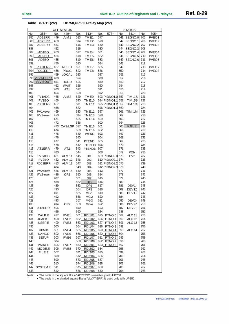
<Toc> <Ref. 8.1: Outline of Registers and I - relays> Ref. 8-29
IM 05J01B02-01E 5th Edition : Mar.25,2005-00
Table 8-1-11 (2/2) UP750,UP550 I-relay Map (2/2)
No. 385~ No. 449~ No. 513~ No. 577~ No. 641~ No. 705~385 AD1ERR 449 A/M1 513 TM E1 577 641 SEGNO.0 705 PVEO1386 AD2ERR 450 514 TM E2 578 642 SEGNO.1 706 PVEO2387 AD3ERR 451 515 TM E3 579 643 SEGNO.2 707 PVEO3388 452 516 580 644 SEGNO.3 708389 AD1BO 453 517 TM E4 581 645 SEGNO.4 709 PVEO4390 AD2BO 454 518 TM E5 582 646 SEGNO.5 710 PVEO5391 AD3BO 455 519 TM E6 583 647 SEGNO.6 711 PVEO6392 456 520 584 648 712393 RJC1ERR 457 RESET 521 TM E7 585 649 713 PVEO7394 458 PROG 522 TM E8 586 650 714 PVEO8395 459 LOCAL 523 587 651 715396 460 524 588 652 716397 461 HOL D 525 589 653 717398 462 WAIT 526 590 654 718399 463 AT1 527 591 655 719400 464 528 592 656 720401 PV1ADC 465 A/M2 529 TM E9 593 PIDNO1.0 657 TIM .1S 721402 PV1BO 466 530 TM E10 594 PIDNO1.1 658 TIM .5S 722403 RJC1ERR 467 531 TM E11 595 PIDNO1.2 659 TI M.10S 723404 468 532 596 PIDNO1.3 660 724405 PV1+over 469 533 TM E12 597 661 TIM .1M 725406 PV1-over 470 534 TM E13 598 662 726407 471 535 TM E14 599 663 727408 472 536 600 664 728409 473 CAS/LSP 537 TM E15 601 665 729410 474 538 TM E16 602 666 730411 475 539 603 667 731412 476 540 604 668 732413 477 541 PTEND
WEND
PTEND3PTEND5
605 669 733414 478 542 606 670 734415 AT1ERR 479 AT2 543 607 671 735416 480 544 608 672 PON 736417 PV2ADC 481 ALM 11 545 DI1 609 PIDNO2.0 673 PV2 737418 PV2BO 482 ALM 12 546 DI2 610 PIDNO2.1 674 738419 RJC2ERR 483 ALM 13 547 DI3 611 PIDNO2.2 675 739420 484 548 DI4 612 PIDNO2.3 676 740421 PV2+over 485 ALM 14 549 DI5 613 677 741422 PV2-over 486 OR1 550 DI6 614 678 742423 487 551 DI7 615 679 743424 488 552 DI8 616 680 744425 489 553 DP1 617 681 DEV1- 745426 490 554 DP2 618 682 DEV1Z 746427 491 555 MG1 619 683 DEV1+ 747428 492 556 MG2 620 684 748429 493 557 MG3 621 685 DEV2- 749430 494 OR2 558 MG4 622 686 DEV2Z 750431 AT2ERR 495 559 623 687 DEV2+ 751432 496 560 624 688 752433 CALB.E 497 PVE1 561 RDI101 625 PTNO.0 689 ALO 11 753434 UCALB .E 498 PVE2 562 RDI102 626 PTNO.1 690 ALO 12 754435 USER.E 499 PVE3 563 RDI103 627 PTNO.2 691 ALO 13 755436 500 564 RDI104 628 PTNO.3 692 756437 UPMD 501 PVE4 565 RDI105 629 PTNO.4 693 ALO 14 757438 RANGE 502 PVE5 566 RDI106 630 PTNO.5 694 758439 SETUP 503 PVE6 567 RDI107 631 PTNO.6 695 759440 504 568 RDI108 632 PTNO.7 696 760441 PARA.E 505 PVE7 569 RDI201 633 PTNO.8 697 761442 MODE.E 506 PVE8 570 RDI202 634 698 762443 FILE.E 507 571 RDI203 635 699 763444 508 572 RDI204 636 700 764445 509 573 RDI205 637 701 765446 510 574 RDI206 638 702 766447 SYSTEM.E 511 575 RDI207 639 703 767448 512 576 RDI208 640 704 768
RJC2ERR
VLVAT.ERRVLV.BOUT
OFF STATUS STATUS
V.GUE
Note: • The code in the square like a “AD2ERR” is used only with UP750.• The code in the shaded square like a “VLVAT.ERR” is used only with UP550.

Ref. 8-30<Toc> <Ref. 8.1: Outline of Registers and I - relays>
IM 05J01B02-01E 5th Edition : Mar.25,2005-00
When the UT750,UT550, UT551 or UT520
Table 8-1-12 UT750,UT5�� I-relay classification
1 to 16
Status
Input error (same as D0001).
I-relay Classification Description
17 to 32 PV1 error (same as D0002).
33 to 48 PV2 error (same as D0018).
49 to 64 Calibration, parameter error (same as D0035).
65 to 80 Loop1 mode (same as D0008).
81 to 96 Loop2 mode (same as D0024).
97 to 112 Alarm status (same as D0011).
113 to 160 Use not permitted.
161 to 176 External contact input status (same as D0033).
177 to 192 Expanded external contact input status (same as D0034).
193 to 208
ON status
Input error.
209 to 224 PV1 error.
225 to 240 PV2 error.
241 to 256 Calibration, parameter error.
257 to 272 Loop1 mode.
273 to 288 Loop2 mode.
289 to 304 Alarm status.
305 to 352 Use not permitted.
353 to 368 External contact input status.
369 to 384 Expanded external contact input status.
Input error.
PV1 error.
PV2 error.
Calibration, parameter error.
Loop1 mode.
Loop2 mode.
Alarm status.
Use not permitted.
External contact input status.
Expanded external contact input status.
385 to 400
OFF status
Status
401 to 416
417 to 432
433 to 448
449 to 464
465 to 480
481 to 496
497 to 544
545 to 560
561 to 576
577 to 592
User area (Note4)
Actual cascade SP No. (same as D0010). (Note1)
593 to 608 Current Loop1 PID number (same as D0009). (Note1)
609 to 624 Current Loop2 PID number (same as D0025). (Note1)
625 to 656 Use not permitted.
657 to 672 Timer setting 1 sec, 5 sec, 10 sec, 1 min. (Note2)
673 to 688 PV2, LP2 deviation lamp status. (Note3)
689 to 704 Alarm output status (same as D0036).
705 to 720 Use not permitted.
721 to 2048 User write/read area.
Note1: Four-bit information using hexadecimals:0000 for 0, 0010 for 2, 0011 for 3, to 0111 for 7, and 1000 for 8. The least significant bit of fourbits corresponds to the last digit in the relay number.
Note2: The timer settings (1, 5, 10 or 60 sec.) are only applicable to I-relay.Note3: The status of the lamps on the front panel: lit when ON(1), unlit when OFF(0) .Note4: The I-relays number 769 through 2048 in the “user area” are not shown in the I-relay map, but write or read operation is possible with
the communication function.

<Toc> <Ref. 8.1: Outline of Registers and I - relays> Ref. 8-31
IM 05J01B02-01E 5th Edition : Mar.25,2005-00
Table 8-1-13 (1/2) UT750,UT55� or UT520 I-relay Map (1/2)
No. 1~ No. 64~ No. 128~ No. 193~ No. 257~ No. 321~1 AD1ERR 65 A/M1 129 193 AD1ERR 257 A/M1 3212 AD2ERR 66 R/L1 130 194 AD2ERR 258 R/L1 3223 AD3ERR 67 R/S1 131 195 AD3ERR 259 R/S1 3234 68 132 196 260 3245 AD1BO 69 CAS 133 197 AD1BO 261 CAS 3256 AD2BO 70 AUT 134 198 AD2BO 262 AUT 3267 AD3BO 71 MA N 135 199 AD3BO 263 MA N 3278 72 136 200 264 3289 RJC1ERR 73 137 201 RJC1ERR 265 32910 RJC2ERR 74 138 202 RJC2ERR 266 33011 75 139 203 267 33112 76 140 204 268 33213 77 141 205 269 33314 78 142 206 270 33415 79 AT1 143 207 271 AT1 33516 80 144 208 272 33617 PV1ADC 81 A/M2 145 209 PV1ADC 273 A/M2 33718 PV1BO 82 R/L2 146 210 PV1BO 274 R/L2 33819 RJC1ERR 83 147 211 RJC1ERR 275 33920 84 148 212 276 34021 PV1+over 85 149 213 PV1+over 277 34122 PV1-over 86 150 214 PV1-over 278 34223 87 151 215 279 34324 88 152 216 280 34425 RSP1ADC 89 153 217 RSP1ADC 281 34526 RSP1BO 90 154 218 RSP1BO 282 34627 91 155 219 283 34728 92 156 220 284 34829 C.RSP1ADC 93 157 221 C.RSP1ADC 285 34930 C.RSP1BO 94 158 222 C.RSP1BO 286 35031 AT1ERR 95 AT2 159 223 AT1ERR 287 AT2 35132 96 160 224 288 35233 PV2ADC 97 ALM 11 161 DI1 225 PV2ADC 289 ALM 11 353 DI134 PV2BO 98 ALM 12 162 DI2 226 PV2BO 290 ALM 12 354 DI235 RJC2ERR 99 ALM 13 163 DI3 227 RJC2ERR 291 ALM 13 355 DI336 100 164 DI4 228 292 356 DI437 PV2+over 101 ALM 14 165 DI5 229 PV2+over 293 ALM 14 357 DI538 PV2-over 102 OR1 166 DI6 230 PV2-over 294 OR1 358 DI639 103 167 DI7 231 295 359 DI740 104 168 DI8 232 296 360 DI841 RSP2ADC 105 ALM 21 169 DP1 233 RSP2ADC 297 ALM 21 361 DP142 RSP2BO 106 ALM 22 170 DP2 234 RSP2BO 298 ALM 22 362 DP243 107 ALM 23 171 MG1 235 299 ALM 23 363 MG144 108 172 MG2 236 300 364 MG245 C.RSP2ADC 109 ALM 24 173 MG3 237 C.RSP2ADC 301 ALM 24 365 MG346 C.RSP2BO 110 OR2 174 MG4 238 C.RSP2BO 302 OR2 366 MG447 AT2ERR 111 175 239 AT2ERR 303 36748 112 176 240 304 36849 CALB.E 113 177 RDI101 241 CALB.E 305 369 RDI10150 UCALB .E 114 178 RDI102 242 UCALB .E 306 370 RDI10251 USER.E 115 179 RDI103 243 USER.E 307 371 RDI10352 116 180 RDI104 244 308 372 RDI10453 UTM D 117 181 RDI105 245 UTM D 309 373 RDI10554 RANGE 118 182 RDI106 246 RANGE 310 374 RDI10655 SETUP 119 183 RDI107 247 SETUP 311 375 RDI10756 120 184 RDI108 248 312 376 RDI10857 PARA.E 121 185 RDI201 249 PARA.E 313 377 RDI20158 MODE.E 122 186 RDI202 250 MODE.E 314 378 RDI20259 123 187 RDI203 251 315 379 RDI20360 124 188 RDI204 252 316 380 RDI20461 EEP.E 125 189 RDI205 253 EEP.E 317 381 RDI20562 126 190 RDI206 254 318 382 RDI20663 SYSTEM.E 127 191 RDI207 255 SYSTEM.E 319 383 RDI20764 128 192 RDI208 256 320 384 RDI208
VLVAT.ERRVLV.BOUT
VLVAT.ERRVLV.BOUT
STATUS ON STATUS
Note: • The code in the square like a “AD2ERR” is used only with UT750.• The code in the shaded square like a “VLVAT.ERR” is used only withUT550, UT551 or UT520.• Other codes are common to UT750, UT550, UT551 and UT520.

Ref. 8-32<Toc> <Ref. 8.1: Outline of Registers and I - relays>
IM 05J01B02-01E 5th Edition : Mar.25,2005-00
Table 8-1-13 (2/2) UT750,UT55� or UT520 I-relay Map (2/2)
No. 385~ No. 449~ No. 513~ No. 577~ No. 641~ No. 705~385 AD1ERR 449 A/M1 513 577 CSPNO.0 641 705386 AD2ERR 450 R/L1 514 578 CSPNO.1 642 706387 AD3ERR 451 R/S1 515 579 CSPNO.2 643 707388 452 516 580 CSPNO.3 644 708389 AD1BO 453 CAS 517 581 645 709390 AD2BO 454 AUT 518 582 646 710391 AD3BO 455 MA N 519 583 647 711392 456 520 584 648 712393 RJC1ERR 457 521 585 649 713394 RJC2ERR 458 522 586 650 714395 459 523 587 651 715396 460 524 588 652 716397 461 525 589 653 717398 462 526 590 654 718399 463 AT1 527 591 655 719400 464 528 592 656 720401 PV1ADC 465 A/M2 529 593 PIDNO1.0 657 TIM .1S 721402 PV1BO 466 R/L2 530 594 PIDNO1.1 658 TIM .5S 722403 RJC1ERR 467 531 595 PIDNO1.2 659 TIM.10S723404 468 532 596 PIDNO1.3 660 724405 PV1+over 469 533 597 661 TIM .1M 725406 PV1-over 470 534 598 662 726407 471 535 599 663 727408 472 536 600 664 728409 RSP1ADC 473 537 601 665 729410 RSP1BO 474 538 602 666 730411 475 539 603 667 731412 476 540 604 668 732413 C.RSP1ADC 477 541 605 669 733414 C.RSP1BO 478 542 606 670 734415 AT1ERR 479 AT2 543 607 671 735416 480 544 608 672 PON 736417 PV2ADC 481 ALM 11 545 DI1 609 PIDNO2.0 673 PV2 737418 PV2BO 482 ALM 12 546 DI2 610 PIDNO2.1 674 LP2 738419 RJC2ERR 483 ALM 13 547 DI3 611 PIDNO2.2 675 739420 484 548 DI4 612 PIDNO2.3 676 740421 PV2+over 485 ALM 14 549 DI5 613 677 741422 PV2-over 486 OR1 550 DI6 614 678 742423 487 551 DI7 615 679 743424 488 552 DI8 616 680 744425 RSP2ADC 489 ALM 21 553 DP1 617 681 DEV1- 745426 RSP2BO 490 ALM 22 554 DP2 618 682 DEV1Z 746427 491 ALM 23 555 MG1 619 683 DEV1+ 747428 492 556 MG2 620 684 748429 C.RSP2ADC 493 ALM 24 557 MG3 621 685 DEV2- 749430 C.RSP2BO 494 OR2 558 MG4 622 686 DEV2Z 750431 AT2ERR 495 559 623 687 DEV2+ 751432 496 560 624 688 752433 CALB.E 497 561 RDI101 625 689 ALO 11 753434 UCALB .E 498 562 RDI102 626 690 ALO 12 754435 USER.E 499 563 RDI103 627 691 ALO 13 755436 500 564 RDI104 628 692 756437 UTM D 501 565 RDI105 629 693 ALO 14 757438 RANGE 502 566 RDI106 630 694 758439 SETUP 503 567 RDI107 631 695 759440 504 568 RDI108 632 696 760441 PARA.E 505 569 RDI201 633 697 ALO 21 761442 MODE.E 506 570 RDI202 634 698 ALO 22 762443 507 571 RDI203 635 699 ALO 23 763444 508 572 RDI204 636 700 764445 EEP.E 509 573 RDI205 637 701 ALO 24 765446 510 574 RDI206 638 702 766447 SYSTEM.E 511 575 RDI207 639 703 767448 512 576 RDI208 640 704 768
V.GUE
DI1DI2DI3
DI4DI5DI6DI7DI8
VLVAT.ERRVLV.BOUT
OFF STATUS STATUS
Note: • The code in the square like a “AD2ERR” is used only with UT750.• The code in the shaded square like a “VLVAT.ERR” is used only with UT550, UT551 or UT520.• The codes DI1 to DI8 (662 to 664, 675 to 679) (reverse status) are used only with UT551.• Other codes are common to UT750, UT550, UT551 and UT520.

<Toc> <Ref. 8.1: Outline of Registers and I - relays> Ref. 8-33
IM 05J01B02-01E 5th Edition : Mar.25,2005-00
<<Ref.8.1: Outline of Registers and I - relays >>Ref.8.1(5) I-relay Timer setting
The I-relay has the timer function.The I-relay ON/OFF cycle-time can be set by the timer to 1, 5, 10seconds or 1minutes.Use the following I-relays for the timer cycle-time setting if necessary.
1sec. TIM.1S 657
5sec. TIM.5S 658
ON/OFF cycle-time I-relay code I-relay No.
10sec. TIM.10S 659
1min. TIM.1M 661
The timer function can be used when you use the “LL200 PC-based Custom Computation Building Tool”.The signal of I-relay ON/OFF status are able to output to external devices when the timer signal is registered toDO (Contact output).The I-relay ON/OFF action is shown the Fig.8-1-1 below.
Relay action
ON/OFF cycle-time
OFF(0)
ON(1)
OFF(0)
ON(1)
OFF(0)
1sec. : TIM.1S5sec. : TIM.5S10sec. : TIM.10S1min. : TIM.1M
Fig. 8-1-1 The I-relay ON/OFF Action

Blank Page

i<Int> <Toc> <Ind>
IM 05J01B02-01E 5th Edition : Mar.25,2005-00
Revision Information● Manual Title : GREEN Series Detailed Instruction
● Manual No. : IM 05J01B02-01E
1st Edition/Mar 2000Newly published.
2nd Edition/Mar 2000Error corrections.
3rd Edition/Sep 2003Error corrections.Addition of applicable models (UT351/UT321, UP351 and UM351/UM331)
4th Edition/Jul 2004Change of the company name
5th Edition/Mar 2005Addition of function
Written by Yokogawa Electric Corporation
Published by Yokogawa Electric Corporation2-9-32 Nakacho, Musashino-shi, Tokyo 180-8750, JAPAN

Blank Page


YOKOGAWA ELECTRIC CORPORATION
Network Solutions Business Division2-9-32, Nakacho, Musashino-shi, Tokyo, 180-8750 JAPANPhone: +81-422-52-7179 Facsimile: +81-422-52-6793Sales Branch OfficesTokyo, Nagoya, Osaka, Hiroshima, Fukuoka
YOKOGAWA CORPORATION OF AMERICA
Headquaters2 Dart Road, Newnan, GA. 30265-1094 U.S.A.Phone: +1-770-253-7000 Facsimile: +1-770-251-0928Sales Branch Offices / Texas, Chicago, Detroit, San Jose
YOKOGAWA EUROPE B. V.
HeadquatersDatabankweg 20, 3821 AL Amersfoort THE NETHERLANDSPhone: +31-334-64-1611 Facsimile: +31-334-64-1610Sales Branch Offices / Houten (The Netherlands), Wien (Austria), Zaventem(Belgium), Ratingen (Germany), Madrid (Spain), Bratislava (Slovakia), Runcorn (UnitedKingdom), Milano (Italy), Velizy villacoublay(France), Johannesburg(Republic of SouthAfrica)
YOKOGAWA AMERICA DO SUL S.A.
Headquarters & PlantPraca Acapulco, 31-Santo Amaro, Sao Paulo/SP, BRAZIL CEP-04675-190Phone: +55-11-5681-2400 Facsimile: +55-11-5681-4434
YOKOGAWA ENGINEERING ASIA PTE. LTD.
Head office5 Bedok South Road, Singapore 469270 SINGAPOREPhone: +65-6241-9933 Facsimile: +65-6241-2606
YOKOGAWA ELECTRIC KOREA CO., LTD.
Seoul Sales office395-70, Shindaebang-dong, Dongjak-gu, Seoul,156-010, KOREAPhone: +82-2-3284-3000 Facsimile: +82-2-3284-3019
YOKOGAWA TAIWAN CORPORATION
Head office17F, No.39, Sec. 1, Chung Hwa Road Taipei, 100 TAIWANPhone: +886-2-2314-9166 Facsimile: +886-2-2314-9918
YOKOGAWA AUSTRALIA PTY. LTD.
Head officeCentrecourt D1, 25-27 Paul Street North, North Ryde, N. S. W. 2113, AUSTRALIAPhone: +61-2-9805-0699 Facsimile: +61-2-9888-1844
YOKOGAWA INDIA LTD.
Head office40/4 Lavelle Road, Bangalore, 560 001, INDIAPhone: +91-80-227-1513 Facsimile: +91-80-227-4270
LTD. YOKOGAWA ELECTRIC
Grokholskiy per. 13, Build. 2, 4th Floor, 129010, Moscow, RUSSIA FEDERATIONPhone: +7-095-737-7868 Facsimile: +7-095-737-7869