Embed Size (px)
Citation preview

SC12205-K10-15002 1st
1
Copyright 2015, SIGMAKOKI Co.,Ltd.
User’s Manual
Three-axis Stage Controller
HSC-103

SC12205-K10-15002 1st
2
Copyright 2015, SIGMAKOKI Co.,Ltd.
Notes regarding these materials
・ These materials are intended as a reference to assist our customers in the use of
the SIGMAKOKI CO., LTD. Product best suited to the customer’s application; they
do not convey any license under any intellectual property rights, or any other rights,
belonging to SIGMAKOKI CO., LTD. or a third party.
・ SIGMAKOKI CO., LTD. assumes no responsibility for any damage, or infringement
of any third-party’s rights, originating in the use of any product data, diagram, charts,
programs, or algorithms contained in these materials.
・ All information contained in these materials, including product data, diagrams,
charts, programs and algorithms represents information on products at the time of
publication of these materials, and are subject to change by SIGMAKOKI CO.,LTD.
without notice due to product improvements or other reasons.
・ When using any or all of the information contained in these materials, including
product data, diagrams, charts, programs, and algorithm, please be sure to evaluate
all information and products. SIGMAKOKI CO., LTD. assumes no responsibility for
any damage, liability or other loss resulting from the information contained herein.
・ SIGMAKOKI CO., LTD. products are not designed or manufactured for use in
equipment or system that is used under circumstances in which human life is
potentially at stake. SIGMAKOKI CO., LTD. products cannot be used for any
specific purposes, such as apparatus or systems for transportation, vehicular,
medical, aerospace, nuclear, or undersea repeater use.
・ The prior written approval of SIGMAKOKI CO., LTD. is necessary to reprint or
reproduce in whole or in part these materials.
・ If these products or technologies are subject to the Japanese export control
restrictions, they must be exported under a license Japanese government and
cannot be imported into a country other than the approved destination.
Any diversion or re-export contrary to the export control laws and regulations of
Japan and/ or the country of destination is prohibited.

SC12205-K10-15002 1st
3
Copyright 2015, SIGMAKOKI Co.,Ltd.
Contents
For Your Safety ................................................................................................................... 4
Chapter 1: Before You Begin .............................................................................................. 6
1-1.Package Contents .............................. ....................................................................... 6
1-2. Overview ..................................... .............................................................................. 6
1-3.The HSC-103 System ............................ .................................................................... 6
1-4. Parts and Functions .......................... ....................................................................... 7
Chapter 2: Basic Operations ............................................................................................... 9
2-1.HSC-103 Connection procedure .................. ............................................................ 9
2-2. Connecting to PC and peripheral device ....... ........................................................ 9
2-3. Connecting Power Cable ....................... ................................................................ 10
2-4.USB Driver installation Method ................ ............................................................. 10
Chapter 3: Settings ........................................................................................................... 11
3-1.Memory Switch settings ........................ ................................................................. 11
3-2. Memory Switch contents list and detailed setti ngs ............................................ 11
Chapter 4: Using HSC-103 to position Motorized Stages ............................................... 22
4-1. Feature ...................................... .............................................................................. 22
4-2.Command ....................................... ......................................................................... 22
4-3. Program functions ............................ ..................................................................... 37
4-4 About the use of peripheral equipment ......... ....................................................... 40
Chapter 5: Rotation Stage ................................................................................................ 41
5-1 Setting item .................................. ........................................................................... 41
5-2 Command/ Status ............................... .................................................................... 41
5-3 Speed ......................................... .............................................................................. 41
Chapter 6: RUN current setting ....................................................................................... 42
6-1. Setting the drive current. ................... .................................................................... 42
Chapter 7: Specifications .................................................................................................. 43
7-1.Specifications ................................ .......................................................................... 43
7-2 Connector Pin Assignments ..................... ............................................................. 44
7-3. Outlines ..................................... .............................................................................. 46

4
For Your Safety Before using this product, read this manual and all warnings or cautions in the documentation provided.
Only Factory Authorized Personnel should be changes and/or adjust the parts of controller.
The Symbols Used in This Manual
! WARNING ! CAUTION
This symbol marks warnings that should be read
and used to prevent serious injury or death.
This symbol indicates where caution should be used
to avoid possible injury to yourself or others, or
damage to property.
The above indications are used together with the following symbols to indicate the exact nature of the warning or
caution.
Examples of Symbols Accompanying Warnings and Cautions
Symbols enclosed in a triangle indicate warnings and cautions. The exact nature of
the warning or caution is indicated by the symbol inside (the symbol at left indicates
risk of electrocution).
Symbols enclosed in a circle mark indicate prohibitions(actions that must not be
performed).The exact nature of the prohibition is indicates by the symbol inside or
next to the circle mark (the symbol at left indicates that the product must not be
disassembled).
Symbols inside a black circle mark actions that must be performed to ensure safety.
The exact nature of the action that must be performed is indicated by the symbol
inside (the symbol at left is used in cases in which the AC adapter must be unplugged
to ensure safety).
Symbols on the product The symbol mark on the product calls your attention. Please refer to the manual, in the case that you
operate the part of the symbol mark on the product.
! This symbol labeled on the portion calls your attention.

SC12205-K10-15002 1st
5
Copyright 2015, SIGMAKOKI Co.,Ltd.
Disclaimer of Liability
① SIGMAKOKI CO., LTD. does not accept liability for damages resulting from the use of this product or
the inability to use this product.
② SIGMAKOKI CO., LTD. does not accept liability for damages resulting from the use of this product
that deviates from that described in the manual.
③ SIGMAKOKI CO., LTD. does not accept liability for damages resulting from the use of this product in
extraordinary conditions, including fire, earthquakes, and other acts of God, action by any third party,
other accidents, and deliberate or accidental misuse.
④ If the equipment is used in a manner not specified by the SIGMAKOKI CO., LTD., the protection
provided by the equipment may be impaired.
WARNING Do not use this product in the presence of flammable gas, explosives, or corrosive substances, in areas
exposed to high levels of moisture or humidity, in poorly ventilated areas, or near flammable materials.
Do not connect or check the product while the power is on.
Installation and connection should be performed only by a qualified technician.
Do not bend, pull, damage, or modify the power or connecting cables.
Do not touch the products internal parts.
Connect the earth terminal to ground.
Should the product overheat, or should you notice an unusual smell, heat, or unusual noises coming from
the product, turn off the power immediately.
Do not turn on the power in the event that it has received a strong physical shock as the result of a fall or
other accident.
Do not touch the stage while operation.
Use dry clothes only for cleaning the equipment.
!

SC12205-K10-15002 1st
6
Copyright 2015, SIGMAKOKI Co.,Ltd.
Chapter 1: Before You Begin
1-1.Package Contents Purchasers of the Stage Controller should find that the package contains the items listed below. Check
the package contents using the following checklist. Contact your retailer as soon as possible in the event
that you should find that any item is missing or damaged.
HSC-103 Stage Controller :1
User’s Manual (This Manual) :1
AC Power Cable :1
About the setting of the Memory Switch of this controller, you can set it by sample software.
You can download sample programs from our web page.
For the details of the samples, see the manual of each program.
View our home page http://www.global-optosigma.com/en_jp/software/samp le_en.html
1-2. Overview This controller is three axes stage controller, which has drivers for five-phase stepping motor.
Because this controller has a microstep driver built-in, the smooth movement in high resolving power
is possible.
When the HST-103 is connected to an ordinary personal computer via an USB interface, the stage
can be accurately moved to the desired position by simple commands sent from the PC.
In addition, manual operation is possible facility by connecting JOYSTICK (an optional product).
1-3.The HSC-103 System
3 Axis Stage Controller
HSC-103
USB cable Control
from PC
MDR cable
MDR14-CA JS-300/JB-400/JD-100
Exe) HST-50X /HST-100X /HST-200X /HST-120YAW/HST-160YAW
D15D15A cable
D15D15A-CA
External I/O control Please interface with 10120-3000PE by
Sumitomo 3M Limited.

SC12205-K10-15002 1st
7
Copyright 2015, SIGMAKOKI Co.,Ltd.
1-4. Parts and Functions HSC-103 Front Panel
HSC-103 Rear Panel
Functions:
① POWER switch :The product is on when the switch is set to ON. Set the switch to
OFF to turn the product off.
② POWER LED :Lights up when powered.
③ Stage driving connector :Connect to the motorized stage of your choice. Supports up to
three axes.
④ USB connector :This connector is used when the device is controlled from the
computer via an USBinterface.
⑤ OPTION Connector :When control by JS-300/ JB-400 or JD-100.
※)About the usage of OPTION(JS-300/JB-400/JD-100), confirm various
User’s manual
⑥I/Oconnector ⑤OPTIONconnector ④USBconnector
⑦ACconnector ③Stage driving connector 1~3
① POWER switch ②POWER LED

SC12205-K10-15002 1st
8
Copyright 2015, SIGMAKOKI Co.,Ltd.
⑥ I/O Connector :The connector accepts a cable for sending and receiving I/O and
control signals to form an external device. and it can connect an
input and output signal and a stop signal to external equipment.
⑦ AC connector :This is where you connect the supplied 2.3meter power cable.
USABLE DETACHABLE POWER CORDS
Type Connecter Cord Attachment plug cap
AC100-120V Use the detachable power cord set attached to the product only.
AC200-240V IEC C-22
Rated 7A, 250V
UL, CSA Approved
Type SJT, No16 AWG Min.
3-Conductors
(Single phased;2-current carrying &
ground)
UL, CSA Approved
NEMA6-15P
Tandem blade
Rated 7A,250V
UL, CSA Approved
Cable length of above Power Supply cord shall be shorter than 4.5m.
For your own safety, make sure POWER is OFF before connecting every cable.
SC12205-K10-15002 1st
9
Copyright 2015, SIGMAKOKI Co.,Ltd.
Chapter 2: Basic Operations
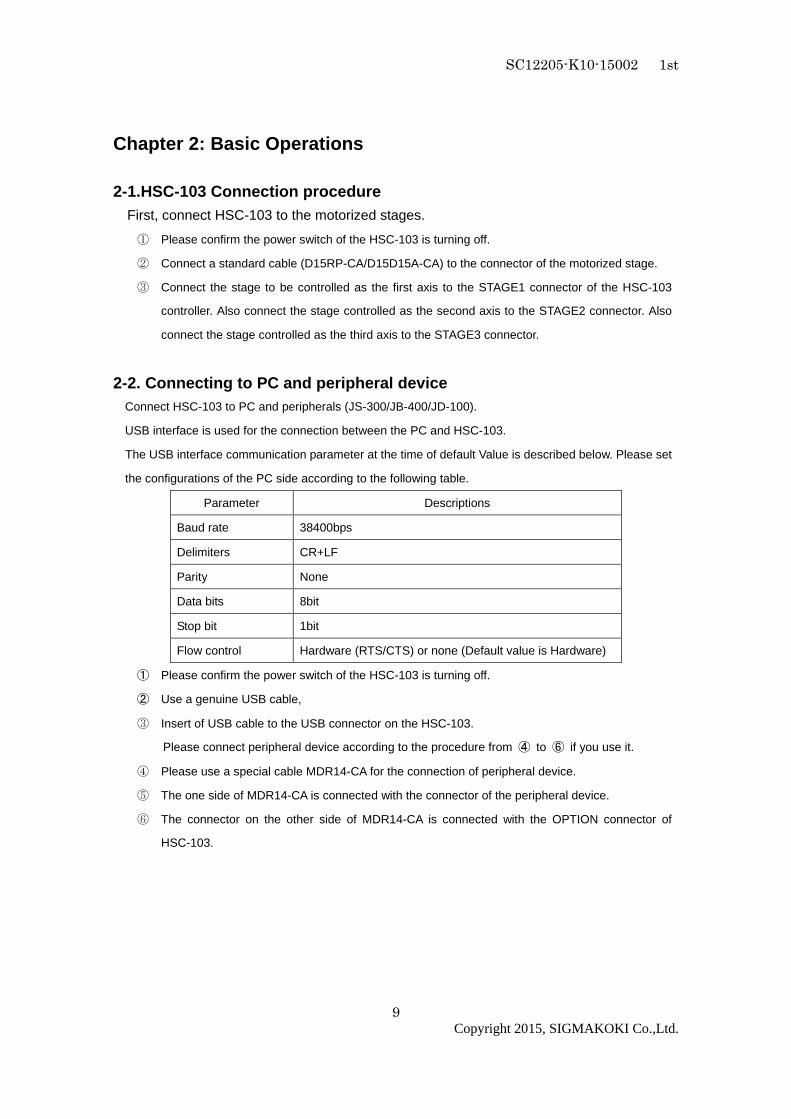
2-1.HSC-103 Connection procedure First, connect HSC-103 to the motorized stages.
① Please confirm the power switch of the HSC-103 is turning off.
② Connect a standard cable (D15RP-CA/D15D15A-CA) to the connector of the motorized stage.
③ Connect the stage to be controlled as the first axis to the STAGE1 connector of the HSC-103
controller. Also connect the stage controlled as the second axis to the STAGE2 connector. Also
connect the stage controlled as the third axis to the STAGE3 connector.
2-2. Connecting to PC and peripheral device Connect HSC-103 to PC and peripherals (JS-300/JB-400/JD-100).
USB interface is used for the connection between the PC and HSC-103.
The USB interface communication parameter at the time of default Value is described below. Please set
the configurations of the PC side according to the following table.
Parameter Descriptions
Baud rate 38400bps
Delimiters CR+LF
Parity None
Data bits 8bit
Stop bit 1bit
Flow control Hardware (RTS/CTS) or none (Default value is Hardware)
① Please confirm the power switch of the HSC-103 is turning off.
② Use a genuine USB cable,
③ Insert of USB cable to the USB connector on the HSC-103.
Please connect peripheral device according to the procedure from ④ to ⑥ if you use it.
④ Please use a special cable MDR14-CA for the connection of peripheral device.
⑤ The one side of MDR14-CA is connected with the connector of the peripheral device.
⑥ The connector on the other side of MDR14-CA is connected with the OPTION connector of
HSC-103.

SC12205-K10-15002 1st
10
Copyright 2015, SIGMAKOKI Co.,Ltd.
2-3. Connecting Power Cable Connect the supplied power cable to the AC connector on the rear panel of HSC-103 to plug the cable
into an outlet. (Ensure that it is grounded.)
2-4.USB Driver installation Method please use after the installation of the USB-driver in the following content.
(In the case of Windows 7/ Windows 8/ Windows 8.1)
While the Internet is connected, when connected toHSC-103, the installation of an automatic driver will
start.
*) If unconnected to the Internet, from FTDI’s web site on a PC connected to the Internet, please go
to download the driver (VCP Drivers). Then move the driver that download to PC to connect the
HSC-103. Please then perform the installation of th e driver.
The FTDI website ( http://www.ftdichip.com/index.html )

SC12205-K10-15002 1st
11
Copyright 2015, SIGMAKOKI Co.,Ltd.
Chapter 3: Settings
3-1.Memory Switch settings The Memory Switches store the controller settings.
When changing Memory Switch settings use the Sample software (SGSample), which can be
downloaded from http://www.global-optosigma.com/en_jp/software/samp le_en.html
*) After changing Memory Switch, be sure to reboot the power HSC-103.
3-2. Memory Switch contents list and detailed setti ngs 3-2-1 General
No Memory Switch contents Setting Range / Select items Default Value
1 SPD SEL 1~4 1
2 SPD 1 S 1~999999999 10000
3 SPD 1 F 1~999999999 100000
4 SPD 1 R 1~1000 200
5 SPD 2 S 1~999999999 30000
6 SPD 2 F 1~999999999 300000
7 SPD 2 R 1~1000 200
8 SPD 3 S 1~999999999 70000
9 SPD 3 F 1~999999999 700000
10 SPD 3 R 1~1000 200
11 SPD 4 S 1~999999999 100000
12 SPD 4 F 1~999999999 1000000
13 SPD 4 R 1~1000 200
14 IO_LVL ACT HIGH/ACT LOW ACT HIGH
1) SPD SEL:Speed selection at Power ON
Select the initial setting Speed No. at Power ON.
[Setting Range] 1 ~ 4
2)~13) Speed 1~4(S)(F)(R):Speed Setting
Set 4 kinds of travel stage Speed (minimum S, maximum F, and acceleration/deceleration time R) at
Power ON. When JS-300(Option) operation and during the internal program behavior, work in this
movement speed setting.
[Setting Range] S:1~999999999 (Unit:0.01µm/s)
F:1~999999999 (Unit:0.01µm/s)
R:1~1000 (Unit:ms)
*) Minimum S values should be set smaller than maxi mum F at Speed Setting.

SC12205-K10-15002 1st
12
Copyright 2015, SIGMAKOKI Co.,Ltd.
14) IO_LVL:I/O Output signal logic Setting
Select Logic (Voltage level) for I/O output signal.
[Select item] ACT HIGH:Lo level (Active High) normally
ACT LOW:Hi level (Active low) normally
3-2-2 INTERFACE
No Memory Switch contents Setting Range / Select items Default Value
1 BAUDRATE 9600/38400/57600 38400
1) BAUDRATE:Baudrate setting
Set the data communication speed for the USB (Serial communication) Interface.
[Select item] 9600:9600bps
38400:38400bps
57600:57600bps
3-2-3 Axis
No Memory Switch contents Setting Range / Select items Default Value
1 STG UT1 PULSE/MICRO/DEGREE MICRO
2 STG UT2 PULSE/MICRO/DEGREE MICRO
3 STG UT3 PULSE/MICRO/DEGREE MICRO
4 PLS_RATE1 1~1000000 1000
5 PLS_RATE2 1~1000000 1000
6 PLS_RATE3 1~1000000 1000
7 MOVE1 POS/NEG POS
8 MOVE2 POS/NEG POS
9 MOVE3 POS/NEG POS
10 ORG1 SEL OFF/MINI/CENTER/ORGS/NORM/ZPM/ZPP MINI
11 ORG2 SEL OFF/MINI/CENTER/ORGS/NORM/ZPM/ZPP MINI
12 ORG3 SEL OFF/MINI/CENTER/ORGS/NORM/ZPM/ZPP MINI
13 ORG OFFSET1 0~999999999 0
14 ORG OFFSET2 0~999999999 0
15 ORG OFFSET3 0~999999999 0
16 CONFIG1 ON/OFF ON
17 CONFIG2 ON/OFF ON
18 CONFIG3 ON/OFF ON

SC12205-K10-15002 1st
13
Copyright 2015, SIGMAKOKI Co.,Ltd.
1~3) STG_UT1~3:Select the units for display
Set the units used to display position coordinates of OPTION_unit (JS-300, JB-400).
[Select item] PULSE: Number of pulses
MICRO: Micron m units
DEGREE: Degrees units
4~6) PLS_RATE1~3:Pulse Rate setting(1~3axes))
Set the travel distance per 1 pulse for each axis.
The divisions of the driver set at 40. If the setting is not right, right positioning movement is not possible.
*) Otherwise, it is not able to position correctly. (Setting Unit :::: 0.1nm ) *1)
[Setting range] 1~1000000 (0.1nm~100µm) *1)
*1) If “STG_UT1~4” setting is “DEGREE”, please sett ing Unit: 0.000001°.
7~9) MOVE1~3:Travel direction setting 1~3axis
Set + travel direction for each axis.
[Select item] POS: Positive rotation
NEG: Negative rotation
10~12) ORG1 SEL~ORG3 SEL:Origin reset method setting
Set Origin reset method for each axis.
[Select item] OFF: Origin reset OFF (ORG0)
MINI: ORG1
CENTER: ORG2
ORGS: ORG3
NORM: ORG4
ZPM: ORG5
ZPP: ORG6
*) Regarding each method, please refer to “Origin Reset Method”.
13~15) ORG OFFSET1~3:ORG offset setting
Set ORG offset value for each axis (ORG1、ORG5、ORG6) at the ORG reset.
[Setting range] 0~999999999 (Unit:0.01µm)
*) When Setting range is set [0], ORG offset value is 0.5mm.

SC12205-K10-15002 1st
14
Copyright 2015, SIGMAKOKI Co.,Ltd.
16~18) CONFIG1~3:Select Auto-Config mode.
Set Auto-Config mode for each axis.
[Select item] ON:effect
OFF:no effect

SC12205-K10-15002 1st
15
Copyright 2015, SIGMAKOKI Co.,Ltd.
『『『『Origin Reset Method 』』』』 There are six types in Origin Reset setting. Please select optimal Origin Reset setting for stage in use
depending upon software.
There are two parameters to do with Origin Reset, which are Origin Reset Speed (S, F, R, M) and Origin
offset (ORG OFFSET). Parameters of each axis can be individually set. Please select the optimum value
according to the software.
In case of when PGO (Z pulse) is used as an Origin sensor, (ORG5 or ORG6), Origin sensor is not in need
at stage since Excitation Reset of motor driver is used.
1, ORG0 Not reset ORGIN position.
2, ORG1 (MINI method compatible, however stage moves to ORG offset value)
ORG OFFSET default value: 0.5mm.
CW(CCW) Sensor
Detect CW limit sensor
Move 0.5mm
Detect CW limit sensor
Move to offset position
ORG reset speed M
ORG reset speed S
ORG reset speed M
ORG reset speed F

SC12205-K10-15002 1st
16
Copyright 2015, SIGMAKOKI Co.,Ltd.
3, ORG2 (CENTER method)
4, ORG3 (for 3 sensor use (LS + ORG))
4-1) In case that ORG sensor is set on the inside of CW(CCW) sensor
CCW(CW) Sensor CW (CCW) Sensor
ORG reset speed F Detect CW limit sensor
ORG reset speed F
Move 0.5mm
ORG reset speed M
Detect CW limit sensor
ORG reset speed M
Detect CCW limit sensor
ORG reset speed M
ORG reset speed S
Move 0.5mm
ORG reset speed S Detect CCW limit sensor
LS halfway point
Move to halfway point
between CW/CCW sensor
ORG reset speed F
ORG sensor CW (CCW) Sensor
Detect ORG sensor
Move 0.5mm
Detect ORG sensor
ORG reset speed M
ORG reset speed S

SC12205-K10-15002 1st
17
Copyright 2015, SIGMAKOKI Co.,Ltd.
4-2) In case that ORG sensor is set beyond limit SW toward CW direction.
Caution1) In case that after detect CW (CCW) sensor, stage move toward CCW direction and then can not
detect ORG sensor (in case of no ORG sensor), stage stop at CCW (CW) sensor position.
5, ORG4 (for 4 sensor (LS+SD+ORG) use.)
5-1) In case that NEAR ORG sensor is on the inside of CW(CCW) sensor.
Detect ORG sensor
ORG sensor
ORG reset speed F
Detect CW limit sensor
Move 0.5mm
CW (CCW) sensor
ORG reset speed M
ORG reset speed S
ORG reset speed M
Detect ORG sensor
NEAR ORG sensor
ORG reset speed F Detect NEAR ORG sensor
Detect ORG sensor
ORG sensor
ORG reset speed S
CW (CCW) sensor

SC12205-K10-15002 1st
18
Copyright 2015, SIGMAKOKI Co.,Ltd.
5-2) In case that ORG sensor is beyond NEAR ORG sensor toward CW(CCW) direction.
Caution1) In case that after detect CW (CCW) sensor, stage move toward CCW direction and then can not
detect NEAR ORG sensor (in case of no NEAR ORG sensor), stage stop at CCW (CW) sensor
position.
Caution 2) In case that after detect NEAR ORG sensor, stage move toward CW direction and then can not
detect ORG sensor (in case of no ORG sensor), stage stop at CW (CCW) sensor position.
6, ORG5 (for 3 sensor use (LS+ORG(Z phase)))
NEAR ORG sensor ORG sensor
ORG reset speed F
Detect CW limit sensor
Detect NEAR ORG sensor
ORG reset speed S
CW (CCW) sensor
ORG reset speed M
Detect ORG sensor
ORG reset speed F
ORG sensor (Z phase) CW (CCW) sensor
Detect CW limit sensor
Move to offset position
Detect ORG sensor
(z phase)
ORG reset speed M
ORG reset speed S

SC12205-K10-15002 1st
19
Copyright 2015, SIGMAKOKI Co.,Ltd.
7, ORG6 (for 3 sensor use (LS+ORG(Z phase)))
ORG reset speed S
ORG reset speed S
ORG reset speed F
ORG sensor (Z phase) CW (CCW) sensor
Detect CW limit sensor
Move to offset position
After detect ORG sensor
move to 0.5mm position
Detect ORG sensor
(Z phase)
ORG reset speed M
SC12205-K10-15002 1st
20
Copyright 2015, SIGMAKOKI Co.,Ltd.
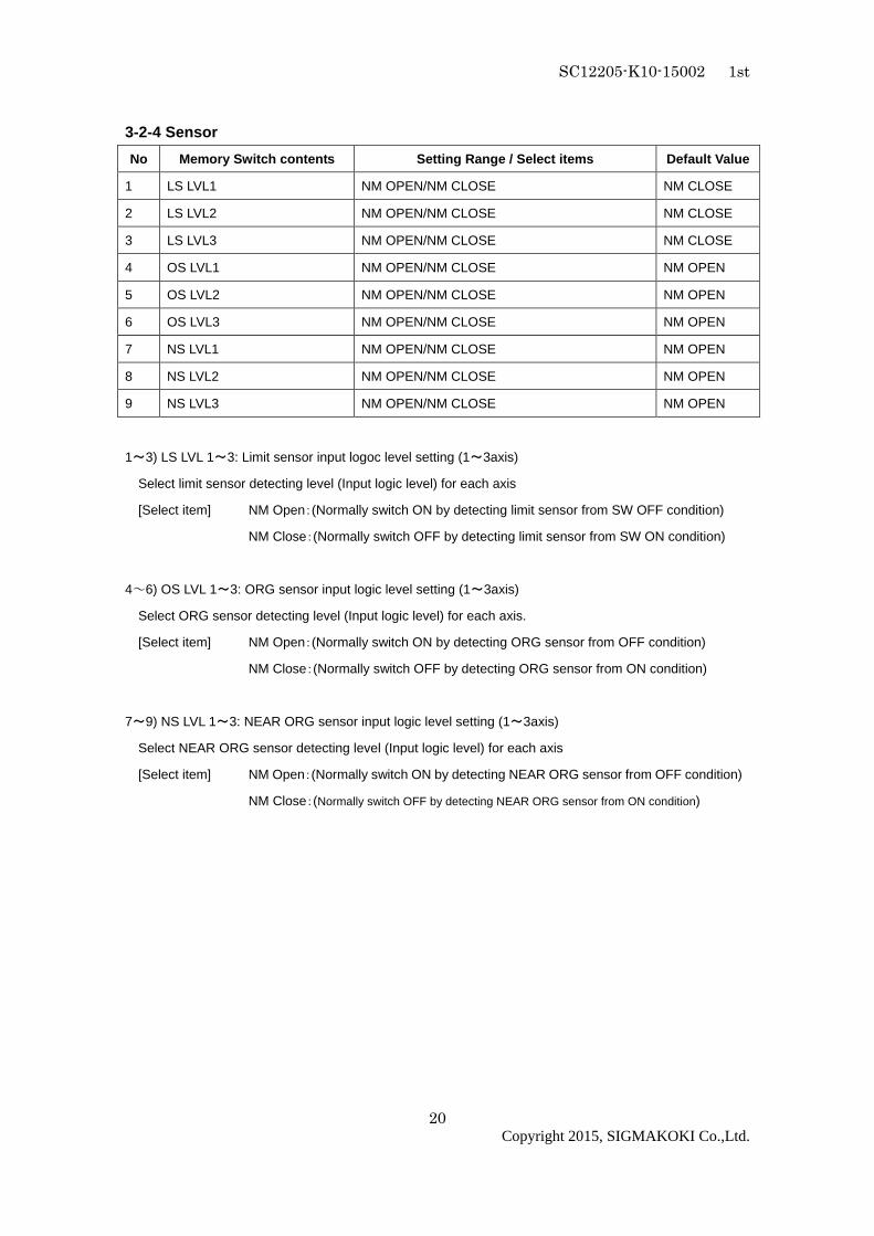
3-2-4 Sensor
No Memory Switch contents Setting Range / Select items Default Value
1 LS LVL1 NM OPEN/NM CLOSE NM CLOSE
2 LS LVL2 NM OPEN/NM CLOSE NM CLOSE
3 LS LVL3 NM OPEN/NM CLOSE NM CLOSE
4 OS LVL1 NM OPEN/NM CLOSE NM OPEN
5 OS LVL2 NM OPEN/NM CLOSE NM OPEN
6 OS LVL3 NM OPEN/NM CLOSE NM OPEN
7 NS LVL1 NM OPEN/NM CLOSE NM OPEN
8 NS LVL2 NM OPEN/NM CLOSE NM OPEN
9 NS LVL3 NM OPEN/NM CLOSE NM OPEN
1~3) LS LVL 1~3: Limit sensor input logoc level setting (1~3axis)
Select limit sensor detecting level (Input logic level) for each axis
[Select item] NM Open:(Normally switch ON by detecting limit sensor from SW OFF condition)
NM Close:(Normally switch OFF by detecting limit sensor from SW ON condition)
4~6) OS LVL 1~3: ORG sensor input logic level setting (1~3axis)
Select ORG sensor detecting level (Input logic level) for each axis.
[Select item] NM Open:(Normally switch ON by detecting ORG sensor from OFF condition)
NM Close:(Normally switch OFF by detecting ORG sensor from ON condition)
7~9) NS LVL 1~3: NEAR ORG sensor input logic level setting (1~3axis)
Select NEAR ORG sensor detecting level (Input logic level) for each axis
[Select item] NM Open:(Normally switch ON by detecting NEAR ORG sensor from OFF condition)
NM Close:(Normally switch OFF by detecting NEAR ORG sensor from ON condition)

SC12205-K10-15002 1st
21
Copyright 2015, SIGMAKOKI Co.,Ltd.
3-2-5 Speed
No Memory Switch contents Setting Range / Select items Default Value
1 ORG1 SPD S 1~999999999 50000
2 ORG1 SPD F 1~999999999 500000
3 ORG1 SPD R 1~1000 200
4 ORG2 SPD S 1~999999999 50000
5 ORG2 SPD F 1~999999999 500000
6 ORG2 SPD R 1~1000 200
7 ORG3 SPD S 1~999999999 50000
8 ORG3 SPD F 1~999999999 500000
9 ORG3 SPD R 1~1000 200
10 ORG1 SPD M 1~999999999 250000
11 ORG2 SPD M 1~999999999 250000
12 ORG3 SPD M 1~999999999 250000
1~12) ORG1~3 SPD(S)(F)(R)(M): ORG reset speed setting
Set mechanical ORG reset speed (minimum speed S, maximum speed F, acceleration time, ORG-reset
speed M) for each axis.
[Setting Range] S:1~999999999(Unit:0.01µm/s)
F:1~999999999(Unit:0.01µm/s)
R:1~1000(Unit:ms)
M:1~999999999(Unit:0.01µm/s)
*) Regarding Speed setting, minimum speed S should be set smaller than maximum speed F and
ORG-reset speed M.

SC12205-K10-15002 1st
22
Copyright 2015, SIGMAKOKI Co.,Ltd.
Chapter 4: Using HSC-103 to position Motorized Stag es
4-1. Feature The controller can be connected to a computer using an USB interface. Motorized stages can then be
precisely controlled by commands (strings) transmitted from the computer.
And command format of HSC-103, will be compatible with our controller (HIT-M/PGC).
The USB interface communication parameter at the time of default Value is described below. Please set
the configurations of the PC side according to the following table.
Parameter Descriptions
Baud rate 38400bps
Delimiters CR+LF
Parity None
Data bits 8bit
Stop bit 1bit
Flow control Hardware (RTS/CTS)
4-2.Command
4-2-1 Format of command General format is shown below. Some formats are different depending on type of command. Please
refer to each command explanation for details.
code:p1,p2,p3
code Use a string to represent a command.
: Command separation (Colon(:))
p1~p3 Use(,)command to separate and assign number of slave unit 1-3. Only integer
values can be used as parameter values.
A decimal number is an incorrect command and will be response by NG.
+ sign can be abbreviated. +1000 or 1000 is treated as the same command.
A travel or distance parameter of 1 is equal to 0.01µm.
Parameter is abbreviated when NOP (No Operation) needs to be set to the designated
slave unit number.
Note: (,)cannot be abbreviated.
((((Ex)))) ,p2 Parameter of 1 and 3-axis is abbreviated.
p1,,p3 Parameter of 2-axis is abbreviated.

SC12205-K10-15002 1st
23
Copyright 2015, SIGMAKOKI Co.,Ltd.
Capital or lower case characters can be used. Example: h and H are both valid for the Home command.
Backspace is effective to delete a prior string.
Command string must not have leading or trailing spaces. Otherwise, the command string will not be
accepted and NG will be returned as a command error.
Immediate movement will be made in case when activation commands such as H, M, A, E, K, and J
commands are accepted normally. Unlike the SHOT-Controller, the activation command (G) is not
needed in HSC-103. Activation command (G) is treated as an incorrect command In HSC-103.
When issuing Q, ?, !, or I command, its status will be responded. In case which other commands are
issued, ‘OK’ or ‘NG’ sign will be responded. ‘OK’ and ‘NG’ signs hereby mean ‘normal acceptance’ and
‘acceptance refused for an incorrect command’ respectively. When other commands except Q, ?, L, !, I,
O commands are issued to an engaged slave in busy condition, ‘NG’ sign will be responded for
incorrect commands, which will result in the whole command not being executed.
・・・・4-2-2 Command list
Command Movement Detail
H Return to mechanical origin Detect mechanical origin
M Set number of pulses for
relative movement
Setting of Axis of movement, direction, number of pulses
with relative coordinate
A Set number of pulses for
absolute movement
Setting of Axis of movement, direction, number of pulses
with absolute coordinate
E Settings of rotary movement Circular interpolation (Move at minimum speed (S))
K Settings of linear interpolation
movement
Linear interpolation (Move at minimum speed (S))
J Jog command Move by minimum speed (S)
L Stop Stop or reduce speed
R Set electronic (logical) origin Set the electronic (logical) origin to the current position
D Speed settings Set S, F, and R of M and A command
B Setting of returning origin
speed
Setting of returning origin command (S, F, R and M)
C Free motor Excitation ON/OFF
Q Status1 Return current position etc.
! Status2 Return 1(Busy) or 0 (READY)
? Internal information Return by internal information
O I/O output command Output data to OUT terminal of I/O connector
I I/O input check Return data to IN terminal of I/O connector
P Program control Internal program command

24
4-2-3 H command (Return to mechanical origin comman d) (1) Function
This command indicates detect the mechanical origin for a stage and set the position as the origin.
Coordinate value is cleared by 0.
When the designated axis number with parameter is 1, the mechanical origin will be operated. No
operation to 0 or abbreviated axis.
(2) Example
H:1,1,0 means to operate the mechanical origin to axis number 1 and 2
4-2-4 M command (Relative movement command) (1) Function
This command indicates relative movement with pulse number.
Travel is a length and indicates by (0.01µm unit)
*) Controller enables to output number of pulse (-1 34217728 to +134217727). In case of the over
number, NG will be returned and stage will not move .
(Note: The above limitation is conflicted when a hi gh microstep is set.)
(2) Example
M:100000,-20000,30000 means to move from current position 1mm, -0.2mm and 0.3mm to axis
number 1, 2 and 3 respectively.
4-2-5 A command (Absolute movement command) (1) Function
This command indicates Relative movement with pulse number.
Travel is a length and indicates by (0.01µm unit)
*) Controller enables to output number of pulse (-1 34217728 to +134217727). In case of the over
number, NG will be returned and stage will not move . Actual length of travel is calculated
automatically by controller from a specified absolu te movement length value.
(Note: The above limitation is conflicted when a hi gh microstep is set.)
(2) Example
A:0,-20000,30000 means to return to origin (0), -0.2mm and 0.3mm of absolute position to
axis number 1,2 and 3 respectively.

25
4-2-6 E command (Arc interpolation movement command ) (1) Function
This command for arc interpolation movement enables to specify operation axis and rotation direction. 3
different modes of parameter are available to operate the arc interpolation movement with arbitrary 2
axes. When this command is sent under condition of busy and unconnected of axis, it will be response
by NG as a command error and all command will stop to operate.
To operate an interpolation with this command, puls e speed and travel per pulse (PLS_RATE)
must be identical for both axes.
Otherwise, an interpolation movement will be unable to operate due to an incorrect setting.
Note: if there is a difference in PLS_RATE between a xis, apparent speed ( [S, F, R value] and
[Microstep] and [Acceleration and Deceleration] pat tern (Trapezoidal shape or S shape)) is same,
pulse speed and travel per pulse are different. How ever the speed when operates the arc
interpolation movement is minimum speed (S).
Coordinate of arc movement is specified based on the relative travel from current position (0.01µm
unit).
E::::0 command (Arc interpolation movement command 0) is a setting for the end of Coordinate. In order
to move out from a circular line as shown by the
image right hand side, the end movement of one
axis when it reaches to a specified position in a
quadrant and stop the interpolation function. Then,
another axis move to reach the end point.
Note: the specified end point as ended coordinate
of arc interpolation inside the area of diagonal line,
the stage will move non-stop and arc interpolation
movement is effective without end.
Due to operation by calculation, there is a
calculation error to the ended point of E :::: 1
command (Arc interpolation movement command 1) and E::::2command (Arc interpolation movement
command 2). Please check the actual stage.

SC12205-K10-15002 1st
26
Copyright 2015, SIGMAKOKI Co.,Ltd.
4-2-6-1 E:0 command (Arc interpolation movement command 0000) (1) Function
This command indicates a designation of ended point and center point in order to operate the arc
movement.
(2) Example
E::::0,axis1,axis2,d,e1,e2,c1,c2
Axis1, axis2 ::::1~~~~3 means to designate the number of axis to operate arc interpolation
movement. Same number of axis or unconnect is prohibited.
Axis 1 represents X axis and axis 2 represents Y axis.
d::::0 or 1 0 is CW rotation (Clockwise), 1 is CCW rotation (Counterclockwise)
e::::Ended point coordinate (e1 axi1 setting value、e2 axis2 setting value) (unit of setting 0.01µm unit)
c::::Center point coordinate (c1 axis1 setting value、c2 axis2 setting value) (unit of setting 0.01µm unit)
E::::0,1,3,0,0,0,5000,-5000 A center point coordinate is based on a relative coordinate of the current
position (0.05mm,-0.05mm) and move stages of axis No1, axis No3 one
round clockwise until the current position.
0.05mm
-0.05mm
Axis 1
Axis 3

27
4-2-6-2 E::::1 command (Arc interpolation movement command 1) (1) Function
This command indicates a designation of center point and degree of ended point in order to operate the
arc movement
(2) Example
E::::1, axis1,axis2,d,c1,c2,ae
axis1, axis2 ::::1~~~~3 means to designate the number of axis to operate arc interpolation
movement. Same number of axis or unconnect is prohibited. Axis1
represents X axis and axis2 represents Y axis.
d::::0 or 1 0 is CW rotation(Clockwise). 1 is CCW rotation (Counterclockwise).
c::::Center point coordinate (c1 axis1 setting value、c2 axis2 setting value)
(unit of setting 0.01µm unit)
ae::::Degree of ended point (deg) (Setting range:integer of 0°<ae≦360° The other degree
than mentioned is NG.)
E::::1,2,3,0,5000,-5000,90 A center point coordinate is based on a relative coordinate of the current
position (0.05mm,-0.05mm) and move stages of axis No2、axis No3
90°from current position to degree of ended point position clockwise.
0.05mm
-0.05mm 90°
Axis2
Axis 3

28
4-2-6-3 E::::2 command (Arc interpolation movement command 2) (1) Function
This command indicates a designation of pass point coordinate and ended point’s coordinate in order to
operate the arc interpolation movement. Note: if 3 points (current position, pass point coordinate and
ended point coordinate) lay on the same straight line, it is unable to make an arc movement.
(2) Example
E::::2, axis1,axis2,p1,p2,e1,e2
axis1, axis2 ::::1~~~~3 means to designate the number of axis to operate arc interpolation
movement. Same number of axis or unconnected is prohibited. Axis 1
represents X axis and axis 2 represents Y axis.
p::::Pass point coordinate (p1 axis1 setting value、p2 axis2 setting value)
(unit of setting 0.01µm unit)
e::::Ended point coordinate (e1 axis1 setting value、e2 axis2 setting value)
(unit of setting 0.01µm unit)
E::::2,1,2,5000,3000,8000,12000 Pass point coordinate and ended point coordinate are based on
a relative coordinate of the current position (+0.05mm,
+0.03mm) and (+0.08mm, +0.12mm). Then, stages of axis No1、
axis No2 move circularly.
0.05mm 0.08mm
0.03mm
0.12mm
Axis 1
Axis 2
29
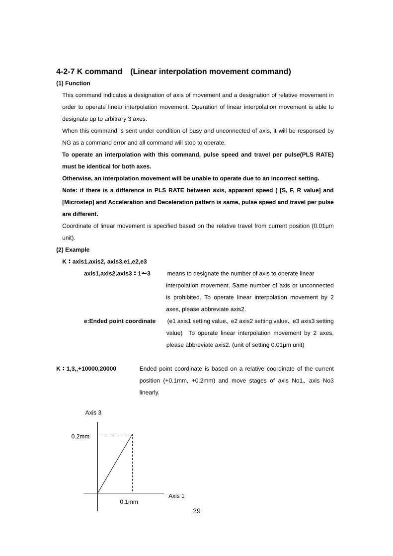
4-2-7 K command (Linear interpolation movement command) (1) Function
This command indicates a designation of axis of movement and a designation of relative movement in
order to operate linear interpolation movement. Operation of linear interpolation movement is able to
designate up to arbitrary 3 axes.
When this command is sent under condition of busy and unconnected of axis, it will be responsed by
NG as a command error and all command will stop to operate.
To operate an interpolation with this command, puls e speed and travel per pulse(PLS RATE)
must be identical for both axes.
Otherwise, an interpolation movement will be unable to operate due to an incorrect setting.
Note: if there is a difference in PLS RATE between axis, apparent speed ( [S, F, R value] and
[Microstep] and Acceleration and Deceleration patte rn is same, pulse speed and travel per pulse
are different.
Coordinate of linear movement is specified based on the relative travel from current position (0.01µm
unit).
(2) Example
K::::axis1,axis2, axis3,e1,e2,e3
axis1,axis2,axis3 ::::1~~~~3 means to designate the number of axis to operate linear
interpolation movement. Same number of axis or unconnected
is prohibited. To operate linear interpolation movement by 2
axes, please abbreviate axis2.
e:Ended point coordinate (e1 axis1 setting value、e2 axis2 setting value、e3 axis3 setting
value) To operate linear interpolation movement by 2 axes,
please abbreviate axis2. (unit of setting 0.01µm unit)
K::::1,3,,+10000,20000 Ended point coordinate is based on a relative coordinate of the current
position (+0.1mm, +0.2mm) and move stages of axis No1、axis No3
linearly.
0.2mm
0.1mm Axis 1
Axis 3

30
4-2-8 J command (Jog command) (1) Function
This command indicates to drives stages continuously (at a constant speed) at the minimum pulse
speed (S). During command operation, stage will move non-stop until the detection of limit sensor or
receipt of Stop command (L command).
(2) Example
J::::s1,s2,s3
s::::+,- or abbreviated + is + direction, - is - direction、abbreviated is NOP(No
Operation).
J::::,+,- Jog movement to axis No2 is + direction, axis No3 is - direction. No movement to
axis No1.
4-2-9 L command (Decelerate and stop command) (1) Function
Deceleration and stop stage
(2) Example
L::::p1,p2,p3
p::::0,1 or abbreviated 1 is to decelerate and stop stage of the axis number. 0 or
abbreviated are NOP(No Operation).
L::::,,1 To decelerate and stop stage of the axis No3.
4-2-10 L:E command (Emergency stop (Immediate stop) command) (1) Function
This command indicates to stop stages of all axis immediately.
(2) Example
L::::E means to stop stages of all axis immediately.

31
4-2-11 R command (Return to logical origin command) (1) Function
This command indicates a setting of logical origin (coordinate value 0) to the stage of the designated
axis number based on the current position.
When this command is sent under condition of busy and unconnected of axis, it will be responsed by
NG as a command error and all command will stop to operate.
(2) Example
R::::p1,p2,p3
p::::0,1 or abbreviated 1 is to set the logical origin to the stage of the axis number. 0 or
abbreviated are NOP(No Operation)
R::::0,1,1 means to set the logical origin (coordinate value 0) to the stage of the
axis number 2 and 3.
4-2-12 D command (Speed setting command) (1) Function
This command indicates a speed setting to the designated axis number. It is unable to set the multiple
number of axes at the same time.
When this command is sent under busy condition of axis, it will be responsed by NG as a command
error and all command will stop to operate.
(2) Example
D::::axis,s,f,r
axis :::: axis number 1~3
s:::: Start-up speed (Initial speed) range of setting: 1~999999999 (unit : 0.01µm/s)
f:::: Maximum speed range of setting: 1~999999999 (unit : 0.01µm/s)
r:::: Acceleration / deceleration time range of setting:1~1000 (unit : ms)
Note : the condition of s<=f
*) Maximum speed (calculated by pulse) is 4000000(pulse/s). In case of over speed setting (travel:
0.01µm/s unit), OK will be returned, but it will be treated as speed of 4000000(pulse/s).
D::::3,20000,200000,200 means Start-up speed : 0.2mm/s, 2mm/s : Maximum speed, 200ms :
Acceleration / deceleration time to axis No3.

SC12205-K10-15002 1st
32
Copyright 2015, SIGMAKOKI Co.,Ltd.
4-2-13 B command (Setting of returning origin speed command) (1) Function
This command indicates the setting of returning origin speed to the designated axis number. It is unable
to set the multiple number of axis at the same time. When this command is sent under condition of busy
and unconnected of axis, it will be responsed by NG as a command error and all command will stop to
operate. When the power is turned on, it will be the setting speed of the memory switch.
(2) Example
B::::axis,s,f,r,m
axis:::: axis No.1~3
s:::: Start-up speed (Initial speed) range of setting: 1-999999999 (unit : 0.01µm/s)
f:::: Maximum speed range of setting: 1-999999999 (unit : 0.01µm/s)
r:::: Acceleration/deceleration time range of setting:1-1000 (unit : ms)
m:::: ORG reset speed range of setting: 1-999999999 (unit : 0.01µm/s)
Note : the condition of s ≦≦≦≦m≦≦≦≦f
*) Maximum speed (calculated by pulse) is 4000000(pulse/s). In case of over speed setting (travel:
0.01µm/s unit), OK will be returned, but it will be treated as speed of 4000000(pulse/s).
B:3,10000,200000,200,100000 Setting start-up speed by 0.1mm/s, Maximum speed by 2mm/s,
Acceleration/deceleration time by 200m and ORG reset speed
by 1mm/s to axis No3.
4-2-14 C command (Excitation On/OFF command) (1) Function
This command indicates an Excitation On/OFF of motor. The stage is able to move (rotate) manually
when the excitation OFF of motor.
When this command is sent under busy condition of slave unit, it will be responsed by NG as a
command error and all command will stop to operate.
(2) Example
C::::p1,p2,p3
p::::0,1 or abbreviated 1 is an Excitation ON to the stage of the axis number. 0 is an
Excitation OFF to the stage of the axis number. The
abbreviation is NOP(No Operation)
C::::0,0,1 Excitation ON to the motor of the axis No3, and OFF to motor of axis No1,2.

33
4-2-15 Q command (Reading current position command) (1) Function
This command indicates to return the current position information of 3 tages of axis.unit No 1-3(0.01µm
unit). In the case of pulse specified in memory SW, return the number of pulses. The returned current
position data is separated by (,) -mark represents when the current position is minus. Maximum 10 digit
including marking by left-align display. Driver Alarm because the coordinate values when the on is
undetermined comma (,) only will be returned.
(2) Example
Q::::
-1000,1000,0 Return data : current position of axis No1 is -0.01mm, 0.01mm
to axis No2, and 0mm to axis No3.
4-2-16 Q:S command (Reading status command) (1) Function
This command indicates to return the status information of controller and axis No1-3
The returned data is separated by (,).
(2) Example
Q::::S
stm,sts1,sts2,sts3
stm 00: Controller accepted the received command.
01: Controller rejected the received command due to wrong command.
sts 00~FF: Return the status of the axis No with hexadecimal number and 2 digit.
Each bit of Hexadecimal number and status are shown as table below. A bit
represented by 0 means undetected and 1 means detected.
7 6 5 4 3 2 1 0
- DRV
alarm
Reserve Z limit Near ORG +LS -LS
0 0 or 1 0 0 or 1 0 or 1 0 or 1 0 or 1 0 or 1
Example of returned data
00,01,02,40 means controller accepted the received command. Detect –LS by axis
No1 , detect +LS by axis No2 and detect Driver-alarm by axis No3.

34
4-2-17 ! command (Reading status command) (1) Function
This command indicates to return the status (Busy/Ready) of each axis.
(2) Example
!:!:!:!:
sts1, sts2 ,sts3 Returned data
sts 0 means the ready status of the axis. 1 represents the busy status of the
axis. Abbreviation represents Driver alarm.
Example of returned data
1,0,0 means the ready status of axis No2 and 3, Busy status of axis No1.
4-2-18 ? command ((((Reading internal information command )))) (1) Feature
This command indicates to return controller information.
(2) Example
?::::Paxis
P above represents by string parameter is shown as table below.
axis above represents axis number. Note: axis No1-3 must be written only
when D or B string parameter is applied.
String parameter Returned data Example of returned data
N Device name HSC-103
V Version V1.00-001
D Travel speed [µm/s] 100,1000,200
B Returning origin speed [µm/s] 500,5000,200,2500
L Status of program operation ProgNo 、 ProgRun 、 LineNo 、 Count of remaining Loop
(Example)2,1,13,4
13 row of program No.2 is running and count of remaining Loop
is 4.
P Travel per pulse
[µm or degree]
0.0100,0.0100,0.0100

35
4-2-19 O command ((((Output data command )))) (1) Function
This command indicates output the data to the output terminal of I/O connector (4 bit).
Output 0 1 2 3 4 5 6 7 8 9 10 11 12 13 14 15
OUT1 OFF ON OFF ON OFF ON OFF ON OFF ON OFF ON OFF ON OFF ON
OUT2 OFF OFF ON ON OFF OFF ON ON OFF OFF ON ON OFF OFF ON ON
OUT3 OFF OFF OFF OFF ON ON ON ON OFF OFF OFF OFF ON ON ON ON
OUT4 OFF OFF OFF OFF OFF OFF OFF OFF ON ON ON ON ON ON ON ON
(2) Example O:14 out2,3,4 out pot.
4-2-20 I command ((((Input data command )))) (1) Function
This command indicates input the data to the input terminal of I/O connector (4 bit).
Data 0 1 2 3 4 5 6 7 8 9 10 11 12 13 14 15
IN1 OFF ON OFF ON OFF ON OFF ON OFF ON OFF ON OFF ON OFF ON
IN2 OFF OFF ON ON OFF OFF ON ON OFF OFF ON ON OFF OFF ON ON
IN3 OFF OFF OFF OFF ON ON ON ON OFF OFF OFF OFF ON ON ON ON
IN4 OFF OFF OFF OFF OFF OFF OFF OFF ON ON ON ON ON ON ON ON
(2) Example
I:::: Returned data 14

36
4-2-21 P command ((((Internal program control command )))) (1) Function
This command indicates program number selection of internal program and Operate/Stop. Please
refer to the detail of program feature from “4-2 program feature”.
(2) Example
P::::p
p::::P, S, E, U0, U1
P::::Pn n represents program number which can be selected 0-9. The others than
mentioned will be responsed by NG as a command error. It is 0 when power
on. (Example) P:P2 Program No.2 is selected.
S:::: Start operation of the program. Start operation of the selecting program.
(Example) P ::::S
E:::: Finish program operation. When the finish command is accepted, it will
finish the under operating in the current Line No.((((Example ))))P::::E
U0:::: Stop program temporarily. When the the command is accepted, it will
temporarily stop after the under operating program in the current Line No.
(Example)P ::::U0
U1:::: Restart program. The temporary stop of program can be restarted by P:
U0. (Example)P:U1

37
4-3. Program functions 10 kinds of program, numbered 0 to 9, can be stored in HSC-103 controller. These programs are
stored in unerasable memory, which means they will not be erased even when POWER goes OFF.
Maximum capacity for each program is 1024 lines. Please use tool software by SigmaKoki when
composing, editing, loading and saving programs.
Please set distance modulus (unit 0.01µm) as positioning parameter.
Please be aware of that abnormal positioning may occur when PLS_RATE value on Memory Switch
has been misset. Speed No. appointed with Memory Switch is used for travel speed.
4-3-1 Program data format
There is a command in a line in this program. Each command consists of up to 16 fields and each field
is distinguished by a comma. Different fields are needed depending on type of movement command.
① ② ③ ④ ⑤ ⑥ ⑦ ⑧ ⑨ ⑩ ⑪ ⑫ ⑬ ⑭ ⑮ ⑯
No Command Parameter Speed out wait
①:Line No. Any number between 1 and 1024 can be used but it should be a
consecutive number of the previous one.
②:Command code M:Relative travel positioning (unit : 0.01µm)
A:Absolute travel positioning (unit : 0.01µm)
H:Origin return
K:Linear Interpolation movement (capable of up to 3 axes)
E::::Circular Interpolation movement
?:IO terminal input confirmation
C:Continuous operation
F:Setup repeating No. (1 – 2,147,483,647 can be input)
N:Stop repeating movement
Y:Exit program
Continuous operation (C), please be careful about t he following points.
・Please do not change the movement axis in the Continuous operation ranges.
・The possible instructions are only four kinds of M,A,K,E
・Divide a continuous operation into M, and A, and K, and E, and order it
・OUT, and Wait, are effective only for the last instructions of continuous operation ranges.
・?:n command number given back in ?:n is only the last number of continuous operation.
Y should be used for command code for last line in program. Repeated loop nesting between
F and N is not applicable.

SC12205-K10-15002 1st
38
Copyright 2015, SIGMAKOKI Co.,Ltd.
③~⑤:Travel distance of axis 1 to 3
In case of M/A/H/K/E, it is equal to command specification. Please set distance modulus
(unit 0.01µm) as positioning parameter. Please be aware of that when PLS_RATE in
Memory Switch is unset, it may interfere with correct positioning.
In case of ? / F, and C please set 3 only and omit 4 to 5.
In case of N/Y, please omit 3 to 5.
⑥~⑩:Interpolation indicated value
In case of K/E, it is equal to command specification. Please set distance modulus (unit
0.01µm) as positioning parameter. Please be aware of that when PLS_RATE in Memory
Switch is unset, it may interfere with correct positioning.
In case of K, please set 6 to 7 and omit 9 to 10.
In case of M/A/H/?/C/F/N/Y, please omit 6 to 10.
⑪~⑬:Speed settings for axis 1 to 3
Please select one from 4 types of SPD_SEL on Memory Switch. In case of K/E, please set
11 only and omit 12 to 13. For command K and E, PULSE speed can be calculated from
speed 11, and parameter (in PLS_RATE) of axis with the smallest No. among those in
operation. It applies to speed for all interpolation object axes.
In case of H/?/F/N/Y, please omit 11 to 13.
⑭:OUT signal output instructions
Appoint 0 to15. In case of F/N/Y, it will be omitted. When they are not appointed, previous
condition remains
⑮:Waiting time
Any number from 0 to 32767 can be input. (Unit:0.1S)
In case of F/N/Y, it will be omitted.
Please refer to table below regarding whether or not each parameter by command code can be omitted.
indicates ‘cannot be omitted’, ‘omittable in circumstances’, and - ‘be omitted at all times’in table
below.

SC12205-K10-15002 1st
39
Copyright 2015, SIGMAKOKI Co.,Ltd.
② ③ ④ ⑤ ⑥ ⑦ ⑧ ⑨ ⑩ ⑪ ⑫ ⑬ ⑭ ⑮
M - - - - -
A - - - - -
H - - - - - - - -
K - - - -
E - -
? - - - - - - - - - -
C - - - - - - - - - - - -
F - - - - - - - - - - - -
N - - - - - - - - - - - - -
Y - - - - - - - - - - - - -
4-3-2 Program Examples
1,M,1000,-1000,,,,,,,1,2,,,15,100
2,H,1,1,1,,,,,,,,,,5,100
3,A,200000,200000,,,,,,,3,3,,,10,5
4,K,1,2,3,10000,20000,30000,,,3,,,,1,500
5,E,0,1,2,1,0,0,0,100000,4,,,,5
6,?,3
7,F,1000
8,M,100,,,,,,,1
9,N
10,C,2
11, A,1000000, ,,,,,,,2
12, A,0, ,,,,,,,2,,,,5,10
13,Y
1. Travel 10 microns in the +direction at speed 1 on the 1st axis, 10 microns in the –direction at speed
2 on the 2nd axis, output out 15 with waiting 10seconds after completion of positioning.
2. Execute ORIGIN return of 1st, 2nd and 3rd axis, and output OUT5 then 10seconds wait. (* ORIGIN
return speed is set by each axis.)
3. Travel +2mm in the +direction at speed 3 on the 1st axis, +2mm in the +direction at speed 3 on the
2nd axis, output OUT10 with waiting 0.5second after completion of positioning.

SC12205-K10-15002 1st
40
Copyright 2015, SIGMAKOKI Co.,Ltd.
4. Execute 3axies linear travel (linear interpolation) at speed 3on 1st, 2nd, 3rd axis move 100 microns,
200 microns, 300 microns (moving speed of the long side of the rectangle), output OUT1 with
waiting 50 seconds after completion of positioning .
5. Execute circular interpolation movement linear travel at speed 4 on 2nd, 3rd axis, and move 180
degrees from the current position in CW direction with keeping OUT1 and waiting 0.5seconds after
completion of circular interporation.
6. Wating input signal, if INPUT is 3 execute next step.
7.
8. Repeating 1000 times 1 micron move at speed 1 at 1st axis with keeping OUT1.
9.
10. Continuous operation start instructions
11. Travel 10 millimeter in the +direction at speed 2 on the 1st axis,
12. Travel 10 millimeter in the -direction at speed 2 on the 1st axis, and output OUT5 then 1seconds
wait.
13. Quit.
4-3-3 Issuing command in program execution Issuable commands when program is running are as below.
Status ・・・・Read series :Command Q, Command !, Command ?
Stopping command :Command L
Program control command :Command P (P:E and P:U0)
Commands unmentioned above will be treated as fault commands. If they are issued, NG will show.
4-4 About the use of peripheral equipment JS-300/JB-400 or JD-100 can be used in HSC-103.
Manual manipulation and the Count level, can be indicated by using JS-300/JB-400.
※)About the usage of OPTION(JS-300/JB-400/JD-100), confirm various User’s manuals.

SC12205-K10-15002 1st
41
Copyright 2015, SIGMAKOKI Co.,Ltd.
Chapter 5: Rotation Stage Mainly listed it to a foregoing chapter about a Translation stage, but list it in this chapter about an item
peculiar to a rotaion stage.
Appoint movement distance by A command and the M command of the Translation stage.
On the other hand, in the case of as rotation stage such as HST-120YAW and HST-160YAW, it is necessary
to set it at a rotary angle not movement distance.
5-1 Setting item STG_UT (Memory-SW):Set the display position units to “DEGREE” for each axis.
PLS_RATE (Memory-SW):Set the travel Rotaly angle per 1 step pulse for each axis. (Setting Unit:
0.000001° )
Case of sigmakoki’s rotation stage:
ORG_OFFSET (Memory-SW):Set the ORG offset value to “25000(2.5°)” for each axis.
*) In the case of HST-120YAW / HST-160YAW
The following items are automatic, and, in the case of ON, memory switch 16~18 is set.
STG UT1~3 :DEGREE
PLS RATE1~3 :125
ORG_OFFSET1~3 :25000
ORG SPD1~3 :S10000 F100000 R200 M50000
*) Rotation stage changes only the connected axis.
5-2 Command/ Status A command, M command: Set a rotary angle with the integer of the 0.0001 degrees unit.
The positional information that is sent back by Q command: send back a position at an angle of a 0.0001
degrees unit now.
[Example] When turn 45 degrees by M command, set it with M:450000.
When it is sent back with 450000 by Q command, a position shows that it is 45.0000 degrees now.
5-3 Speed Speed setting with memory switch in the case of a rotation stage or the speed to set by D command and B
command a rotary angle (set it in 0.0001 degrees unit ) / second.
[Example] In the case of 300000, F speed shows 300,000 × 0.0001 degree = 30 degrees/s.

SC12205-K10-15002 1st
42
Copyright 2015, SIGMAKOKI Co.,Ltd.
Chapter 6: RUN current setting Adjust the drive (RUN) current of controller for each of the connected motorized stages.
6-1. Setting the drive current. Set current values supplied from HSC-103 to stages. Turn a RUN current volume, 3 or A, to adjust RUN
current corresponding to the stages to use.
Top Panel
Volume No. 0 3 A (Default Value)
Run current
[A/phase] 0.45 0.75 1.4
Volume (Expansion)
AAAAxisxisxisxis3333 axisaxisaxisaxis2222 axisaxisaxisaxis1111
Current volumes
SC12205-K10-15002 1st
43
Copyright 2015, SIGMAKOKI Co.,Ltd.
Chapter 7: Specifications
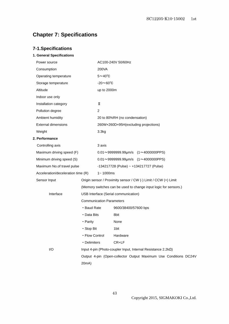
7-1.Specifications 1. General Specifications
Power source AC100-240V 50/60Hz
Consumption 200VA
Operating temperature 5~40
Storage temperature -20~60
Altitude up to 2000m
Indoor use only
Installation category Ⅱ
Pollution degree 2
Ambient humidity 20 to 80%RH (no condensation)
External dimensions 260W×260D×95H(excluding projections)
Weight 3.3kg
2. Performance
Controlling axis 3 axis
Maximum driving speed (F) 0.01~9999999.99µm/s (1~4000000PPS)
Minimum driving speed (S) 0.01~9999999.99µm/s (1~4000000PPS)
Maximum No.of travel pulse -134217728 (Pulse) ~ +134217727 (Pulse)
Acceleration/deceleration time (R) 1~ 1000ms
Sensor Input Origin sensor / Proximity sensor / CW (-) Limit / CCW (+) Limit
(Memory switches can be used to change input logic for sensors.)
Interface USB Interface (Serial communication)
Communication Parameters
・Baud Rate 9600/38400/57600 bps
・Data Bits 8bit
・Parity None
・Stop Bit 1bit
・Flow Control Hardware
・Delimiters CR+LF
I/O Input 4-pin (Photo-coupler Input, Internal Resistance 2.2kΩ)
Output 4-pin (Open-collector Output Maximum Use Conditions DC24V
20mA)

SC12205-K10-15002 1st
44
Copyright 2015, SIGMAKOKI Co.,Ltd.
Control signals Return-to-origin -1 point (photo-coupler input, internal resistance 2.2kΩ)
Emergency stop-1 point (photo-coupler input, internal resistance 2.2kΩ)
Rotation-3 point (photo-coupler input, internal resistance 2.2kΩ)
Reverse rotation-3 point (photo-coupler input, internal resistance 2.2kΩ)
3. Driver Specifications
Driver type Bi-polar pentagon micro-steps system
Driving electric current (output current) 1.4 A/phase (0.75 A/phase)
Current down (stop current) 0.7 A/phase (0.375 A/phase)
Division (micro-step) settings 40 divisions
7-2 Connector Pin Assignments ・・・・7-2-1. I/O Connector
No. Description No. Description
1 24V_EX 11 JOGY-
2 GND_EX 12 -
3 JOGY+ 13 JOGX+
4 - 14 JOGX-
5 STOP 15 ORG
6 IN1 16 IN2
7 IN3 17 IN4
8 JPGZ+ 18 JPGZ-
9 OUT1 19 OUT2
10 OUT3 20 OUT4
Connector 10220-52A2PL (by Sumitomo 3M Limited) used
*) When using the I / O signal, please supply the 24V_ EX (pin 1) and GND_EX (pin 2) than external.
Figure 6-2-1:IN1~4,jpgX-Y-Z,ORG,STOP Input Circuit Diagram
Figure 6-2-2:OUT1~4 Output Circuit Diagram

SC12205-K10-15002 1st
45
Copyright 2015, SIGMAKOKI Co.,Ltd.
・・・・7-2-2. STAGE1,2 Connector No. Description No. Description
1 Blue: motor wiring 9 Autoconfig
2 Red: motor wiring 10 -
3 Orange: motor wiring 11 LS (+): limit detection on +
4 Green: motor wiring 12 LS (-): limit detection on-
5 Black: motor wiring 13 GND: common sensor
6 GND: common sensor 14 NEAR: proximity detection
7 ORG: mechanical origin
detection
15 +24V: sensor power supply
8 +24V: sensor power supply
Female XM3B-1522 connector (OMRON products) used
・・・・7-2-3. USB Connector No. Description No. Description
1 - 3 DATA+
2 DATA- 4 GND
Connector XM7B-0442 (By Omron) used
・7-2-4. OPTION Connector
No. Description No. Description
1 GND 8 GND
2 +5V 9 +5V
3 RXD+ 10 RXD-
4 TXD+ 11 TXD-
5 STOP 12 CONNECT
6 - 13 -
7 - 14 -
Connector 10214-52A2PL (by Sumitomo 3M Limited) used
SC12205-K10-15002 1st
46
Copyright 2015, SIGMAKOKI Co.,Ltd.
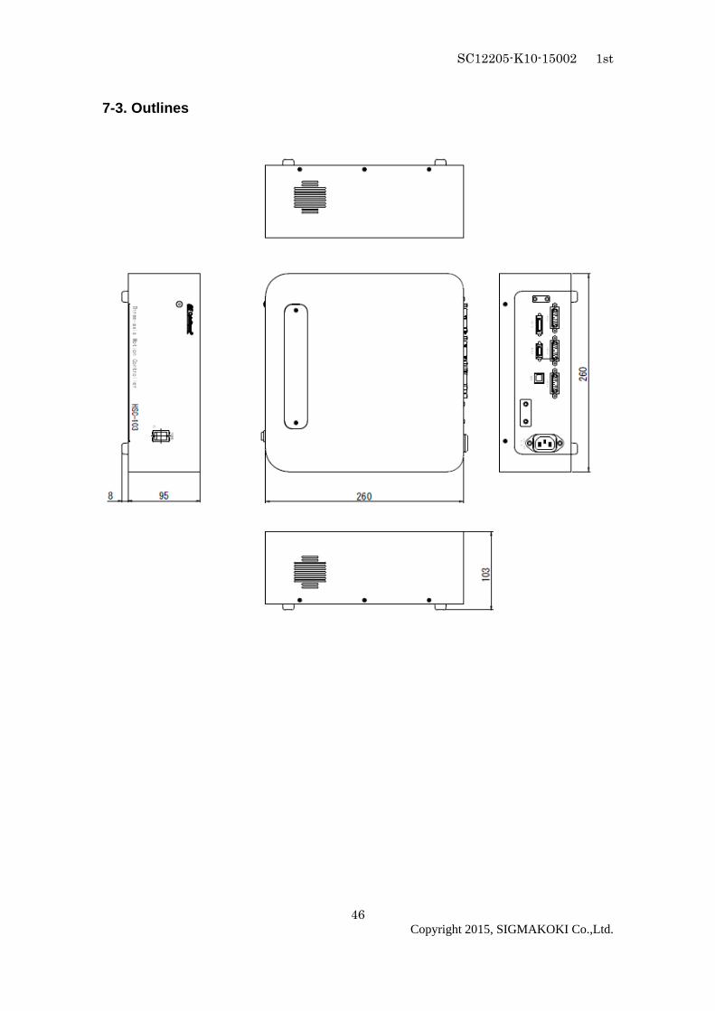
7-3. Outlines

SC12205-K10-15002 1st
47
Copyright 2015, SIGMAKOKI Co.,Ltd.
SIGMAKOKI CO., LTD.
http://www.global-optosigma.com
Tokyo Head Office SIGMAKOKI Tokyo Head office 19-9, Midori 1 chome, Sumida-ku, Tokyo 130-0021, JAPAN
TEL+81-3-5638-8228 FAX+81-3-5638-6550 E-mail:[email protected]
Osaka office 9-28, Nishi-Nakajima 4 chome, Yodogawa-ku, Osaka 532-0011, JAPAN
TEL+81-6-6307-4835 FAX+81-6-6307-4834 E-mail:[email protected]
Kyushu office 3-17,hiemachi, hakata-ku, Fukuoka 812-0014 TEL+81-92-481-4300 FAX+81-92-481-4310 E-mail:[email protected]
Technology Center 1-1Yatsukaho, Hakusan-shi, Ishikawa 924-0838, JAPAN