Embed Size (px)
Citation preview

User’s manualFLIR CM83600 ATrue RMS Power Clamp Meter


User’s manualFLIR CM83
#T559825; r. AI/33557/33557; en-US


Table of contents
1 Disclaimers. . . . . . . . . . . . . . . . . . . . . . . . . . . . . . . . . . . . . . . . . . . . . . . . . . . . . . . . . . . . . . 11.1 Copyright. . . . . . . . . . . . . . . . . . . . . . . . . . . . . . . . . . . . . . . . . . . . . . . . . . . . . . . 11.2 Quality assurance . . . . . . . . . . . . . . . . . . . . . . . . . . . . . . . . . . . . . . . . . . . . . 11.3 Documentation updates . . . . . . . . . . . . . . . . . . . . . . . . . . . . . . . . . . . . . . . 11.4 Disposal of electronic waste. . . . . . . . . . . . . . . . . . . . . . . . . . . . . . . . . . . 1
2 Safety information . . . . . . . . . . . . . . . . . . . . . . . . . . . . . . . . . . . . . . . . . . . . . . . . . . . . . . 22.1 FCC Compliance . . . . . . . . . . . . . . . . . . . . . . . . . . . . . . . . . . . . . . . . . . . . . . 42.2 Industry Canada compliance. . . . . . . . . . . . . . . . . . . . . . . . . . . . . . . . . . 5
3 Introduction . . . . . . . . . . . . . . . . . . . . . . . . . . . . . . . . . . . . . . . . . . . . . . . . . . . . . . . . . . . . . 73.1 Key features. . . . . . . . . . . . . . . . . . . . . . . . . . . . . . . . . . . . . . . . . . . . . . . . . . . . 7
4 Description . . . . . . . . . . . . . . . . . . . . . . . . . . . . . . . . . . . . . . . . . . . . . . . . . . . . . . . . . . . . . . 84.1 Meter parts. . . . . . . . . . . . . . . . . . . . . . . . . . . . . . . . . . . . . . . . . . . . . . . . . . . . . 84.2 Function switch . . . . . . . . . . . . . . . . . . . . . . . . . . . . . . . . . . . . . . . . . . . . . . . . 94.3 Function buttons . . . . . . . . . . . . . . . . . . . . . . . . . . . . . . . . . . . . . . . . . . . . . .104.4 Display icons and indicators . . . . . . . . . . . . . . . . . . . . . . . . . . . . . . . . .11
4.4.1 Out-of-range warning . . . . . . . . . . . . . . . . . . . . . . . . . . . . . .135 Operation . . . . . . . . . . . . . . . . . . . . . . . . . . . . . . . . . . . . . . . . . . . . . . . . . . . . . . . . . . . . . . .14
5.1 Powering the meter . . . . . . . . . . . . . . . . . . . . . . . . . . . . . . . . . . . . . . . . . . .145.1.1 Auto power off. . . . . . . . . . . . . . . . . . . . . . . . . . . . . . . . . . . . . .14
5.2 Auto/Manual select mode . . . . . . . . . . . . . . . . . . . . . . . . . . . . . . . . . . . .145.3 Auto/Manual range mode . . . . . . . . . . . . . . . . . . . . . . . . . . . . . . . . . . . .155.4 Hold mode . . . . . . . . . . . . . . . . . . . . . . . . . . . . . . . . . . . . . . . . . . . . . . . . . . . .15
5.4.1 Smart hold. . . . . . . . . . . . . . . . . . . . . . . . . . . . . . . . . . . . . . . . . .155.5 Silent mode . . . . . . . . . . . . . . . . . . . . . . . . . . . . . . . . . . . . . . . . . . . . . . . . . . .155.6 Voltage and current measurements. . . . . . . . . . . . . . . . . . . . . . . . . .16
5.6.1 Basic voltage measurements . . . . . . . . . . . . . . . . . . . . . .165.6.2 Basic current measurements . . . . . . . . . . . . . . . . . . . . . .165.6.3 Extended functionality . . . . . . . . . . . . . . . . . . . . . . . . . . . . .17
5.7 Non-contact voltage detector . . . . . . . . . . . . . . . . . . . . . . . . . . . . . . . .215.8 Power measurements . . . . . . . . . . . . . . . . . . . . . . . . . . . . . . . . . . . . . . . .21
5.8.1 Single-phase power measurements. . . . . . . . . . . . . . .215.8.2 Three-phase power measurements . . . . . . . . . . . . . . .225.8.3 Phase rotation. . . . . . . . . . . . . . . . . . . . . . . . . . . . . . . . . . . . . .25
5.9 Resistance measurements . . . . . . . . . . . . . . . . . . . . . . . . . . . . . . . . . . .27
#T559825; r. AI/33557/33557; en-US v

Table of contents
5.10 Capacitance measurements . . . . . . . . . . . . . . . . . . . . . . . . . . . . . . . . .275.11 Continuity test. . . . . . . . . . . . . . . . . . . . . . . . . . . . . . . . . . . . . . . . . . . . . . . . .285.12 Diode test . . . . . . . . . . . . . . . . . . . . . . . . . . . . . . . . . . . . . . . . . . . . . . . . . . . . .295.13 Streaming measurement data using Bluetooth . . . . . . . . . . . . . .30
5.13.1 General . . . . . . . . . . . . . . . . . . . . . . . . . . . . . . . . . . . . . . . . . . . . .305.13.2 Procedure . . . . . . . . . . . . . . . . . . . . . . . . . . . . . . . . . . . . . . . . . .30
6 Maintenance. . . . . . . . . . . . . . . . . . . . . . . . . . . . . . . . . . . . . . . . . . . . . . . . . . . . . . . . . . . .316.1 Cleaning and storage. . . . . . . . . . . . . . . . . . . . . . . . . . . . . . . . . . . . . . . . .316.2 Battery replacement . . . . . . . . . . . . . . . . . . . . . . . . . . . . . . . . . . . . . . . . . .31
6.2.1 Disposal of electronic waste . . . . . . . . . . . . . . . . . . . . . . .317 Technical specifications . . . . . . . . . . . . . . . . . . . . . . . . . . . . . . . . . . . . . . . . . . . . . .32
7.1 General specifications. . . . . . . . . . . . . . . . . . . . . . . . . . . . . . . . . . . . . . . .327.2 Electrical specifications . . . . . . . . . . . . . . . . . . . . . . . . . . . . . . . . . . . . . .33
8 Technical support for external meters . . . . . . . . . . . . . . . . . . . . . . . . . . . . . .399 Warranties . . . . . . . . . . . . . . . . . . . . . . . . . . . . . . . . . . . . . . . . . . . . . . . . . . . . . . . . . . . . . .40
9.1 FLIR Global Limited Lifetime Warranty . . . . . . . . . . . . . . . . . . . . . .409.2 FLIR Test and Measurement Limited 2 Year
Warranty . . . . . . . . . . . . . . . . . . . . . . . . . . . . . . . . . . . . . . . . . . . . . . . . . . . . . .41
#T559825; r. AI/33557/33557; en-US vi

1 Disclaimers
1.1 Copyright© 2016, FLIR Systems, Inc. All rights reserved worldwide.No parts of the software including source code may be re-produced, transmitted, transcribed or translated into anylanguage or computer language in any form or by anymeans, electronic, magnetic, optical, manual or otherwise,without the prior written permission of FLIR Systems.
The documentation must not, in whole or part, be copied,photocopied, reproduced, translated or transmitted to anyelectronic medium or machine readable form without priorconsent, in writing, from FLIR Systems.
Names and marks appearing on the products herein areeither registered trademarks or trademarks of FLIR Sys-tems and/or its subsidiaries. All other trademarks, tradenames or company names referenced herein are used foridentification only and are the property of their respectiveowners.
1.2 Quality assuranceThe Quality Management System under which theseproducts are developed and manufactured has been certi-fied in accordance with the ISO 9001 standard.
FLIR Systems is committed to a policy of continuous de-velopment; therefore we reserve the right to makechanges and improvements on any of the products with-out prior notice.
1.3 Documentation updatesOur manuals are updated several times per year, and wealso issue product-critical notifications of changes on aregular basis.
To access the latest manuals and notifications, go to theDownload tab at:
http://support.flir.com
It only takes a few minutes to register online. In the down-load area you will also find the latest releases of manualsfor our other products, as well as manuals for our historicaland obsolete products.
1.4 Disposal of electronic waste
As with most electronic products, this equipment must bedisposed of in an environmentally friendly way, and in ac-cordance with existing regulations for electronic waste.
Please contact your FLIR Systems representative formore details.
#T559825; r. AI/33557/33557; en-US 1

2 Safety information
NOTE
Before operating the device, you must read, understand, and follow all instruc-tions, dangers, warnings, cautions, and notes.
Note FLIR Systems reserves the right to discontinue models, parts or accesso-ries, and other items, or to change specifications at any time without prior notice.
NOTE
Remove the batteries if the device is not used for an extended period of time.
WARNING
Do not operate the device if you do not have the correct knowledge. Formalqualifications and/or national legislation for the electrical inspections can ap-ply. Incorrect operation of the device can cause damage, shock, injury ordeath to persons.
WARNING
Do not start the measuring procedure before you have set the function switchto the correct position. This can cause damage to the instrument and cancause injury to persons.
WARNING
Do not change to current or resistance when you measure the voltage. Thiscan cause damage to the instrument and can cause injury to persons.
WARNING
Do not measure the current on a circuit when the voltage increases to morethan 1000 V. This can cause damage to the instrument and can cause injuryto persons.
#T559825; r. AI/33557/33557; en-US 2

2 Safety information
WARNING
You must disconnect the test leads from the circuit that you did a test on be-fore you change the range. If you do not do this, damage to the instrumentand injury to persons can occur.
WARNING
Do not replace the batteries before you remove the test leads. This can causedamage to the instrument and can cause injury to persons.
WARNING
Do not use the device if the test leads and/or the device show signs of dam-age. Injury to persons can occur.
WARNING
Be careful when you do the measurements if the voltages are more than 25VAC rms or 35 VDC. There is a risk of shock from these voltages. Injury to per-sons can occur.
WARNING
Do not do diode, resistance, or continuity tests before you remove the powerfrom the capacitors and the other devices (when you do a test during a meas-urement). Injury to persons can occur.
WARNING
Do not use the device as a tool to identify live terminals. You must use the cor-rect tools. Injury to persons can occur if you do not use the correct tools.
#T559825; r. AI/33557/33557; en-US 3

2 Safety information
WARNING
Do not touch expired or damaged batteries without gloves. Injury to personscan occur.
WARNING
Do not cause a short-circuit of the batteries. This can cause damage to the in-strument and can cause injury to persons.
WARNING
Do not put the batteries into a fire. Injury to persons can occur.
CAUTION
Do not use the device for a procedure that it is not made for. This can causedamage to the protection.
This symbol, adjacent to another symbol or terminal, indicates thatthe user must refer to the manual for further information.
This symbol, adjacent to a terminal, indicates that, under normaluse, hazardous voltages may be present.
Double insulation.
UL listing is not an indication or a verification of the accuracy of themeter
2.1 FCC Compliance
This device complies with part 15 of the FCC Rules. Operation is subject to thefollowing two conditions:
1. This device may not cause harmful interference.
#T559825; r. AI/33557/33557; en-US 4

2 Safety information
2. This device must accept any interference received, including interferencethat may cause undesired operation.
This equipment has been tested and found to comply with the limits for a Class Bdigital device, pursuant to part 15 of the FCC Rules. These limits are designed toprovide reasonable protection against harmful interference in a residential instal-lation. This equipment generates, uses, and can radiate radio frequency energyand, if not installed and used in accordance with the instructions, may causeharmful interference to radio communications. However, there is no guaranteethat interference will not occur in a particular installation. If this equipment doescause harmful interference to radio or television reception, which can be deter-mined by turning the equipment off and on, the user is encouraged to try to cor-rect the interference by one or more of the following measures:
• Reorient or relocate the receiving antenna.• Increase the separation between the equipment and receiver.• Connect the equipment into an outlet on a circuit different from that to which
the receiver is connected.• Consult the dealer or an experienced radio/TV technician for help.
CAUTION
Exposure to Radio Frequency Radiation.
To comply with FCC/IC RF exposure compliance requirements, a separationdistance of at least 20 cm must be maintained between the antenna of this de-vice and all persons. This device must not be co-located or operating in con-junction with any other antenna or transmitter.
WARNING
Changes or modifications not expressly approved by the party responsible forcompliance could void the user's authority to operate the equipment.
2.2 Industry Canada compliance
This device complies with Industry Canada licence-exempt RSS standard(s). Op-eration is subject to the following two conditions: (1) this device may not cause in-terference, and (2) this devicemust accept any interference, includinginterference that may cause undesired operation of thedevice.
#T559825; r. AI/33557/33557; en-US 5

2 Safety information
CAUTION
Exposure to Radio Frequency Radiation.
To comply with RSS 102 RF exposure compliance requirements, for mobileconfigurations, a separation distance of at least 20 cm must be maintained be-tween the antenna of this device and all persons. This device must not be co-located or operating in conjunction with any other antenna or transmitter.
#T559825; r. AI/33557/33557; en-US 6

3 Introduction
Thank you for choosing a FLIR CM83 clamp meter.
This device is shipped fully tested and calibrated and, with proper use, will pro-vide years of reliable service.
3.1 Key features
• 10 000-count digital display.• Large-scale display.• Analog bar graph.• True RMS reading in AC and AC+DC mode.• Work light.• Auto AC/DC 600 A capability and selection.• Auto AC/DC 1000 V capability and selection.• Auto resistance/continuity/diode selection.• Power and power factor measurement.• Total harmonic distortion and 1 to 25 harmonics.• Phase rotation Indication.• 100 kΩ resistance capability.• Non-contact voltage detector.• Frequency measurement.• Capacitance capability.• Smart data hold.• Peak hold.• In-rush current.• DCA zero key.• Minimum/maximum and average hold.• VFD mode – Low-pass filter.• Auto power off.• Jaw opening 37 mm (1.45") for conductors up to 1500 MCM.• 1.2 m (4′) drop-proof.• Convenient battery cover.• Safety Category Rating: CAT IV-600V, CAT III-1000V.
#T559825; r. AI/33557/33557; en-US 7

4 Description
4.1 Meter parts
Figure 4.1 Front view
1. Clamp jaw.2. Jaw opening trigger.3. Function buttons, see section 4.3 Function buttons, page 10.4. Navigation buttons.5. Non-contact voltage detector light6. Function switch, see section 4.2 Function switch, page 9.7. LCD display.8. Probe terminals.
#T559825; r. AI/33557/33557; en-US 8

4 Description
Figure 4.2 Rear view
1. Work light.2. Battery compartment.
4.2 Function switch
The meter can measure capacitance through the probe inputs.
The meter can measure resistance, continuity, or diode polaritythrough the probe inputs. The type of measurement is selectedby the button.
The meter can measure power through the probe inputs and theclamp jaws.
The meter can measure current through the clamp jaws.
#T559825; r. AI/33557/33557; en-US 9

4 Description
The meter can measure voltage through the probe inputs.
The meter is in full power-saving mode.
4.3 Function buttons
• Use the button to select Auto select or Manual select mode,see section 5.2 Auto/Manual select mode, page 14.
• In Manual select mode, press the button to select the operat-ing mode.
• Use the button to select Auto range or Manual range mode,see section 5.3 Auto/Manual range mode, page 15.
• In Manual range mode, press the button to change the range(scale).
Press the button to toggle between Normal and Hold modes, seesection 5.4 Hold mode, page 15.
Holding the button down for 2 secconds enables/disables the keylock mode.
In Hold mode, the meter will beep continuously and the displaywill flash if the measured signal is larger than the display reading(for the V.A.W. function).
• Press the button to enable/disable the display backlight.• Press and hold the button for 2 seconds to enable/disable the
work light.
Press the button to enable/disable METERLiNK® (Bluetooth)communication, see section 5.13 Streaming measurement datausing Bluetooth, page 30.
#T559825; r. AI/33557/33557; en-US 10

4 Description
4.4 Display icons and indicators
Figure 4.3 Display
Indicates that METERLiNK® (Bluetooth) communication is ac-tive, see section 5.2 Auto/Manual select mode, page 14.
Indicates that the meter is in Auto select mode.
Indicates that the meter is displaying maximum reading values.
Indicates that the meter is displaying minimum reading values.
Indicates that the meter is displaying the average reading.
Indicates that the meter is displaying peak maximum values.
Indicates that the meter is displaying peak minimum values.
Indicates that the meter is in Auto range mode.
Indicates that the meter is in Power factor mode.
Indicates that the meter displays the total harmonic distortion.
#T559825; r. AI/33557/33557; en-US 11

4 Description
Indicates that the meter is in Phase rotation mode.
Indicates that the meter is in Hold mode.
Indicates the battery voltage status.
Indicates that the auto power off function is enabled.
Indicates that the measured voltage is greater than 30 V DC orAC RMS.
Indicates that the meter is measuring AC current or voltage.
Indicates that the meter is measuring DC current or voltage.
Indicates that the meter is measuring AC+DC current or voltage.
Indicates that the continuity function is active.
Indicates that the diode test function is active.
VFD mode icon.
Peak mode icon.
Min/Max/Avg mode icon.
DC Zero mode icon.
Harmonic Distortion icon.
In-rush current mode icon.
Frequency mode icon.
Silent mode icon.
Lock mode icon.
#T559825; r. AI/33557/33557; en-US 12

4 Description
4.4.1 Out-of-range warning
If the input is out-of-range, OL is displayed.
#T559825; r. AI/33557/33557; en-US 13

5 Operation
NOTE
Before operating the device, you must read, understand, and follow all instruc-tions, dangers, warnings, cautions, and notes.
NOTE
When the meter is not in use, the function switch should be set to theposition.
NOTE
When connecting the probe leads to the device under test, connect the nega-tive lead before connecting the positive lead. When removing the probe leads,remove the positive lead before removing the negative lead.
5.1 Powering the meter
1. Set the function switch to any position to switch on the meter.2. If the battery indicator shows that the battery voltage is low or if the me-
ter does not power on, replace the battery. See section 6.2 Battery replace-ment, page 31.
5.1.1 Auto power off
The meter enters sleep mode after 30 minutes of inactivity. The meter beepsthree times 9 seconds before powering off. Press any button or turn the functionswitch to prevent the meter from powering off. The auto power off time-out is thenreset.
To disable auto power off (APO); press the MODE button while turning meter onthe meter.
5.2 Auto/Manual select mode
In Auto select mode, the meter attempts to automatically select the proper oper-ating mode (e.g., AC or DC measurement) based on the input signal. In Manualselect mode, the desired operating mode is selected manually.
#T559825; r. AI/33557/33557; en-US 14

5 Operation
Auto select mode is the default mode of operation. When a new function is se-
lected with the function switch, the starting mode is Auto select and the indi-cator is displayed.
• To enter Manual select mode, press the button. To manually select theoperating mode, press the button repeatedly.
• To enter Auto select mode, press and hold the button until the indi-cator is displayed.
5.3 Auto/Manual range mode
In Auto range mode, the meter automatically selects the most appropriate meas-urement scale. In Manual range mode, the desired range (scale) is set manually.
Auto range mode is the default mode of operation. When a new function is se-
lected with the function switch, the starting mode is Auto range and the indi-cator is displayed.
• To enter Manual range mode, press the button. To change the range,press the button repeatedly until the desired range is displayed.
• To enter Auto range mode, press and hold the button until the indi-cator is displayed.
5.4 Hold mode
In Hold mode, the display freezes the last reading and continues to display thisvalue.
Press the button to toggle between Normal and Hold modes. In Hold
mode, the indicator is displayed.
5.4.1 Smart hold
The meter will beep continuously and the display will flash if the measured signalis larger than the display reading (for the V.A.W. function).
5.5 Silent mode
In Silent mode, the alert beeper is disabled. Silent mode does not affect the con-tinuity beeper.
#T559825; r. AI/33557/33557; en-US 15

5 Operation
1. Use the navigation buttons to select the Silent mode icon , see section5.6.3.1 Selecting the mode, page 17.
5.6 Voltage and current measurements
5.6.1 Basic voltage measurements
NOTE
If the measured voltage is greater than 30 V DC or AC RMS, the indicatoris displayed.
1. Set the function switch to the position.2. To manually select AC, DC, or AC+DC measurement, press the button
repeatedly. Refer to section 5.2 Auto/Manual select mode, page 14.
3. To manually select the measurement range (scale), press the buttonrepeatedly. Refer to section 5.3 Auto/Manual range mode, page 15.
4. Insert the black probe lead into the negative COM terminal and the red probelead into the positive V terminal.
5. Connect the probe leads in parallel to the part under test.6. Read the voltage value on the display.
5.6.2 Basic current measurements
WARNING
Do not measure the current on a circuit when the voltage increases to morethan 1000 V. This can cause damage to the instrument and can cause injuryto persons.
When measuring current using the clamp jaws, only one conductor should be en-closed by the jaws—refer to Figure 5.1.
#T559825; r. AI/33557/33557; en-US 16

5 Operation
Figure 5.1 Correct and incorrect setup
1. Ensure that the probe leads are disconnected from the meter.2. Set the function switch to the position.3. To manually select AC, DC, or AC+DC measurement, press the button
repeatedly. Refer to section 5.2 Auto/Manual select mode, page 14.
4. To manually select the measurement range (scale), press the buttonrepeatedly. Refer to section 5.3 Auto/Manual range mode, page 15.
5. Press the trigger to open the clamp jaws. Fully enclose one conductor—referto Figure 5.1. For optimum results, center the conductor in the jaws.
6. Read the current value on the display.
5.6.3 Extended functionality
In addition to the basic voltage and current measurements, the meter can be setto different modes for extended functionality.
5.6.3.1 Selecting the mode
The mode icons applicable for the selected measurement type are displayed inthe lower part of the display. When a mode is enabled, the icon is framed.
#T559825; r. AI/33557/33557; en-US 17

5 Operation
Figure 5.2 Mode icons (AC voltage measurements): Peak mode and Silentmode are enabled
The navigation buttons are used to select a mode icon and to enable/disable amode:
• Use the and navigation buttons to navigate to a mode icon. The cur-rently selected icon will flash.
• Press the button to enable/disable the selected (flashing) mode.
5.6.3.2 Peak mode
In Peak mode, the meter captures and displays the positive and negative peakvalues, and updates only when a higher/lower value is registered. Peak mode isavailable when measuring AC current or voltage in Manual select mode.
1. Use the navigation buttons to select and enable Peak mode.2. Press the button to toggle between the display of Peak Max and Peak
Min.
• In Peak Max mode, the indicator is displayed.
• In Peak Min mode, the indicator is displayed.
3. Press and hold the button for 2 seconds to disable Peak mode.
5.6.3.3 In-rush current mode
In In-rush current mode, the meter displays the highest current reading in the first100 ms after the trigger point (current detection threshold, see Figure 5.3). Thecurrent detection threshold is 1.00 A for the 100.00 A range and 10.0 A for the1000.0 A range. In-rush current mode is available when measuring AC current inManual select mode.
1. Connect the meter to the unpowered circuit under test.2. Set the function switch to the position.
3. Use the navigation buttons to select and enable In-rush current mode.4. Turn on the power to the circuit under test
#T559825; r. AI/33557/33557; en-US 18

5 Operation
NOTE
If the in-rush current under testing may be more than 100 A AC, manually setthe range to 600 A before activating the in-rush current mode, see section 5.3Auto/Manual range mode, page 15.
Figure 5.3 1: Current; 2: Time; 3: Measured In-rush Current; 4: Current Detec-tion Threshold; 5: 0 A; 6: Start; 7: Stop; 8: 100 ms Sample Window (60 Hz).
5.6.3.4 DC Zero mode
The DC zero feature removes offset values and improves the accuracy for DCcurrent measurements. DC Zero mode is available when measuring DC or AC+DC current in Manual select mode.
1. Ensure that there is no conductor in the clamp jaws.
2. Use the navigation buttons to select and enable DC Zero mode.
5.6.3.5 Frequency mode
In Frequency mode, the meter measures and displays the frequency. Frequencymode is available when measuring AC current or voltage in Manual select mode.
#T559825; r. AI/33557/33557; en-US 19

5 Operation
NOTE
Do not switch to the Frequency mode until the meter is set up and activelymeasuring the voltage or current signal.
1. Use the navigation buttons to select and enable Frequency mode.
5.6.3.6 Min/Max/Avg mode
In Min/Max/Avg mode, the meter captures and displays the minimum or maxi-mum values and updates only when a higher/lower value is registered. The metercan also display the average of all values recorded from the beginning of Min/Max/Avg mode.
1. Use the navigation buttons to select and enable Min/Max/Avg mode.2. Press the button repeatedly to cycle through the minimum, maximum,
and average reading displays. The corresponding icons are displayed: ,
, or .3. Press and hold the button for 2 seconds to disable Min/Max/Avg mode.
5.6.3.7 Harmonic Distortion mode
In Harmonic Distortion mode, the meter displays the distortion percentage valuefor the first 25 harmonics as well as the total harmonic distortion. Harmonic Dis-tortion mode is available when measuring AC current or voltage in Manual selectmode.
The harmonic distortion is expressed as Hn = (RMS of an individual harmonic n)/(RMS of the fundamentals) × 100%.
1. Use the navigation buttons to select and enable Harmonic Distortionmode.
2. While in Harmonic Distortion mode, use the and navigation buttonsto navigate through the individual and total harmonic data. H01, H02, …, Hnis displayed.
3. When the total harmonic distortion is displayed, the indicator appears inthe upper part of the display and 'thd' is shown in the main display.
#T559825; r. AI/33557/33557; en-US 20

5 Operation
4. Press the button to switch the display between Harmonic Order Indica-tion mode and Percentage mode.
5. Press and hold the button for 2 seconds to disable Harmonic Distortionmode.
5.6.3.8 VFD mode – Low-pass filter
In VFD mode, high-frequency noise is eliminated from the voltage measurementby a low-pass filter. VFD mode is intended for measurements on variable-fre-quency drives (VFDs). VFD mode is available when measuring AC current orvoltage in Manual select mode.
1. Use the navigation buttons to select and enable VFD mode.
5.7 Non-contact voltage detector
NOTE
Test on a known live circuit before testing on an unfamiliar circuit.
1. Hold the clamp tips of the meter very close to the voltage source.2. If voltage is present, the non-contact voltage alert lamp (see section 4.1Me-
ter parts, page 8) illuminates a red color.
CAUTION
If the non-contact voltage alert lamp is not illuminated, voltage could stillbe present.
5.8 Power measurements
5.8.1 Single-phase power measurements
1. Set the function switch to the position.2. Insert the black probe lead into the negative COM terminal and the red probe
lead into the positive W terminal.
#T559825; r. AI/33557/33557; en-US 21

5 Operation
3. Press the trigger to open the clamp jaws. Fully enclose one conductor—referto Figure 5.1. For optimum results, center the conductor in the jaws.
NOTE
The + symbol on the jaw should be directed toward the power source.
4. Connect the probe leads in parallel to the part under test.5. Read the active power value on the display.
• If the value is displayed without a sign, the power is flowing from thepower source to the load.
• If the value is displayed with a minus sign (–), the power is flowing fromthe power load to the source.
6. To measure and display the power factor, press the button repeatedly
until the indicator is displayed.7. Read the power factor value on the display.
• If the value is displayed without a sign, the phase of the current signal islagging behind the voltage signal (inductive load).
• If the value is displayed with a minus sign (–), the phase of the current sig-nal is leading the voltage signal (capacitive load).
8. To return to active power measurements, press the button repeatedly
until neither the nor the indicator is displayed.
If an overload occurs, the following is displayed:
• OL. V: Voltage overload or both voltage and current overload.• OL. A: Current overload.• OL. kW: Active power overload.
5.8.2 Three-phase power measurements
5.8.2.1 Three-phase three-wire balanced/unbalanced
The power of a three-phase three-wire delta configuration is measured in twosteps, in accordance with Figure 5.4. The total power is the sum of the two meas-urements:W =W1 +W2.
#T559825; r. AI/33557/33557; en-US 22

5 Operation
Figure 5.4 Three-phase three-wire measurement
1. Set the function switch to the position.
2. Ensure that the meter is set to active power measurement. If the or the
indicator is displayed, press the button repeatedly until none ofthese indicators are displayed.
3. Take two measurements of the active power, in accordance with Figure 5.4.4. To measure and display the power factor, press the button repeatedly
until the indicator is displayed.5. Read the power factor value on the display.
• If the value is displayed without a sign, the phase of the current signal islagging behind the voltage signal (inductive load).
• If the value is displayed with a minus sign (–), the phase of the current sig-nal is leading the voltage signal (capacitive load).
#T559825; r. AI/33557/33557; en-US 23

5 Operation
6. To return to active power measurements, press the button repeatedly
until neither the nor the indicator is displayed.
5.8.2.2 Three-phase four-wire balanced/unbalanced
The power of a three-phase four-wire configuration is measured in three steps,accordance with Figure 5.5. The total power is the sum of the three measure-ments:W =W1 +W2 +W3.
Figure 5.5 Three-phase four-wire measurement
#T559825; r. AI/33557/33557; en-US 24

5 Operation
1. Set the function switch to the position.
2. Ensure that the meter is set to active power measurement. If the or the
indicator is displayed, press the button repeatedly until none ofthese indicators are displayed.
3. Take three measurements of the active power, in accordance with Figure 5.5.4. To measure and display the power factor, press the button repeatedly
until the indicator is displayed.5. Read the power factor value on the display.
• If the value is displayed without a sign, the phase of the current signal islagging behind the voltage signal (inductive load).
• If the value is displayed with a minus sign (–), the phase of the current sig-nal is leading the voltage signal (capacitive load).
6. To return to active power measurements, press the button repeatedly
until neither the nor the indicator is displayed.
5.8.3 Phase rotation
With the meter set to Phase rotation mode, it is possible to determine the phaserotation for a three-wire system.
NOTE
The system frequency must be stable.
#T559825; r. AI/33557/33557; en-US 25

5 Operation
Figure 5.6 Phase rotation
1. Set the function switch to the position.2. Enter Phase rotation mode by pressing the button repeatedly until the
indicator is displayed.3. Connect the red test lead to the presumed phase line 1 and the black test
lead to the presumed phase line 3.4. One of the following results is displayed:
• OLV flashes if the voltage is >1000 V.• Lo V flashes if the voltage is <30 V.• outF flashes if the frequency is >65 Hz or <45 Hz.• If normal, L1 is displayed for about 3 seconds. Then L2 is displayed and
the meter beeps twice.
5. Move the red test lead to the presumed phase line 2 immediately, before"L2" extinguishes from the display.
#T559825; r. AI/33557/33557; en-US 26

5 Operation
6. One of the following results is displayed:
• 123 indicates clockwise or forward rotation, which means that the pre-sumed phase line 1 is ahead of the presumed phase line 2.
• 321 indicates counterclockwise or reversed rotation, which means thatthe presumed phase line 2 is ahead of the presumed phase line 1.
• - - - means that the meter is unable to determine the results.• Lo Vmeans that users possibly removed the test leads before completing
the testing procedure. To repeat the test, press the OK button again.
5.9 Resistance measurements
WARNING
Do not do diode, resistance, or continuity tests before you remove the powerfrom the capacitors and the other devices (when you do a test during a meas-urement). Injury to persons can occur.
1. Set the function switch to the position.2. Ensure that the meter is set to resistance measurement. If the or the
indicator is displayed, press the button repeatedly until none of theseindicators are displayed.
3. Insert the black probe lead into the negative COM terminal and the red probelead into the positive Ω terminal.
4. Touch the tips of the probe across the circuit or component under test.5. Read the resistance value on the display.
5.10 Capacitance measurements
WARNING
Do not take capacitance measurements before you have removed the powerfrom the capacitor or other device or circuit during a test. Injury to persons canoccur.
#T559825; r. AI/33557/33557; en-US 27

5 Operation
NOTE
To protect the internal components, if a capacitor that is being tested has acharge, the meter will first discharge the cap and show diSC. After a completedischarge the meter will conduct a normal test. diSCmay also be displayed ifthe incorrect input is provided (e.g., measuring voltage while in capacitancemode).
1. Set the function switch to the position.2. Insert the black probe lead into the negative COM terminal and the red probe
lead into the positive terminal.3. Touch the tips of the probe across the part under test.4. Read the capacitance value on the display.
NOTE
For very large capacitance values, it may take several seconds for themeasurement to settle and the final reading to stabilize.
5.11 Continuity test
WARNING
Do not do diode, resistance, or continuity tests before you remove the powerfrom the capacitors and the other devices (when you do a test during a meas-urement). Injury to persons can occur.
1. Set the function switch to the position.2. Insert the black probe lead into the negative COM terminal and the red probe
lead into the positive Ω terminal.3. Use the button to select continuity measurement. The indicator will
be displayed.4. Touch the tips of the probe across the circuit or component under test.5. If the resistance is less than 30 Ω, the meter will beep.
#T559825; r. AI/33557/33557; en-US 28

5 Operation
5.12 Diode test
WARNING
Do not do diode, resistance, or continuity tests before you remove the powerfrom the capacitors and the other devices (when you do a test during a meas-urement). Injury to persons can occur.
The meter checks diodes using an alternating test signal sent through the diodein both directions. This allows the user to check the diode without having to re-verse the polarity manually. The meter display will show ±0.4–0.8V for a good di-ode, bAd for a shorted diode, and O.L for an opened diode. See Figure 5.7.
- 0.4V
O.LbAd + 0.4V
Figure 5.7 Diode testing
1. Set the function switch to the position.2. Insert the black probe lead into the negative COM terminal and the red probe
lead into the positive Ω terminal.3. Use the button to select the diode test function. The indicator will
be displayed.4. Touch the tips of the probe across the diode or semiconductor junction under
test.5. If the reading is between ±0.40 and +0.80 V, the component is good; an bAd
or O.L display indicates a defective component.
#T559825; r. AI/33557/33557; en-US 29

5 Operation
5.13 Streaming measurement data using Bluetooth
5.13.1 General
Some IR cameras from FLIR Systems support Bluetooth communication, and tothose cameras you can stream measurement data from the meter. The data isthen merged into the result table in the IR image.
Streaming measurement data is a convenient way to add important informationto an IR image. For example, when identifying an overheated cable connection,you may want to know the current in that cable.
The Bluetooth range is 10m (32ft) maximum.
5.13.2 Procedure
1. Pair the IR camera with the instrument. Refer to the camera manual for infor-mation on how to pair Bluetooth devices.
2. Turn on the camera.3. Turn on the meter.4. Press the on the meter to enable Bluetooth.5. Choose the variable that you want to use (voltage, current, resistance, etc.).
Results from the meter will now automatically be displayed in the result tablein the top left corner of the IR camera screen.
#T559825; r. AI/33557/33557; en-US 30

6 Maintenance
6.1 Cleaning and storage
Clean the meter with a damp cloth and mild detergent; do not use abrasives orsolvents.
If the meter is not to be used for an extended period, remove the batteries andstore them separately.
6.2 Battery replacement
1. To avoid electrical shock, disconnect the meter if connected to a circuit, re-move the probe/thermocouple leads from the terminals, and set the functionswitch to the position before attempting to replace the batteries.
2. Unscrew and remove the battery compartment cover.3. Replace the six standard AAA batteries, observing correct polarity.4. Secure the battery compartment cover.
6.2.1 Disposal of electronic waste
As with most electronic products, this equipment must be disposed of in an envi-ronmentally friendly way, and in accordance with existing regulations for elec-tronic waste.
Please contact your FLIR Systems representative for more details.
#T559825; r. AI/33557/33557; en-US 31

7 Technical specifications
7.1 General specifications
Display count: 10 000 or 4000.
Measuring rate: 3 times per second.
Over-range indication: OL or –OL.
Auto power off: Approx. 30 minutes.
Low battery indicator: is displayed. Replace the battery when the indicatorappears in the display.
Power requirement: 6 × 1.5 VAAA alkaline batteries.
Battery life: Approx. 50 hours with alkaline batteries (backlight, work light, andBluetooth are off).
Environmental conditions: Indoor use.
Calibration: 1 year calibration cycle.
Operating temperatures:
• 0 to 10 (32 to 50)(non-condensing)• 10 to 30 (50 to 86) (≦ 80% RH)• 30 to 40 (86 to 104) (≦ 75% RH)• 40 to 50 (104 to 122) (≦ 45%RH)
Storage temperature:
• –10 to 50 (14 to 122).• 0–80% RH (batteries not fitted).
Dimensions (H × W × L): 49 mm × 100 mm × 262 mm (1.9″ × 3.9″ × 10.3″).
Weight: 0.59 kg (1.29 lb.), including batteries.
Bluetooth range: 10 m (32 ft.) maximum.
Temperature coefficient: 0.2 × (specified accuracy)/, <18, >28.
Over-voltage category: IEC 61010-1 CAT IV-600 V, CAT III-1000 V, IEC 61010-2-033.
#T559825; r. AI/33557/33557; en-US 32
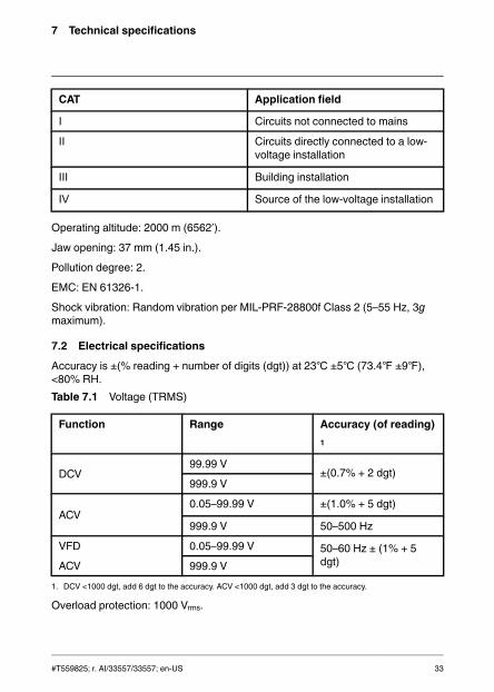
7 Technical specifications
CAT Application field
Ⅰ Circuits not connected to mains
Ⅱ Circuits directly connected to a low-voltage installation
Ⅲ Building installation
Ⅳ Source of the low-voltage installation
Operating altitude: 2000 m (6562ʹ).
Jaw opening: 37 mm (1.45 in.).
Pollution degree: 2.
EMC: EN 61326-1.
Shock vibration: Random vibration per MIL-PRF-28800f Class 2 (5–55 Hz, 3gmaximum).
7.2 Electrical specifications
Accuracy is ±(% reading + number of digits (dgt)) at 23 ±5 (73.4 ±9),<80% RH.Table 7.1 Voltage (TRMS)
Function Range Accuracy (of reading)1
DCV99.99 V
±(0.7% + 2 dgt)999.9 V
ACV0.05–99.99 V ±(1.0% + 5 dgt)
999.9 V 50–500 Hz
VFD
ACV
0.05–99.99 V 50–60 Hz ± (1% + 5dgt)999.9 V
1. DCV <1000 dgt, add 6 dgt to the accuracy. ACV <1000 dgt, add 3 dgt to the accuracy.
Overload protection: 1000 Vrms.
#T559825; r. AI/33557/33557; en-US 33

7 Technical specifications
Input impedance: 3.5 MΩ //, <100 pF.
AC conversion type: AC coupled, true RMS responding, calibrated to the RMSvalue of a sine wave input. Accuracies are given for sine waves at full scale andnon-sine waves below half scale. For non-sine waves (50/60 Hz), add the follow-ing crest factor corrections:
• For a crest factor of 1.4–2.0, add 1.0% to the accuracy.• For a crest factor of 2.0–2.5, add 2.5% to the accuracy.• For a crest factor of 2.5–3.0, add 4.0% to the accuracy.
CF:
• 3 @ 460 V, 280 A.• 2 @ 690 V, 420 A.
AC+DC Vrms accuracy: Same as ACV specification + DCV specification.
Table 7.2 Current (TRMS)
Function Range Accuracy
DCA99.99 A ±(2% + 0.5 A)
599.9 A ±(2% + 5 dgt)*
ACA
0.10–99.99 A 50–60 Hz ± (2% + 5dgt)*
>60–400 Hz ± (2.5% +5 dgt)*
599.9 A
VFD
ACA
0.10–99.99 A 50–60 Hz ± (2% + 5dgt)*599.9 A
* For measured values <1000 dgt, add 5 dgt to the accuracy.
Overload protection: 600 Arms.
Position error: ±1% of reading.
AC conversion type and additional accuracy is same as for the AC voltage.
AC+DC Arms accuracy: Same as ACA specification + DCA specification. TheDCA is affected by the temperature and the residual magnetism. Use the DCAzero function to compensate.
#T559825; r. AI/33557/33557; en-US 34

7 Technical specifications
Table 7.3 Peak hold: peak maximum/peak minimum (AC only, Non TRMS)
Function Range Accuracy
ACV140.0 V
±(3.0% + 15 dgt)1400 V
ACA140.0 A
±(3.5% + 15 dgt)850 A
Overload protection: 1000 Vrms , 600 ArmsPeak Hold Response time: 200μs
Accuracy defined for sine waves, ACV > 5 Vrms/ACA ≧ 5 Arms, frequency 50–400Hz. Only suitable for repetitive events.
Table 7.4 Frequency
Function Range Accuracy
Frequency20.00–99.99 Hz
±(0.5% + 3 dgt)20.0–999.9 Hz
0.020–9.999 kHz
Overload protection: 1000 Vrms, 600 Arms.
Sensitivity:
• 10–100 Vrms for AC 100 V range.• 10–100 Arms for AC 100 A range (>400 Hz unspecified).• 100–1000 Vrms for AC 1000 V range.• 100–600 Arms for AC 600 A range (>400 Hz unspecified).
The reading will be 0.0 for signals below 10.0 Hz.
Table 7.5 Total harmonic distortion
Function Range Accuracy
ACA/ACV 99.9% ±(3.0% + 10 dgt)
#T559825; r. AI/33557/33557; en-US 35

7 Technical specifications
Table 7.6 Harmonic distortion measurement
Harmonic order Range Accuracy
H01–H1299.9%
±(5% + 10 dgt)
H13–H25 ±(10% + 10 dgt)
Overload protection: 1000 Vrms, 600 Arms• If ACV < 10 Vrms or ACA < 10 Arms, rdy is displayed.• If the fundamental frequency is outside the range 45–65Hz, out.F is displayed.
Table 7.7 Inrush current
Function Range Accuracy
ACA99.99 A ±(3% + 0.3 A)
599.9 A ±(3% + 5 dgt)*
* For measured values <1000 dgt, add 5 dgt to the accuracy.
Overload protection: 1000 Vrms, 600 Arms.
Accuracy is defined for sine waves, ACA ≧ 10 Arms, rreq. 50/60 Hz. Integrationtime approx. 100 ms.
#T559825; r. AI/33557/33557; en-US 36

7 Technical specifications
Table 7.8 Active power: watts (DC/AC)
Function Range1
Accuracy
DCW
9.999 kW (10 V, 5 Amin) ±(3% + 0.05 kW)
99.99 kW (10 V, 5 Amin)
±(3% + 0.5 kW)
599.9 kW (10 V, 5 Amin)
±(3% + 10 dgt)
ACW
9.999 kW (10 V, 5 Amin)
±(3% + 10 dgt)99.99 kW (10 V, 5 Amin)
599.9 kW (10 V, 5 Amin)
1. The range is determined by the V/A range (9.999 kW: 100 V,100 A; 99.99 kW: 1000 V,100 A, or 100 V, 600A; 599.9 kW: 1000 V, 600 A).
Overload protection: 1000 Vrms, 600 Arms.
Accuracy defined for:
• ACW:
Sine waves, ACV ≧ 10 Vrms, ACA ≧ 5 Arms. Frequency 50–60 Hz, PF = 1.00.
• DCW: DCV ≧ 10 V, DCA ≧ 5 A.Table 7.9 Power factor
Function Range Accuracy
PF –1.00 to 0.00 to +1.00 ±3° ± 1 dgt
Overload protection: 1000 Vrms, 600 Arms.
#T559825; r. AI/33557/33557; en-US 37

7 Technical specifications
Table 7.10 Resistance and continuity and diode
Function Range Accuracy
Resistance
999.9 Ω ±(1.0% + 5 dgt)
9.999 kΩ±(1.0% + 3 dgt)
99.99 kΩ
Continuity 999.9 Ω ±(1.0% + 5 dgt)
Diode 0.40–0.80 V ±0.1V
Overload protection: 1000 Vrms.
Maximum test current: Approx. 0.5 mA.
Maximum open circuit voltage for Ω: Approx. 2.4 V.
Maximum open circuit voltage for diode: Approx. ±1.6 V.
Continuity threshold:
• <30 Ω beep on.• >100 Ω beep off.
Continuity indicator: 2 kHz tone buzzer.
Continuity response time: <100 ms.
Table 7.11 Capacitance
Function Range Accuracy
Capacitance
3.999 μF
±(1.9% + 8 dgt)39.99 μF
399.9 μF
3.999 mF
Overload protection: 1000 Vrms.
#T559825; r. AI/33557/33557; en-US 38

8 Technical support for external meters
Website http://www.flir.com/test
Technical support [email protected]
Repairs [email protected]
Phone number +1 855-499-3662 (toll-free)
#T559825; r. AI/33557/33557; en-US 39

9 Warranties
9.1 FLIR Global Limited LifetimeWarrantyA qualifying FLIR Test and Measurement product (the“Product”) purchased either directly from FLIR Commer-cial Systems Inc and affiliates (FLIR) or from an author-ized FLIR distributor or reseller that Purchaser registerson-line with FLIR is eligible for coverage under FLIR’s Lim-ited Lifetime Warranty, subject to the terms and conditionsin this document. This warranty only applies to purchasesof Qualifying Products (see below) purchased and manu-factured after April 1, 2013.
PLEASE READ THIS DOCUMENT CAREFULLY; IT CON-TAINS IMPORTANT INFORMATION ABOUT THE PROD-UCTS THATQUALIFY FOR COVERAGE UNDER THELIMITED LIFETIME WARRANTY, PURCHASER’S OBLI-GATIONS, HOW TO ACTIVATE THE WARRANTY, WAR-RANTYCOVERAGE, AND OTHER IMPORTANT TERMS,CONDITIONS, EXCLUSIONS AND DISCLAIMERS.
1. PRODUCT REGISTRATION. To qualify for FLIR’s Lim-ited Lifetime Warranty, Purchaser must fully register theProduct directly with FLIR on-line at http://www.flir.comwithin Sixty (60) DAYS of the date the Product was pur-chased by the first retail customer (the “Purchase Date”).Qualifying PRODUCTS THATARE NOT REGISTEREDON-LINE WITHIN SIXTY (60) DAYS OF THE PURCHASEDATE WILL HAVE A LIMITED ONE YEARWARRANTYFROM DATE OF PURCHASE.
2. QUALIFYING PRODUCTS. Upon registration, Test andMeasurement products that qualify for coverage underFLIR’s Limited Lifetime Warranty are: MR7x, CM7x,CM8x, DMxx, VP5x not including accessories which mayhave their own warranty.
3. WARRANTY PERIODS. For purposes of the The Lim-ited Lifetime Warranty, Lifetime is defined as seven years(7) after the product is no longer manufactured, or tenyears (10) from date of purchase, whichever is greater.This Warranty is only applicable to the original owner ofthe Products.
Any Product that is repaired or replaced under warranty iscovered under this Limited Lifetime Warranty for one hun-dred eighty days (180) days from the date of return ship-ment by FLIR or for the remaining duration of theapplicable Warranty Period, whichever is longer.
4. LIMITEDWARRANTY. In accordance with the termsand conditions of this Limited Lifetime Warranty, and ex-cept as excluded or disclaimed in this document, FLIRwarrants, from the Purchase Date, that all fully registeredProducts will conform to FLIR’s published Product specifi-cations and be free from defects in materials and work-manship during the applicable Warranty Period.PURCHASER’S SOLE AND EXCLUSIVE REMEDYUNDER THISWARRANTY, AT FLIR’S SOLE DISCRE-TION, IS THE REPAIR OR REPLACEMENT OF
DEFECTIVE PRODUCTS IN A MANNER, AND BYASERVICE CENTER, AUTHORIZED BY FLIR. IF THISREMEDY IS ADJUDICATED TO BE INSUFFICIENT, FLIRSHALL REFUND PURCHASER’S PAID PURCHASEPRICE AND HAVE NO OTHER OBLIGATION OR LIABIL-ITY TO BUYERWHATSOEVER.
5. WARRANTY EXCLUSIONS AND DISCLAIMERS.FLIR MAKES NO OTHERWARRANTYOFANY KINDWITH RESPECT TO THE PRODUCTS. ALL OTHERWARRANTIES, EXPRESS OR IMPLIED, INCLUDINGBUT NOT LIMITED TO IMPLIEDWARRANTIES OF MER-CHANTABILITY, FITNESS FOR A PARTICULAR PUR-POSE (EVEN IF PURCHASER HAS NOTIFIED FLIR OFITS INTENDED USE FOR THE PRODUCTS), AND NON-INFRINGEMENTARE EXPRESSLY EXCLUDED FROMTHIS AGREEMENT.
THISWARRANTY EXPRESSLY EXCLUDES ROUTINEPRODUCT MAINTENANCE, SOFTWARE UPDATES,AND REPLACEMENT OF MANUALS, FUSES, OR DIS-POSABLE BATTERIES. FLIR FURTHER EXPRESSLYDISCLAIMS ANYWARRANTYCOVERAGEWHERETHE ALLEGED NONCONFORMITY IS DUE TO NOR-MALWEAR AND TEAR, OTHER ALTERATION, MODIFI-CATION, REPAIR, ATTEMPTED REPAIR, IMPROPERUSE, IMPROPER MAINTENANCE, NEGLECT, ABUSE,IMPROPER STORAGE, FAILURE TO FOLLOWANYPRODUCT INSTRUCTIONS, DAMAGE (WHETHERCAUSED BYACCIDENT OR OTHERWISE), OR ANYOTHER IMPROPER CARE OR HANDING OF THEPRODUCTS CAUSED BYANYONE OTHER THAN FLIROR FLIR’S EXPRESSLYAUTHORIZED DESIGNEE.
THIS DOCUMENT CONTAINS THE ENTIRE WAR-RANTYAGREEMENT BETWEEN PURCHASER ANDFLIR AND SUPERSEDES ALL PRIORWARRANTY NE-GOTIATIONS, AGREEMENTS, PROMISES ANDUNDERSTANDINGS BETWEEN PURCHASER ANDFLIR. THIS WARRANTY MAY NOT BE ALTEREDWITH-OUT THE EXPRESSWRITTEN CONSENT OF FLIR.
6. WARRANTY RETURN, REPAIR AND REPLACE-MENT. To be eligible for warranty repair or replacement,Purchaser must notify FLIR within thirty (30) days of dis-covering of any apparent defect in materials or workman-ship. Before Purchaser may return a Product for warrantyservice or repair, Purchaser must first obtain a returnedmaterial authorization (RMA) number from FLIR. To obtainthe RMA number Owner must provide an original proof ofpurchase. For additional information, to notify FLIR of anapparent defect in materials or workmanship, or to requestan RMA number, visit http://www.flir.com. Purchaser issolely responsible for complying with all RMA instructionsprovided by FLIR including but not limited to adequatelypackaging the Product for shipment to FLIR and for allpackaging and shipping costs. FLIR will pay for returningto Purchaser any Product that FLIR repairs or replacesunder warranty.
#T559825; r. AI/33557/33557; en-US 40

9 Warranties
FLIR reserves the right to determine, in its sole discretion,whether a returned Product is covered under Warranty. IfFLIR determines that any returned Product is not coveredunder Warranty or is otherwise excluded from Warrantycoverage, FLIR may charge Purchaser a reasonable han-dling fee and return the Product to Purchaser, at Purchas-er’s expense, or offer Purchaser the option of handling theProduct as a non-warranty return.
7. NON-WARRANTY RETURN. Purchaser may requestthat FLIR evaluate and service or repair a Product not cov-ered under warranty, which FLIR may agree to do in itssole discretion. Before Purchaser returns a Product fornon-warranty evaluation and repair, Purchaser must con-tact FLIR by visiting http://www.flir.com to request an eval-uation and obtain an RMA. Purchaser is solelyresponsible for complying with all RMA instructions pro-vided by FLIR including but not limited to adequatelypackaging the Product for shipment to FLIR and for allpackaging and shipping costs. Upon receipt of an author-ized non-warranty return, FLIR will evaluate the Productand contact Purchaser regarding the feasibility of and thecosts and fees associated with Purchaser’s request. Pur-chaser shall be responsible for the reasonable cost ofFLIR’s evaluation, for the cost of any repairs or servicesauthorized by Purchaser, and for the cost of repackagingand returning the Product to Purchaser.
Any non-warranty repair of a Product is warranted for onehundred eighty days (180) days from the date of returnshipment by FLIR to be free from defects in materials andworkmanship only, subject to all of the limitations, exclu-sions and disclaimers in this document.
9.2 FLIR Test and MeasurementLimited 2 Year WarrantyA qualifying FLIR Test and Measurement product (the“Product”) purchased either directly from FLIR Commer-cial Systems Inc and affiliates (FLIR) or from an author-ized FLIR distributor or reseller that Purchaser registerson-line with FLIR is eligible for coverage under FLIR’s Lim-ited Warranty, subject to the terms and conditions in thisdocument. This warranty only applies to purchases ofQualifying Products (see below) purchased and manufac-tured after April 1, 2013.
PLEASE READ THIS DOCUMENT CAREFULLY; IT CON-TAINS IMPORTANT INFORMATION ABOUT THE PROD-UCTS THATQUALIFY FOR COVERAGE UNDER THELIMITEDWARRANTY, PURCHASER’S OBLIGATIONS,HOW TO ACTIVATE THE WARRANTY, WARRANTYCOVERAGE, AND OTHER IMPORTANT TERMS, CON-DITIONS, EXCLUSIONS AND DISCLAIMERS.
1. PRODUCT REGISTRATION. To qualify for FLIR’s Lim-ited Warranty, Purchaser must fully register the Product di-rectly with FLIR on-line at http://www.flir.com within Sixty(60) DAYS of the date the Product was purchased by thefirst retail customer (the “Purchase Date”). QualifyingPRODUCTS THATARE NOT REGISTERED ON-LINE
WITHIN SIXTY (60) DAYS OF THE PURCHASE DATEWILL HAVE A LIMITED ONE YEARWARRANTY FROMDATE OF PURCHASE.
2. QUALIFYING PRODUCTS. Upon registration, Test andMeasurement products that qualify for coverage underFLIR’s Limited Warranty are: VS70 Videoscope, VSAxxArticulation Camera, VSCxx Camera, VSSxx Probe Spool,VST handset, MR02 Pin Extension Probe, and TAxx notincluding accessories which may have their own warranty.
3. WARRANTY PERIODS. The applicable Limited War-ranty Period measured from the Purchase data are:
Products Limited WarrantyPeriod
VS70, VSAxx, VSCxx,VSSxx, VST, MR02,TAxx
TWO (2) Years
Any Product that is repaired or replaced under warranty iscovered under this Limited Warranty for one hundredeighty days (180) days from the date of return shipmentby FLIR or for the remaining duration of the applicableWarranty Period, whichever is longer.
4. LIMITEDWARRANTY. In accordance with the termsand conditions of this Limited Warranty, and except as ex-cluded or disclaimed in this document, FLIR warrants,from the Purchase Date, that all fully registered Productswill conform to FLIR’s published product specificationsand be free from defects in materials and workmanshipduring the applicable Warranty Period. PURCHASER’SSOLE AND EXCLUSIVE REMEDY UNDER THISWAR-RANTY, AT FLIR’S SOLE DISCRETION, IS THE REPAIROR REPLACEMENT OF DEFECTIVE PRODUCTS IN AMANNER, AND BYA SERVICE CENTER, AUTHORIZEDBY FLIR. IF THIS REMEDY IS ADJUDICATED TO BE IN-SUFFICIENT, FLIR SHALL REFUND PURCHASER’SPAID PURCHASE PRICE AND HAVE NO OTHER OBLI-GATION OR LIABILITY TO BUYERWHATSOEVER.
5. WARRANTY EXCLUSIONS AND DISCLAIMERS.FLIR MAKES NO OTHERWARRANTYOFANY KINDWITH RESPECT TO THE PRODUCTS. ALL OTHERWARRANTIES, EXPRESS OR IMPLIED, INCLUDINGBUT NOT LIMITED TO IMPLIEDWARRANTIES OF MER-CHANTABILITY, FITNESS FOR A PARTICULAR PUR-POSE (EVEN IF PURCHASER HAS NOTIFIED FLIR OFITS INTENDED USE FOR THE PRODUCTS), AND NON-INFRINGEMENTARE EXPRESSLY EXCLUDED FROMTHIS AGREEMENT.
THISWARRANTY EXPRESSLY EXCLUDES ROUTINEPRODUCT MAINTENANCE, SOFTWARE UPDATES,AND REPLACEMENT OF FUSES, OR DISPOSABLEBATTERIES. FLIR FURTHER EXPRESSLY DISCLAIMSANY WARRANTYCOVERAGE WHERE THE ALLEGEDNONCONFORMITY IS DUE TO NORMALWEAR ANDTEAR, OTHER ALTERATION, MODIFICATION, REPAIR,ATTEMPTED REPAIR, IMPROPER USE, IMPROPER
#T559825; r. AI/33557/33557; en-US 41

9 Warranties
MAINTENANCE, NEGLECT, ABUSE, IMPROPER STOR-AGE, FAILURE TO FOLLOWANY PRODUCT INSTRUC-TIONS, DAMAGE (WHETHER CAUSED BYACCIDENTOR OTHERWISE), OR ANYOTHER IMPROPER CAREOR HANDING OF THE PRODUCTS CAUSED BYANY-ONE OTHER THAN FLIR OR FLIR’S EXPRESSLYAU-THORIZED DESIGNEE.
THIS DOCUMENT CONTAINS THE ENTIRE WAR-RANTYAGREEMENT BETWEEN PURCHASER ANDFLIR AND SUPERSEDES ALL PRIORWARRANTY NE-GOTIATIONS, AGREEMENTS, PROMISES ANDUNDERSTANDINGS BETWEEN PURCHASER ANDFLIR. THISWARRANTY MAY NOT BE ALTEREDWITH-OUT THE EXPRESSWRITTEN CONSENT OF FLIR.
6. WARRANTY RETURN, REPAIR AND REPLACE-MENT. To be eligible for warranty repair or replacement,Purchaser must notify FLIR within thirty (30) days of dis-covering of any apparent defect in materials or workman-ship. Before Purchaser may return a Product for warrantyservice or repair, Purchaser must first obtain a returnedmaterial authorization (RMA) number from FLIR. To obtainthe RMA number Owner must provide an original proof ofpurchase. For additional information, to notify FLIR of anapparent defect in materials or workmanship, or to requestan RMA number, visit http://www.flir.com. Purchaser issolely responsible for complying with all RMA instructionsprovided by FLIR including but not limited to adequatelypackaging the Product for shipment to FLIR and for allpackaging and shipping costs. FLIR will pay for returningto Purchaser any Product that FLIR repairs or replacesunder warranty.
FLIR reserves the right to determine, in its sole discretion,whether a returned Product is covered under Warranty. IfFLIR determines that any returned Product is not coveredunder Warranty or is otherwise excluded from Warrantycoverage, FLIR may charge Purchaser a reasonable han-dling fee and return the Product to Purchaser, at Purchas-er’s expense, or offer Purchaser the option of handling theProduct as a non-warranty return.
7. NON-WARRANTY RETURN. Purchaser may requestthat FLIR evaluate and service or repair a Product not cov-ered under warranty, which FLIR may agree to do in itssole discretion. Before Purchaser returns a Product fornon-warranty evaluation and repair, Purchaser must con-tact FLIR by visiting http://www.flir.com to request an eval-uation and obtain an RMA. Purchaser is solelyresponsible for complying with all RMA instructions pro-vided by FLIR including but not limited to adequatelypackaging the Product for shipment to FLIR and for allpackaging and shipping costs. Upon receipt of an author-ized non-warranty return, FLIR will evaluate the Productand contact Purchaser regarding the feasibility of and thecosts and fees associated with Purchaser’s request. Pur-chaser shall be responsible for the reasonable cost ofFLIR’s evaluation, for the cost of any repairs or servicesauthorized by Purchaser, and for the cost of repackagingand returning the Product to Purchaser.
Any non-warranty repair of a Product is warranted for onehundred eighty days (180) days from the date of returnshipment by FLIR to be free from defects in materials andworkmanship only, subject to all of the limitations, exclu-sions and disclaimers in this document.
#T559825; r. AI/33557/33557; en-US 42


A note on the technical production of this publicationThis publication was produced using XML — the eXtensible Markup Language.For more information about XML, please visit http://www.w3.org/XML/A note on the typeface used in this publicationThis publication was typeset using Linotype Helvetica™World. Helvetica™ wasdesigned by Max Miedinger (1910–1980)LOEF (List Of Effective Files)T501025.xml; en-US; AI; 33557; 2016-02-18
#T559825; r. AI/33557/33557; en-US 44


last page
Publ. No.: T559825Release: AICommit: 33557Head: 33557Language: en-USModified: 2016-02-18Formatted: 2016-02-18
Websitehttp://www.flir.comCustomer supporthttp://support.flir.comCopyright© 2016, FLIR Systems, Inc. All rights reserved worldwide.DisclaimerSpecifications subject to change without further notice. Models and accessoriessubject to regional market considerations. License procedures may apply.Products described herein may be subject to US Export Regulations. Pleaserefer to [email protected] with any questions.