Embed Size (px)
Citation preview

®
User’s HandbookManuale Dell’utenteGebruikershandboek
GBPart No TPD 1397EID
M92
M115T
I
D


TPD1397EID Title
Perkins M92 and M115T Marine Diesel Engines/Perkins M92 e M115T Motori diesel marini/Perkins M92 en M115T scheepsdieselmotoren
User’s handbook/Manuale dell’utente/Gebruikershandboek
Four cylinder diesel engine for commercial and pleasure boat applications/Motore diesel a quattro cilindri per uso commerciale e per imbarcazioni da diporto/4-cilinder dieselmotor voor beroeps- en pleziervaart
Publication TPD 1397EID, Issue 9.© Proprietary information of Wimborne Marine Power Centre, all rights reserved. The information is correct at the time of print. Published in December 2013 by Wimborne Marine Power Centre, Wimborne, Dorset, BH21 7PW EnglandTel: +44(0)1202 796000 Fax: +44(0)1202 796001 E-mail: [email protected] www.perkins.com/marine
Pubblicazione TPD 1397EID, Edizione 9.© Informazione di proprietà della Wimborne Marine Power Centre, tutti i diritti riservati. Le informazioni sono corrette al momento della stampa. Pubblicato nel dicembre 2013 da Wimborne Marine Power Centre, Wimborne, Dorset BH21 7PW, InghilterraTel: +44(0)1202 796000. Fax: +44(0)1202 796001. E-mail: [email protected] www.perkins.com/marine
Publication TPD 1397EID, Issue 9.(c) Deze informatie is eigendom van Wimborne Marine Power Centre - alle rechten voorbehouden. In dit handboek is de meest actuele stand van zaken beschreven zoals bekend bij het ter perse gaan. Gepubliceerd in Dezember 2013 door Wimborne Marine Power Centre, Dorset BH21 7PW, Groot-BrittanniëTel: +44(0)1202 796000. Fax: +44(0)1202 796001. E-mail: [email protected] www.perkins.com/marine

Title TPD1397EID

TPD1397EID Contents
1General informationIntroduction .......................................................................................................................1How to care for your engine .............................................................................................2Safety precautions ............................................................................................................3Engine guarantee .............................................................................................................5Engine identification .........................................................................................................5Perkins companies ...........................................................................................................6
2 Engine viewsIntroduction .......................................................................................................................9Location of engine parts .................................................................................................10
Front and left side view (A) of an M92 engine .......................................................10Rear and right side view (B) of an M92 engine ......................................................11
Location of engine parts .................................................................................................12Front and left side view (A) of an M115T engine ...................................................12Rear and right side view (B) of an M115T engine ..................................................13
3 Operation instructionsHow to use the control panel ..........................................................................................15Utilisation ........................................................................................................................15Auxiliary control panel ....................................................................................................17Fuse panel ......................................................................................................................18To renew fuses (A1, A2 and A3) .....................................................................................18Start retard mechanism ..................................................................................................19How to start the engine...................................................................................................20Preparations for an engine start .....................................................................................20How to start a cold engine in cold conditions .................................................................21How to start a warm engine, or if the ambient temperature is hotter than -10OC (14OF). 21How to stop the engine ...................................................................................................22Adjustment of engine speed range .................................................................................22Running-in ......................................................................................................................22Angle of tilt ......................................................................................................................22Free rotation of the propeller shaft or “trailing” ...............................................................23Operation of the lever for gear selection .......................................................................23Newage PRM 500D reverse gearbox (A) .......................................................................23ZF-Hurth HBW 450A (B) .................................................................................................23Emergency procedures ..................................................................................................24If the engine stops ..........................................................................................................24If there is a reduction in engine speed or a loss of power ..............................................24If the warning lamp / audible warning for high coolant temperature operates ................24If a high-pressure fuel pipe is broken or has a crack ......................................................25If leakage occurs from a low pressure fuel pipe .............................................................25If leakage of lubricating oil occurs: .................................................................................25

Contents TPD1397EID
4 Preventive maintenancePreventive maintenance periods ....................................................................................27Schedules .......................................................................................................................28Programme .....................................................................................................................29How to fill the coolant circuit ...........................................................................................31How to drain the coolant circuit ......................................................................................32Engines fitted with keel coolers ......................................................................................32How to check the specific gravity of the coolant .............................................................33Specific gravity chart ......................................................................................................33How to drain the raw water system ................................................................................35How to check the impeller of the raw water pump ..........................................................36How to check the drive belt ............................................................................................38How to adjust the belt tension ........................................................................................38How to renew the element of the fuel filter .....................................................................39Fuel pre-filter ..................................................................................................................40Atomiser maintenance ....................................................................................................40Atomiser fault..................................................................................................................40How to renew an atomiser ..............................................................................................41How to eliminate air from the fuel system.......................................................................42How to renew the lubricating oil......................................................................................43How to renew the canister of the lubricating oil filter ......................................................45How to renew the lubricating oil of the Newage PRM 500D reverse gearbox ................46How to renew the lubricating oil of the ZF-HSW 450A reverse gearbox ........................48How to renew the engine breather assembly .................................................................50How to renew the element of the air filter .......................................................................51M92 engines ...................................................................................................................51M115T Engines ...............................................................................................................51How to set the valve tip clearances ................................................................................53Seacock strainer .............................................................................................................55Corrosion ........................................................................................................................55Supplementary tools .......................................................................................................55Power take-off ................................................................................................................56
5 Engine fluidsFuel specification ............................................................................................................57Low temperature fuels ....................................................................................................58Lubricating oil specification.............................................................................................59Viscosity chart ................................................................................................................59Coolant specification ......................................................................................................60
6 Fault diagnosisProblems and possible causes .......................................................................................62List of possible causes ...................................................................................................63

TPD1397EID Contents
7 Engine preservationIntroduction .....................................................................................................................69Procedure .......................................................................................................................69How to add antifreeze to the raw water system for engine preservation purposes ........71
8 Parts and serviceIntroduction .....................................................................................................................73Service literature.............................................................................................................73Training ...........................................................................................................................73On-board spares kit ........................................................................................................73POWERPART recommended consumable products......................................................74
9 General dataEngine ............................................................................................................................77Reverse gearbox ............................................................................................................77

Contents TPD1397EID

TPD1397EID Indice
1 GénéralitésIntroduction .......................................................................................................................1Información general ..........................................................................................................1Soins et entretien du moteur ............................................................................................2Consignes générales de sécurité .....................................................................................3Garantie du moteur...........................................................................................................5Identification du moteur ....................................................................................................5Les représentants Perkins ................................................................................................6
2 Vues du moteurIntroduction .......................................................................................................................9Emplacement des composants du moteur .....................................................................10Vue de l’avant et du côté gauche (A) du moteur M92 ....................................................10Vue de l’arrière et du côté droit (B) du moteur M92 .......................................................11Emplacement des composants du moteur .....................................................................12Vue de l’avant et du côté gauche (A) du moteur M115T ................................................12Vue de l’arrière et du côté droit (B) d’un moteur M115T .................................................13
3 UtilisationUtilisation du tableau de bord .........................................................................................15Tableau de bord auxiliaire...............................................................................................17Panel de control auxiliar .................................................................................................17Planche à fusibles ..........................................................................................................18Pour remplacer les fusibles (A1, A2 et A3) .....................................................................18Panel de fusibles ............................................................................................................18Mécanisme retardateur...................................................................................................19Mise en marche du moteur .............................................................................................20Préparations à la mise en marche du moteur.................................................................20Mise en marche du moteur froid par temps froid ............................................................21Mise en marche d’un moteur chaud, ou quand la température ambiante est supérieure à -10OC ..............................................................................................................................21Arrêt du moteur...............................................................................................................22Réglage de la plage de régime du moteur .....................................................................22Rodage ...........................................................................................................................22Angle d’inclinaison ..........................................................................................................22Rotation libre de l’arbre de l’hélice .................................................................................23Fonctionnement du levier de vitesses ............................................................................23Inverseur Newage PRM 500D (A) ..................................................................................23Inverseur ZF-Hurth HBW 450A (B) .................................................................................23Mesures d’urgence .........................................................................................................24En cas d’arrêt du moteur ................................................................................................24En cas de diminution du régime moteur ou de perte de puissance. ..............................24Si le voyant/signal sonore de haute tem-pérature de liquide de refroidissement est activé : 24En cas de rupture ou fissure d’un tuyau de carburant haute pression ...........................25

Indice TPD1397EID
En cas de fuite provenant d’un tuyau de carburant basse pression ...............................25En cas de fuite d’huile de graissage : .............................................................................25
4 Entretien préventifPériodes d’entretien préventif .........................................................................................27Remplissage du circuit de refroidissement .....................................................................31Vidange du circuit de refroidissement ............................................................................32Moteurs équipés de refroidisseurs de quille ...................................................................32Contrôle de la densité du liquide de refroidissement .....................................................33Tableau de densité .........................................................................................................33Vidange du circuit d’eau brute ........................................................................................35Contrôle du rotor de pompe à eau brute ........................................................................36Contrôle de la courroie d’entraînement ..........................................................................38Réglage de la tension de la courroie ..............................................................................38Remplacement de l’élément du filtre à carburant ...........................................................39Pré-filtre à carburant .......................................................................................................40Entretien des injecteurs ..................................................................................................40Défaut d’injecteur............................................................................................................40Prefiltro de combustible ..................................................................................................40Purge du circuit d’alimentation .......................................................................................42Remplacement de l’huile de graissage du moteur .........................................................43Remplacement de la cartouche de filtre à huile de graissage ........................................45Remplacement de l’huile de graissage de l’inverseur Newage PRM 500D ...................46Remplacement de l’huile de graissage de l’inverseur ZF-HSW 450A ............................48Remplacement de l’ensemble reniflard du moteur .........................................................50Remplacement de l’élément de filtre à air ......................................................................51Moteurs M92...................................................................................................................51Moteurs M115T ...............................................................................................................51Contrôle du jeu des poussoirs ........................................................................................53Crépine de vanne de coque ...........................................................................................55Outils supplémentaires ...................................................................................................55Prise de force .................................................................................................................56
5 Liquides utilisés dans le moteurSpécification du carburant ..............................................................................................57Carburants pour basses températures ...........................................................................58Spécification de l’huile de graissage ..............................................................................59Tableau des viscosités....................................................................................................59Spécification du liquide de refroidissement ....................................................................60Especificación del refrigerante .......................................................................................60
6 Diagnostic des défautsProblèmes et causes possibles ......................................................................................64Liste des causes possibles .............................................................................................65

TPD1397EID Indice
7 Arrêt prolongé du moteurIntroduction .....................................................................................................................69Procédure .......................................................................................................................69Addition d’antigel dans le circuit d’eau brute en vue de l’arrêt prolongé du moteur .......71
8 Pièces et entretienIntroduction .....................................................................................................................73Documentation de service ..............................................................................................73Kit de pièces détachées de bord ....................................................................................73
9 Caractéristiques généralesMoteur ............................................................................................................................78Inverseur.........................................................................................................................78

Indice TPD1397EID

TPD1397EID Inhoud
1 Información generalIntroducción ......................................................................................................................1Cuidado de su motor ........................................................................................................2Medidas de seguridad ......................................................................................................3Garantía del motor............................................................................................................5Identificación del motor.....................................................................................................5Empresas Perkins ............................................................................................................6
2 Vista detallada del motorIntroducción ......................................................................................................................9Emplazamiento de los componentes del motor..............................................................10Vista delantera y lateral izquierda (A) de un motor M92. ...............................................10Vista trasera y lateral derecha (B) de un motor M92 ......................................................11Emplazamiento de los componentes del motor..............................................................12Vista delantera y lateral izquierda (A) de un motor M115T.............................................12Vista trasera y lateral derecha (B) de un motor M115T ..................................................13
3 Instrucciones de funcionamientoCómo utilizar el panel de control ....................................................................................15Panel de control auxiliar .................................................................................................17Panel de fusibles ............................................................................................................18Para sustituir fusibles (A1, A2 y A3) ...............................................................................18Mecanismo de retardo del arranque...............................................................................19Cómo arrancar el motor..................................................................................................20Preparativos para el arranque del motor ........................................................................20Cómo arrancar un motor frío en condiciones frías .........................................................21Cómo arrancar un motor caliente, o si la temperatura ambiente es superior a -10OC. ..21Cómo parar el motor.......................................................................................................22Ajuste de la gama de velocidades del motor ..................................................................22Rodaje ............................................................................................................................22Ángulo de inclinación......................................................................................................22Giro libre del eje de transmisión o “arrastre” ..................................................................23Accionamiento de la palanca de cambios ......................................................................23Inversor Newage PRM 500D (A) ....................................................................................23ZF-Hurth HBW 450A (B) .................................................................................................23Procedimientos de emergencia ......................................................................................24Si el motor se para .........................................................................................................24Si el motor pierde velocidad o potencia..........................................................................24Si se enciende el testigo o se activa el aviso acústico de alta temperatura de refrigerante. ...............................................................................................................24Si un tubo de alta presión de combustible está roto o agrietado: ..................................25Si se produce una fuga de una tubería de combustible de baja presión .......................25Si hay pérdidas de aceite lubricante:..............................................................................25

Inhoud TPD1397EID
4 Mantenimiento preventivoIntervalos de mantenimiento preventivo .........................................................................27Programas de mantenimiento ........................................................................................30Cómo llenar el circuito de refrigerante............................................................................31Cómo drenar el circuito de refrigerante ..........................................................................32Motores con sistema de refrigeración en la quilla ..........................................................32Cómo medir el peso específico del refrigerante .............................................................33Cómo drenar el sistema de agua cruda .........................................................................35Cómo comprobar el impulsor de la bomba de agua cruda ............................................36Cómo revisar la correa motriz ........................................................................................38Cómo ajustar la tensión de la correa ..............................................................................38Cómo sustituir el cartucho del filtro de combustible .......................................................39Mantenimiento de los inyectores ....................................................................................40Fallo de uno de los inyectores ........................................................................................40Cómo sustituir un inyector ..............................................................................................41Cómo purgar el aire del sistema de combustible ...........................................................42Cómo cambiar el aceite lubricante .................................................................................43Cómo sustituir el cartucho del filtro de aceite lubricante ................................................45Cómo cambiar el aceite lubricante del inversor Newage PRM 500D .............................46Cómo cambiar el aceite lubricante del inversor ZF-HSW 450A .....................................48Cómo cambiar el conjunto respiradero del motor...........................................................50Cómo sustituir el cartucho del filtro de aire ....................................................................51Motores M92...................................................................................................................51Motores M115T ...............................................................................................................51Cómo ajustar la holgura de válvulas ..............................................................................53Outils supplémentaires ...................................................................................................55Colador del grifo de mar .................................................................................................55Corrosión ........................................................................................................................55Herramientas suplementarias.........................................................................................55Toma de fuerza ...............................................................................................................56
5 Líquidos del motorEspecificaciones del combustible ...................................................................................57Combustibles para temperaturas bajas ..........................................................................58Especificaciones del aceite lubricante ............................................................................59Tabla de viscosidad ........................................................................................................59
6 Diagnosis de averíasProblèmes et causes possibles ......................................................................................64Liste des causes possibles .............................................................................................65Problemas y sus posibles causas ..................................................................................66

TPD1397EID Inhoud
7 Conservación del motorLista de causas posibles ................................................................................................67IIntroducción ...................................................................................................................69Procedimientos ...............................................................................................................69Cómo añadir anticongelante al sistema de agua cruda para fines de conservación del motor ..............................................................................................................................71
8 Piezas y servicioIntroducción ....................................................................................................................73Documentación Técnica .................................................................................................73Formación.......................................................................................................................73Juego de repuestos de a bordo ......................................................................................73
9 Datos generalesMotor ..............................................................................................................................79Inversor...........................................................................................................................79

Inhoud TPD1397EID

TPD1397EID Chapter 1
17
General informationIntroductionThe Perkins M92 and M115T marine engines are the latest development from Perkins Engines Company Limited together with Wimborne Marine Power Centre. The engines are designed specifically for use in commercial and pleasure boat applications.Over sixty years of diesel production experience, together with the latest technology, have been applied to the manufacture of your engine to give you reliable and economic power.Danger is indicated in the text by two methods:Warning! This indicates that there is a possible danger to the person.Caution: This indicates that there is a possible danger to the engine.Note: Is used where the information is important, but there is not a danger.
Informazioni generaliIntroduzioneI motori marini M92 e M115T Perkins sono uno dei più recenti sviluppi nati dagli accordi commerciali tra la Perkins Engines Company Limited e la Wimborne Marine Power Centre. Questi motori sono stati specificamente progettati per impiego su barche commerciali e per diporto.Più di sessant’anni di esperienza nella produzione di motori diesel e l’impiego delle più moderne tecnologie hanno reso possibile la realizzazione di questo motore in grado di offrirvi una potenza affidabile ed economica.Nel testo sono stati adottati due metodi per indicare situazioni pericolose:Pericolo! Indica una situazione di pericolo per le persone.Attenzione: Indica una situazione di pericolo per il motore.Nota: Viene usata per fornire informazioni importanti, ma non indica un pericolo.
Algemene informatieInleidingDe Perkins M92 en M115T scheepsmotoren zijn de nieuwste producten van Perkins Engines Company Limited, ontwikkeld in samenwerking met Wimborne Marine Power Centre. De motoren zijn speciaal ontworpen voor gebruik in de beroeps- en de pleziervaart.Meer dan zestig jaar ervaring op het gebied van de productie van dieselmotoren en kennis van de meest recente ontwikkelingen op dat gebied zijn gebundeld bij de ontwikkeling en bouw van uw motor, om u een betrouwbare en zuinige krachtbron te kunnen bieden.In de tekst wordt op de volgende twee manieren op gevaar gewezen:Waarschuwing! Dit geeft aan dat gevaar op persoonlijk letsel bestaat. Voorzichtig: Dit geeft aan dat de motor beschadigd kan raken.Let op: Wordt gebruikt voor belangrijke informatie waar geen sprake is van gevaar.

Chapter 1 TPD1397EID
18
How to care for your engineWarning! Read the “Safety precautions” and remember them. They are given for your protection and must be applied at all times.Caution: Do not clean an engine while it runs. If cold cleaning fluids are applied to a hot engine, certain components on the engine may be damaged.This handbook has been written to assist you to maintain and operate your engine correctly.To obtain the best performance and the longest life from your engine, you must ensure that the maintenance operations are done at the intervals indicated in “Preventive maintenance”. If the engine works in a very dusty environment or other adverse conditions, certain maintenance intervals will have to be reduced. Renew the filter canister and lubricating oil regularly in order to ensure that the inside of your engine remains clean.Ensure that all adjustments and repairs are done by personnel who have had the correct training. Perkins distributors have this type of personnel available. You can also obtain parts and service from your Perkins distributor. If you do not know the address of your nearest distributor, enquire at Wimborne Marine Power Centre, see page 7.The “left side” and “right side” of the engine apply when the engine is seen from the reverse gearbox end.
Come aver cura del motorePericolo! Leggere le “Precauzioni di sicurezza” e ricordarle. Esse vengono infatti fornite per la vostra protezione personale e devono sempre essere osservate.Attenzione: Non pulire un motore durante il funzionamento. L’eventuale uso di liquidi detergenti freddi su di un motore caldo, può causare danni ad alcuni componenti del motore.Questo manuale è stato redatto per aiutarvi nella manutenzione e nell’impiego corretti del motore.Per ottenere le migliori prestazioni e la più lunga durata del motore, è necessario effettuare gli interventi di manutenzione agli intervalli indicati nella “Manutenzione preventiva”. Se il motore viene fatto funzionare in ambienti molto polverosi o in altre condizioni sfavorevoli, è necessario ridurre l’intervallo tra gli interventi di manutenzione. Sostituire regolarmente la cartuccia del filtro e l’olio lubrificante in modo che l’interno del motore rimanga pulito.Assicurarsi che tutte le registrazioni e le riparazioni siano eseguite da personale opportunamente addestrato. I Concessionari Perkins hanno a loro disposizione personale di questo tipo. Il concessionario Perkins può anche fornire assistenza e parti di ricambio. Se non si conosce l’indirizzo del Concessionario più vicino, rivolgersi alla Wimborne Marine Power Centre, vedere pag. 7.I termini “lato sinistro” e “lato destro” del motore si riferiscono a un motore visto dal lato dell’invertitore.
Onderhoud van uw motorWaarschuwing! De veiligheidsmaatregelen moeten gelezen en worden opgevolgd. Ze zijn voor uw eigen veiligheid en moeten altijd in acht worden genomen.Caution: Geen draaiende motor schoonmaken. Wanneer koude reinigingsmiddelen worden gebruikt op een hete motor, kunnen sommige motoronderdelen beschadigd raken.Deze handleiding is geschreven om u te helpen bij het onderhoud en de juiste bediening van uw motor.Om de beste prestaties en een lange levensduur van uw motor te waarborgen, dient u ervoor te zorgen dat de onderhoudsbeurten worden uitgevoerd op de tijdstippen die staan aangegeven onder “Preventief onderhoud”. Als de motor wordt gebruikt in een zeer stoffige omgeving of onder andere zware omstandigheden, dient het onderhoud vaker plaats te vinden. Vervang regelmatig de filterelementen en de olie om ervoor te zorgen dat het inwendige van de motor schoon blijft.Zorg ervoor dat alle aanpassingen en elke reparatie wordt uitgevoerd door personeel dat daartoe is opgeleid. Bij de Perkins importeur of dealer is dat altijd het geval. Daar kunt u ook terecht voor service en onderdelen. Indien u het adres van de dichtstbijzijnde dealer niet weet, kunt u dit navragen bij Wimborne Marine Power Centre, zie pagina 7.De “linkerkant” en “rechterkant” van de motor zijn gezien vanaf de zijde van de keerkoppeling.

TPD1397EID Chapter 1
19
Safety precautionsThese safety precautions are important. You must refer also to the local regulations in the country of use. Some items only apply to specific applications.• Only use these engines in the type of
application for which they have been designed.
• Do not change the specification of the engine.
• Do not smoke when you put fuel into the tank.
• Clean away fuel which has been spilt. Material which has been contaminated by fuel must be moved to a safe place.
• Do not put fuel into the tank while the engine runs (unless it is absolutely necessary).
• Do not clean, add lubricating oil, or adjust the engine while it runs (unless you have had the correct training; even then extreme care must be used to prevent injury).
• Do not make adjustments that you do not understand.
• Ensure that the engine does not run in a location where it can cause a concentration of toxic emissions.
• Other persons must be kept at a safe distance while the engine, auxiliary equipment or boat is in operation.
• Do not permit loose clothing or long hair near moving parts.
Warning! Some moving parts cannot be seen clearly while the engine runs.• Keep away from moving parts during
engine operation.• Do not operate the engine if a safety
guard has been removed.• Do not remove the filler cap or any
component of the cooling system while the engine is hot and while the coolant is under pressure, because dangerous hot coolant can be discharged.
• Do not use salt water or any other coolant which can cause corrosion in the closed circuit of the cooling system.
Precauzioni di sicurezzaQueste precauzioni di sicurezza sono importanti. Consultare anche i regolamenti locali vigenti nel paese d’impiego. Alcune voci si riferiscono soltanto ad applicazioni specifiche.• Usare questi motori soltanto per il
genere di applicazione per cui sono stati progettati.
• Non modificare le caratteristiche tecniche del motore.
• Non fumare mentre si versa il combustibile nel serbatoio.
• Pulire il combustibile versato. I materiali contaminati dal combustibile devono essere trasferiti in un luogo sicuro.
• Non versare combustibile nel serbatoio quando il motore è acceso (a meno che non sia assolutamente necessario).
• Non pulire, aggiungere olio lubrificante o mettere a punto il motore mentre è acceso (a meno che non si sia ricevuto un addestramento adeguato e anche in questo caso prestare la massima attenzione per evitare infortuni).
• Non eseguire delle registrazioni che non si comprendono.
• Assicurarsi che il motore non venga fatto funzionare in un luogo dove può causare una concentrazione di emissioni tossiche.
• Gli estranei devono essere mantenuti a una distanza di sicurezza durante il funzionamento del motore, dell’equipaggiamento ausiliario o della barca.
• Non lasciare che indumenti sciolti o capelli lunghi si avvicinino troppo alle parti in movimento.
Pericolo! Alcune parti in movimento non sono chiaramente visibili durante il funzionamento del motore.• Tenersi lontano dalle parti in movimento
durante il funzionamento del motore.• Non avviare il motore se una delle
protezioni è stata rimossa.• Non togliere il tappo di rifornimento o
un altro componente dell’impianto di raffreddamento a motore caldo e con il liquido refrigerante sotto pressione, dato che si potrebbe verificare la pericolosa fuoriuscita di liquido bollente.
• Non usare acqua salata o nessun altro tipo di liquido refrigerante che possa causare corrosione nel circuito chiuso dell’impianto di raffreddamento.
• Non provocare scintille o avvicinare fiamme vive alla batteria (specialmente quando è sotto carica) dato che il gas sprigionato dall’elettrolito è molto infiammabile.
• Il liquido della batteria è pericoloso per la pelle e specialmente per gli occhi.
VeiligheidsmaatregelenDeze veiligheidsmaatregelen zijn belangrijk. U dient tevens te letten op de plaatselijk geldende bepalingen in het land van gebruik. Sommige delen hebben slechts betrekking op specifieke toepassingen.• De motoren uitsluitend gebruiken voor
het doel waarvoor zij zijn ontworpen.• De specificatie van de motor niet
veranderen.• Niet roken bij het vullen van de tank.• Gemorste brandstof direct verwijderen.
Materiaal dat door brandstof is verontreinigd, moet naar een veilige plaats worden overgebracht.
• De tank niet met brandstof vullen terwijl de motor draait (tenzij dit absoluut noodzakelijk is).
• Niet reinigen, motorolie bijvullen of de motor afstellen terwijl de motor draait (tenzij u de juiste opleiding heeft gehad, hoewel zelfs dan uiterst voorzichtig te werk moet worden gegaan om persoonlijk letsel te voorkomen).
• Geen afstellingen verrichten die u niet begrijpt.
• Ervoor zorgen dat de motor niet draait in een omgeving waarin uitlaatgassen zich kunnen ophopen (verstikkingsgevaar).
• Andere personen op een veilige afstand houden zolang de motor, de hulpuitrusting of de boot in bedrijf is.
• Loshangende kleding of lang haar uit de buurt van bewegende delen houden.
Waarschuwing! Sommige bewegende delen zijn niet duidelijk zichtbaar wanneer de motor draait.• Blijf uit de buurt van bewegende delen
wanneer de motor draait.• De motor niet gebruiken met
verwijderd(e) veiligheidsscherm(en).• De vuldop van het koelsysteem of een
ander deel van het koelsysteem niet verwijderen zolang de motor heet is en de koelvloeistof onder druk staat, omdat gevaarlijke, hete koelvloeistof naar buiten kan spuiten.
• Geen zout water of andere koelvloeistof die corrosie in het gesloten circuit van het koelsysteem kan veroorzaken, gebruiken.
• Vuur en vonken uit de buurt van de accu’s (in het bijzonder wanneer deze worden opgeladen) houden, omdat gassen afkomstig van de elektrolyt, licht ontvlambaar zijn.
• Het accuzuur is gevaarlijk voor de huid en vooral voor de ogen.
• De accupolen loskoppelen voordat reparaties aan het elektrisch systeem worden uitgevoerd.
Chapter 1 TPD1397EID
20
• Do not allow sparks or fire near the batteries (especially when the batteries are on charge) because the gases from the electrolyte are highly flammable.
• The battery fluid is dangerous to the skin and especially to the eyes.
• Disconnect the battery terminals before a repair is made to the electrical system.
• Only one person must control the engine.
• Ensure that the engine is operated only from the control panel or from the operators position.
• If your skin comes into contact with high-pressure fuel, obtain medical assistance immediately.
• Diesel fuel and lubricating oil (especially used lubricating oil) can damage the skin of certain persons. Protect your hands with gloves or a special solution to protect the skin.
• Do not wear clothing which is contaminated by lubricating oil. Do not put material which is contaminated with oil into the pockets of clothing.
• Discard used lubricating oil in accordance with local regulations to prevent contamination.
• Ensure that the control lever of the transmission drive is in the “out-of-drive” position before the engine is started.
• Use extreme care if emergency repairs must be made at sea or in adverse conditions.
• The combustible material of some components of the engine (for example certain seals) can become extremely dangerous if it is burned. Never allow this burnt material to come into contact with the skin or with the eyes.
• Always close the seacock before the removal of any component of the raw water circuit.
• Always use a safety cage to protect the operator when a component is to be pressure tested in a container of water. Fit safety wires to secure the plugs which seal the hose connections of a component which is to be pressure tested.
• Do not allow compressed air to contact your skin. If compressed air enters your skin, obtain medical help immediately.
• Turbochargers operate at high speed and at high temperature. Keep fingers, tools and debris away from inlet and outlet ports of the turbocharger and prevent contact with hot surfaces.
• Do not clean an engine while it runs. If cold cleaning fluids are applied to a hot engine, certain components on the engine may be damaged.
• Fit only genuine Perkins parts.
• Scollegare i morsetti della batteria prima di eseguire una riparazione sull’impianto elettrico.
• Deve esserci un solo addetto al controllo del motore.
• Assicurarsi che il motore venga fatto funzionare solo dal quadro di comando o dal posto di guida.
• Se il combustibile sotto pressione colpisce la pelle, rivolgersi immediatamente alle cure di un medico.
• Il gasolio e l’olio lubrificante (specialmente l’olio usato) possono essere nocivi alla pelle di certe persone. Proteggere le mani con guanti o con una crema protettiva speciale.
• Non indossare indumenti contaminati da olio lubrificante. Non mettere in tasca materiale contaminato da olio lubrificante.
• Smaltire l’olio lubrificante usato nel pieno rispetto della normativa vigente per evitare contaminazioni.
• Assicurarsi che la leva di comando del cambio sia in posizione di folle prima di avviare il motore.
• Prestare la massima attenzione se si devono eseguire riparazioni di emergenza in mare o in condizioni difficili.
• Il materiale combustibile di alcuni componenti del motore (ad esempio alcune tenute) può diventare estremamente pericoloso se viene bruciato. Non permettere mai che questo materiale bruciato venga a contatto di pelle o occhi.
• Chiudere sempre la presa dell’acqua di mare prima di smontare qualsiasi componente del circuito dell’acqua bruta.
• Usare sempre una gabbia di sicurezza per proteggere il meccanico quando un componente deve essere sottoposto a una prova a pressione in un bagno d’acqua. Attaccare dei cavi di sicurezza per fissare i tappi che sigillano i raccordi dei flessibili di un componente da sottoporre a una prova a pressione.
• Non lasciare che l’aria compressa venga a contatto della pelle. Se l’aria compressa dovesse penetrare nella pelle, rivolgersi immediatamente a un medico.
• I turbocompressori funzionano a velocità e temperature elevate. Tenere dita, attrezzi e detriti lontano dalle luci di entrata e di uscita del turbocompressore ed evitare il contatto con le superfici calde.
• Non pulire un motore durante il funzionamento. L’eventuale uso di liquidi detergenti freddi su di un motore caldo, può causare danni ad alcuni componenti del motore.
• Usare solo ricambi originali Perkins.
• Slechts één persoon mag de motor bedienen.
• Ervoor zorgen dat de motor wordt bediend vanaf het bedieningspaneel of vanuit de positie van de bediener.
• Indien de huid in contact komt met brandstof onder hoge druk, onmiddellijk medische hulp inroepen.
• Dieselolie en motorolie (vooral afgewerkte olie) kan bij bepaalde personen leiden tot huidbeschadiging. Bescherm de handen met speciale handschoenen of een speciale huidbeschermende oplossing.
• Geen kleding dragen die is verontreinigd met motorolie. Geen materiaal dat verontreinigd is met motorolie in zakken van kleding stoppen.
• Afgewerkte olie naar een daartoe bestemde plaats afvoeren conform de ter plekke geldende voorschriften, om vervuiling te voorkomen.
• Ervoor zorgen dat de bedieningshendel van de transmissie in “vrij” staat voordat de motor wordt gestart.
• Uiterst voorzichtig te werk gaan bij noodreparaties op zee of onder moeilijke omstandigheden.
• Brandbaar materiaal van bepaalde motoronderdelen (zoals bepaalde pakkingen) kan na verbranding buitengewoon gevaarlijk zijn. Ervoor zorgen dat dit verbrande materiaal nooit met de huid of de ogen in aanraking komt.
• De buitenboordkraan altijd dichtdraaien voordat een object uit het buitenboordwatercircuit wordt verwijderd.
• Altijd een veiligheidskooi gebruiken ter bescherming van de bediener bij het onder druk, in water, testen van onderdelen. Bevestig veiligheidsdraden voor het vastzetten van de stoppen die de aansluitnippels afsluiten van het onderdeel dat onder druk wordt getest.
• Ervoor zorgen dat perslucht niet met de huid in aanraking komt. Als perslucht de huid binnendringt, moet onmiddellijk medische hulp worden ingeroepen.
• Turbocompressoren werken op een hoog toerental en hebben een hoge bedrijfstemperatuur. Vingers, gereedschap en rommel dan ook uit de buurt van de in- en uitlaatpoorten van de turbocompressor houden en ervoor zorgen dat contact met hete oppervlakken wordt voorkomen.
• Geen draaiende motor schoonmaken. Wanneer koude reinigingsmiddelen worden gebruikt op een hete motor, kunnen sommige motoronderdelen beschadigd raken.
• Uitsluitend originele Perkins onderdelen monteren.

TPD1397EID Chapter 1
21
Engine guaranteeIf a claim under guarantee is necessary, the boat owner should make a guarantee claim on the nearest Perkins marine distributor or an approved dealer.If it is difficult to find a Perkins distributor or an approved dealer, consult the Service Department of Wimborne Marine Power Centre. For further details see page 7.
Engine identificationM92 engine - identification letters ARM115T engine - identification letters AKThe engine identification number is shown at two locations on the engine: stamped on a plate at the rear of the right side of the cylinder block (A) and shown on a label (B1) fitted to the front of the timing case.An example of an engine number is: AR30495U123456F.The components of the engine number are as follows:AR30495U123456FAR Type code letters 30459 Build list number U Built in the UK 123456 Engine serial number F Year of manufactureIf you need parts, service or information for your engine, you must give the complete engine number to your Perkins distributor.
Garanzia sul motoreSe è necessario inoltrare una richiesta di rimborso in garanzia, il proprietario deve rivolgersi al Concessionario Perkins marino più vicino oppure ad un rivenditore autorizzato.Se è difficile localizzare un Concessionario Perkins o un rivenditore autorizzato, rivolgersi al Reparto di assistenza della Wimborne Marine Power Centre, Wimborne. Per ulteriori dettagli, vedere pag. 7.
Identificazione del motoreMotore M92 - lettere di identificazione ARMotore M115T - lettere di identificazione AKIl numero di identificazione del motore viene riportato in due punti sul motore: stampigliato su una targhetta sul retro del lato destro del monoblocco (A) e su un’etichetta (B1) montata sul davanti della scatola della distribuzione.Un esempio della matricola è: AR30495U123456F.I componenti della matricola sono i seguenti:AR30495U123456FAR Lettere di codice tipo 30459 Numero specifica di costruzione U Costruito nel Regno Unito 123456 Matricola motore F Anno di fabbricazionePer ottenere parti di ricambio, assistenza o informazioni sul motore, fornire sempre il numero di matricola completo al concessionario Perkins.
MotorgarantieAanspraak op de garantie moet door de eigenaar van het schip worden gemaakt bij de dichtstbijzijnde importeur of bij diens erkende dealer.Mocht het moeilijk blijken om een Perkins importeur of erkende dealer te vinden, dan kan contact op worden genomen met de technische dienst (Service Department) van Wimborne Marine Power Centre, Wimborne. Voor meer informatie, zie pagina 7.
MotoridentificatieM92 motor - identificatieletters ARM115T motor - identificatieletters AKHet motor-identificatienummer is zichtbaar op twee plaatsen op de motor: gestanst in een plaatje aan de achterzijde van de rechterkant van het cilinderblok (A) en op een label aan de voorzijde van het distributiehuis (B1).Een voorbeeld van een motornummer is: AR30495U123456F.Dit motornummer is als volgt opgebouwd:AR30495U123456FAR Type code letters 30459 Bouwlijstnummer U Vervaardigd in Groot-Brittannië 123456 Motorserienummer F BouwjaarIndien u onderdelen, service of informatie voor uw motor nodig heeft, dient het volledige motornummer te worden opgegeven aan de Perkins importeur resp. dealer.

Chapter 1 TPD1397EID
22
Perkins companies
AustraliaPerkins Engines Australia Pty. Ltd,Suite 4, 13A Main Street,Mornington 3931, Victoria, Australia.Telephone: 0061 (0) 597 51877Telex: Perkoil AA30816Fax: 0061 (0) 0597 1305
FrancePerkins France S.A.S,“Parc des reflets”165 Avenue Du Bois de la Pie95700 Roissy Charles de Gaulle, France.Telephone: 0033 (01) 49 90 7171Fax: 0033 (01) 49 90 7190
GermanyPerkins Motoren GmbH,Saalaeckerstrasse 4,63801 Kleinostheim,Germany.Telephone: 0049 6027 5010Fax: 0049 6027 501124
ItalyMotori Perkins S.p.A.,Via Socrate 8,22070 Casnate con Bernate (Como), Italy.Telephone: 0039 (0) 31 4633466 / 4633488Fax: 0039 (0) 31 565480 / 396001
JapanPerkins Engines, Inc.,Address Building, 8th Floor,2-2-19 Akasaka, Minato-ku,Tokyo 107-0052, Japan.Telephone: 0081 (0) 3 3560 3878Fax: 0081 (0) 3 3560 3877
SingaporePerkins Engines (Asia Pacific) pte Ltd20 Harbour Drive#07-06A, PSA VistaSingapore 117612Telephone: (65) 874 7712Fax: (65) 874 7722
United KingdomPerkins Engines Company Ltd, Eastfield, Peterborough PE1 5NA,England.Telephone: 0044 (0) 1733 58 3000Telex: 32501 Perken GFax: 0044 (0) 1733 582240
United States of AmericaPerkins International - North America,26200 Town Center Drive,Suite 280,Novi, Michigan 48375USATelephone: 001 248 374 3100Fax: 001 248 374 3110
Società Perkins
AustraliaPerkins Engines Australia Pty. Ltd,Suite 4, 13A Main Street,Mornington 3931, Victoria, Australia.Telefono: 0061 (0) 597 51877Telex: Perkoil AA30816Fax: 0061 (0) 0597 1305
FranciaPerkins France S.A.S,“Parc des reflets”165 Avenue Du Bois de la Pie95700 Roissy Charles de Gaulle, Francia.Telefono: 0033 (01) 49 90 7171Fax: 0033 (01) 49 90 7190
GermaniaPerkins Motoren GmbH,Saalaeckerstrasse 4,63801 Kleinostheim,Germania.Telefono: 0049 6027 5010Fax: 0049 6027 501124
ItaliaMotori Perkins S.p.A.,Via Socrate 8,22070 Casnate con Bernate (Como), Italia.Telefono: 0039 (0) 31 564633 / 564625Telex: 380658 Perkit IFax: 0039 (0-) 31 396001
GiapponePerkins Engines, Inc.,Address Building, 8th Floor,2-2-19 Akasaka, Minato-ku,Tokyo 107-0052, Giappone.Telefono: 0081 (0) 3 3560 3878Fax: 0081 (0) 3 3560 3877
SingaporePerkins Engines (Far East) pte Ltd,Tuas Avenue 13Singapore 638999Telefono: (65) 861 1318Fax: (65) 861 6252
Regno UnitoPerkins Engines Company Ltd,Eastfield, Peterborough PE1 5NA,Inghilterra.Telefono: 0044 (0) 1733 58 3000Telex: 32501 Perken GFax: 0044 (0) 1733 582240
Stati Uniti d’AmericaPerkins International - North America,26200 Town Center DriveSuite 280,Novi, Michigan 48375USATelefono: 001 248 374 3100Fax: 001 248 374 3110
Perkins vestigingen
AustraliëPerkins Engines Australia Pty. Ltd,Suite 4, 13A Main Street,Mornington 3931, Victoria, Australië.Telefoon: 0061 (0) 597 51877Telex: Perkoil AA30816Fax: 0061 (0) 0597 1305
FrankrijkPerkins France S.A.S,“Parc des reflets”165 Avenue Du Bois de la Pie95700 Roissy Charles de Gaulle, Frankrijk.Telefoon: 0033 (01) 49 90 7171Fax: 0033 (01) 49 90 7190
DuitslandPerkins Motoren GmbH,Saalaeckerstrasse 4,63801 Kleinostheim,Duitsland.Telefoon: 0049 6027 5010Fax: 0049 6027 501124
ItaliëMotori Perkins S.p.A.,Via Socrate 8,22070 Casnate con Bernate (Como), Italië.Telefoon: 0039 (0) 31 564633 / 564625Telex: 380658 Perkit IFax: 0039 (0-) 31 396001
JapanPerkins Engines, Inc.,Address Building, 8th Floor,2-2-19 Akasaka, Minato-ku,Tokyo 107-0052, Japan.Telefoon: 0081 (0) 3 3560 3878Fax: 0081 (0) 3 3560 3877
SingaporePerkins Engines (Far East) Pte Ltd,Tuas Avenue 13Singapore 638999Telefoon: (65) 861 1318Fax: (65) 861 6252
Verenigd KoninkrijkPerkins Engines Company Ltd,Eastfield, Peterborough PE1 5NA,Groot-BrittanniëTelefoon: 0044 (0) 1733 58 3000Telex: 32501 Perken GFax: 0044 (0) 1733 582240
Verenigde StatenPerkins International - North America,26200 Tech Center DriveSuite 280,Michigan 48375VSTelefoon: 001 248 374 3100Fax: 001 248 374 3110
TPD1397EID Chapter 1
23
Perkins Engines Latin America Inc,Suite 620,999, Ponce de Leon Boulevard,Coral Gables,Florida 33134, U.S.A.Telephone: 001 305 442 7413Telex: 32501 Perken GFax: 001 305 442 7419In addition to the above companies, there are Perkins distributors in most countries. Perkins Engines Company Ltd., Peterborough or one of the above companies can provide details.
The managers of the marine business for Perkins are:
Wimborne Marine Power Centre,Ferndown Industrial Estate,Wimborne,Dorset BH21 7PW,EnglandTelephone: 0044 (0) 1202 796000Fax: 0044 (0) 1202 796001
Perkins Engines Latin America Inc,Suite 620,999, Ponce de Leon Boulevard,Coral Gables,Florida 33134, U.S.A.Telefono: 001 305 442 7413Telex: 32501 Perken GFax: 001 305 442 7419Oltre alle suddette Società, vi sono Concessionari Perkins nella maggior parte delle nazioni. Perkins Engines Company Ltd., Peterborough o una delle suddette società possono fornire i nominativi.
I direttori del settore marino della Perkins sono:
Wimborne Marine Power Centre,Ferndown Industrial Estate,Wimborne,Dorset BH21 7PW,Inghilterra.Telefono: 0044 (0) 1202 796000Fax: 0044 (0) 1202 796001
Perkins Engines Latin America Inc,Suite 620,999, Ponce de Leon Boulevard,Coral Gables,Florida 33134, VSTelefoon: 001 305 442 7413Telex: 32501 Perken GFax: 001 305 442 7419Naast bovenstaande vestigingen zijn er in de meeste landen Perkins dealers. Perkins Engines Company Ltd. in Peterborough of een van de bovenstaande vestigingen kan u daarover verder informatie verschaffen.
De managers voor de scheepvaarttak van Perkins zijn:
Wimborne Marine Power Centre,Ferndown Industrial Estate,Wimborne,Dorset BH21 7PW,Groot-BrittanniëTelefoon: 0044 (0) 1202 796000Fax: 0044 (0) 1202 796001

Chapter 1 TPD1397EID
24

TPD1397EID Chapter 2
9
Engine viewsIntroductionPerkins engines are built for specific applications and the views which follow do not necessarily match your engine specification.
Viste del motoreIntroduzioneI motori Perkins sono costruiti per applicazioni specifiche e le illustrazioni che seguono non sempre corrispondono alla versione del modello in oggetto.
Aanzichten van de motorInleidingPerkins motoren worden voor specifieke toepassingen gebouwd. Het volgende overzicht komt daarom mogelijk niet exact overeen met uw motorspecificatie.

Chapter 2 TPD1397EID
10
Location of engine partsFront and left side view (A) of an M92 engine1. Lubricating oil filler cap2. Engine breather assembly3. Lubricating oil dipstick4. Fuel filter canister5. Fuel injection pump6. Oil cooler for the reverse gearbox7. Fuse panel8. Reverse gearbox9. Starter motor10. Lubricating oil sump11. Crankshaft pulley12. Raw water pump13. Drive belt14. Coolant pump15. Alternator16. Coolant header tank17. Atomiser18. Filler cap for coolant circuit19. Front lift bracket
Posizione delle parti del motoreVista anteriore e laterale sinistra (A) di un motore M92 1. Tappo di rifornimento olio lubrificante2. Sfiato motore3. Astina di livello olio lubrificante4. Cartuccia filtro carburante5. Pompa di iniezione6. Raffreddatore olio invertitore7. Pannello portafusibili8. Invertitore9. Motorino di avviamento10. Coppa olio lubrificante11. Puleggia albero motore12. Pompa acqua bruta13. Cinghia trapezoidale14. Pompa liquido refrigerante15. Alternatore16. Serbatoio liquido refrigerante17. Iniettore18. Tappo di rifornimento per circuito di raffreddamento19. Staffa di sollevamento anteriore
Locatie van motoronderdelenVoor- en linkerzijaanzicht (A) van een M92 motor1. Vuldop smeerolie2. Motorventilatie3. Oliepeilstok4. Brandstoffilterhouder5. Brandstofinspuitpomp6. Oliekoeler voor keerkoppeling7. Zekeringenpaneel8. Keerkoppeling9. Startmotor10. Oliecarter11. Krukaspoelie12. Buitenboordwaterpomp13. Aandrijfriem14. Koelvloeistofpomp15. Wisselstroomdynamo16. Expansietank17. Verstuiver18. Vuldop voor koelcircuit19. Voorste hijsbeugel

TPD1397EID Chapter 2
11
Rear and right side view (B) of an M92 engine20. Air filter21. Heat exchanger22. Fuel lift pump23. Canister for the lubricating oil filter24. Lubricating oil cooler25. Oil drain plug for the reverse gearbox26. Drain pipe for the lubricating oil27. Oil dipstick for the reverse gearbox28. Cooled exhaust outlet29. Thermostat housing30. Cooled exhaust manifold assembly31. Rear lift bracket
Vista posteriore e laterale destra (B) di un motore M92 20. Filtro aria21. Scambiatore di calore22. Pompa di alimentazione23. Cartuccia per filtro olio lubrificante24. Raffreddatore olio lubrificante25. Tappo di scarico olio invertitore26. Tubo di scarico olio lubrificante27. Astina di livello olio per invertitore28. Uscita di scarico raffreddata29. Alloggiamento termostato30. Collettore di scarico raffreddato31. Staffa di sollevamento posteriore
Achter- en rechterzijaanzicht (B) van een M92 motor20. Luchtfilter21. Warmtewisselaar22. Brandstofopvoerpomp23. Houder voor smeeroliefilter24. Smeeroliekoeler25. Olieaftapplug voor keerkoppeling26. Aftapplug smeerolie27. Oliekoeler voor keerkoppeling28. Gekoelde uitlaat29. Thermostaathuis30. Gekoeld uitlaatspruitstuk31. Achterste hijsbeugel
Chapter 2 TPD1397EID
12
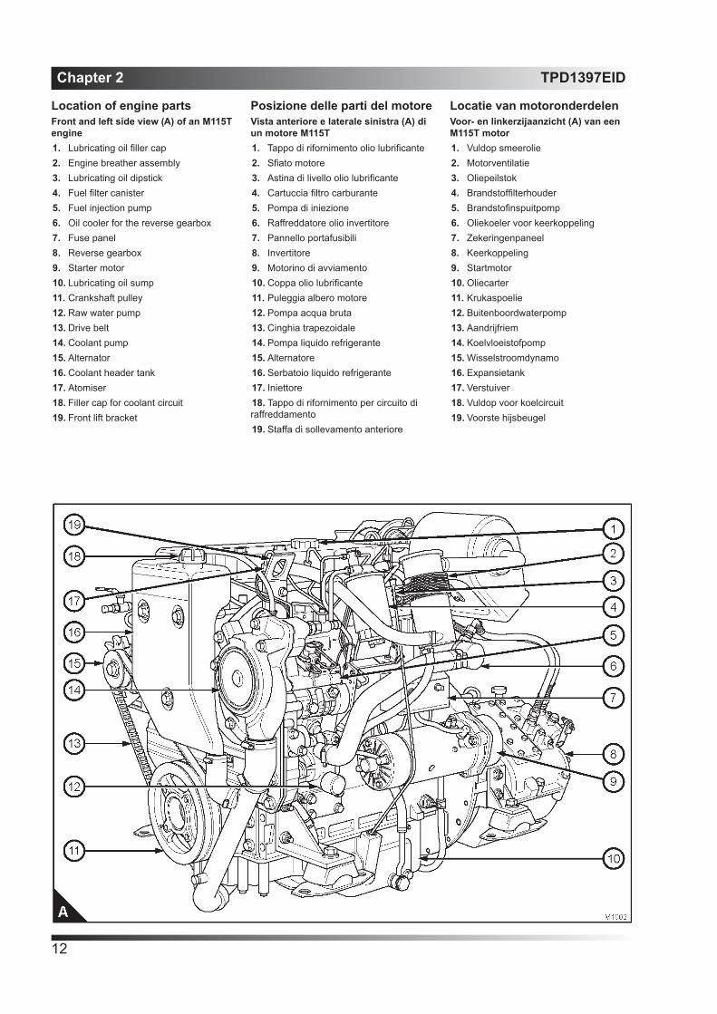
Location of engine partsFront and left side view (A) of an M115T engine1. Lubricating oil filler cap2. Engine breather assembly3. Lubricating oil dipstick4. Fuel filter canister5. Fuel injection pump6. Oil cooler for the reverse gearbox7. Fuse panel8. Reverse gearbox9. Starter motor10. Lubricating oil sump11. Crankshaft pulley12. Raw water pump13. Drive belt14. Coolant pump15. Alternator16. Coolant header tank17. Atomiser18. Filler cap for coolant circuit19. Front lift bracket
Posizione delle parti del motoreVista anteriore e laterale sinistra (A) di un motore M115T 1. Tappo di rifornimento olio lubrificante2. Sfiato motore3. Astina di livello olio lubrificante4. Cartuccia filtro carburante5. Pompa di iniezione6. Raffreddatore olio invertitore7. Pannello portafusibili8. Invertitore9. Motorino di avviamento10. Coppa olio lubrificante11. Puleggia albero motore12. Pompa acqua bruta13. Cinghia trapezoidale14. Pompa liquido refrigerante15. Alternatore16. Serbatoio liquido refrigerante17. Iniettore18. Tappo di rifornimento per circuito di raffreddamento19. Staffa di sollevamento anteriore
Locatie van motoronderdelenVoor- en linkerzijaanzicht (A) van een M115T motor1. Vuldop smeerolie2. Motorventilatie3. Oliepeilstok4. Brandstoffilterhouder5. Brandstofinspuitpomp6. Oliekoeler voor keerkoppeling7. Zekeringenpaneel8. Keerkoppeling9. Startmotor10. Oliecarter11. Krukaspoelie12. Buitenboordwaterpomp13. Aandrijfriem14. Koelvloeistofpomp15. Wisselstroomdynamo16. Expansietank17. Verstuiver18. Vuldop voor koelcircuit19. Voorste hijsbeugel

TPD1397EID Chapter 2
13
Rear and right side view (B) of an M115T engine20. Cooled exhaust manifold assembly21. Heat exchange22. Fuel lift pump23. Canister for the lubricating oil filter24. Lubricating oil cooler25. Oil drain plug for the reverse gearbox26. Drain pipe for the lubricating oil27. Oil dipstick for the reverse gearbox28. Thermostat29. Cooled exhaust outlet30. Turbocharger31. Air cleaner
Vista posteriore e laterale destra (B) di un motore M115T 20. Collettore di scarico raffreddato21. Scambiatore di calore22. Pompa di alimentazione23. Cartuccia per filtro olio lubrificante24. Radiatore olio lubrificante25. Tappo di scarico olio invertitore26. Tubazione di scarico olio lubrificante27. Astina di livello olio per invertitore28. Termostato29. Uscita di scarico raffreddata30. Turbocompressore31. Filtro aria
Achter- en rechterzijaanzicht (B) van een M115T motor20. Gekoeld uitlaatspruitstuk21. Warmtewisselaar22. Brandstofopvoerpomp23. Houder voor smeeroliefilter24. Smeeroliekoeler25. Olieaftapplug voor keerkoppeling26. Aftapplug smeerolie27. Oliekoeler voor keerkoppeling28. Thermostaat29. Gekoelde uitlaat30. Turbocompressor31. Luchtfilter

Chapter 2 TPD1397EID
14

TPD1397EID Chapter 3
15
Operation instructions
How to use the control panelThe main control panel for single and twin engine installations is shown in figure A. The switches are protected from the entry of water, but if the control panel is in an exposed location, it should be protected by a cover when not in use.Below is a description of the instruments and switches on the main panel.Panel illumination: the gauges are always illuminated, press the button (A1) to adjust the level of illumination.Engine electrical system / stop switch (A5), which has two positions:• OFF: Move the switch lever up to switch off the electrical system• ON: Move the switch lever down to energise the electrical system.Heat / start switch (A4), which is held up to energise the cold start aid (if one is fitted), or held down to energise the starter motor.Stop button (A6) press the button to stop the engine.Warning lamp (A2) to indicate that there is no electrical charge from the alternator.Voltmeter (A3) to indicate the condition of the batteries and of the alternator.
Istruzioni per l’uso
Come usare il quadro di comandoIl quadro di comando principale per le applicazioni con motore singolo o gemello è raffigurato in figura A. Gli interruttori sono protetti dall’ingresso di acqua, ma se il quadro di comando si trova in una posizione esposta, deve essere protetto da una copertura quando non viene usato.Segue una descrizione degli strumenti e interruttori sul quadro principale.Illuminazione del quadro: gli indicatori sono sempre illuminati, premere il pulsante (A1) per regolare il livello di illuminazione.Interruttore di arresto / impianto elettrico motore (A5), che ha due posizioni:• SPENTO: Spostare la leva verso l’alto per spegnere l’impianto elettrico.• ACCESO: Spostare la leva verso il basso per eccitare l’impianto elettrico.Interruttore di riscaldamento / avviamento (A4), che viene tenuto sollevato per attivare il coadiuvatore di avviamento (se in dotazione), o abbassato per eccitare il motorino di avviamento.Pulsante di arresto (A6) premere il pulsante per spegnere il motore.Spia (A2) per indicare che non vi è carica elettrica dall’alternatore.Voltometro (A3) per indicare lo stato delle batterie e dell’alternatore.
Instructies voor gebruik
Gebruiksaanwijzing van het bedieningspaneelIn afbeelding A wordt het hoofdbedieningspaneel voor installaties met één of twee motoren getoond. De schakelaars zijn waterdicht, maar als het bedieningspaneel op een open plek is aangebracht, moet het worden afgedekt wanneer het niet wordt gebruikt.Hieronder volgt een beschrijving van de instrumenten en schakelaars op het hoofdpaneel.Paneelverlichting: de meter zijn altijd verlicht; druk op knop (A1) om de verlichtingssterkte in te stellen.Elektrisch systeem motor / stopschakelaar (A5); deze heeft twee standen:• OFF (uit): Zet de schakelhendel omhoog om het elektrisch systeem uit te schakelen.• ON (aan): Zet de schakelhendel omlaag om het elektrisch systeem in te schakelen.Verwarmen / starten-schakelaar (A4); houd deze omhoog om de koudstarthulp te activeren (indien gemonteerd), of omlaag om de startmotor te bekrachtigen.Stop-knop (A6) druk op deze knop om de motor te stoppen.Waarschuwingslamp (A2) om aan te geven dat de wisselstroomdynamo niet bijlaadt.Voltmeter (A3) om de conditie van de accu’s en van de wisselstroomdynamo aan te geven.

Chapter 3 TPD1397EID
16
Warning lamp (A10) for high coolant temperatureGauge (A9) to indicate high coolant temperature.Tachometer (A12) to indicate the engine speed.The tachometer also has an hourmeter, this can be used to ensure that the engine is maintained at the correct intervals.Warning lamp (A8) for low lubricating oil pressure.Gauge (A7) to indicate the lubricating oil pressure of the engine.Warning lamp (A11) for water in the fuel. This will operate only if an optional device to find water in the fuel is fitted to the fuel pre-filter. If this device is fitted, the lamp will also be illuminated for approximately 10 seconds when the warning system operates.Audible warning device, which operates if the engine has low lubricating oil pressure or high coolant temperature. The audible warning device is situated behind the control panel.Caution: If the audible warning device operates, the warning light(s) on the relevant main panel will indicate the engine affected. Reduce the speed of the engine affected to idle and, if necessary, stop the engine see page 22. Find the fault, see section 6.
Spia (A10) dell’alta temperatura del liquido refrigeranteManometro (A9) per indicare l’alta temperatura del liquido refrigerante.Contagiri (A12) per indicare il regime motore. Il contagiri è anche dotato di contaore che può essere usato per fare in modo che la manutenzione del motore venga eseguita agli intervalli corretti.Spia (A8) di bassa pressione dell’olio lubrificante.Manometro (A7) per indicare la pressione dell’olio lubrificante del motore.Spia (A11) per indicare che vi è acqua nel combustibile. Questa spia funziona solo se il prefiltro del combustibile è stato dotato di dispositivo opzionale che rileva la presenza di acqua nel combustibile. Se questo dispositivo è montato, la spia rimane anche accesa per 10 secondi circa quando l’interruttore dell’impianto di allarme è attivato.Spia acustica, che entra in funzione se la pressione dell’olio lubrificante è bassa o se la temperatura del liquido refrigerante è alta. La spia acustica è situata dietro il quadro di comando.Attenzione: Se la spia acustica viene attivata, la spia o spie sul rispettivo quadro principale indicano il motore in oggetto. Portare al minimo il regime del motore in oggetto e, se necessario, arrestare il motore, vedere pag. 22. Ricercare il guasto, vedere sezione 6..
Waarschuwingslamp (A10) om aan te geven dat de koelvloeistoftemperatuur te hoog is.Meter (A9) om aan te geven dat de koelvloeistoftemperatuur te hoog is.Toerentalmeter (A12) om het motortoerental aan te geven. De toerentalmeter heeft tevens een urenmeter, die kan worden gebruikt bij de bepaling van de onderhoudsintervallen.Waarschuwingslamp (A8) om aan te geven dat de smeeroliedruk te laag is.Meter (A7) om de smeeroliedruk in de motor aan te geven.Waarschuwingslamp (A11) om aan te geven dat er water in de brandstof is gekomen. Dit lampje werkt uitsluitend wanneer tevens een sensor (optioneel) in de brandstofvoorfilter is gemonteerd. Is dit het geval, dan brandt dit lampje tevens gedurende ongeveer 10 seconden wanneer de schakelaar van het waarschuwingssysteem wordt ingeschakeld.Het akoestisch waarschuwingssignaal treedt in werking wanneer de oliedruk van de motor laag is of wanneer de koelvloeistoftemperatuur te hoog is. De zoemer is gemonteerd achter het bedieningspaneel.Voorzichtig: Wanneer het akoestisch waarschuwingssignaal in werking treedt, wordt via waarschuwingslampje(s) op het relevante hoofdpaneel aangegeven om welke motor het gaat. Verlaag het toerental van de motor naar stationair toerental en, indien nodig, stop de motor, zie pagina 22. Zoek op waar de storing vandaan komt; zie sectie 6.

TPD1397EID Chapter 3
17
Auxiliary control panelThe auxiliary control panel shown in figure A is used on craft which have an extra control point. The switches are protected from the entry of water, but if the control panel is in an exposed location, it should be protected by a cover when not in use.Below is a description of the instrument and switches on the auxiliary panel.Caution: If the audible warning device operates, the warning light(s) on the relevant main panel will indicate the engine affected. Reduce the speed of the engine affected to idle and, if necessary, stop the engine see page 22. Find the fault, see section 6.Audible warning device, which operates if the engine has low lubricating oil pressure or high coolant temperature.Engine electrical system / stop switch (A5), which has two positions:• OFF: Move the switch lever up to switch off the electrical system• ON: Move the switch lever down to energise the electrical system.Tachometer (A7) to indicate the engine speed.Heat / start switch (A4), which is held up to energise the cold start aid (if one is fitted), or held down to energise the starter motor.Stop button (A6) press the button to stop the engine.Warning lamp (A3) to indicate that there is no electrical charge from the alternator.Warning lamp (A2) for high coolant temperature.Warning lamp (A1) for low lubricating oil pressure.
Quadro di comando ausiliarioIl quadro di comando ausiliario indicato in figura A viene usato sulle imbarcazioni dotate di punto controllo extra. Gli interruttori sono riparati dall’ingresso di acqua, ma se il quadro si trova in posizione vulnerabile, proteggerlo con una copertura quando non è utilizzato.Segue una descrizione degli strumenti e degli interruttori sul quadro di comando ausiliario.Attenzione: Se la spia acustica viene attivata, la spia o spie sul rispettivo quadro principale indicheranno il motore in oggetto. Portare al minimo il regime del motore in oggetto e, se necessario, arrestare il motore, vedere pag. 22. Ricercare il guasto, vedere sezione 6.Spia acustica, che entra in funzione se la pressione dell’olio lubrificante è bassa o se la temperatura del liquido refrigerante è alta.Interruttore di arresto / impianto elettrico motore (A5), con due posizioni:• SPENTO: Spostare la leva verso l’alto per spegnere l’impianto elettrico.• ACCESO: Spostare la leva verso il basso per eccitare l’impianto elettrico.Contagiri (A7) per indicare il regime motore.Interruttore di riscaldamento / avviamento (A4), che viene tenuto sollevato per eccitare il coadiuvatore di avviamento (se in dotazione) o abbassato per eccitare il motorino di avviamento.Pulsante di arresto (A6) premere questo pulsante per spegnere il motore.Spia (A3) per indicare che l’alternatore non sta caricando.Spia (A2) dell’alta temperatura del liquido refrigerante.Spia (A1) della bassa pressione dell’olio lubrificante.
HulpbedieningspaneelHet hulpbedieningspaneel dat wordt getoond in afbeelding A, wordt gebruikt op vaartuigen met een extra bedieningslocatie. De schakelaars zijn waterdicht, maar als het bedieningspaneel op een open plek is aangebracht, moet het worden afgedekt wanneer het niet wordt gebruikt.Hieronder volgt een beschrijving van de instrumenten en schakelaars op het hulppaneel.Voorzichtig: Wanneer het akoestisch waarschuwingssignaal in werking treedt, wordt via waarschuwingslampje(s) op het relevante hoofdpaneel aangegeven om welke motor het gaat. Verlaag het toerental van de motor naar stationair toerental en, indien nodig, stop de motor, zie pagina 22. Zoek op waar de storing vandaan komt; zie sectie 6.Het akoestisch waarschuwingssignaal treedt in werking wanneer de oliedruk van de motor laag is of wanneer de koelvloeistoftemperatuur te hoog is.Elektrisch systeem motor / stopschakelaar (A5); deze heeft twee standen:• OFF (uit): Zet de schakelhendel omhoog om het elektrisch systeem uit te schakelen.• ON (aan): Zet de schakelhendel omlaag om het elektrisch systeem in te schakelen.Toerentalmeter (A7) om het motortoerental aan te geven.Verwarmen / starten-schakelaar (A4); houd deze omhoog om de koudstarthulp te activeren (indien gemonteerd), of omlaag om de startmotor te bekrachtigen.Stop-knop (A6) druk op deze knop om de motor te stoppen.Waarschuwingslamp (A3) om aan te geven dat de wisselstroomdynamo niet bijlaadt.Waarschuwingslamp (A2) om aan te geven dat de koelvloeistoftemperatuur te hoog is.Waarschuwingslamp (A1) om aan te geven dat de smeeroliedruk te laag is.

Chapter 3 TPD1397EID
18
Fuse panelCautions: • Always fit the correct fuse. Damage to the wiring loom may occur if a higher rated fuse is fitted.• Always find the cause of a fuse failure and correct the fault. If in doubt, consult an electrician at your nearest Perkins distributor.A wiring loom, which includes a fuse panel to protect the wiring from damage by a short circuit, has been fitted to your engine.The fuse panel (A) is situated above the starter motor, behind the cover marked “FUSES”, and is fitted with the fuses listed in the table. The fast fuse (A4) protects the alternator if the battery cables are connected to the wrong terminal. To renew fuses (A1, A2 and A3)Note: The fuses are protected by a waterproof cover.1. Release the two nuts and remove the cover.2. Pull the affected fuse out of its holder.3. To remove the fast fuse (A4), release the two nuts that fasten it to the fuse panel and remove the fuse.
Pannello portafusibiliAttenzione:• Montare sempre il corretto fusibile. Se viene montato un fusibile di potenza superiore il cablaggio potrebbe subire danni.• Scoprire sempre la causa di un fusibile bruciato e correggere il guasto. In caso di dubbi, rivolgersi ad un elettricista presso il distributore Perkins di zona.Sul motore è stato montato un cablaggio di tipo migliorato, contenente un pannello portafusibili, che lo protegge dai danni causati da un cortocircuito.Il pannello portafusibili (A) è situato sopra il motorino di avviamento, dietro il coperchio marcato “FUSIBILI”, e contiene i fusibili elencati in tabella. Il fusibile ad azione rapida (A4) protegge l’alternatore se i cavi della batteria vengono collegati al morsetto sbagliato. Sostituzione dei fusibili (A1, A2 e A3)Nota: I fusibili sono protetti da un coperchio impermeabile.1. Allentare i due dadi e togliere il coperchio.2. Estrarre il fusibile bruciato dal portafusibile.3. Per estrarre il fusibile ad azione rapida (A4), allentare i due dadi che lo fissano sul pannello portafusibili e quindi toglierlo.
ZekeringenpaneelVoorzichtig:• Breng altijd de juiste zekering aan. Wanneer er een zwaardere zekering wordt aangebracht, kan er schade aan de kabelboom ontstaan.• Zoek altijd de oorzaak voor het doorbranden van een zekering en verhelp de betreffende storing. Raadpleeg bij twijfel een elektriciën bij de Perkins dealer bij u in de buurt.Uw motor is voorzien van een type kabelboom waarin tevens een zekeringenpaneel is opgenomen, ter voorkoming van schade aan de bedrading t.g.v. kortsluiting.Dit zekeringenpaneel (A) bevindt zich boven de startmotor, achter de deksel met het opschrift “ZEKERINGEN” en bevat de zekeringen zoals vermeld in onderstaande tabel. De snelle zekering (A4) beschermt de wisselstroomdynamo tegen foutief aansluiten van de accukabels. Zekeringen (A1, A2 en A3) vervangenLet op: De zekeringen worden beschermd door een spatwaterdicht deksel.1. Draai de twee moeren los en verwijder het deksel.2. Trek de betreffende zekering uit de houder.3. Om de snelle zekering (A4) te kunnen verwijderen, dient u de twee moeren los te draaien waarmee de zekering is vastgezet aan het zekeringenpaneel; verwijder daarna de zekering.
Fuse description / Descrizione fusibile/Omschrijving zekering
Fuse rating (amperes) / Valore nominale fusibile (ampere)/Toelaatbare belasting
zekering (A)
Part number/Parte numero/
OnderdeelnummerStart circuit (A1) / Circuito di avviamento (A1)/Startmotorcircuit (A1) 40 33860
Panel circuitl (A2)/ Circuito 1 quadro (A2)/Paneelcircuit (A2) 10 33858
Negative line protection (A3) / Protezione linea negativa (A2)/Massabeveiliging (A2) 10 33859
Fast fuse (A4) / Fusibile ad azione rapida (A4)/Snelle zekering (A4) 85 40561

TPD1397EID Chapter 3
19
4. To remove the fast fuse (A4, page 18), release the two nuts that fasten it to the fuse panel and remove the fuse.5. To fit a fuse, push the fuse into its holder. The fast fuse is retained by two nuts.Fit the cover and tighten the two nuts.New fuses can be obtained from your Perkins distributor. The part numbers for the fuses are listed in the table below.It is recommended that an extra set of fuses is included in the supplementary tool kit and retained on-boardStart retard mechanismThe fuel injection pump has an electrical start retard mechanism that retards the injection timing from the fully advanced position, for starting, to the normal operating condition as the engine warms. The start retard mechanism begins to operate at a coolant temperature of 55OC (131OF). A green lamp can be seen through a hole in the cover of the fuse panel to indicate that the start retard is in operation.
4. Per montare un fusibile, infilarlo nel portafusibile. Il fusibile ad azione rapida è fissato da due dadi.5. Montare il coperchio e serrare i due dadi.I nuovi fusibili possono essere reperiti presso il concessionario Perkins. I numeri di parte dei fusibili sono elencati nella tabella qui sotto.Si raccomanda di includere una serie extra di fusibili nel kit di attrezzi supplementari e di conservarla a bordoMeccanismo di ritardo dell’avviamentoLa pompa di iniezione è dotata di meccanismo di ritardo dell’avviamento che ritarda la fasatura dell’iniezione dalla posizione completamente anticipata per l’avviamento, a quella d’esercizio normale non appena il motore si riscalda. Il meccanismo di ritardo dell’avviamento inizia a funzionare quando la temperatura del liquido refrigerante raggiunge i 55OC (131OF). È possibile vedere attraverso un foro nel coperchio del pannello portafusibili una spia verde che indica che il dispositivo di ritardo dell’avviamento sta funzionando.
4. Druk de zekering in de houder om deze aan te brengen. De snelle zekering wordt vastgezet met twee moeren.5. Breng de beschermkap aan en haal de twee moeren aan.Nieuwe zekeringen zijn verkrijgbaar bij uw Perkins dealer. Zie onderstaande tabel voor de onderdeelnummers van de zekeringen.Geadviseerd wordt om een reserveset zekeringen mee aan boort te nemen in de gereedschapkist.StartvertragingsmechanismeDe brandstofinspuitpomp is voorzien van een elektrisch startvertragingsmechanisme dat de inspuittijd van volledig vervroegd bij het starten geleidelijk aan weer terugzet naar de normale stand tijdens het opwarmen van de motor. Het startvertragingsmechanisme begint te werken bij een koelvloeistoftemperatuur van 55OC (131OF). Een groene lamp, te zien via een opening in het zekeringenpaneel, licht op om aan te geven dat de startvertraging in werking is.

Chapter 3 TPD1397EID
20
How to start the engineUse only this procedure to start the engine; it has been designed to protect the engine and the environment.Several factors affect engine start, for example:• The power of the batteries• The performance of the starter motor• The viscosity of the lubricating oil• The installation of a cold start system.Diesel engines need a cold starting aid if they are to start in extremely cold conditions. These engines can be fitted with a fuelled starting aid. This electrically operated device ignites a specific amount of diesel fuel in the induction manifold. The use of a cold start aid is only necessary in ambient temperatures colder than -10OC (14OF). If it is necessary to operate engines in these conditions, a cold start kit should be fitted.Before the engine is started the operator should understand fully the controls and their use.Preparations for an engine start1. Ensure that there is more than enough fuel in the tank for the voyage.2. Ensure that the fuel supply control (if fitted) is in the open position.3. Check that the seacock strainer is clean.4. Open the seacock.5. Check the amount of coolant in the header tank.6. Check the amount of lubricating oil in the sump, and in the reverse gearbox.7. Ensure that the control lever for the reverse gearbox is in the neutral position.Caution: If the engine has not run for several weekssee “Caution” on page 72.
Come avviare il motoreSeguire esclusivamente questa procedura per avviare il motore, dato che è stata studiata per proteggere il motore e l’ambiente.Diversi fattori influenzano l’avviamento del motore, ad esempio:• La carica delle batterie• Il rendimento del motorino di avviamento• La viscosità dell’olio lubrificante• L’installazione di un impianto di avviamento a freddoI motori diesel hanno bisogno di un dispositivo di avviamento a freddo se devono essere avviati in condizioni molto fredde. Questi motori possono essere dotati di termoavviatore. Questo dispositivo ad azionamento elettrico innesca una quantità dosata di gasolio nel collettore di aspirazione. L’impiego del coadiuvatore di avviamento è necessario solo a temperature ambiente inferiori a -10OC . Se è necessario far funzionare i motori in queste condizioni, montare un coadiuvatore di avviamento.Prima di avviare il motore, l’operatore deve comprendere a fondo la funzione dei comandi e il loro impiego.Preparativi per l’avviamento del motore1. Controllare che vi sia più combustibile di quanto sia necessario per il viaggio.2. Controllare che il comando di mandata del combustibile (se in dotazione) si trovi su “aperto”.3. Controllare che il filtro della presa dell’acqua del mare sia pulito.4. Aprire la presa dell’acqua di mare.5. Controllare la quantità di liquido refrigerante nel serbatoio.6. Controllare la quantità di olio lubrificante nella coppa e nell’invertitore.7. Controllare che la leva di comando dell’invertitore sia in folle.Attenzione: Se il motore non ha funzionato per varie settimane, vedere “Attenzione” a pag. 72.
De motor startenVolg uitsluitend de navolgende procedure voor het starten van de motor; deze is bedoeld om de motor en het milieu te beschermen.Diverse factoren zijn van invloed op het starten van de motor. Bijvoorbeeld:• vermogen van de accu’s;• vermogen van de startmotor;• viscositeit van de motorolie;• het al dan niet voorhanden zijn van een koudstartsysteem.Dieselmotoren hebben een koudstartsysteem nodig voor het starten onder zeer koude omstandigheden. Deze motoren kunnen worden uitgerust met een starthulp (op brandstof). Deze elektrisch geregelde starthulp ontsteekt een kleine hoeveelheid diesel in het inlaatspruitstuk. Het gebruik van een koudstartsysteem is uitsluitend noodzakelijk bij omgevingstemperaturen lager dan -10OC (14OF). Wanneer de motor gebruikt moet worden onder deze omstandigheden, moet een koudstartsysteem worden aangebracht.Voordat de motor wordt gestart, moet degene die de motor bedient goed op de hoogte zijn van de controles en van de betreffende procedures.Voorbereiding voor het starten1. Zorg dat er meer dan voldoende brandstof in de tank aanwezig is voor de reis.2. Zorg ervoor dat de brandstofkraan (indien aanwezig) open staat.3. Zorg ervoor dat het filter van de buitenboordkraan schoon is.4. Open de buitenboordkraan.5. Controleer het koelvloeistofpeil in het expansiereservoir.6. Controleer het oliepeil in het oliecarter en in de keerkoppeling.7. Zorg ervoor dat de brandstofkraan (indien aanwezig) open staat.Voorzichtig: Wanneer de motor langere tijd heeft stilgestaan, zie “Voorzicht” op pagina 72.

TPD1397EID Chapter 3
21
How to start a cold engine in cold conditionsCaution: Ether type fuels must not be used.Note: Use this method when the ambient temperature is colder than -10OC (14OF) and the cold start kit has been fitted.1. Switch on the electrical system.2. Check that the reverse gearbox is in neutral. Adjust the engine speed control to the minimum speed position.3. Hold the lever of the heat/start switch (A4, page 15) in the up position for 15 seconds. Hold the lever of the heat/start switch in the down position to engage the starter motor. When the engines starts, release the lever. Adjust the engine speed control to give an even idle.4. Check that water comes out of the end of the exhaust pipe or out of the separate discharge outlet.5. If the engine does not start in 15 seconds, allow the starter motor to cool for 30 seconds. When the engine has started, adjust the engine speed control to get an even idle speed. Check that water comes out of the end of the exhaust pipe or out of the separate discharge outlet.Always ensure that the engine and starter motor are stationary before the starter motor is engaged again.How to start a warm engine, or if the ambient temperature is hotter than -10OC (14OF).1. Switch on the electrical system.2. Check that the reverse gearbox is in neutral. Adjust the engine speed control to the minimum speed position.3. Hold the start switch down to engage the starter motor. When the engine starts, adjust the engine speed control to give an even idle speed. Check that water comes out of the end of the exhaust pipe or out of the separate discharge outlet.3. Always ensure that the engine and starter motor are stationary before the starter motor is engaged again.
Avviamento di un motore freddo in ambienti freddiAttenzione: Non usare combustibili di tipo ad etere.Nota: Usare questo metodo quando la temperatura ambiente è inferiore a -10OC ed è stato montato un kit di avviamento a freddo.1. Accendere l’impianto elettrico.2. Controllare che l’invertitore sia in folle. Regolare la leva di accelerazione sul minimo più basso.3. Tenere sollevata per 15 secondi la leva dell’interruttore di accensione / riscaldamento (A4). Tenere abbassata la leva dell’interruttore di accensione / riscaldamento per innestare il motorino di avviamento. Quando il motore parte, rilasciare la leva. Regolare la leva di accelerazione per ottenere un minimo uniforme.4. Controllare che l’acqua esca dall’estremità del tubo di scarico o dall’uscita di scarico a parte.5. Se in motore non parte entro 15 secondi, lasciare che il motorino di avviamento si raffreddi per 30 secondi. Quando il motore è partito, regolare il comando del regime motore per ottenere un minimo regolare. Controllare che l’acqua esca dall’estremità del tubo di scarico o dall’uscita di scarico a parte.Controllare sempre che il motore e il motorino di avviamento siano fermi prima di azionare nuovamente il motorino.Come avviare un motore caldo, oppure se la temperatura ambiente è superiore a -10OC.1. Accendere l’impianto elettrico.2. Controllare che l’invertitore sia in folle. Regolare la leva di accelerazione sul minimo più basso.3. Tenere abbassato l’interruttore di accensione per innestare il motorino di avviamento. Quando il motore parte, regolare la leva di accelerazione per ottenere un minimo uniforme. Controllare che l’acqua esca dall’estremità del tubo di scarico o dall’uscita di scarico a parte.Controllare sempre che il motore e il motorino di avviamento siano fermi prima di azionare nuovamente il motorino.
De motor starten in koude omstandighedenVoorzichtig: Geen vluchtige brandstoffen gebruiken.Let op: Volg onderstaande procedure wanneer de omgevingstemperatuur lager is dan -10OC (14OF) en een koudstartsysteem is aangebracht.1. Het elektrische systeem inschakelen.2. Controleren of de keerkoppeling in de vrij staat. De toerenregeling van de motor op minimum zetten.3. Houd de hendel van de verwarmen/starten-schakelaar (A4) gedurende 15 sec. omhoog. Houd de hendel van de verwarmen/starten-schakelaar omlaag om de startmotor te bekrachtigen. Laat de hendel los zodra de motor start. Stel de toerenregelaar vervolgens in op een gelijkmatig stationair toerental.4. Controleer of er water uit de uitlaatpijp of de daartoe bestemde afvoer komt.5. Als de motor niet binnen 15 seconden start, de startmotor eerst 30 sec. laten afkoelen. Wanneer de motor is gestart, de toerentalregeling zodanig instellen dat een gelijkmatig stationair toerental wordt verkregen. Controleer of er water uit de uitlaatpijp of de daartoe bestemde afvoer komt.Zorg er altijd voor dat de motor en de startmotor stilstaan, voordat de startmotor opnieuw in werking wordt gesteld.Het starten van een warme motor resp. het starten van een motor bij een omgevingstemperatuur hoger dan -10OC (14OF).1. Het elektrische systeem inschakelen.2. Controleren of de keerkoppeling in de vrij staat. De toerenregeling van de motor op minimum zetten.3. Houd de startschakelaar omlaag om de startmotor te bekrachtigen. Zodra de motor start, de toerenregeling instellen op een gelijkmatig stationair toerental. Controleer of er water uit de uitlaatpijp of de daartoe bestemde afvoer komt.Zorg er altijd voor dat de motor en de startmotor stilstaan, voordat de startmotor opnieuw in werking wordt gesteld.

Chapter 3 TPD1397EID
22
How to stop the engine1. Adjust the engine speed control to the minimum speed position. Ensure that the control lever for the reverse gearbox is in the neutral position. If the engine has operated at high load for a long period of time, allow the engine to cool for one to two minutes.2. Press the stop button (A6 page 15) (A6 page 17) until the engine stops. Release the stop switch or rotate the switch to the off position.
Adjustment of engine speed rangeThe idle or maximum speed settings must not be changed by the engine operator, because this can damage the engine or the transmission. The warranty of the engine can be affected if the seals on the fuel injection pump are broken during the warranty period by a person who is not approved by Perkins.
Running-inA gradual running-in of a new engine is not necessary. Prolonged operation at light loads during the early life of the engine can cause lubricating oil to enter the exhaust system. Maximum load can be applied to a new engine as soon as the engine is put into service and the coolant temperature has reached a minimum of 60OC (140OF).Cautions:• The engine will benefit if the load is applied as soon as possible after the engine is put into service.• Do not operate the engine at high speeds without a load.• Do not overload the engine.
Angle of tiltFor yachts with auxiliary engines, it may be necessary to use the engine during operation against the wind. In these conditions, an angle of tilt (port or starboard) up to 25O continuous operation or 35O intermitent operation is permissible.
Come spegnere il motore1. Regolare la leva di accelerazione sul minimo più basso. Controllare che la leva di comando dell’invertitore sia in folle. Se il motore ha funzionato a un carico elevato per un periodo lungo, lasciare che si raffreddi per uno o due minuti.2. Premere il pulsante di arresto (A6 pag. 15) (A6 pag. 17) fino a quando il motore si spegne. Rilasciare l’interruttore di arresto oppure ruotarlo sulla posizione spenta.
Registrazione del regime del motoreLa registrazione dei regimi minimo e massimo non deve essere modificata dall’operatore dato che si potrebbero arrecare danni a motore o trasmissione. La garanzia del motore decade se i sigilli sulla pompa di iniezione vengono rotti, durante il periodo di decorrenza della garanzia, da persone non autorizzate dalla Perkins.
RodaggioNon è necessario un rodaggio graduale di un motore nuovo. Un funzionamento prolungato a carico leggero durante il periodo iniziale di funzionamento del motore può causare l’ingresso di olio lubrificante nell’impianto di scarico. Il carico massimo può essere applicato su un motore nuovo non appena il motore viene messo in servizio e la temperatura del liquido refrigerante ha raggiunto almeno i 60OC.Attenzione:• Sarà meglio per il motore se il carico viene applicato immediatamente dopo l’avviamento iniziale.• Non far funzionare il motore a regimi elevati a vuoto.• Non sovraccaricare il motore.
Angolo di inclinazionePer imbarcazioni con motori ausiliari, può essere necessario usare il motore durante la navigazione contro vento. In queste condizioni, è permesso un angolo di inclinazione (verso sinistro o verso dritta) di fino a 25o per il funzionamento continuo o di 35o per il funzionamento intermittente.
De motor stoppen1. De toerenregeling van de motor op minimum zetten. Zorg ervoor dat de brandstofkraan (indien aanwezig) open staat. Is de motor gedurende langere tijd zwaar belast, laat deze dan een of twee minuten afkoelen.2. Druk op de stoptoets (A6 pagina 15) (A6 pagina 17) tot de motor stopt. Laat de stopschakelaar los of draai de schakelaar naar de uit-stand.
Instellen van toerenbereik van de motorHet ingestelde stationaire toerental en het maximale toerental mogen niet door de bediener van de motor worden gewijzigd, omdat dit tot beschadiging van de motor of de transmissie kan leiden. Het verbreken van de verzegeling van de brandstofinspuitpomp door een niet door Perkins geautoriseerde persoon kan gevolgen hebben voor de garantie op de motor.
InlopenHet geleidelijk aan laten inlopen van een nieuwe motor is niet nodig. Langdurig bedrijf bij lichte belasting kan er bij een nieuwe motor toe leiden dat er motorolie in het uitlaatsysteem komt. Een nieuwe motor kan direct maximaal worden belast zodra de koelvloeistof een temperatuur van minimaal 60OC (140OF) heeft bereikt.Voorzichtig:• Het is beter voor de motor om deze na ingebruikname zo spoedig mogelijk te belasten.• De motor niet onbelast op hoge toeren laten draaien.• De motor niet overbelasten.
KantelhoekVoor jachten met hulpmotoren kan het nodig zijn om de motor tegen de wind in te gebruiken. Onder deze condities is een kantelhoek (aan bak- of stuurboord) van max. 25O continu resp. van 35O kortstondig toegestaan.

TPD1397EID Chapter 3
23
Free rotation of the propeller shaft or “trailing”The propeller shaft of both the Newage PRM 500D and the ZF-Hurth HBW 450A reverse gearboxes can be allowed to turn continuously with the control lever in the neutral position.The recommendations of the manufacturer of the reverse gearbox must be followed.
Operation of the lever for gear selection Newage PRM 500D reverse gearbox (A)For same-as-crankshaft rotation, move the lever to the position (A1).To put the reverse gearbox into neutral, move the lever to the centre position (A2).For opposite-to-crankshaft rotation, move the lever to the position (A3).ZF-Hurth HBW 450A (B)For same-as-crankshaft rotation, move the lever to the position (B3).To put the reverse gearbox into neutral, move the lever to the position (B2).For opposite-to-crankshaft rotation, move the lever to the position (B1).
Rotazione libera dell’albero portaelica o di “uscita”L’albero portaelica degli invertitori Newage PRM 500D e ZF-Hurth HBW 450A può essere fatto funzionare continuamente con la leva di comando in folle.Seguire alla lettera le raccomandazioni del fabbricante dell’invertitore.
Funzionamento della leva di selezione marceInvertitore Newage PRM 500D (A)Per ottenere una rotazione analoga a quella dell’albero motore, spostare la leva sulla posizione (A1).Per mettere in folle l’invertitore, spostare la leva sulla posizione centrale (A2).Per una rotazione opposta a quella dell’albero motore, spostare la leva sulla posizione (A3).ZF-Hurth HBW 450A (B)Per una rotazione analoga a quella dell’albero motore, spostare la leva sulla posizione (B3).Per mettere in folle l’invertitore, spostare la leva sulla posizione (B2).Per una rotazione opposta a quella dell’albero motore, spostare la leva sulla posizione (B1).
Vrije rotatie van de schroefas of “meelopen”De schroefas van de Newage PRM 500D resp. de ZF-Hurth HBW 450A keerkoppeling mag continu meedraaien met de bedieningshendel “in de vrij”.De aanbevelingen van de fabrikant van de keerkoppeling moeten worden opgevolgd.
Gebruik van de schakelhendelNewage PRM 500D keerkoppeling (A)Om de keerkoppeling in dezelfde richting te laten draaien als de krukas, de hendel naar stand (A1) bewegen.Om de keerkoppeling in vrijloopstand te plaatsen, de hendel in de middenstand (A2) zetten.Om de keerkoppeling tegen de draairichting van de krukas in te laten draaien, de hendel naar stand (A3) bewegen.ZF-Hurth HBW 450A (B)Om de keerkoppeling in dezelfde richting te laten draaien als de krukas, de hendel naar stand (B3) bewegen.Om de keerkoppeling in vrijloopstand te plaatsen, de hendel in stand (B2) zetten.Om de keerkoppeling tegen de draairichting van de krukas in te laten draaien, de hendel naar stand (B1) bewegen.

Chapter 3 TPD1397EID
24
Emergency proceduresIf the engine stops1. Check that the fuel supply valve (if fitted) is in the open position.2. Check the fuel pre-filter (if fitted) and the fuel filters for water. If a warning light (A5 page 15) for water in the fuel is fitted, and it is illuminated, water has entered the pre-filter. Water must be removed before the engine is operated. Drain any water found and fit new filters.3. Check the amount of fuel in the tank. If the engine has run until the tank is empty, there may be dirt or air in the fuel pipes. Change the fuel filter, see section 4. Fill the tank. Eliminate air from the system, see section 4.4. Start the engine again. If the engine still will not start, check that the cables and contacts of the stop solenoid are in good condition.If there is a reduction in engine speed or a loss of power1. Check that the propeller is free of debris.2. Check that the induction system is not restricted and that the engine compartment has a good supply of air.3. Check that the fuel pre-filter or the fuel filter elements are not restricted or contaminated by water. If a warning light (A5 page 15) for water in the fuel is fitted, and it is illuminated, water has entered the pre-filter. Water must be removed before the engine is operated. Drain any water found and fit new filters.If the warning lamp / audible warning for high coolant temperature operatesWarning! Do not remove the filler cap while the engine is still hot and the system is under pressure, because dangerous hot coolant can be discharged.1. Reduce the engine speed to idle. Stop the engine if there is a leakage of steam or coolant from the engine.2. Check that the coolant level is correct after the engine has cooled.3. Check the seacock and strainer to ensure that there is not a restriction to the supply of water to the cooling system.4. Check the raw water pump operation. Check the impeller see page 36.Note: Coolant leakage can be stopped temporarily with adhesive tape, hose and hose clips.
Procedure di emergenzaSe il motore si ferma1. Controllare che la valvola di alimentazione del combustibile (se in dotazione) sia aperta.2. Controllare che il prefiltro del combus-tibile (se montato) e i filtri del combustibile non contengano acqua. Se la spia (A5 pag. 15) dell’acqua nel combustibile è montata e si è accesa, significa che l’acqua è penetrata nel prefiltro. Spurgare l’acqua prima di far funzionare il motore. Far scolare l’acqua e montare dei nuovi filtri.3. Controllare la quantità di combustibile nel serbatoio. Se il motore ha funzionato fino allo svuotamento del serbatoio, è possibile che le tubazioni di alimentazione contengano sporcizia o aria. Sostituire il filtro del combustibile, vedere sezione 4. Riempire il serbatoio. Spurgare l’aria dall’impianto, vedere sezione 4.4. Avviare nuovamente il motore. Se il motore continua a non partire, controllare che i cavi e i contatti del solenoide di arresto siano in buono stato.Se vi è una riduzione del regime motore o una perdita di potenza1. Controllare che l’albero portaelica sia privo di detriti.2. Controllare che l’impianto di aspirazione non sia intasato e che il vano motore abbia una buona alimentazione di aria.3. Controllare che gli elementi del prefiltro e del filtro del combustibile non siano intasati e non contengano acqua. Se la spia (A5 pag. 15) dell’acqua nel combustibile è montata e si è accesa, significa che l’acqua è penetrata nel prefiltro. Spurgare l’acqua prima di far funzionare il motore. Far scolare l’acqua e montare dei nuovi filtri.Se la spia luminosa/acustica dell’alta temperatura del liquido refrigerante funzionaPericolo! Non togliere il tappo del bocchettone di rifornimento quando il motore è ancora caldo e l’impianto è sotto pressione, dato che si potrebbe avere la fuoriuscita di liquido refrigerante bollente.1. Ridurre il regime motore al minimo. Spegnere il motore se presenta una perdita di vapore o di liquido refrigerante.2. Controllare che il livello del liquido refrigerante sia corretto dopo aver lasciato raffreddare il motore.3. Controllare la presa dell’acqua del mare e il filtro per accertarsi che non vi siano intasamenti sull’alimentazione di acqua diretta all’impianto di raffreddamento.4. Controllare che la pompa dell’acqua bruta funzioni. Controllare la girante, vedere pag. 36.Nota: Le perdite di liquido refrigerante possono essere riparate temporaneamente con nastro adesivo, flessibili e fascette..
Procedures in noodgevalAls de motor stopt1. Controleer of de brandstoftoevoerkraan (indien aanwezig) open staat.2. Controleer of water in het brandstofvoorfilter (indien aanwezig) resp. de brandstoffilters is binnengedrongen. Wanneer een waarschuwingslamp (A5 pagina 15) voor water in de brandstof is gemonteerd en dit brandt, dan is water in het voorfilter binnengedrongen. Het water moet worden verwijderd voordat de motor in werking wordt gesteld. Tap het water af en monteer nieuwe filters.3. Controleer het brandstofniveau in de tank. Als de motor heeft gedraaid totdat de tank leeg is, kan er vuil of lucht in de brandstofleidingen zitten. Het brandstoffilter vervangen, zie sectie 4. De tank vullen. Het systeem ontluchten, zie sectie 4.4. De motor opnieuw starten. Als de motor nog steeds niet wil starten, controleer dan of de kabels en aansluitingen van de stopsolenoïde van de brandstofpomp in goede conditie zijn.Als het toerental afneemt of de motor vermogen verliest1. Controleer of de schroef vrij kan draaien (geen rommel, etc.).2. Controleer of het inlaatsysteem niet is verstopt en of er voldoende lucht in het motorcompartiment is.3. Controleer of de het brandstofvoorfilter of de overige brandstoffilters niet geblok-keerd zijn of dat water daarin is binnen-gedrongen. Wanneer een waarschuwings-lamp (A5 pagina 15) voor water in de brandstof is gemonteerd en dit brandt, dan is water in het voorfilter binnengedrongen. Het water moet worden verwijderd voordat de motor in werking wordt gesteld. Tap het water af en monteer nieuwe filters.Als de waarschuwingslamp / akoestisch waarschuwingssignaal voor te hoge koelvloeistoftemperatuur in werking treedtWaarschuwing! De vuldop niet verwijderen zolang de motor heet is en het systeem onder druk staat, omdat gevaarlijke, hete koelvloeistof naar buiten kan spuiten.1. Het motortoerental terugstellen naar stationair. De motor stoppen als stoom of koelvloeistof uit de motor komt.2. Controleer of het koelvloeistofpeil correct is, nadat de motor is afgekoeld.3. Controleer de buitenboordkraan en het waterfilter om er zeker van te zijn dat er voldoende water naar het koelsysteem stroomt..

TPD1397EID Chapter 3
25
If a high-pressure fuel pipe is broken or has a crackWarning! Ensure that fuel does not spray onto the skin. Stop the engine if there is a leakage of high-pressure fuel.1. Stop the engine.2. Remove the broken pipe from the engine.3. Connect the end of the pipe that is not broken to the fuel injection pump. Put the broken end of the pipe into a suitable container.4. Operate the engine at a reduced speed on the remainder of the cylinders. Empty the container at regular intervals.If leakage occurs from a low pressure fuel pipeTemporarily stop the leak with a hose and hose clips.If leakage of lubricating oil occurs:1. Stop the engine immediately and try to find the cause.2. If the main flow can be reduced, put a suitable container under the leakage point.3. Fill the engine with new lubricating oil at the same rate as the loss of oil and frequently check the lubricating oil pressure.
Se una tubazione del combustibile ad alta pressione si è rotta o si è tagliata:Pericolo! Evitare il contatto del combustibile con la pelle. Spegnere il motore se vi è una perdita di combustibile ad alta pressione.1. Spegnere il motore.2. Scollegare la tubazione rotta dal motore.3. Collegare il capo della tubazione non danneggiato alla pompa di iniezione. Infilare il capo rotto della tubazione in un contenitore adatto.4. Far funzionare il motore a regime ridotto con gli altri tre cilindri. Svuotare il contenitore ad intervalli regolari.Se si verifica una perdita da una tubazione di alimentazione a bassa pressioneRiparare temporaneamente la perdita con un flessibile e delle fascette.Se si verifica una perdita di olio lubrificante1. Spegnere immediatamente il motore e cercare di scoprire la causa.2. Se la portata principale può essere ridotta, infilare un contenitore adatto sotto il punto che perde.3. Riempire il motore con olio lubrificante pulito in quantità pari alla perdita e controllare frequentemente la pressione dell’olio lubrificante.
4. Controleer de werking van de buitenboordwaterpomp. Controleer de rotor, zie pagina 36.Let op: Lekkage van koelvloeistof kan gewoonlijk tijdelijk worden afgedicht met behulp van tape, een slang en slangklemmen. Als een hoge-drukbrandstofleiding gebroken of gescheurd isWaarschuwing! Let erop dat geen brandstof op de huid sproeit. Stop de motor indien ergens brandstof onder hoge druk weglekt.1. Zet de motor af.2. De defecte persleiding van de motor verwijderen.3. Het uiteinde van de persleiding dat niet defect is op de brandstofinspuitpomp aansluiten. Het defecte uiteinde in een geschikt reservoir plaatsen.4. De motor op een laag toerental op de resterende cilinders laten draaien. Het reservoir regelmatig leegmaken.Bij lekkage uit een lage-drukbrandstofleidingHet lek tijdelijk afdichten met een slang en slangklemmen.Bij lekkage van motorolie1. De motor onmiddellijk stopzetten en de oorzaak opsporen.2. Indien de hoofdstroom kan worden gereduceerd, een daartoe geschikt reservoir onder het lek plaatsen.3. De motor vullen met verse motorolie met dezelfde snelheid waarmee het wegstroomt en de oliedruk regelmatig controleren.

Chapter 3 TPD1397EID
26

TPD1397EID Chapter 4
27
Preventive maintenancePreventive maintenance periodsThese preventive maintenance periods apply to average conditions of operation. Check the periods given by the manufacturer of the boat in which the engine is installed. If necessary, use the shorter periods. When the operation of the engine must conform to the local regulations these periods and procedures may need to be adapted to ensure correct operation of the engine.It is good preventive maintenance to check for leakage and loose fasteners at each service.These maintenance periods apply only to engines that are operated with fuel and lubricating oil which conform to the specifications given in this handbook.Use the procedures in this section to maintain your engine in accordance with the preventive maintenance schedule see page 28.
Manutenzione preventivaIntervalli della manutenzione preventivaGli intervalli di manutenzione preventiva sono validi per condizioni d’esercizio normali. Controllare gli intervalli raccomandati dal costruttore dell’imbarcazione su cui è installato il motore. Se necessario, abbreviare gli intervalli. Quando l’uso del motore deve essere conforme alle norme locali vigenti, tali intervalli e procedure devono essere adattati per garantire il corretto funzionamento del motore.È buona norma di manutenzione preventiva controllare, in occasione di ogni tagliando, che non vi siano perdite e che la bulloneria non si sia allentata.Gli intervalli di manutenzione sono validi solo per i motori usati con combustibile e olio lubrificante conformi alle caratteristiche tecniche riportate in questo manuale.Usare le procedure contenute in questa sezione per eseguire la manutenzione del motore in base ai programmi di manutenzione preventiva, vedere pag. 28.
Preventief onderhoudPreventief onderhoud, intervallenDe volgende intervallen voor preventief onderhoud gelden bij normaal gebruik van de motor. Controleer de intervallen die worden aangegeven door de fabrikant van de boot waarin de motor is geplaatst. Houd, indien nodig, kortere intervallen aan. Indien de werking van de motor moet voldoen aan bepaalde ter plekke geldende richtlijnen, dan kan het nodig zijn de intervallen en procedures aan te passen om zodoende een correcte werking van de motor te verkrijgen.In het kader van preventief onderhoud dient bij elke onderhoudsbeurt te worden gecontroleerd op lekkage en losse bevestigingen.Deze onderhoudsintervallen zijn uitsluitend van toepassing op motoren waarin brandstof en motorolie worden toegepast die voldoen aan de in dit handboek vermelde specificaties.Gebruik de procedures in deze sectie om uw motor te onderhouden in overeenstemming met het preventieve onderhoudsschema, zie pagina 28.

Chapter 4 TPD1397EID
28
SchedulesThe schedules which follow must be applied at the interval (hours or months) which occur first.A First service at 25/50 hours D Every 500 hours or 12 months G Non-scheduled maintenanceB Every day or every 8 hours E Every 1000 hoursC Every 250 hours or 12 months F Every 2000 hours
A B C D E F G Operationl Check the amount of coolant in the header tankl Check the engine for leakage of oil and coolant
l Check the specific gravity of the coolant (2) (3)l l Check the tension and the condition of the drive belt
l Check the impeller of the raw water pumpl Check the sea water strainer
l Clean the sediment chamber and the strainer of the fuel lift pumpl l Drain water from the fuel pre-filter (1)
l Renew the element of the fuel filterl Atomiser maintenance (2) (5)
l Ensure that the idle speed is checked and adjusted, if it is necessary (2)
l Check the amount of lubricating oil in the sumpl Check the lubricating oil pressure at the gaugel Renew the engine lubricating oil (4) (6)l Renew the canister of the lubricating oil filter (6)
l Check the amount of lubricating oil in the reverse gearboxl l Renew the lubricating oil in the reverse gearbox (6)
l Renew the engine breather (2) (7)l Renew the element of the air filterl Check all hoses and connections
l l Check the valve tip clearances of the engine, and adjust if necessary (2)
l Ensure that the turbocharger impeller and the turbocharger compressor casing are cleaned (2)l Check the audible warning system which protects the engine
l Ensure that the alternator, the starter motor, etc. are checked (2)l Check the engine mountsl Inspect the electrical system for signs of damage (2)
(1) If one is fitted.(2) By a person who has had the correct training.(3) Renew the antifreeze every 2 years. If a coolant inhibitor is used instead of antifreeze, it should be renewed every 6 months.(4) The oil change interval will change with the amount of sulphur in the fuel (see the table and the Fuel Specification in section 5). The interval to change the canister of the lubricating oil filter is not affected.(5) Regular maintenance of the atomisers is not necessary, see page 40.(6) Refer to Wimborne Marine Power Centre for approval to extend intervals.(7) Renew the complete engine breather assembly at major engine service or 8000 hours.

TPD1397EID Chapter 4
29
ProgrammaGli interventi elencati di seguito devono essere eseguiti agli intervalli (ore o mesi) che scadono per primi.A Primo tagliando dopo 25/50 ore D Ogni 500 ore o 12 mesi G Manutenzione non programmataB Ogni giorno o ogni 8 ore E Ogni 1000 oreC Ogni 250 ore o 12 mesi F Ogni 2000 ore
A B C D E F G Funzionamento
l Controllare la quantità di liquido refrigerante nel serbatoio
l Controllare che non vi siano perdite di olio e di liquido refrigerante dal motore
l Controllare il peso specifico del liquido refrigerante (2) (3)
l l Controllare la tensione e lo stato della cinghia di trasmissione
l Controllare la girante della pompa dell’acqua bruta
l Controllare il filtro dell’acqua di mare
l Pulire la tazza di sedimentazione e il filtro della pompa di alimentazione
l l Scaricare l’acqua dal prefiltro del combustibile (1)
l Sostituire la cartuccia del filtro del combustibile
l Manutenzione degli iniettori (2) (5)
l Verificare che il regime del minimo venga controllato e registrato, se necessario (2)
l Controllare la quantità di olio lubrificante nella coppa
l Controllare la pressione dell’olio lubrificante sul manometro
l Sostituire l’olio lubrificante motore (4) (6)
l Sostituire la cartuccia del filtro dell’olio lubrificante (6)
l Controllare la quantità di olio nell’invertitore
l l Sostituire l’olio lubrificante nell’invertitore (6)
l Sostituire lo sfiato motore (2) (7)
l Sostituire la cartuccia del filtro dell’aria
l Controllare tutti i flessibili e i raccordi
l l Controllare il gioco valvole del motore e registrarlo se necessario (2)
l Verificare che la girante del turbocompressore e l’alloggiamento del compressore del turbocompressore siano puliti (2)
l Controllare l’impianto di allarme sonoro che protegge il motore
l Verificare che l’alternatore, il motorino di avviamento, ecc., vengano controllati (2)
l Controllare i supporti del motore
l Ispezionare l’impianto elettrico per vedere se vi sono segni di danni (2)
(1) Se in dotazione.(2) Da personale opportunamente addestrato.(3) Sostituire l’antigelo ogni 2 anni. Se invece dell’antigelo viene usato un anticorrosivo nel liquido refrigerante, sostituirlo ogni 6 mesi.(4) L’intervallo di cambio dell’olio varia in base al contenuto di zolfo nel combustibile (vedere la tabella e le caratteristiche tecniche del combustibile alla sezione 5). L’intervallo di sostituzione della cartuccia del filtro dell’olio lubrificante non cambia.(5)Non è necessaria la manutenzione regolare degli iniettori, vedere pag. 40.(6) Consultare la Wimborne Marine Power Centre per ottenere l’approvazione circa l’allungamento degli intervalli.(7) Sostituire lo sfiato motore completo in occasione di revisioni importanti del motore o ogni 8000 ore.

Chapter 4 TPD1397EID
30
Schema’sHet hieronder aangegeven onderhoud moet op de volgende intervallen (in uren of maanden) worden uitgevoerd, afhankelijk van wat het eerst komt.A Eerste onderhoudsbeurt na 25/50 uur D Elke 500 uur of 12 maanden G Tussentijds onderhoudB Iedere dag of iedere 8 uur E Iedere 1000 uurC Iedere 250 uur of 12 maanden F Iedere 2000 uur
A B C D E F G Procedures
l Controleer de hoeveelheid koelvloeistof in het expansiereservoir
l Controleer de motor op lekkage van olie of koelvloeistof
l Controleer de vorstbeschermingsgraad van de koelvloeistof (2) (3)
l l Controleer de spanning en conditie van de aandrijfriem
l Controleer de rotor van de buitenboordwaterpomp
l Controleer het buitenboordwaterfilter
l Reinig de slibvanger en de zeef van de brandstofopvoerpomp
l l Tap water af van het brandstofvoorfilter (1)
l Vervang het element van het brandstoffilter
l Verstuiveronderhoud (2) (5)
l Zorg ervoor dat het stationair toerental wordt gecontroleerd en afgesteld, indien nodig (2)
l Controleer de hoeveelheid olie in het carter
l Controleer de oliedruk op de meter
l Ververs de motorsmeerolie (4) (6)
l Ververs de houder van het smeeroliefilter (6)
l Controleer de hoeveelheid olie in de keerkoppeling
l l Ververs de olie in de keerkoppeling (6)
l Vervang de motorventilatie (2) (7)
l Vervang het luchtfilterelement
l Controleer alle slangen en aansluitingen
l l Controleer de klepspeling van de motor, indien nodig afstellen (2)
l Zorg ervoor dat de rotor en het huis van de turbocompressor worden gereinigd (2)
l Controleer het akoestisch alarm ter beveiliging van de motor
l Zorg ervoor dat de wisselstroomdynamo, de startmotor, etc., worden gecontroleerd (2)
l Controleer de motorbevestigingen
l Controleer het elektrisch systeem op sporen van beschadiging (2)
(1) Mits aangebracht.(2) Door een persoon met de juiste opleiding.(3) Ververs elke 2 jaar de antivries. Waar koelvloeistofvertrager wordt gebruikt in plaats van antivries, ververs deze dan na elke 6 maanden.(4) De periode waarna olie ververst moet worden is afhankelijk van de hoeveelheid zwavel in de brandstof (zie de tabel en de “Brandstofspecificatie” in sectie 5). Dit heeft geen invloed op de periode waarna het filterelement van het oliefilter moet worden vervangen.(5) De verstuivers hebben geen regelmatig onderhoud nodig, zie pagina 40.(6) Neem contact op met Wimborne Marine Power Centre voor toestemming om de intervallen te mogen verlengen.(7) Vervang de complete motorventilatie bij een grote beurt resp. na elke 8000 uur.

TPD1397EID Chapter 4
31
How to fill the coolant circuitWarning! If coolant is to be added to the circuit during service, allow the engine to cool before the coolant is added. Remove the filler cap slowly as dangerous coolant could be discharged if the coolant is still hot and the system is under pressure.Do not put too much coolant in the coolant circuit. There is a relief valve in the filler cap which will open and release hot coolant if too much coolant is added. Caution: If coolant is added to the circuit during service, it must consist of the same original mixture as used to fill the system. See “Coolant specification” in section 5 for details of the correct coolant to be used in the circuit.1. Remove the inner overflow pipe (A3) from the outer pipe (A4). Carefully remove the filler cap (A1) of the header tank and slowly fill the coolant system until the coolant level is approximately 12 mm (0.5 in) (A2) below the neck of the filler tube.Note: It is not necessary to vent air from the system.2. Fit the filler cap. Put the inner overflow pipe into the outer pipe.3. Start the engine. When it has reached its normal temperature of operation, stop it.4. Carefully remove the filler cap of the header tank and add coolant until the level of the coolant is correct.5. Fit the filler cap.
Come rabboccare il circuito di raffreddamentoPericolo! Se il liquido refrigerante deve essere aggiunto al circuito durante l’assistenza, lasciare raffreddare il motore prima di aggiungere il liquido. Togliere lentamente il tappo di rifornimento dato che si potrebbe avere la pericolosa fuoriuscita di liquido refrigerante se è ancora caldo e l’impianto è sotto pressione.Non versare troppo liquido refrigerante nel circuito di raffreddamento. Se si aggiunge troppo liquido refrigerante, si causa l’apertura della valvola di sfogo situata nel tappo di rifornimento che lascerà uscire un getto di liquido refrigerante caldo. Attenzione: Se il liquido refrigerante viene versato nel circuito durante la manutenzione, deve essere uguale alla miscela originale usata per riempire l’impianto. Vedere “Caratteristiche tecniche del liquido refrigerante” alla sezione 5 per ulteriori informazioni sul tipo corretto da usare nel circuito.1. Estrarre il tubetto del troppopieno interno (A3) da quello esterno (A4). Togliere con attenzione il tappo di rifornimento (A1) del serbatoio e rabboccare lentamente l’impianto di raffreddamento fino a quando il livello del liquido di raffreddamento è a 12 mm circa (A2) al disotto del collo del bocchettone di rifornimento.Nota: Non è necessario spurgare l’aria dall’impianto.2. Montare il tappo di rifornimento. Inserire il tubetto del troppopieno interno in quello esterno.3. Avviare il motore. Spegnerlo quando ha raggiunto la normale temperatura d’esercizio.4. Togliere con attenzione il tappo di rifornimento del serbatoio e aggiungere il liquido refrigerante fino a quando il livello è corretto.5. Montare il tappo di rifornimento.
Vullen van het koelvloeistofcircuitWaarschuwing! Wanneer tijdens een onderhoudsbeurt koelvloeistof moet worden bijgevuld, laat de motor dan afkoelen alvorens koelvloeistof bij te vullen. Verwijder de vuldop langzaam, omdat gevaarlijke koelvloeistof kan vrijkomen wanneer de koelvloeistof nog heet is en het systeem onder druk staat.Vul niet teveel koelvloeistof bij in het koelvloeistofcircuit. In de vuldop bevindt zich een ontlastklep die opengaat en waarlangs hete koelvloeistof wordt afgevoerd wanneer te veel koelvloeistof wordt bijgevuld. Voorzichtig: Wanneer tijdens een onderhoudsbeurt koelvloeistof wordt bijgevuld, moet deze dezelfde samenstelling hebben als de vloeistof die al in het systeem wordt gebruikt. Zie “Koelvloeistofspecificatie” in sectie 5 voor informatie over de juiste koelvloeistof voor het circuit.2. Verwijder de binnenste overlooppijp (A3) uit de buitenste pijp (A4). Verwijder voorzichtig de vuldop (A1) van het reservoir bovenop de radiateur en vul het koelvloeistofsysteem langzaam bij totdat het koelvloeistofniveau ongeveer 12 mm (A2) (0.5 in) onder de rand van de vulbuis komt.Let op: Het systeem hoeft niet te worden ontlucht.2. Breng de vuldop aan. Breng de binnenste pijp weer aan in de buitenste.3. Start de motor. Zet de motor af wanneer deze de normale bedrijfstemperatuur heeft bereikt.4. Verwijder voorzichtig de vuldop van het koelvloeistofreservoir en vul koelvloeistof bij totdat het koelvloeistofpeil correct is.5. Breng de vuldop aan..

Chapter 4 TPD1397EID
32
How to drain the coolant circuitWarning!• Do not drain the coolant while the engine is still hot and the system is under pressure because dangerous hot coolant can be discharged.• Discard used coolant in a safe place and in accordance with local regulations.1. Remove the filler cap of the coolant circuit.2. Remove the drain plug (A1) from the side of the cylinder block and the drain plug (B1) from the pipe into the coolant pump. Ensure that the drain holes are not restricted.3. After the system has been drained, fit the filler cap and the drain plugs.4. Fasten a label in a suitable place to indicate that the coolant system has been drained.Caution: The closed circuit system cannot be drained completely. If the coolant is drained for engine preservation purposes or for protection from frost, the coolant system must be filled again with an approved antifreeze mixture. See “Coolant specification” in section 5 for details of the correct coolant to be used in the circuit.Engines fitted with keel coolersThe coolant capacity and the method used to drain the coolant circuit of an engine connected to a keel cooler will vary in different applications.Use the instructions given by the keel cooler manufacturer to drain and renew the engine coolant when a keel cooler is fitted.
Come scaricare il circuito di raffreddamentoPericolo!• Non scaricare il liquido refrigerante quando il motore è ancora caldo e l’impianto è sotto pressione dato che si potrebbe avere la pericolosa fuoriuscita di liquido bollente.• Smaltire il liquido refrigerante usato in un luogo sicuro e rispettando la legislazione vigente.1. Togliere il tappo di rifornimento del circuito di raffreddamento.2. Togliere il tappo di scarico (A1) dal lato del monoblocco e il tappo di scarico (B1) dalla tubazione nella pompa del liquido refrigerante. Accertarsi che i fori di scarico non siano intasati.3. Dopo aver scaricato l’impianto, infilare il tappo di rifornimento e quelli di scarico.4. Legare un’etichetta in un punto idoneo per indicare che l’impianto del liquido refrigerante è stato scaricato.Attenzione: L’impianto a circuito chiuso non può essere scaricato completamente. Se il liquido refrigerante viene scaricato ai fini della preservazione del motore o come protezione contro il gelo, l’impianto di raffreddamento deve essere riempito nuovamente con una miscela di antigelo di tipo raccomandato. Vedere “Caratteristiche tecniche del liquido refrigerante” alla sezione 5 per ulteriori informazioni sul tipo corretto da usare nel circuito.Motori dotati di raffreddatori della carenaLa capacità del liquido refrigerante e il metodo usato per far scolare il circuito di raffreddamento di un motore collegato a un raffreddatore della carena è diverso sulle varie applicazioni.Seguire le istruzioni impartite dal fabbricante del raffreddatore della carena per far scolare e sostituire il liquido refrigerante motore quando vi è in dotazione un raffreddatore della carena.
Aftappen van het koelvloeistofcircuitWaarschuwing!• Tap de koelvloeistof niet af wanneer de motor nog heet is en het systeem onder druk staat omdat anders gevaarlijke, hete koelvloeistof kan vrijkomen.• Gooi de afgewerkte koelvloeistof weg in overeenstemming met de ter plaatse geldende voorschriften.1. Verwijder de vuldop van het koelcircuit.2. Verwijder de aftapplug (A1) uit de zijkant van het cilinderblok en de aftapplug (B1) van de warmtewisselaar. Zorg ervoor dat de aftapopeningen niet zijn geblokkeerd.3. Breng de vuldop en de aftappluggen aan wanneer het systeem is afgetapt.4. Bevestig op een geschikte plaats een label waarop staat aangegeven dat het koelsysteem is afgetapt.Voorzichtig: Het gesloten koelsysteem kan niet volledig worden afgetapt. Wanneer de koelvloeistof wordt afgetapt voor het behoud van de motor of ter bescherming tegen vorst, dient het koelvloeistofsysteem te worden gevuld met een goedgekeurd antivriesmengsel. Zie “Koelvloeistofspecificatie” in sectie 5 voor informatie over de juiste koelvloeistof voor het circuit.Motoren uitgerust met kielkoelersDe koelvloeistofcapaciteit alsmede de methode die wordt toegepast om het koelvloeistofcircuit af te tappen van een motor die is aangesloten op een kielkoeler, varieert afhankelijk van de verschillende toepassingen.Raadpleeg de instructies van de fabrikant van de kielkoeler voor het aftappen en verversen van de koelvloeistof van een motor wanneer een kielkoeler is gemonteerd.

TPD1397EID Chapter 4
33
How to check the specific gravity of the coolantFor mixtures which contain inhibited ethylene glycol:1. Operate the engine until it is warm enough to open the thermostat. Continue to run the engine until the coolant has circulated the cooling system. 2. Stop the engine.3. Allow the engine to cool until the temperature of the coolant is below 140OF (60OC).Warning! Do not drain the coolant while the engine is still hot and the system is under pressure because dangerous hot coolant can be discharged.4. Remove the filler cap of the cooling system.5. Drain some coolant from the cooling system into a suitable container.6. Use a special coolant hydrometer that will check the temperature and the specific gravity of the coolant, follow the manufacturer’s instructions.Note: If a special coolant hydrometer is not available, put a hydrometer and a separate thermometer into the antifreeze mixture and check the readings on both instruments. Compare the readings with the chart (A).Specific gravity chartA = Percentage antifreeze by volumeB = Mixture temperature in FahrenheitC = Specific gravityD = Mixture temperature in Celsius
Come controllare il peso specifico del liquido refrigerantePer le miscele che contengono glicole etilenico inibito:1. Azionare il motore fino a quando è abbastanza caldo da far aprire il termostato. Continuare a far funzionare il motore fino a quando il liquido refrigerante ha circolato nell’impianto di raffreddamento. 2. Spegnere il motore.3. Lasciare che il motore si raffreddi fino a quando la temperatura del liquido refrigerante è inferiore a 60 °C.Pericolo! Non scaricare il liquido refrigerante quando il motore è ancora caldo e l’impianto è sotto pressione dato che si potrebbe avere la pericolosa fuoriuscita di liquido bollente.4. Togliere il tappo di rifornimento dell’impianto di raffreddamento.5. Scaricare parte del liquido refrigerante dall’impianto di raffreddamento in un contenitore adatto.6. Usare uno speciale aerometro in grado di controllare la temperatura e il peso specifico del liquido refrigerante, seguendo le istruzioni del fabbricante.Nota: Se non si dispone di un aerometro speciale per liquido refrigerante, infilare un aerometro e un termometro indipendente nella miscela antigelo e controllare le letture su entrambi gli strumenti. Paragonare le letture con la tabella (A).Tabella del peso specificoA = Percentuale di antigelo in base al volumeB = Temperatura della miscela in gradi FahrenheitC = Peso specificoD = Temperatura della miscela in gradi centigradi
Controleren van de bevriezingsgraad van de koelvloeistofVoor mengsels met ethyleenglycol met inhibitoren:1. Laat de motor draaien tot deze zo warm is dat de thermostaat open gaat. De motor laten draaien tot de koelvloeistof door het koelsysteem heeft kunnen circuleren. 2. Zet de motor af.3. Laat de motor afkoelen totdat de temperatuur van de koelvloeistof lager is dan 60 °C (140 °F).Waarschuwing! Tap de koelvloeistof niet af wanneer de motor nog heet is en het systeem onder druk staat omdat anders gevaarlijke, hete koelvloeistof kan vrijkomen.4. De vuldop van het koelvloeistofsysteem verwijderen.5. Wat koelvloeistof aftappen uit het koelsysteem en in een geschikte opvangbak laten lopen.6. Gebruik een speciale koelvloeistofhydrometer voor het controleren van de temperatuur en de vorstbeschermingsgraad van de koelvloeistof, volg de instructies van de fabrikant.Let op: Wanneer geen speciale koelvloeistofhydrometer beschikbaar is, plaats dan een hydrometer en een aparte thermometer in het antivriesmengsel en lees beide meetinstrumenten af. De verkregen waarden vergelijken met de waarden in de grafiek (A).Bevriezingsgraad-tabelA = Volume-% antivriesB = Mengseltemperatuur in graden FahrenheitC = BevriezingsgraadD = Mengseltemperatuur in graden Celsius

Chapter 4 TPD1397EID
34
7. Adjust the strength of the mixture as necessary.Note: If it is necessary to fill or replenish the coolant system in service, mix the coolant to the correct strength before it is added to the coolant system. Caution: An antifreeze to water ratio of 50:50 should be used even in warm ambient temperatures, in order to maintain the concentration of the corrosion inhibitor in the antifreeze.
7. Regolare il tenore della miscela come richiesto.Nota: Se è necessario riempire o rabboccare l’impianto di raffreddamento durante la manutenzione, mischiare il liquido refrigerante in base al tenore corretto prima di versarlo nell’impianto di raffreddamento. Attenzione: Anche in temperature ambiente calde si deve usare una miscela di antigelo e acqua al 50% per mantenere la corretta concentrazione dell’inibitore della corrosione nell’antigelo.
7. De sterkte van het mengsel indien nodig corrigeren.Let op: Wanneer het nodig is om het koelvloeistofsysteem tijdens een onderhoudsbeurt te vullen of bij te vullen, meng de koelvloeistof dan tot de juiste sterkte alvorens hiermee het koelvloeistofsysteem te vullen. Voorzichtig: Een verhouding antivries:water van 50:50 moet zelfs bij warme omgevingstemperaturen worden gebruikt om de concentratie van corrosievertrager in de antivries in stand te houden.

TPD1397EID Chapter 4
35
How to drain the raw water systemCaution: The raw water system cannot be drained completely. If the system is drained for engine preservation purposes or for protection from frost, the system must be filled again with an approved antifreeze mixture. See “Coolant specification” in section 5 for details of the correct coolant to be used. See section 7 for details of how to add antifreeze to the raw water system for engine preservation purposes.1. Ensure that the seacock is closed.2. Loosen the six setscrews (A1) of the cover for the raw water pump and withdraw slightly the cover.3. Rotate the crankshaft to ensure that the raw water pump is empty.4. Tighten the six setscrews of the cover for the raw water pump.Caution: When the raw water system is to be used again, ensure that the seacock is open.5. If it is necessary to drain the raw water from the heat exchanger, put a plastic bag (B2) over the alternator to protect it from the water.6. Remove the drain plug (B1) and drain the heat exchanger. Refit the drain plug and remove the plasic bag.
Come scaricare l’impianto dell’acqua brutaAttenzione: L’impianto dell’acqua bruta non può essere scaricato completamente. Se l’impianto viene scaricato ai fini della preservazione del motore o per proteggerlo dal gelo, bisogna riempirlo di nuovo con una miscela di antigelo di tipo approvato. Vedere “Caratteristiche tecniche del liquido refrigerante” nella Sezione 5 per informazioni riguardanti il liquido corretto da usare nell’impianto di raffreddamento. Vedere la Sezione 7 per informazioni su come aggiungere antigelo all’impianto dell’acqua bruta per preservare il motore.1. Accertarsi che la presa dell’acqua di mare sia chiusa.2. Allentare le sei viti di fissaggio (A1) del coperchio della pompa dell’acqua bruta ed estrarre leggermente il coperchio.3. Ruotare l’albero motore per fare in modo che la pompa dell’acqua bruta sia vuota.4. Serrare le sei viti di fissaggio del coperchio della pompa dell’acqua bruta.Attenzione: Quando l’impianto dell’acqua bruta deve essere usato nuovamente, controllare che la presa dell’acqua di mare sia aperta.5. Se è necessario scaricare l’acqua bruta dallo scambiatore di calore, coprire l’alternatore con un sacchetto di plastica (B2) per proteggerlo dall’acqua.6. Togliere il tappo di scarico (B1) e scaricare lo scambiatore di calore. Rimontare il tappo di scarico e togliere il sacchetto di plastica.
Aftappen van het buitenboordwatersysteemVoorzichtig: Het buitenboord-watersysteem kan niet volledig worden afgetapt. Wanneer de koelvloeistof wordt afgetapt voor het behoud van de motor of ter bescherming tegen vorst, dient het koelvloeistofsysteem te worden gevuld met een goedgekeurd antivriesmengsel. Zie “Koelvloeistofspecificatie” in sectie 5 voor details m.b.t. het gebruik van de correcte koelvloeistof. Zie sectie 7 voor details over het bijvullen van antivries in het buitenboordwatersysteem m.b.t. motoronderhoud.1. De buitenboordwaterkraan moet dicht zijn.2. Draai de zes klembouten los (A1) van de beschermplaat voor de buitenboordwaterpomp en verwijder de plaat iets.3. Draai de krukas om te controleren of de buitenboordwaterpomp leeg is.4. Draai de zes klembouten van de beschermplaat voor de buitenboordwaterpomp vast.Voorzichtig: Wanneer het buitenboordwatersysteem opnieuw gebruikt moet worden, controleer dan of de buitenboordkraan open is.5. Wanneer buitenboordwater moet worden afgetapt uit de warmtewisselaar, breng dan een plastic zak (B2) aan over de wisselstroomdynamo om deze tegen het water te beschermen.6. Verwijder de aftapplug (B1) en tap de warmtewisselaar af. Breng de aftapplug weer aan en verwijder de plastic zak.
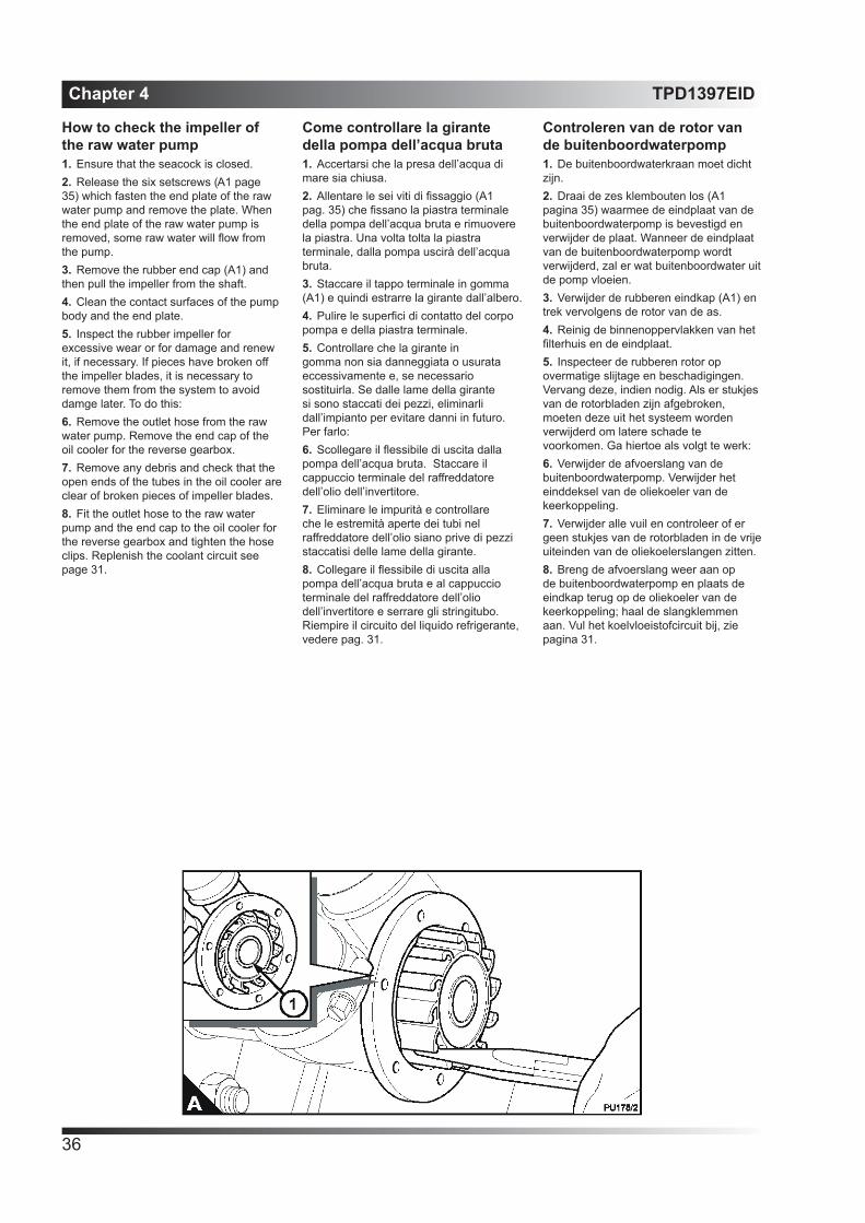
Chapter 4 TPD1397EID
36
How to check the impeller of the raw water pump1. Ensure that the seacock is closed.2. Release the six setscrews (A1 page 35) which fasten the end plate of the raw water pump and remove the plate. When the end plate of the raw water pump is removed, some raw water will flow from the pump.3. Remove the rubber end cap (A1) and then pull the impeller from the shaft.4. Clean the contact surfaces of the pump body and the end plate. 5. Inspect the rubber impeller for excessive wear or for damage and renew it, if necessary. If pieces have broken off the impeller blades, it is necessary to remove them from the system to avoid damge later. To do this:6. Remove the outlet hose from the raw water pump. Remove the end cap of the oil cooler for the reverse gearbox.7. Remove any debris and check that the open ends of the tubes in the oil cooler are clear of broken pieces of impeller blades.8. Fit the outlet hose to the raw water pump and the end cap to the oil cooler for the reverse gearbox and tighten the hose clips. Replenish the coolant circuit see page 31.
Come controllare la girante della pompa dell’acqua bruta1. Accertarsi che la presa dell’acqua di mare sia chiusa.2. Allentare le sei viti di fissaggio (A1 pag. 35) che fissano la piastra terminale della pompa dell’acqua bruta e rimuovere la piastra. Una volta tolta la piastra terminale, dalla pompa uscirà dell’acqua bruta.3. Staccare il tappo terminale in gomma (A1) e quindi estrarre la girante dall’albero.4. Pulire le superfici di contatto del corpo pompa e della piastra terminale. 5. Controllare che la girante in gomma non sia danneggiata o usurata eccessivamente e, se necessario sostituirla. Se dalle lame della girante si sono staccati dei pezzi, eliminarli dall’impianto per evitare danni in futuro. Per farlo:6. Scollegare il flessibile di uscita dalla pompa dell’acqua bruta. Staccare il cappuccio terminale del raffreddatore dell’olio dell’invertitore.7. Eliminare le impurità e controllare che le estremità aperte dei tubi nel raffreddatore dell’olio siano prive di pezzi staccatisi delle lame della girante.8. Collegare il flessibile di uscita alla pompa dell’acqua bruta e al cappuccio terminale del raffreddatore dell’olio dell’invertitore e serrare gli stringitubo. Riempire il circuito del liquido refrigerante, vedere pag. 31.
Controleren van de rotor van de buitenboordwaterpomp1. De buitenboordwaterkraan moet dicht zijn.2. Draai de zes klembouten los (A1 pagina 35) waarmee de eindplaat van de buitenboordwaterpomp is bevestigd en verwijder de plaat. Wanneer de eindplaat van de buitenboordwaterpomp wordt verwijderd, zal er wat buitenboordwater uit de pomp vloeien.3. Verwijder de rubberen eindkap (A1) en trek vervolgens de rotor van de as.4. Reinig de binnenoppervlakken van het filterhuis en de eindplaat. 5. Inspecteer de rubberen rotor op overmatige slijtage en beschadigingen. Vervang deze, indien nodig. Als er stukjes van de rotorbladen zijn afgebroken, moeten deze uit het systeem worden verwijderd om latere schade te voorkomen. Ga hiertoe als volgt te werk:6. Verwijder de afvoerslang van de buitenboordwaterpomp. Verwijder het einddeksel van de oliekoeler van de keerkoppeling.7. Verwijder alle vuil en controleer of er geen stukjes van de rotorbladen in de vrije uiteinden van de oliekoelerslangen zitten.8. Breng de afvoerslang weer aan op de buitenboordwaterpomp en plaats de eindkap terug op de oliekoeler van de keerkoppeling; haal de slangklemmen aan. Vul het koelvloeistofcircuit bij, zie pagina 31.

TPD1397EID Chapter 4
37
9. Apply Spheerol SX2 grease or liquid soap to the blades of the impeller and fit the impeller into the housing with the blades bent clockwise (A page 36). Fit the rubber end cap.10. Apply POWERPART jointing compound, part number 1861117 to a new joint and fit it to the body with the wide area of the joint over the eccentric plate in the body. Fit the end plate and tighten the end plate screws.11. Open the seacock.
9. Applicare del grasso Spheerol SX2 o del sapone liquido sulle lame della girante e montare la girante nell’alloggiamento con le lame piegate in senso orario (A). Montare il cappuccio terminale in gomma.10. Applicare il mastice POWERPART, parte numero 1861117 su una nuova guarnizione e montarla sul corpo con la zona larga della guarnizione sopra l’eccentrico nel corpo pompa. Montare la piastra terminale e serrarne le viti.11. Aprire la presa dell’acqua di mare..
9. Gebruik Spheerol SX2 vet of vloeibare zeep voor de rotorbladen en breng de rotor aan in de behuizing met de bladen rechts herum (A). Breng de rubberen eindkap aan.10. Breng POWERPART borgmiddel nr. 1861117 aan op de nieuwe verbinding en breng deze aan op de behuizing, met het grootste deel over de excentrische plaat in de behuizing. Breng de eindplaat aan en haal de eindplaatschroeven aan.11. Open de buitenboordkraan.

Chapter 4 TPD1397EID
38
How to check the drive beltPress down the belt with the thumb at the centre of the longest free length and check the deflection (A). With moderate thumb pressure - 45N (10 lbf) 4,5 kgf - the correct deflection of the belt is 10 mm (3/8 in).
How to adjust the belt tensionCaution: The alternator is driven by a drive belt of a specific design. Use only a Perkins POWERPART drive belt. If this is not done, an early failure of the belt may occur.1. Loosen the pivot fastener (A1) of the alternator and loosen the setscrews (A2) and (A3) of the adjustment link.2. Change the position of the alternator to give the correct tension. Tighten the pivot fasteners of the alternator and the setscrew of the adjustment link.3. Check the belt tension again to ensure that it is still correct. If a new belt is fitted, the belt tension must be checked again after the first 25 hours of operation.
Come controllare la cinghia trapezoidalePremere la cinghia con il pollice al centro del tratto sospeso più lungo e controllare la flessione (A). Esercitando una pressione media del pollice - 45N, 4,5 kgf - la flessione corretta della cinghia è di 10 mm.
Come regolare la tensione della cinghiaAttenzione: L’alternatore è azionato da una cinghia trapezoidale di tipo specifico. Usare solo una cinghia di trasmissione POWERPART Perkins. In caso contrario, la cinghia potrebbe danneggiarsi prematuramente.1. Allentare il fermo orientabile (A1) dell’alternatore e le viti di fissaggio (A2) e (A3) del tirante di regolazione.2. Modificare la posizione dell’alternatore per ottenere la tensione corretta. Serrare i fermi orientabili dell’alternatore e la vite di fissaggio del tirante di regolazione.3. Controllare nuovamente la tensione della cinghia per assicurarsi che sia ancora corretta Se viene montata una nuova cinghia, la tensione deve essere controllata di nuovo dopo le prime 25 ore di funzionamento.
Controleren van de aandrijfriemDe riem met de duim in het midden van de langste vrije lengte indrukken en de doorbuiging (A) controleren. Bij een gemiddelde duimdruk - 45 N / 4,5 kgf - is de correcte doorbuiging van de snaar 10 mm.
Afstellen van de aandrijfriemVoorzichtig: De wisselstroomdynamo wordt aangedreven door een speciaal type aandrijfriem. Gebruik uitsluitend een Perkins POWERPART aandrijfriem. Indien dit niet gebeurt, kan de aandrijfriem eerder defect raken.1. Maak de scharnierbevestigingen (A1) van de wisselstroomdynamo en de klembouten (A2) en (A3) van de verstelbare steun los.2. Zet de wisselstroomdynamo zo dat de juiste spanning wordt verkregen. Haal de scharnierbevestigingen van de wisselstroomdynamo en de verstelbare steun aan.3. Controleer opnieuw of de riemspanning nog steeds correct is. Wanneer een nieuwe riem wordt aangebracht, moet de riemspanning na de eerste 25 werkuren opnieuw worden gecontroleerd.

TPD1397EID Chapter 4
39
How to renew the element of the fuel filterWarning! Discard the used canister and fuel oil in a safe place and in accordance with local regulations.Caution: It is important that only the genuine Perkins parts are used. The use of wrong parts could damage the fuel injection equipment.1. Thoroughly clean the outside surfaces of the fuel filter assembly.2. Loosen the drain device (A4) at the bottom of the filter canister and drain the fuel into a suitable container.3. Use a strap wrench or similar tool to loosen the filter canister. Remove the filter canister.4. Ensure that the threaded adaptor (A1) is secure in the filter head and that inside filter head is cleanCaution: Some fuel filters fitted in the factory have a special sealant applied to the threads of th adaptor. Fuel filters supplied in service have an inner seal assembly (A2) instead. The seal is held in position by a plastic clip. Damage to the fuel injection pump may occur if the canister seals are not fitted correctly.5. Lubricate lightly the two top seals (A2) and (A3) of the new canister with clean fuel. Fit the new canister t o the filter head and tighten by hand 1/2 to 3/4 turn.6. Eliminate the air from the fuel filter see page 43.
Come sostituire la cartuccia del filtro del combustibilePericolo! Smaltire la cartuccia e l’olio usato in un luogo sicuro e conformemente alla legislazione vigente.Attenzione: È importante usare solo parti di ricambio originali Perkins. L’impiego di parti sbagliate potrebbe danneggiare l’apparato di iniezione.1. Pulire a fondo le superfici esterne del filtro.2. Allentare il dispositivo di scarico (A4) alla base della cartuccia del filtro e scaricare il combustibile in un contenitore adatto.3. Usare una chiave a nastro o un attrezzo simile per allentare la cartuccia del filtro. Rimuovere la cartuccia del filtro.4. Controllare che l’adattatore filettato (A1) sia saldo nella testa del filtro e che l’interno della testa sia pulitoAttenzione: Alcune delle cartucce del filtro del combustibile montate in fabbrica hanno uno speciale sigillante applicato sui filetti dell’adattatore. I filtri del combustibile forniti in assistenza hanno invece una tenuta interna (A2). La tenuta viene fissata in posizione da una fascetta di plastica. La pompa di iniezione può subire danni se le tenute delle cartucce non sono montate correttamente.5. Lubrificare leggermente le due tenute superiori (A2) e (A3) della nuova cartuccia con combustibile pulito. Avvitare la nuova cartuccia sulla testa del filtro e serrare a mano da 1/2 a 3/4 di giro.6. Spurgare l’aria dal filtro del combustibile, vedere pag. 43..
Vervangen van het brandstoffilterelementWaarschuwing! Gooi het gebruikte filter en de weggelekte brandstof weg in overeenstemming met de ter plaatse geldende voorschriften.Voorzichtig: Er mogen uitsluitend originele Perkins onderdelen worden gebruikt. Bij gebruik van een verkeerd element kan de brandstofinspuitpomp beschadigd raken.1. Reinig de buitenoppervlakken van het brandstoffilter grondig.2. Draai het aftapelement aan de onderzijde van het filter (A4) los en laat de brandstof weglopen in een geschikte opvangbak.3. Gebruik een bandsleutel of soortgelijk instrument om het filterelement iets los te draaien. Verwijder de filterhouder.4. Zorg ervoor dat de adapter met schroefdraad (A1) goed vastzit in de filterkop en dat de binnenzijde van de kop schoon is.Voorzichtig: Sommige brandstoffilter-bussen die in de fabriek zijn aangebracht hebben een adapter waarvan de schroefdraad is voorzien van een speciaal afdichtmiddel. Filterhouders die naderhand worden geleverd hebben in plaats daarvan een inwendige pakking (A2). De pakking wordt door een plastic klem op zijn plaats gehouden. Wanneer de pakkingen van de houder niet goed zijn aangebracht kan dit beschadiging van de brandstofinspuitpomp veroorzaken.5. Smeer de bovenste twee pakkingen (A2) en (A3) van de nieuwe filterhouder lichtjes met schone brandstof. Breng de nieuwe houder aan op de filterkop en draai deze met de hand 1/2 - 3/4 slag aan.6. Laat de lucht uit het brandstoffilter ontsnappen, zie pagina 43.

Chapter 4 TPD1397EID
40
Fuel pre-filterThis will normally be fitted between the fuel tank and the engine. Check the filter bowl for water at regular intervals and drain as necessary.
Atomiser maintenanceCaution: A faulty atomiser must be renewed by a person who has had the correct training.Regular maintenance of the atomisers is not necessary. The atomiser nozzles should be renewed and not cleaned, and renewed only if an atomiser fault occurs. See section 6 for fault diagnosis.
Atomiser faultWarnings!• If your skin comes into contact with high-pressure fuel, obtain medical assistance immediately.• Keep away from moving parts during engine operation. Some moving parts cannot be seen clearly while the engine runs.An atomiser fault can cause an engine misfire.In order to find which atomiser is defective, operate the engine at a fast idle speed. Loosen and tighten the union nut (A1) of the high-pressure fuel pipe at each atomiser. When the union nut of the defective atomiser is loosened, it has little or no effect on the engine speed.
Prefiltro del combustibileQuesto prefiltro è di solito montato tra il serbatoio del combustibile e il motore. Controllare ad intervalli regolari che la tazza del filtro non contenga acqua e svuotarla come richiesto.
Manutenzione dell’iniettoreAttenzione: Un iniettore difettoso deve essere sostituito solo da personale opportunamente addestrato.Non è necessaria una manutenzione regolare degli iniettori. Gli ugelli degli iniettori devono essere sostituiti e non puliti e devono essere sostituiti solo in caso di difetto. Consultare la sezione 6 per la diagnosi dei difetti.
Iniettore difettosoPericolo!• Se il combustibile sotto pressione colpisce l’epidermide, rivolgersi immediatamente alle cure di un medico.• Tenersi lontano dalle parti in movimento durante il funzionamento del motore. Alcune parti in movimento non sono chiaramente visibili durante il funzionamento del motore.Un iniettore guasto può causare la mancata accensione del motore.Per trovare l’iniettore difettoso, far funzionare il motore a un regime del minimo veloce. Allentare e serrare il dado di raccordo (A1) della tubazione di alta pressione di ciascun iniettore. Quando si allenta il dado di raccordo dell’iniettore difettoso, si ha una variazione minima o nulla del regime.
BrandstofvoorfilterNormaal gesproken bevindt het brandstofvoorfilter zich tussen de brandstoftank en de motor. Controleer het filterhuis met regelmatige tussenpozen op water en tap, indien nodig, af.
Onderhoud van de verstuiverVoorzichtig: Een defecte verstuiver moet worden vervangen door een persoon die de juiste training heeft ontvangen.De verstuivers hebben geen regelmatig onderhoud nodig. De mondstukken van de verstuivers moeten niet worden gereinigd, maar moeten worden vervangen en slechts dan wanneer de verstuiver defect is. Zie sectie 6 voor het opsporen en verhelpen van storingen.
Defecte verstuiverWaarschuwing!• Indien de huid in contact komt met brandstof onder hoge druk, onmiddellijk medische hulp inroepen.• Blijf uit de buurt van bewegende delen wanneer de motor draait. Sommige bewegende delen zijn niet duidelijk zichtbaar wanneer de motor draait.Door een defecte verstuiver kan de motor overslaan.Om te bepalen welke verstuiver defect is, dient de motor met versneld stationair toerental te draaien. Draai de wartelmoer (A1) van de hogedrukbrandstofleiding van elke verstuiver los en haal deze aan. Wanneer de verbindingsmoer van de defecte verstuiver wordt losgedraaid, heeft dit weinig of geen effect op het motortoerental.

TPD1397EID Chapter 4
41
How to renew an atomiserCautions:• Atomiser must be removed and fitted by a person with the correct training.• Do not allow dirt to enter the fuel system. Before a connection is disconnected, clean thoroughly the area around the connection. After a component has been disconnected, fit a suitable cover to all open connections.1. Clean thoroughly the area around the atomiser to be removed.2. Remove the fuel leak-off pipe from the connection (A2).3. Remove the union nuts of the high-pressure pipe from the atomiser and from the fuel injection pump. Do not bend the pipe. If necessary, remove the pipe clamps. Fit a plastic cap (A1) to cover the fuel inlet connectrion.Caution: Remove and discard the seat washer (A5). If the original seat washer remains in the recess for the atomiser, the nozzle protrusion will be incorrect when a new seat washer is added. This will affect engine performance.4. Release the clamp nut (A3) and remove the atomiser and its seat washer from the recess in the cylinde head.5. Thoroughly clean the threads of the clamp nut and the clinder head.
Come sostituire un iniettoreAttenzione:• Gli iniettori devono essere smontati e rimontati da personale opportunamente addestrato.• Evitare l’ingresso di sporcizia nell’impianto di alimentazione. Prima di scollegare un raccordo, pulire a fondo la zona circostante. Dopo aver scollegato un componente, montare un coperchio idoneo su tutti i raccordi aperti.1. Pulire a fondo la zona attorno all’iniettore da sostituire.2. Scollegare la tubazione di recupero del combustibile dal raccordo (A2).3. Svitare i dadi di raccordo della tubazione dell’alta pressione dall’iniettore e dalla pompa di iniezione. Non piegare la tubazione. Se necessario staccare le fascette. Montare un tappo di plastica (A1) per coprire il raccordo di entrata del combustibile.Attenzione: Sfilare e scartare la rondella della sede (A5). Se la rondella originale della sede rimane nel recesso dell’iniettore, la sporgenza dell’ugello sarà errata quando si aggiunge una nuova rondella della sede. Questo fatto influirà negativamente sul rendimento del motore.4. Allentare il dado del morsetto (A3) e smontare l’iniettore e la rispettiva rondella della sede dalla gola nella testata.5. Pulire a fondo i filetti del dado del morsetto e della testata.
Vervangen van een verstuiverVoorzichtig:• De verstuivers moeten worden verwijderd en aangebracht door een persoon met de juiste opleiding.• Zorg ervoor dat geen vuil in het brandstofsysteem kan komen. Reinig, alvorens een aansluiting los te maken, de ruimte rondom deze aansluiting grondig. Nadat een onderdeel is losgemaakt, dient een passende afdichting te worden aangebracht over alle open aansluitingen.1. Maak het gebied rond de te verwijderen verstuiver grondig schoon.2. Verwijder de brandstofretourleiding van de aansluiting (A2).3. Verwijder de wartelmoeren van de hogedrukleiding van de verstuiver en van de brandstofinspuitpomp. Buig de leiding niet. Verwijder, indien nodig, de leidingklemmen. Breng een plastic dop (A1) aan over de aansluiting van de brandstofinlaat.Voorzichtig: Verwijder de sluitring van de zitting en gooi deze weg (A5). Indien de originele sluitring in de uitsparing voor de verstuiver blijft zitten, steekt de verstuivernaald incorrect uit wanneer een nieuwe sluitring wordt aangebracht. Dit heeft invloed op de prestaties van de motor.4. Draai de klemmoer (A3) los en verwijder de verstuiver en de sluitring van de zitting uit de uitsparing in de cilinderkop.5. De schroefdraad van de klemmoer en de cilinderkop grondig reinigen.

Chapter 4 TPD1397EID
42
Caution: Do not allow any thread sealant to get below the clamp nut thread.6. Ensure that the wire clip (A7) is in position. Put a 6,0 mm (0.24 in) long, 1,0 mm (0.04 in) wide bead of POWERPART Jointing compound, part number 1861117, around the first two threrads of the atomiser clamp nut.7. Put the new seat washer (A5) into the seat recess in the cylinder head.8. Put the atomiser in position, ensure that the location ball (A6) is fitted in correctly in the groove (A4). Carefully engage the threads of the clamp nut with the threads in the cylinder head and tighten the nut to 30 Nm (23 lbf ft) 3,0 kgf m. As the nut is tightened the atomiser will rotate clockwise as the ball moves in the slot. Remove any excess thread sealant. Do not move the clamp nut after it has been tightened as this can cause a leakage past the threads.Cautions:• If there is a fuel leakage from the union
nut, ensure that the pipe is correctly aligned with the atomiser inlet.
• Do not tighten the union nuts of the high-pressure pipes more than the recommended torque tension as this can cause a restriction at the end of the pipe. This can affect the supply of fuel to the atomiser.
9. Remove the plastic cap and fit the high-pressure fuel pipe and tighten the union nuts to 27 Nm (20 lbf ft) 2,8 kgf m. If necessary, fit the pipe clamps.10. Renew the sealing washers and fit the leak-off pipe. Tighten the banjo bolts to 9,0 Nm (7.0 lbf ft) 0,9 kgf m.11. Eliminate air from the fuel system, see page 43.12. Operate the engine and check for leakage of fuel and air.
Attenzione: Non lasciare che il sigillante per filetti passi oltre i filetti del dado del morsetto.6. Accertarsi che il fermo metallico (A7) sia montato. Stendere una striscia lunga 6,0 mm e larga 1,0 mm di mastice POWERPART, parte numero 1861117, attorno ai primi due filetti del dado del morsetto dell’iniettore.7. Infilare una nuova rondella della sede (A5) nella gola della sede nella testata.8. Posizionare l’iniettore, assicurarsi che la sfera di centraggio (A6) sia inserita correttamente nella scanalatura (A4). Avvitare con attenzione il dado del morsetto sui filetti nella testata e serrare il dado a 30 Nm, 3,0 kgf m. Mentre il dado viene serrato, l’iniettore ruota in senso orario dato che la sfera si sposta nella fessura. Togliere ogni eccesso di sigillante per filetti. Non spostare il dado del morsetto dopo averlo serrato dato che si potrebbe causare una perdita dai filetti.Attenzione:• Se si verifica una perdita dal raccordo,
assicurarsi che il tubo sia allineato correttamente rispetto al raccordo di entrata dell’iniettore.
• Non serrare i dadi di raccordo delle tubazioni dell’alta pressione oltre la coppia di serraggio raccomandata dato che si potrebbe causare un intasamento all’estremità della tubazione. Questo intasamento potrebbe influire negativamente sull’alimentazione di combustibile dell’iniettore.
9. Togliere il tappo in plastica per collegare la tubazione dell’alta pressione e quindi serrare i dadi di raccordo a 27 Nm, 2,8 kgf m. Se necessario, montare le fascette.10. Sostituire le rondelle di tenuta e collegare la tubazione di recupero. Serrare i bulloni del raccordo orientabile a 9,0 Nm, 0,9 kgf m.11. Spurgare l’aria dall’impianto di alimentazione, vedere pag. 43.12. Azionare il motore e controllare che non vi siano perdite di combustibile o aria.
Voorzichtig: Zorg dat het afdichtmiddel van de schroefdraad niet lager dan de schroefdraad van de klemmoer komt.6. Zorg ervoor dat de draadklem (A7) is aangebracht. Breng een rand met POWERPART afdichtmiddel nr. 1861117 met een lengte van 6,0 mm (0,24 in) lang en een breedte van 1 mm (0,04 in) aan rond de eerste twee schroefdraden van de klemmoer van de verstuiver.7. Breng de nieuwe sluitring van de zitting (A5) aan in de uitsparing in de cilinderkop.8. Breng de verstuiver aan en zorg ervoor dat de bevestigingskogel (A6) correct in de groef (A4) wordt aangebracht. Carefully engage the threads of the clamp nut with the threads in the cylinder head and tighten the nut to 30 Nm (23 lbf ft) 3,0 kgf m. As the nut is tightened the atomiser will rotate clockwise as the ball moves in the slot. Verwijder overtollig draadborgmiddel. Verplaats de klemmoer niet nadat deze is aangehaald omdat dan lekkage via de schroefdraad kan optreden. Voorzichtig:• Indien er sprake is van
brandstoflekkage bij de verbindingsmoer, controleer dan of de leiding correct is uitgelijnd met de verstuiverinlaat.
• Haal de verbindingsmoer van de verstuiver niet strakker aan dan het aanbevolen aanhaalmoment, omdat dit ertoe kan leiden dat het uiteinde van de leiding wordt vernauwd. Dit kan van invloed zijn op de brandstoftoevoer naar de verstuiver.
9. Verwijder de plastic dop, bevestig de hogedrukbrandstofleiding en haal de wartelmoeren aan tot 27 Nm / 2,8 kgf m. Breng, indien nodig, de leidingklemmen aan.10. Vervang de sluitringen en breng de retourleiding aan. Haal de banjobouten aan met 9,0 Nm (7,0 lbf ft) / 0,9 kgf m.11. Verwijder de lucht uit het brandstofsysteem, zie pagina 43.12. Start de motor en controleer op olie- en luchtlekkage.

TPD1397EID Chapter 4
43
How to eliminate air from the fuel systemCaution: When air is to be eliminated from the fuel system, only use the starter motor to start the engine after air has been eliminated from the low-pressure side of the fuel system.If air enters the fuel system, it must be eliminated before the engine can be started.Air can enter the system if:• The fuel tank is drained during normal operation.• The low-pressure fuel pipes are disconnected.• A part of the low-pressure fuel system leaks during engine operation.Caution: Do not allow fuel from the engine to contaminate the engine compartment. Put a drip tray under the engine and discard old fuel in accordance with local instructions. 1. Loosen the banjo bolt (A1) on the top of the fuel filter head. Operate the priming lever of the fuel lift pump (B) until fuel, free from air, comes from the vent point. Tighten the banjo bolt.2. Loosen the high-pressure connections at two of the atomisers (A2). Operate the starter motor for intervals of 15 seconds until fuel free from air comes from the pipe connections. Tighten the connections to 27 Nm (16 lbf ft) 2,2 kgf m.3. Operate the starter motor for intervals of 15 seconds until the engine starts. If the engine runs correctly for a short time and then stops or runs roughly, check for air in the fuel system. If there is air in the fuel system, there is probably a leakage in the low pressure system. Stop the engine and check for air leaks.
Come spurgare l’aria dall’impianto di alimentazioneAttenzione: Quando l’aria deve essere spurgata dall’impianto di alimentazione, usare solo il motorino di avviamento per avviare il motore dopo avere spurgato l’aria dal lato di bassa pressione dell’impianto di alimentazione.Se l’aria penetra nell’impianto di alimentazione, deve essere spurgata prima di poter far funzionare il motore.L’aria può entrare nell’impianto se:• Il serbatoio del combustibile viene svuotato durante il normale funzionamento.• Le tubazioni del combustibile a bassa pressione sono scollegate.• Una parte dell’impianto di alimentazione a bassa pressione perde durante il funzionamento del motore.Attenzione: Non permettere al combus-tibile presente nel motore di contaminare il vano motore. Infilare un vassoio di raccolta sotto il motore e smaltire il combustibile versato nel pieno rispetto delle leggi vigenti. 1. Allentare il bullone del raccordo orientabile (A1) sulla parte superiore della testa del filtro del combustibile.Azionare la leva di adescamento della pompa di alimentazione (B) fino a quando dal punto di sfiato esce combustibile privo di aria. Serrare il bullone del raccordo orientabile.2. Allentare i raccordi dell’alta pressione su due degli iniettori (A2). Azionare il motorino di avviamento per 15 secondi alla volta fino a quando dai raccordi delle tubazioni esce aria priva di combus-tibile.Serrare i raccordi a 27 Nm, 2,2 kgf m.3. Azionare il motorino di avviamento a intervalli di 15 secondi alla volta fino a quando il motore parte. Se il motore funziona correttamente per un breve periodo e poi si ferma o funziona in modo irregolare, controllare che non vi sia aria nell’impianto di alimentazione. Se vi è aria nell’impianto di alimentazione, significa che vi è probabilmente una perdita nel circuito di bassa pressione. Spegnere il motore e controllare se vi sono perdite di aria.
Ontluchten van het brandstofsysteemVoorzichtig: Wanneer het brandstofsysteem moet worden ontlucht, gebruik dan de startmotor alleen voor het starten van de motor nadat de lucht is weggestroomd uit de lage-drukzijde van het brandstofsysteem.Wanneer lucht in het brandstofsysteem terecht komt, moet deze worden verwijderd voordat de motor kan worden gestart.Er kan lucht in het systeem terecht komen wanneer:• De brandstoftank wordt afgetapt wanneer de motor in normaal bedrijf is.• De lage-drukbrandstofleidingen los zijn.• Een gedeelte van het lage-drukbrandstofsysteem lekt terwijl de motor in bedrijf is.Voorzichtig: Zorg er voor dat de motorruimte niet verontreinigd kan raken door brandstof uit de motor. Plaats een opvangbak onder de motor en gooi oude brandstof weg in overeenstemming met de ter plaatse geldende richtlijnen. 1. Draai de banjobout (A1) aan de bovenzijde van het brandstoffilter los. Bedien de opvoerhefboom (B) van de brandstofopvoerpomp totdat brandstof zonder lucht uit het ventilatiepunt komt. Haal de banjobout aan.2. Draai de hogedrukaansluitingen bij de twee verstuivers (A2) los. Bedien de startmotor telkens gedurende 15 sec. totdat brandstof, vrij van lucht, uit de slangaansluitingen tevoorschijn komt. Haal de banjobouten aan met 27 Nm (16 lbf ft) / 2,2 kgf m.3. Bedien de startmotor steeds 15 seconden tot de motor start. Wanneer de motor enige tijd goed draait en vervolgens afslaat of sputtert, controleer dan op lucht in het brandstofsysteem. Indien zich lucht in het brandstofsysteem bevindt, is er mogelijk sprake van lekkage in het lagedruksysteem. Stop de motor en controleer deze op luchtlekkages.

Chapter 4 TPD1397EID
44
How to renew the lubricating oilWarning! Discard the used lubricating oil in a safe place and in accordance with local regulations.Note: Renew the filter canister when the lubricating oil is renewed.1. Hold the adaptor on the flywheel housing with a spanner (A1) and use another spanner to release the union nut (A2) on the drain pipe for the lubricating oil.2. Connect the pipe to a sump drain pump (B1). Pump the lubricating oil into a suitable container with a capacity of approximately 10 litres (17.5 pints), the lubricating oil should be drained while it is still hot.3. Disconnect the pipe from the pump and connect the pipe to the adaptor on the flywheel housing. Tighten the connection. Remove the container of used lubricating oil.4. Clean the area around the filler cap on top of the rocker cover and remove the cap.Caution: Do not fill the sump past the notch (C1) on the dipstick (C2) as this can have an adverse affect on on the performance of the engine. Excess lubricating oil must be drained from the sump. An excess of lubricating oil could enter the engine breather valve. This could cause the engine speed to increase rapidly without control.5. Add slowly, approximately 7,0 litres (15.8 pints) of new and clean lubricating oil of an approved specification to the engine, see page 61. Allow the oil enough time to pass to the sump, remove the dipstick (C2) and ensure that the lubricating oil is to the full mark (C1). The oil level must not be above the full mark. If it is, the engine could be damaged.
Come sostituire l’olio lubrificantePericolo! Smaltire l’olio lubrificante usato in un luogo sicuro e nel pieno rispetto delle leggi vigenti.Nota: Sostituire la cartuccia del filtro quando si cambia l’olio lubrificante.1. Tenere fermo l’adattatore sull’alloggiamento del volano usando una chiave (A1) e usare una seconda chiave per allentare il dado di raccordo (A2) sulla tubazione di scarico dell’olio lubrificante.2. Collegare la tubazione alla pompa di scarico della coppa (B1). Pompare l’olio lubrificante in un contenitore idoneo con una capacità di 10 litri circa. L’olio lubrificante deve essere scaricato mentre è ancora caldo.3. Scollegare la tubazione dalla pompa e collegare la tubazione all’adattatore sull’alloggiamento del volano. Serrare il raccordo. Estrarre il contenitore di olio lubrificante usato.4. Pulire la zona attorno al tappo di rifornimento sulla parte superiore del coperchio bilancieri e togliere il coperchio.Attenzione: Non riempire la coppa oltre l’indice (C1) sull’astina di livello (C2) dato che così facendo si potrebbe influire negativamente sul rendimento del motore. L’olio lubrificante in eccesso deve essere scaricato dalla coppa. L’olio lubrificante in eccesso potrebbe infatti penetrare nella valvola di sfiato e causare l’aumento rapido del regime motore senza controllo.5. Aggiungere lentamente 7,0 litri circa di olio lubrificante nuovo e pulito di tipo approvato per il motore in oggetto, vedere pag. 61. Dare tempo all’olio di arrivare nella coppa, sfilare l’astina di livello (C2) e controllare che il livello dell’olio raggiunga l’indice di pieno (C1). Il livello dell’olio non deve superare l’indice di pieno. In caso contrario, il motore potrebbe subire danni.
Verversen van de olieWaarschuwing! Gooi afgewerkte motorolie weg in overeenstemming met de te plaatse geldende richtlijnen.Let op: Vervang het filterelement wanneer de olie wordt ververst.1. Blokkeer de adapter op de vliegwielbehuizing met een tang (A1) en gebruik een andere tang om de koppelingsmoer (A2) op de smeerolie-aftapleiding los te draaien.2. Sluit de leiding aan op een carteraftappomp (B1). Pomp de smeerolie in een daartoe geschikte opvangbak met een inhoud van ca. 10 l (17,5 pints); de smeerolie dient te worden afgetapt terwijl deze nog heet is.3. Maak de pijp los van de pomp en sluit de pijp aan op de adapter op de vliegwielbehuizing. Haal de verbinding aan. Verwijder de opvangbak met afgewerkte smeerolie.4. Maak het gebied rond de vuldop bovenop het kleppendeksel schoon en verwijder de dop.Voorzichtig: Vul het oliecarter niet verder dan de inkeping (C1) op de peilstok (C2) daar dit een negatief effect kan hebben op de prestaties van de motor. Overtollige olie moet uit het carter worden afgetapt. Overtollige olie kan in de motorventilatie binnendringen. Hierdoor kan het motortoerental plotseling snel oplopen.5. Vul langzaam ca. 7,0 l (15,8 pints) nieuwe en schone smeerolie van een goedgekeurde kwaliteit bij in de motor; zie ook pag. 61. Geef de olie de tijd om naar het carter te zakken, verwijder de peilstok (C2) en controleer of de smeerolie tot aan het “vol”-merkteken (C1) komt. Het oliepeil mag niet boven het “vol”-merkteken uitkomen. Wanneer dit gebeurt, kan de motor beschadigd raken.

TPD1397EID Chapter 4
45
6. Fit the filler cap and ensure that the dipstick is fitted correctly in the dipstick tube.7. Start the engine and check for lubricating oil leakage. Stop the engine. After 15 minutes check the oil level on the dipstick and, if necessary, put more lubricating oil into the sump.
6. Montare il tappo di rifornimento e controllare che l’astina di livello sia infilata in modo corretto nel rispettivo tubetto.7. Avviare il motore e controllare se vi sono perdite di olio lubrificante. Spegnere il motore. Dopo 15 minuti, controllare il livello dell’olio sull’astina di livello e, se necessario, versare dell’altro olio lubrificante nella coppa.
6. Breng de vuldop aan en controleer of de peilstok correct in de peilstokhouder is aangebracht.7. Start de motor en controleer op olielekkage. Zet de motor af. Controleer na 15 minuten het peil op de oliepeilstok; indien nodig bijvullen..

Chapter 4 TPD1397EID
46
How to renew the canister of the lubricating oil filterWarning! Discard the used canister and lubricating oil in a safe place and in accordance with local regulations.1. Clean thoroughly the outside surfaces of the oil filter.2. Use a strap wrench or similar tool to just loosen the filter canister (A1). Put a suitable container under the filter assembly to retain spilt oil. Remove and discard safely the canister. Ensure that the adaptor (A3) is secure in the lubricating oil cooler.3. Clean the contact face of the lubricating oil cooler.4. Lubricate the seal (A2) on top of the canister with clean engine lubricating oil.5. Fit the new canister and tighten by hand until the seal contacts the cylinder block. Tighten the canister a further 1/2 to 3/4 of a turn by hand only. Do not use a strap wrench.6. Ensure that there is lubricating oil in the sump. Start the engine and run at idle speed until oil pressure is obtained. Check for leakage from the filter. Stop the engine. After 15 minutes check the oil level on the dipstick and, if necessary, put more lubricating oil into the sump.Cautions:• Do not fill the sump past the notch (C1 page 44) on the dipstick.• The canister contains a valve and special tube to ensure that lubricating oil does not drain from the filter. Therefore, ensure that the correct Perkins POWERPART canister is used.
Come sostituire la cartuccia del filtro dell’olio lubrificantePericolo! Smaltire la cartuccia e l’olio lubrificante usati in un luogo sicuro e nel pieno rispetto delle leggi vigenti.1. Pulire a fondo le superfici esterne del filtro dell’olio.2. Usare una chiave a nastro o un attrezzo simile per allentare appena la cartuccia del filtro (A1). Infilare un contenitore idoneo sotto il filtro per recuperare l’olio versato. Estrarre e smaltire in modo sicuro la cartuccia. Controllare che l’adattatore (A3) sia ben saldo sul monoblocco o sul raffreddatore dell’olio lubrificante.3. Pulire la superficie di contatto del raffreddatore dell’olio lubrificante.4. Lubrificare la tenuta (A2) sulla parte superiore della cartuccia con olio motore pulito.5. Montare una nuova cartuccia e serrarla a mano fino a quando la tenuta fa contatto con il monoblocco. Serrare la cartuccia di un altro 1/2 a 3/4 di giro solo a mano. Non usare una chiave per filtri.6. Accertarsi che vi sia olio lubrificante nella coppa. Avviare il motore e farlo funzionare al minimo fino a quando si ottiene la pressione dell’olio. Controllare se vi sono perdite dal filtro. Spegnere il motore. Dopo 15 minuti, controllare il livello dell’olio sull’astina di livello e, se necessario, versare dell’altro olio lubrificante nella coppa.Attenzione:• Non riempire la coppa oltre l’indice (C1 pag. 44) sull’astina di livello.• La cartuccia contiene una valvola e un tubetto speciale per fare in modo che l’olio lubrificante non scoli dal filtro. Assicurarsi quindi di usare sempre la corretta cartuccia POWERPART della Perkins.
Vervangen van het filterelement voor het oliefilterWaarschuwing! Gooi het gebruikte element en de afgewerkte motorolie weg in overeenstemming met de ter plaatse geldende richtlijnen.1. Reinig zorgvuldig de buitenzijden van het oliefilter.2. Gebruik een bandsleutel of soortgelijk instrument om het filterelement (A1) iets los te draaien. Plaats een bak onder het filter om gemorste motorolie in op te vangen. Verwijder het element en gooi dit op de voorgeschreven wijze weg. Zorg ervoor dat de adapter (A3) goed vastzit in de smeeroliekoeler.3. Reinig het pasvlak van de smeeroliekoeler.4. Smeer de pakking (A2) aan de bovenzijde van het filterelement met schone motorolie.5. Breng het nieuwe filterelement aan en draai het handvast aan tot de pakking het cilinderblok raakt. Haal het filterelement nog 1/2 tot 3/4 slag met de hand aan. Gebruik geen bandsleutel.6. Controleer of zich motorolie in het carter bevindt. Start de motor en laat deze stationair draaien tot er oliedruk ontstaat. Controleer het filter op lekkage. Zet de motor af. Controleer na 15 minuten het peil op de oliepeilstok; indien nodig bijvullen.Voorzichtig:• Vul het oliecarter niet verder dan de inkeping (C1 pagina 44) op de peilstok.• Het filterelement is voorzien van een klep en een speciale buis die ervoor zorgen dat er geen olie uit het filter wegloopt. Controleer daarom of het juiste Perkins POWERPART-element wordt gebruikt..

TPD1397EID Chapter 4
47
How to renew the lubricating oil of the Newage PRM 500D reverse gearboxCaution: In service the lubricating oil of these reverse gearboxes should be checked with the lubricating oil cold. Always check the lubricating oil level before the transmission is used.1. Put a suitable container with a capacity of at least 3 litres (5 pints) under the reverse gearbox. Remove the drain plug (A3) and its sealing washer and drain the oil from the reverse gearbox.2. Inspect the sealing washer for the plug and, if necessary, renew it. Fit the drain plug and its sealing washer. Tighten the plug.3. Rotate the hexagonal head of the dipstick (A1) counter-clockwise to release the dipstick and remove it from the dipstick / filler tube. Ensure that the sealing washer is not lost. Add lubricating oil of the correct specification through the dipstick / filler tube, see section 9 for the correct quantity and specification.4. Ensure that the sealing washer is on the dipstick. Fit the dipstick fully into the dipstick / filler tube. Rotate the hexagonal end of the dipstick clockwise until the dipstick is tight in the tube.5. Ensure that the reverse gearbox is in neutral (lever in the centre position). Start the engine to allow the lubricating oil in the reverse gearbox to circulate around the system, approximately 15 seconds. Stop the engine and wait approximately two minutes.
Come sostituire l’olio lubrificante di un invertitore Newage PRM 500D Attenzione: Durante la manutenzione, l’olio lubrificante di questi invertitori deve essere controllato a freddo. Controllare sempre il livello dell’olio lubrificante prima di usare la trasmissione.1. Infilare un contenitore con una capacità minima di 3 litri sotto l’invertitore. Togliere il tappo di scarico (A3) con la rispettiva rondella di tenuta e scaricare l’olio dall’invertitore.2. Ispezionare la rondella di tenuta del tappo e, se necessario, sostituirla. Montare il tappo di scarico e la rispettiva rondella di tenuta. Serrare il tappo.3. Ruotare la testa esagonale dell’astina di livello (A1) in senso antiorario per svitare l’astina ed estrarla dal tubo / bocchettone di rifornimento. Fare in modo di non perdere la rondella di tenuta. Aggiungere olio lubrificante di tipo corretto nel tubo dell’astina di livello/bocchettone di rifornimento; vedere alla sezione 9 la quantità e le caratteristiche tecniche corrette.4. Controllare che sull’astina di livello vi sia la rondella di tenuta. Infilare completamente l’astina di livello nel tubo/bocchettone di rifornimento. Ruotare in senso orario l’estremità esagonale dell’astina di livello fino a quando l’astina è ben salda nel tubo.5. Controllare che l’invertitore sia in folle (leva in posizione centrale). Avviare il motore per 15 secondi circa per permettere all’olio lubrificante nell’invertitore di circolare nell’impianto. Spegnere il motore e attendere due minuti circa.
Het verversen van de olie van de Newage PRM 500D keerkoppelingVoorzichtig: Tijdens een onderhoudsbeurt dient de olie van deze keerkoppelingen te worden gecontroleerd wanneer deze koud is. Controleer het oliepeil altijd voordat de transmissie wordt gebruikt.1. Plaats een daartoe geschikte opvangbak met een inhoud van tenminste 3 l (5 pints) onder de keerkoppeling. Verwijder de aftapplug (A3) met de sluitring en tap de olie af uit de keerkoppeling.2. Controleer de sluitring voor de plug en, indien nodig, vervang deze. Breng de aftapplug en de sluitring weer aan. Haal de plug aan.3. Draai de zeskantkop van de peilstok (A1) tegen de richting van de klok in om de peilstok los te zetten en verwijder de stok uit de peilstok- / vulbuis. Zorg ervoor dat de sluitring niet kwijtraakt. Vul olie met de juiste specificatie bij (zie sectie 9 voor de juiste hoeveelheid en specificatie) via de peilstok-/vulbuis.4. Zorg ervoor dat de sluitring op de peilstok zit. Breng de peilstok volledig in de peilstok-/vulbuis aan. Draai het zeskantige uiteinde van de peilstok met de klok mee totdat de peilstok vastzit in de buis.5. Controleren of de keerkoppeling in de vrij staat. Start de motor en laat de smeerolie in de keerkoppeling ca. 15 sec. circuleren in het circuit. Zet de motor af en wacht ongeveer twee minuten.

Chapter 4 TPD1397EID
48
6. Remove and clean the dipstick. Insert and tighten the dipstick finger tight into the dipstick / filler tube, then immediately remove the dipstick to check the oil level. Check that the oil is at the full mark (A2 page 44) and, if necessary, add more lubricating oil.7. Ensure that the sealing washer is on the dipstick. Fit the dipstick fully into the dipstick / filler tube. Rotate the hexagonal end of the dipstick clockwise until the dipstick is tight in the tube.
6. Sfilare e pulire l’astina di livello. Inserire e serrare a mano l’astina di livello nel rispettivo tubo/bocchettone di rifornimento e quindi toglierla immediatamente per controllare il livello dell’olio. Controllare che l’olio sia al livello massimo pag. 44 e, se necessario, aggiungerne dell’altro.7. Controllare che sull’astina di livello vi sia la rondella di tenuta. Infilare completamente l’astina di livello nel tubo/bocchettone di rifornimento. Ruotare in senso orario l’estremità esagonale dell’astina di livello fino a quando l’astina è ben salda nel tubo..
6. Verwijder en reinig de peilstok. Breng de peilstok volledig aan in de peilstok-/vulbuis en verwijder deze daarna meteen weer om het oliepeil te controleren. Controleer of de olie tot aan de “vol”-markering staat (A2 pagina 44) en vul, indien nodig, olie bij.7. Zorg ervoor dat de sluitring op de peilstok zit. Breng de peilstok volledig in de peilstok-/vulbuis aan. Draai het zeskantige uiteinde van de peilstok met de klok mee totdat de peilstok vastzit in de buis.

TPD1397EID Chapter 4
49
How to renew the lubricating oil of the ZF-HSW 450A reverse gearboxNote: When the lubricating oil of the reverse gearbox is renewed, the filter element should also be renewed.1. Turn the filler cap (A1) counter-clockwise with a 6 mm Allen Key (A2) and remove the cap together with the filter that is fitted to the cap.2. As there is no drain plug, the lubricating oil must be removed with a pump (B1). Connect a hose (B2) to the pump. Push the hose into the suction tube (B3) and down to the bottom of the housing. Operate the pump to remove the lubricating oil; approximately 2,0 litres (3.3 pints) 2.1 US quarts.Note: The outside diameter of the hose must not be more than 16,0 mm (0.625 in).3. Add 2,0 litres (3.3 pints) 2.1 US quarts of ATF transmission fluid, see Section 9.4. Pull the filter element (A4) off the filler cap. Fit the new ‘O’ rings (A2) and (A3) and push a new filter element onto the filler cap.5. Fit the filter and filler cap assembly and turn the Allen Key clockwise to fasten the filler cap.6. Turn the handle of the dipstick (C1) counter-clockwise to release the dipstick. Remove the dipstick. Clean the dipstick and check the level of the lubricating oil. The level should be between the minimum and the maximum marks (C2). Add more lubricating oil if necessary. Insert the dipstick and turn the handle clockwise to fasten it.
Come sostituire l’olio lubrificante dell’invertitore ZF-HSW 450A Nota: Quando l’olio lubrificante dell’invertitore viene cambiato, è necessario sostituire anche l’elemento del filtro.1. Ruotare il tappo di rifornimento (A1) in senso antiorario con una chiave a barra esagonale da 6 mm (A2) e togliere il tappo unitamente al filtro montato sul tappo stesso.2. Dato che non c’è tappo di scarico, l’olio lubrificante deve essere asportato con una pompa (B1). Collegare un flessibile (B2) alla pompa. Spingere il flessibile nel tubo di aspirazione (B3) e verso la base dell’alloggiamento. Azionare la pompa per asportare l’olio lubrificante, 2,0 litri circa.Nota: Il diametro esterno del flessibile non deve essere superiore a 16,0 mm.3. Aggiungere 2,0 litri di liquido per cambio ATF, vedere la sezione 9.4. Staccare l’elemento del filtro (A4) dal tappo di rifornimento. Montare i nuovi ‘O’ ring (A2) e (A3) e calzare un nuovo elemento del filtro sul tappo di rifornimento.5. Montare il filtro e il tappo di rifornimento e ruotare in senso orario la chiave a barra esagonale per fissare il tappo di rifornimento.6. Ruotare l’impugnatura dell’astina di livello (C1) in senso antiorario per rilasciare l’astina. Sfilare l’astina di livello. Pulirla e controllare il livello dell’olio lubrificante. Il livello deve essere tra gli indici di minimo e massimo (C2). Aggiungere dell’altro olio lubrificante se necessario. Inserire l’astina di livello e ruotare l’impugnatura in senso orario per fissarla..
Verversen van de olie van de ZF-Hurth 450A keerkoppelingLet op: Wanneer de smeerolie in de keerkoppeling wordt ververst, dan dient tevens het filterelement te worden vervangen.1. Draai de filterkap (A1) tegen de klok in met een 6 mm inbussleutel (A2) en verwijder de kap samen met het filter dat daaraan is gemonteerd.2. Aangezien er geen aftapplug is, moet de smeerolie worden afgetapt met een pomp (B1). Sluit een slang (B2) aan op de pomp. Duw de slang in de zuigbuis (B3), volledig tot op de bodem van de behuizing. Bedien de pomp om de smeerolie te verwijderen; ca. 2,0 l (3,3 pints) / 2,1 US quarts.Let op: De buitendiameter van de slang mag niet groter zijn dan 16,0 mm (0,625 in).3. Vul 2,0 l (3,3 pints) / 2,1 US quarts ATF transmissievloeistof bij; zie ook sectie 9.4. Trek het filterelement (A4) van de de vuldop. Breng de nieuwe O-ringen (A2) en (A3) aan en duw een nieuw filterelement op de vuldop.5. Breng het filter en de vuldop aan en draai de inbussleutel met de klok mee om de vuldop aan te halen.6. Draai de hendel van de peilstok (C1) tegen de klok in om de peilstok te ontgrendelen. Verwijder de peilstok. Reinig de peilstok en controleer het smeeroliepeil. De smeerolie dient tussen de min. en max.-merktekens (C2) te staan. Vul olie bij indien nodig. Plaats de peilstok terug en draai de hendel met de klok mee om de peilstok te vergrendelen.

Chapter 4 TPD1397EID
50
7. With the gear lever in the neutral postion, run the engine at idle speed for a few minutes. This will ensure that the lubricating oil has circulated around the oil cooler and its pipes. Stop the engine and check the oil level again. Add more oil, if necessary. Insert and fasten the dipstick.Caution: Some oil could flow back from the oil filter after the engine is stopped. This could cause the oil level to be over the maximum mark on the dipstick. If this occurs do not remove the excess oil.Note: In service the level of the oil can be checked with the oil hot or cold. Always check the oil level before the transmission is used.
7. Con la leva del cambio in folle, far funzionare il motore al minimo per alcuni minuti. In questo modo si avrà la certezza che l’olio lubrificante sia circolato nel raffreddatore dell’olio e lungo le rispettive tubazioni. Spegnere il motore e controllare nuovamente il livello. Aggiungere dell’altro olio se necessario. Infilare e serrare l’astina di livello.Attenzione: Parte dell’olio potrebbe rifluire dal filtro dell’olio dopo lo spegnimento del motore. In questi casi si potrebbe avere un aumento del livello oltre l’indice di massimo sull’astina. Se questo si verifica, non asportare l’olio eccedente.Nota: In assistenza il livello può essere controllato con l’olio caldo o freddo. Controllare sempre il livello dell’olio prima di usare il cambio.
7. Zet de versnellingshendel in de “vrij” en laat de motor een paar minuten stationair draaien. Op deze wijze krijgt de smeerolie de kans door de oliekoeler en het bijbehorende circuit te stromen. Stop de motor en controleer het oliepeil opnieuw. Vul olie bij indien nodig. Plaats de peilstok terug en vergrendel deze.Voorzichtig: Het is mogelijk dat nog wat olie terugstroomt vanuit het oliefilter nadat de motor is gestopt. Het oliepeil kan dan iets hoger dan het “max.”-merkteken op de peilstok komen te staan. Wanneer dit zich voordoet, verwijder de overtollige olie dan niet.Let op: Het oliepeil kan bij onderhoud worden gecontroleerd bij warme en koude motor. Controleer het oliepeil altijd voordat de transmissie wordt gebruikt.

TPD1397EID Chapter 4
51
How to renew the engine breather assemblyCautions:• It is important that the area around the vent hole (A6) is kept clean and the vent hole is not restricted.• Ensure that the components of the breather assembly are fitted in their correct positions. If they are fitted incorrectly, the engine can be damaged.1. Release the hose clips (A1, A4 and A5) and remove the hoses from the engine breather assembly.2. Release the two setscrews (A2) that retain the breather assembly to the the cylinder block. Remove and discard the assembly (A3). Fit the new assembly and tighten the two setrscrews.3. Fit the hoses, ensure that they are in their correct positions. Tighten the hose clips.
Come sostituire lo sfiato del motoreAttenzione:• È importante che la zona attorno al foro di sfiato (A6) venga mantenuta pulita e che il foro non sia intasato.• Controllare che i componenti dello sfiato siano montati nelle posizioni corrette. Se sono montati in modo errato, il motore potrebbe subire danni.1. Allentare le fascette (A1, A4 e A5) e scollegare i flessibili dallo sfiato del motore.2. Allentare le due viti (A2) che fissano lo sfiato sul monoblocco. Rimuovere e scartare il gruppo (A3). Montare il nuovo gruppo e serrare le due viti di fermo.3. Collegare i flessibili, controllando che si trovino nelle posizioni corrette. Serrare le fascette.
Het vervangen van het ontluchtingssysteemVoorzichtig:• Het is van belang dat het gebied rond de ventilatie-opening (A6) schoon blijft en dat de ventilatie-opening vrij blijft.• Zorg ervoor dat de onderdelen van de motorventilatie op de juiste plaatsen worden aangebracht. Is dit niet het geval, dan kan de motor beschadigd raken.1. Maak de slangklemmen (A1, A4 en A5) los en verwijder de slangen van de motorventilatie.2. Maak de twee klembouten (A2) los waarmeer de ventilatie is vastgezet op het motorblok. Verwijder de ventilatie (A3) en gooi deze weg. Breng de beschermkap aan en haal de twee klembouten aan.3. Breng de slangen aan; let erop dat deze op de juiste plaats worden aangesloten. Haal de slangklemmen aan.

Chapter 4 TPD1397EID
52
How to renew the element of the air filterM92 engines1. Pull out the filter elements (A1) from the recesses in the induction manifold. Either wash the elements in a solution of soap or renew them.2. Push in the elements into the recesses in the induction manifold.M115T Engines1. Disconnect the engine breather pipe from the filter case. Release the hose clip for the adaptor (B3) from the turbocharger inlet. Release the setscrew that retains the bracket to the filter case and remove the air filter assembly.2. Release the hose clip and remove the adaptor (B3) from the filter case.3. Remove the split pin (B1) from the tube (B2) and remove the tube. Remove the support tube (B4). Remove the filter element (B5).4. Clean the filter case and the support tube with a clean rag. Either wash the filter element in a soap solution or renew the element.5. Fit the filter element into the case. Fit the support tube into the centre of the filter element, ensure that the support tube is engaged in the in the recess in the case.
Come sostituire la cartuccia del filtro dell’ariaMotori M92 1. Estrarre gli elementi del filtro (A1) dai recessi nel collettore di aspirazione. Lavare gli elementi in acqua e sapone o sostituirli.2. Calzare gli elementi nelle gole nel collettore di aspirazione.Motori M115T 1. Scollegare il tubetto di sfiato del motore dalla scatola del filtro. Allentare la fascetta dell’adattatore (B3) dall’ingresso del turbocompressore. Svitare la vite che fissa la staffa sulla scatola del filtro e smontare il filtro dell’aria.2. Allentare la fascetta e togliere l’adattatore (B3) dalla scatola del filtro.3. Estrarre la coppiglia (B1) dal tubetto (B2) e scollegare il tubo. Togliere il tubo di supporto (B4). Estrarre l’elemento del filtro (B5).4. Pulire la scatola del filtro e il tubo di supporto con un panno pulito. Lavare l’elemento del filtro in acqua e sapone oppure sostituirlo.5. Montare l’elemento del filtro nella scatola. Montare il tubo di supporto al centro dell’elemento del filtro, controllando che il tubo di supporto faccia gioco nel recesso nella scatola..
Vervangen van het luchtfilterelementM92 motoren1. Trek de filterelementen (A1) uit de inkepingen in het inlaatspruitstuk. Was de elementen uit met zeepsop of vervang deze.2. Duw de elementen terug in de inkepingen in het inlaatspruitstuk.M115T motoren1. Maak de ventilatieleiding los van de filterbehuizing. Maak de slangklem op de adapter (B3) los van de turbocompressorinlaat. Maak de klembouten los waarmee de beugel is vastgezet aan de filterbehuizing en verwijder het luchtfilter.2. Maak de slangklem op de adapter (B3) los van de filterbehuizing.3. Verwijder de splitpen (B1) van de leiding (B2) en verwijder de leiding. Verwijder de hulpleiding (B4). Verwijder het filterelement (B5).4. Reinig de filterbehuizing en hulpleiding met een veger. Was het element uit met zeepsop of vervang dit.5. Breng het filterelement aan in de behuizing. Plaats de hulpleiding in het midden van het filterelement en zorg ervoor dat deze in de inkeping in de behuizing valt.

TPD1397EID Chapter 4
53
6. Fit the tube (B2 page 52) into the support tube and fit the split pin through the tube where it protrudes through the end of the case to retain the tube within the case.7. Fit the air cleaner to the engine. Connect the filter to the turbochrger inlet and fit the engine breather hose to the filter case. Fit the setscrew to the support bracket. Tighten the hose clips and the setscrew.
6. Montare il tubo (B2 pag. 52) nel tubo di supporto e infilare la coppiglia attraverso il tubo dove sporge dall’estremità della scatola per fissare il tubo all’interno della scatola.7. Montare il filtro dell’aria sul motore. Collegare il filtro all’ingresso del turbocompressore e montare il flessibile di sfiato del motore sulla scatola del filtro. Avvitare la vite di fermo sulla staffa di supporto. Serrare le fascette e la vite di fermo..
6. .Monteer de leiding (B2 pagina 52) in de hulpleiding en steek de splitpen door de leiding op de plaats waar deze uit de behuizing steekt, om ervoor te zorgen dat de buis in de behuizing blijft.7. Breng het luchtfilter aan in de motor. Sluit het filter aan op de turbocompressorinlaat en ventilatieslang op de filterbehuizing. Breng de klembout aan in de beugel. Haal de slangklemmen en de klembout aan..

Chapter 4 TPD1397EID
54
How to set the valve tip clearancesNotes:• The valve tip clearance is checked with a feeler gauge between the top of the valve stem and the rocker lever (A), with the engine cold. The correct clearance for the inlet valves is 0,20 mm (0.008 in) and for the exhaust valves is 0.45 mm (0.018 in).• The arrangement of the valves is shown in (B). Valve numbers (B1) and (B2) are for number 1 cylinder which is at the front of the engine.• Clockwise rotation is when seen from the front of the engine.1. Disconnect the breather pipe from the rocker cover and remove the three cap nuts, steel washers and rubber seals. Lift off the rocker cover.2. Rotate the crankshaft in a clockwise direction until the valve (B7) has just opened and the valve (B8) has not closed completely. Check the clearances of the valves (B1) and (B2) and adjust them, if necessary.3. Rotate the crankshaft in a clockwise direction until the valve (B3) has just opened and the valve (B4) has not closed completely. Check the clearances of the valves (B5) and (B6) and adjust them, if necessary.4. Rotate the crankshaft in a clockwise direction until the valve (B1) has just opened and the valve (B2) has not closed completely. Check the clearances of the valves (B7) and (B8) and adjust them, if necessary.
Come registrare il gioco valvoleNota:• Il gioco valvole viene controllato con uno spessimetro infilato tra la parte superiore dello stelo valvola e il bilanciere (A), con il motore freddo. Il gioco corretto è di 0,20 mm. Il gioco corretto è di 0,45 mm per le valvole di scarico.• La disposizione delle valvole è illustrata in (B). Le valvole numero (B1) e (B2) sono quelle del cilindro numero 1 che si trova sulla parte anteriore del motore.• La rotazione in senso orario si intende come vista dalla parte frontale del motore.1. Scollegare il tubetto di sfiato dal coperchio bilancieri, svitare i tre dadi flangiati ed estrarre le rondelle in acciaio e le tenute in gomma. Estrarre il coperchio bilancieri.2. Ruotare l’albero motore in senso orario fino a quando la valvola (B7) si è appena aperta e quella (B8) non si è ancora chiusa completamente. Controllare il gioco delle valvole (B1) e (B2) e registrarlo, se necessario.3. Ruotare l’albero motore in senso orario fino a quando la valvola (B3) si è appena aperta e quella (B4) non si è ancora chiusa completamente. Controllare il gioco delle valvole (B5) e (B6) e registrarlo, se necessario.4. Ruotare l’albero motore in senso orario fino a quando la valvola (B1) si è appena aperta e quella (B2) non si è ancora chiusa completamente. Controllare il gioco delle valvole (B7) e (B8) e registrarlo se necessario.
Afstellen van de klepspelingLet op:• De klepspeling wordt met een voelermaat gecontroleerd tussen de bovenzijde van de klepsteel en de tuimelaar (A), bij koude motor. Klepspeling (warm of koud). Inlaat 0,20 mm (0.008 inches). Uitlaat 0,45 mm (0.018 inches).• De klepposities zijn te zien op de afbeelding (B). De kleppen (B1) en (B2) zijn voor de eerste cilinder die zich aan de voorzijde van de motor bevindt.• De draairichting “met de klok mee” is gezien vanaf de voorzijde van de motor.1. Maak de ventilatieleiding los van het kleppendeksel en verwijder de drie dekselmoeren, stalen onderlegringen en rubberen pakkingen. Licht het kleppendeksel op.2. Draai de krukas met de klok mee totdat klep (B7) net open gaat en klep (B8) niet helemaal is gesloten. Controleer de speling van de kleppen (B1 en B2) en stel deze, indien nodig, af.3. Draai de krukas met de klok mee totdat klep (B3) net open gaat en klep (B4) niet helemaal is gesloten. Controleer de speling van de kleppen (B5) en (B6) en stel deze, indien nodig, af.4. Draai de krukas met de klok mee totdat klep (B1) net open gaat en klep (B2) niet helemaal is gesloten. Controleer de speling van de kleppen (B7) en (B8) en stel deze, indien nodig, af..

TPD1397EID Chapter 4
55
5. Rotate the crankshaft in a clockwise direction until the valve (B5, page 54) has just opened and the valve (B6, page 54) has not closed completely. Check the clearances of the valves (B3, page 54) and (B4, page 54) and adjust them, if necessary.Caution: If the outer cap nuts for the rocker cover are overtightened, the stud and plate assembly for the rocker pedestal may be damaged. 6. Fit the rocker cover. Ensure that the cap nuts, washers and the rubber seals are fitted correctly. Tighten the cap nuts to 30 Nm (22 lbf ft) 3,1 kgf m. Fit the breather pipe.
5. Ruotare l’albero motore in senso orario fino a quando la valvola (A5) si è appena aperta e quella (A6) non si è ancora chiusa completamente. Controllare il gioco delle valvole (A3) e (A4) e registrarlo, se necessario.Attenzione: Se i dadi flangiati esterni del coperchio bilancieri vengono serrati eccessivamente, il prigioniero e la piastra del piedistallo del bilanciere possono subire danni. 6. Montare il coperchio bilancieri. Controllare che i dadi flangiati, le rondelle e le tenute in gomma vengano montati correttamente. Serrare i dadi flangiati a 30 Nm, 3,1 kgf m. Montare il tubetto di sfiato.
5. Draai de krukas met de klok mee totdat klep (A5) net open gaat en klep (A6) niet helemaal is gesloten. Controleer de speling van de kleppen (A3) en (A4) en stel deze, indien nodig, af.Voorzichtig: Indien de moeren van het buitenste deksel voor het kleppendeksel te vast zijn aangehaald, kunnen tapeind en plaat voor de tuimelaarsteun beschadigd raken. 6. Breng het kleppendeksel aan. Zorg ervoor dat de dekselmoeren, onderlegringen en de rubberen pakkingen op de juiste wijze zijn aangebracht. Haal de dopmoeren aan met 30 Nm (22 lbf ft) 3,1 kgf m. Breng de ventilatieleiding aan.

Chapter 4 TPD1397EID
56
Seacock strainerThe seacock strainer must be cleaned regularly, especially if there is a large amount of small debris in the water.
CorrosionThis can occur when two different metals are in contact near to, or in, sea water. For example, a brass or bronze pipe fitted into aluminium can cause rapid corrosion. For this reason, special precautions are necessary when an engine is installed. In this situation, some components will be connected to a sacrificial anode fitted to the hull. Specialist manufacturers will advise on the maintenance of these anodes.
Supplementary toolsA general tool kit and an on-board spares kit are available from your Perkins distributor. It is recommended that the tools and other parts, listed below, are also retained on-board:Wire, 20 SWG (1 mm in diameter)Insulation tapeJointing compoundMagnet (keep this away from the compass)Mechanical fingersSelf-gripping wrenchSuitable lagging materialRubber olives for the low-pressure fuel system 1
A small hacksaw, with extra bladesStart circuit fuse, rated at 40 amperes 1
Panel circuit fuse, rated at 10 amperes 1
Negative line protection fuse, rated at 25 amperes 1
Fast fuse, rated at 85 amperes. 1
1 Also available in the On-board spares kit.
Filtro della presa dell’acqua di mareIl filtro della presa dell’acqua di mare deve essere pulito regolarmente, specialmente se l’acqua contiene molti detriti di piccole dimensioni.
CorrosionePuò verificarsi quando due metalli diversi vengono a contatto nell’acqua di mare o nelle sue vicinanze. Ad esempio, una tubazione in ottone o in rame montata sull’alluminio può causare una corrosione rapida. Per questa ragione, sono necessarie delle precauzioni speciali quando si monta il motore. In questa situazione, alcuni componenti verranno collegati a un anodo di sacrificio montato in carena. I fabbricanti specialistici consiglieranno sulla manutenzione di questi anodi.
Attrezzi supplementariUn kit di attrezzi generici e di parti di ricambio da tenere a bordo è reperibile presso il concessionario Perkins di zona. Si raccomanda di conservare a bordo anche gli attrezzi e le altre parti di ricambio elencate di seguito:Filo, scala 20 (1 mm di diametro)Nastro isolanteMastice per guarnizioniCalamita (tenerla lontano dalla bussola)PinzeChiave autoserranteMateriale isolante adattoBiconi in gomma per impianto di alimentazione a bassa pressione 1Un piccolo seghetto a mano con lame extra.Fusibile circuito di avviamento, potenza nominale 40 ampere 1Fusibile circuito quadro, potenza nominale 10 ampere 1Fusione di protezione della linea negativa, potenza nominale 25 ampere 1Fusibile rapido, potenza nominale 85 ampere 11 Disponibile anche nel kit di ricambi a bordo.
BuitenboordkraanzeefDe zeef van de buitenboordkraan moet regelmatig worden gereinigd, vooral wanneer zich in het water vele kleine vuildeeltjes bevinden.
CorrosieCorrosie kan optreden wanneer twee verschillende soorten metalen in de buurt of in contact komen met het zeewater. Een koperen of bronzen leiding in aluminium is bijvoorbeeld snel onderhevig aan corrosie. Daarom dienen er speciale voorzorgsmaatregelen te worden genomen bij het installeren van een motor. In deze situatie zullen sommige onderdelen moeten worden aangesloten op een hulpanode op de romp. Over het onderhoud van deze anodes wordt geadviseerd door hierin gespecialiseerde fabrikanten.
Aanvullend gereedschapBij uw Perkins dealer zijn een algemene reparatieset en een boordreparatieset verkrijgbaar. Geadviseerd wordt om de volgende gereedschappen en onderdelen eveneens aan boord te nemen:Draad, 20 SWG (1 mm in diameter)IsolatietapeAfdichtmiddelMagneet (houd deze uit de buurt van het kompas)Mechanische “vingers”Zelfklemmende tangGeschikt isolatiemateriaalRubberen ringen voor lagedrukbrandstofsysteem 1Een kleine ijzerzaag met reservezaagjesStartcircuitzekering, 40 A 1Paneelcircuitzekering, 10 A 1Zekering beveiliging negatieve leiding van 25 A 1Snelzekering, 85 A 11 Ook verkrijgbaar in de boordreserveset.

TPD1397EID Chapter 4
57
Power take-offA power take-off is available, which is either belt driven off the crankshaft pulley, or driven axially off the crankshaft pulley, for details refer to:
Wimborne Marine Power Centre,22 Cobham RoadFerndown Industrial Estate,Wimborne,Dorset BH21 7PWTel: (44) (0)1202 796000Fax: 44) (0)1202 796001
Presa di forzaÈ disponibile una presa di forza che può essere azionata a mezzo della cinghia della puleggia dell’albero motore o assialmente sempre dalla puleggia dell’albero motore; per ulteriori informazioni consultare:
Wimborne Marine Power Centre,22 Cobham RoadFerndown Industrial Estate,Wimborne,Dorset BH21 7PWTel: (44) (0)1202 796000Fax: 44) (0)1202 796001
PTOEr is een PTO verkrijgbaar die ofwel een riemaandrijving heeft via de krukaspoelie, ofwel axiaal wordt aangedreven via de krukaspoelie; raadpleeg voor details:
Wimborne Marine Power Centre,22 Cobham RoadFerndown Industrial Estate,Wimborne,Dorset BH21 7PWTel: (44) (0)1202 796000Fax: 44) (0)1202 796001

Chapter 4 TPD1397EID
58

TPD1397EID Chapter 5
59
Engine fluidsFuel specificationTo get the correct power and performance from your engine, use good quality fuel. The recommended fuel specification for Perkins engines is indicated below:Cetane number: 45 minimumViscosity: 2.5/4.5 centistokes at 40OCDensity: 0,835/0,855 kg/litreSulphur: 0.2% of mass, maximumDistillation: 85% at 350OCCetane number indicates ignition performance. A fuel with a low cetane number can cause cold start problems and affect combustion.Viscosity is the resistance to flow and engine performance can be affected if it is outside the limits.Density: A lower density reduces engine power, a higher density increases engine power and exhaust smoke.Sulphur: A high amount of sulphur (not normally found in Europe, North America or Australasia) can cause engine wear. Where only high sulphur fuels are available, it is necessary to use a highly alkaline lubricating oil in the engine or to renew the lubricating oil more frequently, see table below.
Fuel sulphur content (%)
Oil change interval
<0.5 Normal
0.5 to 1.0 75% of normal
>1.0 50% of normalDistillation: This is an indication of the mixture of different hydrocarbons in the fuel. A high ratio of light-weight hydrocarbons can affect the combustion characteristics.
Liquidi del motoreSpecifica del combustibilePer ottenere la potenza corretta e le prestazioni ottimali del motore, usare combustibile di buona qualità. Le caratteristiche del combustibile raccomandato per i motori Perkins sono indicate di seguito.Numero di cetano 45 minimoViscosità 2,5/4,5 centistoke a 40OCDensità: 0,835/0,855 kg/litroZolfo: 0,2% in peso, massimoDistillazione: 85% a 350OCNumero di cetano indica la capacità di accensione. Un combustibile con un numero di cetano basso può causare problemi di avviamento a freddo e influire negativamente sulla combustione.Viscosità è la resistenza a scorrere e le prestazioni del motore possono peggiorare se non rientra nei limiti.Densità: Una densità più bassa riduce la potenza del motore, una più alta aumenta la potenza del motore e la fumosità dello scarico.Zolfo: Un alto contenuto di zolfo (non normalmente riscontrabile in Europa, nell’America del Nord o in Australasia) può causare l’usura del motore. Dove è disponibile solo gasolio con un alto contenuto di zolfo, è necessario usare nel motore un olio lubrificante estremamente alcalino oppure sostituire l’olio lubrificante più frequentemente, vedere tabella qui sotto.
Contenuto di zolfo (%)
Intervallo di cambio olio
<0,5 Normale
0,5 - 1,0 75% del normale
>1,0 50% del normaleDistillazione: È un’indicazione della miscela di diversi idrocarburi nel combustibile. Un alto rapporto di idrocarburi leggeri può influire negativamente sulle caratteristiche di combustione.
MotorvloeistoffenBrandstofspecificatieGebruik brandstof van een goede kwaliteit om uw motor het juiste vermogen en de juiste prestaties te laten leveren. De aanbevolen brandstofspecificatie voor Perkins motoren wordt hieronder aangegeven:Cetaangehalte: minimaal 45Viscositeit: 2,5/4,5 centistokes bij 40OCDichtheid: 0,835/0,855 kg/literZwavel: maximaal 0,2% van massaDistillatie: 85% bij 350OCHet cetaangehalte vormt een aanduiding voor de ontstekingsprestatie. Brandstof met een laag cetaangehalte kan problemen opleveren bij het starten van een koude motor en verder de verbranding negatief beïnvloeden.Onder viscositeit wordt de vloeiweerstand verstaan. De viscositeit kan de motorprestaties negatief beïnvloeden wanneer deze buiten de grenzen valt.Dichtheid: bij een lagere dichtheid neemt het vermogen van de motor af, terwijl bij een hogere dichtheid het vermogen van de motor, maar ook de hoeveelheid uitlaatgassen toenemen.Zwavel: Een grote hoeveelheid zwavel (gewoonlijk niet aanwezig in Europa Noord-Amerika of Austraal-Azië) kan slijtage van de motor veroorzaken. Daar waar uitsluitend brandstof voorkomt met een hoog zwavelgehalte, wordt geadviseerd olie met een hoog alkalinegehalte voor de motor te gebruiken of om de olie vaker te verversen; zie onderstaande tabel.
Zwavel gehalte (%)
Olieverversings-interval
<0.5 Normaal
0,5 tot 1,0 75% van normaal
>1.0 50% van normaalDistillatie: Dit vormt een indicatie voor de verhouding van de verschillende koolwaterstofverbindingen in de brandstof. Een hoog aantal lichtgewicht koolwaterstofverbindingen kan de eigenschappen van de verbranding beïnvloeden.

Chapter 5 TPD1397EID
60
Low temperature fuelsSpecial winter fuels may be available for engine operation at temperatures below 0OC. These fuels have a lower viscosity and also limit the wax formation in the fuel at low temperatures. If wax formation occurs, this could stop the fuel flow through the filter.If you need advice on adjustments to an engine setting or to the lubricating oil change periods which may be necessary because of the standard of the available fuel, consult your nearest Perkins distributor or Wimborne Marine Power Centre, see page 6.
Combustibili per basse temperaturePer il funzionamento del motore a temperature inferiori a 0OC possono essere disponibili degli speciali combustibili invernali che hanno una viscosità più bassa e limitano anche la formazione di paraffina nel combustibile alle basse temperature. L’eventuale formazione di paraffina, potrebbe ostruire il passaggio nel filtro.Se si desiderano dei suggerimenti sulla messa a punto o registrazione del motore o su come variare gli intervalli di cambio dell’olio lubrificante, necessari a causa della diversa qualità del combustibile disponibile, consultare il Concessionario Perkins di zona o la Wimborne Marine Power Centre, vedere pag. 6.
Brandstof voor lage temperaturenEr zijn speciale winterbrandstoffen verkrijgbaar voor temperaturen lager dan 0OC. Deze brandstoffen hebben een lagere viscositeit en gaan tevens vlokvorming in de brandstof tegen bij lage temperaturen. Indien vlokvorming optreedt, kan de brandstofstroom door het filter worden belemmerd.Indien u advies nodig hebt over het afstellen van de motor of over het verversingsinterval voor de smeerolie vanwege de standaard beschikbare brandstof, neem dan contact op met de dichtstbijzijnde Perkins dealer, zie pagina 6.

TPD1397EID Chapter 5
61
Lubricating oil specificationUse only a good quality lubricating which is not less than the specification below:Naturally aspirated engines should use API CD or ACEA E1. API CF4 or ACEA E2 can be used, but is not recommended during the first 20 to 40 hours nor for light load applications.Turbocharged engines should use API CF4 or ACEA E3.Caution: The type of lubricating oil to be used may be affected by the quality of the fuel which is available. For further details, see “Fuel specification” on page 59.Always ensure that the correct viscosity grade of lubricating oil is used for the ambient temperature range in which the engine will run as shown in the chart (A).Viscosity chartA = Recommended viscosityB = Ambient temperature
Caratteristiche tecniche dell’olio lubrificanteUsare solo olio lubrificante di buona qualità conforme almeno alle caratteristiche tecniche indicate di seguito:Per i motori aspirati usare API CD o ACEA E1. Si può anche usare l’olio API CF4 o ACEA E2 che non è però raccomandato durante le prime 20-40 ore e neppure per le applicazioni a carico leggero.I motori turbocompressi devono usare l’olio API CF4 o ACEA E3.Attenzione: Il tipo di olio lubrificante da usare può anche dipendere dalla qualità del combustibile disponibile. Per ulteriori dettagli, vedere ‘Specifica del combustibile” a pag. 59.Accertarsi che venga usato sempre l’olio lubrificante con il corretto grado di viscosità per la gamma di temperature ambiente in cui il motore deve funzionare, come indicato nella tabella (A).Tabella della viscositàA = Viscosità raccomandataB = Temperatura ambiente
OliespecificatieGebruik uitsluitend smeerolie van een goede kwaliteit die tenminste voldoet aan de volgende specificaties:Gebruik voor niet opgeladen motoren API CD of ACEA E1. API CD of ACEA E2 kan worden gebruikt, maar wordt niet aanbevolen gedurende de eerste 20 tot 40 uur of bij lichte belastingen.Gebruik voor motoren met turbocompressor API CF4 of ACEA E3.Voorzichtig: De te gebruiken olie kan afhankelijk zijn van de kwaliteit van de verkrijgbare brandstof. Voor meer informatie, zie “Brandstofspecificatie” op pagina 59.Zorg er altijd voor dat olie met de juiste viscositeit wordt gebruikt voor het omgevingstemperatuur-bereik waarin de motor wordt gebruikt; zie grafiek (A).ViscositeitstabelA = Aanbevolen viscositeitB = Omgevingstemperatuur

Chapter 5 TPD1397EID
62
Coolant specificationThe quality of the coolant which is used can have a great effect on the efficiency and life of the cooling system. The recommendations indicated below can help to maintain a good cooling system and to protect it against frost and/or corrosion.If the correct procedures are not used, Wimborne Marine Power Centre cannot be held responsible for damage caused by frost or corrosion, or for loss of cooling efficiency.The correct coolant/anti-freeze to use is ‘Extended Life Coolant’.
Extended Life CoolantQty: 5 litres – Part No 60061
Qty: 25 litres – Part No 60062The coolant mixture must be a 50/50 mix with clean water.‘Extended Life Coolant’ has a service life of 6000 service hours or 6 years which ever is sooner.‘Extended Life Coolant’ should not be mixed with other products.Unlike many protective coolants, ‘Extended Life Coolant’ does not coat components with a protective layer to prevent corrosion. Instead it uses virtually non-depleting corrosion inhibitors.An alternative to ‘Extend Life Coolant’ is Havoline (XLC) Extended Life Coolant/Anti-freeze.Caution: Using a coolant/anti-freeze which coats components with a protective layer to prevent corrosion may impair t.he efficiency of the cooling system and lead to the engine overheating.An anti-freeze which contains the correct inhibitor must be used at all times to prevent damage to the engine by corrosion, because of the use of aluminium in the coolant circuit.If frost protection is not necessary, it is still extremely important to use an approved anti-freeze mixture because this gives a protection against corrosion and also raises the boiling point of the coolant.Note: If combustion gases are released into the coolant circuit, the coolant must be renewed after repair of the fault.
Specifica del liquido refrigeranteLa qualità del liquido refrigerante usato può giocare un ruolo importante sull’efficienza e sulla durata dell’impianto di raffreddamento. Le raccomandazioni indicate di seguito possono aiutare a mantenere l’impianto di raffreddamento in buone condizioni e a proteggerlo contro il gelo e/o la corrosione.In caso non siano state osservate le procedure corrette, la Wimborne Marine Power Centre non è responsabile per i danni causati da gelo e corrosione oppure per la perdita di efficacia del liquido refrigerante.Il liquido refrigerante/antigelo corretto da utilizzare è il “Liquido refrigerante a lunga durata”.
Liquido refrigerante a lunga durataQ.tà: 5 litri – Parte n. 60061
Q.tà: 25 litri – Parte n. 60062La miscela di liquido refrigerante deve essere una miscela a 50/50 con acqua pulita.Il “Liquido refrigerante a lunga durata” ha una durata pari a 6000 ore di servizio oppure 6 anni, a seconda del caso che si verifica per primo.Il “Liquido refrigerante a lunga durata” non deve essere miscelato con altri prodotti.Contrariamente a molti refrigeranti protettivi, il “Liquido refrigerante a lunga durata” non riveste i componenti con uno strato protettivo per impedire che vengano colpiti da corrosione. Esso utilizza invece degli inibitori della corrosione praticamente inesauribili.Un’alternativa al “Liquido refrigerante a lunga durata” è il liquido refrigerante/antigelo Havoline (XLC) a lunga durata.Attenzione: L’utilizzo di un liquido refrigerante/antigelo che riveste i componenti con uno strato protettivo per impedire la corrosione può compromettere l’efficienza dell’impianto di raffreddamento e causare il surriscaldamento del motore.Usare sempre un antigelo che contenga il corretto inibitore per evitare che il motore subisca danni causati dalla corrosione dato che nel circuito di raffreddamento si utilizzano componenti in alluminio.Se non è necessaria la protezione dal gelo, è però estremamente importante usare una miscela antigelo approvata, dato che essa protegge dalla corrosione e fa inoltre aumentare il punto di ebollizione del liquido refrigerante.Nota: Se si verifica un’infiltrazione di gas della combustione nel circuito di raffreddamento, una volta riparato il guasto è necessario sostituire il liquido refrigerante.
KoelvloeistofspecificatieDe kwaliteit van de koelvloeistof die wordt gebruikt, kan grote invloed hebben op de werking en levensduur van het koelsysteem. De onderstaande aanbevelingen kunnen bijdragen aan een goede staat van het koelsysteem en bescherming tegen vorst en/of corrosie.Wanneer de correcte procedures niet worden aangehouden, dan kan Wimborne Marine Power Centre niet aansprakelijk worden gesteld voor schade door vorst of corrosie of een afname van de koelprestaties.De correcte koelvloeistof/antivries voor gebruik is ‘Extended Life Coolant’.
Extended Life CoolantInhoud: 5 liter – onderdeelnr. 60061
Inhoud: 25 liter – onderdeelnr. 60062Het koelvloeistofmengsel moet een verhouding hebben van 50/50 met schoon water.‘Extended Life Coolant’ moet na 6000 bedrijfsuren of 6 jaar (wat zich het eerst voordoet) worden ververst bij het onderhoud.‘Extended Life Coolant’ mag niet worden gemengd met andere producten.In tegenstelling tot veel beschermende koelvloeistoffen, voorziet ‘Extended Life Coolant’ onderdelen niet van een corrosiewerende laag. Daarvoor in de plaats bevat ‘Extended Life Coolant’ langdurig werkende corrosiewerende middelen.Een alternatief voor ‘Extend Life Coolant’ is de koelvloeistof/antivries ‘Havoline (XLC) Extended Life Coolant/Anti-freeze’.Voorzichtig: Het gebruik van koelvloeistof/antivries die de onderdelen voorziet van een corrosiewerende laag kan de werking van het koelsysteem negatief beïnvloeden en tot oververhitting van de motor leiden.Vanwege het gebruik van aluminium in het koelvloeistofcircuit, moet altijd antivries worden gebruikt met het correcte corrosiewerende middel om schade aan de motor door corrosie te voorkomen.Wanneer bescherming tegen vorst niet noodzakelijk is, is het toch uiterst belangrijk een goedgekeurd antivriesmengsel te gebruiken, dat beschermt tegen corrosie en het kookpunt van de koelvloeistof verhoogt.Let op: Wanneer er uitlaatgassen in het koelvloeistofcircuit terechtkomen, moet de koelvloeistof worden ververst nadat de storing is verholpen.

TPD1397EID Chapter 6
63
Fault diagnosis Diagnosi dei difetti Storingsdiagnose

Chapter 6 TPD1397EID
64
Problems and possible causes
Engine problemPossible causes
Checks by the user Checks by the workshop personnel
The starter motor turns the engine too slowly 1, 2, 3, 4
The engine does not start 5, 6, 7, 8, 9, 10, 12, 13, 14, 15, 17 34, 35, 36, 37, 38, 42, 43, 44
The engine is difficult to start 5, 7, 8, 9, 10, 11, 12, 13, 14, 15, 16, 17, 19 34, 36, 37, 38, 40, 42, 43
Not enough power 8, 9, 10, 11, 12, 13, 16, 18, 19, 20, 21
34, 36, 37, 38, 39, 40, 41, 43, 63
Misfire 8, 9, 10, 12, 13, 15, 20, 22 34, 36, 37, 38, 39, 40, 41, 43
High fuel consumption 11, 13, 15, 17, 18, 19, 23, 22 34, 36, 37, 38, 39, 40, 42, 43, 44, 63
Black exhaust smoke 11, 13, 15, 17, 19, 21, 22 34, 36, 37, 38, 39, 40, 42, 43, 44, 63
Blue or white exhaust smoke 4, 15, 21, 23 36, 37, 38, 39, 42, 44, 45, 52, 58, 61, 62
The pressure of the lubricating oil system is too low 4, 24, 25, 26 46, 47, 48, 50, 51, 59,
The engine knocks 9, 13, 15, 17, 20, 22, 23 36, 37, 40, 42, 44, 46, 52, 53, 60
The egine runs erratically 8, 9, 10, 11, 12, 13, 15, 16, 18, 20, 22, 23 36, 38, 40, 41, 44, 52, 60,
Vibration 13, 18, 20, 27, 28 36, 38, 39, 40, 41, 44, 52, 54
The pressure of the lubricating oil system is too high 4, 25 49
The engine oil temperature is too high 11, 13, 15, 19, 27, 29, 30, 32, 65, 66, 67, 68
34, 36, 37, 39, 52, 55, 56, 57, 69
Crankcase pressure 31, 33 39, 42, 44, 45, 52, 61
Bad compression 11, 22 37, 39, 40, 42, 43, 44, 45, 53, 60
The engine starts and stops 10, 11, 12
Reverse gearbox problemPossible causes
Checks by the user Checks by the workshop personnel
Delay of gear engagement (1) 70, 71
No transmission 72 75
The boat does not reach maximum speed (2) 73, 74 75, 76, 77(1) Propellor rotates only after a delay of several seconds or only after engine speed is increased.(2) Temperature of the reverse gearbox is high.

TPD1397EID Chapter 6
65
List of possible causes1. Battery capacity low.2. Bad electrical connections.3. Fault in starter motor.4. Wrong grade of lubricating oil.5. Starter motor turns engine too slowly.6. Fuel tank empty.7. Fault in stop solenoid, contacts or cables.8. Restriction in a fuel pipe.9. Fault in fuel lift pump.10. Dirty fuel filter element.11. Restriction in air induction system.12. Air in fuel system.13. Faulty atomisers or atomisers of an incorrect type.14. Cold start system used incorrectly.15. Fault in cold start system.16. Restriction in fuel tank vent.17. Wrong type or grade of fuel used.18. Restricted movement of engine speed control.19. Restriction in exhaust pipe.20. Engine temperature is too high.21. Engine temperature is too low.22. Incorrect valve tip clearances.23. Too much oil or oil of wrong type is used in wet type air cleaner, if one is fitted.24. Not enough lubricating oil in sump.25. Defective gauge.26. Dirty lubricating oil filter element.27. Fan damaged.28. Fault in engine mounting or flywheel housing.29. Too much lubricating oil in sump.30. Restriction in air or water passages of radiator.31. Restriction in breather pipe.32. Insufficient coolant in system.33. Vacuum pipe leaks or fault in exhauster.34. Fault in fuel injection pump.35. Broken drive on fuel injection pump.36. Timing of fuel injection pump is incorrect.37. Valve timing is incorrect.38. Bad compression.39. Cylinder head gasket leaks.40. Valves are not free.41. Wrong high-pressure pipes fitted.42. Worn cylinder bores.43. Leakage between valves and seats.44. Piston rings are not free or they are worn or broken.45. Valve stems and/or guides are worn.46. Crankshaft bearings are worn or damaged.47. Lubricating oil pump is worn.48. Relief valve does not close.49. Relief valve does not open.50. Relief valve spring is broken.51. Fault in suction pipe of lubricating oil pump.52. Piston is damaged.53. Piston height is incorrect.
54. Flywheel housing or flywheel is not aligned correctly.55. Fault in thermostat or thermostat is of an incorrect type.56. Restriction in coolant passages.57. Fault in water pump.58. Valve stem seal is damaged.59. Restriction in sump strainer.60. Valve spring is broken.61. Breather assembly worn or broken.62. Vent hole for breather valve is restricted.63. Leakage in the induction system (naturally aspirated and turbocharged engines).64. Spare.65. Drive belt for water pump is loose.66. Restriction in the sea cock or the raw water strainer.67. Insufficient coolant in circuit.68. Restriction in the heat exchanger or the oil cooler.69. Fault in raw water pump.70. Movement of control lever of reverse gearbox is not equal in both directions.71. Insufficient movement of control cable for reverse gearbox.72. Control cable for reverse gearbox is not free, radii are too small or cable is broken.73. Wrong type of lubricating oil in reverse gearbox.74. A lubricating oil cooler is needed for the reverse gearbox for conditions of operation.75. Worn or broken drive components.76. Incorrect size of propeller or not correctly matched.77. Propeller damaged.

Chapter 6 TPD1397EID
66
Problemi e possibili cause
Problemi del motorePossibili cause
Controlli da parte dell’operatore
Controlli da parte del personale d’officina
Il motorino di avviamento fa girare il motore troppo lentamente 1, 2, 3, 4
Il motore non si avvia 5, 6, 7, 8, 9, 10, 12, 13, 14, 15, 17
34, 35, 36, 37, 38, 42, 43, 44
Il motore si avvia con difficoltà 5, 7, 8, 9, 10, 11, 12, 13, 14, 15, 16, 17, 19
34, 36, 37, 38, 40, 42, 43
Potenza insufficiente 8, 9, 10, 11, 12, 13, 16, 18, 19, 20, 21
34, 36, 37, 38, 39, 40, 41, 43, 63
Accensioni irregolari 8, 9, 10, 12, 13, 15, 20, 22 34, 36, 37, 38, 39, 40,41, 43
Alto consumo di combustibile 11, 13, 15, 17, 18, 19, 23, 22 34, 36, 37, 38, 39, 40, 42, 43, 44, 63
Fumo di scarico nero 11, 13, 15, 17, 19, 21, 22 34, 36, 37, 38, 39, 40, 42, 43, 44, 63
Fumo di scarico azzurro o bianco 4, 15, 21, 23 36, 37, 38, 39, 42, 44, 45, 52, 58, 61, 62
La pressione dell’impianto dell’olio lubrificante è troppo bassa 4, 24, 25, 26 46, 47, 48, 50, 51, 59,
Il motore batte in testa 9, 13, 15, 17, 20, 22, 23 36, 37, 40, 42, 44, 46, 52, 53, 60
Il motore funziona in modo irregolare 8, 9, 10, 11, 12, 13, 15, 16, 18, 20, 22, 23
36, 38, 40, 41, 44, 52, 60,
Vibrazioni 13, 18, 20, 27, 28 36, 38, 39, 40, 41, 44, 52, 54
La pressione dell’impianto dell’olio lubrificante è troppo alta 4, 25 49
La temperatura dell’olio motore è troppo alta 11, 13, 15, 19, 27, 29, 30, 32, 65, 66, 67, 68
34, 36, 37, 39, 52, 55, 56, 57, 69
Pressione basamento 31, 33 39, 42, 44, 45, 52, 61
Cattiva compressione 11, 22 37, 39, 40, 42, 43, 44, 45, 53, 60
Il motore si avvia e si arresta 10, 11, 12
Problemi dell’invertitorePossibili cause
Controlli da parte dell’operatore
Controlli da parte del personale d’officina
Ritardo nell’innesto della marcia (1) 70, 71
Mancanza di trasmissione 72 75
La barca non raggiunge la velocità massima (2) 73, 74 75, 76, 77(1) L’albero portaelica ruota solo dopo un ritardo di vari secondi o dopo l’aumento del regime motore.(2) La temperatura dell’invertitore è alta.

TPD1397EID Chapter 6
67
Elenco delle possibili cause1. Bassa capacità della batteria.2. Cattive connessioni elettriche.3. Motorino di avviamento difettoso.4. Olio lubrificante di grado sbagliato.5. Il motorino di avviamento fa ruotare il motore troppo lentamente.6. Serbatoio del combustibile vuoto.7. Solenoide di arresto, contatti o cavi difettosi.8. Ostruzione in una tubazione di alimentazione.9. Pompa di alimentazione difettosa.10. Cartuccia del filtro del combustibile sporca.11. Ostruzione nell’impianto di aspirazione.12. Aria nell’impianto di alimentazione.13. Iniettori difettosi o di tipo errato.14. Uso errato del sistema di avviamento a freddo.15. Guasto nel sistema di avviamento a freddo.16. Sfiato del serbatoio del combustibile intasato.17. Combustibile di tipo o grado sbagliato.18. Movimento limitato della leva di accelerazione.19. Ostruzione nel tubo di scarico.20. Temperatura del motore troppo alta.21. Temperatura del motore troppo bassa.22. Gioco valvole errato.23. Troppo olio o olio di tipo errato usato nel filtro dell’aria di tipo in umido, se in dotazione.24. Insufficiente olio lubrificante nella coppa.25. Indicatore difettoso.26. Cartuccia del filtro dell’olio lubrificante sporca.27. Ventilatore danneggiato.28. Guasto nel supporto del motore o nell’alloggiamento del volano.29. Troppo olio lubrificante nella coppa.30. Intasamento nei condotti dell’aria o dell’acqua del radiatore.31. Intasamento nel tubetto di sfiato.32. Quantità insufficiente di liquido refrigerante nell’impianto.33. Perdite dalla tubazione della depressione o depressore guasto.34. Pompa di iniezione guasta.35. Comando della pompa di iniezione rotto.36. Incorretta messa in fase della pompa di iniezione.37. Fasatura delle valvole incorretta.38. Cattiva compressione.39. Perdite dalla guarnizione della testata.40. Le valvole non si muovono liberamente.41. Tubazioni dell’alta pressione di tipo errato.42. Cilindri usurati.43. Perdite tra valvole e sedi.44. Segmenti bloccati o usurati o rotti.45. Steli e/o guide valvole usurati.46. Cuscinetti dell’albero motore usurati o danneggiati.47. Pompa dell’olio lubrificante usurata.48. La valvola limitatrice della pressione non si chiude.49. La valvola limitatrice della pressione non si apre.50. La molla della valvola limitatrice della pressione è rotta.51. Tubo pescante della pompa dell’olio difettoso.
52. Pistone danneggiato.53. Altezza del pistone errata.54. Alloggiamento del volano o volano non allineati in modo corretto.55. Termostato difettoso o di tipo errato.56. Condotti del liquido refrigerante intasati.57. Pompa dell’acqua difettosa.58. Tenuta stelo valvola danneggiata.59. Filtro della coppa intasato.60. Molla valvola rotta.61. Complessivo di sfiato usurato o rotto.62. Foro di sfiato della valvola di sfiato intasato.63. Perdite dall’impianto di aspirazione (motori aspirati e turbocompressi).64. A disposizione.65. Cinghia di comando della pompa dell’acqua allentata.66. Presa dell’acqua di mare o filtro dell’acqua bruta intasati.67. Insufficiente liquido refrigerante nel circuito.68. Scambiatore di calore o raffreddatore dell’olio intasati.69. Pompa dell’acqua bruta difettosa.70. Il movimento della leva di comando dell’invertitore non è uguale in entrambe le direzioni.71. Movimento insufficiente del cavo di comando dell’invertitore.72. Il cavo di comando dell’invertitore non si muove liberamente, il raggio è troppo piccolo o il cavo è rotto.73. Olio lubrificante di tipo errato nell’invertitore.74. Dato il tipo di impiego, è necessario un raffreddatore dell’olio lubrificante dell’invertitore.75. Componenti di comando usurati o rotti.76. Elica di misura errata o abbinata incorrettamente.77. Elica danneggiata.

Chapter 6 TPD1397EID
68
Problemen en mogelijke oorzaken
MotorstoringMogelijke oorzaken
Controles door de gebruiker Controles door het werkplaatspersoneel
De startmotor tornt de motor te langzaam 1, 2, 3, 4
De motor start niet 5, 6, 7, 8, 9, 10, 12, 13, 14, 15, 17
34, 35, 36, 37, 38, 42, 43, 44
De motor start moeilijk 5, 7, 8, 9, 10, 11, 12, 13, 14, 15, 16, 17, 19
34, 36, 37, 38, 40, 42, 43
Onvoldoende vermogen 8, 9, 10, 11, 12, 13, 16, 18, 19, 20, 21
34, 36, 37, 38, 39, 40, 41, 43, 63
Overslaan 8, 9, 10, 12, 13, 15, 20, 22 34, 36, 37, 38, 39, 40,41, 43
Hoog brandstofverbruik 11, 13, 15, 17, 18, 19, 23, 22 34, 36, 37, 38, 39, 40, 42, 43, 44, 63
Zwarte rook 11, 13, 15, 17, 19, 21, 22 34, 36, 37, 38, 39, 40, 42, 43, 44, 63
Blauwe of witte rook 4, 15, 21, 23 36, 37, 38, 39, 42, 44, 45, 52, 58, 61, 62
Druk oliesysteem te laag 4, 24, 25, 26 46, 47, 48, 50, 51, 59,
Motor klopt 9, 13, 15, 17, 20, 22, 23 36, 37, 40, 42, 44, 46, 52, 53, 60
Motor sputtert 8, 9, 10, 11, 12, 13, 15, 16, 18, 20, 22, 23
36, 38, 40, 41, 44, 52, 60,
Trillingen 13, 18, 20, 27, 28 36, 38, 39, 40, 41, 44, 52, 54
Druk oliesysteem te hoog 4, 25 49
Olietemperatuur te hoog 11, 13, 15, 19, 27, 29, 30, 32, 65, 66, 67, 68
34, 36, 37, 39, 52, 55, 56, 57, 69
Carter-oliedruk 31, 33 39, 42, 44, 45, 52, 61
Slechte compressie 11, 22 37, 39, 40, 42, 43, 44, 45, 53, 60
Motor start, maar slaat direct weer af 10, 11, 12
Probleem met keerkoppelingMogelijke oorzaken
Controles door de gebruiker Controles door het werkplaatspersoneel
Moeilijk in versnelling te zetten (1) 70, 71
Geen transmissie 72 75
Het schip haalt de maximumsnelheid niet (2) 73, 74 75, 76, 77(1) Schroef roteert alleen na een vertraging van enkele seconden of nadat het motortoerental werd verhoogd.(2) Temperatuur keerkoppeling te hoog.

TPD1397EID Chapter 6
69
Lijst met mogelijke oorzaken1. Capaciteit accu te laag.2. Slechte elektrische verbindingen.3. Storing in startmotor.4. Verkeerde soort motorolie.5. Startmotor laat motor te langzaam draaien.6. Brandstoftank leeg.7. Storing in stopsolenoïde, contacten of kabels.8. Vernauwing in brandstofleiding.9. Storing in brandstofopvoerpomp.10. Vervuild brandstoffilter.11. Vernauwing in luchtinlaatsysteem.12. Lucht in brandstofsysteem.13. Slecht werkende verstuivers of verkeerd type verstuivers.14. Verkeerd gebruik van het koudstartsysteem.15. Storing in koudstartsysteem.16. Vernauwing in brandstoftank-ontluchting.17. Verkeerd soort / verkeerde kwaliteit brandstof gebruikt.18. Beperkte beweging van motortoerenregeling.19. Vernauwing in uitlaatpijp.20. Motortemperatuur te hoog.21. Motortemperatuur te laag.22. Onjuiste klepspelingen.23. Te veel olie of verkeerd type olie is gebruikt in nat type luchtfilter, indien aangebracht.24. Onvoldoende motorolie in carter.25. Defecte meter.26. Vervuild motoroliefilterelement.27. Ventilator beschadigd.28. Defect aan de motorophanging of vliegwielhuis.29. Te veel motorolie in carter.30. Vernauwing in lucht- of waterleidingen van radiateur.31. Vernauwing in ventilatieleiding.32. Onvoldoende koelvloeistof in het systeem.33. Vacuümleiding lekt of storing in uitlaat.34. Storing in brandstofinspuitpomp.35. Aandrijving brandstofinspuitpomp defect.36. Timing brandstofinspuitpomp incorrect.37. Kleptiming incorrect.38. Slechte compressie.39. Lekkage van cilinderkoppakking.40. Kleppen niet vrij.41. Verkeerde type hoge-drukleidingen aangebracht.42. Uitgesleten cilinderboringen.43. Lekkage tussen kleppen en zittingen.44. Zuigerveren niet vrij, of versleten of gebroken.45. Klepstelen en/of -geleiders versleten.46. Krukaslagers versleten of beschadigd.47. Motoroliepomp versleten.48. Overdrukklep sluit niet.49. Overdrukklep opent niet.50. Overdrukklepveer defect.51. Storing in aanzuigleiding motoroliepomp.52. Zuiger beschadigd.53. Zuigerhoogte incorrect.
54. Vliegwielhuis of vliegwiel niet correct uitgelijnd.55. Storing in thermostaat of thermostaat niet van het correcte type.56. Vernauwing in koelvloeistofkanalen.57. Storing in waterpomp.58. Klepsteelafdichting beschadigd.59. Vernauwing oliecarterzeef.60. Klepveer gebroken.61. Ventilatiesysteem versleten of defect.62. Ventilatie-opening voor ventilatieklep verstopt.63. Lekkage in luchtsysteem (niet opgeladen motoren en motoren met turbocompressor).64. Reserve.65. Aandrijfriem van waterpomp los.66. Vernauwing in buitenboordkraan of buitenboordwaterfilter.67. Onvoldoende koelvloeistof in circuit.68. Vernauwing in warmtewisselaar of oliekoeler.69. Storing in buitenboordwaterpomp.70. Beweging van bedieningshendel van keerkoppeling niet gelijk in beide richtingen.71. Onvoldoende beweging van bedieningskabel van keerkoppeling.72. Bedieningskabel voor keerkoppeling niet vrij te bewegen, stralen te gering of kabel gebroken.73. Verkeerd soort olie in keerkoppeling.74. Oliekoeler vereist voor de keerkoppeling onder huidige bedrijfsomstandigheden.75. Versleten of defecte aandrijvingsonderdelen.76. Verkeerd type schroefas of niet goed aangepast.77. Schroefas beschadigd.

Chapter 6 TPD1397EID
70

TPD1397EID Chapter 7
71
Engine preservationIntroductionThe recommendations indicated below are designed to prevent damage to the engine when it is withdrawn from service for a prolonged period. Use these procedures after the engine is withdrawn from service. The instructions for the use of POWERPART products are given on the outside of each container.
Procedure1. Completely clean the outside of the engine.2. When a preservative fuel is to be used, drain the fuel system and fill it with the preservative fuel. POWERPART Lay-Up 1 can be added to the normal fuel to change it to a preservative fuel. If preservative fuel is not used, the system can be completely filled with normal fuel but the fuel must be drained and discarded at the end of the storage period together with the fuel filter canister.3. Operate the engine until it is warm. Then correct leakages of fuel, lubricating oil or air. Stop the engine and drain the lubricating oil from the sump.4. Renew the canister of the lubricating oil filter.5. Fill the sump to the full mark with new and clean lubricating oil and add POWERPART Lay-up 2 to the oil to protect the engine against corrosion. If POWERPART Lay-Up 2 is not available, use a correct preservative fluid instead of the lubricating oil. If a preservative fluid is used, this must be drained and the lubricating oil sump must be filled to the correct level with normal lubricating oil at the end of the storage period.6. Drain the coolant circuit see page 32. In order to protect the cooling system against corrosion, fill it with an approved antifreeze mixture because this gives protection against corrosion see page 71.Caution: If protection against frost is not necessary and a corrosion inhibitor is to be used, it is recommended that you consult the Service Department, Wimborne Marine Power Centre see page 7.7. Operate the engine for a short period in order to circulate the lubricating oil and the coolant in the engine.
Preservazione del motoreIntroduzioneLe raccomandazioni elencate di seguito sono state redatte per prevenire danni al motore quando non viene utilizzato per un periodo prolungato. Seguire queste procedure solo quando il motore non è più in servizio. Le istruzioni per l’uso dei prodotti POWERPART sono scritte sull’esterno di ogni contenitore.
Procedura1. Pulire a fondo la parte esterna del motore.2. Quando è necessario un gasolio preservante, riempire con questo l’impianto di alimentazione dopo aver scaricato quello normale. Il prodotto POWERPART Lay-Up 1 può essere aggiunto al combustibile normale per trasformarlo nel tipo preservante. Se non viene usato un gasolio preservante, l’impianto può essere riempito completamente con combustibile normale che deve però essere scaricato e smaltito alla fine del periodo di inattività, unitamente alla cartuccia del filtro del combustibile.3. Far riscaldare il motore. Riparare eventuali perdite di combustibile, olio lubrificante o aria. Spegnere il motore e scaricare l’olio lubrificante dalla coppa.4. Sostituire la cartuccia del filtro dell’olio lubrificante.5. Riempire la coppa fino al contrassegno di massimo con olio lubrificante nuovo pulito e aggiungere il prodotto POWERPART Lay-up 2 all’olio per proteggere il motore dalla corrosione. Se il prodotto POWERPART Lay-Up 2 non è disponibile, usare un fluido protettivo corretto al posto dell’olio lubrificante. Se viene usato un fluido protettivo, ricordarsi di scaricarlo al termine del periodo di inattività, riempiendo la coppa fino al corretto livello con olio lubrificante normale.6. Scaricare il circuito di raffreddamento, vedere pag. 32. Per proteggere l’impianto di raffreddamento dalla corrosione, riempirlo con una soluzione di liquido antigelo che è in grado di prevenire anche la corrosione, vedere pag. 71.Attenzione: Se la protezione dal gelo non serve ed è necessario usare un inibitore della corrosione, si raccomanda di consultare il reparto di assistenza, Wimborne Marine Power Centre, vedere pag. 7.
Behoud van de motorInleiding1. Onderstaande aanbevelingen zijn er om schade aan de motor te voorkomen wanneer deze gedurende een langere periode niet wordt gebruikt. Volg deze procedures nadat de motor buiten bedrijf is gesteld. De gebruiksaanwijzing voor het gebruik van POWERPART producten staat vermeld op de buitenkant van elk van de blikken.
Procedure1. Reinig de buitenzijde van de motor grondig.2. Wanneer er een conserveringsbrandstof wordt gebruikt, tap het brandstofsysteem af en vul het met de conserveringsbrandstof. Normale brandstof kan worden veranderd in conserveringsbrandstof door POWERPART Lay-Up 1 toe te voegen. Wanneer geen conserveringsbrandstof wordt gebruikt, kan het systeem volledig worden gevuld met normale brandstof; deze moet dan echter wel aan het einde van de opslagperiode worden afgetapt en samen met de brandstoffilterelementen worden weggegooid.3. Laat de motor draaien tot deze op bedrijfstemperatuur is. Verhelp vervolgens eventuele lekkages van brandstof, motorolie of lucht. Zet de motor af en tap de motorolie uit het carter af.4. Vervang het filterelement van het oliefilter.5. Vul het carter tot het “vol”-merkteken met nieuwe en schone smeerolie en voeg POWERPART Lay-up 2 toe om de motor tegen corrosie te beschermen. Wanneer er geen POWERPART Lay-Up 2 beschikbaar is, mag ook een goede conserveringsvloeistof worden gebruikt in plaats van motorolie. Wanneer conserveringsvloeistof wordt gebruikt, moet deze worden afgetapt aan het einde van de opslagperiode en moet het oliecarter tot het juiste niveau worden gevuld met gewone motorolie.6. Vul het koelvloeistofcircuit bij, see page 32. Om het koelsysteem te beschermen tegen corrosie, dient dit te worden gevuld met een goedgekeurd antivriesmengsel omdat dit bescherming biedt tegen corrosie, zie pagina 71.

Chapter 7 TPD1397EID
72
8. Close the seacock and drain the raw water cooling system.Caution: The raw water system cannot be drained completely. If the system is drained for engine preservation purposes or for protection from frost, the system must be filled again with an approved antifreeze mixture see page 73.9. Remove the impeller from the raw water pump and put the impeller in a dark place for storage. Before the impeller is fitted at the end of the storage period, lubricate lightly the blades and each end of the impeller and the inside of the pump with Spheerol SX2 grease or glycerine.Caution: The raw water pump must never run in a dry condition because this can damage the impeller blades.10. Remove the atomisers and spray POWERPART Lay-Up 2 for one to two seconds into each cylinder bore with the piston at BDC. Slowly turn the crankshaft one revolution and then fit the atomisers, complete with new seat washers.11. Spray POWERPART Lay-Up 2 into the induction manifold. Seal the manifold and breather outlet with waterproof tape. 12. Remove the exhaust pipe. Spray POWERPART Lay-Up 2 into the exhaust manifold. Seal the manifold with waterproof tape.13. Disconnect the battery. Then put the battery into safe storage in a fully charged condition. Before the battery is put into storage, protect its terminals against corrosion. POWERPART Lay-Up 3 can be used on the terminals.14. Seal the vent pipe of the fuel tank or the fuel filler cap with waterproof tape.15. Remove the alternator drive belt and put it into storage.16. In order to prevent corrosion, spray the engine with POWERPART Lay-Up 3. Do not spray the area inside the alternator cooling fan.17. If the transmission is not to be used for at least a year, fill the reverse gearbox completely with its normal lubricating oil. This will have to be drained and the normal amount of new lubricating oil added when the engine is returned to service see page 47 or page 49.
7. Far funzionare il motore per un breve periodo per far circolare l’olio lubrificante e il liquido refrigerante e quindi spegnerlo.8. Chiudere la presa dell’acqua di mare e scaricare l’impianto di raffreddamento dell’acqua bruta.Attenzione: L’impianto dell’acqua bruta non può essere scaricato completamente. Se l’impianto viene scaricato ai fini della preservazione del motore o per proteggerlo dal gelo, bisogna riempirlo di nuovo con una miscela di antigelo di tipo approvato, vedere pag. 73.9. Smontare la girante dalla pompa dell’acqua bruta e conservarla in un ambiente buio. Prima di montare la girante alla fine del periodo di fuori uso, lubrificare leggermente le lame e ciascuna estremità della girante e l’interno della pompa con grasso Spheerol SX2 o glicerina.Attenzione: La pompa dell’acqua bruta non deve essere mai fatta funzionare a secco dato che le lame della girante potrebbero subire danni.10. Togliere gli iniettori e spruzzare il prodotto POWERPART Lay-Up 2 per uno o due secondi entro ciascun cilindro con il pistone sul PMI.Ruotare lentamente di un giro l’albero motore e quindi montare gli iniettori unitamente a delle nuove rondelle della sede.11. Spruzzare il prodotto POWERPART Lay-Up 2 nel collettore di aspirazione. Sigillare il collettore e l’uscita di sfiato con nastro adesivo impermeabile. 12. Smontare il tubo di scarico. Spruzzare il prodotto POWERPART Lay-Up 2 nel collettore di scarico. Sigillare il collettore con nastro adesivo.13. Scollegare la batteria. Riporla completamente carica in un luogo sicuro. Prima di riporre la batteria, proteggere i morsetti dalla corrosione. POWERPART Lay-Up 3 è molto indicato allo scopo.14. Sigillare il tubetto di sfiato del serbatoio del combustibile o il tappo del bocchettone di rifornimento con nastro adesivo impermeabile.15. Sfilare la cinghia di comando dell’alternatore e riporla in un luogo sicuro.16. Per prevenire la corrosione, spruzzare il motore con il prodotto POWERPART Lay-Up 3. Non spruzzare la zona all’interno del ventilatore di raffreddamento dell’alternatore.17. Se il cambio non viene usato per almeno un anno, riempire completamente la scatola dell’invertitore con il normale olio lubrificante. Quando il motore viene riutilizzato, scaricare questo olio e aggiungere il normale quantitativo di olio lubrificante nuovo, vedere pag. 47 o, vedere pag. 49.
Voorzichtig: Indien bescherming tegen vorst niet nodig is en een corrosievertrager moet worden gebruikt, wordt het aanbevolen contact op te nemen met de technische dienst (Service Department) van Wimborne Marine Power Centre, zie pagina 7.7. Laat de motor even draaien, zodat de olie en de koelvloeistof door de hele motor kunnen circuleren.8. Draai de buitenboordkraan dicht en tap het buitenboordwatersysteem af.Voorzichtig: Het buitenboordwater-systeem kan niet volledig worden afgetapt. Wanneer de koelvloeistof wordt afgetapt voor het behoud van de motor of ter bescherming tegen vorst, dient het koelvloeistofsysteem te worden gevuld met een goedgekeurd antivriesmengsel, zie pagina 73.9. Maak de rotor los van de buitenboordwaterpomp en sla de rotor op een donkere plaats op. Voordat de rotor aan het einde van de opslagperiode wordt aangebracht, dienen de schoepen, de uiteinden van de rotor en de binnenzijde van de pomp te worden ingesmeerd met Spheerol SX2 vet of glycerine.Voorzichtig: De buitenboordwaterpomp mag nooit worden gebruikt wanneer deze droog is, omdat dit schade aan de schoepen kan veroorzaken.10. Verwijder de verstuivers en spuit POWERPART Lay-Up 2 gedurende een of twee seconden in elke cilinderboring terwijl de betreffende zuiger in het ODP staat.Torn de krukas langzaam een omwenteling en breng vervolgens de verstuivers samen met nieuwe onderlegringen aan.11. Spuit POWERPART Lay-Up 2 in het inlaatspruitstuk. Dicht het spruitstuk en de ontluchtingsleiding af met waterbestendige tape. 12. Verwijder de uitlaatpijp. Spuit POWERPART Lay-Up 2 in het uitlaatspruitstuk. Dicht het spruitstuk af met waterbestendige tape.13. Ontkoppel de accu. Sla vervolgens de volledig opgeladen accu veilig op. Voordat de accu wordt opgeslagen, dienen de polen te worden beschermd tegen corrosie. POWERPART Lay-Up 3 kan op de polen worden gebruikt.14. Dicht de ontluchtingsleiding van de brandstoftank of de brandstofvuldop af met waterbestendige tape.15. Verwijder de aandrijfriem voor de wisselstroomdynamo en sla deze op.16. Spuit de motor in met POWERPART Lay-Up 3 om corrosie te voorkomen. Spuit niet in de ruimte van de koelventilator voor de wisselstroomdynamo.17. Indien de transmissie gedurende ten minste één jaar niet zal worden gebruikt, vul de keerkoppeling dan helemaal met de olie die ook gewoonlijk hierin wordt gebruikt. Deze olie moet worden afgetapt

TPD1397EID Chapter 7
73
Caution: After a period in storage, but before the engine is started, operate the starter motor with the stop solenoid disconnected until oil pressure is indicated. Oil pressure is indicated when the low pressure warning light is extinguished. Connect the stop solenoid.If the engine protection is done correctly according to the above recommendations, no corrosion damage will normally occur. Perkins or Wimborne Marine Power Centre are not responsible for damage which may occur when an engine is in storage after a period in service.
How to add antifreeze to the raw water system for engine preservation purposesBefore antifreeze is added to the raw water system the system should be flushed out with fresh water. To do this operate the engine for one to two minutes with the seacock closed and with a supply of fresh water through the open top of the raw water strainer.1. Obtain two empty, clean containers each with a capacity of approximately 9,0 litres (2 UK gallons) 9.6 US quarts. Also obtain 4,5 litre (1 UK gallon) 5 US quarts of POWERPART antifreeze.2. Remove the hose from the raw water connection on the exhaust elbow and put the end of the hose into one of the containers.3. Remove the cover from the top of the raw water strainer, and with the seacock closed, add some antifreeze through the open top of the raw water strainer. Start the engine and run the engine at idle speed, then continue to add the remainder of the antifreeze through the open top of the strainer.4. Operate the engine for several minutes. During this period, change the containers around, pour the antifreeze/water solution from the container at the outlet (hose end) into the strainer.5. When the antifreeze is mixed thoroughly and has been circulated through the raw water system, stop the engine. Fit the top of the raw water strainer.6. Connect the hose to the raw water connection on the exhaust elbow.7. Put a label on the engine to make the operator aware that antifreeze is in the raw water system and must be drained before the secock is opened and the engine operated.
Attenzione: Dopo un periodo di inattività, ma prima di avviare il motore, azionare il motorino di avviamento con il solenoide di arresto scollegato fino a quando viene rilevata la pressione dell’olio. La pressione dell’olio è indicata dallo spegnimento della spia di bassa pressione. Collegare il solenoide di arresto.Se gli interventi protettivi del motore vengono eseguiti correttamente seguendo le raccomandazioni indicate in precedenza, non si avranno danni causati dalla corrosione. La Perkins o la Wimborne Marine Power Centre non si assumono responsabilità alcuna per i danni che possono verificarsi durante un periodo di inattività prolungata del motore dopo un periodo di servizio.
Come aggiungere antigelo al circuito dell’acqua bruta ai fini della preservazione del motorePrima di aggiungere antigelo al circuito dell’acqua bruta, lavare il circuito stesso con acqua dolce. Per farlo, azionare il motore per uno o due minuti con la presa dell’acqua di mare chiusa e alimentando acqua dolce dalla parte superiore aperta del filtro dell’acqua bruta.1. Procurarsi due contenitori vuoti e puliti con una capacità individuale di 9,0 litri circa. Procurarsi anche 4,5 litri di antigelo POWERPART.2. Scollegare il flessibile dal raccordo dell’acqua bruta sul gomito di scarico e infilare il capo del flessibile in uno dei contenitori.3. Togliere il coperchio dalla parte superiore del filtro dell’acqua bruta, e con la presa dell’acqua di mare chiusa, aggiungere dell’antigelo nella parte superiore aperta del filtro dell’acqua bruta. Mettere in moto, far funzionare il motore al minimo e continuare ad aggiungere il resto dell’antigelo dalla parte superiore aperta del filtro.4. Far funzionare il motore per alcuni minuti. Durante questo periodo, invertire i contenitori, versare la soluzione di antigelo/acqua dal contenitore sul lato di scarico (capo del flessibile) nel filtro.5. Quando l’antigelo è stato completamente mescolato ed è stato fatto circolare nel circuito dell’acqua bruta, spegnere il motore. Montare il coperchio del filtro dell’acqua bruta.6. Collegare il flessibile al raccordo dell’acqua bruta sul gomito di scarico.7. Incollare un’etichetta sul motore per ricordare all’operatore che l’impianto dell’acqua bruta contiene antigelo che deve essere scaricato prima di aprire la presa dell’acqua di mare..
en worden vervangen door nieuwe smeerolie zodra de motor weer in gebruik wordt genomen, zie pagina 47 of, zie pagina 49.Voorzichtig: Na de opslagperiode en voordat de motor wordt gestart, dient de startmotor te worden bediend met de stopschakelaar in de stopstand totdat oliedruk wordt aangegeven. Oliedruk wordt aangegeven wanneer het lage-drukwaarschuwingslampje niet meer brandt. Sluit de stopsolenoïde aan.Wanneer de motorbescherming correct wordt uitgevoerd volgens bovenstaande aanbevelingen, zal zich normaal gesproken geen schade door corrosie voordoen. Perkins noch Wimborne Marine Power Centre kunnen aansprakelijk worden gesteld voor schade aan de motor ten gevolge van opslag na een tijd te zijn gebruikt.
Toevoegen van antivries aan het buitenboordwatersysteem voor het behoud van de motorVoordat antivries wordt toegevoegd aan het buitenboordwatersysteem, moet het systeem worden gespoeld met schoon water. Laat hiertoe de motor een of twee minuten draaien met de buitenboordwaterkraan gesloten, terwijl schoon water wordt toegevoerd via het open buitenboordwaterfilter.1. Zorg voor twee lege, schone opvangbakken met een inhoud van ca. 9,0 l (2 UK gallons) / 9,6 US quarts. Zorg ook voor 4,5 l (1 UK gallon) / 5 US quarts POWERPART antivries.2. Maak de slang los van de aansluiting op de uitlaatbocht en sluit de slang aan op één van de blikken.3. Verwijder de afdekking bovenop de buitenboordwaterzeef. Sluit de buitenboordwaterkraan en giet wat antivries door de open bovenzijde van de buitenboordwaterzeef. Start de motor en laat deze stationair lopen. Giet dan de overgebleven antivries door de open bovenkant van de zeef.4. Laat de motor enkele minuten draaien. Wissel continu de opvangbakken, en schud de antivries/water-oplossing telkens terug aan de uitlaat (slangzijde) van het filter.5. Wanneer de antivries goed is vermengd en door het buitenboordwatersysteem heeft gecirculeerd, moet de motor worden afgezet. Breng het deksel van de buitenboordwaterzeef aan.6. Sluit de slang aan op het buitenboordwatersysteem op de uitlaatbocht.7. Breng een label aan op de motor om de operator te informeren dat het buitenboordwater antivries bevat en dient te worden afgetapt voordat de buitenboordwaterkraan wordt geopend en de motor weer in bedrijf wordt genomen.

Chapter 7 TPD1397EID
74

TPD1397EID Chapter 8
75
Parts and serviceIntroductionIf problems occur with your engine or with the components fitted onto it, your Perkins distributor can make the necessary repairs and will ensure that only the correct parts are fitted and that the work is done correctly.
Service literatureWorkshop manuals, installation drawings and other service publications are available from your Perkins distributor at a nominal cost.
TrainingLocal training for the correct operation, service and overhaul of engines is available at certain Perkins distributors. If special training is necessary, your Perkins distributor can advise you how to obtain it at the Wimborne Marine Power Centre, Wimborne, Dorset.
On-board spares kitThe contents of this kit has been carefully prepared to ensure that it is correct for the original engine specification and the owner’s / operator’s needs.
Parti di ricambio e assistenzaIntroduzioneSe il motore o i rispettivi componenti dovessero presentare dei problemi, il concessionario Perkins può eseguire le riparazioni necessarie, controllare che vengano montate solo le parti di ricambio giuste e che il lavoro venga svolto in modo corretto.
Documentazione di assistenzaI manuali d’officina, i disegni di installazione e le altre pubblicazioni tecniche sono disponibili presso il concessionario Perkins ad un costo nominale.
AddestramentoPresso alcuni concessionari Perkins sono disponibili dei corsi di addestramento locali per apprendere come far funzionare il motore ed effettuare in modo corretto gli interventi di assistenza e revisione. Se si desidera un addestramento speciale, rivolgersi al concessionario Perkins di zona che vi consiglierà come ottenerlo pressa la Wimborne Marine Power Centre, Wimborne, Dorset.
Kit di parti di ricambio a bordoIl contenuto di questo kit è stato preparato con cura per garantirvi che sia quello corretto in base alle caratteristiche tecniche originali del motore e ai fabbisogni del proprietario/operatore.
Onderdelen en serviceInleidingIndien zich problemen voordoen met uw motor of aanbouwdelen, kan uw Perkins importeur resp. dealer de nodige reparaties uitvoeren en ervoor zorgen dat alleen de juiste onderdelen worden aangebracht en het werk correct wordt uitgevoerd.
ServicedocumentatieWerkplaatshandboeken, montagetekeningen en andere servicedocumentatie zijn tegen nominale kosten verkrijgbaar bij uw Perkins importeur.
TrainingPlaatselijke trainingen voor de juiste bediening, het juiste onderhoud en de juiste revisie van motoren kunnen worden gevolgd bij sommige Perkins importeurs. Wanneer een speciale training gewenst is, neem dan contact op met uw Perkins dealer; deze kan u informeren over de mogelijkheden daartoe bij Wimborne Marine Power Centre, Wimborne, Dorset.
BoordreservesetDeze set is zorgvuldig samengesteld om ervoor te zorgen dat u steeds de juiste, originele onderdelen voor uw motor en toepassing bij de hand heeft.

Chapter 8 TPD1397EID
76
POWERPART recommended consumable productsPerkins have made available the products recommended below in order to assist in the correct operation, service and maintenance of your engine and your machine. The instructions for the use of each product are given on the outside of each container. These products are available from your Perkins distributor.POWERPART AntifreezeProtects the cooling system against frost and corrosion.POWERPART Easy FlushCleans the cooling system. Part number 21825001.POWERPART Gasket and flange sealantTo seal flat faces of components where no joint is used. Especially suitable for aluminium components. Part number 21820518.POWERPART Gasket removerAn aerosol for the removal of sealants and adhesives. Part number 21820116.POWERPART GriptiteTo improve the grip of worn tools and fasteners. Part number 21820129.POWERPART Hydraulic threadsealTo retain and seal pipe connections with fine threads. Especially suitable for hydraulic and pneumatic systems. Part number 21820121.POWERPART Industrial grade super glueInstant adhesive designed for metals, plastics and rubbers. Part number 21820125.POWERPART Lay-Up 1A diesel fuel additive for protection against corrosion. Part number 1772204.POWERPART Lay-Up 2Protects the inside of the engine and of other closed systems. Part number 1762811.POWERPART Lay-Up 3Protects outside metal parts. Part number 1734115.
Prodotti di consumo POWERPART raccomandatiLa Perkins ha messo a disposizione i prodotti indicati di seguito per permettere il corretto funzionamento, assistenza e manutenzione del motore e della macchina. Le istruzioni d’uso di ciascun prodotto sono riportate sull’esterno di ogni contenitore. Questi prodotti sono reperibili presso il concessionario Perkins di zona.POWERPART Antifreeze (Antigelo)Protegge l’impianto di raffreddamento dal gelo e dalla corrosione.POWERPART Easy Flush (Liquido per pulizia motore)Pulisce il circuito di raffreddamento. Parte numero 21825001.POWERPART Gasket and flange sealant (Sigillante per guarnizioni e flange)Per sigillare le facce piatte di componenti dove non sono usate guarnizioni. Particolarmente adatto ai componenti in alluminio. Parte numero 21820518.POWERPART Gasket remover (Solvente per guarnizioni)Un solvente aerosol per eliminare i sigillanti e adesivi. Parte numero 21820116.POWERPART Griptite (Prodotto per migliorare la presa)Migliora la presa di attrezzi usurati e di fermi. Parte numero 21820129.POWERPART Hydraulic threadseal (Sigillante per filetti idraulici)Per fissare e sigillare raccordi per tubi con filettature a passo piccolo. Adatto specialmente per gli impianti idraulici e pneumatici. Parte numero 21820121.POWERPART Industrial grade super glue (Supercolla di tipo industriale)Adesivo rapido appositamente progettato per metalli, plastica e gomma. Parte numero 21820125.POWERPART Lay-Up 1 (Prodotto protettivo 1)Un additivo per il gasolio atto a proteggere dalla corrosione. Parte numero 1772204.POWERPART Lay-Up 2 (Prodotto protettivo 2)Protegge l’interno del motore e dei circuiti chiusi. Parte numero 1762811.POWERPART Lay-Up 3 (Prodotto protettivo 3)Protegge le parti di metallo esterne. Parte numero 1734115.POWERPART Metal repair putty (Stucco per la riparazione di parti metalliche)Progettato per la riparazione di componenti esterni in metallo e plastica. Parte numero 21820126.
Aanbevolen POWERPART productenOnderstaande aanbevolen producten kunnen door Perkins worden geleverd om de juiste bediening, service en het juiste onderhoud aan uw motor en uw machine mogelijk te maken. De gebruiksaanwijzing van de producten staat vermeld op de buitenkant van de blikken. Deze producten zijn verkrijgbaar bij uw Perkins importeur / dealer.POWERPART antivriesBeschermt het koelsysteem tegen bevriezing en corrosie.POWERPART Easy FlushReinigt het koelsysteem. Onderdeelnummer 21825001.POWERPART pakking en flensafdichtmiddelVoor het afdichten van platte oppervlakken of onderdelen waar geen verbinding is gebruikt. Speciaal geschikt voor aluminium onderdelen. Onderdeelnummer 21820518.POWERPART pakkingseliminatorEen spray voor het verwijderen van afdichtmiddelen en lijmen. Onderdeelnummer 21820116.POWERPART moerborgmiddelVoor het verbeteren van de grip van versleten gereedschap en bevestigingen. Onderdeelnummer 21820129.POWERPART hydraulische schroefdraadafdichtingVoor het op de plaats houden en afdichten van leidingverbindingen met fijne schroefdraad. Speciaal geschikt voor hydraulische en pneumatische systemen. Onderdeelnummer 21820121.POWERPART superlijm voor industriële doeleindenOnmiddellijke lijmwerking, bestemd voor metaal, kunststof en rubber. Onderdeelnummer 21820125.POWERPART Lay-Up 1Een dieselbrandstofadditief ter bescherming tegen corrosie. Onderdeelnummer 1772204.POWERPART Lay-Up 2Beschermt de binnenkant van de motor en andere gesloten systemen. Onderdeelnummer 1762811.POWERPART Lay-Up 3Beschermt de buitenzijde van metalen onderdelen. Onderdeelnummer 1734115.POWERPART reparatiepasta voor metaalBestemd voor reparaties aan metaal en kunststof aan de buitenzijde. Onderdeelnummer 21820126.POWERPART leidingafdichtmiddel en primer voor afdichtmiddel

TPD1397EID Chapter 8
77
POWERPART Metal repair puttyDesigned for external repair of metal and plastic. Part number 21820126.POWERPART Pipe sealant and sealant primerTo retain and seal pipe connections with coarse threads. Pressure systems can be used immediately. Part number 21820122.POWERPART Radiator stop leakFor the repair of radiator leaks. Part number 21820127.POWERPART Retainer (high strength)To retain components which have an interference fit. Currently Loctite 638. Part number 21820638.POWERPART Safety cleanerGeneral cleaner in an aerosol container. Part number 21820128.POWERPART Silicone adhesiveAn RTV silicone adhesive for application where low pressure tests occur before the adhesive sets. Used for sealing flange where oil resistance is needed and movement of the joint occurs. Part number 21826038.POWERPART Silicone RTV sealing and jointing compoundSilicone rubber sealant which prevents leakage through gaps. Currently Hylosil. Part number 1861108.POWERPART Stud and bearing lockTo provide a heavy duty seal to components that have a light interference fit. Part number 21820119 or 21820120.POWERPART Threadlock and nutlockTo retain small fasteners where easy removal is necessary. Part number 21820117 or 21820118.POWERPART Universal jointing compoundUniversal jointing compound which seals joints. Currently Hylomar. Part number 1861117.
POWERPART Pipe sealant and sealant primer (Sigillante per tubi e mano di fondo sigillante)Per fissare e sigillare raccordi per tubi con filettature a passo normale. Gli impianti sotto pressione possono essere usati immediatamente. Parte numero 21820122.POWERPART Radiator stop leak (Sigillante per radiatori)Per la riparazione di perdite dal radiatore. Parte numero 21820127.POWERPART Retainer (Prodotto di fissaggio componenti - alta resistenza)Per fissare i componenti che hanno un’interferenza di montaggio. Attualmente Loctite 638. Parte numero 21820638.POWERPART Safety cleaner (Detergente di sicurezza)Detergente di tipo universale in una lattina aerosol. Parte numero 21820128.POWERPART Silicone adhesive (Adesivo al silicone)Un adesivo al silicone RTV per impiego nelle applicazioni soggette a prove di bassa pressione prima che l’adesivo si sia polimerizzato. Viene usato per sigillare flange dove è necessario un prodotto resistente all’olio e le cui giunzioni sono soggette a movimento. Parte numero 21826038.POWERPART Silicone RTV sealing and jointing compound (Adesivo RTV al silicone e mastice)Sigillante in gomma al silicone per impedire perdite dalle fessure. Attualmente Hylosil. Parte numero 1861108.POWERPART Stud and bearing lock (Sigillante per prigionieri e cuscinetti)Adatto per fornire una tenuta per lavoro pesante per fissare componenti che hanno una leggera interferenza di montaggio. Parte numero 21820119 o 21820120.POWERPART Threadlock and nutlock (Prodotto bloccafiletti e bloccadadi)Per fissare piccoli fermi dove è necessario un facile smontaggio. Parte numero 21820117 o 21820118.POWERPART Universal jointing compound (Sigillante universale per guarnizioni)Il mastice universale per sigillare le giunzioni. Attualmente Hylomar. Parte numero 1861117..
Voor het op de plaats houden en afdichten van leidingverbindingen met grove schroefdraad. Druksystemen kunnen onmiddellijk worden gebruikt. Onderdeelnummer 21820122.POWERPART lekstopmiddel voor radiateursVoor het repareren van reparaties in een radiateur. Onderdeelnummer 21820127.POWERPART borgveer (extra sterk)Voor het op de plaats houden van onderdelen met een klempassing. Momenteel Loctite 638. Onderdeelnummer 21820638.POWERPART veiligheidsreinigingsmiddelAlgemeen inzetbaar reinigingsmiddel in een spuitbus.Onderdeelnummer 21820128.POWERPART siliconenlijmEen RTV-siliconenlijm voor plaatsen waar lagedruktesten worden uitgevoerd voordat de lijm is gehard. Voor het afdichten van een flens wanneer bescherming tegen olie nodig is en de koppeling kan bewegen. Onderdeelnummer 21826038.POWERPART RTV-siliconenafdichtingmiddelSiliconenrubber afdichtmiddel ter voorkoming van lekkage door openingen. Momenteel Hylosil. Onderdeelnummer 1861108.POWERPART tapeind- en lagervergrendelingZorgt voor een heavy duty afdichting voor onderdelen met lichte klempassing. Onderdeelnummer 21820119 of 21820120.POWERPART draadborgmiddel (heavy duty)Voor het op de plaats houden van kleine bevestigingselementen op plaatsen waar snelle verwijdering nodig is. Onderdeelnummer 21820117 of 21820118.POWERPART afdichtmiddelUniverseel afdichtmiddel voor pakkingen. Momenteel Hylomar. Onderdeelnummer 1861117.

Chapter 8 TPD1397EID
78

TPD1397EID Chapter 9
79
General dataEngineNumber of cylinders.....................................................................................................................................................................................4Cylinder arrangement .......................................................................................................................................................................... In lineCycle............................................................................................................................................................................................Four strokeInduction system:- M92 ..............................................................................................................................................................................Naturally aspirated)- M115T ...................................................................................................................................................................................TurbochargedCombustion system ............................................................................................................................................................... Direct injectionNominal bore:- M92 ...........................................................................................................................................................................103,00 mm (4.055 in)- M115T .......................................................................................................................................................................100,00 mm (3.937 in)Stroke ............................................................................................................................................................................................................ 127,0 mm (5.00 in)Compression ratio:- M92 ...................................................................................................................................................................................................18.5:1- M115T .............................................................................................................................................................................................17.25:1Cubic capacity- M92 ........................................................................................................................................................................4,233 litres (258.00 in3)-M115 ..........................................................................................................................................................................4,00 litres (243.00 in3)Firing order .................................................................................................................................................................................................... 1, 3, 4, 2Valve tip clearances (hot or cold)Inlet ..................................................................................................................................................................................0,20 mm (0.008 in)Exhaust............................................................................................................................................................................0,45 mm (0.018 in)Lubricating oil pressure (maximum engine speed and normal engine temperature)M92........................................................................................................................................ a minimum of 207 kPa (30 lbf/in2) 2,1 kgf/cm2
M115T .................................................................................................................................... a minimum of 280 kPa (40 lbf/in2) 2,5 kgf/cm2
Capacity of a typical lubricating oil system: (1)- includes oil filter .......................................................................................................................................................... 8,5 litres (16.5 pints)- sump only ...................................................................................................................................................................... 7 litres (15.8 pints)Typical coolant capacity (engine only) ........................................................................................................................ 8,75 litres (15.4 pints)Direction of rotation ................................................................................................................................................ Clockwise from the frontBattery:12V system .......................................................................................................................................................... One 12V, 520A to BS391124V system ...........................................................................................................................................................Two 12V, 440A to BS3911Weight of the M92 engine (wet) .............................................................................................................................................418 kg (921 lb)Weight of the engine with a PRM 500D reverse gearbox .................................................................................................... 499 kg (1100 lb)Weight of the engine with a ZF HSW 450A reverse gearbox ..............................................................................................455 kg (1003 lb)Weight of the M115T engine (wet) ..........................................................................................................................................423 kg (933lb)Weight of the engine with a PRM 500D reverse gearbox .....................................................................................................504 kg (1111 lb)Weight of the engine with a ZF HSW 450A reverse gearbox ..............................................................................................460 kg (1014 lb)
(1) The sump capacity will vary according to the installation angle. Do not exceed the “Full” mark on the dipstick, see “Caution” on page 44.
Reverse gearboxNewage PRM 500D- Lubricating oil capacity (1) ........................................................................................................................................... 2,5 litre (4.40 pints)- Lubricating oil specification ...................................................................................................... Engine lubricating oil API CD or ACEA E2ZF HSW 450A- Lubricating oil capacity (1) ........................................................................................................................................... 2,0 litre (3.52 pints)- Lubricating oil specification ..............................................................................................................................................................ATF oil
(1) The reverse gearbox capacity will vary according to the installation angle of the transmission. The oil capacity given does not include the oil cooler or the pipes for the oil cooler.
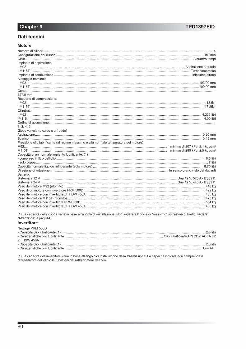
Chapter 9 TPD1397EID
80
Dati tecniciMotoreNumero di cilindri .........................................................................................................................................................................................4Configurazione dei cilindri ................................................................................................................................................................. In lineaCiclo.......................................................................................................................................................................................A quattro tempiImpianto di aspirazione:- M92 ............................................................................................................................................................................ Aspirazione naturale- M115T .............................................................................................................................................................................. TurbocompressoImpianto di combustione.......................................................................................................................................................Iniezione direttaAlesaggio nominale:- M92 ...........................................................................................................................................................................................103,00 mm- M115T .......................................................................................................................................................................................100,00 mmCorsa ............................................................................................................................................................................................................. 127,0 mmRapporto di compressione:- M92 ...................................................................................................................................................................................................18,5:1- M115T .............................................................................................................................................................................................17,25:1Cilindrata- M92 .............................................................................................................................................................................................. 4,233 litri-M115 ................................................................................................................................................................................................ 4,00 litriOrdine di accensione ..................................................................................................................................................................................... 1, 3, 4, 2Gioco valvole (a caldo o a freddo)Aspirazione ......................................................................................................................................................................................0,20 mmScarico.............................................................................................................................................................................................0,45 mmPressione olio lubrificante (al regime massimo e alla normale temperatura del motore)M92..........................................................................................................................................................un minimo di 207 kPa, 2,1 kgf/cm2
M115T ......................................................................................................................................................un minimo di 280 kPa, 2,5 kgf/cm2
Capacità di un normale impianto lubrificante: (1)- compreso il filtro dell’olio .................................................................................................................................................................. 8,5 litri- solo coppa ........................................................................................................................................................................................... 7 litriCapacità normale liquido refrigerante (solo motore) ........................................................................................................................ 8,75 litriDirezione di rotazione ................................................................................................................................. In senso orario visto dal davantiBatteria:Sistema a 12 V .....................................................................................................................................................Una 12 V, 520 A - BS3911Sistema a 24 V .....................................................................................................................................................Due 12 V, 440 A - BS3911Peso del motore M92 (rifornito) .......................................................................................................................................................... 418 kgPeso di un motore con invertitore PRM 500D ................................................................................................................................... 499 kgPeso del motore con invertitore ZF HSW 450A ................................................................................................................................. 455 kgPeso del motore M115T (rifornito) ...................................................................................................................................................... 423 kgPeso del motore con invertitore PRM 500D ...................................................................................................................................... 504 kgPeso del motore con invertitore ZF HSW 450A ................................................................................................................................. 460 kg
(1) La capacità della coppa varia in base all’angolo di installazione. Non superare l’indice di “massimo” sull’astina di livello, vedere “Attenzione” a pag. 44.InvertitoreNewage PRM 500D- Capacità olio lubrificante (1) ............................................................................................................................................................ 2,5 litri- Caratteristiche olio lubrificante ........................................................................................................... Olio lubrificante API CD o ACEA E2ZF HSW 450A- Capacità olio lubrificante (1) ............................................................................................................................................................ 2,0 litri- Caratteristiche olio lubrificante ...................................................................................................................................................... Olio ATF
(1) La capacità dell’invertitore varia in base all’angolo di installazione della trasmissione. La capacità indicata non comprende il raffreddatore dell’olio o le tubazioni del raffreddatore dell’olio.

TPD1397EID Chapter 9
81
Algemene gegevensMotorAantal cilinders ............................................................................................................................................................................................4Cilinderopstelling ...................................................................................................................................................................................In lijnMotorcyclus .......................................................................................................................................................................................ViertaktInlaatsysteem:- M92 .....................................................................................................................................................................................Niet opgeladen- M115T .......................................................................................................................................................................Met turbocompressorVerbrandingssysteem ........................................................................................................................................................ Directe inspuitingNominale boring- M92 ...........................................................................................................................................................................103,00 mm (4,055 in)- M115T .......................................................................................................................................................................100,00 mm (3,937 in)Slag ............................................................................................................................................................................................................... 127,0 mm (5,00 in)Compressieverhouding:- M92 ...................................................................................................................................................................................................18.5:1- M115T .............................................................................................................................................................................................17.25:1Cilinderinhoud- M92 ...............................................................................................................................................................................4,233 l (258,00 in3)-M115 .................................................................................................................................................................................4,00 l (243,00 in3)Ontstekingsvolgorde ...................................................................................................................................................................................... 1, 3, 4, 2Klepspeling (heet of koud):Inlaat ................................................................................................................................................................................0,20 mm (0,008 in)Uitlaat ..............................................................................................................................................................................0,45 mm (0,018 in)Smeeroliedruk (minimum bij maximum motortoerental en normale motortemperatuur)M92........................................................................................................................................... mindestens 207 kPa (30 lbf/in2) 2,1 kgf/cm2
M115T ....................................................................................................................................... mindestens 280 kPa (40 lbf/in2) 2,5 kgf/cm2
Inhoud van een kenmerkend oliesysteem: (1)- inclusief oliefilter ................................................................................................................................................................ 8,5 l (16,5 pints)- alleen carter.......................................................................................................................................................................... 7 l (15,8 pints)Nominale benodigde hoeveelheid koelvloeistof (alleen motor) ......................................................................................... 8,75 l (15,4 pints)Draairichting ......................................................................................................................................... Met de klok mee vanaf de voorzijdeAccu:12 V-systeem ............................................................................................................................................Een 12 V, 520 A conform BS391124 V systeem ..........................................................................................................................................Twee 12 V, 440 A conform BS3911Gewicht van de motor (met vloeistoffen) 263 kg ...................................................................................................................418 kg (921 lb)Gewicht van motor met een PRM 500D keerkoppeling....................................................................................................... 499 kg (1100 lb)Gewicht van motor met een ZF HSW 450A keerkoppeling .................................................................................................455 kg (1003 lb)Gewicht van motor M115T (met vloeistoffen) .........................................................................................................................423 kg (933lb)Gewicht van motor met een PRM 500D keerkoppeling........................................................................................................504 kg (1111 lb)Gewicht van motor met een ZF HSW 450A keerkoppeling .................................................................................................460 kg (1014 lb)
(1) De carterinhoud hangt af van de installatiehoek. Niet verder bijvullen dan tot aan het “vol”-merkteken op de peilstok, zie “Voorzicht” op pagina 44.KeerkoppelingNewage PRM 500D- Benodigde hoeveelheid smeerolie (1) .............................................................................................................................. 2,5 l (4.40 pints) - Oliespecificatie ................................................................................................................................. Motorsmeerolie API CD of ACEA E2ZF HSW 450A- Benodigde hoeveelheid smeerolie (1) ................................................................................................................................2,0 (3,52 pints) - Oliespecificatie ..............................................................................................................................................................................ATF olie
(1) De keerkoppelinginhoud hangt af van de installatiehoek van de transmissie. De vermelde hoeveelheden olie zijn exclusief de oliekoeler en de leidingen.

Chapter 9 TPD1397EID
82

California
Proposition 65 Warning
Diesel engine exhaust and some of its constituents are known to the State of California to cause cancer, birth
defects, and other reproductive harm.

All information in this document is substantially correct at time of printing and may be altered subsequently. Part No. TPD 1397EID issue 9Produced in England ©2013 by Wimborne Marine Power Centre
Wimborne Marine Power Centre22 Cobham Road, Ferndown Industrial Estate, Wimborne, Dorset, BH21 7PW, England.Tel: +44 (0)1202 796000, Fax: +44 (0)1202 796001E-mail: [email protected]
Web: www.perkins.com/Marine