Embed Size (px)
Citation preview

User's Guide TD-4420TN/4520TN
TD-4420TN/4520TN User's Guide (English)
© 2019 Brother Industries, Ltd. All rights reserved.Version 01
ENG

i
Copyright Information
The copyright in this manual, the software, and firmware in the printer described therein are owned by Brother. All rights reserved. CG Triumvirate is a trademark of Agfa Corporation. CG Triumvirate Bold Condensed font is under license from the Monotype Corporation. All other trademarks are the property of their respective owners. Any trade names and product names of companies appearing on Brother products, related documents and any other materials are all trademarks or registered trademarks of those respective companies.
Information in this document is subject to change without notice and does not represent a commitment on the part of the company. No part of this manual may be reproduced or transmitted in any form or by any means, for any purpose other than the purchaser’s personal use, without the expressed written permission of the company.

ii
Contents 1. Introduction ............................................................................................................ 1
1.1 Product Introduction ......................................................................................... 1
1.2 Product Features .............................................................................................. 2
1.2.1 Standard Features ............................................................................... 2
1.2.2 Optional Features ................................................................................ 3
1.3 General Specifications ..................................................................................... 3
1.4 Print Specifications ........................................................................................... 3
1.5 Ribbon Specifications ....................................................................................... 4
1.6 Media Specifications ........................................................................................ 4
2. Operations Overview .............................................................................................. 5
2.1 Unpack the printer and check the components ................................................ 5
2.2 Printer Overview ............................................................................................... 6
2.2.1 Front View ............................................................................................ 6
2.2.2 Interior View ......................................................................................... 7
2.2.3 Rear View ............................................................................................ 8
3. Setup ...................................................................................................................... 9
3.1 Setting up the Printer ........................................................................................ 9
3.2 Loading the Ribbon ........................................................................................ 10
3.3 Loading the Media .......................................................................................... 14
3.3.1 Loading the Label Rolls ..................................................................... 14
3.3.2 External Label Roll Mount Installation (Optional) ............................... 18
3.3.3 Loading the Media in Cutter mode (Dealers only) ............................. 20
3.3.4 Loading the Media in Peel-off Mode (Dealers only) ........................... 22
4. The LED Indicator and Feed/Pause Button Functions ......................................... 25
4.1 The LED Indicator .......................................................................................... 25
4.2 The Feed/Pause Button Functions ................................................................. 25
4.3 Power-on Utilities ........................................................................................... 25
4.3.1 Ribbon and Gap/Black Mark Sensors Calibration .............................. 26
4.3.2 Gap/Black Mark Sensor Calibration, Self-Test, and Entering Dump Mode .................................................................................................. 27
4.3.3 Printer Initialization ............................................................................. 30
4.3.4 Media Sensor Calibration (For the Black Mark Sensor) ..................... 31
4.3.5 Media Sensor Calibration (For the Gap Sensor) ................................ 32
4.3.6 Skip the AUTO.BAS program ............................................................ 32

iii
5. BPM (Brother Printer Management Tool) ............................................................. 33
5.1 Start the BPM ................................................................................................. 33
5.2 Printer Function .............................................................................................. 34
5.3 Calibrating the Media Sensor using the BPM ................................................. 35
5.3.1 Auto Calibration ................................................................................. 35
6. Troubleshooting ................................................................................................... 36
7. Maintenance ......................................................................................................... 38

1
1. Introduction
1.1 Product Introduction The sleek design of the TD-4420TN/4520TN label printer can handle up to 984 ft. (300 m) of ribbon and label rolls. Its internal 5” (127 mm) label capacity can be further expanded with an external label roll mount to handle 8” (203.2 mm) rolls, designed for industrial label printers. The printer's movable Black Mark Sensor is compatible with a wide range of label media. The printer uses its high-performance, high-quality, built-in Monotype Imaging® TrueType font engine with the CG Triumvirate Bold Condensed smooth scalable font. It also provides a choice of eight different sizes of the alphanumeric bitmap font. The printer's flexible firmware design allows the user to download additional TrueType fonts from a computer to print custom labels. It also supports most of the standard barcode formats and can print fonts and barcodes in four directions.
• For more information about printing labels, see your labelling software's documentation. • For more information about writing custom programs, see the FBPL Command Reference
Manual.

2
1.2 Product Features 1.2.1 Standard Features
Thermal transfer printing Direct thermal printing Gap Sensor Fully movable reflective Black Mark Sensor Ribbon Sensor Head Open Sensor USB 2.0 (Hi-Speed) 64 MB DRAM memory 128 MB Flash memory RTC BUZZER Feed/Pause Button Three-color LED Indicator Standard industry emulation (including the Eltron® and Zebra® languages) 8 built-in alphanumeric bitmap fonts Fonts and barcodes can be printed in four directions (0°, 90°, 180°, 270°) Internal Monotype Imaging® TrueType font engine with CG Triumvirate Bold Condensed
scalable font Downloadable fonts (from a computer) Downloadable firmware upgrades Text, barcode, graphics/image printing (See the FBPL Command Reference Manual for
the supported codes.) Supported barcodes 1D barcodes
Code128UCC, Code128 subsets A/B/C, EAN128, Interleaved 2 of 5, Interleaved 2 of 5 with check digit, Code39, Code39 with check digit, Code93, EAN13, EAN8, UPCA, UPCE, EAN and UPC 2 (5) digits add-on, Codabar, Postnet, MSI, MSI with check digit, PLESSEY, China Post, ITF14, Code11, TELEPEN, TELEPENN, PLANET, Code49, Deutsche Post Identcode, Deutsche Post Leitcode, LOGMARS
2D barcodes GS1 DataBar, GS1 DataMatrix, Maxicode, AZTEC, PDF417, QR Code, Micro PDF 417
Supported image formats BITMAP, BMP, PCX (Max. 256 colors graphics) Supported Protocols Ethernet ARP, MAC, BOOTP, DHCP, DNS, WINS, FTP SERVER, HTTP server, SNTP client, SMTP client, SNMP V1, Telnet, LPR/LPD, RAW 9100, IPV4, ICMP, IGMP, TCP, UDP

3
1.2.2 Optional Features
Feature User Dealer External Media Roll Mount with 3” (76.2 mm) Core Label Spindle (8.4” (213.4 mm) outer diameter)
Label Peeler
Regular Full/Partial Cutter (Guillotine cutter) Paper thickness: From 2.36 mil to 7.48 mil (from 0.06 mm to 0.19 mm)
1.3 General Specifications Dimensions 8.03” (W) × 6.99” (H) × 11.02” (L) (204 mm (W) × 177.5 mm (H) × 280 mm (L))
Weight 2.5 kg
Power Supply Input: AC 100 V - 240 V, 1.5 A, 50 Hz - 60 Hz Output: DC 24 V, 2.5 A, 60 W, LPS
Environment Operating temperature: Between 41˚F and 104˚F (between 5˚C and 40˚C) Operating humidity: Between 25% and 85% (without condensation) Storage temperature: Between -40˚F and 140˚F (between -40˚C and 60˚C) Storage humidity: Between 10% and 90% (without condensation)
1.4 Print Specifications
Print Specifications TD-4420TN
(203 dpi model) TD-4520TN
(300 dpi model) Print Resolution 203 dots/inch
(8 dots/mm) 300 dots/inch (12 dots/mm)
Printing Technology Thermal transfer and direct thermal
Print Size (width × length)
0.125 mm × 0.125 mm (1 mm = 8 dots)
0.084 mm × 0.084 mm (1 mm = 11.8 dots)
Print Speed (inches per second)
Up to 6 ips Up to 5 ips
Print Speed for Label Peeler Mode Up to 3 ips
Maximum Print Width 4.25” (108 mm) 4.16” (105.7 mm)
Maximum Print Length 1000” (25,400 mm) 450” (11,430 mm)
4
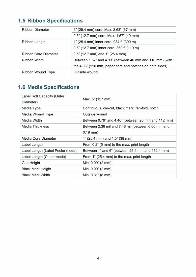
1.5 Ribbon Specifications Ribbon Diameter 1” (25.4 mm) core: Max. 2.63” (67 mm)
0.5” (12.7 mm) core: Max. 1.57” (40 mm)
Ribbon Length 1” (25.4 mm) inner core: 984 ft (300 m)
0.5” (12.7 mm) inner core: 360 ft (110 m)
Ribbon Core Diameter 0.5” (12.7 mm) and 1” (25.4 mm)
Ribbon Width Between 1.57” and 4.33” (between 40 mm and 110 mm) (with the 4.33” (110 mm) paper core and notches on both sides)
Ribbon Wound Type Outside wound
1.6 Media Specifications Label Roll Capacity (Outer Diameter)
Max. 5” (127 mm)
Media Type Continuous, die-cut, black mark, fan-fold, notch
Media Wound Type Outside wound
Media Width Between 0.79” and 4.40” (between 20 mm and 112 mm)
Media Thickness Between 2.36 mil and 7.48 mil (between 0.06 mm and 0.19 mm)
Media Core Diameter 1” (25.4 mm) and 1.5” (38 mm)
Label Length From 0.2” (5 mm) to the max. print length
Label Length (Label Peeler mode) Between 1” and 6” (between 25.4 mm and 152.4 mm)
Label Length (Cutter mode) From 1” (25.4 mm) to the max. print length
Gap Height Min. 0.09” (2 mm)
Black Mark Height Min. 0.09” (2 mm)
Black Mark Width Min. 0.31” (8 mm)

5
2. Operations Overview
2.1 Unpack the printer and check the components Note
Keep the packaging materials in case you need to ship the printer.
The components included in the box:
1. Printer Unit
2. 1” (25.4 mm) Ribbon Paper Core
3. Two 1” (25.4 mm) Ribbon Spindles for the 984 ft (300 m) ribbon
4. Power Cord
5. External Universal Switching Power Supply
6. USB Interface Cable
7. Quick Setup Guide
If any components are missing, contact the product manufacturer's customer service or your local dealer.
1
2 3 4 5 6 7

6
2.2 Printer Overview
2.2.1 Front View
1. LED Indicator 2. Feed/Pause Button 3. Roll Compartment Cover Open Tab 4. Label Output Slot
1
2
4
3

7
2.2.2 Interior View
1. Roll Compartment Cover 8. Platen Roller 2. Ribbon Supply Spindle 9. Black Mark Sensor 3. Ribbon Supply Hub 10. Gap Sensor 4. Ribbon Rewind Hub 11. Media Guide Tips 5. Ribbon Rewind Spindle 12. Media Guide Hub 6. Print Head Release Button 13. Print Head 7. Roll Guides
WARNING
DO NOT touch rotating parts. There is a risk of injury if your finger is caught in the rotating gear. Turn off the product before touching the mechanism.
7
4
5 12
11
2 3
OPEN
1
6
8
13
10
9
11

8
2.2.3 Rear View
1. Power Switch 2. Power Port 3. USB Port (USB 2.0/Hi-Speed mode) 4. USB Host Port 5. RS-232 Serial Port 6. Ethernet Port
Note Some features are not available depending on the model. For more information, see the product specification.
1 2 3 6 5 4

9
3. Setup
3.1 Setting up the Printer Note Before you plug the Power Cord into the Power Port, make sure the printer's Power Switch
is in the OFF position. Some features are not available depending on the model. For more information, see the
product specification.
1. Place the printer on a flat, secure surface. 2. Plug the Power Cord into the Power Port at the rear of the printer. Then, plug the other end
into the AC power outlet (electrical socket). 3. Connect the printer to the computer with the provided USB cable. 4. Push the “-” side of the Power Switch to turn on the printer.
10
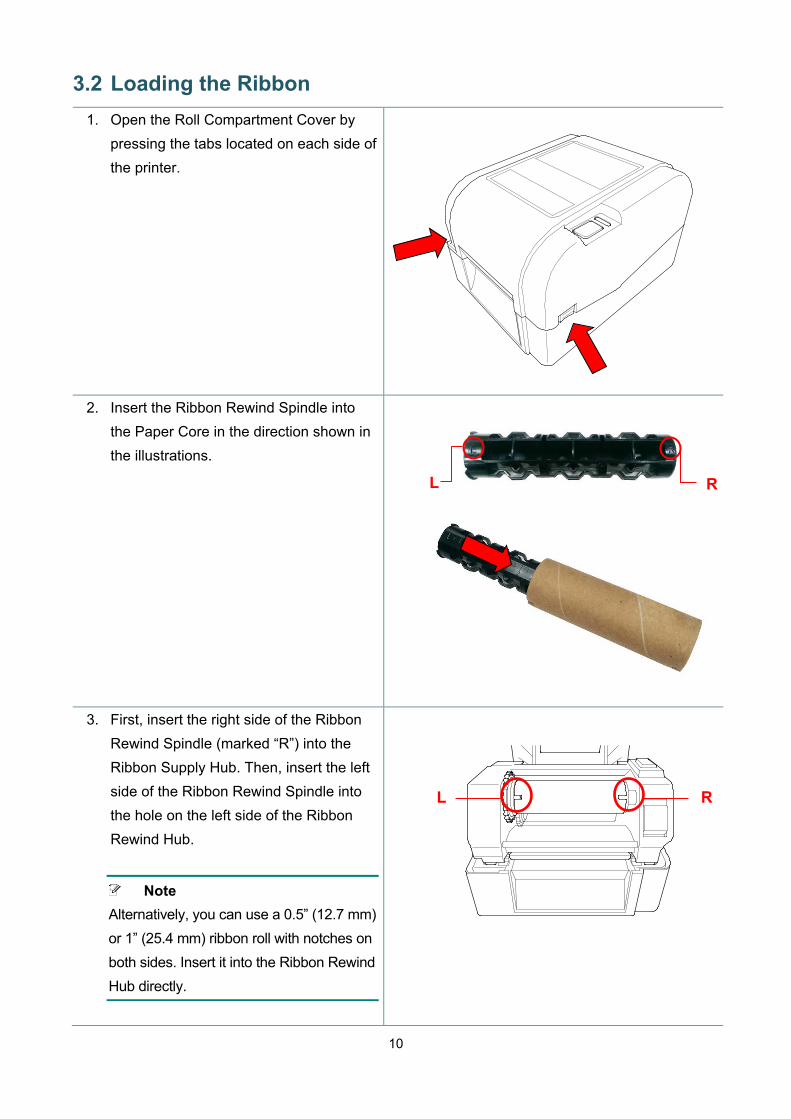
3.2 Loading the Ribbon 1. Open the Roll Compartment Cover by
pressing the tabs located on each side of the printer.
2. Insert the Ribbon Rewind Spindle into the Paper Core in the direction shown in the illustrations.
3. First, insert the right side of the Ribbon Rewind Spindle (marked “R”) into the Ribbon Supply Hub. Then, insert the left side of the Ribbon Rewind Spindle into the hole on the left side of the Ribbon Rewind Hub.
Note Alternatively, you can use a 0.5” (12.7 mm) or 1” (25.4 mm) ribbon roll with notches on both sides. Insert it into the Ribbon Rewind Hub directly.
R L
L R

11
4. Push the Print Head Release Button to open the Print Head mechanism.
5. Lift the Print Head until it locks into place.
6. Insert the Ribbon Spindle into the ribbon.
Note The Ribbon Spindle can be substituted with the ribbon with notches on both sides, which can be inserted into the ribbon mechanism directly.
L
Interior View
12
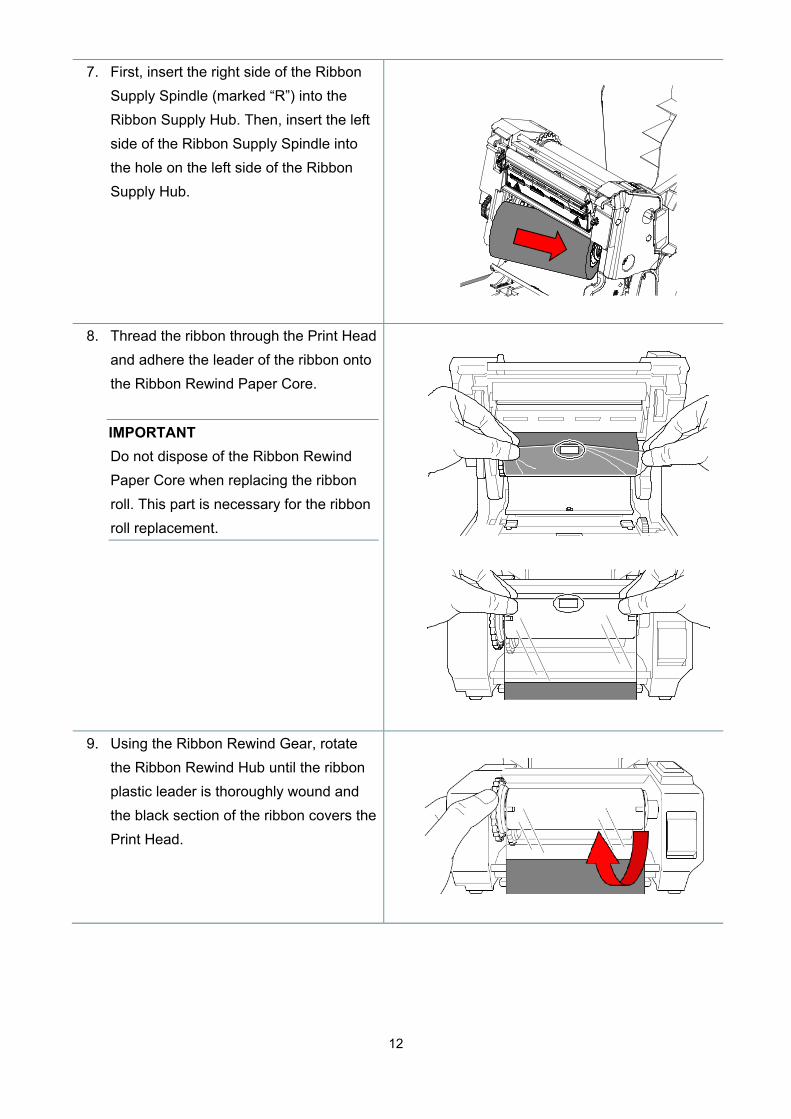
7. First, insert the right side of the Ribbon Supply Spindle (marked “R”) into the Ribbon Supply Hub. Then, insert the left side of the Ribbon Supply Spindle into the hole on the left side of the Ribbon Supply Hub.
8. Thread the ribbon through the Print Head and adhere the leader of the ribbon onto the Ribbon Rewind Paper Core.
IMPORTANT Do not dispose of the Ribbon Rewind Paper Core when replacing the ribbon roll. This part is necessary for the ribbon roll replacement.
9. Using the Ribbon Rewind Gear, rotate the Ribbon Rewind Hub until the ribbon plastic leader is thoroughly wound and the black section of the ribbon covers the Print Head.

13
10. Close the Print Head mechanism with both hands until it locks into place.
Ribbon Loading Path 1. Print Head 2. Ribbon Rewind Gear 3. Media Guide Tips 4. Platen Roller 5. Black Mark Sensor 6. Gap Sensor 7. Ribbon
1
7
6
3
4
2
5

14
3.3 Loading the Media 3.3.1 Loading the Label Rolls
1. Open the Roll Compartment Cover by pressing the tabs located on each side of the printer.
2. Push up the lock switch to unlock the Roll Guides. Slide both Roll Guides outwards.
3. Insert the paper roll with the labels facing up, as shown in the illustration. Push down the lock switch to lock the Roll Guides into place.
Note Make sure that the label print side is facing up.

15
4. Push the Print Head Release Button to open the Print Head mechanism.
5. Thread the labels under the Print Head mechanism and feed the paper through the Label Output Slot. Position the end of the paper slightly out of the Label Output Slot.
Note
The Black Mark Sensor is moveable and the Gap Sensor is fixed. Make sure you align the Black Mark Sensor Slider with the installed media and that the position of the media's gap/black mark is aligned with the Gap Sensor.
6. Adjust the Media Guide Tips to fit the
label width.
Media Guide Tips
Platen Roller
Gap Sensor
Black Mark Sensor

16
7. Close the Print Head mechanism with both hands until it locks into place.
8. Use the Brother Printer Management
Tool to set the media sensor type and calibrate the selected sensor.
a. Start the BPM. b. Click the Printer Function button. c. Click the Calibrate button. For more information about sensor calibration, see section 5.3.
Note Calibrate the Gap/Black Mark Sensor every time you change the media.
17
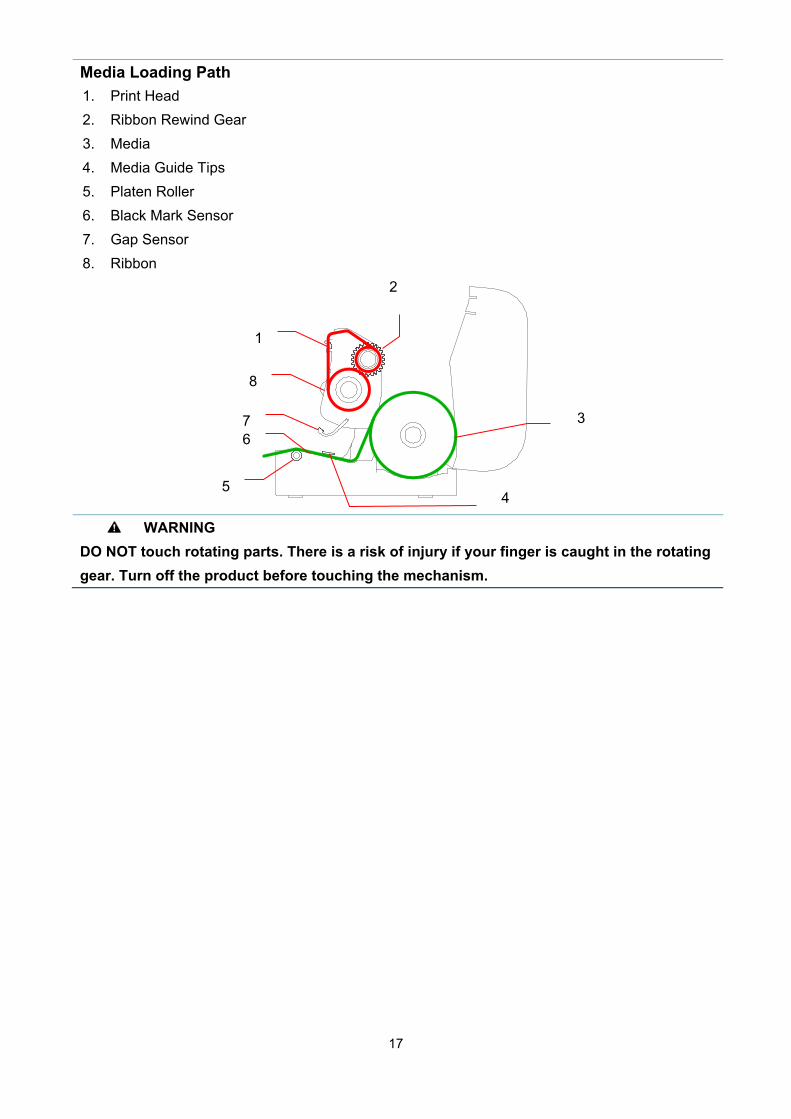
Media Loading Path 1. Print Head 2. Ribbon Rewind Gear 3. Media 4. Media Guide Tips 5. Platen Roller 6. Black Mark Sensor 7. Gap Sensor 8. Ribbon
WARNING
DO NOT touch rotating parts. There is a risk of injury if your finger is caught in the rotating gear. Turn off the product before touching the mechanism.
2
1
3
4 5
6 7
8

18
3.3.2 External Label Roll Mount Installation (Optional)
1. Tighten the screws on the metal fittings of the extended plate.
2. Attach the extended plate to the bottom
of the printer.
3. Insert a 3” (76.2 mm) Label Spindle into a paper roll. Then, install it on the External Paper Roll Mount.
3” (76.2 mm) Label Spindle

19
4. Feed the media through the rear label feed slot.
Note Make sure that the label print side is facing up.
5. Open the Roll Compartment Cover. Slide the Roll Guides outwards, and then align the paper width with the Roll Guides. Push down the lock switch to lock the Roll Guide.
6. Install the label roll as described in section 3.3.1.
7. Turn the Media Guide Hub, and match the Media Guide width to the paper width.
8. Use the Brother Printer Management Tool to set the media sensor type and calibrate the selected sensor.
Note Calibrate the Gap/Black Mark Sensor every time you change the media.

20
3.3.3 Loading the Media in Cutter mode (Dealers only)
1. Install the label roll as described in section 3.3.1.
2. Use the Brother Printer Management Tool to set the media sensor type and calibrate the selected sensor.
3. Open the Roll Compartment Cover by pressing the tabs located on each side of the printer.
4. Push the Print Head Release Button to open the Print Head mechanism and feed the media through the media sensor. Adjust the Media Guide Tips to fit the label width.
5. Push the media through the Cutter Output Slot.
Note Make sure that the label print side is facing up.
Media Guide Tips

21
6. Close the Print Head mechanism with both hands until it locks into place.
7. Close the Roll Compartment Cover. 8. Use the Brother Printer Management Tool to set the printer for cutter mode.
a. Start the BPM. b. Click the Printer Configuration button. c. Select the FBPL tab. d. Select the CUTTER option from the Post-Print Action drop-down list. e. Click Set.
f. Press the Feed/Pause Button to test.
Feed/Pause Button

22
Note Calibrate the Gap/Black Mark Sensor every time you change the installed media.
3.3.4 Loading the Media in Peel-off Mode (Dealers only)
1. Install the label roll as described in section 3.3.1.
2. Use the Brother Printer Management Tool to set the media sensor type and calibrate the selected sensor.
3. Open the Roll Compartment Cover by pressing the tabs located on each side of the printer.
4. Push the Print Head Release Button to open the Print Head mechanism and feed the media through the media sensor. Adjust the Media Guide Tips to fit the label width.
5. Pull the media out of the printer and remove some labels, leaving the liner only.
Note Make sure that the label print side is facing up.
Media Guide Tips
Liner
Label

23
6. Open the Label Peeler Cover. Feed the liner into Label Peeler Cover Slot.
7. Close the Label Peeler Module.
8. Use the Brother Printer Management Tool to set the Label Peeler mode. a. Start the BPM. b. Click the Printer Configuration button. c. Select the FBPL tab. d. Select the PEEL option from the Post-Print Action drop-down list. e. Click Set.
Label Peeler Cover Slot

24
9. Close the Roll Compartment Cover.
Note The Label Peeler Module supports only plain paper.

25
4. The LED Indicator and Feed/Pause Button
Functions
By using the printer's Feed/Pause Button and the three-color LED Indicator, you can feed labels, pause print jobs, select and calibrate sensors, print the printer self-test report, and restore the printer's factory settings.
4.1 The LED Indicator LED Color Description
Green (Lit) The power is on and the printer is ready to use.
Green (Flashing) The printer is downloading data from a computer.
The printer is paused.
Amber The printer removes data.
Red (Lit) The Print Head is open.
There is a problem with the Cutter.
Red (Flashing) There is a memory error or printing error (for example: paper
jam, Print Head is open, paper is empty, or the ribbon is
empty).
4.2 The Feed/Pause Button Functions 1. Feed Labels To feed a label, press the Feed/Pause Button when the printer's LED is lit in green. 2. Pause Print Jobs To pause a print job, press the Feed/Pause Button. The LED flashes in green. To resume the print job, press the button again.
4.3 Power-on Utilities There are six power-on utilities to set up and test the printer's functions. To activate a power-on utility: 1. Turn off the printer. 2. Press and hold the Feed/Pause Button, and then turn on the printer. 3. Release the button when the LED indicates the function you want:

26
Power-On Utility LED Patterns
LED color
Function
Amber Red
(5 times)
Amber
(5 times)
Green
(5 times)
Green/Amber
(5 times)
Red/Amber
(5 times)
Green (Lit)
1. Ribbon and Gap/Black Mark Sensors
calibration
2. Gap/Black Mark Sensor calibration,
self-test, and entering dump mode
3. Printer initialization
4. Media sensor calibration (For the Black
Mark Sensor)
5. Media sensor calibration (For the Gap
Sensor)
6. Skip the AUTO.BAS program
4.3.1 Ribbon and Gap/Black Mark Sensors Calibration
The Gap/Black Mark Sensor sensitivity should be calibrated when: A new printer is purchased Label stock is changed Printer initialization takes place
To calibrate the ribbon and Gap/Black Mark Sensors: 1. Turn off the printer. 2. Press and hold the Feed/Pause Button, and then turn on the printer. 3. Release the button when the LED is flashing in red.
Note The LED color will change as follows:
Amber red (5 times) amber (5 times) green (5 times) green/amber (5 times) red/amber (5 times) green (lit)
To select the sensor for calibration, send the correct command to the printer: For the Gap Sensor: send the GAP command For the Black Mark Sensor: send the BLINE command For more information about the available commands, see the FBPL Command Reference Manual.

27
4.3.2 Gap/Black Mark Sensor Calibration, Self-Test, and Entering Dump Mode
During the calibration of the Gap/Black Mark Sensor, the printer will detect the label length, print the internal configuration (self-test), and then enter the dump mode. Calibrate the Gap or Black Mark Sensor if the sensor's settings used in the last print job are not suitable for the current print job. To calibrate the Gap/Black Mark Sensor: 1. Turn off the printer. 2. Press and hold the Feed/Pause Button, and then turn on the printer. 3. Release the button when the LED is flashing in amber.
Note The LED color will change as follows: Amber red (5 times) amber (5 times) green (5 times) green/amber (5 times) red/amber (5 times) green (lit)
4. The printer calibrates the sensor and detects the label length, prints the internal settings, and
then enters the dump mode.
Note To select the sensor for calibration, send the correct command to the printer: For the Gap Sensor: send the GAP command For the Black Mark Sensor: send the BLINE command For more information about the available commands, see the FBPL Command Reference Manual.

28
Self-test You can print the printer configuration after the Gap/Black Mark Sensor calibration. Self-test printouts list the printer's configuration and available memory space, and can indicate whether there is any dot damage on the heater component.
Self-test printout
Model name Firmware version Firmware checksum Printer serial number Configuration file System date System time Printed mileage (meter) Cutting counter Number of defective dots
Print speed (inch/sec) Print density Label size (inch) Gap distance (inch) Gap/Black Mark Sensor sensitivity Code page Country code
Print darkness Print speed (inch/sec) Label size Control prefix Format prefix Delimiter prefix Printer power up motion Print Head close motion
RS232 Serial Port configuration

29
Printer name Mac Address DHCP IP Address Subnet Mask Gateway RAW Port
Number of downloaded files Total and available memory space Print Head check pattern

30
Dump mode The printer will enter dump mode after printing the printer configuration. This mode allows users to verify and debug the printer's programs. The characters in the left column are received from the printer's system and those in the right column are their hexadecimal representation.
Note Dump mode requires 4” (101.5 mm) wide paper. To resume normal printing, turn the printer off and then on again.
4.3.3 Printer Initialization
Printer initialization clears the printer's DRAM and restores its factory settings. To activate printer initialization: 1. Turn off the printer. 2. Press and hold the Feed/Pause Button, and then turn on the printer. 3. Release the button after the amber LED flashes five times and the LED is lit in green.
Note The LED color will change as follows: Amber red (5 times) amber (5 times) green (5 times) green/amber (5 times) red/amber (5 times) green (lit)
ASCII data Hexadecimal representation of the ASCII data
31
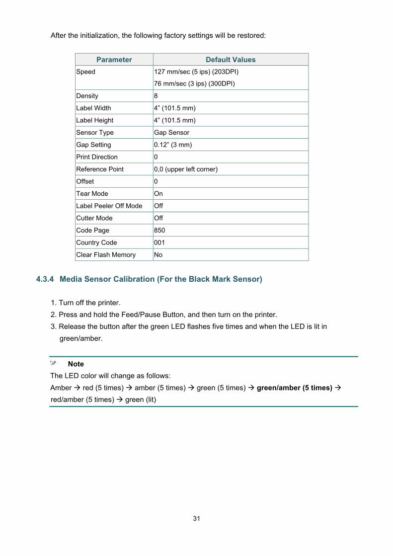
After the initialization, the following factory settings will be restored:
Parameter Default Values Speed 127 mm/sec (5 ips) (203DPI)
76 mm/sec (3 ips) (300DPI)
Density 8
Label Width 4” (101.5 mm)
Label Height 4” (101.5 mm)
Sensor Type Gap Sensor
Gap Setting 0.12” (3 mm)
Print Direction 0
Reference Point 0,0 (upper left corner)
Offset 0
Tear Mode On
Label Peeler Off Mode Off
Cutter Mode Off
Code Page 850
Country Code 001
Clear Flash Memory No
4.3.4 Media Sensor Calibration (For the Black Mark Sensor)
1. Turn off the printer. 2. Press and hold the Feed/Pause Button, and then turn on the printer. 3. Release the button after the green LED flashes five times and when the LED is lit in
green/amber.
Note The LED color will change as follows: Amber red (5 times) amber (5 times) green (5 times) green/amber (5 times) red/amber (5 times) green (lit)

32
4.3.5 Media Sensor Calibration (For the Gap Sensor)
1. Turn off the printer. 2. Press and hold the Feed/Pause Button, and then turn on the printer. 3. Release the button after the green/amber LED flashes five times and the LED is lit in
red/amber.
Note The LED color will change as follows: Amber red (5 times) amber (5 times) green (5 times) green/amber (5 times) red/amber (5 times) green (lit)
4.3.6 Skip the AUTO.BAS program
The user can upload the AUTO.BAS program to the printer's flash memory so that it can be run automatically at startup. To prevent the AUTO.BAS program from running at startup: 1. Turn off the printer. 2. Press the Feed/Pause Button, and then turn on the printer. 3. Release the button when the LED is lit in green.
Note The LED color will change in the following order: Amber red (5 times) amber (5 times) green (5 times) green/amber (5 times) red/amber (5 times) green (lit)
4. The printer will start without running the AUTO.BAS program.

33
5. BPM (Brother Printer Management Tool)
The Brother Printer Management Tool is an integrated tool allowing you to: Check a printer’s status and settings. Change printer settings. Send additional commands to a printer. Download graphics and fonts. Create a printer bitmap font. Download and update firmware. Using this tool, you can also review your printer's status and settings to troubleshoot any problems.
5.1 Start the BPM
1. Double-click the BPM icon to start the software.
BPM's main screen allows you to access the following options: Printer Configuration File Manager Command Tool RTC Setup Printer Function Bitmap Font Manager For more information, see the Brother Printer Management Tool Quick Start Guide.
Features
buttons
Interface
type
Printer
status
Configuration
buttons
34
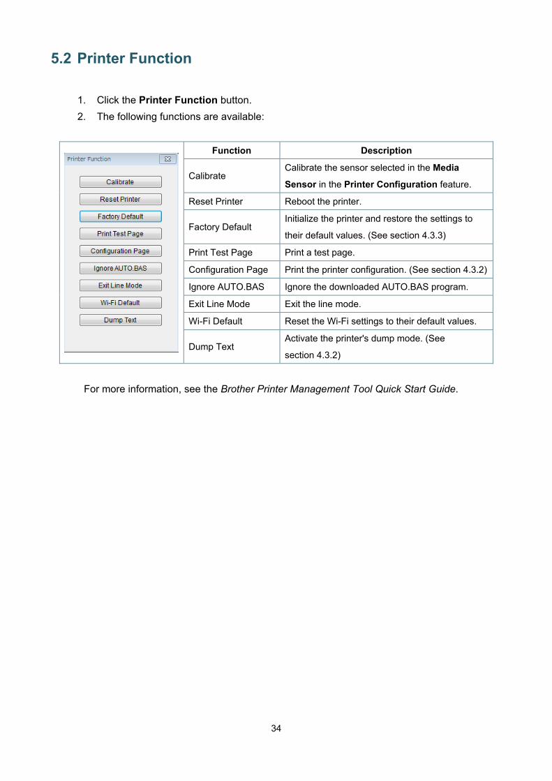
5.2 Printer Function 1. Click the Printer Function button. 2. The following functions are available:
Function Description
Calibrate Calibrate the sensor selected in the Media
Sensor in the Printer Configuration feature.
Reset Printer Reboot the printer.
Factory Default Initialize the printer and restore the settings to
their default values. (See section 4.3.3)
Print Test Page Print a test page.
Configuration Page Print the printer configuration. (See section 4.3.2)
Ignore AUTO.BAS Ignore the downloaded AUTO.BAS program.
Exit Line Mode Exit the line mode.
Wi-Fi Default Reset the Wi-Fi settings to their default values.
Dump Text Activate the printer's dump mode. (See
section 4.3.2)
For more information, see the Brother Printer Management Tool Quick Start Guide.

35
5.3 Calibrating the Media Sensor using the BPM 5.3.1 Auto Calibration
Use the BPM to set the media sensor type (Gap Sensor or Black Mark Sensor) and calibrate the selected sensor.
Gap Sensor Black Mark Sensor
The transmissive/gap sensor detects the beginning of the label and feeds the label to the correct position. The reflective/black mark sensor detects the mark and feeds the media to the correct position.
1. Make sure the media is already installed and the Print Head mechanism is closed.
(See section 3.3) 2. Turn on the printer. 3. Start the BPM. 4. Click the Printer Function button. 5. Click the Calibrate button. 6. Select the sensor media type and click Calibrate.

36
6. Troubleshooting
This chapter explains how to resolve typical problems you may encounter when using the printer. If you have any problems with the printer, first make sure you have performed the following tasks correctly. If you still have problems, contact the product manufacturer's customer service or your local dealer.
Problem Possible Cause Solution
The LED Indicator is not lit. The Power Cord is not correctly connected.
Make sure the printer is correctly connected to the power outlet (electrical socket) using the Power Cord.
Turn the printer on.
- The Brother Printer Management Tool shows Head Open.
- The LED flashes in red.
The Print Head mechanism is open. Close the Print Head mechanism.
- The Brother Printer Management Tool shows Out of Ribbon or Ribbon Encoder Err.
- The LED flashes in red.
The ribbon has run out. The ribbon is installed
incorrectly.
Install a new ribbon roll. To install a new ribbon roll, see
section 3.2.
- The Brother Printer Management Tool shows Out of Paper.
- The LED flashes in red.
The label has run out. The label is installed
incorrectly. The Gap/Black Mark Sensor
is not calibrated.
Install a new label roll. To install a new label roll, see section 3.3. Calibrate the Gap/Black Mark Sensor.
- The Brother Printer Management Tool shows Paper Jam.
- The LED flashes in red.
The Gap/Black Mark Sensor is not calibrated.
Make sure label size is set correctly.
Labels may be stuck inside the Printer Head mechanism.
Calibrate the Gap/Black Mark Sensor. Set the label size correctly.
I cannot print.
The cable is not connected to the serial or USB interface.
The serial port cable is not correctly connected.
Re-connect the serial or USB cable. Try a new cable. Use a correct ribbon or media. Check the ribbon for damage. Reinstall the ribbon. Clean the Print Head. Adjust the print density and print speed. The Print Head's harness connector is not
connected correctly with the Print Head. Turn off the printer and plug the connector again.
Make sure that your program contains the PRINT command at the end of the file and a CRLF at the end of each command line.
Memory full (FLASH/DRAM).
The FLASH/DRAM storage is full. Delete unused files from the FLASH/DRAM.

37
Problem Possible Cause Solution
Poor Print Quality.
The ribbon/media is loaded incorrectly.
Dust or adhesive has accumulated on the Print Head.
The print density is set incorrectly.
The Print Head mechanism is damaged.
The ribbon/media are incompatible.
Reload the media/ribbon. Clean the Print Head. Clean the Platen Roller. Adjust the print density and print speed. Run the printer self-test and check the
Print Head test pattern for missing dots. Install the correct ribbon/media.
Labels are skipped when printing.
The label size is not specified correctly.
The sensor sensitivity is not set correctly.
The media sensor is dirty.
Check if the label size is set up correctly. Calibrate the sensor using the Auto Gap
or Manual Gap options. Clean the Gap/Black Mark Sensor using
a blower brush.
The printing position of small labels is incorrect.
The media sensor sensitivity is not set correctly.
The label size is incorrect. The vertical offset setting in
the driver is incorrect.
Calibrate the sensor sensitivity again. Set the correct label size and gap size. If using the BarTender software, set the
Vertical Offset in the driver.
Incomplete printing on the left or right side of label.
The label size is set up incorrectly. Set the correct label size.
Warped labels.
The ribbon is installed incorrectly.
The media is installed incorrectly.
The print density setting is incorrect.
The media is not fed correctly.
Adjust the print density to improve the print quality.
Make sure the label guide touches the edge of the Media Guide Tips.
Blank labels with gray lines. The Print Head is dirty. The Platen Roller is dirty.
Clean the Print Head. Clean the Platen Roller.
Irregular printing. The printer is in Hex Dump mode.
Turn the printer on and off to skip the dump mode. (See section 4.3.2)
For more information about cleaning the printer, see section 7.

38
7. Maintenance
We recommend cleaning your printer on a regular basis to maintain its correct performance. Recommended cleaning materials: Cotton swab Lint-free cloth Vacuum / Blower brush Compressed air Isopropyl alcohol or ethanol
Printer Part Cleaning Method Interval
Print Head
1. Turn the printer off. 2. Allow the Print Head to cool down
for at least one minute. 3. Wipe the Print Head with a cotton
swab dipped in isopropyl alcohol or ethanol.
Clean the Print Head when changing a label roll.
Platen Roller
1. Turn the printer off. 2. Rotate the Platen Roller and wipe
it thoroughly with a lint-free cloth or cotton swab dipped in isopropyl alcohol or ethanol.
Clean the Platen Roller when changing a new label roll.
Tear Bar/Peel Bar Wipe it with a lint-free cloth dipped in isopropyl alcohol or ethanol.
As needed.
Sensor Use compressed air or vacuum. Monthly.
Exterior Wipe the printer exterior with a lint-free cloth dipped in water.
As needed.
Interior Use a brush or vacuum. As needed.
Print Head
Print Head
Element
Element
Cotton Swab

39
Note Do not touch the Print Head. If you have touched it, clean it as described above. Do not use medical alcohol as it may damage the Print Head. Use isopropyl alcohol or
ethanol according to the manufacturer's safety guidelines, as applicable. To maintain the printer's correct performance, we recommend cleaning its Print Head and
sensors every time you install a new ribbon.
IMPORTANT Securely dispose of any printers, components, and supplies if they are no longer going to be used. Ensure there is no jammed paper in the printer and destroy the thermal transfer ribbon if it has retained any visible prints.