Embed Size (px)
Citation preview

Irrigation System Controller
User’s Guide• Setup• Installation • Programming• Troubleshooting
v Indoor and Outdoor 6-, 9-, and 12-station Models v

Getting to Know Your Rain Dial Controller . . . . . . . . . . . . . .2–3
Getting Started . . . . . . . . . . . . . . . . . . . . . . . . . . . . . . . . . . . . . . .4
BatteryInstallationandArmchairProgramming . . . . . . . . . . 4-5 Overview:ControlModuleInterface . . . . . . . . . . . . . . . . . . . . 6-7 Overview:InternalControllerComponents . . . . . . . . . . . . . . 8-9
Installation Procedures . . . . . . . . . . . . . . . . . . . . . . . . . . . . .10–15
InstallingtheControllerCabinet . . . . . . . . . . . . . . . . . . . . . . . .10 ConnectingtheValveControlWiring . . . . . . . . . . . . . . . . .10–11 ConnectingaRainSensor(optional) . . . . . . . . . . . . . . . . . . . .12 ConnectingaRemoteControlUnit(optional) . . . . . . . . . . . . .13 ConnectingtheEarthGroundDevice . . . . . . . . . . . . . . . . . . .14 ConnectingthePowerSource . . . . . . . . . . . . . . . . . . . . . .15–17 IndoorModels . . . . . . . . . . . . . . . . . . . . . . . . . . . . . . . . . . .15 OutdoorModels . . . . . . . . . . . . . . . . . . . . . . . . . . . . . .16–17 ControllerStationTestFeature . . . . . . . . . . . . . . . . . . . . . . . .17Getting the Most From Your Rain Dial Controller . . . . . . .18–19
SampleWateringPlan . . . . . . . . . . . . . . . . . . . . . . . . . . . . . . .18What the Display Indicates . . . . . . . . . . . . . . . . . . . . . . . . . .20–21
Basic Programming Procedures . . . . . . . . . . . . . . . . . . . . .22–25
SettingtheCurrentTimeandDay . . . . . . . . . . . . . . . . . . . . . .22 SettingtheValveRunTimeDuration . . . . . . . . . . . . . . . . . . .22 SettingtheProgramCycleStartTime(s) . . . . . . . . . . . . . . . . .23 SettingtheProgramWateringDaySchedule . . . . . . .23–25 ToSetaWeekdaySchedule: . . . . . . . . . . . . . . . . . . . . . .23 ToSetaSkipDaySchedule: . . . . . . . . . . . . . . . . . . . . . . .24 ToSetanOdd/EvenDateSchedule . . . . . . . . . . . . . .24–25 DayExclusionFeature . . . . . . . . . . . . . . . . . . . . . . . . . . . .25
ii
F Table of Contents

Special Functions . . . . . . . . . . . . . . . . . . . . . . . . . . . . . . . . .26–29
RainDelay . . . . . . . . . . . . . . . . . . . . . . . . . . . . . . . . . . . . . . . .26 WaterBudget . . . . . . . . . . . . . . . . . . . . . . . . . . . . . . . . . . .26–28 ToApplyaBasicWaterBudget: . . . . . . . . . . . . . . . . . . . .27 ToApplyaMonthlyWaterBudget: . . . . . . . . . . . . . . .27–28 Stack/Overlap . . . . . . . . . . . . . . . . . . . . . . . . . . . . . . . . . . . . .29 StationDelay . . . . . . . . . . . . . . . . . . . . . . . . . . . . . . . . . . . . . .29 PumpControlDuringStationDelay . . . . . . . . . . . . . . . . . . . .30PumpControlOption . . . . . . . . . . . . . . . . . . . . . . . . . . . . . . . . . .30Diagnostic Circuit Breaker . . . . . . . . . . . . . . . . . . . . . . . . . . . .31
Fuse Replacement . . . . . . . . . . . . . . . . . . . . . . . . . . . . . . . . . . .31
Manual Operations . . . . . . . . . . . . . . . . . . . . . . . . . . . . . . . .32–33
Semi-automaticProgramOperation . . . . . . . . . . . . . . . . . . . .32 ManualStationOperation . . . . . . . . . . . . . . . . . . . . . . . . . . . .33Clear Program Memory . . . . . . . . . . . . . . . . . . . . . . . . . . . . . . . .34
Restore Rain Dial-R to Factory Default Settings . . . . . . . . . .35
Troubleshooting . . . . . . . . . . . . . . . . . . . . . . . . . . . . . . . . . . . . .36
Contact Information . . . . . . . . . . . . . . . . . . . . . . . . . . . . . . . . . .37
Specifications . . . . . . . . . . . . . . . . . . . . . . . . . . . . . . . . . . . . . . .38
FCC Rules . . . . . . . . . . . . . . . . . . . . . . . . . . . . . . . . . . . . . . . . . .38
1
F Getting to Know your Rain Dial-R Controller
To take full advantage of your new Rain Dial-R controller, take a few moments to become familiar with its many features: • Modular design –Provideseasyaccesstovalveconnectionter-
minalsandbatterystorage .Snap-outdesignenablesthecontrolmoduletobeeasilyremovedfor“ArmchairProgramming .”
• Remote control ready –Built-inRJ-11jackfordirectconnectiontoIrritrolCMR-KITorKSR-KIThandheldremotecontrolsystems .
• Non-volatile memory – Keepsalluser-definedwateringprogramsstoredinmemoryforseveralyears—without power!
• “Super Cap”– Providesabackuppowersourcetosustaincurrenttimeanddateduringapoweroutagelastingupto24hours .
• Battery back-up–Maintainscurrenttimeanddateaduringpoweroutagelastinglongerthan24hours .Alsoenables“ArmchairProgramming”ofthecontrollerpriortoinstallation .
• Three independent watering Programs–EnablesautomaticwateringProgramstobespecificallytailoredforvariousportionsofthelandscape;e .g .,lawns,shrubsandtrees .
• Three Start Timesper Program –Enablesoperationofeachauto-maticProgramuptothreetimesperscheduledwateringday .
• Skip Days scheduling–Enableswateringdaystobescheduledbyinterval,rangingfrom1(everyday)to31(onceevery31days) .
• Odd/Even date scheduling–Enablesawateringdayscheduletobedefinedbyallodd-oreven-numberedcalendardays .
• Day Exclusion –EnablesspecificweekdaystobeexcludedfromanOdd/EvendateorSkipDayswateringschedule .
• Program Stack/Overlap –ProvidestheoptiontolimitoperationtooneProgram/stationatatime(Stack),orenableuptothreeProgramsorstationstooperateconcurrently .
• Station Test Feature–Aconvenienttest-cyclefeatureoperateseachvalvestationinsequenceforaselectedruntimefrom1–10minutes .Perfect for new installations!
• Live programming –Enablesprogrammingchangestobemadeatanytime—even during watering!
2
• Fully automatic, semi-automatic and manual station operations .• Manual Advance–Enablesstationsequencetobeadvanced
manuallyduringoperation(manualorautomatic) .• Off or Stop –Immediatelystopsandpreventsallwateringactivity
withoutdisturbingPrograms .• Four places available to quickly remove start times–Four“OFF”
positionsareprovidedwithinthetimedisplaytoremoveunwantedstarttimes;significantlyreducingtheamountofscrollingrequired .
• Rain Delay –Enablesautomaticwateringtobepostponedfrom1to9days;thenresumeautomaticallywateringasscheduled .
• Water Budget–EnablestheruntimeofallstationswithinaProgramtobescaledupto200%ordownto0%(Off) .Inaddition,aWaterBudgetvaluecanbeappliedtoindividualProgramsbyspecificmonthswhenseasonalwaterbudgetingispreferred .Thisisagreatfeatureforwatersmartapplications .
• MV/Pump control by station –EnablesautomaticMasterValve/Pumpoperationtobecontrolledbyindividualstations .
• Station sequence delay–Providesanadjustabledelayperiodbetweenstationsduringtheoperatingsequencetoaccommodateslow-closingvalvesorarequiredwell-recoveryperiod .
• MV/Pump controlduring station delay –EnablesMasterValve/Pumpoperationtobeactiveorinactiveduringastationdelayperiod .—Rain Dial-R provides the choice!
• Built-in circuit protection–Helpsprotectthecontroller’selectroniccomponentsfromdamageduetopowerandnearbylightningsurges .
• Diagnostic Circuit Breaker –Enablesthecontrollertodetectandbypassanystationwithashortcircuitorfaultysolenoid .Displays“FUS”andthebypassedstationnumberforeasytroubleshooting .
• Clear Program Memory – EnablesProgrammemorytobeclearedandresetindependentlyofotherPrograms .
• Reset to Factory Program Defaults – EnablesfactorydefaultProgramsettingstobeeasilyrestoredifrequired .
3
F Getting Started
Battery Installation & Armchair Programming
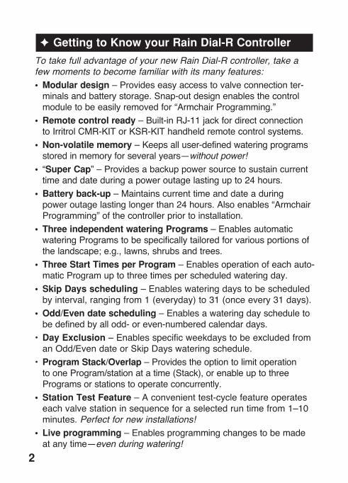
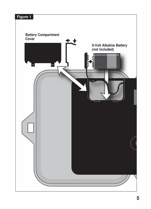
Installinga9Vbattery(user-provided)servestwoimportantfunctions:first,itenablestheRainDial-Rtobefullyprogrammedpriortoinstallation,andsecond,itkeepsthecontrolmodulesynchronizedwithcurrenttimeanddateduringamainpowerinterruptionlastingmorethan24hours .Note: The battery is not capable of operating the sprinkler valves. Main AC power must be applied to the controller to enable operation.Thecontrolmoduleisdesignedtobeeasilyremovedforcompleteprogramminginamoreconvenientsetting,suchasyourfavoritearmchair .Toremovethecontrolmodule,simplyunplugtheribboncableconnectorfromtheprintedcircuitboard,thencarefullyremovethemodulefromit’ssnap-inhinges .TheRainDial-Rfeaturesnon-volatilememory,whichkeepstheprogramminginformationintact,evenifthebatterydiesorisdisconnected .Installing the Battery1 . Openthecontrollerdoor .2 . Pullthecontrolmoduleopenbygraspingitfromtherightedge
(pressthemodulereleasetabontheoutdoormodel) .3 . Pressdownandoutwardontopofthebatterycompartment
covertoremove .SeeFigure 1 .4 . Attachthebatterycliptoa9VAlakalinebattery .5 . Stowthebatteryintothecompartmentandreinstallthecover .6 . Thedisplaywillbeginflashing12:00 AM(pressanybuttontohalt) . Note: To begin setting up a watering Program, refer to
“Basic Programming Procedures” on page 22.CAUTION: To avoid hazards from improper battery type
installation, always replace the battery with the same or equivalent battery type . Always dispose of used batteries properly, as recommended by the battery manufacturer .
4
EARTHGROUND
MV/PUMP
7 8 9 10 11 12
1 2 3 4 5 6
24 VACVC
5
Figure 1
9-Volt Alkaline Battery (not included)
Battery Compartment Cover

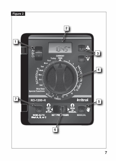
Overview: Control Module Interface
1 - Program Switch • Three-positionslideswitchusedtoselectProgramA,BorC
forsetup,programreviewandmanualoperation .2 - LCD Display
• High-contrastLCDpaneldisplaysallcontrollerprogrammingandoperatinginformation .
3 - Plus and Minus Buttons
• Pushbuttonsusedtoincreaseanddecreasedisplayvaluesduringcontrollersetup,programmingandmanualoperations .Adjustsvaluesincrementally(pressandrelease)orbyrapidscrolling(pressandhold) .
4 - Dial • A25-positionrotaryswitchusedtoselectstations,starttimes,
wateringdaysandspecialfunctionsforsetup,programmingandmanualoperations .
5 - Manual Button • Pushbuttonusedtostartandcontrolmanualoperations
bystation .Alsoservesasa“Next”buttontostepforwardthroughvarioussetup,programmingandmanualoperations .
6 - Function Switch • Athree-positionslideswitchusedtoselectoneofthree
controllerfunctionmodes: Off or Stop -Stopsallcurrentwateringoperations,and
preventsallautomaticandmanualoperations . Set Programs - Enablesautomaticwateringprogramsetup
valuestobeselectedandchanged . Run or Manual - Normalswitchpositionforallautomaticand
manualwateringoperations .7 - Semi-Auto Start Button • Pushbuttonusedtomanuallystartanautomaticwatering
Program .AlsousedtoinitiatetheStationTestRunoperation .
6
7
Figure 2
1
2
3
4
5
6
7
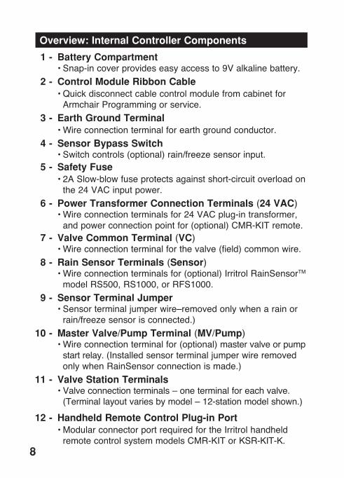
Overview: Internal Controller Components
1 - Battery Compartment •Snap-incoverprovideseasyaccessto9Valkalinebattery . 2 - Control Module Ribbon Cable •Quickdisconnectcablecontrolmodulefromcabinetfor
ArmchairProgrammingorservice . 3 - Earth Ground Terminal •Wireconnectionterminalforearthgroundconductor . 4 - Sensor Bypass Switch •Switchcontrols(optional)rain/freezesensorinput . 5 - Safety Fuse •2ASlow-blowfuseprotectsagainstshort-circuitoverloadon
the24VACinputpower . 6 - Power Transformer Connection Terminals (24 VAC) •Wireconnectionterminalsfor24VACplug-intransformer,
andpowerconnectionpointfor(optional)CMR-KITremote . 7 - Valve Common Terminal (VC) •Wireconnectionterminalforthevalve(field)commonwire . 8 - Rain Sensor Terminals (Sensor) •Wireconnectionterminalsfor(optional)IrritrolRainSensorTM
modelRS500,RS1000,orRFS1000 . 9 - Sensor Terminal Jumper •Sensorterminaljumperwire–removedonlywhenarainor
rain/freezesensorisconnected .) 10 - Master Valve/Pump Terminal (MV/Pump) •Wireconnectionterminalfor(optional)mastervalveorpump
startrelay .(InstalledsensorterminaljumperwireremovedonlywhenRainSensorconnectionismade .)
11 - Valve Station Terminals •Valveconnectionterminals–oneterminalforeachvalve .
(Terminallayoutvariesbymodel–12-stationmodelshown .)
12 - Handheld Remote Control Plug-in Port •ModularconnectorportrequiredfortheIrritrolhandheld
remotecontrolsystemmodelsCMR-KITorKSR-KIT-K .
8

9
1 2 3 4
5
6
7
8
9
1011
Figure 3
12
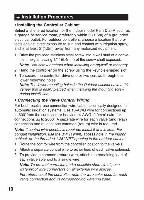
F Installation Procedures
wInstalling the Controller CabinetSelectashelteredlocationfortheindoormodelRainDial-Rsuchasagarageorserviceroom,preferablywithin5'(1 .5m)ofagroundedelectricaloutlet .Foroutdoorcontrollers,choosealocationthatpro-tectsagainstdirectexposuretosunandcontactwithirrigationspray,andisatleast5'(1 .5m)awayfromanymotorizedequipment .1 . Drivetheprovidedstainlesssteelscrewintoawallstudataconve-
nientheight,leaving1/4"(6 .4mm)ofthescrewshaftexposed . Note: Use screw anchors when installing on drywall or masonry. 2 . Hangthecontrolleronthescrewusingthekeyhole-shapedslot .3 . Tosecurethecontroller,driveoneortwoscrewsthroughthe
lowermountingholes . Note: The lower mounting holes in the Outdoor cabinet have a thin
veneer that is easily pierced when installing the mounting screw during installation.
wConnecting the Valve Control WiringForbestresults,useconnectionwirecablespecificallydesignedforautomaticirrigationsystems .Use18-AWGwireforconnectionsupto800'fromthecontroller,orheavier14-AWG(2 .0mm2)wireforconnectionsupto2000' .Aseparatewireforeachvalve(andrelay)connectionandatleastonecommon(return)wireisrequired .Note: If control wire conduit is required, install it at this time. For conduit installation, use the 3/4" (19mm) access hole in the indoor cabinet, or the threaded 1.25" NPT opening in the outdoor cabinet.1 . Routethecontrolwirefromthecontrollerlocationtothevalve(s) .2 . Attachaseparatecontrolwiretoeitherleadofeachvalvesolenoid .3 . Toprovideacommon(return)wire,attachtheremainingleadof
eachvalvesolenoidtoasinglewire . Note: To prevent corrosion and a possible short circuit, use
waterproof wire connectors on all external wire splices. For reference at the controller, note the wire color used for each
valve connection and its corresponding watering zone.
10

4 . Routethecablethroughthelargestopeninginthebaseofthecontrollercabinetorthroughconduitifinstalled .Removethecablejackettoexposeabout8"ofwires .Carefullyremove3/8"ofinsulationfromtheendofeachwiretobeconnected .
5 . Secureeachvalvewiretonumberedterminalinthepreferredoperatingsequenceorder .
6 . Connectthecommonwiretotheterminallabeled“VC .”7 . Ifapplicable,connectonelegofthemastervalveorpumpstart
relaycontrolwiretotheterminallabeled“MV/PUMP”,andtheremaininglegtothevalvecommonwire .
Note: The controller does not supply power to operate a pump. The pump start relay must have a nominal coil voltage of 24 VAC, rated at 0.375A maximum.
EARTHGROUND
MV/Pump Sensor
+ -
7 8 9 10 11 12
1 2 3 4 5 6
24 VACVC
11
Figure 4
Sprinkler Control Valves
Common Wire
Pump Start Relay or Master Valve
1
2
3
MV
24V Relay
Master Valve/Pump Terminal
Valve Common Terminal

Connecting a Rain Sensor (optional) TheRainDial-RisdesignedtoworkinconjunctionwithIrritrolRainSensormodelsRS500,RS1000orRain/FreezesensorRFS1000torestrictwateringwhenmoistureand/ortemperaturelimitsaremet .Note: If connecting an alternate make of rain sensor, ensure it provides normally-closed switch circuit operation.
IMPORTANT: If a rain sensor is not installed, the sensor terminal jumper wire must remain in place, and the sensor switch must remain in the Bypass position . If either of these conditions are not met, automatic and manual operation will be disabled . 1 . Insertthesensorcablethroughthebottomofthecabinet .2 . LoosentheSensorterminalsandremovethejumperwire .3 . RefertotheinstallationinstructionsprovidedwiththeRainSensor
andconnectwiresaccordingly .4 . PlacetheSensorswitchintheActiveposition . Note: When the Rain Sensor is active, all watering
operations will be terminated and SEn (Sensor) will be displayed (in the current time dial position).
EARTHGROUND
MV/Pump Sensor
+ -
7 8 9 10 11 12
1 2 3 4 5 6
24 VACVC
12
Figure 5
Jumper Wire Removed
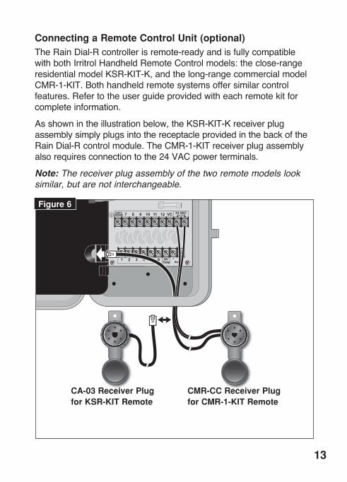
Connecting a Remote Control Unit (optional)TheRainDial-Rcontrollerisremote-readyandisfullycompatiblewithbothIrritrolHandheldRemoteControlmodels:theclose-rangeresidentialmodelKSR-KIT-K,andthelong-rangecommercialmodelCMR-1-KIT .Bothhandheldremotesystemsoffersimilarcontrolfeatures .Refertotheuserguideprovidedwitheachremotekitforcompleteinformation .
Asshownintheillustrationbelow,theKSR-KIT-KreceiverplugassemblysimplyplugsintothereceptacleprovidedinthebackoftheRainDial-Rcontrolmodule .TheCMR-1-KITreceiverplugassemblyalsorequiresconnectiontothe24VACpowerterminals .
Note: The receiver plug assembly of the two remote models look similar, but are not interchangeable.
EARTHGROUND
MV/Pump Sensor
+ -
7 8 9 10 11 12
1 2 3 4 5 6
24 VACVC
13
Figure 6
CMR-CC Receiver Plug for CMR-1-KIT Remote
CA-03 Receiver Plug for KSR-KIT Remote

Connecting an Earth Ground DeviceNote: In order for the electrical surge components built into your Rain Dial-R to function properly, the controller must be connected to an earth ground device, such as a copper-clad ground rod or metal water pipe, using solid copper wire. This connection is especially important when the controller is installed in a lightning-prone area .
1 . Connecta12–16AWG(2mm2–1 .3mm2)solid-copperwiretothegrounddeviceandrouteintothecontrollerthroughanaccessopeninginthebaseofthecabinet .
2 . Securethegroundwiretotheterminallabeled“EarthGround .”
EARTHGROUND
MV/Pump Sensor
+ -
7 8 9 10 11 12
1 2 3 4 5 6
24 VACVC
Metal Water Pipe8' (2 .4 m) Copper-clad Ground Rod (in moist soil)
14
Figure 7
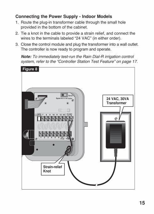
Connecting the Power Supply - Indoor Models 1 . Routetheplug-intransformercablethroughthesmallhole
providedinthebottomofthecabinet .2 . Tieaknotinthecabletoprovideastrainrelief,andconnectthe
wirestotheterminalslabeled“24VAC”(ineitherorder) .3 . Closethecontrolmoduleandplugthetransformerintoawalloutlet .
Thecontrollerisnowreadytoprogramandoperate .
Note: To immediately test-run the Rain Dial-R irrigation control system, refer to the “Controller Station Test Feature” on page 17.
EARTHGROUND
MV/Pump Sensor
+ -
7 8 9 10 11 12
1 2 3 4 5 6
24 VACVC
Figure 8
15
Strain-relief Knot
Strain-relief Knot
24 VAC, 30VA Transformer
Connecting the Power Source - Outdoor Models
WARNING: All electrical components and connection methods must comply with all applicable national and local electrical codes including installation by qualified person-nel . These codes may require a junction box installed on controller’s 1/2" (13mm) NPT nipple and a means in the fixed wiring of disconnecting AC power having a contact separation of at least 0 .120" (3mm) in the line and neutral poles . The connection wire must have insulation rated @ 105° C min .
The controller must be connected to a grounded power source . Do not connect to one phase of a 3-phase power supply used by a pump or other electrical equipment .Prior to connecting controller wiring, verify that power has been turned off at the source by using an AC volt meter .1 . Installa1/2"(13mm)NPTconduitbodytothetransformerthread-
edfitting .Fromtheconduitbody,installelectricalconduitroutingtotheACpowersource(perelectricalcode) .
2 . Pull14AWGthroughtheconduitintotheconduitbody .3 . Usingtwist-onwireconnectors,attachthematingwiresasshown
inFigure 10 .4 . Closeandsecuretheconduitbodycover .5 . Applypowertothecontrollerandcheckcontrolleroperation .If
thecontrollerisnotoperating,disconnectthepoweratthesourceandhaveaqualifiedelectriciancheckforpossibleshortcircuit .
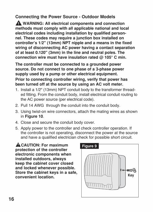
CAUTION: For maximum protection of the controller electronic components when installed outdoors, always keep the cabinet cover closed and locked whenever possible . Store the cabinet keys in a safe, convenient location .
16
Figure 9
Key

Controller Station Test Feature
The controllerStation Test feature enablesyoutoquicklycheckforpropervalvestationoperationafterinitialinstallationorservice .Thetestcycleenablesallvalvestationstooperateinsequenceforatemporaryruntime,adjustablefrom1–10minutes .1 . PlacetheFunction switchintheSet ProgramsorRunposition .2 . TurntheDialtotheSkip Days - Special Functionsposition .3 . PresstheManualbutton(onetime)toselect
theTestRundisplayasshownatright .4 . A2-minutetestruntimeissetbydefault .Toadjusttheruntime
from1–10minutes,pressthe or button .5 . PresstheSemi-Autobuttontostartthewateringcycle(station1
willturnon) .6 . TurntheDialtotheCurrent Timeposition .Thedisplaywill
indicatethecurrentclocktime(initially12:00PM)andstation1 .7 . Tomanuallyadvancethroughthestationoperatingsequence,
presstheManualbutton .
RD-1200
A-+
B-C-
MANUAL
TodaySun
Mon
Wed
Thu
2
3
4
5
6
7
8
9
1011
1232
1
PM
SCHEDULE
START
TIMES
VALVERUNTIMES
17
Figure 10
1 2 3 4 5 6 7 8 9 10 11 12
Equipment Ground to Green or Green/Yellow
Hot or L2 to Black or Brown
Neutral or L1 to White or Blue
Conduit Body
Electrical Conduit
F Getting the Most from Your Rain Dial-R Controller
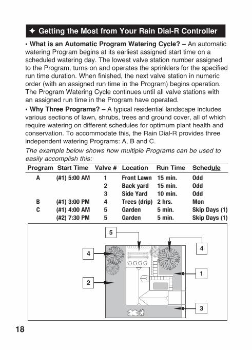
• What is an Automatic Program Watering Cycle? –AnautomaticwateringProgrambeginsatitsearliestassignedstarttimeonascheduledwateringday .ThelowestvalvestationnumberassignedtotheProgram,turnsonandoperatesthesprinklersforthespecifiedruntimeduration .Whenfinished,thenextvalvestationinnumericorder(withanassignedruntimeintheProgram)beginsoperation .TheProgramWateringCyclecontinuesuntilallvalvestationswithanassignedruntimeintheProgramhaveoperated .• Why Three Programs? – Atypicalresidentiallandscapeincludesvarioussectionsoflawn,shrubs,treesandgroundcover,allofwhichrequirewateringondifferentschedulesforoptimumplanthealthandconservation .Toaccommodatethis,theRainDial-RprovidesthreeindependentwateringPrograms:A,BandC .The example below shows how multiple Programs can be used to easily accomplish this: Program Start Time Valve # Location Run Time Schedule
A (#1)5:00AM 1 FrontLawn 15min. Odd 2 Backyard 15min. Odd 3 SideYard 10min. Odd B (#1)3:00PM 4 Trees(drip) 2hrs. Mon C (#1)4:00AM 5 Garden 5min. SkipDays(1) (#2)7:30PM 5 Garden 5min. SkipDays(1)
18
• Avoid unexpected start times –Itispossibletosetasecondstarttimethatbeginsbeforethewateringcyclefromthefirststarttimehasfinished .Whenthishappens,thestartofthesecondcycleisdelayeduntilthefirstiscomplete;sothestarttimemaynotoccurwhenyouexpectit .Inaddition,increasingruntimewiththewaterbudgetfeaturemaycauseanoverlapthatdelaysthenextscheduledstarttime .
• Avoid watering on a non-watering day – AwateringcyclethatcontinuesbeyondMidnightwillruntocompletionregardlessifthenextdayisscheduledforwatering .• Avoid excessive watering –Bydefault,ProgramsA,BandCcanbescheduledtorunconcurrently(overlap) .ThisfeaturecanberestrictedbyselectingtheProgramStackingoption(seepage28) .Starttimesenteredforanyprogramwillbeginautomaticallywhenthattimeoccurs .Usingmultipleprogramsenablesvalvestationstowaterondifferentschedulesortoprovideadditionalwateringifoneprogramisnotenough .Ifyouneedextrawater,usemorethanonestarttimeand/orusetheWaterBudgetfeaturetoincreasethevalvestationruntime .• Avoid Creating a low water pressure condition – Starttimesassignedtodifferentprogramsareindependent .Ifyousetidenticaloroverlappingstarttimes,morethanonevalvestationcanrunatthesametime .Thetotalflowmayexceedtheavailablewatersupply .Toavoidthissituation,allowmoretimebetweenstarttimestoreducethenumberofvalvesrunningatonetime,andmakesurethatmultipleProgramsdonothavethesamestarttimes .• Establishing new lawns–Havingshort,multiplewateringcycleseachdayisespeciallyusefulwhenestablishinganewlawn .
• Help with electrical problems –TheRainDial-Rwilldisplaythestationnumberandtheword“FUS”ifashort-circuitonavalvestationisdetected .Thedetectedstationwillbebypassed,allowingtheremainingstationstorunintheProgramwateringcycle .
19
F What the Display Indicates
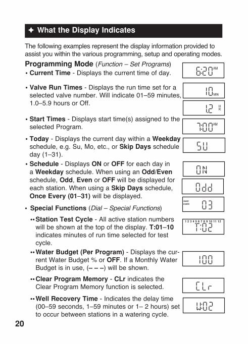
Thefollowingexamplesrepresentthedisplayinformationprovidedtoassistyouwithinthevariousprogramming,setupandoperatingmodes .Programming Mode (Function – Set Programs)• Current Time-Displaysthecurrenttimeofday .
• Valve Run Times-Displaystheruntimesetforaselectedvalvenumber .Willindicate01–59minutes,1 .0–5 .9hoursorOff .
• Start Times-Displaysstarttime(s)assignedtotheselectedProgram .
• Today-DisplaysthecurrentdaywithinaWeekdayschedule,e .g .Su,Mo,etc .,orSkip Daysscheduleday(1–31) .
• Schedule-DisplaysONorOFF foreachdayinaWeekdayschedule .WhenusinganOdd/Evenschedule,Odd,EvenorOFFwillbedisplayedforeachstation .WhenusingaSkip Daysschedule,Once Every (01–31) willbedisplayed .
• Special Functions (Dial – Special Functions) •• Station Test Cycle-Allactivestationnumbers
willbeshownatthetopofthedisplay .T:01–10indicatesminutesofruntimeselectedfortestcycle .
•• Water Budget (Per Program)-Displaysthecur-rentWaterBudget%orOFF .IfaMonthlyWaterBudgetisinuse,(– – –)willbeshown .
•• Clear Program Memory-CLrindicatestheClearProgramMemoryfunctionisselected .
•• Well Recovery Time-Indicatesthedelaytime(00–59seconds,1–59minutesor1–2hours)settooccurbetweenstationsinawateringcycle .
20
1 2 3 4 5 6 7 8 9 10 11 12
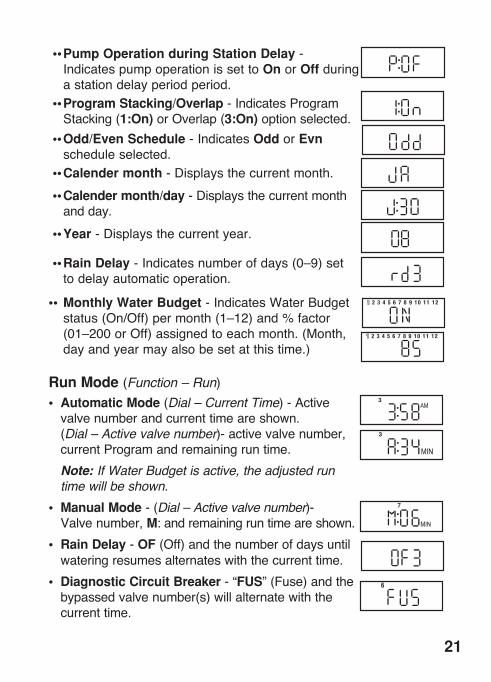
•• Pump Operation during Station Delay -IndicatespumpoperationissettoOnorOffduringastationdelayperiodperiod .
•• Program Stacking/Overlap-IndicatesProgramStacking(1:On)orOverlap(3:On) optionselected .
•• Odd/Even Schedule -IndicatesOddorEvnscheduleselected .
•• Calender month -Displaysthecurrentmonth . •• Calender month/day -Displaysthecurrentmonth
andday . •• Year -Displaysthecurrentyear .
•• Rain Delay-Indicatesnumberofdays(0–9)settodelayautomaticoperation .
•• Monthly Water Budget -IndicatesWaterBudgetstatus(On/Off)permonth(1–12)and%factor(01–200orOff)assignedtoeachmonth .(Month,dayandyearmayalsobesetatthistime .)
Run Mode (Function – Run)• Automatic Mode (Dial – Current Time)-Active
valvenumberandcurrenttimeareshown .(Dial – Active valve number)-activevalvenumber,currentProgramandremainingruntime .
Note: If Water Budget is active, the adjusted run time will be shown.
• Manual Mode-(Dial – Active valve number)-Valvenumber,M:andremainingruntimeareshown .
• Rain Delay-OF(Off)andthenumberofdaysuntilwateringresumesalternateswiththecurrenttime .
• Diagnostic Circuit Breaker-“FUS”(Fuse)andthebypassedvalvenumber(s)willalternatewiththecurrenttime .
21
F Basic Programming Procedures
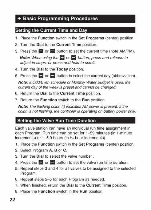
Setting the Current Time and Day
1 . PlacetheFunction switchintheSet Programs(center)position .2 . TurntheDialtotheCurrent Timeposition .3 . Pressthe or buttontosetthecurrenttime(noteAM/PM) . Note: When using the or button, press and release to
adjust in steps, or press and hold to scroll. 4 . TurntheDialtotheTodayposition .5 . Pressthe or buttontoselectthecurrentday(abbreviation) . Note: If Odd/Even schedule or Monthly Water Budget is used, the
current day of the week is preset and cannot be changed.6 . ReturntheDialtotheCurrent Timeposition .7 . ReturntheFunction switchtotheRunposition . Note: The flashing colon (:) indicates AC power is present. If the
colon is not flashing, the controller is operating on battery power only.
Setting the Valve Run Time Duration
EachvalvestationcanhaveanindividualruntimeassignmentineachProgram .Runtimecanbesetfor1–59minutes(in1-minuteincrements)or1–5 .9hours(in1/10-hourincrements) .1 . PlacetheFunction switchintheSet Programs(center)position .2 . SelectProgramA,BorC .3 . TurntheDialtoselectthevalve number .4 . Pressthe or buttontosetthevalveruntimeduration .5 . Repeatsteps3and4forallvalvestobeassignedtotheselected
Program .6 . Repeatsteps2–5foreachProgramasneeded .7 . Whenfinished,returntheDialtotheCurrent Timeposition .8 . PlacetheFunction switchintheRunposition .
22
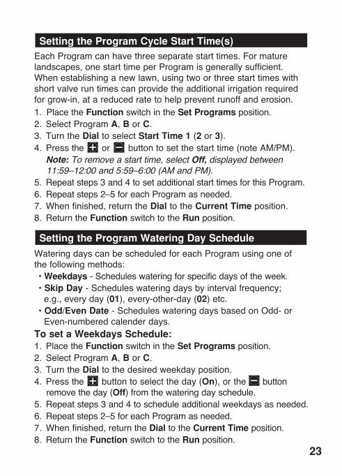
Setting the Program Cycle Start Time(s)EachProgramcanhavethreeseparatestarttimes .Formaturelandscapes,onestarttimeperProgramisgenerallysufficient .Whenestablishinganewlawn,usingtwoorthreestarttimeswithshortvalveruntimescanprovidetheadditionalirrigationrequiredforgrow-in,atareducedratetohelppreventrunoffanderosion .1 . PlacetheFunction switchintheSet Programsposition .2 . SelectProgramA,BorC .3 . TurntheDialtoselectStart Time 1 (2 or 3) .4 . Pressthe or buttontosetthestarttime(noteAM/PM) . Note: To remove a start time, select Off, displayed between
11:59–12:00 and 5:59–6:00 (AM and PM).5 . Repeatsteps3and4tosetadditionalstarttimesforthisProgram .6 . Repeatsteps2–5foreachProgramasneeded .7 . Whenfinished,returntheDialtotheCurrent Timeposition .8 . ReturntheFunction switchtotheRunposition .
Setting the Program Watering Day Schedule
WateringdayscanbescheduledforeachProgramusingoneofthefollowingmethods: •Weekdays-Scheduleswateringforspecificdaysoftheweek . •Skip Day-Scheduleswateringdaysbyintervalfrequency;
e .g .,everyday(01),every-other-day(02)etc . •Odd/Even Date-ScheduleswateringdaysbasedonOdd-or
Even-numberedcalenderdays .To set a Weekdays Schedule:1 . PlacetheFunction switchintheSet Programsposition .2 . SelectProgramA,BorC .3 . TurntheDialtothedesiredweekdayposition .4 . Pressthe buttontoselecttheday(On),orthe button
removetheday(Off)fromthewateringdayschedule .5 . Repeatsteps3and4toscheduleadditionalweekdaysasneeded .6 . Repeatsteps2–5foreachProgramasneeded .7 . Whenfinished,returntheDialtotheCurrent Timeposition .8 . ReturntheFunction switchtotheRunposition .
23
Note: Each Program can have a Skip Days or an Odd/Even Date watering schedule, but not both. One schedule must be turned off to enable the alternate schedule to be selected.To Set a Skip Day Schedule:1 . PlacetheFunction switchintheSet Programsposition .2 . SelectProgramA,BorC .3 . TurntheDialtotheSkip Days/Special Functions position .4 . Pressthe / buttonstoselecttheSkip Day interval
(01–31) days .
Note:To turn Off a Skip Day schedule, press the or button to display OFF.
5 . TurntheDialtotheToday position .6 . Pressthe / buttonstoselectthecurrentdaywithinthe
SkipDayintervalschedule . Note: For example, if you have selected a 3-day schedule, and
prefer to have watering start today, select 03. To water tomor-row, select 02. To watering in three days, select 01.
7 . Repeatsteps2–6foreachProgramasneeded .8 . Whenfinished,returntheDialtotheCurrent Timeposition .9 . ReturntheFunction switchtotheRunposition .
To Set an Odd/Even Date Schedule:1 . PlacetheFunction switchintheSet Programsposition .2 . SelectProgramA,BorC .3 . TurntheDialtotheSkip Days - Special Functions position .4 . PresstheManualbutton(seventimes)todisplaydashes(– – –) .5 . Pressthe buttontoselectOdd,orthe buttontoselect
Even (EVn) . Note:To turn Off an Odd/Even Date schedule, press the
or button to display dashes (– – –).6 . PresstheManualbutton(onetime)toselectthecalendar
Month –January(JA)willbedisplayed .
24

7 . Pressthe / buttonstoadjustthemonthsetting . JA-January,Fe-February,MR-March,AP-April,My-May,
JN-June,JL-July,AU-August,SE-September,OC-October,nO-November,andDE-December .
8 . PresstheManualbutton(onetime)toselecttheDaysetting .9 . Pressthe / buttonstoselectthecurrentcalendarday .
Example: September 17th would be displayed as S:17.10 .PresstheManualbutton(onetime)toselecttheYearsetting .11 .Pressthe / buttonstoselecttheyear(09 =2009) .13 .Whenfinished,returntheDialtotheCurrent Timeposition .12 .Repeatsteps2–10foreachProgramasneeded .14 .ReturntheFunction switchtotheRunposition .Note: When an Odd/Even schedule is used, confirm that the current day of the week is correctly set by turning the Dial to the Today position. If the day of the week is incorrect, adjust the month, day and year settings to properly synchronize the controller. Also note that when using an Odd/Even schedule, watering never occurs on the 31st of any month or February 29th of a leap year.Day Exclusion FeatureWhenusingaSkipDaysandOdd/Evendatewateringschedule,wateringwillnotoccuronthesamedaysfromweektoweek .Torestrictwateringonspecificweekdays;e .g .,forscheduledmowingormaintenance,usetheDayExclusionfeatureasfollows:1 .PlacetheFunction switchintheSet Programsposition .2 . SelectProgramA,BorC .3 . TurntheDialtotheDay tobeexcluded .4 . Pressthe buttondisplayOFF .5 . Repeatsteps3and4toexcludeadditionaldays .6 . ReturntheDialtotheCurrent Time position .7 .ReturntheFunction switchtotheRunposition .
v This completes the basic programming requirements for automatic operation . To utilize the various Rain Dial-R Special Functions, continue on pages 26–29 .
25

F Special Functions
Rain Delay
TheRain Delay feature enablesautomaticwateringoperationtobesuspendedforaperiodof1to9days;thenresumewateringautomaticallyasscheduled .1 . PlacetheFunction switchintheSet Programs position .2 . TurntheDialtotheSkip Days - Special Functionsposition .3 . PresstheManualbutton(repeatedly)todisplayrd0
(RainDelay=0days) .4 . Pressthe / buttonstoselectaRainDelayperiodof1to9
days .5 . ReturntheDialtotheCurrent Timeposition .6 . ReturntheFunction switchtotheRun position . Note: When the Rain Delay function is active, the display will
alternately indicate the current time of day and the number of days remaining until automatic operation resumes. To cancel Rain Delay at any time, decrease Rain Delay setting to 0 days.
Water Budget
TheWater Budgetfeatureenablestheruntimeofallstations,assignedtoaspecificProgram,tobesimultaneouslyadjustedupordownbypercentage .Fromthebaselineof100%,runtimescanbereducedto0%(Off)orincreasedupto200% .Toreducethepossibilityofover-wateringwhenselectingaWaterBudgetvalueabove100%,theadjustedruntimeisautomaticallycutinhalf,andthewateringcycleruntwice .Forexample,adjustingto200% would first increase a 20-minute station run time to 40 min-utes,thensplitthetimeinhalfandruntwowateringcyclesback-to-backwith20minutesduringeachcycle .Allzoneruntimesareretainedinthetimermemoryandreturnedtotheirsetvaluewhentheseasonadjustisresetto100% .Theonlytimeastationruntimewillappearchangedisduringoperation .
26
Foradditionalcontrol,aWaterBudgetfactorcanbeassigneduni-versallytoaProgram,orappliedtoaProgrambyspecificmonthsoftheyear–whenWaterBudgetingbyseasonaldemandispreferred .Note: Each Program is limited to one Water Budget method at a time. Applying a Water Budget by monthly demand will override a basic Water Budget adjustment value. Conversely, to apply a basic Water Budget, all months must be set at 100%.To Apply a Basic Water Budget:
1 . TurntheDialtotheSkip Days - Special Functionsposition .2 . SelectProgramA,BorC .3 . PlacetheFunction switchintheSet Programs position .4 . PresstheManualbutton(twice)todisplay100 (%) .5 . Pressthe or buttontoadjustthe%factor(10%increments) . Note: Decreasing the Water Budget value beyond 10% to “OFF”
prevents the Program from running automatically. 6 . ReturntheDialtotheCurrent Time position .7 . ReturntheFunction switchtotheRunposition .
To Apply a Monthly Water Budget:
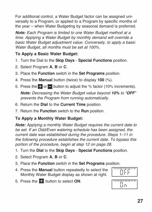
Note: Applying a monthly Water Budget requires the current date to be set. If an Odd/Even watering schedule has been assigned, the current date was established during the procedure. Steps 1–11 in the following procedure establishes the current date. To bypass this portion of the procedure, begin at step 12 on page 28.1 . TurntheDialtotheSkip Days - Special Functionsposition .2 . SelectProgramA,BorC .3 . PlacetheFunction switchintheSet Programs position .4 . PresstheManual buttonrepeatedlytoselect the
MonthlyWaterBudgetdisplayasshownatright .5 . Pressthe buttontoselectON .
27
1 2 3 4 5 6 7 8 9 10 11 12
1 2 3 4 5 6 7 8 9 10 11 12

6 . PresstheManualbuttononetimetoselectthecalendarMonthsetting .January(JA)willbedisplayed .
7 . Pressthe or buttontoselectthecurrentmonthabbreviation:JA-January(1),Fe-February(2),MR-March(3),AP-April(4),My-May(5),JN-June(6),JL-July(7),AU-August(8),SE-September(9),OC-October(10),nO-November(11)andDE-December(12) .
8 . Withthemonthselected,presstheManual buttononetimetoselecttheDaysetting .
9 . Usethe / buttonstoselectthecurrentcalendarday .For example, April 4 would be displayed as A:04.
10 .PresstheManual buttononetimetoselecttheYearsetting .
11 .Pressthe / buttonstoselectthecurrentyear(09=2009) .12 .PresstheManual button(asneeded)toselect
theMonthlyWaterBudgetdisplay .1(January)isselectedwithitscurrentWaterBudgetvalue(100%bydefault) .
13 .Tochangethemonthselection,presstheManualbutton .
14 .Pressthe / buttonstoadjustthe%factorin1%incrementsdownorup(Offor10%–200%) .
15 .Repeatsteps13and14tosetadditionalmonths .15 .Whenfinished,returntheDialtotheCurrent Timeposition .16 .ReturntheFunction switchtotheRunposition .
Stack/Overlap
TheStack/Overlap optiondetermineshowthecontrollerwillmanageconcurrentlyscheduledprogramsormanuallystartedvalvestations .Bydefault,theOverlapoptionisselected,enablingsimultaneousoperationofuptothreeProgramsormanualvalvestations .SelectingtheStackoptionlimitsoperationtoeitheroneautomaticProgramormanualvalvestation .
28
Important: •The Stack option prevents a scheduled Program or manually
operated valve station from operating until any current opera-tion has been completed or canceled. At midnight, any remaining scheduled Programs stacked in queue will be canceled.
• Selecting the Overlap option can cause the electrical and/or hydraulic capacity of your irrigation system to be exceeded. Always plan your watering schedule carefully!
1 . TurntheDialtotheSkip Days - Special Functionsposition .2 . PlacetheFunction switchintheSet Programs position .3 . PresstheManualbuttonrepeatedlytodisplay3:On (three
programsorstationscanrunconcurrently) .4 . ToselecttheStackoption,pressthe / buttontochoose1:On .5 . ReturntheDialtotheCurrent Time position .6 . ReturntheFunction switchtotheRunposition .
Station Delay
Irrigationsystemsthatutilizeawell-watersourceorhaveslow-closingvalves,mayrequireadelayperiodtooccurbetweencon-secutivestationsduringawateringcycle .TheStationDelayfeatureenablesadelayperiodtobesetfrom1secondto2hours .1 . PlacetheFunction switchintheSet Programsposition .2 . PlacetheProgramswitchtoselectA,BorC .3 . TurntheDialtotheSkip Days - Special Functions position .4 . PresstheManualbuttonrepeatedlytodisplayW:00 (nodelay) .5 . Pressthe / buttonstosetthedelaytime:00–59seconds,
01–59minutes(MIN)or1 .0–2 .0hours(HR .) . Note: Hold the button down to scroll. The display will continuously
scroll from seconds to minutes to hours (:00 = no delay time).6 . ReturntheDialtotheCurrent Time position .7 . ReturntheFunction switchintheRunposition .
29
Pump Control During Station Delay
ThePumpControlfeatureisgenerallyusedinconjunctionwiththeStationDelayfeature,enablingthepump/mastervalvetobeturnedonoroffbetweenconsecutivestationsduringawateringcycle .Forexample,asystemwithslow-closingvalvesmayrequireanauxiliarypumptoremainonthroughoutthewateringcycletoassistvalveclosure .Alternately,asystemutilizingawell-watersupplysourcemayrequiretheauxiliarypumptobeoffwhenanextendeddelayperiodbetweenstationsisrequiredforadequatewell-recoverytime .1 . PlacetheFunction switchintheSet Programsposition .2 . PlacetheProgramswitchtoselectA,BorC .3 . TurntheDialtotheSkip Days - Special Functions position .4 . PresstheManualbutton(repeatedly)todisplayP:OF (PumpOff) .5 . Pressthe / buttontotogglebetweenP:OFandP:On 6 . ReturntheDialtotheCurrent Time position .7 . ReturntheFunction switchintheRunposition .
Pump Control Option
Bydefault,thepumpcontrolcircuitisactivatedsimultaneouslywithanyautomaticormanualvalvestationoperation .Whenpumpoper-ationisnotrequiredforspecificvalvestations;e .g .,dripirrigation,thepumpcontrolcircuitcanbeeasilydisabledasneeded .Note: The Pump control option applies to the selected valve station regardless of its Program assignment. 1 . PlacetheFunction switchintheSet Programsposition .2 . TurntheDialtoselecttheappropriatevalvestationnumber .3 . PresstheManualbutton:P:On(PumpOn)willbedisplayed .4 . Todisablethepumpcontrolcircuitfromthevalvestation,
pressthe buttontodisplayP:OF (PumpOff) .5 . Repeatsteps2–4foradditionalvalvestationsasrequired .6 . ReturntheDialtotheCurrent Time position .7 . ReturntheFunction switchtotheRunposition .
30
F Diagnostic Circuit Breaker
Theprompt“FUS”andthemalfunctioningvalvestationnumberwillbealternatelydisplayedwiththecurrenttime .Thevalvestationwillbebypassedduringthewateringcycle,enablingallremainingvalvestationstorunasscheduled .WiththeDialsetintheCurrent Time position,pressanybuttontoclearthe“FUS”display .
Important:Determine the cause of the malfunction and take corrective action as necessary . Clearing the display will not resolve the problem .
F Fuse Replacement
Caution: The 2 .0A safety fuse protects the transformer from damage due an excessive current load (short circuit) condition . Locate and eliminate the cause of the problem before replacing the fuse . For continued protection against risk of fire, replace only with the same fuse type and rating .
1 . Disconnectpowertothecontroller .2 . Carefullyremovethesafetyfusefromtheterminalboard(see
page9forfuselocation) .3 . Installanew2 .0Aslow-blowfuse,ensuringthatitisproperly
seatedintheretainingclip .4 . Reconnectpowertothecontroller .
31
F Manual Operations
Semi-automatic Program Operation
Semi-AutomaticProgramoperationenablesanautomaticProgramwateringcycletobestartedmanuallyatanytime .Oncerunning,themanualadvancefeatureenablesyoutostepthroughthepro-grammedstationsequence .1 . PlacetheFunction switchintheRunposition .2 . TurntheDialtotheCurrent Time position .3 . PlacetheProgramswitchtoselectA,BorC .4 . PresstheSemi-Autobuttontostartthewateringcycle . Note: Once started, the station sequence can be manually
advanced by placing the Dial to Current Time and pressing the Manual button.
Note: The Manual Advance feature applies to all Automatic, Semi-automatic and Station Test watering operations for the selected Program.
Note: To terminate watering operations, place the Function switch momentarily in the OFF or Stop position.
32
Manual Station Operation
Manualstation operationprovidesmanualcontrolattheindividualstationlevelandprovidesthefollowingfourcontroloptions:• Station(s)canbeoperatedforaone-timerundurationwithout
alteringthestation’ssetruntimeinanautomaticProgram .• Operationcanbelimitedtoonlyonestationrunningmanually
orsettoallowthreestationstorunatthesametime . Note: Refer to “Stack/Overlap Option” on page 26 for additional
information regarding manual operations.• WorkswiththeManualAdvancefeaturetomoveupthroughthe
stationsequence .1 . PlacetheFunction switchintheRunposition .2 . TurntheDialtotheStation Number tobemanuallyoperated .3 . Usethe / buttonstosetamanualoperationruntime
rangingfrom1minuteto5 .9hours .4 . PresstheManual buttontostarttheoperation .5 . Ifthisistheonlystationtoberunmanually,skipstep6and
continueatstep7below .6 . Toaddadditionalstationstothemanualrunoperation,repeat
steps2through4asneeded,thencontinueatstep7 . Note: Depending upon the Stack/Overlap setting, additional
stations selected (beyond the one or three option setting) will register as OFF when entered with the Manual button. However, they will be placed (stacked) in the manual sequence to run.
7 . TurntheDialtotheCurrent Timeposition . Note: Once started, the station sequence can be manually
advanced by pressing the Manual button. Note: To terminate manual watering operations, place the
Function switch momentarily in the OFF or Stop position.
33
34
F Clear Program Memory
TheClear ProgramMemoryfeatureenablesyoutosafelycleartheautomaticwateringprogramsettingsdefinedforaspecificProgramwithoutaffectinganyremainingPrograminformation .ThememoryerasefunctionappliesonlytothespecifiedProgram,leavingtheremainingProgramsintact .
Important:The “Clear Program” function completely erases all user-defined programming information from the selected Program including: start times, run times, and watering day schedule .
Note: To return the Program back to factory default settings, refer to “Reset Factory Default Programming” on page 35.
1 . PlacetheFunction switchintheSet Programsposition .2 . PlacetheProgramswitchtoselectA,BorC .3 . TurntheDialtotheSkip Days - Special Functions position .4 . PresstheManualbuttonrepeatedlytodisplayCLr (Clear) .5 . Pressthe buttononetime .Thedisplaywillshowtheprompt:
CL?(Clear?) .6 . Tocompletetheprocess,pressthe buttonagaintodisplay
theprompt“End” .7 . ReturntheDialtotheCurrent Time position .8 . ReturntheFunction switchtotheRunposition .

35
F Restore Rain Dial-R to Factory Default Settings
TheRainDial-Rfactorydefaultsettingsforautomaticprogramoperationareasfollows:CurrentTime:12:00AM .CurrentDay:Sunday .CurrentDate:January1,2008 .ProgramA:Weekdaywateringschedulewithalldaysactive . Onestarttimeat7:00AM . 10-minuteruntimeonallvalvestations .ProgramBandC:Nowateringdays,stationruntimesorstarttimes .SkipDaysandOdd/Evendayschedule:OFF-allPrograms .ExcludeddaysinSkipDaysorOdd/Evenschedule:None .MV/Pumpoperation:ON-allstations .WellRecoveryperiod:00(OFF)-allPrograms .MV/PumpoperationduringWellRecovery:OFF-allPrograms .WaterBudget:100%-allProgramsandmonths .RainDelay:0days .Stack/Overlap:Overlap-3Programsor3manualstations .To restore factory default settings:
1 . PlacetheFunction switchintheSet Programposition .2 . PlacetheProgramswitchtoselectProgramB .4 . Openthebatterycompartmentanddisconnectthebattery .3 . LeavingtheACpowerconnected,carefullyunplugthecontrol
moduleribboncablefromtheterminalBoardsocket .5 . PressandholdtheManualbutton .6 . PlugintheribboncableandreleasetheManualbutton . Note: With the dial in the Current Time position, the display
should now show 12:00 AM. If it does not, repeat the procedure as necessary.
7 . Connectthebattery .8 . Reprogramthecontroller .
36
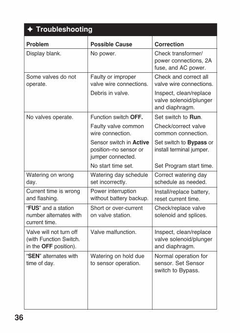
Problem
Displayblank .
Somevalvesdonotoperate .
Novalvesoperate .
Wateringonwrongday .Currenttimeiswrongandflashing .“FUS”andastationnumberalternateswithcurrenttime .Valvewillnotturnoff(withFunctionSwitch .intheOFFposition) .“SEN”alternateswithtimeofday .
Possible Cause
Nopower .
Faultyorimpropervalvewireconnections .Debrisinvalve .
FunctionswitchOFF .Faultyvalvecommonwireconnection .Sensorswitchin Activeposition–nosensororjumperconnected .Nostarttimeset .Wateringdayschedulesetincorrectly .Powerinterruptionwithoutbatterybackup .Shortorover-currentonvalvestation .
Valvemalfunction .
Wateringonholdduetosensoroperation .
Correction
Checktransformer/powerconnections,2Afuse,andACpower .Checkandcorrectallvalvewireconnections .Inspect,clean/replacevalvesolenoid/plungeranddiaphragm .SetswitchtoRun .Check/correctvalvecommonconnection .SetswitchtoBypassorinstallterminaljumper .
SetProgramstarttime .Correctwateringdayscheduleasneeded .Install/replacebattery,resetcurrenttime .Check/replacevalvesolenoidandsplices .
Inspect,clean/replacevalvesolenoid/plungeranddiaphragm .Normaloperationforsensor .SetSensorswitchtoBypass .
F Troubleshooting

37
F Contact Information
Thetroubleshootingsolutionsareprovidedtohelpresolveproblemsthatmayariseduringsetupand/oroperationoftheRainDial-Rcontroller .Iftheproblemisnotlistedorcannotberesolvedwiththeprovidedsolutions,contactanauthorizedIrritrolproductexpertforassistanceviaphoneoremail .U .S ./Canada: Phone:1-800-634-8873(7:30am–4pm,M–F,PT) E-mail:irrigationsupport@irritrol .comEurope: Phone:+39-076540191 E-mail:intlirrigationsupport@irritrol .comAustralia: Phone:+61883003633 E-mail:intlirrigationsupport@irritrol .com

F Specifications
Outdoor Models: • Input:120VAC60Hz,30VA(Domestic), 230/240VAC,50Hz,30VA(International)Indoor Models: • Input(fromplug-intransformer):24VAC,60Hz,30VA (domestic),24VAC,50Hz,30VA(InternationalandAustralian)All Models: • StationOutput:24VACat0 .5A,1 .0A(maximumtotal) • MasterValve/PumpStartRelayOutput:24VACat0 .375A • 2 .0ASlow-blowFuse • BatteryBack-up(time,dayanddate) • Operating temperature range: 32˚F to 140˚F (0˚C to 60˚C)
Caution: The Rain Dial is designed to operate 24 VAC valve solenoids rated at 0 .25A (6 VA) . Total current load during operation must not exceed 1 .0A . A maximum of two solenoids per station terminal may be used if the total station load does not exceed 0 .5A . No more than three solenoids (plus MV/Pump circuit) should operate concurrently . In irrigation systems where multiple controllers are used, each controller must utilize a sepa-rate valve common circuit .FCC Rules - Domestic: ThisequipmenthasbeentestedandfoundtocomplywiththelimitsforaClassBdig-italdevice,pursuanttoSubpartJofPart15oftheFCCRules .Theselimitsaredesignedtoprovidereasonableprotectionagainstharmfulinterferenceinaresidentialinstallation .Thisequipmentgenerates,usesandcanradiateradiofrequencyenergyand,ifnotinstalledandusedinaccordancewiththeinstructions,maycauseharmfulinterferencetoradiocommunications .However,thereisnoguaranteethatinterferencewillnotoccurinaparticularinstallation .Ifthisequipmentdoesharmfulinterferencetoradioortelevisionreception,whichcanbedeterminedbyturningtheequipmentoffandon,theuserisencouragedtotrytocorrecttheinterfer-encebyoneormoreofthefollowingmeasures:1 . Reorientorrelocatethereceivingantenna .2 . Increasetheseparationbetweentheequipmentandreceiver .3 . Connecttheequipmentintoanoutletonacircuitdifferentfromthattowhichthereceiverisconnected .4 . Consultthedealeroranexperiencedradio/TVtechnicianforhelp .TheusermayfindthefollowingbookletpreparedbytheFederalCommunicationsCommissionhelpful:“HowToIdentifyandResolveRadio-TVInterferenceProblems .”ThisbookletisavailablefromtheU .S .GovernmentPrintingOffice,Washington,DC20402,stock#004-000-00345-4 .International:ThisisaCISPR22ClassBproduct .
©2009Irritrolwww .irritrol .com FormNumber373-0538Rev .A