Embed Size (px)
Citation preview

User’s ManualAll-in-one Collaboration Solution
NEC 65” InfinityBoard 2.0 / 2.1
NEC 75” InfinityBoard 2.0 / 2.1
NEC 86” InfinityBoard 2.0 / 2.1
MONITOR MODEL: V654Q IGB, V754Q IGB, V864Q IGB
Please find your model name on the label on rear side of the monitor.

Index
Addendum to User’s Manuals of MultiSync V654Q, V754Q, V864Q……..……………… Page 03
Registration Information……………………………………………………………………….. Page 04
Important Information………………………………………………………………………….. Page 06
Safety Precautions, Maintenance & Recommended Use…………………………………. Page 07
Shipping Content………………………………………………………………………………..Page 08
Unpacking………………………………………………………………………………………. Page 09
General Installation…………………………………………………………………………….. Page 10
InfinityBoard Assembly Instruction…………………………………………………………….Page 11
Setup the OPS Slot-in PC…………………………………………………………………….. Page 17
Troubleshooting………………………………………………………………………………….Page 19
Specifications – 65” InfinityBoard 2.0 / 2.1……………………………………………………Page 21
Specifications – 75” InfinityBoard 2.0 / 2.1……………………………………………………Page 25
Specifications – 86” InfinityBoard 2.0 / 2.1……………………………………………………Page 30
Manufacturer’s Recycling and Energy Information…………………………………………. Page 33

Addendum to User’s Manuals of MultiSync V654Q, V754Q, V864Q
This user’s manual is an addendum to the standard user’s manual of the base model monitors V654Q, V754Q and V864Q.
All specifications listed here supersede those in the standard version of the manual included with this monitor.
NOTE: Following feature sets are not supported by the InfinityBoard models:
- Table Top Stand Option: Other than the standard monitor, the NEC InfinityBoard does not allow for table top installations, as the table top brackets has been removed
- Room Light Sensing Sensor: Other than the standard monitor, the NEC InfinityBoard does not allow the monitor to make automatic adjustments to the backlight setting.
- Intelligent Wireless Data Sensor: Other than the standard monitor, the NEC InfinityBoard does not include a sensor for wireless communication to the monitor for information and settings.
- NEC ornament logo: Other than the standard monitor, the NEC InfinityBoard does not have an ornament logo. Therefore changing the position of the NEC logo is not possible.

Registration Information
Cable Information
CAUTION: Use the provided specified cables with this product so as not to interfere with radio and
television reception. For USB please use a shielded signal cable with ferrite core. For HDMI,
DisplayPort and D-Sub 9-pin, please use a shielded signal cable. For Audio, please use a signal cable
with ferrite core. Use of other cables and adapters may cause interference with radio and television
reception.
FCC Information
WARNING: The Federal Communications Commission does not allow any modifications or changes to the unit EXCEPT those specified by NEC Display Solutions of America, Inc. in this manual. Failure to comply with this government regulation could void your right to operate this equipment.
This equipment has been tested and found to comply with the limits for a Class B digital device, pursuant to part 15 of the FCC Rules. These limits are designed to provide reasonable protection against harmful interference in a residential installation. This equipment generates, uses and can radiate radio frequency energy, and, if not installed and used in accordance with the instructions, may cause harmful interference to radio communications. However, there is no guarantee that interference will not occur in a particular installation. If this equipment does cause harmful interference to radio or television reception, which can be determined by turning the equipment off and on, the user is encouraged to try to correct the interference by one or more of the following measures:
• Reorient or relocate the receiving antenna.
• Increase the separation between the equipment and receiver.
• Connect the equipment into an outlet on a circuit different from that to which the receiver is connected.
• Consult the dealer or an experienced radio/TV technician for help.
If necessary, the user should contact the dealer or an experienced radio/television technician for additional suggestions. The user may find the following booklet, prepared by the Federal Communications Commission, helpful: “How to Identify and Resolve Radio-TV Interference Problems.” This booklet is available from the U.S. Government Printing Office, Washington, D.C., 20402, Stock No. 004-000-00345-4.
DECLARATION OF CONFORMITY
This device complies with Part 15 of FCC Rules. Operation is subject to the following two conditions. (1) This device may not cause harmful interference, and (2) this device must accept any interference received, including interference that may cause undesired operation.
U.S. Responsible Party: NEC Display Solutions of America, Inc.
Address: 3250 Lacey Rd, Ste 500
Downers Grove, IL 60515
Tel. No.: (630) 467-3000
Type of Product: Display Monitor
Equipment Classification: Class B Peripheral
Model: V654Q IGB / V754Q IGB / V864Q IGB

Registration Information
DECLARATION OF CONFORMITY
Windows is a registered trademark of Microsoft Corporation.
NEC is a registered trademark of NEC Corporation.
MultiSync is a trademark or registered trademark of NEC Display Solutions, Ltd. in Japan
and other countries.
DisplayPort and DisplayPort Compliance Logo are trademarks owned by Video
Electronics Standards Association in the United States and other countries.
All other brands and product names are trademarks or registered trademarks of their
respective owners.
The terms HDMI and HDMI High-Definition Multimedia Interface, and the HDMI Logo are
trademarks or registered trademarks of HDMI Licensing Administrator, Inc. in the United
States and other countries.
Trademark PJLink is a trademark applied for trademark rights in Japan, the United States
of America and other countries and areas.
microSD and microSD SDHC logos are trademarks of SD-3C, LLC.
CRESTRON and CRESTRON ROOMVIEW are trademarks or registered trademarks of
Crestron Electronics, Inc. in the United States and other countries.
Raspberry Pi is a trademark of the Raspberry Pi Foundation.
Adobe and the Adobe logo are either registered trademarks or trademarks of Adobe
Systems Incorporated in the United States and/or other countries.
GPL/LGPL Software Licenses
The product includes software licensed under GNU General Public License (GPL), GNU
Lesser General Public License (LGPL), and others. For more
information on each software, see “readme.pdf” inside the “about GPL&LGPL” folder on
the supplied CD-ROM.

Important Information
This symbol warns user that uninsulated voltage within the unit may have sufficient magnitude to cause electric shock. Therefore, it is dangerous to make any kind of contact with any part inside this unit.
This symbol alerts the user that important literature concerning the operation and maintenance of this unit has been included. Therefore, it should be read carefully in order to avoid any problems.
CAUTION: Please use the power cord provided with this display in accordance with the table below. If a power cord is not supplied with this equipment, please contact NEC. For all other cases, please use the power cord with the plug style that matches the power socket where the monitor is located. The compatible power cord corresponds to the AC voltage of the power outlet and has been approved by, and complies with, the safety standards in the country of purchase.
This equipment is designed to be used with a power cord that has a protective earth pin connected to earth. If the power cord is not connected to the earth, it may cause electric shock. Please make sure the power cord is earthed properly.
* When operating this monitor with its AC 125-240V power supply, use a power supply cord that matches the power supply voltage of the AC power outlet being used.
NOTE: This product can only be serviced in the country where it was purchased.
Use the power cord which has BSMI mark at both ends when you use this monitor in Taiwan.
• The intended primary use of this product is as an Information Technical Equipment in an office or domestic environment.
• The product is intended to be connected to a computer and is not intended for the display of television broadcast signals.

Safety Precautions, Maintenance & Recommended Use
Safety Precautions and Maintenance
Refer to the instruction explained on page English-3 of the standard user’s manual of the monitor.
Cleaning the Glass Surface
• The glass surface should be cleaned regularly with a soft, lint free cloth.
• It is recommended to use an anti-static plastic and glass cleaner suited for PMMA/acrylic glass/Plexiglas, or water with a small amount of washing-up liquid.
Cleaning the Cabinet
• Unplug the power supply.
• Gently wipe the cabinet with a soft cloth.
• To clean the cabinet, dampen the cloth with a neutral detergent and water, wipe the cabinet and follow with a dry cloth.
NOTE: DO NOT clean with benzene thinner, alkaline detergent, alcoholic system detergent, wax, polish cleaner, soap powder or insecticide. Rubber or vinyl should not be in contact with the cabinet for an extended period of time. These types of fluids and materials can cause paint to deteriorate, crack or peel.

Shipping Content
65” / 75” / 86” InfinityBoard 2.0
1. FlatFrog InGlass™ Touch Display – V654Q IGB / V754Q IGB / V864Q IGB
2. OPS Slot-in PC - OPS-Kbl-i7v-d8/128/W10Pro/W/TPM/Infinity
3. Side-mounted Speaker Set – SP-65IB SM / SP-75IB SM / SP-86IB SM
4. USB Camera - Huddly GO 2m Room Kit
5. 2x Passive Magnetic Pen
6. Remote Control
7. CD-ROM (User Guides/Manuals)
8. Addendum to User’s Manuals
9. Power Cable
10. DisplayPort Cable
11. 2x USB Cable 300 cm
12. USB Cable 10 cm
13. Cable Clamps
65” / 75” / 86” InfinityBoard 2.1
1. FlatFrog InGlass™ Touch Display – V654Q IGB / V754Q IGB / V864Q IGB
2. OPS Slot-in PC - OPS-Kbl-i7v-d8/128/W10Pro/W/TPM/Infinity
3. Side-mounted Speaker Set – SP-65IB SM / SP-75IB SM / SP-86IB SM
4. USB Camera - Huddly IQ 2m Room Kit
5. 2x Passive Magnetic Pen
6. Remote Control
7. CD-ROM (User Guides/Manuals)
8. Addendum to User’s Manuals
9. Power Cable
10. DisplayPort Cable
11. 2x USB Cable 300 cm
12. USB Cable 10 cm
13. Cable Clamps
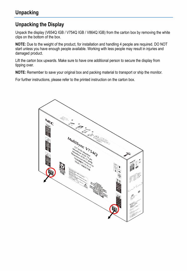
Unpacking
Unpacking the Display
Unpack the display (V654Q IGB / V754Q IGB / V864Q IGB) from the carton box by removing the white clips on the bottom of the box.
NOTE: Due to the weight of the product, for installation and handling 4 people are required. DO NOT start unless you have enough people available. Working with less people may result in injuries and damaged product.
Lift the carton box upwards. Make sure to have one additional person to secure the display from tipping over.
NOTE: Remember to save your original box and packing material to transport or ship the monitor.
For further instructions, please refer to the printed instruction on the carton box.

General Installation
This device cannot be used or installed without a mounting accessory for support. For proper installation it is strongly recommended to use a trained, NEC authorized service person. Failure to follow NEC standard mounting procedures could result in damage to the equipment or injury to the user or installer. Product warranty does not cover damage caused by improper installation. Failure to follow these recommendations could result in voiding the warranty
Mounting
For customer:
CAUTION
DO NOT mount the monitor yourself. For proper installation it is strongly recommended to use a trained, qualified technician. Please contact your supplier, as they may be able to provide a list of qualified installation professionals. Mounting on a wall or ceiling and hiring a technician is the customer’s responsibility.
Maintenance
• Periodically check for looses screws, gaps, distortions, or other problems that may occur with the mounting equipment. If a problem is detected, please refer to qualified personnel for service.
• Regularly check the mounting location for signs of damage or weakness that may occur over time.
DO NOT block ventilated openings with mounting accessories or other accessories.
For NEC Qualified Personnel:
Stability Hazard.
The device may fall, causing serious personal injury or death. To prevent injury, this device must be securely attached to the floor/wall in accordance with the installation instructions. Carefully inspect the location where the unit is to be mounted. Not all walls or ceilings are capable of supporting the weight of the unit. Weight of this monitor is mentioned in Specification (see 65” InfinityBoard 2.0 on page 21, 75” InfinityBoard 2.0 on page 25, 86” InfinityBoard 2.0 on page 30). Product warranty does not cover damage caused by improper installation, remodeling, or natural disasters. Failure to comply with these recommendations could result in voiding the warranty.
To ensure safe installation, use two or more brackets to mount the unit. Mount the unit to at least two points on the installation location.
NOTE: To achieve optimum performance of touch technology, monitor must be correctly leveled. Only straight upright and titled back position of the monitor is acceptable. Monitor tilted to front will result in convex position of the glass and might negatively influence the touch performance.
For further instructions, please refer to standard user’s manual of the base model monitors V654Q, V754Q and V864Q.
Convex position
of glass

InfinityBoard Assembly Instruction
Mounting of Speakers & Camera
PART QUANTITY DESCRIPTION
A 1 Display
B 2 Speaker
C 1 Camera
D 1 1/4“ x 16 Screw
E 1 Washer
F 12 M4 x 12 Countersunk Screw
G 6 Speaker Bracket
H 12 3.5 x 6 Screw
I 2 Back Plate
J 4 M4 x 12 Screw
K 4 Washer
L 1 Mounting Bracket
M 1 USB 3.0 Angled Cable (2m)
B
G
F
1
C
D
E
M
2B
H
I
3 NOTE: Do not torque screw D
(picture 2) too tight. That way you
will still be able to mechanically
adjust the position of the camera
after the installation.
Connect the 2 m USB cable
supplied with the Huddly camera to
USB-C on the camera. Guide the
camera cable gently through the
long opening in the back plate of the
speaker (picture 3).
B

InfinityBoard Assembly Instruction
Mounting of Speakers & Camera
4
A
A
L
J
K
X
5 AB
NOTE:
Before mounting the speaker
bracket, please remove screw X
(picture 4) from rear side of display.
After mounting the speaker bracket
to the display, hook the speaker
from the top into the bracket
attached to the display. Gently push
the speaker down until the speaker
sits flush with the display.
The side mounted speakers can be
attached to the monitor after the
monitor is mounted to the wall or
trolley.

InfinityBoard Assembly Instruction
Installing the OPS Slot-in PC
NOTE: Make sure to write down the Windows 10 license code which can be found on the rear-
side of the OPS slot-in PC.
Follow the instruction described in picture 6 to 9:
1. Turn off the main power switch on the monitor.
2. Remove the attached slot cover by unscrewing the installed screws (picture 6), sliding to right
(picture 7) and moving up (picture 8).
3. Insert the OPS PC into the monitor and fix it with the removed screws (picture 9).
NOTE: Do not apply excessive force to manipulate the OPS PC before fixing it with screws. Make
sure that the OPS PC is inserted into the slot in the correct orientation.
CAUTION: Ensure the OPS PC is attached by the removed screws. Otherwise, the OPS PC may
fall out and expose you to danger.
(Recommended Fasten Force: 139 - 189N•cm).
A
6 87 9

InfinityBoard Assembly Instruction
Connecting Cables
NOTE: Do not connect or disconnect cables when turning on the monitor’s main power or other external equipment’s power as this may result in a loss of image.
NOTE: Do not use an attenuating (built-in resistor) audio cable. Use an audio cable without a built-in resistor. Using an audio cable with a built-in resistor will lower the sound level.
Before making connections:
• Turn off the device’s power before connecting it to the monitor.
• Refer to the device’s user manual for available connection types and instructions for the device.
• We recommend turning off the monitor’s main power before connecting or disconnecting a USB storage device or a microSD memory card to avoid data corruption.
1. Enable the USB hub: Use the short 10 cm USB cable
supplied with the monitor. Connect USB cable from USB
Type-B input marked with “Hub” (located above external
speaker terminals) to USB Type-A input marked with “USB 1”
on the side of the monitor. The red LED on the USB hub will
light up.
NOTE: To enable USB 3.0 on USB ports on the USB hub you
need to connect the 3 m USB cable supplied with the monitor to
one of the USB 3.0 ports of the OPS slot-in PC.
NOTE: When connected to an external PC, use the 3 m USB
cable supplied with the monitor. Connect USB cable from USB
Type-B input marked with “Hub” to USB Type-A input of the
external PC.
2. Connect the external speakers: Connect the audio cables to
the terminals on each speaker and to the speaker terminals
on the side of the InfinityBoard. Red terminal is plus (+) and
black terminal is minus (-).
3. Activate the external speakers: Push the button
“Internal/External speaker switch” below the speaker terminals
on the monitor to enable the external speakers.
7HUB
TOUCH
Internal/External speaker switch
EXTERNAL SPEAKER
TERMINAL
USB 1

InfinityBoard Assembly Instruction
4. Enable touch: When used with an OPS slot-in PC no external
USB cable is needed to activate touch.
NOTE: When connected to an external PC, use the 3 m USB
cable supplied with the monitor. Connect from USB Type-B input
marked with “Touch” to USB Type-A input of the external PC.
7HUB
TOUCH
Internal/External speaker switch
EXTERNAL SPEAKER
TERMINAL
USB 1
Picture of USB hub and speaker cabling

InfinityBoard Assembly Instruction
5. Connect the Huddly camera:
Connect the 2 m USB cable
supplied with the Huddly
camera from USB-C of the
camera to one of the USB 3.0
ports of the OPS slot-in PC.
NOTE: For use with external PC,
NEC can provide Huddly certified
USB extension cables to connect the
Huddly camera to the external PC.
USB 3.0

Setup the OPS Slot-in PC
Installation of Windows 10 Professional
1. Follow the Windows installation process.
2. To activate Windows, please use the Windows 10 license code which can be found on the rear side of the OPS slot-in PC.
3. Once you are ready, you will see the following start screen.
4. Pre-installed applications:
FlatFrog Whiteboard
MS OneNote
Mosaic Connect for wireless screen sharing
Huddly App for camera control
Hoylu Suite (single user license)
>> For further information please visit: https://hoylu.com/ or contact [email protected].

Setup the OPS Slot-in PC
Select the Speakers
1. Open the “Sound” settings in Windows by clicking on the speaker icon in the Windows task bar.
2. Open the “Playpack” tab in the “Sound” settings and select the V654Q, V754Q or V864Q monitor as “Default Device”. This will enable the side-mounted passive speakers.
NOTE: We recommend to disable all other speaker options.
Select a Microphone
NOTE: The 65”, 75” & 86” InfinityBoards 2.0 / 2.1 do not have a built-in microphone. We recommend to choose the right microphone depending on the room size, room acoustics and number of people in the room.
• Open the “Recording” tab in the “Sound” settings and select the external microphone of your choice.
V754Q

Troubleshooting
1. Slow writing performance
Make sure the OPS PC is running UHD resolution with 60Hz
OSD MENU SETTING:
• ADVANCED OPTION1 » OPTION SETTINGS
• SLOT2 CH SETTING » CH1
• SLOT2 CH SELECT » DPORT
2. Bad sound quality from side-mounted speakers
Make sure the following setting is enabled in the OSD
OSD MENU SETTING:
• ADVANCED OPTION1 » OPTION SETTINGS
• LONG CABLE COMP » AUDIO » DIGITAL
3. OPS slot-in PC doesn’t shut down when monitor is set to stand-by mode
Make sure the following setting is enables in the OSD
OSD MENU SETTING:
• ADVANCED OPTION1 » OPTION SETTINGS
• AUTO OFF » change to ON
4. Monitor doesn’t go to stand-by mode after OPS slot-in PC was shutting down
Make sure the following setting is enables in the OSD
OSD MENU SETTING:
• DISPLAY PROTECTION » POWER SAVE
• AUTO STANDBY » ENABLE and set a time period
5. The touch panel does not respond
• Make sure that PIP (picture in picture), PBP (picture by picture), TILE MATRIX, ROTATE and ZOOM are not selected.
• Check the input signal setting.
• The touch panel function does not support the media player function. Please use the remote control to set the media player while the touch panel function is working.
• Make sure that TOUCH POWER setting in USB in CONTROL is “ON”.
• Check the PC SOURCE setting in USB in CONTROL.
Using slot 2 type PC:
Make sure that PC SOURCE is AUTO or OPTION, and the input signal is set to OPTION.
Make sure the slot 2 type PC is connected properly.
Using external computer:
Make sure that PC SOURCE is AUTO or EXTERNAL PC, and the input signal is set to which supplied by the connected computer.
Make sure the USB cable is connected properly.

Troubleshooting
• The touch panel function may not work depending on the specification of an external computer and connecting method.
• If the TOUCH POWER setting in USB in CONTROL is set to “ON”, change it to “OFF” and back to “ON” again after a moment.
• When using touch function at the display edge, there may be a slight gap between touch position on the screen and where you touched. It is the specification and not a failure of product.
6. The USB hub only supports USB 2.0
To enable USB 3.0 on the USB hub you need to connect the 3 m USB cable supplied with the monitor to one of the USB 3.0 ports of the OPS slot-in PC.

Specifications – 65” InfinityBoard 2.0 / 2.1
65” InfinityBoard 2.0
65” InfinityBoard 2.1

Specifications – 65” InfinityBoard 2.0 / 2.1

Specifications – 65” InfinityBoard 2.0 / 2.1
65” InfinityBoard 2.0
65” InfinityBoard 2.1

Specifications – 65” InfinityBoard 2.0 / 2.1
NOTE: Technical specifications are subject to change without notice.

Specifications – 75” InfinityBoard 2.0 / 2.1
75” InfinityBoard 2.0
75” InfinityBoard 2.1

Specifications – 75” InfinityBoard 2.0 / 2.1

Specifications – 75” InfinityBoard 2.0 / 2.1
75” InfinityBoard 2.0
75” InfinityBoard 2.1

Specifications – 75” InfinityBoard 2.0 / 2.1
NOTE: Technical specifications are subject to change without notice.

Specifications – 86” InfinityBoard 2.0 / 2.1
86” InfinityBoard 2.0
86” InfinityBoard 2.1

Specifications – 86” InfinityBoard 2.0 / 2.1

Specifications – 86” InfinityBoard 2.0 / 2.1
86” InfinityBoard 2.0
86” InfinityBoard 2.1

Specifications – 86” InfinityBoard 2.0 / 2.1
NOTE: Technical specifications are subject to change without notice.

Manufacturer’s Recycling and Energy Information
NEC DISPLAY SOLUTIONS is strongly committed to environmental protection and sees recycling as one of the company’s top priorities in trying to minimize the burden placed on the environment. We are engaged in developing environmentally-friendly products, and always strive to help define and comply with the latest independent standards from agencies such as ISO (International Organisation for Standardization) and TCO (Swedish Trades Union).
Disposing of your old NEC product
The aim of recycling is to gain an environmental benefit by means of re-use, upgrading, reconditioning or reclamation of material. Dedicated recycling sites ensure that environmentally harmful components are properly handled and securely disposed. To ensure the best recycling of our products, NEC DISPLAY SOLUTIONS offers a variety of recycling procedures and gives advice on how to handle the product in an environmentally sensitive way, once it has reached the end of its life.
All required information concerning the disposal of the product and country-specific information on recycling facilities can be found on our following websites:
https://www.nec-display-solutions.com/p/greenvision/en/greenvision.xhtml (in Europe),
https://www.nec-display.com (in Japan) or
https://www.necdisplay.com (in USA).
Energy Saving
This monitor features an advanced energy saving capability. When a Display Power Management signal is sent to the monitor, the Energy Saving mode is activated. The monitor enters a single Energy Saving mode.
For additional information visit:
https://www.necdisplay.com/ (in USA)
https://www.nec-display-solutions.com/ (in Europe)
https://www.nec-display.com/global/index.html (Global)
For ErP requirement/For ErP (Network standby) requirement:
Except for the conditions below: The monitor is using an Option Board.
INPUT DETECT is set to a setting except for NONE.
USB POWER is set to ON. DisplayPort in the TERMINAL SETTINGS is set to MST.
Power consumption (Glowing amber): 2.0 W or less (with 1 port connection)/3.0 W or less (with all ports connection). Time for power management function: 10 sec. (Default setting)
Power consumption (Blinking amber): 0.5 W or less.
Time for power management function: 3 min. (Default setting) (Except for a condition that the monitor has plural signal inputs.)

Manufacturer’s Recycling and Energy Information
WEEE Mark (European Directive 2012/19/EU and amendments)
Disposing of your used product: In the European Union
EU-wide legislation as implemented in each Member State requires that used electrical and electronic products carrying the mark (left) must be disposed of separately from normal household waste. This includes monitors and electrical accessories, such as signal cables or power cords. When you dispose of such products, please follow the guidance of your local authority or ask the shop where you purchased the product, or if applicable, follow applicable legislation or agreement you may have. The mark on electrical and electronic products may only apply to the current European Union Member States.
Outside the European Union
If you wish to dispose of used electrical and electronic products outside the European Union, please contact your local authority and ask for the correct method of disposal.
For EU: The crossed-out wheeled bin implies that used batteries should not be put to the general household waste! There is a separate collection system for used batteries, to allow proper treatment and recycling in accordance with legislation.
According to EU directive 2006/66/EC and amendments, the battery can’t be disposed improperly. The battery shall be separated to collect by local service.