Embed Size (px)
Citation preview
IntroductionThe X-NUCLEO-STMODA1 provides an easy way to expand your STM32 Nucleo board with the STMod+ connector, whichallows interaction with the new set of STM32 Nucleo development boards using this connector. It provides an easy way toevaluate the STMod+ board solution together with other STM32 Nucleo boards.
The STMod+ is a 2x10-pin connector providing a set of interfaces such as SPI, UART, I²C and other functions such as RESET,INTERRUPT, ADC, PWM and general purpose I/Os. The X-NUCLEO-STMODA1 has a female STMod+ connector with 2 mmpitch.
The X-NUCLEO-STMODA1 expansion board is equipped with a set of jumpers for the added flexibility of allowing you to alsouse the board with the STM32 B-L475E-IOT01A discovery kit node board.
Figure 1. X-NUCLEO-STMODA1 expansion board
Getting started with the X-NUCLEO-STMODA1 expansion board for STM32 Nucleo
UM2400
User manual
UM2400 - Rev 1 - April 2018For further information contact your local STMicroelectronics sales office.
www.st.com

1 Getting started
1.1 Board overviewThe X-NUCLEO-STMODA1 expansion board key features are:• Extend the STM32 Nucleo development board power supply to the connected STMod+ daughter board,
since the current limitation are related to STM32 Nucleo development board capability, please refer toUM1724 for details
• 15 jumpers to manage USART, I²C and SPI connections• Compatible with Arduino UNO V3 connector• Compatible with STM32 Nucleo boards• RoHS compliant
1.2 Hardware and software requirementsTo use STM32 Nucleo development boards with the X-NUCLEO-STMODA1 expansion board, the followingsoftware and hardware are required:• a Windows PC (XP, Vista 7, Win 8, Win 10 ) to install the software package• an STM32 Nucleo development board• a type A USB to mini-B USB cable to connect the STM32 Nucleo board to the PC• an IDE among
– IAR Embedded Workbench for ARM (EWARM)– Keil microcontroller development kit (MDK-ARM)– System Workbench for STM32 (SW4STM32)
• A daughter board to be connected at STMod+ connector, like the LTE modem in the P-L496G-CELL02discovery pack.
You can also mount the X-NUCLEO-STMODA1 on an STM32 B-L475E-IOT01A discovery kit node board viaArduino connectors, as shown below.
Figure 2. Cellular LTE board setup using the X-NUCLEO-STMODA1
UM2400Getting started
UM2400 - Rev 1 page 2/10

2 Hardware description and configuration
The figure below indicates the board connector and jumper positions.
Figure 3. X-NUCLEO-STMODA1 connector and jumper positions
Note: In cyan the Arduino connectors and in green the STMod+ connectors.The jumper settings allow you to modify the USART, I²C and SPI connections. The following table lists the jumperdefault settings.
Table 1. Jumper default settings
Jumper Default position Use
JP1 1-2 LEFT USART1/2 Selection (default USART2)
JP2 1-2 LEFT USART1/2 Selection (default USART2)
JP3 1-2 DOWN SPI/UART Selection (default UART)
JP4 1-2 DOWN SPI/UART Selection (default UART)
JP5 1-2 DOWN SPI/UART Selection (default UART)
JP6 ON Enable/Disable INT (default Enable)
JP7 ON Enable/Disable RESET (default Enable)
JP8 OFF Enable/Disable ADC (default Disable)
JP9 ON Enable/Disable PWM (default Enable)
JP10 OFF Enable/Disable GPIO1 (default Disable)
JP11 ON Enable/Disable GPIO2 (default Enable)
JP12 OFF Enable/Disable GPIO3 (default Disable)
JP13 ON Enable/Disable GPIO4 (default Enable)
JP14 ON Enable/Disable SPI_MISO (default Enable)
JP15 ON Enable/Disable SPI_MOSI (default Enable)
UM2400Hardware description and
configuration
UM2400 - Rev 1 page 3/10

3 Connectivity diagram
The table below shows the pin assignments and descriptions for the STMod+ connector.
Table 2. Pin assignments and descriptions
STMod+ Pin Function of the primary host mapped(1)
Description
1 SPIx_NSS / UARTy_CTS (2) Output / Input
2 SPIx_MOSIp / UARTy_TX (3) Output / Output
3 SPIx_MISOp / UARTy_RX Input / Input
4 SPIx_SCK / UARTy_RTS Output / Output
5 GND Ground Reference
6 +5 V Power supply
7 I2Cz_SCL Input / Output
8 SPIx_MOSIs (2) Output
9 SPIx_MISOs (4) Input / Output
10 I2Cz_SDA Input / Output
11 INT (6) Input
12 RESET Output
13 ADC Input
14 PWM Output
15 +5 V Power supply (5)
16 GND Ground Reference
17 GPIO Input / Output
18 GPIO (7) Input / Output
19 GPIO (7) Input / Output
20 GPIO (7) Input / Output
1. If two functions are provided on an STMod+ connector pin, you can connect two different I/O ports from STM32 and thefirmware will manage any conflicts. MOSIs means used in Serial Daisy Chained-SPI mode and MOSIp means used inParallel SPI mode. More alternate functions may be available from STM32, refer to the User manual of the host board andthe corresponding STM32 datasheet available on www.st.com
2. Instead of SPIx_NSS, a GPIO can be used as SPI Chip Select3. Pins 2 and 8 are the same SPIx_MOSI signals, but they must come from two different I/Os4. Pins 3 and 9 are the same SPIx_MISO signals, but they must come from two different I/Os5. Power Supply is Output or Input, depending on host / daughterboard configuration6. INT is an interrupt line7. GPIO ports with many alternate functions (like UART, I2C, SPI and analog inputs/outputs) are privileged to offer optimum
flexibility
UM2400Connectivity map
UM2400 - Rev 1 page 4/10
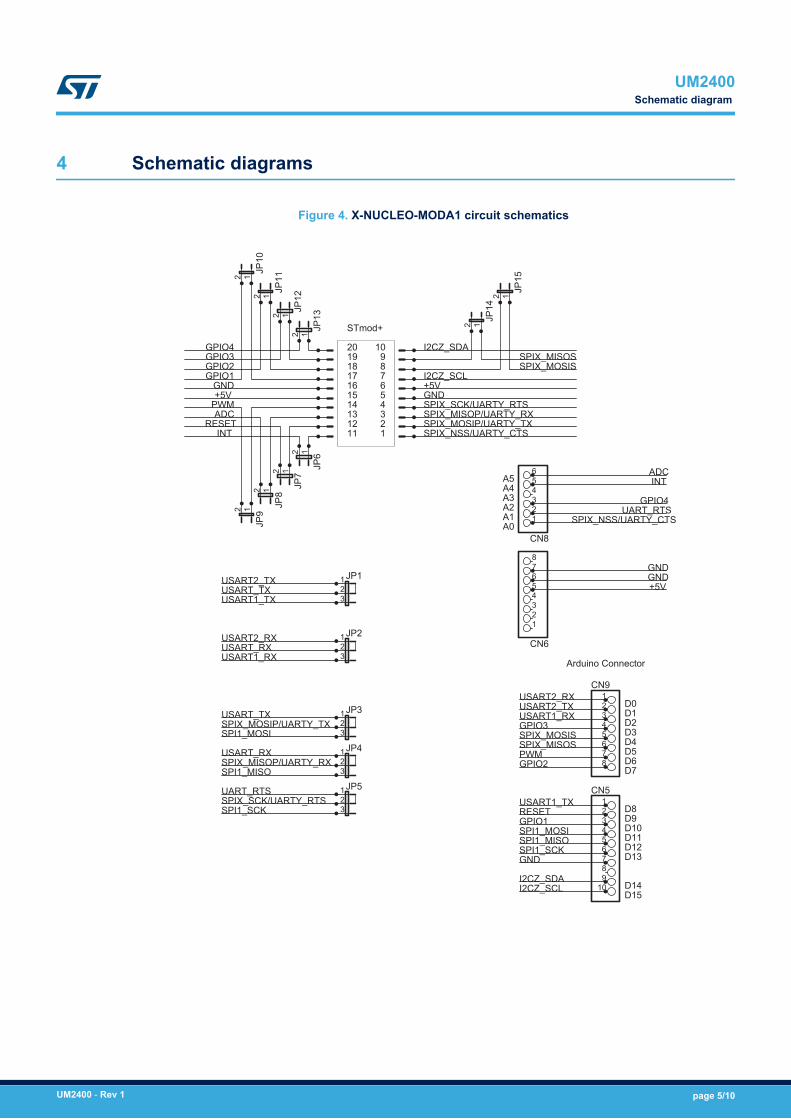
4 Schematic diagrams
Figure 4. X-NUCLEO-MODA1 circuit schematics
A0A1A2A3A4A5
D0D1D2D3D4D5D6D7
D8D9D10D11D12D13
D14D15
STmod+
Arduino Connector
CN6
12345678
CN8
123456
CN912345678
CN5123456789
10
JP1123
JP2123
JP3123
JP4123
JP5123
JP612
JP712
JP812
JP912
JP10
12
JP11
12
JP12
12
JP13
12
JP14
12
JP15
12
UART_RTS
UART_RTS
USART2_RX
USART2_RX
USART2_TX
USART2_TX
USART1_TX
USART1_TX
USART1_RX
USART1_RX
SPI1_MOSI
SPI1_MOSI
SPI1_MISO
SPI1_MISO
SPI1_SCK
SPI1_SCK
USART_TX
USART_TX
USART_RX
USART_RX
SPIX_NSS/UARTY_CTS
SPIX_NSS/UARTY_CTS
SPIX_MOSIP/UARTY_TX
SPIX_MOSIP/UARTY_TX
SPIX_MISOP/UARTY_RX
SPIX_MISOP/UARTY_RX
SPIX_SCK/UARTY_RTS
SPIX_SCK/UARTY_RTS
GNDGND
GNDGND
GND
+5V+5V
+5V
I2CZ_SCL
I2CZ_SCL
I2CZ_SDA
I2CZ_SDA
SPIX_MISOS
SPIX_MISOS
SPIX_MOSIS
SPIX_MOSIS
INT
INT
RESET
RESET
ADC
ADC
PWM
PWM
GPIO4
GPIO4
GPIO3
GPIO3
GPIO2
GPIO2
GPIO1
GPIO1
123456789
10
11121314151617181920
UM2400Schematic diagram
UM2400 - Rev 1 page 5/10

Revision history
Table 3. Document revision history
Date Version Changes
17-Apr-2018 1 Initial release.
UM2400
UM2400 - Rev 1 page 6/10

Contents
1 Getting started . . . . . . . . . . . . . . . . . . . . . . . . . . . . . . . . . . . . . . . . . . . . . . . . . . . . . . . . . . . . . . . . . . . .2
1.1 Board overview . . . . . . . . . . . . . . . . . . . . . . . . . . . . . . . . . . . . . . . . . . . . . . . . . . . . . . . . . . . . . . . . 2
1.2 Hardware and software requirements . . . . . . . . . . . . . . . . . . . . . . . . . . . . . . . . . . . . . . . . . . . . . 2
2 Hardware description and configuration . . . . . . . . . . . . . . . . . . . . . . . . . . . . . . . . . . . . . . . . . . .3
3 Connectivity diagram . . . . . . . . . . . . . . . . . . . . . . . . . . . . . . . . . . . . . . . . . . . . . . . . . . . . . . . . . . . . . .4
4 Schematic diagrams . . . . . . . . . . . . . . . . . . . . . . . . . . . . . . . . . . . . . . . . . . . . . . . . . . . . . . . . . . . . . . .5
Revision history . . . . . . . . . . . . . . . . . . . . . . . . . . . . . . . . . . . . . . . . . . . . . . . . . . . . . . . . . . . . . . . . . . . . . . . .6
UM2400Contents
UM2400 - Rev 1 page 7/10
List of tablesTable 1. Jumper default settings. . . . . . . . . . . . . . . . . . . . . . . . . . . . . . . . . . . . . . . . . . . . . . . . . . . . . . . . . . . . . . . . 3Table 2. Pin assignments and descriptions . . . . . . . . . . . . . . . . . . . . . . . . . . . . . . . . . . . . . . . . . . . . . . . . . . . . . . . . 4Table 3. Document revision history . . . . . . . . . . . . . . . . . . . . . . . . . . . . . . . . . . . . . . . . . . . . . . . . . . . . . . . . . . . . . . 6
UM2400List of tables
UM2400 - Rev 1 page 8/10
List of figuresFigure 1. X-NUCLEO-STMODA1 expansion board . . . . . . . . . . . . . . . . . . . . . . . . . . . . . . . . . . . . . . . . . . . . . . . . . . 1Figure 2. Cellular LTE board setup using the X-NUCLEO-STMODA1 . . . . . . . . . . . . . . . . . . . . . . . . . . . . . . . . . . . . . 2Figure 3. X-NUCLEO-STMODA1 connector and jumper positions. . . . . . . . . . . . . . . . . . . . . . . . . . . . . . . . . . . . . . . . 3Figure 4. X-NUCLEO-MODA1 circuit schematics . . . . . . . . . . . . . . . . . . . . . . . . . . . . . . . . . . . . . . . . . . . . . . . . . . . 5
UM2400List of figures
UM2400 - Rev 1 page 9/10

IMPORTANT NOTICE – PLEASE READ CAREFULLY
STMicroelectronics NV and its subsidiaries (“ST”) reserve the right to make changes, corrections, enhancements, modifications, and improvements to STproducts and/or to this document at any time without notice. Purchasers should obtain the latest relevant information on ST products before placing orders. STproducts are sold pursuant to ST’s terms and conditions of sale in place at the time of order acknowledgement.
Purchasers are solely responsible for the choice, selection, and use of ST products and ST assumes no liability for application assistance or the design ofPurchasers’ products.
No license, express or implied, to any intellectual property right is granted by ST herein.
Resale of ST products with provisions different from the information set forth herein shall void any warranty granted by ST for such product.
ST and the ST logo are trademarks of ST. All other product or service names are the property of their respective owners.
Information in this document supersedes and replaces information previously supplied in any prior versions of this document.
© 2018 STMicroelectronics – All rights reserved
UM2400
UM2400 - Rev 1 page 10/10