Embed Size (px)
Citation preview

Orthopantomograph® OP200Orthoceph® OC200
User Manual & Technical Specifications
5139539-100 rev. 2
ENGLISH


Copyright Code: 5139539-100 rev 2 Date: 14 September 2012Document code: D500318 rev 2
Copyright © 09/2012 by PaloDEx Group Oy. All rightsreserved.
Manufactured by Instrumentarium Dental, PaloDEx Group OyP.O. Box 20FI-04301 TuusulaFINLANDTel. +358 45 7882 2000Fax. +358 45 7882 2506
Orthopantomograph® and Orthoceph® are registered trademarks ofInstrumentarium Dental. U.S. patents 6,731,717, 6,829,326 andUSRE41197. Finnish patents 114383. Windows® is trademark ofMicrosoft Corporation in the United States of America and othercountries. Pentium® is a registered trademark of Intel Corporation.Iomega® Jaz® is a registered trademark of Iomega Corp.
Documentation, trademark and the software are copyrighted with allrights reserved. Under the copyright laws the documentation may notbe copied, photocopied, reproduced, translated, or reduced to anyelectronic medium or machine readable form in whole or part, withoutthe prior written permission of Instrumentarium Dental.
The original language of this manual is English.
Instrumentarium Dental reserves the right to make changes inspecification and features shown herein, or discontinue the productdescribed at any time without notice or obligation. Contact yourInstrumentarium Dental representative for the most currentinformation.
For service, contact your local distributor.

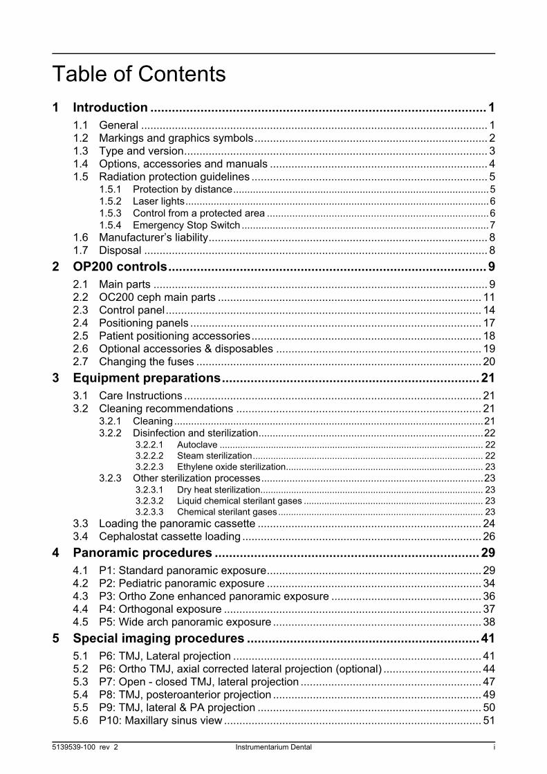
Table of Contents
1 Introduction .............................................................................................. 11.1 General ................................................................................................................. 11.2 Markings and graphics symbols............................................................................ 21.3 Type and version................................................................................................... 31.4 Options, accessories and manuals ....................................................................... 41.5 Radiation protection guidelines ............................................................................. 5
1.5.1 Protection by distance...........................................................................................51.5.2 Laser lights............................................................................................................61.5.3 Control from a protected area ...............................................................................61.5.4 Emergency Stop Switch ........................................................................................7
1.6 Manufacturer’s liability........................................................................................... 81.7 Disposal ................................................................................................................ 8
2 OP200 controls......................................................................................... 92.1 Main parts ............................................................................................................. 92.2 OC200 ceph main parts ...................................................................................... 112.3 Control panel....................................................................................................... 142.4 Positioning panels ............................................................................................... 172.5 Patient positioning accessories........................................................................... 182.6 Optional accessories & disposables ................................................................... 192.7 Changing the fuses ............................................................................................. 20
3 Equipment preparations........................................................................ 213.1 Care Instructions ................................................................................................. 213.2 Cleaning recommendations ................................................................................ 21
3.2.1 Cleaning ..............................................................................................................213.2.2 Disinfection and sterilization................................................................................22
3.2.2.1 Autoclave ....................................................................................................... 223.2.2.2 Steam sterilization.......................................................................................... 223.2.2.3 Ethylene oxide sterilization............................................................................. 23
3.2.3 Other sterilization processes...............................................................................233.2.3.1 Dry heat sterilization....................................................................................... 233.2.3.2 Liquid chemical sterilant gases ...................................................................... 233.2.3.3 Chemical sterilant gases ................................................................................ 23
3.3 Loading the panoramic cassette ......................................................................... 243.4 Cephalostat cassette loading .............................................................................. 26
4 Panoramic procedures .......................................................................... 294.1 P1: Standard panoramic exposure...................................................................... 294.2 P2: Pediatric panoramic exposure ...................................................................... 344.3 P3: Ortho Zone enhanced panoramic exposure ................................................. 364.4 P4: Orthogonal exposure .................................................................................... 374.5 P5: Wide arch panoramic exposure .................................................................... 38
5 Special imaging procedures ................................................................. 415.1 P6: TMJ, Lateral projection ................................................................................. 415.2 P6: Ortho TMJ, axial corrected lateral projection (optional) ................................ 445.3 P7: Open - closed TMJ, lateral projection ........................................................... 475.4 P8: TMJ, posteroanterior projection .................................................................... 495.5 P9: TMJ, lateral & PA projection ......................................................................... 505.6 P10: Maxillary sinus view .................................................................................... 51
5139539-100 rev 2 Instrumentarium Dental i
6 Cephalometric procedures (optional) .................................................. 556.1 P11: Cephalo lateral projection ........................................................................... 556.2 P12: Cephalo posterior-anterior (PA) projection ................................................. 586.3 P7: Axial view of the mandible exposure ............................................................ 596.4 P5: Rewerse Towne projection exposure ........................................................... 606.5 P5: Waters view exposure .................................................................................. 616.6 P7: Carpus View exposure (optional).................................................................. 626.7 P13: Ortho Trans mandible exposure (optional) ................................................. 636.8 P14: Ortho Trans maxilla exposure (optional)..................................................... 63
7 Imaging technique ................................................................................. 657.1 Recommended film & screen combinations........................................................ 657.2 Automatic exposure control (AEC)...................................................................... 657.3 Exposure technique factors................................................................................. 667.4 Manual mode ...................................................................................................... 677.5 Test mode ........................................................................................................... 697.6 Film processing ................................................................................................... 697.7 Measurements from the image ........................................................................... 70
8 Special features...................................................................................... 718.1 Quality assurance ............................................................................................... 718.2 Exposure counter ................................................................................................ 728.3 Preventive maintenance reminder ...................................................................... 738.4 Ortho ID film marking .......................................................................................... 738.5 OP200 CR model for computerized radiography ................................................ 738.6 Free selection of kV and mA............................................................................... 74
9 Understanding the OP200 radiograph ................................................. 75
10 Failure diagnostics ................................................................................ 7710.1 Failure messages................................................................................................ 7710.2 kV display............................................................................................................ 7710.3 mA display........................................................................................................... 7710.4 Time display ........................................................................................................ 7810.5 Resetting failure .................................................................................................. 7810.6 Multiple failure codes .......................................................................................... 79
11 Diagnosing image quality problems .................................................... 8111.1 Patient positioning............................................................................................... 8111.2 Film density and contrast .................................................................................... 8311.3 Artefacts .............................................................................................................. 8511.4 Unit operation...................................................................................................... 87
12 How to use the user programming mode .......................................... 8912.1 General ............................................................................................................... 8912.2 Installation & unit configuration programs .......................................................... 8912.3 Programs affecting to image quality................................................................... 9012.4 Other Pr programs .............................................................................................. 9012.5 How to use the user programming mode ............................................................ 91
13 User program features........................................................................... 9313.1 PR 50 LAY: linear tomography image layer (optional) ........................................ 9313.2 PR 51 PUS: power up setting ............................................................................. 95
ii Instrumentarium Dental 5139539-100 rev 2

13.3 PR 52 GCO and PR 52 PCO: constant contrast & density settings.................................................................... 96
13.4 PR 53 NOR: resume normal settings................................................................ 10013.5 PR 54 ARN: rotating unit autoreturn ................................................................. 10113.6 PR 55 HUP: cassette holder autolift.................................................................. 10113.7 PR 56 HLI: cassette holder vertical limit ........................................................... 10213.8 PR 57 HON: Cassette lift side........................................................................... 10313.9 PR 58 CON: vertebrae shadow compensation ................................................. 10413.10 PR 59 PSE: preventative maintenance reminder ............................................ 10613.11 PR 60 BEP: panel beep................................................................................... 10613.12 PR 61 CLC: clear exposure counter ................................................................ 10713.13 PR 62 ERR: last failure code........................................................................... 10713.14 Pr 65 doS: dose / time display selection.......................................................... 10813.15Pr 66 COU: Exposure counters ........................................................................ 109
14 User's statement .................................................................................. 111
15 Technical specifications...................................................................... 11715.1 Electromagnetic Compatibility (EMC) tables..................................................... 123
16 Maintenance ......................................................................................... 12716.1 Maintenance Schedule...................................................................................... 12716.2 Monthly Inspection by User............................................................................... 12716.3 Preventative Maintenance Reminder ................................................................ 127
5139539-100 rev 2 Instrumentarium Dental iii

iv Instrumentarium Dental 5139539-100 rev 2
1 Introduction
1 Introduction
1.1 GENERAL
INSTRUMENTARIUM DENTAL® Orthopantomograph® OP200panoramic unit is a software controlled diagnostic panoramic dental x-ray equipment for producing high quality images of dentition, TM-jointsand skull. Anatomical details will be displayed on the film magnifiednominally by 30%.
The Orthopantomograph® OP200 can perform the followingprocedures:
• Standard panoramic exposure• Pediatric panoramic exposure• Wide arch panoramic exposure • Ortho Zone enhanced panoramic exposure• Orthogonal panoramic exposure• TMJ, lateral projection or• Ortho TMJ axial corrected lateral projection (optional)• TMJ, lateral projection jaw closed and open• TMJ, PA projection• TMJ, lateral and PA projection• Maxillary sinus
Your Orthopantomograph® OP200, model OP200 OT or OP200 CR,can be field upgraded at a later time to the Orthoceph® OC200 model.With this addition, high quality cephalometric exposures can also bemade.
NOTE!
OP200 must be installed according to the OP200 installation &Adjustments manual by a qualified technician. Only trained personnelshould be allowed to operate OP200.
In addition to the above mentioned procedures Orthoceph® OC200can perform the following cephalometric procedures:
• Lateral view• Postero-anterior and Antero-posterior views• Oblique projections• Townes, Waters, Caldwell, SMV, Carpus
Orthopantomograph® OP200 or Orthoceph® OC200 can also be fieldupgraded to the OP/OC200 OT model. OP200 with the Ortho Transoption can do the following linear tomographic procedures:
• Maxillary imaging in longitudinal and transversal views• Mandible imaging in longitudinal and transversal views
Digital imaging is possible with OP200 D and OC200 D models or byusing phosphor image plates with OP200 CR, OC200 CR, OP200 OT/CR and OC200 OT/CR models.
5139539-100 rev 2 Instrumentarium Dental 1
1 Introduction
As the manufacturer we strongly recommend that you read thismanual before taking the unit into use.
1.2 MARKINGS AND GRAPHICS SYMBOLS
The following markings are used in this manual:
NOTE!
Contains useful information for the reader about the unit and its use.
CAUTION!
Contains important instructions. If these instructions are not observed,malfunction of the unit or damage to the unit or other property mayoccur.
WARNING!
Contains warnings and instructions about the safety of the unit. Ifthese warnings are not respected, serious risks and injury may becaused to the patient and operator.
The following symbols are used in the OP200.
Radiographic control
Protective earth (ground)
Type B equipment
Dangerous voltage
On (Power)
Off (Power)
Attention, consult accompanying documents
If the unit has CE-marking it is CE-marked according to the Medical Device Directive 93/42/EEC.
2 Instrumentarium Dental 5139539-100 rev 2
1 Introduction
1.3 TYPE AND VERSION
The type and version of the OP200 are defined in the main label of theunit. The unit is class I, type B and with IP-20 protection.
Fig 1.1. Location of main label and CE mark
ETL symbol
This symbol indicates that the waste of electrical and electronic equipment must not be disposed as unsorted municipal waste and must be collected separately. Please contact an authorized representative of the manufacturer for information concerning the decommissioning of your equipment.
TYPE AND VERSION
OP200 short form for Orthopantomograph® OP200
OC200 short form for Orthoceph® OC200
a type of the x-ray tube insert which is originally utilized:
1 = Toshiba D-051S
b version number:
1 OP200 models starting from s/n 100 000
S indication of a "Special" version, marked only in products which have a non-standard modification
5139539-100 rev 2 Instrumentarium Dental 3
1 Introduction
For example, OP200-1-1 is: (OP200) Orthopantomograph® OP200 (-1) with Toshiba D-051S tube (-1) first version of OP200.
1.4 OPTIONS, ACCESSORIES AND MANUALS
The options are listed in the appendices. The accessories are listed insections 2.5 and 2.6. All standard items and approved accessories aresuitable for use within the patient environment.
WARNING!
This product itself complies IEC601-1-1 medical safety standard but inorder to the system incorporating also a PC to comply the standard,EITHER the PC has to be a medical PC OR the PC has to be locatedover 1,5 meters apart from the OP/OC200 unit. The installer and theuser of the system shall confirm that at least one of the aboverequirements is fulfilled. A PC is a medical one if it complies IEC 601-1standard and that is indicated in the accompanying documents of thePC.
NOTE!
To maintain safe and correct functioning of OP200, only the approvedaccessories may be used.
CAUTION!
Use of controls or adjustments or performance of procedures otherthan those specified herein may result in hazardous radiationexposure.
Following manuals and documents are shipped with the OP200:
• OP200 / OC200 User Manual & Technical Specifications• OP200 / OC200 Installation & Adjustments Manual
These manuals and future updates are available on request from themanufacturer.
4 Instrumentarium Dental 5139539-100 rev 2
1 Introduction
1.5 RADIATION PROTECTION GUIDELINES
X-ray equipment may cause injury if used improperly. The instructionscontained in this manual must be read and followed when operatingthe Orthopantomograph® OP200. All government and local regulationspertaining to radiation safety must be observed.
NOTE!
For USA: Many provisions of these regulations are based onrecommendations of the National Council on Radiation Protection andMeasurements. Recommendations for dental x-ray protection arepublished in NCRP Report #35 available from NCRP Publications,7910 Woodmont Avenue, Suite 1016, Bethesda, MD 20814.
Personal radiation monitoring and protective devices are available andrecommended for staff members. It is also recommended to providethe patient with a protective apron. Consult the physician before takingimages of pregnant patients.
WARNING!
Orthopantomograph® OP200 must not be used in rooms where anexplosion hazard exists. Equipment not suitable for use in thepresence of flammable mixtures.
OP200 with radiation protection in accordance with IEC601-1-3:1994.
1.5.1 Protection by distance
In all examinations the user of the x-ray equipment should wearprotective clothing. The operator does not need to be close to thepatient during normal use. The protection against stray radiation canbe achieved by using the hand switch not less than 2 m (7 ft.) from thefocal spot and the x-ray beam. Operator should maintain visiblecontact with the patient and technique factors. This allows immediatetermination of radiation by the release of the exposure button in theevent of a malfunction or disturbance.
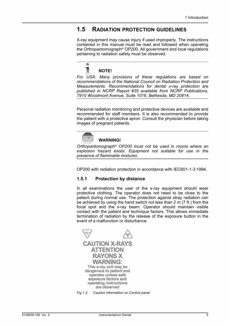
Fig 1.2. Caution information on Control panel
5139539-100 rev 2 Instrumentarium Dental 5

1 Introduction
1.5.2 Laser lights
1 FH-light
2 Mid-Sagittal light
3 Layer light
Fig 1.3. Laser light (CLASS 1 LASER PRODUCT). Max output 100µW.
1.5.3 Control from a protected area
The operator does not need to be close to the patient during normaluse. Control panel hand switch or optional remote hand switch can beused from an area protected from the x-ray beam. The fully extendedspiral cable length of the control panel hand switch is approx. 4 m / 13ft. The cable length of the remote hand switch (part #69961) isapproximately10 m / 32 ft.
6 Instrumentarium Dental 5139539-100 rev 2
1 Introduction
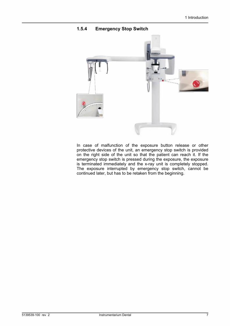
1.5.4 Emergency Stop Switch
In case of malfunction of the exposure button release or otherprotective devices of the unit, an emergency stop switch is providedon the right side of the unit so that the patient can reach it. If theemergency stop switch is pressed during the exposure, the exposureis terminated immediately and the x-ray unit is completely stopped.The exposure interrupted by emergency stop switch, cannot becontinued later, but has to be retaken from the beginning.
5139539-100 rev 2 Instrumentarium Dental 7
1 Introduction
1.6 MANUFACTURER’S LIABILITY
As a manufacturer we can only assume liability of safe and reliableoperation of this unit when
• OP200 unit installation was performed according to the OP200Installation & Adjustments Manual and
• OP200 Unit is used according to the OP200 User Manual• Maintenance and repairs are performed by a qualified
Orthopantomograph® OP200 Dealer and• Original or authorized spare parts are used
In order to quarantee maximal image quality for entire life time of thishigh performance imaging system, we suggest that a special imagequality assurance procedure (* and test object designed for imagequality assurance purposes is used (code 68795). Also werecommend qualified serviceman to check the unit to be in its originalcondition regarding electrical, radiation and mechanical safetyaccording to our maintenance program described in more details inmaintenance manual (code 61049) every year or after 2000 images.For more information please contact your local dealer.
*) According EN61223-3-4 and DIN 6868-151
If service on the unit is performed, a work order describing the typeand extent of repair must be provided by the service technician. Thismust contain information of changes of nominal data or work rangeperformed. The work order must furthermore indicate the date ofrepair, the name of the company concerned and a valid signature.User should keep this work order for future references.
1.7 DISPOSAL
Follow the local regulations on disposal of waste parts. OP200 has atleast the following parts that should be regarded as non-environmentalfriendly waste products:
– X-ray source assembly– All electronic circuits– Column counter weight (Pb)
8 Instrumentarium Dental 5139539-100 rev 2

2 OP200 controls
2 OP200 controls
2.1 MAIN PARTS
1 Cassette holder
2 Main support
3 Film cassette
4 Rotating unit
5 Head and Temple support
6 Primary collimator
7 Bite fork with rod
8 Chin rest
9 Handles
10 Patient positioning panel
11 Control panel
12 Exposure indicator lights
13 FH light height adjustment
14 Mirror
15 Base plate (optional)
12
34
56
789
10
11
12
13
14Optional Cephalostat
15
5139539-100 rev 2 Instrumentarium Dental 9
2 OP200 controls
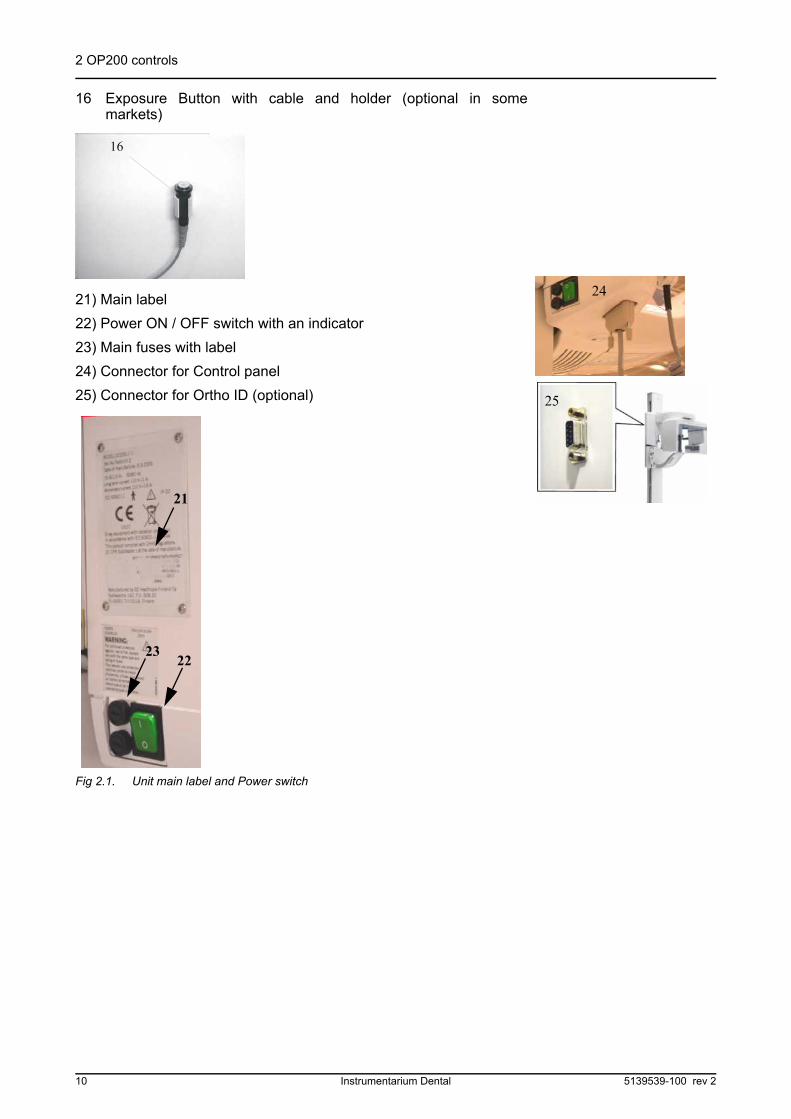
16 Exposure Button with cable and holder (optional in somemarkets)
21) Main label
22) Power ON / OFF switch with an indicator
23) Main fuses with label
24) Connector for Control panel
25) Connector for Ortho ID (optional)
Fig 2.1. Unit main label and Power switch
24
25
22
21
23
10 Instrumentarium Dental 5139539-100 rev 2

2 OP200 controls
2.2 OC200 CEPH MAIN PARTS
Fig 2.2. OC200 LL: Cephalostat mounted on the left side
Cephalostat arm
1 Cephalostat head
2 Cassette holder
3 Cassette retainer
4 Film cassette sizes: 18 x 24 cm and 24 x 30 cm or 8” x 10” and 10” x 12”
5 Guides for optional grid
6 Lock for axial rotation (see Fig 2.5)
7 Ear rods
8 Nasion support
9 Soft tissue scale display
10 Magnification scale
11 Ear holder brake
Fig 2.3. Head positioner, ear holdecassette holder
10
6
1
23
4
5
7
8
11
9
Fig 2.4. Lock for axial rotation Fig 2.5. Soft tissue scale display
5139539-100 rev 2 Instrumentarium Dental 11
2 OP200 controls
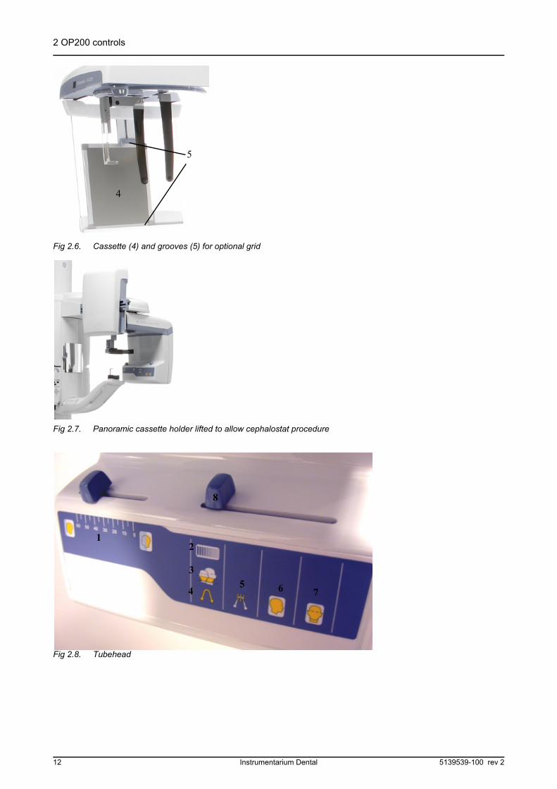
Fig 2.6. Cassette (4) and grooves (5) for optional grid
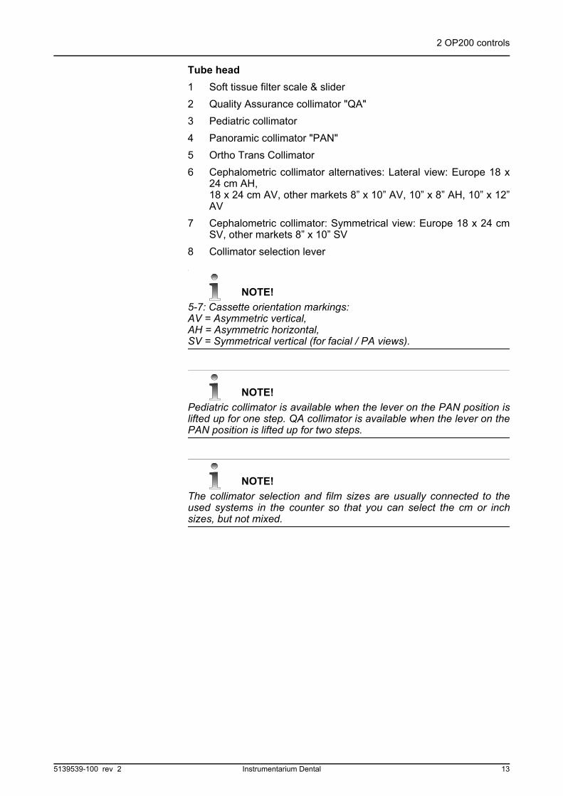
Fig 2.7. Panoramic cassette holder lifted to allow cephalostat procedure
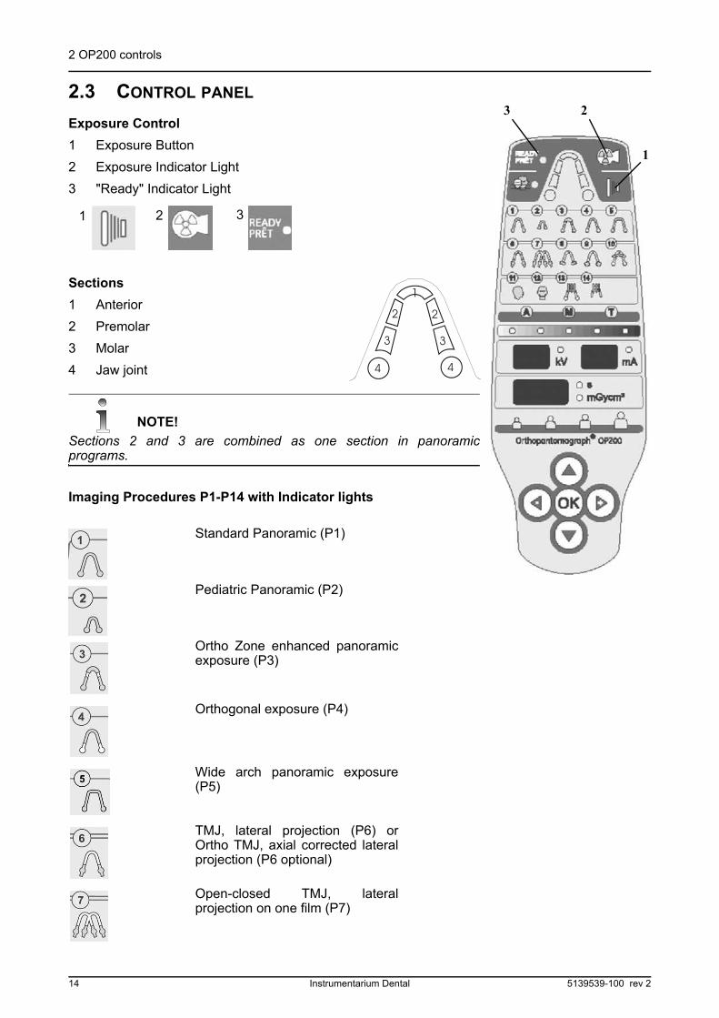
Fig 2.8. Tubehead
4
5
1
3
45 6 7
2
8
12 Instrumentarium Dental 5139539-100 rev 2
2 OP200 controls
Tube head
1 Soft tissue filter scale & slider
2 Quality Assurance collimator "QA"
3 Pediatric collimator
4 Panoramic collimator "PAN"
5 Ortho Trans Collimator
6 Cephalometric collimator alternatives: Lateral view: Europe 18 x24 cm AH, 18 x 24 cm AV, other markets 8” x 10” AV, 10” x 8” AH, 10” x 12”AV
7 Cephalometric collimator: Symmetrical view: Europe 18 x 24 cmSV, other markets 8” x 10” SV
8 Collimator selection lever
NOTE!
5-7: Cassette orientation markings: AV = Asymmetric vertical,AH = Asymmetric horizontal,SV = Symmetrical vertical (for facial / PA views).
NOTE!
Pediatric collimator is available when the lever on the PAN position islifted up for one step. QA collimator is available when the lever on thePAN position is lifted up for two steps.
NOTE!
The collimator selection and film sizes are usually connected to theused systems in the counter so that you can select the cm or inchsizes, but not mixed.
5139539-100 rev 2 Instrumentarium Dental 13
2 OP200 controls
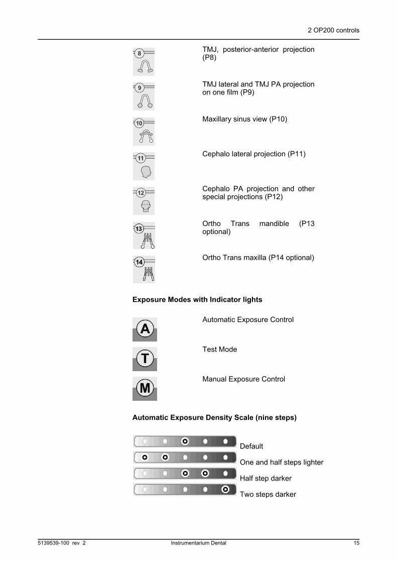
2.3 CONTROL PANEL
Exposure Control
1 Exposure Button
2 Exposure Indicator Light
3 "Ready" Indicator Light
Sections
1 Anterior
2 Premolar
3 Molar
4 Jaw joint
NOTE!
Sections 2 and 3 are combined as one section in panoramicprograms.
Imaging Procedures P1-P14 with Indicator lights
Standard Panoramic (P1)
Pediatric Panoramic (P2)
Ortho Zone enhanced panoramicexposure (P3)
Orthogonal exposure (P4)
Wide arch panoramic exposure(P5)
TMJ, lateral projection (P6) orOrtho TMJ, axial corrected lateralprojection (P6 optional)
Open-closed TMJ, lateralprojection on one film (P7)
3 2
1
1 32
14 Instrumentarium Dental 5139539-100 rev 2
2 OP200 controls
Exposure Modes with Indicator lights
Automatic Exposure Density Scale (nine steps)
Default
One and half steps lighter
Half step darker
Two steps darker
TMJ, posterior-anterior projection(P8)
TMJ lateral and TMJ PA projectionon one film (P9)
Maxillary sinus view (P10)
Cephalo lateral projection (P11)
Cephalo PA projection and otherspecial projections (P12)
Ortho Trans mandible (P13optional)
Ortho Trans maxilla (P14 optional)
Automatic Exposure Control
Test Mode
Manual Exposure Control
5139539-100 rev 2 Instrumentarium Dental 15
2 OP200 controls
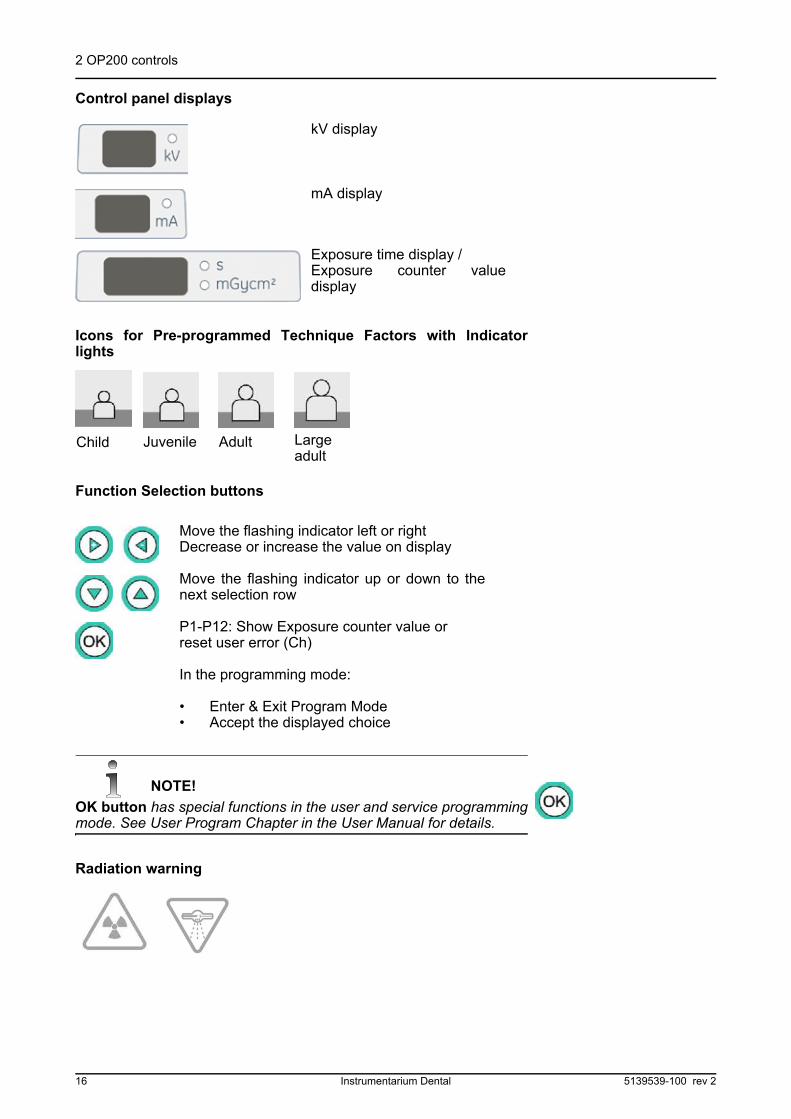
Control panel displays
Icons for Pre-programmed Technique Factors with Indicatorlights
Function Selection buttons
NOTE!
OK button has special functions in the user and service programmingmode. See User Program Chapter in the User Manual for details.
Radiation warning
kV display
mA display
Exposure time display / Exposure counter valuedisplay
Move the flashing indicator left or rightDecrease or increase the value on display
Move the flashing indicator up or down to thenext selection row
P1-P12: Show Exposure counter value or reset user error (Ch)
In the programming mode:
• Enter & Exit Program Mode• Accept the displayed choice
Child Juvenile Adult Largeadult
16 Instrumentarium Dental 5139539-100 rev 2
2 OP200 controls
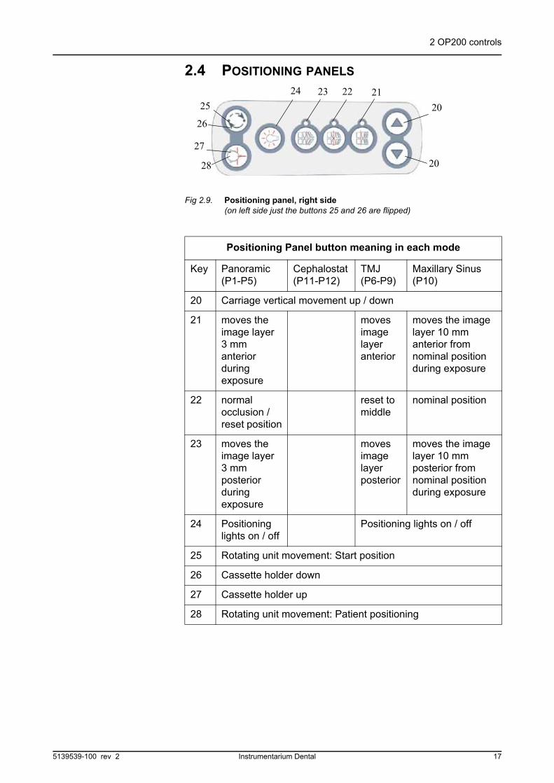
2.4 POSITIONING PANELS
Fig 2.9. Positioning panel, right side (on left side just the buttons 25 and 26 are flipped)
Positioning Panel button meaning in each mode
Key Panoramic (P1-P5)
Cephalostat (P11-P12)
TMJ (P6-P9)
Maxillary Sinus (P10)
20 Carriage vertical movement up / down
21 moves the image layer 3 mm anterior during exposure
moves image layer anterior
moves the image layer 10 mm anterior from nominal position during exposure
22 normal occlusion / reset position
reset to middle
nominal position
23 moves the image layer 3 mm posterior during exposure
moves image layer posterior
moves the image layer 10 mm posterior from nominal position during exposure
24 Positioning lights on / off
Positioning lights on / off
25 Rotating unit movement: Start position
26 Cassette holder down
27 Cassette holder up
28 Rotating unit movement: Patient positioning
28
25
24 23 22 21
20
20
26
27
5139539-100 rev 2 Instrumentarium Dental 17
2 OP200 controls
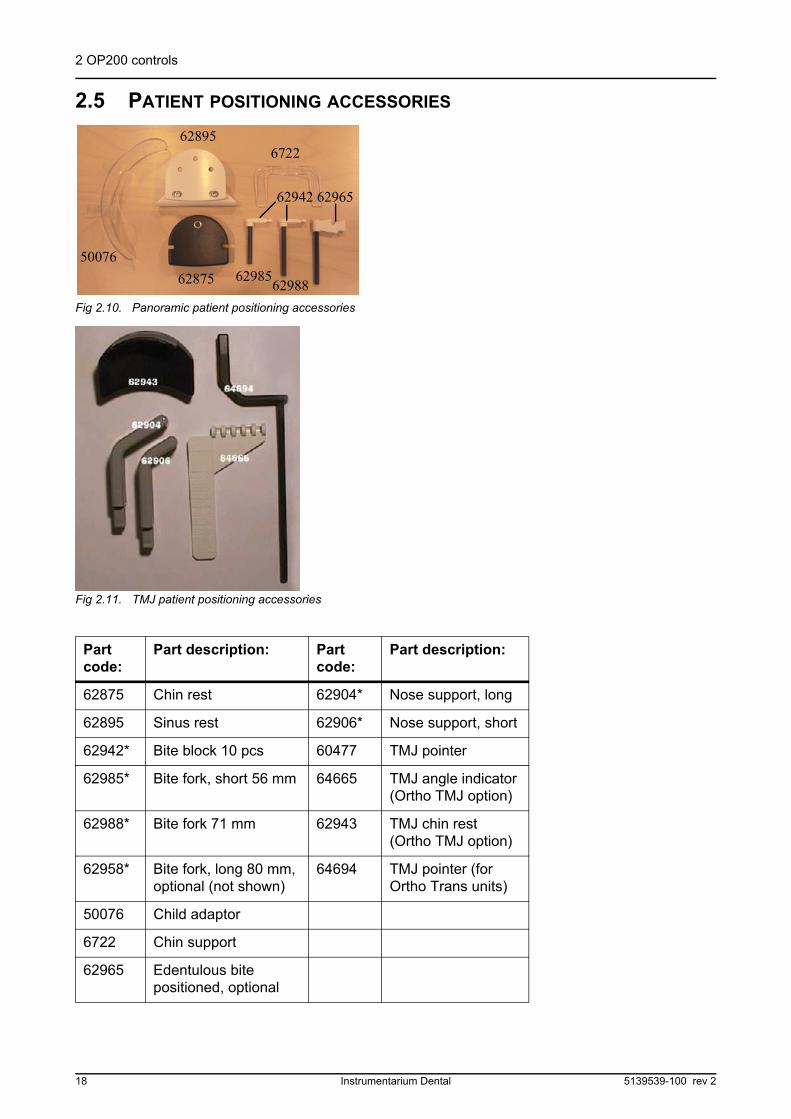
2.5 PATIENT POSITIONING ACCESSORIES
Fig 2.10. Panoramic patient positioning accessories
Fig 2.11. TMJ patient positioning accessories
Part code:
Part description: Part code:
Part description:
62875 Chin rest 62904* Nose support, long
62895 Sinus rest 62906* Nose support, short
62942* Bite block 10 pcs 60477 TMJ pointer
62985* Bite fork, short 56 mm 64665 TMJ angle indicator (Ortho TMJ option)
62988* Bite fork 71 mm 62943 TMJ chin rest (Ortho TMJ option)
62958* Bite fork, long 80 mm, optional (not shown)
64694 TMJ pointer (for Ortho Trans units)
50076 Child adaptor
6722 Chin support
62965 Edentulous bite positioned, optional
50076
62895
62875
6722
62942 62965
6298562988
18 Instrumentarium Dental 5139539-100 rev 2

2 OP200 controls
NOTE!
The parts marked with * are autoclavable.
Convenient bins for small accessories and disposables are located onthe both sides of the vertical carriage.
Fig 2.12. Left and right cabins.
2.6 OPTIONAL ACCESSORIES & DISPOSABLES
The following optional accessories, disposables and tools areavailable for the equipment:
Fig 2.13. Consumer accessories
Part code:
Part description:
6644 Bite fork coat, 200 pcs
7451 Chin rest coat, 200 pcs
89157453
6644
7451
7452
5139539-100 rev 2 Instrumentarium Dental 19

2 OP200 controls
2.7 CHANGING THE FUSES
Push inward on the fuse base and twist it counter-clockwise with ascrewdriwer. The fuse with the base will come out.
Remove the fuse from the base and replace it with the new one.Repeat this with each blown fuse.
Fasten both fuses by pushing the base in and twisting it clockwise witha screwdriver.
Use only appropriate fuses:
326 Littelfuse 10A (slow blow) 230 VAC line voltage
MDA-15 Cooper Bussman 15A (time delay) 115 VAC line voltage
7452 Temple support coat, 200 pcs
7453 Nose support coat, 200 pcs
8915 Ear holder coat, 20 pcs
Part code:
Part description:
20 Instrumentarium Dental 5139539-100 rev 2

3 Equipment preparations
3 Equipment preparations
3.1 CARE INSTRUCTIONS
X-ray devices are sophisticated electronic products includingadvanced technologies. As such, they have to be handled with a highdegree of care. This document gives the care instructions applicableto the Orthopantomograph® panoramic and cephalostat units.
NOTE!
It is strictly mandatory to follow these Care Instructions in order to notvoid the warranty of the product.
CAUTION!
As a standard recommendation, clean the unit regularly using non-agressive, mild, commercially available cleaning agents.
3.2 CLEANING RECOMMENDATIONS
The unit should be cleaned after every usage between the patients.Items and surfaces that are not given special instructions for cleaning,disinfecting and sterilizing, can be cleaned with soft cloth moisturedwith disinfective after every usage.
WARNING!
Always disconnect OP200 from mains or switch off the power prior tocleaning or disinfecting the unit.
CAUTION!
Do not allow water or other cleaning liquids to enter the unit interiorsince these may cause short-circuits or corrosion.
3.2.1 Cleaning
The purpose of cleaning and rinsing is to remove all adherent visiblesoil (eg. blood, protein substances and other debris), to reduce thenumber of particulate and micro-organisms, and to reduce the amountof pyrogenic and antigenic material.
Use a cloth moistened in cool-to-lukewarm, soapy water to clean theunit, and prevent coagulation and thus faciliate the removal of proteinsubstances. Then wipe with a cloth moistened in clear water. Milddetergent solution can be used. Use cleaners or solvents, which arelisted as allowed cleaning agents below. If you are uncertain of thenature of cleaning agent, do not use it.
5139539-100 rev 2 Instrumentarium Dental 21

3 Equipment preparations
Examples of cleaning agents that are allowed or prohibited whencleaning the unit panels:
Allowed: Methanol (metyl alcohol), Soap, Isopropyl alcohol, distilledwater.
Not allowed: Bentzene, Chlorine bentzene, Acetone, Acetic ether,agents containing phenol, paracetic acid, peroxide and other oxygen-cleaving agents, sodium hypochlorite and iodine-cleaving agents.
3.2.2 Disinfection and sterilization
The disinfection and sterilization concerns the parts of the equipmentlike bite block, chin support and accessories. Wipe manually withclean cloth moistured in disinfectant solution. Never use corrosive orsolvent disinfectants. All items and surfaces should be dried beforenext usage.
NOTE!
Wear gloves and other protective equipment during decontaminationprocess.
WARNING!
Do not use any disinfecting sprays since the vapor could ignitecausing injury.
Disinfecting techniques for both the unit and the room must complywith all laws and regulations that have jurisdiction of law within thejurisdiction on which the unit is.
3.2.2.1 Autoclave
Some removable parts in touch with the patient are sterilizable inautoclave. Such parts are:
Bite forks (62985, 62988, 62958), Bite block (62942) and Nosesupports (62906, 62904).
If autoclaving is performed for these items, disinfection by immersingin disinfectant solution for 10 minutes is not needed.
3.2.2.2 Steam sterilization
Recommended parameters for sterilizable parts are:
Gravity-displacement steam sterilization"Flash" sterilization:Temperature: 270 F (132°C)Exposure time: 3 minutes
Prevacuum steam sterilization"Flash" sterilization:
22 Instrumentarium Dental 5139539-100 rev 2
3 Equipment preparations
Temperature: 270 F (132°C)Exposure time: 3 minutes
Steam-flush pressure-pulse steam sterilizationTemperature: 270 F to 275 F (132°C to 135°C)Exposure time: 3 to 4 minutes
3.2.2.3 Ethylene oxide sterilization
Not recommended as sterilization process for OP200 parts.
3.2.3 Other sterilization processes
3.2.3.1 Dry heat sterilization
Dry heat sterilization can only be used with the bite forks.
Typical cycle parameters are:
Temperature: 338 F (170°C)
Exposure time: 60 minutes
Temperature: 375 F (190°C)
Exposure time: 6 minutes (unwrapped items) or 12 minutes (wrapped items) 3
3.2.3.2 Liquid chemical sterilant gases
Not recommended as sterilization process for OP200 parts.
3.2.3.3 Chemical sterilant gases
Not recommended as sterilization process for OP200 parts.
Testing
For example, a 2% hydrogen peroxide solution can be used to verifyremoval of protein from the unit. Soluton bubbles if it comes in contactwith blood or protein substances. If any bubbling is observed, thedecontamination process must be performed again.
5139539-100 rev 2 Instrumentarium Dental 23
3 Equipment preparations
3.3 LOADING THE PANORAMIC CASSETTE
For Panoramic, TMJ and QA imaging procedures, the initialequipment preparation is as follows:
NOTE!
Panoramic x-ray film is extremely sensitive to light. It is important thatthis film is loaded in a dark room having no light leaks. No amount ofwhite, blue, or green light is acceptable. If the darkroom is used, itmust also be organized to have a clean, dry work area under propersafelight illumination to load the cassette.
1 Place the cassette on the work surface. By releasing the lockinglevers (1) open the cassette fully. The cassette may look differentfrom the picture below, with two levers or hinges on top.
1 Locking levers2 Intensifying screens3 Film
2 Under safelight conditions, open the box of film. Holding the film(3) by the corners, place one piece into the cassette. Place itagainst the lower edge of the cassette. Do not slide the film overintensifying screens (2) as this will cause static electricity markson the film.
3 Close the cassette by pressing the cover and chassis firmlytogether until they lock, with some cassettes use lever to lock it.Be sure the film box top is closed before switching the lights on oropening the darkroom door.
4 To unload the cassette for processing, reverse the aboveprocedure.
5 Locate the power switch under the carriage backside. Turn thepower switch to the "I" position.
6 Orient the panoramic film cassette with the arrow pointing up, flatside towards x-ray tube and slide it into the cassette holder. Thegreen ready light will go on. Unit will rotate automatically forpatient positioning. Remove the ceph cassette. The unit worksonly with one cassette on it’s place.
1 1
2
3
24 Instrumentarium Dental 5139539-100 rev 2
3 Equipment preparations
NOTE!
The panoramic cassette will be on the correct position when it’s pin isin the socket of the cassette holder.
7 Lift the cassette holder up to make the patient positioning easier.Cassette holder may have been programmed to raiseautomatically when the cassette is inserted. If not press patientpositioning button. A built-in sensor prevents the exposurewithout the cassette in place. Move the head support as far aheadand up as possible.
Fig 3.3. Cassette holder movements
Fig 3.4. Moving the head support ahead
8 Select the panoramic collimation from the tube head. In OP200set the lever to the right, in other models select the panoramic
Fig 3.1. Ceph film cassette removal Fig 3.2. Panoramic film cassette orientation
down
up
5139539-100 rev 2 Instrumentarium Dental 25
3 Equipment preparations
collimator "PAN". One of the panoramic programs will be selectedautomatically on the control panel.
NOTE!
In cephalostat units checkthat the soft tissue filter is inposition 60.
9 Proceed to the sectionPanoramic proceduresfor Panoramic imaging and to the section Special imagingprocedures for TMJ and Sinus Maxillary imaging.
3.4 CEPHALOSTAT CASSETTE LOADING
For all cephalometric imaging procedures, the initial equipmentpreparation is as follows:
1 Load the cassette per section Loading the panoramic cassettesteps 1 to 3.
2 Locate the power switch under the carriage backside. Turn thepower switch to the "I" position.
3 Remove the panoramic cassette. The unit works only with onecassette on it’s place. There is no need to remove panoramicpositioning accessories.
4 Orient thecephalostat filmcassette with flatside towards x-raytube and install itinto the cassetteholder. Lift theretainer, if needed.
5 Cassette holder hasmarkings to placecassette for differentimaging procedures. Lower the cassette retainer. It will secure thecassette in place.
Fig 3.5. Panoramic film cassette Fig 3.6. Ceph film cassette orientation
tubeside
tub
esid
e
Asymmetric vertical view Asymmetric horizontal view
26 Instrumentarium Dental 5139539-100 rev 2
3 Equipment preparations
6 Select one of the cephalometric collimator positions from the tubehead. Technique factors and indicators change automatically tocephalometric values on the control panel.
7 Press the Start button on the control panel. The tube head andcassette rack will automatically position for cephalometricexposures. The green ready light will go on.
NOTE!
Ready light will only light when 1) the cephalostat collimation has been selected, 2) the cephalostat cassette is in place and 3) the cassette holder has been raised.
8 Go to the section 6 Making the Cephalometric Exposures.
Fig 3.7. Cephalostat collimator selection
Fig 3.8. Asymmetric vertical view, cephalostat on the right
Start button
Fig 3.9. Align the tube head for ceph exposure
Fig 3.10. The cassette holder up position
5139539-100 rev 2 Instrumentarium Dental 27
3 Equipment preparations
NOTE!
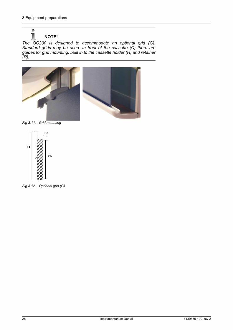
The OC200 is designed to accommodate an optional grid (G).Standard grids may be used. In front of the cassette (C) there areguides for grid mounting, built in to the cassette holder (H) and retainer(R).
Fig 3.11. Grid mounting
CG
R
H
Fig 3.12. Optional grid (G)
28 Instrumentarium Dental 5139539-100 rev 2
4 Panoramic procedures
4 Panoramic procedures
4.1 P1: STANDARD PANORAMIC EXPOSURE
1 Prepare the equipment per section Loading the panoramiccassette.
2 Verify that the light under program 1 (P1) in the control panel is lit.
3 Press patient positioning button to rotate the rotating unit to thepatient positioning position.
When the system is turned on it will automatically set itself to standardpanoramic with AEC (automatic exposure control) settings. No otherControl Panel settings are necessary.
NOTE!
If you wish to set the AEC density factors darker or lighter or wish toset the technique factors by patient size or manually, refer to sectionImaging Technique.
4 Install the chin rest and bite fork with bite fork rod (adult or child)with hygienic covers. Open temple supports.
.
5 Ask patient to remove any metal objects, such as eye glasses,jewelry, oral appliances, removable dentures, hearing aids, bibchain, etc., from the head and neck area. Shadows caused bythese opacities may obscure diagnosis.
6 It is strongly recommended to provide the patient with a leadapron for radiation protection.
7 Direct the patient to the unit and instruct to stand as straight andtall as possible. Ask patient to take a grip on handles.
Fig 4.1. P1: Image Layer Fig 4.2. P1 & AEC
Fig 4.3. Chin rest Fig 4.4. Open template supports
5139539-100 rev 2 Instrumentarium Dental 29

4 Panoramic procedures
By pressing the up or down button on the Patient positioning paneladjust the carriage height so the chin rest is at the patient's height.Have patient place chin on the chin rest.
8 Show the patient the grooves in the bite fork and place the bitefork into patient's mouth.
NOTE!
The patient can either be standing, seated, or in a wheelchair.
If the bite fork cannot be used because the malocclusion or missingteeth, remove the bite fork with rod (A), reset the chin support (B), anduse cotton rolls to separate the bite.
9 Positioning lights will switchon automatically when thecarriage is moved. Theystay on for 35 seconds oruntil exposure is initiated. Ifnecessary, lights can alsobe switched on and off atthe Positioning panel withlight button.
10 Ask the patient to take asmall step forward, to straighten the cervical vertebrae tominimize spinal shadow (See fig 4.8).
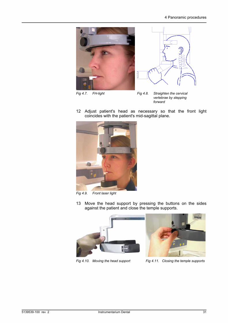
11 Patient's face and light lines can be seen in the curved mirror.Move the FH light to illuminate the patients' infra-orbital notch. Byslightly raising or lowering the carriage, position the patient sothat the Frankfort-Horizontal plane (FH) light passes over the earopening and the infra-orbital notch. Be sure the patient does notslump if carriage is lowered.
Fig 4.5. Standard patient positioning accessories installed
Fig 4.6. Hands on the grips and chin on the chin rest
B
A
30 Instrumentarium Dental 5139539-100 rev 2
4 Panoramic procedures
12 Adjust patient's head as necessary so that the front lightcoincides with the patient's mid-sagittal plane.
13 Move the head support by pressing the buttons on the sidesagainst the patient and close the temple supports.
Fig 4.7. FH-light Fig 4.8. Straighten the cervical vertebrae by stepping forward
Fig 4.9. Front laser light
Fig 4.10. Moving the head support Fig 4.11. Closing the temple supports
5139539-100 rev 2 Instrumentarium Dental 31
4 Panoramic procedures
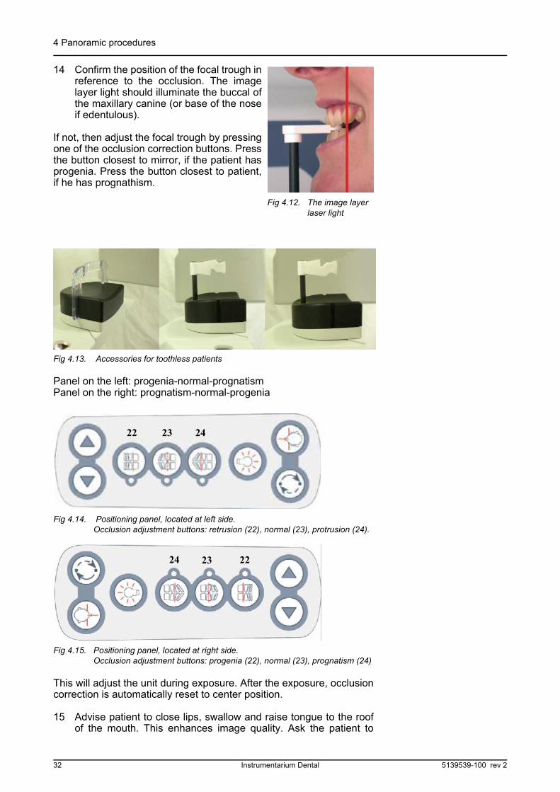
14 Confirm the position of the focal trough inreference to the occlusion. The imagelayer light should illuminate the buccal ofthe maxillary canine (or base of the noseif edentulous).
If not, then adjust the focal trough by pressingone of the occlusion correction buttons. Pressthe button closest to mirror, if the patient hasprogenia. Press the button closest to patient,if he has prognathism.
Fig 4.13. Accessories for toothless patients
Panel on the left: progenia-normal-prognatismPanel on the right: prognatism-normal-progenia
Fig 4.14. Positioning panel, located at left side. Occlusion adjustment buttons: retrusion (22), normal (23), protrusion (24).
Fig 4.15. Positioning panel, located at right side. Occlusion adjustment buttons: progenia (22), normal (23), prognatism (24)
This will adjust the unit during exposure. After the exposure, occlusioncorrection is automatically reset to center position.
15 Advise patient to close lips, swallow and raise tongue to the roofof the mouth. This enhances image quality. Ask the patient to
Fig 4.12. The image layer laser light
2322 24
24 23 22
32 Instrumentarium Dental 5139539-100 rev 2
4 Panoramic procedures
breathe through the nose and remain still during the exposure.Patient can be asked to close eyes.
16 After patient positioning press start button, and wait until the unitstops. Check that the patient positioning is not changed when therotating unit is moved to its starting position.
WARNING!
During the exposure cycle radiation control guidelines must beobserved.
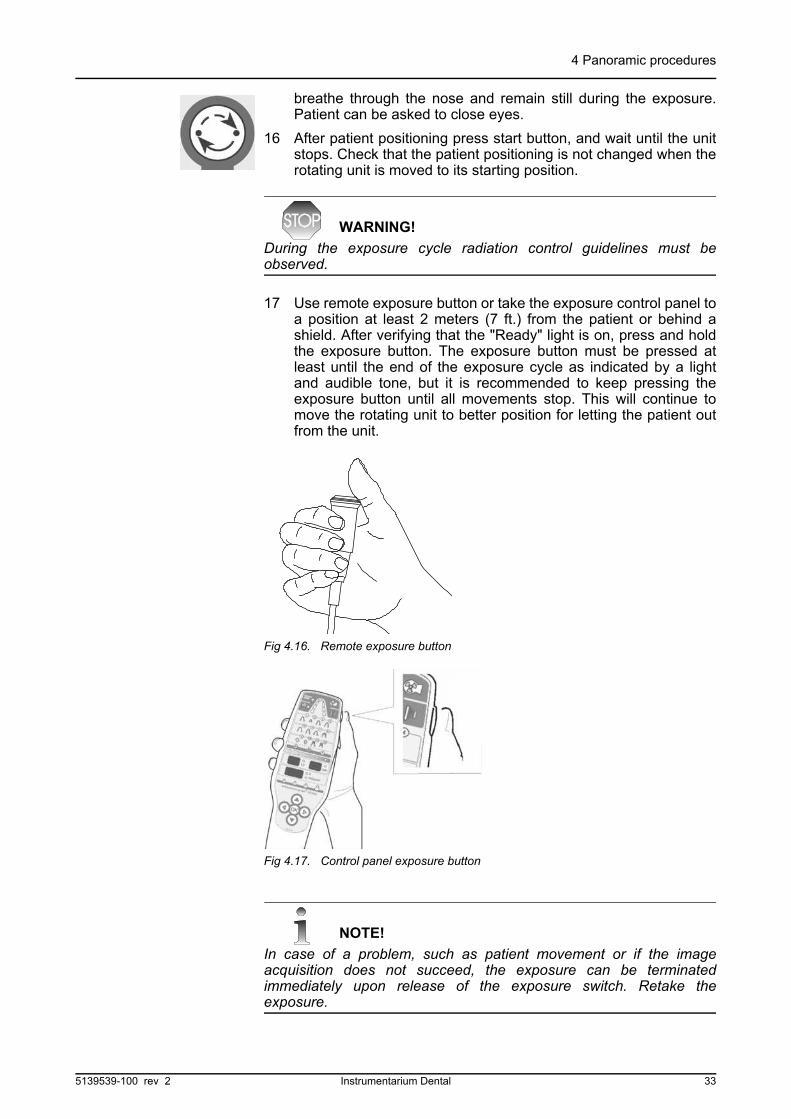
17 Use remote exposure button or take the exposure control panel toa position at least 2 meters (7 ft.) from the patient or behind ashield. After verifying that the "Ready" light is on, press and holdthe exposure button. The exposure button must be pressed atleast until the end of the exposure cycle as indicated by a lightand audible tone, but it is recommended to keep pressing theexposure button until all movements stop. This will continue tomove the rotating unit to better position for letting the patient outfrom the unit.
NOTE!
In case of a problem, such as patient movement or if the imageacquisition does not succeed, the exposure can be terminatedimmediately upon release of the exposure switch. Retake theexposure.
Fig 4.16. Remote exposure button
Fig 4.17. Control panel exposure button
5139539-100 rev 2 Instrumentarium Dental 33

4 Panoramic procedures
NOTE!
If exposure cannot be initiated and an error code appears on theexposure control panel, refer to section Failure Diagnostics forexplanation and correction.
18 At the end of the exposure, release temple supports and guidethe patient away from the unit.
19 Remove disposable covers and disinfect the unit.
NOTE!
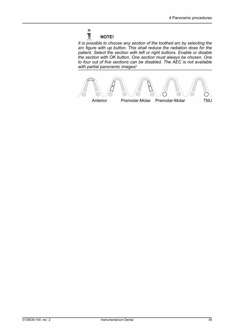
It is possible to choose any section of the toothed arc by selecting thearc figure with up button. This shall reduce the radiation dose for thepatient. Select the section with left or right buttons. Enable or disablethe section with OK button. One section must always be chosen. Oneto four out of five sections can be disabled. The AEC is not availablewith partial panoramic images!
4.2 P2: PEDIATRIC PANORAMIC EXPOSURE
Pediatric patients can be imaged with less radiation dosage andshorter exposure time. Patients with more narrow than average jawcan be exposed with this procedure, too.
1 Prepare the equipment per section Loading the panoramiccassette.
2 Select the pediatric exposure program on the Control Panel.Press the right button to move the flashing light from the standardpanoramic position to the pediatric position P2.
3 The system will remain in the Automatic Exposure Control mode.To set technique factors by patient size select one of the preprogrammed patient size icons or manually, refer to sectionImaging Technique for more information.
Anterior Premolar-Molar Premolar-Molar TMJ TMJ
Fig 4.18. P2: Image layer Fig 4.19. P2 & AEC mode
34 Instrumentarium Dental 5139539-100 rev 2
4 Panoramic procedures
Insert a child adapter to the head support when needed. Pressadapter ends towards each other with fingers, slide the adapteragainst the head support, and release. Pins will hold the adapter inplace.
.Fig 4.20. Child adapter
4 Position the patient and take exposure per steps 3 through 18 ofthe standard panoramic exposure procedure.
5 After the exposure return the system to the standard panoramicprogram by pressing the cursor buttons to move the flashing lightto the standard program position.
NOTE!
The system can be operated without radiation to demonstrate themovement to the child by setting the system to the Test mode.
To do this, press the down button to move the flashing light over theAEC mode (A).Then press the right button twice to move the light over the Test mode(T). Pressing the exposure switch will now cause the system to cyclewithout radiation. To return to operational status, press the left buttontwice to move the flashing light over the AEC mode (A).
NOTE!
The radiation dose can be reduced with small patients by using thecollimator for beam restriction. Choose the pediatric collimator byselecting first the panoramic collimator and then pulling the lever upfor one step.
NOTE!
It is possible to choose any section of the toothed arc by selecting thearc figure with up button. This shall reduce the radiation dose for thepatient. Select the section with left or right buttons. Enable or disablethe section with OK button. One section must always be chosen. Oneto four out of five sections can be disabled. The AEC is not availablewith partial panoramic images!
QA
Pediatric
PAN
5139539-100 rev 2 Instrumentarium Dental 35
4 Panoramic procedures
4.3 P3: ORTHO ZONE ENHANCED PANORAMIC EXPOSURE
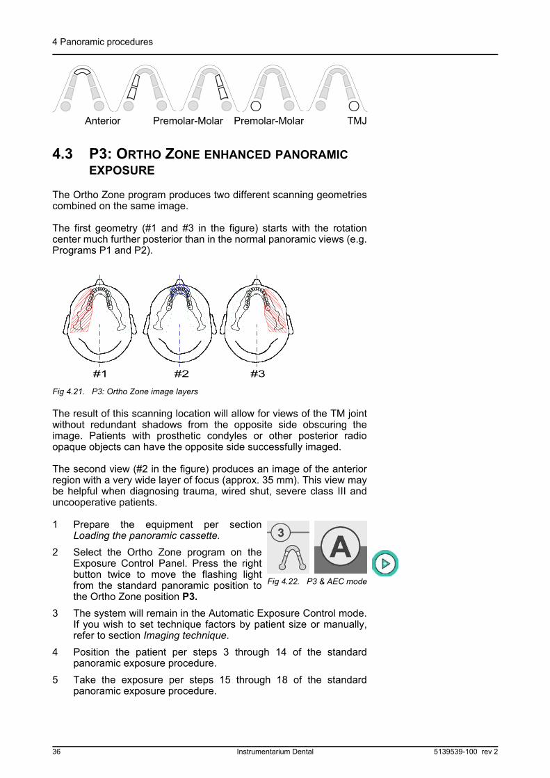
The Ortho Zone program produces two different scanning geometriescombined on the same image.
The first geometry (#1 and #3 in the figure) starts with the rotationcenter much further posterior than in the normal panoramic views (e.g.Programs P1 and P2).
Fig 4.21. P3: Ortho Zone image layers
The result of this scanning location will allow for views of the TM jointwithout redundant shadows from the opposite side obscuring theimage. Patients with prosthetic condyles or other posterior radioopaque objects can have the opposite side successfully imaged.
The second view (#2 in the figure) produces an image of the anteriorregion with a very wide layer of focus (approx. 35 mm). This view maybe helpful when diagnosing trauma, wired shut, severe class III anduncooperative patients.
1 Prepare the equipment per sectionLoading the panoramic cassette.
2 Select the Ortho Zone program on theExposure Control Panel. Press the rightbutton twice to move the flashing lightfrom the standard panoramic position tothe Ortho Zone position P3.
3 The system will remain in the Automatic Exposure Control mode.If you wish to set technique factors by patient size or manually,refer to section Imaging technique.
4 Position the patient per steps 3 through 14 of the standardpanoramic exposure procedure.
5 Take the exposure per steps 15 through 18 of the standardpanoramic exposure procedure.
Anterior Premolar-Molar Premolar-Molar TMJ
#1 #2 #3
Fig 4.22. P3 & AEC mode
36 Instrumentarium Dental 5139539-100 rev 2
4 Panoramic procedures
6 After the exposure return the system to the standard panoramicprogram by pressing the cursor buttons to move the flashing lightto the standard program position.
NOTE!
It is possible to choose any section of the toothed arc by selecting thearc figure with up button. This shall reduce the radiation dose for thepatient. Select the section with left or right buttons. Enable or disablethe section with OK button. One section must always be chosen. Oneto four out of five sections can be disabled. The AEC is not availablewith partial panoramic images!
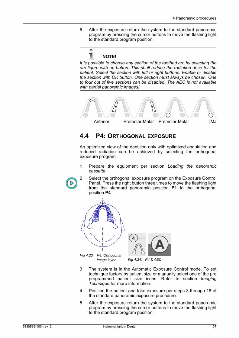
4.4 P4: ORTHOGONAL EXPOSURE
An optimized view of the dentition only with optimized anqulation andreduced radiation can be achieved by selecting the orthogonalexposure program.
1 Prepare the equipment per section Loading the panoramiccassette.
2 Select the orthogonal exposure program on the Exposure ControlPanel. Press the right button three times to move the flashing lightfrom the standard panoramic position P1 to the orthogonalposition P4.
3 The system is in the Automatic Exposure Control mode. To settechnique factors by patient size or manually select one of the preprogrammed patient size icons. Refer to section ImagingTechnique for more information.
4 Position the patient and take exposure per steps 3 through 18 ofthe standard panoramic exposure procedure.
5 After the exposure return the system to the standard panoramicprogram by pressing the cursor buttons to move the flashing lightto the standard program position.
Anterior Premolar-Molar Premolar-Molar TMJ
Fig 4.23. P4: Orthogonal image layer Fig 4.24. P4 & AEC
5139539-100 rev 2 Instrumentarium Dental 37

4 Panoramic procedures
NOTE!
It is possible to choose any section of the toothed arc by selecting thearc figure with up button. This shall reduce the radiation dose for thepatient. Select the section with left or right buttons. Enable or disablethe section with OK button. One section must always be chosen. Oneto four out of five sections can be disabled. The AEC is not availablewith partial panoramic images!
4.5 P5: WIDE ARCH PANORAMIC EXPOSURE
When the patient has a wider than normal dental arch, an improvedimage can be achieved by selecting the wide layer exposure program.
1 Prepare the equipment per section Loading the panoramiccassette.
2 Select the wide layer panoramic program on the ExposureControl Panel. Press the right button twice to move the flashinglight from the standard panoramic position P1 to the wide layerposition P3.
3 The system is in the Automatic Exposure Control mode. To settechnique factors by patient size select one of the preprogrammed patient size icons or manually, refer to sectionImaging Technique for more information.
4 Position the patient and take exposure per steps 3 through 18 ofthe standard panoramic exposure procedure.
5 After the exposure return the system to the standard panoramicprogram by pressing the cursor buttons to move the flashing lightto the standard program position.
Anterior Premolar Premolar Molar
Fig 4.25. P3: Image layer Fig 4.26. P3 & AEC mode
38 Instrumentarium Dental 5139539-100 rev 2
4 Panoramic procedures
NOTE!
It is possible to choose any section of the toothed arc by selecting thearc figure with up button. This shall reduce the radiation dose for thepatient. Select the section with left or right buttons. Enable or disablethe section with OK button. One section must always be chosen. Oneto four out of five sections can be disabled. The AEC is not availablewith partial panoramic images!
Anterior Premolar-Molar Premolar-Molar TMJ
5139539-100 rev 2 Instrumentarium Dental 39

4 Panoramic procedures
40 Instrumentarium Dental 5139539-100 rev 2
5 Special imaging procedures
5 Special imaging procedures
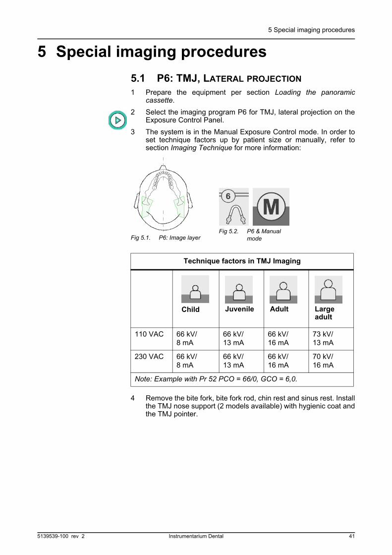
5.1 P6: TMJ, LATERAL PROJECTION
1 Prepare the equipment per section Loading the panoramiccassette.
2 Select the imaging program P6 for TMJ, lateral projection on theExposure Control Panel.
3 The system is in the Manual Exposure Control mode. In order toset technique factors up by patient size or manually, refer tosection Imaging Technique for more information:
4 Remove the bite fork, bite fork rod, chin rest and sinus rest. Installthe TMJ nose support (2 models available) with hygienic coat andthe TMJ pointer.
Technique factors in TMJ Imaging
110 VAC 66 kV/8 mA
66 kV/13 mA
66 kV/16 mA
73 kV/13 mA
230 VAC 66 kV/8 mA
66 kV/13 mA
66 kV/16 mA
70 kV/16 mA
Note: Example with Pr 52 PCO = 66/0, GCO = 6,0.
Fig 5.1. P6: Image layerFig 5.2. P6 & Manual
mode
Child Juvenile Adult Largeadult
5139539-100 rev 2 Instrumentarium Dental 41

5 Special imaging procedures
5 Ask patient to remove any metal objects, such as eye glasses,jewelry, oral appliances, removable dentures, hearing aids, bibchain, etc., from the head and neck area. Shadows caused bythese opacities may obscure diagnosis.
6 It is strongly recommended to provide the patient with a leadapron for radiation protection.
7 Direct the patient to the machine and instruct to stand as straightand tall as possible. Ask patient to take a grip on handles.
By pressing the up or down button on the Positioning Control paneladjust the carriage height so the TMJ nose support is at the patient'sheight. Have patient place nose against TMJ nose support.
8 Adjust patient's head as necessary so that the front lightcoincides with the patient's mid-sagittal plane. Move the headsupport by pressing it from sides against the patient and close thetemple supports.
Fig 5.3. TMJ pointer Fig 5.4. TMJ pointer in correct position
Fig 5.5. TMJ nose support, long and short
42 Instrumentarium Dental 5139539-100 rev 2
5 Special imaging procedures
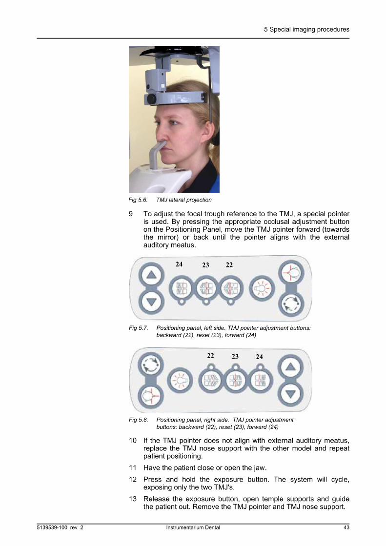
9 To adjust the focal trough reference to the TMJ, a special pointeris used. By pressing the appropriate occlusal adjustment buttonon the Positioning Panel, move the TMJ pointer forward (towardsthe mirror) or back until the pointer aligns with the externalauditory meatus.
10 If the TMJ pointer does not align with external auditory meatus,replace the TMJ nose support with the other model and repeatpatient positioning.
11 Have the patient close or open the jaw.
12 Press and hold the exposure button. The system will cycle,exposing only the two TMJ's.
13 Release the exposure button, open temple supports and guidethe patient out. Remove the TMJ pointer and TMJ nose support.
Fig 5.6. TMJ lateral projection
24 23 22
Fig 5.7. Positioning panel, left side. TMJ pointer adjustment buttons: backward (22), reset (23), forward (24)
22 23 24
Fig 5.8. Positioning panel, right side. TMJ pointer adjustment buttons: backward (22), reset (23), forward (24)
5139539-100 rev 2 Instrumentarium Dental 43
5 Special imaging procedures
14 If the Ortho ID is available, mark the film with the patient's name,Id number, correction angles and notes. Process the film.
15 After the exposure return the system to the standard panoramicprogram by pressing the cursor buttons to move the flashing lightto the standard program position.
NOTE!
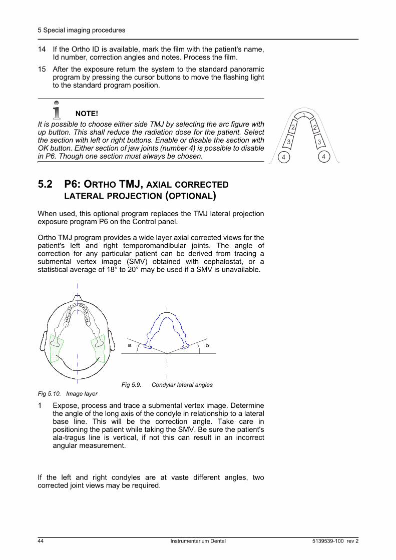
It is possible to choose either side TMJ by selecting the arc figure withup button. This shall reduce the radiation dose for the patient. Selectthe section with left or right buttons. Enable or disable the section withOK button. Either section of jaw joints (number 4) is possible to disablein P6. Though one section must always be chosen.
5.2 P6: ORTHO TMJ, AXIAL CORRECTED LATERAL PROJECTION (OPTIONAL)
When used, this optional program replaces the TMJ lateral projectionexposure program P6 on the Control panel.
Ortho TMJ program provides a wide layer axial corrected views for thepatient's left and right temporomandibular joints. The angle ofcorrection for any particular patient can be derived from tracing asubmental vertex image (SMV) obtained with cephalostat, or astatistical average of 18° to 20° may be used if a SMV is unavailable.
Fig 5.10. Image layer
1 Expose, process and trace a submental vertex image. Determinethe angle of the long axis of the condyle in relationship to a lateralbase line. This will be the correction angle. Take care inpositioning the patient while taking the SMV. Be sure the patient'sala-tragus line is vertical, if not this can result in an incorrectangular measurement.
If the left and right condyles are at vaste different angles, twocorrected joint views may be required.
a b
Fig 5.9. Condylar lateral angles
44 Instrumentarium Dental 5139539-100 rev 2
5 Special imaging procedures
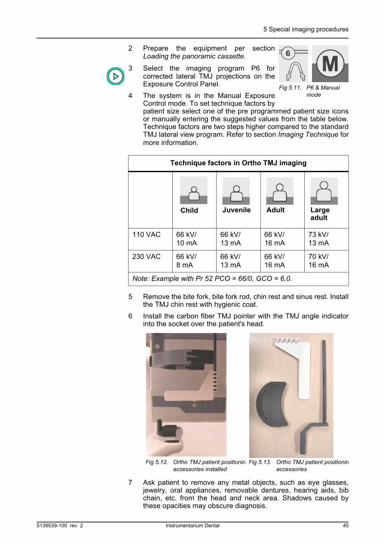
2 Prepare the equipment per sectionLoading the panoramic cassette.
3 Select the imaging program P6 forcorrected lateral TMJ projections on theExposure Control Panel.
4 The system is in the Manual ExposureControl mode. To set technique factors bypatient size select one of the pre programmed patient size iconsor manually entering the suggested values from the table below.Technique factors are two steps higher compared to the standardTMJ lateral view program. Refer to section Imaging Technique formore information.
5 Remove the bite fork, bite fork rod, chin rest and sinus rest. Installthe TMJ chin rest with hygienic coat.
6 Install the carbon fiber TMJ pointer with the TMJ angle indicatorinto the socket over the patient's head.
7 Ask patient to remove any metal objects, such as eye glasses,jewelry, oral appliances, removable dentures, hearing aids, bibchain, etc. from the head and neck area. Shadows caused bythese opacities may obscure diagnosis.
Technique factors in Ortho TMJ imaging
110 VAC 66 kV/10 mA
66 kV/13 mA
66 kV/16 mA
73 kV/13 mA
230 VAC 66 kV/8 mA
66 kV/13 mA
66 kV/16 mA
70 kV/16 mA
Note: Example with Pr 52 PCO = 66/0, GCO = 6,0.
Fig 5.11. P6 & Manual mode
Child Juvenile Adult Largeadult
Fig 5.12. Ortho TMJ patient positioninaccessories installed
Fig 5.13. Ortho TMJ patient positioninaccessories
5139539-100 rev 2 Instrumentarium Dental 45

5 Special imaging procedures
8 It is strongly recommended to provide the patient with a leadapron for radiation protection.
9 Direct the patient to the machine and instruct to stand as straightand tall as possible. Ask patient to take a grip on handles. Bypressing the up or down button on the Positioning Control paneladjust the carriage height so that the TMJ chin rest is at thepatient's chin level. Have patient place chin against the TMJ chinrest.
10 Adjust patient's head as necessary so that the front lightcoincides with the patient's mid-sagittal plane. Move the headsupport by pressing it from sides against the patient and close thetemple supports.
11 To adjust the x-ray beam angle to the patient's condylar angle theTMJ pointer and angle indicator are used. By pressing theappropriate occlusal button on the Patient positioning panel,move the TMJ angle indicator forward or back until the desiredangle is displayed over the patient's condyle.
Fig 5.14. Ortho TMJ, patient positioning Fig 5.15. Angle indicator adjustment
24 23 22
Fig 5.16. Positioning panel, left side. TMJ pointer adjustment buttons: backward (22), reset (23), forward (24)
46 Instrumentarium Dental 5139539-100 rev 2
5 Special imaging procedures
12 Have the patient gently close the jaws together.
13 Press and hold the exposure button. The system will cycleexposing only the two TMJ's.
14 Release the exposure button, open temple supports and guidethe patient out. Remove the TMJ pointer, TMJ chin rest and TMJangle indicator.
15 If the Ortho ID is available, mark the film with the patient's name, Id number, correction angles and notes. Process the film.
16 After the exposure return the system to the standard panoramicprogram by pressing the cursor buttons to move the flashing lightto the standard program position. Remove Ortho TMJaccessories.
NOTE!
It is possible to choose either side TMJ by selecting the arc figure withup button. This shall reduce the radiation dose for the patient. Selectthe section with left or right buttons. Enable or disable the section withOK button. Either section of jaw joints (number 4) is possible to disablein P6. Though one section must always be chosen.
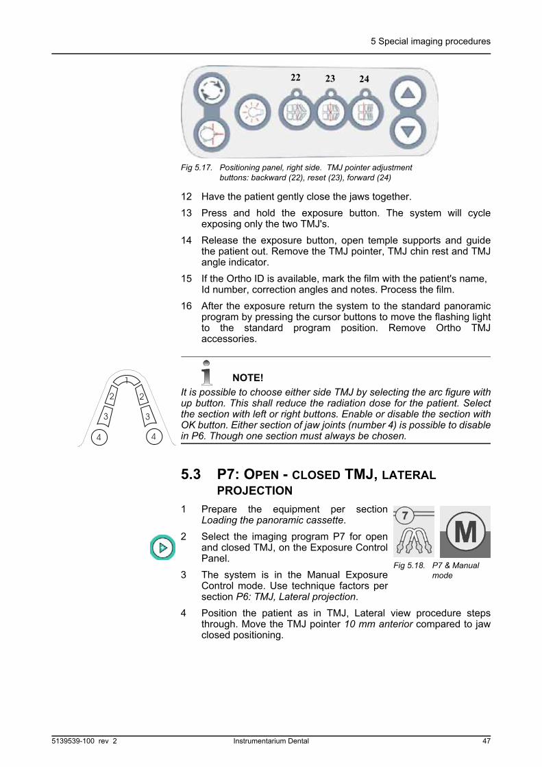
5.3 P7: OPEN - CLOSED TMJ, LATERAL PROJECTION
1 Prepare the equipment per sectionLoading the panoramic cassette.
2 Select the imaging program P7 for openand closed TMJ, on the Exposure ControlPanel.
3 The system is in the Manual ExposureControl mode. Use technique factors persection P6: TMJ, Lateral projection.
4 Position the patient as in TMJ, Lateral view procedure stepsthrough. Move the TMJ pointer 10 mm anterior compared to jawclosed positioning.
22 23 24
Fig 5.17. Positioning panel, right side. TMJ pointer adjustment buttons: backward (22), reset (23), forward (24)
Fig 5.18. P7 & Manual mode
5139539-100 rev 2 Instrumentarium Dental 47

5 Special imaging procedures
5
6 First Exposure: Have the patient close jaw. Press and keep downthe exposure button. The system will cycle, exposing first the twoTMJ's and will stop prepared for next view.
7 Release the exposure button. "Ready" light will be on again.
NOTE!
Do not remove the cassette nor make any selections on Control panel.
8 Second Exposure: Have the patient open the jaw. Press andkeep down the exposure button. The system will cycle exposingthe open TMJ's in the center of the same film.
9 Release the exposure button, open temple supports and guidethe patient out. Remove the TMJ pointer and TMJ nose support.
10 If the Ortho ID is available, mark the film with the patient's name, Id number, correction angles and notes. Process the film.
11 Return the system to the standard panoramic program.
NOTE!
It is possible to choose either side TMJ by selecting the arc figure withup button. This shall reduce the radiation dose for the patient. Selectthe section with left or right buttons. Enable or disable the section withOK button. Either section of jaw joints (number 4) is possible to disablein P7. Though one section must always be chosen.
Fig 5.19. TMJ PA Projection
48 Instrumentarium Dental 5139539-100 rev 2

5 Special imaging procedures
5.4 P8: TMJ, POSTEROANTERIOR PROJECTION
1 Prepare the equipment per section Loading the panoramiccassette.
2 Select the imaging program P8 for TMJ, PA projection on theExposure Control Panel.
3 The system is in the Manual Exposure Control mode. Usetechnique factors per section P6: TMJ, Lateral projection.
4 Position the patient as in TMJ, Lateral view and procedure steps4 through 10. Move the TMJ pointer 10 mm anterior compared tojaw closed positioning.
Fig 5.22. TMJ PA projection
5 Have the patient open the jaw.
6 Press and hold the exposure button. The system will cycle andexpose only as necessary to display the TMJ's in PA projection.
7 Release the exposure button, open temple supports and guidethe patient out. Remove the TMJ pointer and TMJ support.
8 If the Ortho ID is available, mark the film with the patient's name,Id number, correction angles and notes. Process the film.
9 Return the system to the standard panoramic program.
Fig 5.20. P8: Image layer
Fig 5.21. P8 & Manual mode
5139539-100 rev 2 Instrumentarium Dental 49
5 Special imaging procedures
NOTE!
It is possible to choose either side TMJ by selecting the arc figure withup button. This shall reduce the radiation dose for the patient. Selectthe section with left or right buttons. Enable or disable the section withOK button. Either section of jaw joints (number 4) is possible to disablein P7. Though one section must always be chosen.
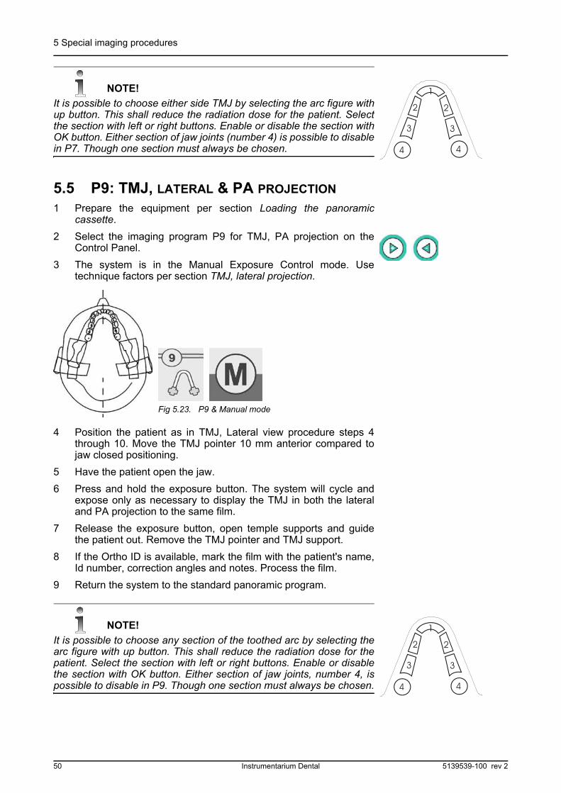
5.5 P9: TMJ, LATERAL & PA PROJECTION
1 Prepare the equipment per section Loading the panoramiccassette.
2 Select the imaging program P9 for TMJ, PA projection on theControl Panel.
3 The system is in the Manual Exposure Control mode. Usetechnique factors per section TMJ, lateral projection.
4 Position the patient as in TMJ, Lateral view procedure steps 4through 10. Move the TMJ pointer 10 mm anterior compared tojaw closed positioning.
5 Have the patient open the jaw.
6 Press and hold the exposure button. The system will cycle andexpose only as necessary to display the TMJ in both the lateraland PA projection to the same film.
7 Release the exposure button, open temple supports and guidethe patient out. Remove the TMJ pointer and TMJ support.
8 If the Ortho ID is available, mark the film with the patient's name,Id number, correction angles and notes. Process the film.
9 Return the system to the standard panoramic program.
NOTE!
It is possible to choose any section of the toothed arc by selecting thearc figure with up button. This shall reduce the radiation dose for thepatient. Select the section with left or right buttons. Enable or disablethe section with OK button. Either section of jaw joints, number 4, ispossible to disable in P9. Though one section must always be chosen.
Fig 5.23. P9 & Manual mode
50 Instrumentarium Dental 5139539-100 rev 2

5 Special imaging procedures
5.6 P10: MAXILLARY SINUS VIEW
1 Prepare the equipment per sectionLoading the panoramic cassette.
2 Select the imaging program P10 for amaxillary sinus view on the ExposureControl Panel.
3 The system is in the Manual ExposureControl mode. Use one step higher technique factors comparedto TMJ imaging:
4 Remove the bite fork, bite fork rod and chin rest. Install the bitefork rod over the sinus rest. Install hygienic covers.
5 Direct the patient to the machine and instruct to stand as straightand tall as possible. Ask patient to take a grip on handles.
By pressing the up or down button on the Positioning Control paneladjust the carriage height so that the sinus rest is at the patient's noseheight. Have patient place nose against sinus rest.
Technique factors Maxillary Sinus Imaging
110 VAC 66 kV/8 mA
66 kV/13 mA
70 kV/12 mA
73 kV/12 mA
230 VAC 66 kV/8 mA
66 kV/13 mA
66 kV/16 mA
70 kV/16 mA
Note: Example with Pr 52 PCO = 66/0, GCO = 6,0.
Fig 5.24. P10 & Manual
Child Juvenile Adult Largeadult
5139539-100 rev 2 Instrumentarium Dental 51
5 Special imaging procedures
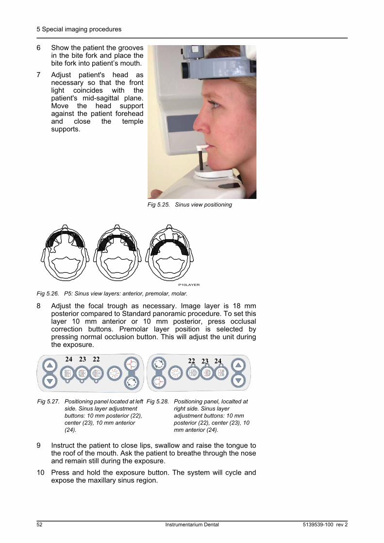
6 Show the patient the groovesin the bite fork and place thebite fork into patient’s mouth.
7 Adjust patient's head asnecessary so that the frontlight coincides with thepatient's mid-sagittal plane.Move the head supportagainst the patient foreheadand close the templesupports.
8 Adjust the focal trough as necessary. Image layer is 18 mmposterior compared to Standard panoramic procedure. To set thislayer 10 mm anterior or 10 mm posterior, press occlusalcorrection buttons. Premolar layer position is selected bypressing normal occlusion button. This will adjust the unit duringthe exposure.
9 Instruct the patient to close lips, swallow and raise the tongue tothe roof of the mouth. Ask the patient to breathe through the noseand remain still during the exposure.
10 Press and hold the exposure button. The system will cycle andexpose the maxillary sinus region.
Fig 5.25. Sinus view positioning
P10LAYER
Fig 5.26. P5: Sinus view layers: anterior, premolar, molar.
222324
Fig 5.27. Positioning panel located at left side. Sinus layer adjustment buttons: 10 mm posterior (22), center (23), 10 mm anterior (24).
Fig 5.28. Positioning panel, localted at right side. Sinus layer adjustment buttons: 10 mm posterior (22), center (23), 10 mm anterior (24).
22 23 24
52 Instrumentarium Dental 5139539-100 rev 2

5 Special imaging procedures
11 Release the exposure button, open temple supports and guidethe patient out. Remove the bite fork and rod, reset chin rest andbite fork.
12 If the Ortho ID is available, mark the film with the patient's name,Id number, correction angles and notes. Process the film.
13 Return the system to the standard panoramic program.
NOTE!
It is not possible to choose any section of the toothed arc of the arcfigure in the control panel in P10.
5139539-100 rev 2 Instrumentarium Dental 53

5 Special imaging procedures
54 Instrumentarium Dental 5139539-100 rev 2
6 Cephalometric procedures (optional)
6 Cephalometric procedures (optional)Program P11 and P12 are a cephalometric imaging programs usingManual Exposure Control. Image magnification can be adjusted,ranging from 8% to 14%. Positioning steps demonstrated are for left-mounted cephalostat, steps for right-mounted cephalostat are similar.
6.1 P11: CEPHALO LATERAL PROJECTION
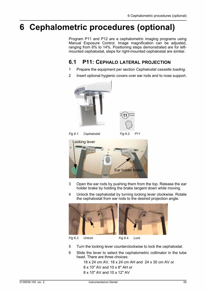
1 Prepare the equipment per section Cephalostat cassette loading.
2 Insert optional hygienic covers over ear rods and to nose support.
3 Open the ear rods by pushing them from the top. Release the earholder brake by holding the brake tangent down while moving.
4 Unlock the cephalostat by turning locking lever clockwise. Rotatethe cephalostat from ear rods to the desired projection angle.
5 Turn the locking lever counterclockwise to lock the cephalostat.
6 Slide the lever to select the cephalometric collimator in the tubehead. There are three choices:
18 x 24 cm AV, 18 x 24 cm AH and 24 x 30 cm AV or8 x 10" AV and 10 x 8" AH or8 x 10" AV and 10 x 12" AV
Fig 6.1. Cephalostat Fig 6.2. P11
Ear holder brake
Locking lever
Fig 6.3. Unlock Fig 6.4. Lock
5139539-100 rev 2 Instrumentarium Dental 55

6 Cephalometric procedures (optional)
7 Verify that the cassette position is the same as the collimation.
8 Unit will be in the cephalometric mode, P11. This is indicatedwhen indicator P11 is lit.
9 Adjust the unit height. Positioning lights are off.
10 Place the patient in standing or seated position under thecephalostat. Adjust the cephalostat to proper height andintroduce the ear rods to external auditory meatuses.
11 Tilt the nasion support down and set it to nasion. See thatpatient's head is correctly inclined. Adjust the nose supportvertically and horizontally by hand.
12 The image magnification is8% - 14%. Nose supporthas a scale with 1 mm tickmarks. This scale will beseen on the film. Choosethe desired magnificationby moving the cassetteholder.
13 Read the correct soft-tissue filtering value fromthe scale, under thecephalostat. Set the samevalue to the collimator. Toincrease filtering set the lever to a lower value. To decreasefiltering set the lever to a higher value.
Fig 6.5. Cassette holder movement
Fig 6.6. Soft tissue filter scale Fig 6.7. Lever for soft tissue filtering
56 Instrumentarium Dental 5139539-100 rev 2
6 Cephalometric procedures (optional)
NOTE!
60 mm added to the display reading gives the actual distance from earrods to nasion.
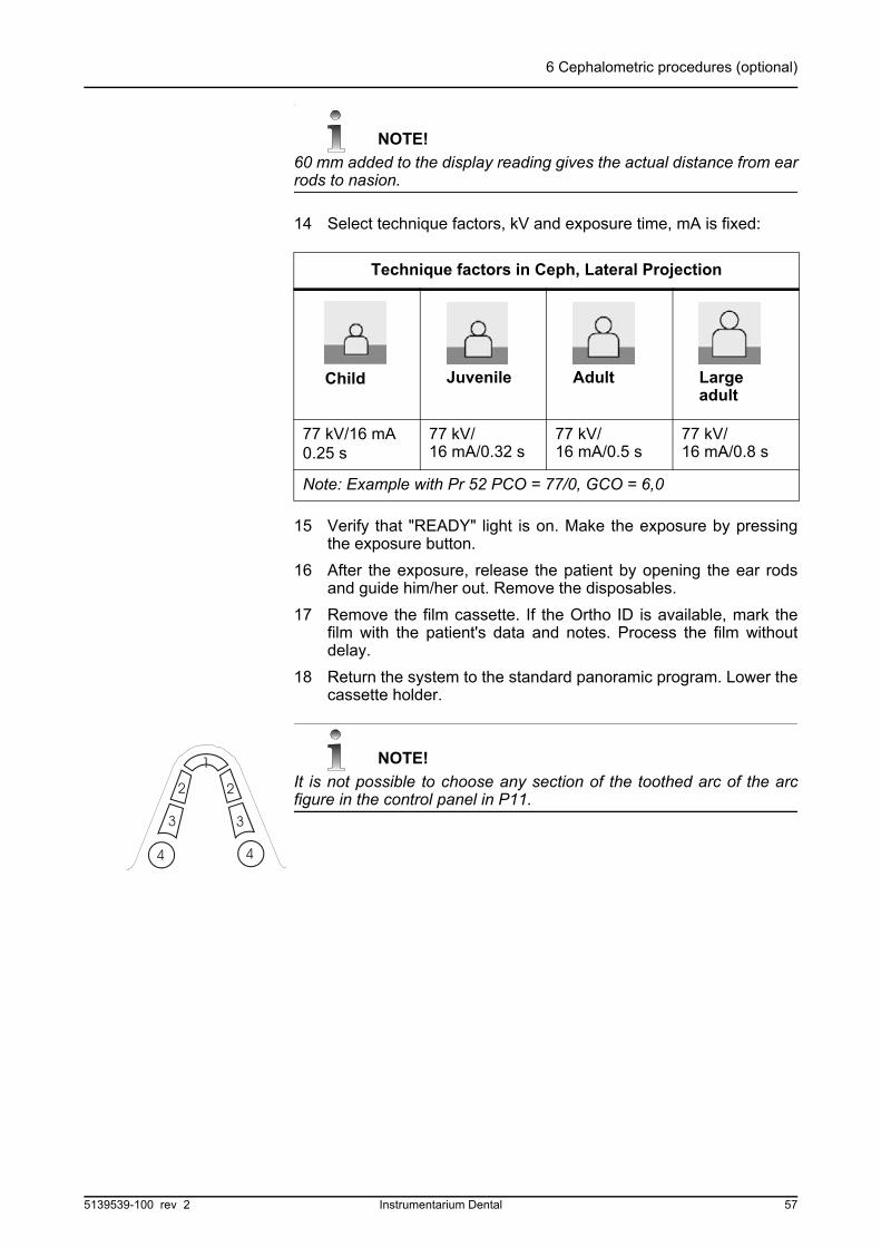
14 Select technique factors, kV and exposure time, mA is fixed:
15 Verify that "READY" light is on. Make the exposure by pressingthe exposure button.
16 After the exposure, release the patient by opening the ear rodsand guide him/her out. Remove the disposables.
17 Remove the film cassette. If the Ortho ID is available, mark thefilm with the patient's data and notes. Process the film withoutdelay.
18 Return the system to the standard panoramic program. Lower thecassette holder.
NOTE!
It is not possible to choose any section of the toothed arc of the arcfigure in the control panel in P11.
Technique factors in Ceph, Lateral Projection
77 kV/16 mA 0.25 s
77 kV/16 mA/0.32 s
77 kV/16 mA/0.5 s
77 kV/16 mA/0.8 s
Note: Example with Pr 52 PCO = 77/0, GCO = 6,0
Child Juvenile Adult Largeadult
5139539-100 rev 2 Instrumentarium Dental 57

6 Cephalometric procedures (optional)
6.2 P12: CEPHALO POSTERIOR-ANTERIOR (PA) PROJECTION
This procedure can be used for PA and AP views.
1 Prepare the equipment per section Cephalostatcassette loading.
2 Insert hygienic covers to ear rods and to nosesupport. Tilt the nose support away from theradiation field. Open the ear rods holders by pushingthem from the top. Release the ear holder brake by holding thebrake tangent down while moving.
3 Unlock the cephalostat by turning the locking lever clockwise.Rotate the cephalostat from ear rods for symmetrical view. Turnthe locking lever counter clockwise to lock the cephalostat.
4 Slide the lever to 18 x 24 SV (or 8 x 10" SV) to select thecollimator for a symmetrical view, PA or facial projection. Movethe soft tissue wedge out of the x-ray beam by sliding the softtissue lever to the value of 60.
5 Position the patient in standing or seated position under thecephalostat.
6 Adjust the cephalostat to proper height and introduce the ear rodsto external auditory meatuses. See that patient's head is inclined.
7 Set the cephalostat cassette holder as close to the patient aspossible. The distance reading, indicating magnification, can bewritten down for future references.
Fig 6.8. P12
Ear holder brake
Locking lever
Fig 6.9. Symmetrical view, collimator selection
Fig 6.10. Patient positioning for PA view
58 Instrumentarium Dental 5139539-100 rev 2

6 Cephalometric procedures (optional)
8 Select technique factors, kV and exposure time. PA / facial viewshave one step higher technique factors compared to the lateralprojection:
9 Make the exposure by pressing the exposure button. After theexposure, release the patient by opening the ear rods and guidehim out. Remove the disposables.
10 Remove the film cassette. If the Ortho ID is available, mark thefilm with the patient's data and notes. Process the film withoutdelay.
11 Return the system to the standard panoramic program.
NOTE!
It is not possible to choose any section of the toothed arc of the arcfigure in the control panel in P12.
6.3 P7: AXIAL VIEW OF THE MANDIBLE EXPOSURE
Prepare the equipment per section Cephalostat Cassette Loading. Insert hygienic covers to ear rods. Tilt the nasion support away from the radiation field. Open the ear rods holders by pushing them from top. Release the ear holder brake by holding the brake tangent down while moving.
Technique factors in Ceph, PA/AP Projection
77 kV/16 mA/ 0.4 s
77 kV/16 mA/ 0.5 s
77 kV/16 mA/ 0.8 s
77 kV/16 mA/1.25 s
Note: Example with Pr 52 PCO = 77/0, GCO = 6,0
Child Juvenile Adult Largeadult
Fig 6.11. Reverse Townes view
5139539-100 rev 2 Instrumentarium Dental 59

6 Cephalometric procedures (optional)
12 Unlock the cephalostat by turning locking lever clockwise. Rotatethe cephalostat from ear rods for the symmetrical view. Turn thelocking lever counter clockwise to lock the cephalostat.
13 Slide the lever to 18 x 24 SV (or 8 x 10" SV) to select thecollimator for symmetric view. Move the soft tissue lever to valueof 60.
14 Position the patient seated under the cephalostat in AP-projection.
15 Gently position the ear holders into the external auditorymeatuses.
16 Ask the patient to incline the head strongly backwards, as muchas possible. Frankfurt horizontal plane is positioned parallel to thecassette, i.e. occlusal plane is perpendicular to the floor.
17 Set the cephalostat cassette holder as close to the patient aspossible. The distance reading, indicating magnification, can bewritten down for future references.
18 Select technique factors and make the exposure per section P5: PA Projection, steps 7 to 10.
6.4 P5: REWERSE TOWNE PROJECTION EXPOSURE
1 Prepare the equipment per section Cephalostat cassette loading.Insert hygienic covers to ear rods. Tilt the nasion support awayfrom the radiation field. Open the ear rod holders by pushing themfrom top. Release the ear holder brake by holding the braketangent down while moving.
Ear holder brake
Locking lever
Fig 6.12. Reverse Townes view Fig 6.13. Reverse Townes view
60 Instrumentarium Dental 5139539-100 rev 2
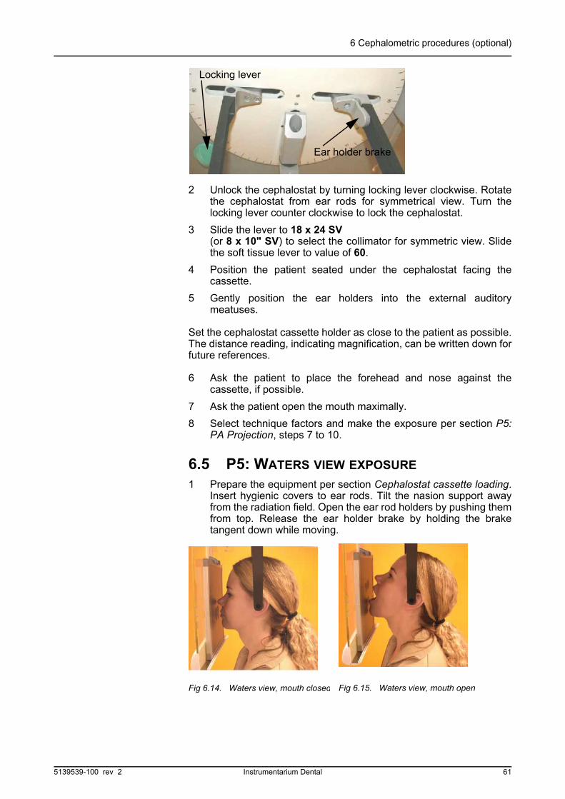
6 Cephalometric procedures (optional)
2 Unlock the cephalostat by turning locking lever clockwise. Rotatethe cephalostat from ear rods for symmetrical view. Turn thelocking lever counter clockwise to lock the cephalostat.
3 Slide the lever to 18 x 24 SV (or 8 x 10" SV) to select the collimator for symmetric view. Slidethe soft tissue lever to value of 60.
4 Position the patient seated under the cephalostat facing thecassette.
5 Gently position the ear holders into the external auditorymeatuses.
Set the cephalostat cassette holder as close to the patient as possible.The distance reading, indicating magnification, can be written down forfuture references.
6 Ask the patient to place the forehead and nose against thecassette, if possible.
7 Ask the patient open the mouth maximally.
8 Select technique factors and make the exposure per section P5:PA Projection, steps 7 to 10.
6.5 P5: WATERS VIEW EXPOSURE
1 Prepare the equipment per section Cephalostat cassette loading.Insert hygienic covers to ear rods. Tilt the nasion support awayfrom the radiation field. Open the ear rod holders by pushing themfrom top. Release the ear holder brake by holding the braketangent down while moving.
Ear holder brake
Locking lever
Fig 6.14. Waters view, mouth closed Fig 6.15. Waters view, mouth open
5139539-100 rev 2 Instrumentarium Dental 61

6 Cephalometric procedures (optional)
2 Unlock the cephalostat by turning locking lever clockwise. Rotatethe cephalostat from ear rods for symmetrical view. Turn thelocking lever counter clockwise to lock the cephalostat.
3 Slide the lever to 18 x 24 SV (or 8 x 10 "SV) to select the collimator for symmetric view. Slidethe soft tissue lever to value of 60.
4 Position the patient seated under the cephalostat facing thecassette.
5 Gently position the ear holders into the external auditorymeatuses.
Set the cephalostat cassette holder as close to the patient as possible.The distance reading, indicating magnification, can be written down forfuture references.
6 Ask the patient open the mouth and place the nose and chinagainst the cassette, if possible.
7 Select technique factors and make the exposure per section P5:PA Projection, steps 7 to 10.
6.6 P7: CARPUS VIEW EXPOSURE (OPTIONAL)
This procedure can be used for Carpus view.
1 Prepare the equipment per section Cephalostat cassette loading.Tilt the nose support away from the radiation field. Open the earrods holders by pushing them from top.
2 Unlock the cephalostat by turning locking lever clockwise. Rotatethe cephalostat from ear rods for symmetrical view. Turn thelocking lever counter clockwise to lock the cephalostat.
Fig 6.16. Waters view, degrees
Ear holder brake
Locking lever
62 Instrumentarium Dental 5139539-100 rev 2
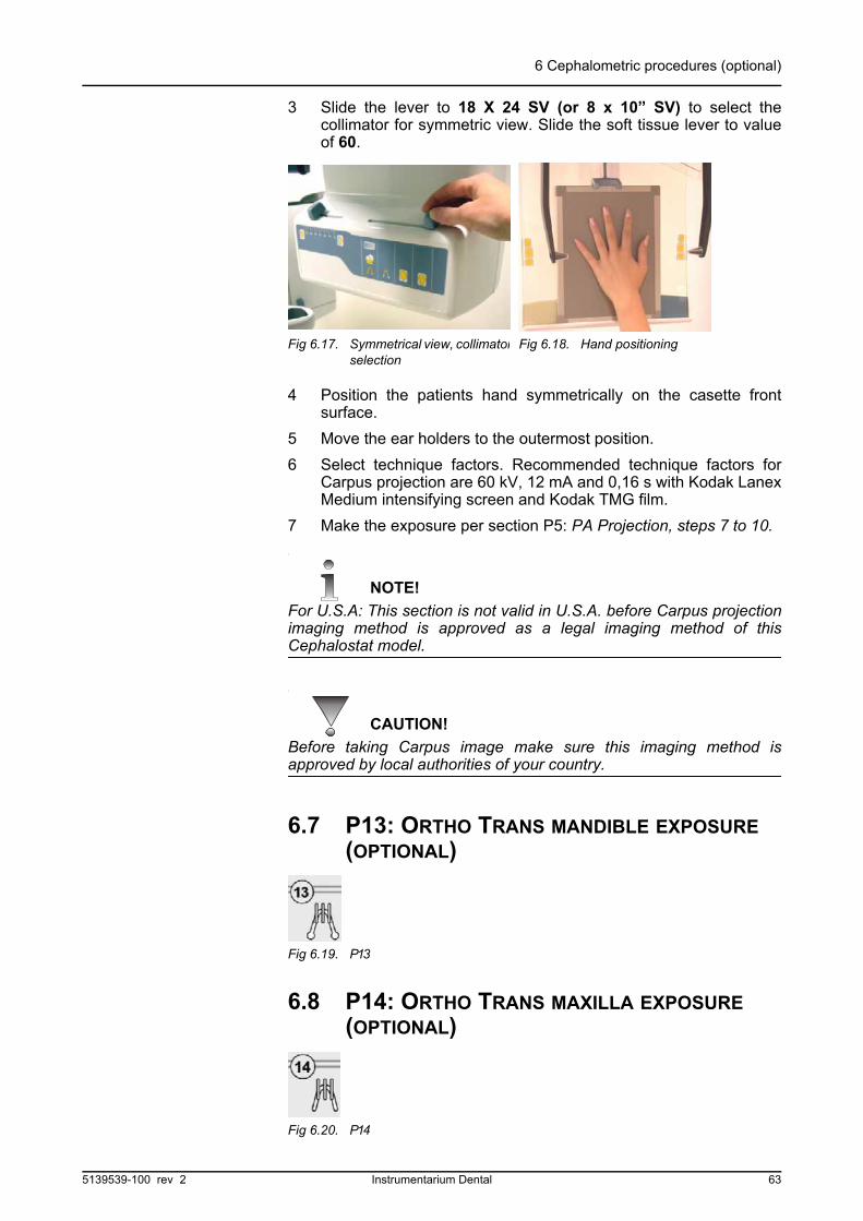
6 Cephalometric procedures (optional)
3 Slide the lever to 18 X 24 SV (or 8 x 10” SV) to select thecollimator for symmetric view. Slide the soft tissue lever to valueof 60.
4 Position the patients hand symmetrically on the casette frontsurface.
5 Move the ear holders to the outermost position.
6 Select technique factors. Recommended technique factors forCarpus projection are 60 kV, 12 mA and 0,16 s with Kodak LanexMedium intensifying screen and Kodak TMG film.
7 Make the exposure per section P5: PA Projection, steps 7 to 10.
NOTE!
For U.S.A: This section is not valid in U.S.A. before Carpus projectionimaging method is approved as a legal imaging method of thisCephalostat model.
CAUTION!
Before taking Carpus image make sure this imaging method isapproved by local authorities of your country.
6.7 P13: ORTHO TRANS MANDIBLE EXPOSURE (OPTIONAL)
6.8 P14: ORTHO TRANS MAXILLA EXPOSURE (OPTIONAL)
Fig 6.17. Symmetrical view, collimatorselection
Fig 6.18. Hand positioning
Fig 6.19. P13
Fig 6.20. P14
5139539-100 rev 2 Instrumentarium Dental 63

6 Cephalometric procedures (optional)
64 Instrumentarium Dental 5139539-100 rev 2
7 Imaging technique
7 Imaging technique
7.1 RECOMMENDED FILM & SCREEN COMBINATIONS
The Orthopantomograph® OP200 is supplied with Kodak Ektavision,Kodak Lanex Regular or Kodak Lanex Medium intensifying screens.The factory default exposure control values are set according tosupplied screens/films.
Other film/screen combinations can be used with the OP200.However, different image characteristics may result and/orreprogramming of the unit may be required.
7.2 AUTOMATIC EXPOSURE CONTROL (AEC)
When the OP200 is turned on, it is set as a default to StandardPanoramic with Automatic Exposure Control. The AEC sensorslocated in the cassette holder will monitor the amount of radiation thefilm is receiving and automatically set the exposure factors for properimage density. After the exposure the adjusted values are shown onthe display.
The AEC will stay engaged with panoramic procedures unless set tomanual mode.
Fig 7.1. AEC density scale
The film density can be changed while keeping AEC engaged:
1 A darker or lighter film can be accomplished without disengagingthe AEC by resetting the automatic exposure density scale on theControl Panel.
2 Press the down button twice to move the flashing light from thestandard panoramic position to the central light on the automaticexposure density scale.
3 To make the film darker, press the left button to move the flashinglight to the right. Each change increases the radiation output byapproximately 12 percent.
4 To make the film lighter, press the cursor button to move theflashing light to the left. Each change decreases the radiationoutput by approximately 12 percent.
Default
Half step darker
One step darker
5139539-100 rev 2 Instrumentarium Dental 65
7 Imaging technique
NOTE!
AEC density is controlled in half steps. A half step between twoindicators is shown with both indicators lit.
7.3 EXPOSURE TECHNIQUE FACTORS
OP200 has a flexibility to use a variety of exposure technique factors,ranging from 57 kV to 85 kV and from 2 mA to 16 mA. The kV/mAvalues used depend on OP200 software settings, i.e. constantcontrast kV setting defined in Pr 52 and also on line voltage.
In the following charts each "ball" represent a kV/mA pair that can beused with the selected line voltage, with imaging programs P1 to P10.Exposure time is fixed with programs P1 to P10.
Exposure factors shown on the control panel are automaticallyselected by the OP200 software based on settings done during theinstallation. These settings can be changed. See User ProgramChapter in OP200 User Manual, Pr 52 for details.
The following charts show examples of exposure values with differentsoftware settings. A "ball" represents a kV/mA value used in Manual
Fig 7.2. Exposure factors with 230 VAC
Fig 7.3. Exposure factors with 110 VAC
Fig 7.4. Example: When kV is lowered and mA increased, the same radiation output level results
66 Instrumentarium Dental 5139539-100 rev 2
7 Imaging technique
mode and a "line" represents kV/mA values which can be selected bythe Automatic Exposure Control (AEC).
7.4 MANUAL MODE
If desired, the exposure technique factors can be set manually with theAEC disengaged. The technique factors can be set either by patientsize or by specific kV and mA factors.
1 To set the unit to manual mode first press the down button onceto move the flashing light from the standard panoramic position tothe AEC (A) position. Then press the right button once to movethe flashing light to manual (M) position.
Fig 7.9. Manual mode
Fig 7.5. Possible exposure values when constant contrast has value of 70 kV and supply voltage is 230 VAC.
Fig 7.6. Possible exposure values when constant contrast has value of 63 kV and supply voltage is 230 VAC.
Fig 7.7. Possible exposure values when constant contrast has value of 70 kV and supply voltage is 110 VAC.
Fig 7.8. Possible exposure values when constant contrast has value of 70 kV and supply voltage is 110 VAC.
5139539-100 rev 2 Instrumentarium Dental 67

7 Imaging technique
2 At this time the light over the juvenile of the pre-programmedexposure factors should be lit. To change the exposure values,first press the down button two times until the flashing light is overthe patient size symbol. To select proper patient size, press theright or left button.
3 To set specific kV and mA technique factors press the downbutton until the flashing light is at the kV and mA section. Bypressing the right or left button the displayed flashing value canbe increased or decreased.
4 Panoramic and Special procedures can use the followingtechnique settings:
NOTE!
kV and mA can be selected independently in Manual mode. With thisoption, kV can be selected in steps of 1 kV. See Service ProgramManual, section Sr 89 COP, option 4 FE for details.
5 Technique factors for patient size symbols can be programmedfor Panoramic and Special procedures. See User ProgramChapter in OP200 User Manual, section Pr 52 for details.
6 Cephalometric procedures use a fixed mA, while kV andexposure time can be selected.
NOTE!
kV and exposure time can be selected independently in manual mode.With this option, kV can be selected in steps of 1 kV. See ServiceProgram Manual, section Sr 89 COP, option 4 FE for details.
Panoramic, TMJ and Sinus Imaging ProceduresTechnique Factors
KV 57 - 60 - 63 - 66 - 70 - 73 - 77 - 81 - 85
mA 2 - 2.5 - 3.2 - 4 - 5 - 6.4 - 8 - 10 - 13 - 16
kV/mA pairs 57/2 - 85/13 Combined values depend on Pr 52 settings.
Exposure time 8.0 - 17.6 s. Fixed for each imaging procedure.
Cephalostat Imaging ProceduresTechnique factors
kV 60, 63, 66, 70, 73, 77, 81, 85
mA 13 mA
s 0.1, 0.12, 0.16, 0.2, 0.25, 0.32, 0.4, 0.5, 0.63, 0.8, 1.0, 1.25, 1.6, 2.0, 2.5, 3.2
68 Instrumentarium Dental 5139539-100 rev 2

7 Imaging technique
7 These programmed values are for guidance only and yourOrthopantomograph® x-ray films may be darker or lighterdepending on patients.
8 To adjust for optimum film quality select one density setting loweror higher in Automatic Exposure Control and one point higher orlower technique factors in Manual Exposure Control. Exposeagain. Consult your dealer for detailed information.
7.5 TEST MODE
The movements of the unit can be performed without radiation. Thismay be useful for children or uncooperative patients to demonstratethe operation prior to taking the exposure.
1 To set the unit to test mode first press the down and right buttonsto move the flashing light from the standard panoramic position tothe AEC (A) position. Then press the right button twice to movethe flashing light to the test mode (T) position.
Fig 7.10. Test mode
2 The unit will now operate without X-ray emission.
NOTE!
Test mode in program 7 for combined lateral TMJ images simulatesonly the first exposure.
3 To return to the AEC (A) mode press the left button twice or once.
7.6 FILM PROCESSING
Proper processing is very important for obtaining high qualityOrthopantomograph® radiographs. It is important that both the darkroom and processing system are in top condition.
Store films in a cool dry dark place in vertical position to reduce filmfog and static. Always use older lot first. Process the film immediatelyafter exposure.
Dark room
Panoramic film is extremely sensitive to light. The dark room cannothave any light leaks of any kind. If in doubt, place a coin on anundeveloped sheet of film for two minutes and then process the film. Ifthe outline of the coin is visible, then light leaks exist which must becorrected.
Along with light leaks an improper safelight can cause film fogging.The recommended safelight is a Kodak GBX-2 located at least 1.2 m(4 ft.) from the working area.
5139539-100 rev 2 Instrumentarium Dental 69
7 Imaging technique
Processing
The OP200 film can be processed in either manual tanks or withautomatic film processor. In both cases the processing chemicalsstrength and temperature are critical to obtaining proper imaging.
The processing chemicals must be changed frequently based on thechemical manufacturer's recommendation. Both time and use cause adegradation of chemical strength.
Manual tanks and some automatic processors need to have thesolutions replenished based on usage. Refer to the manufacturer'srecommendation.
7.7 MEASUREMENTS FROM THE IMAGE
In normal panoramic mode films the vertical dimension must bedivided by a factor of 1.3. Horizontal dimensions should not bemeasured because the horizontal magnification is accurate only in thecenter of focal trough (1.3 in panoramic and TMJ lateral, 1.8 in TMJPA) and changes rapidly when moving away from focal trough.Complete table of magnification factors can be found in ChapterTechnical Specifications at the end of this manual.
WARNING!
In panoramic images the horizontal and vertical magnifications are thesame only in the focal trough. Manufacturer assumes no liability on theaccuracy of the measurements from the x-ray image. Angulation of theobject being imaged affects on the dimensional accuracy on the film.
70 Instrumentarium Dental 5139539-100 rev 2

8 Special features
8 Special features
8.1 QUALITY ASSURANCE
The Orthopantomograph® OP200 can produce a self diagnosing filmfor checking the quality of the exposure and the film processing.
1 Start by establishing a processing standard with new processingchemistry and time and temperature verified.
2 Remove the bite fork with bite fork rod. Insert loaded cassette.
3 Set the primary collimator to the QA position. In OP200 lift thelever to the left and then up for two steps. QA selection isindicated in control panel with lowest kV/mA values (57 kV/2 mA)and a moving indicators in the AEC density scale.Check that the soft tissue filters are in value 60 in cephalostatunit.
4 Press the movement button in the patient positioning panel. Therotating unit turns towards the column.
5 Press and hold the exposure button. The rotating unit will remainstationary while the cassette moves and is exposed withincreasing kV/mA values.
6 Set the primary collimator back to the panoramic position andinsert the bite block.
7 Process the film and place on file for future reference.
8 On a regular basis perform steps 2 through 7.
Fig 8.1. OC200 QA collimator selection
value 60
5139539-100 rev 2 Instrumentarium Dental 71
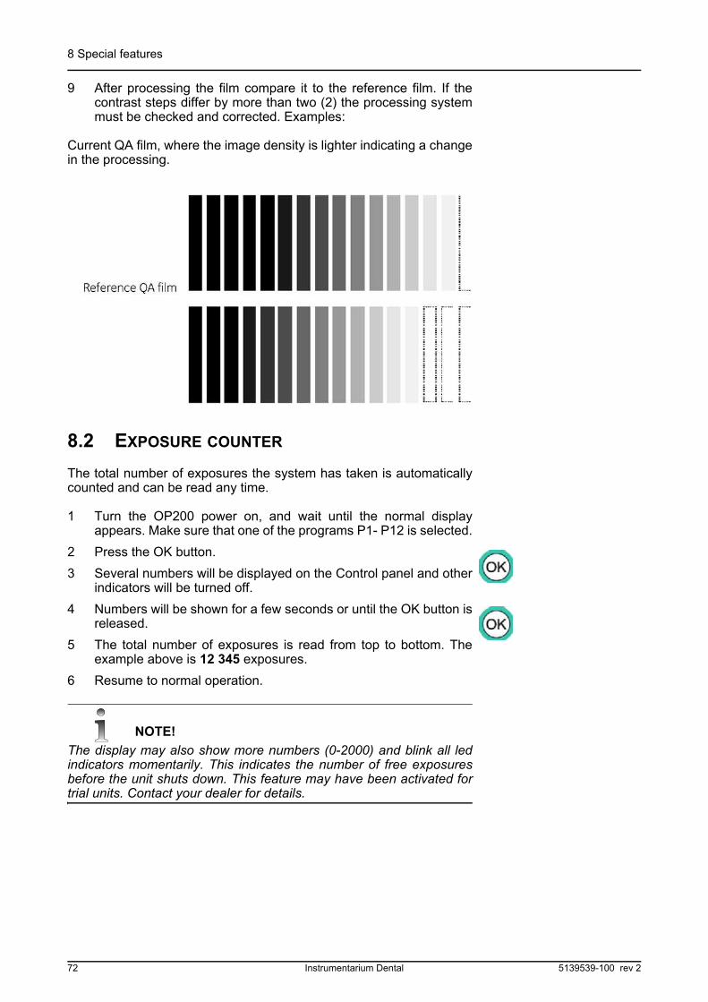
8 Special features
9 After processing the film compare it to the reference film. If thecontrast steps differ by more than two (2) the processing systemmust be checked and corrected. Examples:
Current QA film, where the image density is lighter indicating a changein the processing.
8.2 EXPOSURE COUNTER
The total number of exposures the system has taken is automaticallycounted and can be read any time.
1 Turn the OP200 power on, and wait until the normal displayappears. Make sure that one of the programs P1- P12 is selected.
2 Press the OK button.
3 Several numbers will be displayed on the Control panel and otherindicators will be turned off.
4 Numbers will be shown for a few seconds or until the OK button isreleased.
5 The total number of exposures is read from top to bottom. Theexample above is 12 345 exposures.
6 Resume to normal operation.
NOTE!
The display may also show more numbers (0-2000) and blink all ledindicators momentarily. This indicates the number of free exposuresbefore the unit shuts down. This feature may have been activated fortrial units. Contact your dealer for details.
72 Instrumentarium Dental 5139539-100 rev 2
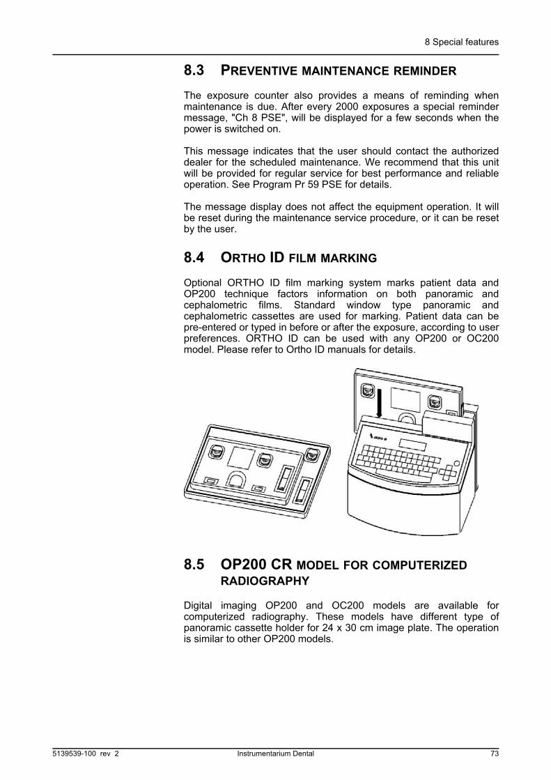
8 Special features
8.3 PREVENTIVE MAINTENANCE REMINDER
The exposure counter also provides a means of reminding whenmaintenance is due. After every 2000 exposures a special remindermessage, "Ch 8 PSE", will be displayed for a few seconds when thepower is switched on.
This message indicates that the user should contact the authorizeddealer for the scheduled maintenance. We recommend that this unitwill be provided for regular service for best performance and reliableoperation. See Program Pr 59 PSE for details.
The message display does not affect the equipment operation. It willbe reset during the maintenance service procedure, or it can be resetby the user.
8.4 ORTHO ID FILM MARKING
Optional ORTHO ID film marking system marks patient data andOP200 technique factors information on both panoramic andcephalometric films. Standard window type panoramic andcephalometric cassettes are used for marking. Patient data can bepre-entered or typed in before or after the exposure, according to userpreferences. ORTHO ID can be used with any OP200 or OC200model. Please refer to Ortho ID manuals for details.
8.5 OP200 CR MODEL FOR COMPUTERIZED RADIOGRAPHY
Digital imaging OP200 and OC200 models are available forcomputerized radiography. These models have different type ofpanoramic cassette holder for 24 x 30 cm image plate. The operationis similar to other OP200 models.
5139539-100 rev 2 Instrumentarium Dental 73
8 Special features
8.6 FREE SELECTION OF KV AND MA
OP200 technique factors are normally selected based on kV targetlevel set with the constant contrast program (Pr 52), where kV and mAvalues are tied to each other. It is possible to configure OP200 so thatkV and mA are selected independently in Manual mode. Pleaseconsult your dealer to activate this software option. When activated,this feature has no effect on the AEC mode and on preprogrammedtechnique factors.
In Manual mode the tube voltage can be selected in steps of 1 kV.When the led indicator for kV/mA values is lit, first kV display isblinking. Select kV value by pressing the right or left button.
NOTE!
Pressing the button longer causes kV to change in larger steps.
Then press the down button; mA display is blinking. Select the mAvalue.
mA can be selected from the fixed table: 2.0, 2.5, 3.2, 4.0, 5.0, 6.4,8.0, 10, 13 and 16.
NOTE!
Cephalostat has a fixed mA value.
NOTE!
If the kV is increased with maximum mA selection, the mA value isautomatically decreased when the product of kV * mA exceeds theallowed X-ray tube rating.
74 Instrumentarium Dental 5139539-100 rev 2

9 Understanding the OP200 radiograph
9 Understanding the OP200 radiograph
Typical OP200 radiograph with anatomical landmarks and structures.
1 hyoid bone2 angle of mandible3 external oblique line4 maxillary tuberosity5 styloid process6 middle cranial fossa7 zygomatic arch8 palate9 orbit10 septa in maxillary sinus11 maxillary sinus12 pterygoid plates13 coronoid process14 articular eminence15 mandibular condyle16 glenoid fossa17 vertebra18 ear lobe19 mandibular canal20 mental foramen21 Sella Turcica
Fig 9.1. Drawing of OP200 radiograph with anatomical landmarks and structures
1
2
5
15 14
216
9
10
20
3
4
11
13
7
17
16
18
812
19
5139539-100 rev 2 Instrumentarium Dental 75

9 Understanding the OP200 radiograph
76 Instrumentarium Dental 5139539-100 rev 2

10 Failure diagnostics
10Failure diagnosticsThe OP200 has many safety functions and features assuring the safeoperation of the equipment. In the event of certain user failures orsystem malfunction the unit will not produce x-rays and a failure codewill be displayed on the Control Panel.
10.1 FAILURE MESSAGES
In case of malfunction, the unit displays a failure message. Variousletters and numbers will be displayed in the technique factors displaypositions next to kV, mA and s, e.g. Ch 6 POS. Failure codeclassification is displayed next to kV. A special 2-digit failure codenumber is displayed next to mA.
10.2 KV DISPLAY
The kV-display indicates the nature of the failure, whether it is causedby user (e.g. exposure button prematurely released by operator),environment (e.g. low line voltage) or protection in the unit (e.g.tubehead too hot), or whether there is a serious defect in the unit,which disables the complete operation (e.g. program memory error):
WARNING!
If the unit is further used, "er" failure may cause malfunction.
10.3 MA DISPLAY
The mA-display indicates the actual numeric failure code by two-digitnumber. Each failure code has a unique number, to differ onemalfunction from another:
Ch Check. A failure caused by the user (e.g. exposure button prematurely released by operator).
Sy Safety. Temporary malfunction or protection in the unit, caused by the unit or environment. Operation is prohibited or terminated to protect the operator, patient and the unit itself. (E.g. the temperature in the tube head assembly is too high due to intensive use). After the corrective action, unit can be used.
Er Error. There is a serious defect in the unit, and the operation is therefore prohibited to protect the operator, patient and the unit itself. (E.g. failure in the CPU Board).
kV Ch Sy Er
mA 1 to 9 20 to 31 40 to 46
5139539-100 rev 2 Instrumentarium Dental 77

10 Failure diagnostics
10.4 TIME DISPLAY
The exposure time display indicates the alphanumeric short formexplanation of the malfunction. This reminds the user or theserviceman of what the actual numeric failure code means, orsometimes numeric information of the malfunction. The display mayalso blink telling more information about the fault, for example in Sy 20where blinking display also tells the waiting time for tube head cooling.
10.5 RESETTING FAILURE
Ch failure codes can be reset by correcting the reason for the failurecode. Ch and Sy failures can be reset by pushing any button in thecontrol panel or in the patient positioning panel. If Sy failure appearsrepeatedly call your local dealer. Exception is Sy 20 failure whichappears when the tube head is too hot and you have to wait forcooling. This is a normal operation if you are exposing a lot and inwarm places.
Er failures can not be reset. Switch the unit off and on, to test whetherthe failure was only temporary.
kV Time display
Ch-failure CAS, COL, POS, rEL, PSE, rEo, or numbers
Sy-failure HHo, Inu, FIL, AEC, EEP, Por,PoC, PoL, PoH, PoU, or numbers
Er-failure CPU, FIL, InP PAy
78 Instrumentarium Dental 5139539-100 rev 2

10 Failure diagnostics
10.6 MULTIPLE FAILURE CODES
In the case of multiple errors press "OK" button to display other failurecodes.
All error messages are explained in detail on OP200 TroubleshootingManual.
Check Interpretation
Ch 1 CAS CASSETTE: Panoramic cassette not installed properly, or not replaced since previous exposure
Ch 2 CAS CASSETTE: Cephalostat cassette not installed properly, or not replaced since previous exposure
Ch 3 COL COLLIMATOR: Collimator not in right position
Ch 4 COL COLLIMATOR: Collimator not in cephalostat position when ceph selected
Ch 5 *** LINE VOLTAGE: Line voltage out of limits- Approximate line voltage (***) displayed in s-display
Ch 6 POS POSITION: System not in Start position, - Start button not pressed prior to QA procedure or - Collimator in QA position when taking a panoramic exposure
Ch 7 rEL EXPOSURE SWITCH: Exposure button prematurely released by operator- Blinking display tells also exposure time (***) in s-display
Ch 8 PSE PREVENTATIVE SERVICE: Preventative service reminder after 2000 exposures
Ch 9 rEo REMOTE EXPOSURE: Exposure was initiated from control panel, while remote exposure has been selected.
Ch 11 PAr EXPOSURE VALUES: (parameters) out of range.
Ch 12 dCC DOSE CALIBRATION: constant missing or out of limits.
5139539-100 rev 2 Instrumentarium Dental 79

10 Failure diagnostics
80 Instrumentarium Dental 5139539-100 rev 2

11 Diagnosing image quality problems
11Diagnosing image quality problemsHigh quality radiographs with sharp contrast and good detail presentoptimum diagnostic information. Images with less quality are usuallythe result of one or more common problems, which are discussedhere.
11.1 PATIENT POSITIONING
Problem Possible Cause Remedy
Incisors and canines narrow and unsharp. Overshadow in molar and premolar areas. Rows of teeth are compressed.
1 Occlusal correction of focal trough set was too far posterior
2 Image layer light was not obeyed
3 Bite block was not used
1 Check patient positioning with light lines and occlusion correction buttons
2 Check patient positioning with light lines and occlusion correction buttons
3 Insert bite block
Incisors and canines wide and unsharp. Rows of teeth widened.
1 Occlusal correction of focal trough set was too far anterior
2 Image layer light was not obeyed
3 Bite block was not used
1 Check patient positioning with light lines and occlusion correction buttons
2 Check patient positioning with light lines and occlusion correction buttons
3 Insert bite block
Teeth appear wider on one side and narrower on the opposite. Ramus widths are different on opposite sides.
1 Midsagittal line was not obeyed
2 Patient's head was not in center position
1 Check patient's mid sagittal plane with light line
2 Check that patient's head is centered
AUP
ABACK
5139539-100 rev 2 Instrumentarium Dental 81

11 Diagnosing image quality problems
The shadow of hard palate is exposed over maxillary molars. Row of teeth has a wavy appearance. TM joints are exposed outward. Image is not "smiling". Mandible is imaged sharper than maxilla.
Patient head was tilted back
Check FH plane
Rows of teeth curved upwards. Mandibular incisors are unsharp. TMJ joints exposed high and are often cut off from the image. Image is "smiling" too much.
Patient head was tilted forward
Check FH plane
Middle area of the image too bright and unsharp. Spine shadow.
1 Patient's neck was not stretched
2 kV compensation was not used or LOW compensation was used with Large adult patient
1 Stretch patient's neck
2 Enable or increase kV compensation
Rows of teeth overexposed.
Tongue was not against the roof of palate.
Ask patient to swallow and place tongue against the roof of palate.
Problem Possible Cause Remedy
AUP
ANECK
82 Instrumentarium Dental 5139539-100 rev 2

11 Diagnosing image quality problems
11.2 FILM DENSITY AND CONTRAST
TMJ's exposed on different heights on image. Bilateral distortion in molar and premolar regions.
1 Patient was tilted to one side
2 Midsagittal light line was not obeyed.
1 Check midsagittal plane and center patient's head.
2 Check mid sagittal plane and center patient's head.
Rows of teeth exposed too high. TMJ's cut off.
1 Chin was not resting on chin support
2 Patient was positioned too high
1 Check patient positioning and type of bite fork rod.
2 Check patient positioning and type of bite fork rod.
Rows of teeth exposed too low. Mandible not exposed completely to the image.
Chin rest was not used with bite fork.
Install chin rest.
Problem Possible cause Remedy
Images are too light 1 AEC density setting was too low.
2 Manual technique factors used were too low.
3 A problem with the processing.
4 AEC control or beam alignment was misadjusted
1 Adjust the density to a higher value.
2 Increase technique factors
3 Make the "QA" film and check the processing (chemicals, temperature and time)
4 Call service.
Problem Possible Cause Remedy
5139539-100 rev 2 Instrumentarium Dental 83
11 Diagnosing image quality problems
Images are too dark 1 AEC density setting was too high.
2 Manual technique factors used were too high.
3 A problem with the processing.
4 AEC control was misadjusted
5 Leaded cassette was used with AEC.
1 Adjust density to a lower value.
2 Increase technique factors.
3 Check the processing.
4 Call service.
5 Check the cassette. Use one without lead.
Lack of image contrast
1 kV used was too high
2 Film-screen not optimum
3 Fogged film
1 Lower the kV setting. See P.52 CCO for details.
2 Check the film and screens.
3 Check the film. Process a piece without radiation.
Image is fogged. Metal fillings don't appear as bright unexposed areas.
1 Film was re-exposed during the processing
2 Light leak in dark room
3 Safety light was not appropriate to film in use
4 Useless film (wrong storage or expired lot)
1-4) Check your film lot and dark room
One side of the film overexposed.
1 Film has been previously exposed to light
2 Light leak in dark room
3 Cassette was not properly closed
1 Check your film inventory and dark room
2 Check your film inventory and dark room
3 Check cassette locking
Problem Possible cause Remedy
84 Instrumentarium Dental 5139539-100 rev 2
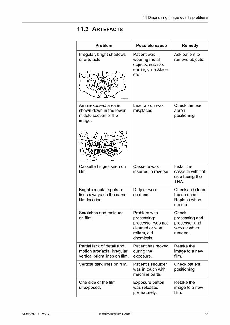
11 Diagnosing image quality problems
11.3 ARTEFACTS
Problem Possible cause Remedy
Irregular, bright shadows or artefacts
Patient was wearing metal objects, such as earrings, necklace etc.
Ask patient to remove objects.
An unexposed area is shown down in the lower middle section of the image.
Lead apron was misplaced.
Check the lead apron positioning.
Cassette hinges seen on film.
Cassette was inserted in reverse.
Install the cassette with flat side facing the THA.
Bright irregular spots or lines always on the same film location.
Dirty or worn screens.
Check and clean the screens. Replace when needed.
Scratches and residues on film.
Problem with processing: processor was not cleaned or worn rollers, old chemicals.
Check processing and processor and service when needed.
Partial lack of detail and motion artefacts. Irregular vertical bright lines on film.
Patient has moved during the exposure.
Retake the image to a new film.
Vertical dark lines on film. Patient's shoulder was in touch with machine parts.
Check patient positioning.
One side of the film unexposed.
Exposure button was released prematurely.
Retake the image to a new film.
AJEWEL
5139539-100 rev 2 Instrumentarium Dental 85

11 Diagnosing image quality problems
Lightning like pattern on film.
1 Discharge of static electricity.
2 Film was loaded by sliding it over screens.
1 Load the film without sliding it over screens.
2 Check dark room humidity level.
An unexposed 10x50 mm area in the film corner.
Window cassette for Ortho ID was used. Area is for film marking.
None.
Right and left film sides are unexposed. TMJ's are not shown.
Orthogonal procedure was mistakenly used.
Select correct panoramic procedure.
CEPH: Double image on film.
Cassette has not been replaced after previous exposure.
Reload or replace the cassette.
CEPH: Unexposed rectangular on the image.
1 Cassette was not in right place.
2 Ceph collimator was not correctly selected.
1 Align the cassette according to the ceph view.
2 Select correct collimation.
CEPH: Lateral view has 2 ear holder pins.
1 Cephalostat lock was not locked
2 Ear holders were misaligned
1 Lock it
2 Call service
QA: Light horizontal line on film
Bite block was left on place
Remove the bite block Note: QA film can be used.
Problem Possible cause Remedy
86 Instrumentarium Dental 5139539-100 rev 2
11 Diagnosing image quality problems
11.4 UNIT OPERATION
Problem Possible cause Remedy
READY not lit. 1 Unit is not ready for exposure.
1 Check the collimator,program selection andcassette. If the unit isstill not ready,momentarily pressexposure button: Failuremessage will bedisplayed. Make thecorrective measures.
Patient's back head is touching the x-ray tube during the exposure.
1 Patient'sheadinclinationwas notcorrect
2 Patient is toobig for theunit.
3 Patient hasslumped.
Process the film. If the film is not accetable then:
1 Check the head positionand retake the film.
2 Check the patientpositioning. Make theexposure even thoughthe head may touch thetube head.
Patient's shoulders are touching the x-ray tube or cassette holder.
Patient is too big for the unit. Wide shoulders.
Reverse patient's hands on handles: left to right side handle and vice versa.
5139539-100 rev 2 Instrumentarium Dental 87

11 Diagnosing image quality problems
88 Instrumentarium Dental 5139539-100 rev 2

12 How to use the user programming mode
12 How to use the user programming mode
12.1 GENERAL
The Orthopantomograph® OP200 is a panoramic x-ray equipment withthe possibility of linear tomography programs for producinglongitudinal and cross-sectional tomograms of the dentition. Thissoftware can be used with any OP200 or OC200 model.
Software is divided into two parts. User programs (“Pr”) are accessibleby the user and they have features for configuring the unit for daily useand for changing technique factors to optimize the image quality.
Maintenance and Service programs (“Sr”) are for technical people forinstallation and service. Tools are required to access “Sr” programs.
This manual covers the features of the “Pr” programs OP200. Pleaserefer to the OP200 Service Program Manual for “Sr” program features.
12.2 INSTALLATION & UNIT CONFIGURATION PROGRAMS
“PR” USER PROGRAMS
Pr51PUS
POWER UP SETTINGS: Select imaging program and exposure control mode for the control panel display after OP200 power-up.
Pr54Arn
ROTATING UNIT AUTORETURN: Easy patient exit after the exposure by returning the rotating unit to the nearest patient exit position.
Pr55HUP
CASSETTE HOLDER AUTOLIFT: Lifts automatically the cassette holder after inserting the panoramic cassette.
Pr56HLI
CASSETTE HOLDER VERTICAL LIMIT: Low ceiling application to limit cassette holder vertical travel below the column top.
Pr57Hon
HOME SIDE FOR EXPOSURE START: Select exposure in one direction, clockwise or counterclockwise rotation , or exposure in both directions.
5139539-100 rev 2 Instrumentarium Dental 89

12 How to use the user programming mode
12.3 PROGRAMS AFFECTING TO IMAGE QUALITY
12.4 OTHER PR PROGRAMS
Pr65doS
CONFIGURE TIME/DOSE DISPLAY:Time/dose display displays according to the selection seconds or dose during the image capturing.
“PR” USER PROGRAMS
Pr50LAY
LINEAR TOMOGRAPHY IMAGE LAYER: Select image layer thicknesses, number of images and the choice of longitudinal and / or transversal images for three areas of interest (anterior, premolar and molar)
Pr51PUS
POWER UP SETTINGS: AEC mode or Manual mode and the default imaging program for the control panel display after OP200 power-up.
Pr52GCo & PCo
CONSTANT CONTRAST & DENSITY: Set general technique factor and program spesific offset for all imaging programs.
Pr 58Con
VERTEBRAE SHADOW COMPENSATION: kV-compensation at spinal column OFF = no compensation. LO = compensation by one mA stepsHI = compensation by two mA stepsASC = Automatic Spine Compensation
“PR” USER PROGRAMS
Pr53nor
RESUME NORMAL SETTINGS: Reset user program memory parameters for selected “Pr” programs.
Pr59PSE
PREVENTATIVE SERVICE MESSAGE: Clear, disable or enable the Preventative Service Request message after installation, maintenance or service.
Pr60bEP
PANEL BEEP: Enable or disable the response “beep” when pushing any button in the display panels.
Pr61CLC
CLEAR EXPOSURE COUNTER: Clear the resetable exposure counter.
Pr62Err
LAST FAILURE CODE: Display of the last storable failure code for this unit.
“PR” USER PROGRAMS
90 Instrumentarium Dental 5139539-100 rev 2

12 How to use the user programming mode
12.5 HOW TO USE THE USER PROGRAMMING MODE
1 To begin the setting switch the OP200 power on.
2 Wait for a moment, while the OP200 performs a self check. Aftera tone the default operating mode is displayed on the controlpanel. Information is defined in user program Pr 51 PUS, whichguidelines are described in the next chapter.
NOTE!
Er 45 InP shall be displayed if the exposure button, any of the buttonsin the patient positioning panel or any of the buttons in the controlpanel is pressed when switching the OP200 D power on.
3 Press and keep down the OK button until the user programmingmode is displayed after the tone, e.g. “PR 52 GCO”.
NOTE!
If the button is released too early, program resumes to the normaloperation mode. In that case start again from step 3.
4 Use up and down buttons to select one of the Pr programs. PressOK button to confirm the selection. The program parameters shallbe displayed.
5 Use up and down buttons to select the option in the program.
6 Use left and right buttons to change the settings. Follow theguidelines for each “ Pr “ program described in the next chapter.
7 Press OK button once to store the changes and exit the userprogram.
NOTE!
If you change the parameters and forget to press OK or switch thepower off, the storing of any changes failed.
8 Press OK button for a while to exit from the user programmingmode. The tone is heard as the normal display is resumed.Another way to exit the user programming mode is to switchOP200 power off, wait for 15 s, and switch the power on again.
Pr66COU
COUNTERS: Reset and view various exposure counters.
“PR” USER PROGRAMS
5139539-100 rev 2 Instrumentarium Dental 91
12 How to use the user programming mode
EXAMPLE 1: A user wants to change the constant dose settings of theunit.
9 Press and keep down OK button to enter the user programmingmode. The tone is heard while pressing. Use up and downbuttons to select PR 52 gCO and press OK. Use up and downbuttons to select the dose value when time display starts blinking.Set the desired density value with right and left buttons. Use OKbutton to store the changes. A text PASS will display on controlpanel to confirm the setting been saved. Press and keep downOK to return to the normal operating mode.
92 Instrumentarium Dental 5139539-100 rev 2
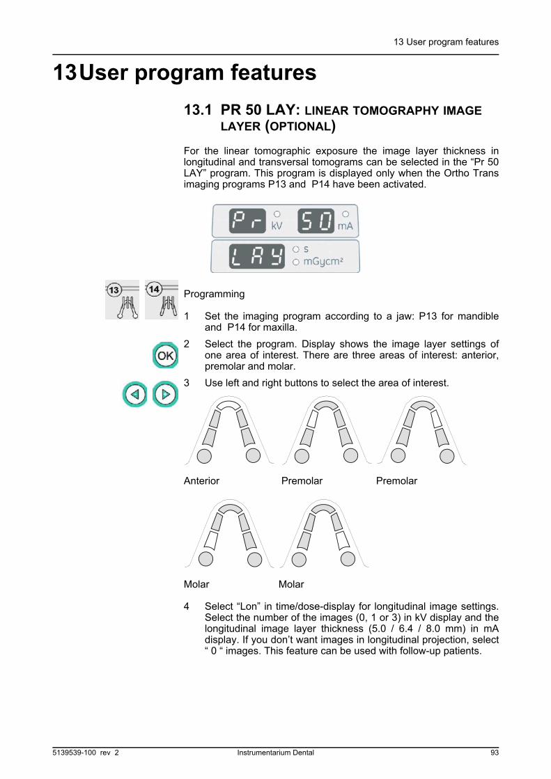
13 User program features
13User program features
13.1 PR 50 LAY: LINEAR TOMOGRAPHY IMAGE LAYER (OPTIONAL)
For the linear tomographic exposure the image layer thickness inlongitudinal and transversal tomograms can be selected in the “Pr 50LAY” program. This program is displayed only when the Ortho Transimaging programs P13 and P14 have been activated.
Programming
1 Set the imaging program according to a jaw: P13 for mandibleand P14 for maxilla.
2 Select the program. Display shows the image layer settings ofone area of interest. There are three areas of interest: anterior,premolar and molar.
3 Use left and right buttons to select the area of interest.
4 Select “Lon” in time/dose-display for longitudinal image settings.Select the number of the images (0, 1 or 3) in kV display and thelongitudinal image layer thickness (5.0 / 6.4 / 8.0 mm) in mAdisplay. If you don’t want images in longitudinal projection, select“ 0 “ images. This feature can be used with follow-up patients.
Anterior Premolar Premolar
Molar Molar
5139539-100 rev 2 Instrumentarium Dental 93

13 User program features
5 Select “trv” in time/dose-display for transversal image settings.Select the number of the images (0, 1 or 3) in kV display and thetransversal image layer thickness (2.0 / 2.5 / 3.2 / 4.0 / 5.0 / 6.4mm) in mA display. If you don’t want images in transversalprojection, select “ 0 “ images.
NOTE!
2 mm image layer thickness is only available in one imagingprojection. See the following tables for details.
6 Select the number of the images and the image layer thicknessesfor other regions of interest. Repeat steps 2 to 4.
PR 50 LAY: IMAGE LAYER THICKNESSES & NUMBER OF LAYERS
Image Layer Thickness(mA display)
Longitudinal Lon (time/dose display)
Transversal trv(time/dose display)
Number of layers(kV display)
Number of layers(kV display)
2.0 mm n/a n/a 1 3
2.5 mm n/a n/a 1 3
3.2 mm n/a n/a 1 3
4.0 mm n/a n/a 1 3
5.0 mm 1 3 1 3
6.4 mm 1 3 1 3
8.0 mm 1 3 n/a n/a
0 mm = no images
0 0
94 Instrumentarium Dental 5139539-100 rev 2

13 User program features
NOTE!
An error message will be generated during exposure, if bothlongitudinal and transversal image layers are set to “ 0 “.
7 Press OK button once to store the changes and exit the userprogram. “ Pr 50 LAY “ is displayed again. Select anotherprogram or exit the user programming mode.
13.2 PR 51 PUS: POWER UP SETTING
The user can set the imaging program and exposure control mode for the control panel to appear after switching the OP200 power on. This will make the use of OP200 even easier and reduce the total imaging time, when the most frequently used imaging program and AEC or Manual mode are automatically selected and the operator can concentrate on patient positioning.
Programming:
1 Select program “ Pr 51 PUS “ and press OK button. Control panelshows current power-up display, e.g.– Standard panoramic procedure (Program 1) is chosen– Automatic Exposure Control “ A “ and density setting in the
middle are chosen
2 Change the power up setting. Select one of the imagingprograms, Program 1 to 14.
5139539-100 rev 2 Instrumentarium Dental 95

13 User program features
3 Select the exposure control mode: AEC, Manual or Test (A, M orT).
NOTE!
AEC can be selected for the panoramic programs (P1 - P5) and forlinear tomography programs P13 and P14.
NOTE!
AEC can be selected only if all the regions of interest (anterior,premolar, molar) are chosen.
4 Press OK button once to store the changes and exit the userprogram.
13.3 PR 52 GCO AND PR 52 PCO: CONSTANT CONTRAST & DENSITY SETTINGS
OP200 image quality can be controlled by setting the techniquefactors for film / screen combination and per customer preferences.This is done by giving general contrast and density parameters for allimaging programs with PR 52 GCO and adding an offset value forindividual imaging program by PR 52 PCO if necessary. QualityAssurance (QA) film will be used to select optimum image density.
AEC and Manual mode technique factors are related to each other:the selection of contrast (kV level) and density (dose level) will fix theAEC and Manual mode technique factors. Preprogrammed patient
96 Instrumentarium Dental 5139539-100 rev 2
13 User program features
size symbols have only one reference, and this reference is tied toAEC settings. The technique factors’ relation between patient sizesymbols is fixed
Use Quality Assurance film to obtain correct general density setting forgCO. QA film sent from the factory has columns marked with O.D.(Optical Density). QA film column representing about 1.3 - 1.4 O.D. isa reference. Make the QA exposure at site and process the film. Finda column that has the same O.D. or closest with the reference film 1.3O.D. Calculate the order of this column starting from the lightestcolumn and set this value, e.g. 6, for general density (see figure).There are 15 columns in the QA film.
NOTE!
These technique settings are for guidance. If the patient images arelighter or darker than desired, you may have to change the contrastand / or density according to the user preferences.
Example: If general density is 5 and P1 has contrast “ 66 “ and offset “0 “ this means that P1 AEC exposure with middle density scale has 66kV /10 mA starting value. In Manual Control mode preprogrammedpatient size symbols have values 66/5, 66/8, 66/10 (as AEC) and 66/13.
PR 52 gCO: General density
All imaging programs Density value (default)1-15 (5) adjustable by 0,5 steps
5139539-100 rev 2 Instrumentarium Dental 97
13 User program features
NOTE!
Another QA film is needed if these programs use different screen-filmcombination or cassette.
.
NOTE!
Grid cassette requires 2 steps higher density setting than the standardcassette.
PR 52 PCO: CONTRAST & DENSITY
Imaging Program
Description of Imaging Program
Constant Contrast value
kV display (default)
Density offset value
Time display
(default 0)
P1 Panoramic 57 - 85 (66) 0
P2 Panoramic 57 - 85 (66) 0
P3 Panoramic 57 - 85 (66) 0
P4 Panoramic 57 - 85 (66) 0
P5 Panoramic 57 - 85 (66) 0
P6 TMJ 57 - 85 (66) 0
P7 TMJ 57-85 (66) 0
P8 TMJ 57 - 85 (66) 0
P9 TMJ 57 - 85 (66) 0
P10 Sinus Maxillary 57 - 85 (66) 0
P11 Cephalometric 60 - 85 (77) 0
P12 Cephalometric 60 - 85 (77) 0
P13 Ortho Trans mandible
57 - 85 (66) 0
P14 Ortho Trans maxilla
57-85 (66) 0
98 Instrumentarium Dental 5139539-100 rev 2

13 User program features
NOTE!
Use left and right buttons to choose the regions of interest (anterior,premolar, molar) in the imaging program P13 and P14.
Programming:
1 Select program “Pr 52 PCO” and press OK. One of the programs(e.g. P1) is selected. KV display shows the current constantcontrast kV level and the time/dose-display shows the densityoffset from reference for this imaging program.
2 Select the imaging program options by pressing up or downbutton. When the P1 (or other imaging program) is selectedchange the program by pressing left or right button.
3 Select or change the constant contrast value for this imagingprogram by pressing down button. The led of kV display isblinking. Use left or right buttons to change this value.
NOTE!
This kV value will depend on the film-screen combination used. ForKodak Lanex Regular - TMG combination values 66 in P1- P5 and 77 in P11 - P12 and 63 in P13 and P14 are recommended.
4 Select the density level offset if needed for this imaging programby pressing down button. The led of mA display is blinking. Useleft or right buttons to change this value. The offset can be from -3 to +3 with half step increments calculated from general density.
NOTE!
These technique settings are for guidance. If the patient images arelighter or darker than desired, you may have to change the contrastand / or density according to the user preferences.
Example: If general density is 5 and P1 has contrast “ 66 “ and offset “0 “ this means that P1 AEC exposure with middle density scale has 66kV /10 mA starting value. In Manual Control mode preprogrammedpatient size symbols have values 66/5, 66/8, 66/10 (as AEC) and 66/13.
5 If you want to change contrast and density for other programs,repeat steps 2, 3 and 4. Another QA film is needed if theseprograms use different screen-film combination or cassette.
6 Press OK button to store the changes and exit the user program.
5139539-100 rev 2 Instrumentarium Dental 99

13 User program features
13.4 PR 53 NOR: RESUME NORMAL SETTINGS
Normal settings for all parameters can be resumed. This can be done after service or in the case of CPU board memory problem. Error counter and exposure counters are not affected.
Programming:
1 Select program “Pr 53 nor”. Time display shows “ OFF “ or “ on“. If you by mistake enter this program, select “ OFF “ to exitwithout changes. It is recommended to record “ Pr “ settings priorto using this program.
2 Press left button, if you don’t want to resume normal settingvalues. “ OFF “ is displayed.
3 Press right button to resume normal settings. “ on “ is displayed.This program will affect to the following User programs
Pr 50 LAy: mandibular maxilla
trv anttrv pretrv mol
3.03.03.0
4.04.04.0
lon antlon prelon mol
3.03.03.0
4.06.06.0
Pr 51 PUS: P1 blinking, AEC, density in the middle
Pr 52 gCO: See default values in the section PR 52 gCO and PCO
Pr 53 Nor: OFF or on
Pr 54 Arn: on
Pr 55 HUP: on
Pr 56 HLI: on
Pr 57 HON: L -, if positioning lights on the left sider -, if positioning lights on the right side
Pr 58 CON: P1-P5 (ASC)
Pr 59 PSE: on
Pr 60 bEP: on
Pr 61 CLC: 0
Pr 62 Err: CH 05 ooo
100 Instrumentarium Dental 5139539-100 rev 2
13 User program features
These parameters have to be checked for configuring OP200 for dailyuse.
4 Press OK button to store the changes and exit the user program.
13.5 PR 54 ARN: ROTATING UNIT AUTORETURN
After the exposure the unit can keep moving and then stop so that thepatient has an easy exit from the unit. The return movement of therotating unit after the exposure can be enabled or disabled. Note thatthe rotating unit can always be returned by pressing the patientpositioning button in the patient positioning panel.
NOTE!
At any time if the exposure button is released OP200 stopsmovements immediately.
Programming:
1 Select program “ Pr 54 Arn “. Time display shows “ OFF “ or “on “.
2 Normally rotating unit autoreturn is “on” after the exposure. Thisenables easy exit for the patient. If “ off “ is displayed, press rightbutton to get “ on “ displayed.
3 Press left button, if you don’t want to rotating unit to return to thenearest patient positioning position after the exposure. “ OFF “ isdisplayed. In this case the cassette rack stays behind the patientafter the exposure.
4 Press OK button to store the changes and exit the user program.
13.6 PR 55 HUP: CASSETTE HOLDER AUTOLIFT
Cassette holder can be programmed to lift up automatically when thepanoramic cassette has been inserted in its place.
Pr 66 COU: us Er 0
5139539-100 rev 2 Instrumentarium Dental 101

13 User program features
Programming:
1 Select program “ Pr 55 HUP “. Time display shows “ OFF “ or “on “.
2 Press right button, when the automatic lifting up of cassette rackis requested. “ on “ is displayed.
NOTE!
When the panoramic cassette is inserted, a message “UP CAS“ isdisplayed and the unit aligns itself for patient positioning and raisesthe cassette holder.
3 Press left button, when the automatic lifting up of cassette holderis not needed. “ OFF “ is displayed. In this case the cassetteholder can be lifted by pressing the button in the positioningpanel.
4 Press OK button to store the changes and exit the user program.
13.7 PR 56 HLI: CASSETTE HOLDER VERTICAL LIMIT
In the rooms with limited ceiling height the cassette holder vertical limitcan be activated. This option makes the cassette holder to always staybelow the height of the column.
Programming:
1 Select program “ Pr 56 HLI “. Time display shows “ OFF “ or “on “.
2 Press right button, when the cassette holder vertical limit isrequested. “ on “ is displayed.
3 Press left button, when the cassette holder vertical limit is notneeded. “ OFF “ is displayed. Now the cassette holder can raiseover the column height.
4 Press OK button to store the changes and exit the user program.
102 Instrumentarium Dental 5139539-100 rev 2
13 User program features
13.8 PR 57 HON: CASSETTE LIFT SIDE
The home side i.e. the patient positioning side of the unit can beselected. If the unit is supplied with one patient positioning panel, thehome side is the same as the panel side. With the Ortho Trans optionand two positioning panels the home side is selected with thisprogram.
OP200 operates normally uni-directionally, i.e. the exposure isenabled while the rotating unit moves clockwise (left-handed unit “LL”or “LR”) or counterclockwise (right-handed unit or “RL” or “RR”) andafter the exposure the rotating unit returns to starting position.
In OP200 a bi-directional exposure is also possible, where the unit canmake an exposure both clockwise and counterclockwise, and noreturn sequence is necessary after the exposure.
Programming:
1 Select program “ Pr 57 Hon “. Display shows one of the choices:“ -r- “, “ -L- “ or “ L=r “.
2 OP200 with Frankfort and layer light on the left side of the unit: The display should have “ -L- “. If not, press left or right buttons toselect “ -L- “.
3 OP200 with lights on the right side: the display should show “ -r-“. If not, select “ -r- “.
4 Optionally OP200 models can have dual set of positioning lightsused in programs P1-P10. Such models have patient positioningon both sides of the unit and the exposure can start on either sideof the unit. In this case, select “ L=r “.
5 Press OK button to store the changes and exit the user program.
Pr 57 Hon Positioning Lights
Rotation for exposure
OP/OC200 type
- r - Right side of unit
Counterclockwise (ccw)
RR, RL
- L - Left side Clockwise (cw) LL, LR
L = r Dual, on both sides
(cw) -> (ccw) -> (cw) - ->
DL, DR
5139539-100 rev 2 Instrumentarium Dental 103
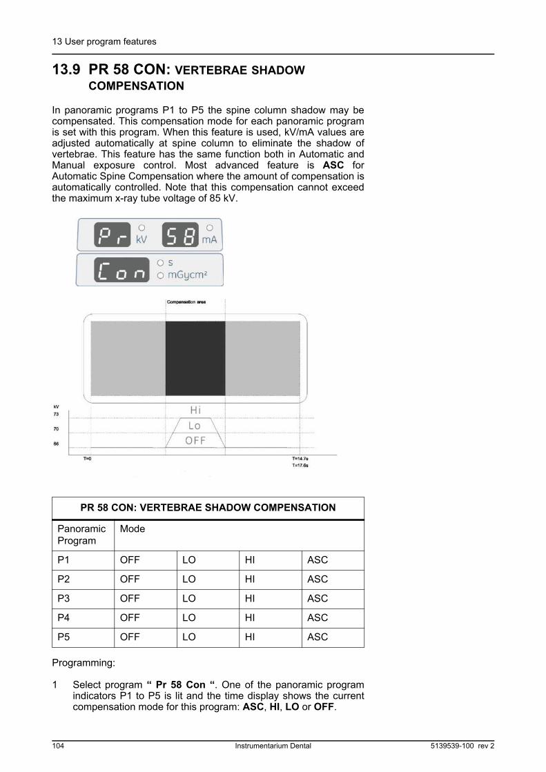
13 User program features
13.9 PR 58 CON: VERTEBRAE SHADOW COMPENSATION
In panoramic programs P1 to P5 the spine column shadow may becompensated. This compensation mode for each panoramic programis set with this program. When this feature is used, kV/mA values areadjusted automatically at spine column to eliminate the shadow ofvertebrae. This feature has the same function both in Automatic andManual exposure control. Most advanced feature is ASC forAutomatic Spine Compensation where the amount of compensation isautomatically controlled. Note that this compensation cannot exceedthe maximum x-ray tube voltage of 85 kV.
Programming:
1 Select program “ Pr 58 Con “. One of the panoramic programindicators P1 to P5 is lit and the time display shows the currentcompensation mode for this program: ASC, HI, LO or OFF.
PR 58 CON: VERTEBRAE SHADOW COMPENSATION
Panoramic Program
Mode
P1 OFF LO HI ASC
P2 OFF LO HI ASC
P3 OFF LO HI ASC
P4 OFF LO HI ASC
P5 OFF LO HI ASC
104 Instrumentarium Dental 5139539-100 rev 2
13 User program features
2 Press right or left button to change the compensation mode forthis imaging program:
“OFF” disables this feature. It can be selected with pediatric patients.When disabled, the same kV value is used during the exposure cycle.
“LO” compensates the spine shadow by one mA-step (Lo = 1). It is selected with most of the patients.
“HI” compensates the spine shadow by two mA-steps (Hi = 2). It can be selected with large patients.
Select “ASC“ for Automatic Spine Compensation (0 < ASC < 2). MA compensation will be determined automatically.
Sequence of the mA values:
2.0 - 2.5 - 3.2 - 4.0 - 5.0 - 6.4 - 8.0 - 10.0 - 13.0 - 16.0.
NOTE!
Value 13.0 mA showed on the mA display is precisely 12.5 mA.
Example of use 1: Onset is 66 kV / 8 mA. a) With Lo (one step)selection the new value shall be 66 kV / 10 mA. b) With Hi (two step)selection the new value shall be 66 kV / 13 mA.
Example of use 2: Onset is 60 kV / 13 mA. a) With Lo (one step)selection the new value shall be 60 kV / 16.0 mA. b) With Hi (two step)selection the new value shall be 63 kV / 16.0 mA, as the sequence ofthe mA values doesn’t get any further than 16.0 mA.
3 Change the compensation mode for other panoramic programs.Press up button to select another imaging program. Press downbutton to select the compensation mode. Press right or left buttonto change the compensation mode (Hi, Lo, Asc or Off) for thisimaging program.
4 Press OK button once to store the changes and exit the userprogram.
5 Change the compensation mode for other panoramic programs.Press up button and select another panoramic program. Pressdown button and repeat step 2.
6 Press OK button once to store the changes and exit the userprogram.
5139539-100 rev 2 Instrumentarium Dental 105
13 User program features
13.10 PR 59 PSE: PREVENTATIVE MAINTENANCE REMINDER
OP200 has a feature to inform the user every 2000 exposures aboutpreventative service. When activated, a Preventative MaintenanceRequest message “Ch 8 PSE“ is displayed automatically after powerup -sequence, when cumulative 2000 exposures have been taken andit come again until it is cleared with this program. This message hasno affect to the unit’s operation.
Programming:
1 Select program “Pr 59 PSE“. Time display shows “ OFF “ or “on “.
2 Press right button to enable this reminder feature. “ on “ isdisplayed.
3 If you don’t want to use this reminder feature, set “ off “ to bedisplayed by pressing left button.
4 Press right button to reset this counter or to clear the “ Ch 8 PSE“ service message. “ rES “ is displayed. Next “ Ch 8 PSE “service message will come after 2000 exposures.
5 Press OK button to store the changes and exit the user program.
13.11 PR 60 BEP: PANEL BEEP
Enables the response “beep” when pushing any button in the OP200panels. This feature can be disabled, if needed for maintenance andtesting.
Programming:
1 Select program “ Pr 60 bEP “. Time display shows “ OFF “ or “on “.
2 Press left button, if you don’t want to hear the beep-signal afterpushing the panel buttons. “ OFF “ is displayed.
3 Press right button, if you want to enable the beep-signal afterpushing the panel buttons. “ on “ is displayed.
4 Press OK button to store the changes and exit the user program.
106 Instrumentarium Dental 5139539-100 rev 2
13 User program features
13.12 PR 61 CLC: CLEAR EXPOSURE COUNTER
The left and right buttons toggle between zero and the currentclearable exposure count (user counter, “trip meter”). The exposurecount is the same as displayed when entering the user programmingmode. Toggling to ”0” and pressing ”OK” will clear the exposure count.
Programming:
1 Select program “ Pr 61 CLC “. MA and time displays show thetotal number of exposures since last clearing of this counter.
2 Press left button to clear the counter value to zero afterInstallation or Maintenance. “ 0 “ is displayed.
3 Press right button, if you don’t want to clear the exposure countervalue to zero. Number of exposures taken is displayed on thetime/dose time display.
4 Press OK button once to store the changes and exit the userprogram.
13.13 PR 62 ERR: LAST FAILURE CODE
OP200 stores in the memory the last storable failure code information.A new OP200 may have a failure code already in this memory and thisis considered normal.
Programming:
1 Select program “ Pr 62 Err “. OP200 displays the last failurecode. If there are no failure codes stored in the memory, displaysshow “ Ch 00 - - - “.
2 Press OK button once to store the changes and exit the userprogram.
NOTE!
Ch failure codes will not be stored, except “ Ch 5 ooo “. Sy failurecodes will be stored, except “ Sy 20 ooo “ and “ Sy 26 EEP“.
5139539-100 rev 2 Instrumentarium Dental 107
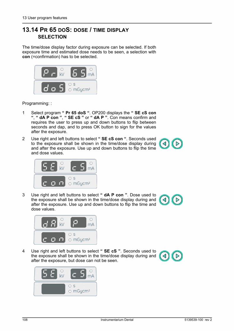
13 User program features
13.14 PR 65 DOS: DOSE / TIME DISPLAY SELECTION
The time/dose display factor during exposure can be selected. If bothexposure time and estimated dose needs to be seen, a selection withcon (=confirmation) has to be selected.
Programming: :
1 Select program “ Pr 65 doS “. OP200 displays the “ SE cS con“, “ dA P con ”, “ SE cS ” or “ dA P ”. Con means confirm andrequires the user to press up and down buttons to flip betweenseconds and dap, and to press OK button to sign for the valuesafter the exposure.
2 Use right and left buttons to select “ SE cS con “. Seconds usedto the exposure shall be shown in the time/dose display duringand after the exposure. Use up and down buttons to flip the timeand dose values.
3 Use right and left buttons to select “ dA P con ”. Dose used tothe exposure shall be shown in the time/dose display during andafter the exposure. Use up and down buttons to flip the time anddose values.
4 Use right and left buttons to select “ SE cS ”. Seconds used tothe exposure shall be shown in the time/dose display during andafter the exposure, but dose can not be seen.
108 Instrumentarium Dental 5139539-100 rev 2
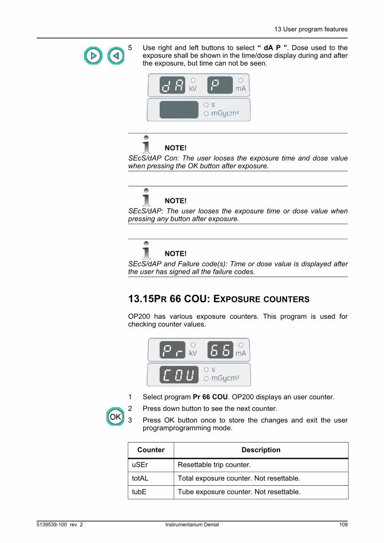
13 User program features
5 Use right and left buttons to select “ dA P ”. Dose used to theexposure shall be shown in the time/dose display during and afterthe exposure, but time can not be seen.
NOTE!
SEcS/dAP Con: The user looses the exposure time and dose valuewhen pressing the OK button after exposure.
NOTE!
SEcS/dAP: The user looses the exposure time or dose value whenpressing any button after exposure.
NOTE!
SEcS/dAP and Failure code(s): Time or dose value is displayed afterthe user has signed all the failure codes.
13.15PR 66 COU: EXPOSURE COUNTERS
OP200 has various exposure counters. This program is used forchecking counter values.
1 Select program Pr 66 COU. OP200 displays an user counter.
2 Press down button to see the next counter.
3 Press OK button once to store the changes and exit the userprogramprogramming mode.
Counter Description
uSEr Resettable trip counter.
totAL Total exposure counter. Not resettable.
tubE Tube exposure counter. Not resettable.
5139539-100 rev 2 Instrumentarium Dental 109

13 User program features
SErvicE Exposure count since last preventative maintenancereminder was resetted by Pr 59 PSE.
LEASE This counter is used only if the Sr 71 PAY leaseperiod has been activated.
InStALL This counter shows the number of exposures takenin the service mode only. When exposures are madein service mode, this doesn’t effect on user, serviceand lease counters.
Counter Description
110 Instrumentarium Dental 5139539-100 rev 2
14 User's statement
14User's statementInstructions for the use of the Orthopantomograph® OP200 andprecautionary statements are part of the OP200 User Manual.
Radiation leakage technique factors
The maximum-rated peak tube potential is 85 kV with the maximumrated continuous tube current of 1.5 mA. 1.5 mA is the equivalentmaximum rated continuous tube current for 13 mA with a duty cycle of1:7. Duty cycle is automatically calculated by the software so that thenext exposure does not exceed the anode thermal capacity. Theequation used by the software is
mA*s*kV = Initial heat capacity [J] + Anode cooling rate [J/s] * 3600 [s]
where:
mA*s*kV = Maximum energy input during one hour
Initial heat capacity = 28000 Joules [J] for tube type D-051S
Anode cooling rate = 120 Joules/s [J/s] for tube type D-051S
3600 = 1 hour observation time [s]
Beam limiting device / tube housing assembly compatibility
The tube housing assembly THA 100 is compatible with the beamlimiting device BDP138 or BDC184.
Equipment statement for tube housing assembly
Maximum operating voltage is 85 kV. Effective focal spot 0.5 (IEC 336/1982).
X-ray tube: Toshiba D-051S. For additional information please refer tothe tube specification sheets.
Maximum deviation from indicated values
Parameter Indicated value Deviation
Tube voltage 57 - 85 kV ± 5 kV
Tube current 2 - 16 mA ± 1 mA or 10%, whichever is larger
Exposure time (pan) 16.8 - 17.6 s ± 0.1 s or 10%, whichever is larger
Exposure time (TMJ, Sinus)
8 - 15.6 s ± 0.1 s or 10%, whichever is larger
Exposure time (cephalometric)
0.1 - 3.2 s
Exposure time (linear tomography)
1.6 - 28.8 s
5139539-100 rev 2 Instrumentarium Dental 111
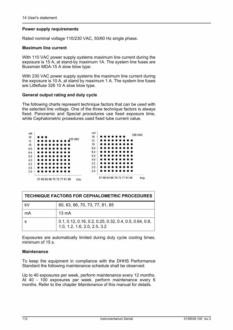
14 User's statement
Power supply requirements
Rated nominal voltage 110/230 VAC, 50/60 Hz single phase.
Maximum line current
With 110 VAC power supply systems maximum line current during theexposure is 15 A, at stand-by maximum 1A. The system line fuses areBussman MDA-15 A slow blow type.
With 230 VAC power supply systems the maximum line current duringthe exposure is 10 A, at stand by maximum 1 A. The system line fusesare Litfelfuse 326 10 A slow blow type.
General output rating and duty cycle
The following charts represent technique factors that can be used withthe selected line voltage. One of the three technique factors is alwaysfixed. Panoramic and Special procedures use fixed exposure time,while Cephalometric prosedures used fixed tube current value.
Exposures are automatically limited during duty cycle cooling times,minimum of 15 s.
Maintenance
To keep the equipment in compliance with the DHHS PerformanceStandard the following maintenance schedule shall be observed:
Up to 40 exposures per week, perform maintenance every 12 months.At 40 - 100 exposures per week, perform maintenance every 6months. Refer to the chapter Maintenance of this manual for details.
TECHNIQUE FACTORS FOR CEPHALOMETRIC PROCEDURES
kV 60, 63, 66, 70, 73, 77, 81, 85
mA 13 mA
s 0.1, 0.12, 0.16, 0.2, 0.25, 0.32, 0.4, 0.5, 0.64, 0.8, 1.0, 1.2, 1.6, 2.0, 2.5, 3.2
112 Instrumentarium Dental 5139539-100 rev 2

14 User's statement
Tube ratings
Maximum rating chart
Multi-Peak Full Wave rectified
(HF Inverter System)
Focal spot: 0.5 mm (IEC 336/1982)
Fig 14.1. Tube ratings
Tube anode thermal characteristics (D-051s)
Fig 14.2. Tube anode thermal characteristics (D-051S)
5139539-100 rev 2 Instrumentarium Dental 113

14 User's statement
Tube head assembly cooling curve
Fig 14.3. Tube head assembly cooling curve
We reserve the rights for technical changes at any time.
OP200/ OC200 Patient Dose
kV mA Patient doses, µSv in standard Panoramic program
number 1
57 2 1,9
63 5 5,7
63 10 10,9
63 13 12,8
66 5 7,2
66 13 16,8
66 16 21,0
70 5 8,6
70 13 20,4
70 16 26,5
73 8 15,5
73 13 23,8
73 16 31,7
77 5 12,1
77 8 18,7
77 13 27,1
114 Instrumentarium Dental 5139539-100 rev 2

14 User's statement
* Carpus imaging.
77 16 35,4
81 8 21,1
81 13 31,3
85 13 36,0
kV mA Times
Patient doses, µSv with cephalostat program
in lateral positioning (18x24cm)
*60 13 0,16 0,4
77 13 0,4 3,6
77 13 0,5 4,5
77 13 0,64 5,7
77 13 0,8 7,2
77 13 1,2 10,7
kV mA Patient doses, µSv in standard Panoramic program
number 1
5139539-100 rev 2 Instrumentarium Dental 115

14 User's statement
116 Instrumentarium Dental 5139539-100 rev 2
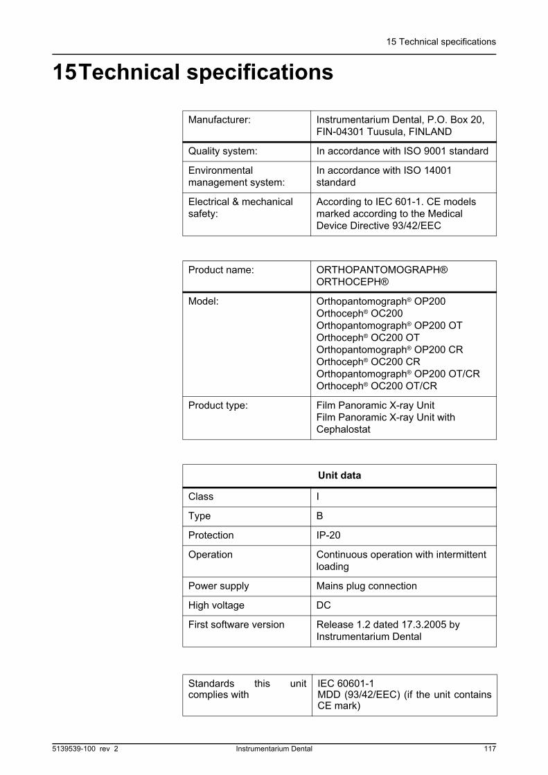
15 Technical specifications
15Technical specifications
Manufacturer: Instrumentarium Dental, P.O. Box 20, FIN-04301 Tuusula, FINLAND
Quality system: In accordance with ISO 9001 standard
Environmental management system:
In accordance with ISO 14001 standard
Electrical & mechanical safety:
According to IEC 601-1. CE models marked according to the Medical Device Directive 93/42/EEC
Product name: ORTHOPANTOMOGRAPH®ORTHOCEPH®
Model: Orthopantomograph® OP200Orthoceph® OC200Orthopantomograph® OP200 OTOrthoceph® OC200 OTOrthopantomograph® OP200 CROrthoceph® OC200 CROrthopantomograph® OP200 OT/CROrthoceph® OC200 OT/CR
Product type: Film Panoramic X-ray UnitFilm Panoramic X-ray Unit with Cephalostat
Unit data
Class I
Type B
Protection IP-20
Operation Continuous operation with intermittent loading
Power supply Mains plug connection
High voltage DC
First software version Release 1.2 dated 17.3.2005 by Instrumentarium Dental
Standards this unitcomplies with
IEC 60601-1MDD (93/42/EEC) (if the unit containsCE mark)
5139539-100 rev 2 Instrumentarium Dental 117

15 Technical specifications
Tube head assembly
Tube head assembly type THA 100
Tube type Toshiba D-051S, Stationary anode
Tube voltage 57-85 kV
Max. tube current 2-16 mA
Max. electric output 1,36 kW
Target angle 5 degrees
Focal spot 0,5 mm (IEC 336/1982)
Nominal anode input power
1750 W
Max. anode heat content 28 kJ
Max. X-ray tube assembly heat content
385 kJ
Max. continuous heat dissipation of the X-ray tube assembly
38W
Total filtration 2,5 mm Al
Additional filtration for Linear Tomography
12 mmAl
Leakage Technique Factors
85 kV / 1.5 mA
Electrical connections
Nominal mains voltage 110/230 VAC Automatic mains voltage compensation
Input power frequency 50 / 60 Hz
Nominal current 10A @ 230 VAC, 15A @ 110 VAC
Fuses 326 Littelfuse (slow blow) 10A @ 230 VAC, MDA-15 COOPER BUSSMAN (Time delay) 15A @ 110 VAC
Power consumption 2.3 kVA @ 230 VAC, 1.65 kVA @ 110 VAC
Maximum impedance of main
1,0
118 Instrumentarium Dental 5139539-100 rev 2

15 Technical specifications
X-ray Generator:
Nominal power 1.2 kW
Tube voltage 57 - 85 kV
Tube current 2-16 mA
Supply frequency 75 - 150 kHz
Spine compensation 0 to 2 mA steps increase, max. 16 mA
Spine compensation mode
Automatic (ASC), Pre-programmed
Digital Imaging Options:
CR model or CR kitAllows the use of (24 x 30 cm) cassette size in Pan cassette holder. (Especially if (24 x 30 cm) PSP plates are used)
OP200 CR, OC200 CR, OP200 OT/CR and OC200 OT/CR models for Panoramic, TMJ, Maxillary Sinus, Cephalometric and Linear Tomography Imaging
CCD Technique OP200 upgrade kit or OC200 upgrade kit.
Procedures:
Imaging programs: 5 Panoramic, 4 TMJ, Maxillary Sinus, 2 Linear Tomography and
CephalometricExposure Control: Automatic, Pre-programmed,
Manual and Quality Assurance
Panoramic and special imaging programs, exposure time, nominal magnification:
Standard (Program 1) 17.6 s 30%
Pediatric (P2) 16.8 s 30%
Ortho Zone (P3) 16.8 s 25%
Orthogonal (P4) 16.8 s 30%
Wide arch panoramic exposure (P5)
17.4 s 30%
5139539-100 rev 2 Instrumentarium Dental 119

15 Technical specifications
TMJ, lateral (P6) orOrtho TMJ, axial corrected lateral projection (P6 optional)
10.8 s
10.8 s
23%
TMJ jaw closed & open (P7) 15.6 s 23%
TMJ PA (P8) 8.0 s 80%
TMJ lateral & PA (P9) 12.2 s 23 & 80%
Maxillary sinus (P 10) 15.6 s 30%
Technique Factors, Cephalostat Procedures:
Tube voltage/Tube current /Exposure time (P11-P12)
60 - 85 kV, 8 values / 13 mA / 0.1 s - 3.2 s, 16 values
Magnification: 14% nominal in cephalometric procedures (adjustable 8-14%)
Exposure Time Limit: 22 s
Technique Factors, Linear Tomography Procedures:
Mandible (P13) & Maxillary (P14)
57 - 85 kV / 2 -16 mA / 1.6 - 28.8 s
Magnification: 40%
Linear Tomography Image Layers:
Choice of longitudinal images
3, 1 or none
Choice of transversal images
3, 1 or none
Positioning Lights:
Panoramic, TMJ & Maxillary Sinus Programs
laser (CLASS 1 LASER PRODUCT)
Linear Tomography Programs
laser (CLASS 1 LASER PRODUCT)
Panoramic and special imaging programs, exposure time, nominal magnification:
120 Instrumentarium Dental 5139539-100 rev 2

15 Technical specifications
Panoramic Film Cassette:
Film size 15 x 30 cm
Cassette type and screens
Flat cassette. Window for Ortho ID film marking. Kodak Ektavision intensifying screens, Kodak Lanex Regular or Kodak Lanex Medium.
Cephalostat Film Cassette(S):
Film sizes 18 x 24 cm and 24 x 30 cm8" x 10",10" x 12"
Cassette types and screens
Flat cassette(s). Window for Ortho ID film marking. Kodak Ektavision intensifying screens, Kodak Lanex Regular or Kodak Lanex Medium. Cassettes are optional on some market areas.
Optional Grid Cassette For Linear Tomography Procedures:
Film size 15 x 30 cm
Cassette type and screens
Flat cassette. Window for Ortho ID film marking. Grid ratio 6:1. Parallel focus. 57 lines / cm. Integrated or external grid. Kodak Ektavision intensifying screens, Kodak Lanex Regular or Kodak Lanex Medium.
Interfaces:
Exposure button Auxiliary button with 10 m cable for remote use (optional in USA/Canada)
Film marking Serial interface for Ortho ID
Panoramic patient positioning:
Operation Left or right side of the unitMotorized carriage movement
Positioning aids Chin rest, bite block, 3-point headrest, curved mirror, laser (CLASS I PRODUCT) positioning lights, occlusion correction buttons
5139539-100 rev 2 Instrumentarium Dental 121
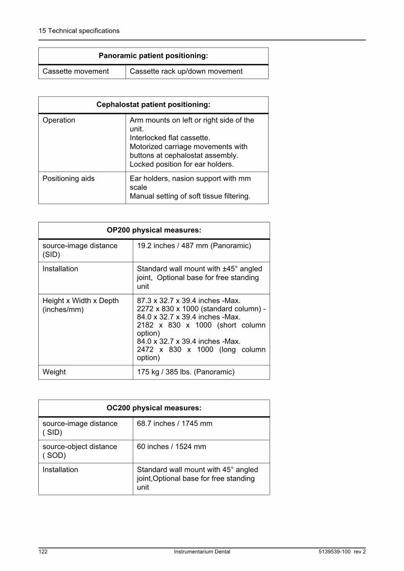
15 Technical specifications
Cassette movement Cassette rack up/down movement
Cephalostat patient positioning:
Operation Arm mounts on left or right side of the unit.Interlocked flat cassette.Motorized carriage movements with buttons at cephalostat assembly.Locked position for ear holders.
Positioning aids Ear holders, nasion support with mm scaleManual setting of soft tissue filtering.
OP200 physical measures:
source-image distance (SID)
19.2 inches / 487 mm (Panoramic)
Installation Standard wall mount with ±45° angled joint, Optional base for free standing unit
Height x Width x Depth (inches/mm)
87.3 x 32.7 x 39.4 inches -Max.2272 x 830 x 1000 (standard column) -84.0 x 32.7 x 39.4 inches -Max.2182 x 830 x 1000 (short columnoption)84.0 x 32.7 x 39.4 inches -Max.2472 x 830 x 1000 (long columnoption)
Weight 175 kg / 385 lbs. (Panoramic)
OC200 physical measures:
source-image distance( SID)
68.7 inches / 1745 mm
source-object distance ( SOD)
60 inches / 1524 mm
Installation Standard wall mount with 45° angled joint,Optional base for free standing unit
Panoramic patient positioning:
122 Instrumentarium Dental 5139539-100 rev 2

15 Technical specifications
15.1 ELECTROMAGNETIC COMPATIBILITY (EMC) TABLES
Height x Width x Depth (inches/mm)
87.6 x 74.8 x 39.4 inches-Max. 2272 x 1900 x 1000 (standardcolumn)-84.0 x 74.8 x 39.4 inches-Max. 2182 x 1900 x 1000 (short columnoption)84.0 x 32.7 x 39.4 inches -Max.2472 x 830 x 1000 (long columnoption)
Weight 210 kg / 465 lbs. (Cephalometric)
Ambient temperatures:
Transportation and Storage
-10°…+50°C
Operation Temperature +10°...+40°C, RH max. 95%
OC200 physical measures:
Orthopantomograph® OP200 is suitable for use in the specified electromagnetic environment.The purchaser or user of Orthopantomograph® OP200 should assure that it is used in anelectromagnetic environment as described below:
Emissions Test Compliance Electromagnetic Environment
Radio-FrequencyEmissionsCISPR11
Group 1 Orthopantomograph® OP200 uses RF energy only for its internal function. Therefore, the RF emission is very low and not likely to cause any interference in nearby electronic equipment.
Radio-FrequencyEmissionsCISPR11
Class B Orthopantomograph® OP200 is suitable for use in all establishments, including domestic establishments and those directly connected to the public low-voltage power supply network that supplies buildings used for domestic purposes.
Harmonic emissions
IEC 61000-3-2
IEC 61000-3-2 Class A
Orthopantomograph® OP200 is suitable for use in all establishments, including domestic establishments and those directly connected to the public low-voltage power supply network that supplies buildings used for domestic purposes.
Voltage fluctuations/
flicker emissions
IEC 61000-3-3
Complies Orthopantomograph® OP200 is suitable for use in all establishments, including domestic establishments and those directly connected to the public low-voltage power supply network that supplies buildings used for domestic purposes.
Table 15.1 Electromagnetic emissions IEC 60601-1-2 Ed2
5139539-100 rev 2 Instrumentarium Dental 123
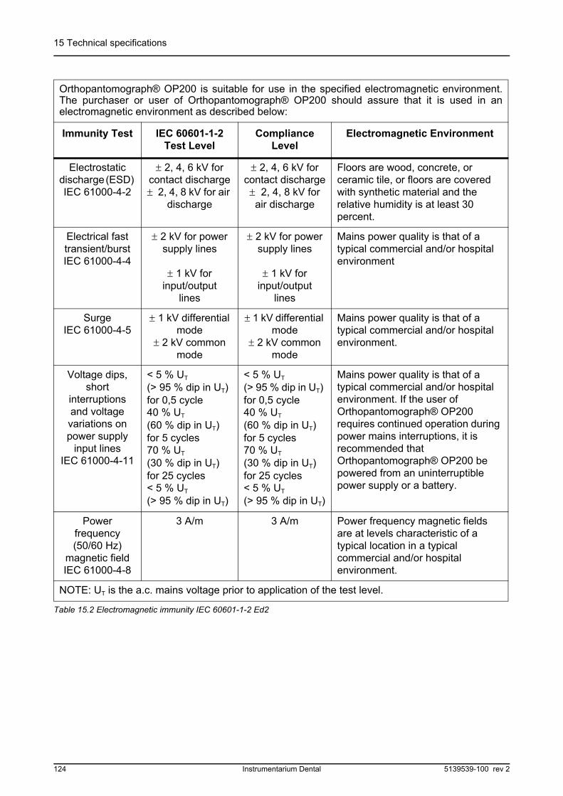
15 Technical specifications
Orthopantomograph® OP200 is suitable for use in the specified electromagnetic environment.The purchaser or user of Orthopantomograph® OP200 should assure that it is used in anelectromagnetic environment as described below:
Immunity Test IEC 60601-1-2Test Level
ComplianceLevel
Electromagnetic Environment
Electrostatic discharge (ESD) IEC 61000-4-2
2, 4, 6 kV for contact discharge 2, 4, 8 kV for air
discharge
2, 4, 6 kV for contact discharge 2, 4, 8 kV for air discharge
Floors are wood, concrete, or ceramic tile, or floors are covered with synthetic material and the relative humidity is at least 30 percent.
Electrical fast transient/burstIEC 61000-4-4
2 kV for power supply lines
1 kV for input/output
lines
2 kV for power supply lines
1 kV for input/output
lines
Mains power quality is that of a typical commercial and/or hospital environment
SurgeIEC 61000-4-5
1 kV differential mode
2 kV common mode
1 kV differential mode
2 kV common mode
Mains power quality is that of a typical commercial and/or hospital environment.
Voltage dips, short
interruptions and voltage variations on power supply
input linesIEC 61000-4-11
< 5 % UT
(> 95 % dip in UT) for 0,5 cycle40 % UT
(60 % dip in UT) for 5 cycles70 % UT
(30 % dip in UT) for 25 cycles< 5 % UT
(> 95 % dip in UT)
< 5 % UT
(> 95 % dip in UT) for 0,5 cycle40 % UT
(60 % dip in UT) for 5 cycles70 % UT
(30 % dip in UT) for 25 cycles< 5 % UT
(> 95 % dip in UT)
Mains power quality is that of a typical commercial and/or hospital environment. If the user of Orthopantomograph® OP200 requires continued operation during power mains interruptions, it is recommended that Orthopantomograph® OP200 be powered from an uninterruptible power supply or a battery.
Power frequency(50/60 Hz)
magnetic fieldIEC 61000-4-8
3 A/m 3 A/m Power frequency magnetic fields are at levels characteristic of a typical location in a typical commercial and/or hospital environment.
NOTE: UT is the a.c. mains voltage prior to application of the test level.
Table 15.2 Electromagnetic immunity IEC 60601-1-2 Ed2
124 Instrumentarium Dental 5139539-100 rev 2

15 Technical specifications
Orthopantomograph® OP200 is suitable for use in the specified electromagnetic environment.The purchaser or user of Orthopantomograph® OP200 should assure that it is used in anelectromagnetic environment as described below:
ImmunityTest
IEC60601-1-2Test Level
ComplianceLevel
ElectromagneticEnvironment
Conducted RF IEC
61000-4-6
Radiated RFIEC
61000-4-3
3 V150 kHz to80 MHz
3 V/m80 MHz to2,5
GHz
[ V1 ] 3 V
[ E1 ] 3 V/m
Portable and mobile RF communications equipment are used no closer to any part of Orthopantomograph® OP200, including cables, than the recommended separation distance calculated from the equation appropriate for the frequency of the transmitter.
Recommended Separation Distance:
80 MHz to 800 MHz
800 MHz to 2,5 GHz
Where P is the maximum output power rating of the transmitter in watts (W) according to the transmitter manufacturer and d is the recommended separation distance in meters (m).Field strengths from fixed RF transmitters, as determined by an electromagnetic site survey,* are less than the compliance level in each frequency range.** Interference may occur in the vicinity of equipment marked with the following symbol:
*Field strengths from fixed transmitters, such as base stations for cellular telephones and landmobile radios, amateur radio, AM and FM radio broadcast, and TV broadcast cannot beestimated accurately. To assess the electromagnetic environment due to fixed RF transmitters,an electromagnetic site survey should be performed. If the measured field strength exceeds theRF compliance level above, observe Orthopantomograph® OP200 to verify normal operation ineach use location. If abnormal performance is observed, additional measures may be necessary,such as re-orienting or relocating Orthopantomograph® OP200.**Over the frequency range 150 kHz to 80 MHz, field strengths are less than [V1] V/m.
The Recommended Separation Distances are listed in the next table.Note: These guidelines may not apply in all situations. Electromagnetic propagation is affectedby absorption and reflection from structures, objects, and people.
Table 15.3 RF immunity of non-life-support equipment or system IEC 60601-1-2
PV
= d ]5,3
[1
PE
= d ]5,3
[1
PE
= d ]7
[1
5139539-100 rev 2 Instrumentarium Dental 125

15 Technical specifications
126 Instrumentarium Dental 5139539-100 rev 2
16 Maintenance
16MaintenanceThis unit is designed to provide reliable performance and many yearsof customer satisfaction. In order to assure safe performance of this X-ray equipment, a preventative maintenance program must beestablished. It is the owner's responsibility to supply or arrange for thisservice. Consult your Orthopantomograph® dealer to arrange for thisservice.
16.1 MAINTENANCE SCHEDULE
Maintenance service for Orthopantomograph® OP200 is suggested atinstallation and after each 2000 exposures. This periodic maintenanceis outlined in OP200 Service Manual Maintenance.
These maintenance procedures require the services of a qualifiedtechnician. In addition to periodic maintenance any deviation fromnormal performance should be immediately reported to your dealer.
WARNING!
Only trained and qualified personnel should be permitted access to theinternal parts of the equipment.
16.2 MONTHLY INSPECTION BY USER
The user must perform monthly the following inspections:
– Visually check that all visible labels are intact and legible– Visually check that the exposure indicator light is lit for the
duration of exposure– Confirm that the audible indicator sounds for the duration of the
exposure– Check that exposure button must be kept pressed continuously
during the exposure cycle– Check that exposure terminates and an error code is displayed
when prematurely releasing the exposure button– Check all the functions of the control panel and the positioning
panel
16.3 PREVENTATIVE MAINTENANCE REMINDER
The equipment has a special feature that displays a message "Ch 8PSE" on time display after every 2000 exposures. See User programchapter in OP200 User Manual for details.
NOTE!
Wiring diagrams, schematics and other documents, which are neededwhen the unit is repaired, will be supplied by request to authorizedservice personnel.
5139539-100 rev 2 Instrumentarium Dental 127

16 Maintenance
128 Instrumentarium Dental 5139539-100 rev 2