Embed Size (px)
Citation preview

INTERNAL SIREN WARNINGThe Enforcer 32-WE control
panel contains a 100 dBA siren, please be aware of
this when in use.
User Manual
RINS1503-2Software Revision >V9.26

2
Contents Page
A: Introduction 3B: Keypads / Readers 4C: Using the Keyfob 5D: Arming the Enforcer 6E: Disarming the Enforcer 7F: Arming / disarming with the tag reader 8G: Open doors / Arm and Disarm (Entry Control) 8H: SMS Commands (GSM V9.2 or above only) 9H: SMS Commands (GSM version only) - Continued... 10I: Pyronix SMS Control Mobile Phone Application 12J: Chime Feature 13K: Personal Attack From Keypad 13L: Fire Alarm From Keypad 13M: Master Manager Menu Options 14N: Entering the Master Manager Menu 15 1 Master Manager Menu: Bypass Inputs 15 2 Master Manager Menu: Operate User Automation Outputs 15 3MasterManagerMenu:ConfigureDate&Time* 16 4MasterManagerMenu:ChangeCodes(Configureusercodes,learntagsandkeyfobs)* 17 5 Master Manager Menu: Review Logs (Event memory logs) 20 6 Master Manager Menu: SMS Phonebook 21 7MasterManagerMenu:WalkTest 21 8MasterManagerMenu:BellTest 21 9 Master Manager Menu: PC Connect Menu 22 10 Master Manager Menu: Allow Engineer Menu 22 11 Master Manager Menu: Block Remote Arm 23 12 Master Manager Menu: Block UDL 23 13 Master Manager Menu: Exit Master Menu 24O:EngineerContactsandTable 25P:InputTables 26Q:UserTables 28R: Outputs 29S: Product Information 30T:Notes 31* To quick start the system, only these features are needed to be programmed.

3
A: Introduction
Two Way Wireless High SecurityTheEnforcer32-WEisawirelessalarmsystemthathasbeendesignedwithyoursecurityinmind;withquickandeasyinstallationandminimalmaintenance,theEnforcer32-WEprotectsyourhomewithamultitudeofuniquefeatures.
TakingfulladvantageofPyronix’sinnovativetwowaywirelesstechnology,thewirelessdevicesontheEnforcer32-WEsystemareconstantlycommunicatingwitheachother,usingthePyronixHighSecurityWirelessEncryptionProtocol.
TheEnforcer32-WEtwowaywirelessdevicesarefullyoperationalwhenthesystemisarmed,makingyoursystemmoresecure,comparedtootherwirelesssystems,wheredevicesaredisabledforuptofiveminutesaftereveryactivationtosavebattery,thereforecompromisingyoursecurity.
TheEnforcer32-WEhasbeenengineeredbyPyronixasasecure,reliableandeasytousewirelessalarmsystem.Itincludesthefollowingfeatures:
Battery Monitoring/SavingTheEnforcer32-WEsystemusesadvancedtechnologytopreservethebatterylifeofeachwirelessdevice.However,theEnforcer32-WEinformsyouwhenabatteryneedsreplacingamonthinadvancebeforethedevicestopsworking.Thiskeyfeaturegivesyouenoughtimetochangethebatteryinthespecificdevice.Otherwirelessalarmsystemsmaynotgiveyoualowbatterywarningsignal,meaningthatdevicescouldstopworking,leavingyourenvironment unprotected.
High Security Encryption 128bithighsecuritywirelessencryptionprotocol,andintelligentwirelessjammingdetection.
User Friendly KeyfobsThefullytwowaywirelesskeyfoballowsyoutoseethestatusofthecontrolunitvia3colourLEDs:System armed: When the system is armed a RED LED will illuminate momentarilySystem disarmed: When the system is disarmed a GREEN LED will illuminate momentarilySystem fault:WhenthesystemisinfaultconditionanAMBERLEDwillilluminatemomentarily,Thiswillalsoflashwhenthekeyfobisunabletoarmthesystem. Itispossibletoallocatedifferentfunctionstoeachkeyfobsuchasarming/disarmingdifferentareas,activatingoutputstocontrolexternaldevicessuchasgates,requestingsystemstatus,andactivatingpanicalarms.Upto32wirelesskeyfobscanbeaddedtotheEnforcer32-WEsystem.Eachwirelesskeyfob has its own user ID which can be reported to the ARC and user mobile phone which are stored into the event log of the control panel individually. Thekeyfobalsoallowsyoutoarm/disarmeveryareaindividually,givingyoutotalcontrolofyoursystem.
User Automation OutputsTheEnforcer32-WEincludesuserautomationoutputsthatgiveyoutheoptiontooperateupto20devicessuchasgates,lights,sprinklers,etc.viayourkeypadorremotelyviayourKeyfob,extendingtheuseofyoursecuritysystem.
SMS Text Notifications and Remote ControlThesystemwillnotifyyouviaSMStextmessagesinrealtime.Forexamplenotificationthatyourchildhasreturnedhomefromschoolsafelyornotificationofaleakageofwaterinyourpropertyetc.
4
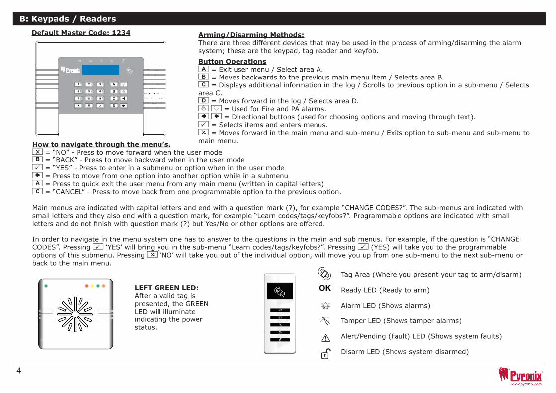
B: Keypads / Readers
Arming/Disarming Methods:Therearethreedifferentdevicesthatmaybeusedintheprocessofarming/disarmingthealarmsystem;thesearethekeypad,tagreaderandkeyfob.
Default Master Code: 1234
Button Operationsa = Exit user menu / Select area A.b = Moves backwards to the previous main menu item / Selects area B.c = Displays additional information in the log / Scrolls to previous option in a sub-menu / Selects area C.D = Moves forward in the log / Selects area D.f p = Used for Fire and PA alarms.[ ] = Directional buttons (used for choosing options and moving through text).t = Selects items and enters menus.x = Moves forward in the main menu and sub-menu / Exits option to sub-menu and sub-menu to main menu.
TagArea(Whereyoupresentyourtagtoarm/disarm)
Ready LED (Ready to arm)
Alarm LED (Shows alarms)
TamperLED(Showstamperalarms)
Alert/Pending (Fault) LED (Shows system faults)
Disarm LED (Shows system disarmed)
LEFT GREEN LED: After a valid tag is presented,theGREENLED will illuminate indicating the power status.
Page: 5
C H A P T E R 2 : K E Y P A D S / R E A D E R S
There are four different devices that may be used to arm/disarm the alarm system; these arethe main keypad, the external tag reader, internal tag reader and the keyfob.
Control Panel Keypad a = Quick exit manager menu. b = Moves backwards to the previous menu item.c = Enables chime and displays additional information in the log.D = Moves forward in the log, scrolls between options and enters the master manager menu.
fp = Used to activate FIRe/PA alarms.
[] = Directional buttons.
t = Selects items and enters menus.
x = Cancels items, and moves to the nextitem in master manager menu .
The Internal Tag Reader Tag Area (Where you present your tag to arm/Unset)
Ready LED
Alarm LED
Tamper LED
Fault LED
Disarmed LED
The External Tag Reader
LEFT GREEN LED: Status indicator (extinguishes after a couple of seconds)
RED LED: This can be programmed by your engineer to illuminate when the alarm has activated for example.
How to navigate through the menu’s.x = “NO” - Press to move forward when the user mode b = “BACK” - Press to move backward when in the user modet = “YES” - Press to enter in a submenu or option when in the user mode] = Press to move from one option into another option while in a submenua=Presstoquickexittheusermenufromanymainmenu(writtenincapitalletters)c = “CANCEL” - Press to move back from one programmable option to the previous option.
Mainmenusareindicatedwithcapitallettersandendwithaquestionmark(?),forexample“CHANGECODES?”.Thesub-menusareindicatedwithsmalllettersandtheyalsoendwithaquestionmark,forexample“Learncodes/tags/keyfobs?”.Programmableoptionsareindicatedwithsmalllettersanddonotfinishwithquestionmark(?)butYes/Noorotheroptionsareoffered.
Inordertonavigateinthemenusystemonehastoanswertothequestionsinthemainandsubmenus.Forexample,ifthequestionis“CHANGECODES”. Pressing t‘YES’willbringyouinthesub-menu“Learncodes/tags/keyfobs?”.Pressingt (YES) will take you to the programmable options of this submenu. Pressing x‘NO’willtakeyououtoftheindividualoption,willmoveyouupfromonesub-menutothenextsub-menuorback to the main menu.

5
C: Using the Keyfob
Thewirelesskeyfobhasfourbuttonsthatmaybeprogrammedforspecificfunctions:noaction,showstatus,armarea,disarmarea,latchoutput,timedoutputandPAalarmactivation.
Locking the KeyfobAllfourbuttonsonthekeyfobmaybe‘locked’topreventfromauseraccidentallypressingthem.
Locking the keys on the keyfob is performed by pressing any buttons that are diagonal with one another at the same time(LOCK&IIorUNLOCK&I).
TheREDLEDwillflashindicatingthatthefobhasbeenlocked.
Tounlock,pressbothbuttonstogetheragainandtheGREENLEDwillflashindicatingthatthekeyfobisnow unlocked.
NOTE: When the keyfob is locked, all indications are also disabled.
ButtonsThebuttonscanbecustomisedtooperateasdesired(programmedinthefunction‘ChangeCodes’).Belowareexamplesonhoweachbuttoncanbeprogrammed: BUTTON = Programmedfor‘ArmArea’Whenpressed,oneormoreareaswillbearmed BUTTON=Programmedfor‘DisarmArea’.Whenpressed,oneormoreareaswilldisarmed.I BUTTON =Programmedfor‘UserOutput’.Forexamplewhenpressed,agatecanbeopened.Whenpressedagain,agatecanbeclosed.II BUTTON=Programmedfor‘‘StatusLED’.Forexamplewhenpressed,thesystemstatusisshown’RED=Armed,GREEN=Disarmed,AMBER=Fault.
Quick ArmingIfoneofthebuttonsisprogrammedas‘ArmArea’,thealarmsystemcanbearmedbythekeyfob.Thekeypadwillthenstarttocountdowntheexittime(dependingwhattheexitmodeisprogrammedbytheengineer).Oncethealarmpanelisinthis‘arming’stage,itispossibleto‘quickarm’thesystembypressingthesamebuttonagain;thiswillreducethetimeofarmingandthereforemakingthesystemarmimmediately.ThedisarmLEDon the keypad will turn off and a beep will be heard once the system has been armed and the RED LED on the keyfob will be illuminated for a short time.
Page: 8
C H A P T E R 5 : S E T T I N G T H E A L A R M ( C O D E / T A G )
Enter your user code
Or
Present a valid tag
Enter the level set you wish to set, and press the I key
‘Please wait arming wireless’ will be displayed
There are three different setting methods your installer will instruct you through which of these has been designed into your system.
Final Door: Leave the building and make sure the exit door is closed properly
Timed: Make sure you leave the building before the timer shown on the keypad expires
Push to set: Press the push to set button installed by your engineer to arm the system
SETTING USING A WIRELESS KEY-FOB
To set via a key-fob. Press the key
The key-fob LED will start to flash GREEN indicating that the system is starting to set
‘Please wait arming wireless’ will be displayed on the keypad and the programmed area will begin to set.
To ‘quick set’, press the key again.
Once set, the key-fob LED will illuminate RED indicating that the system is now set

6
D: Arming the Enforcer
Page: 8
C H A P T E R 5 : S E T T I N G T H E A L A R M ( C O D E / T A G )
SETTING USING A WIRELESS KEY-FOB
To set via a key-fob. Press the key
The key-fob LED will start to flash GREEN indicating that the system is starting to set
‘Please wait arming wireless’ will be displayed on the keypad and the programmed area will begin to set.
To ‘quick set’, press the key again.
Once set, the key-fob LED will illuminate RED indicating that the system is now set
Enter your code and deselect any area’s that are not to be armed*.
*This will only be possible if “Arm Area Choice” is selected as ‘Yes’ in the function “Learn User Codes/Tags/Keyfobs. If selected as “No” then all areas allocated to the user code will arm.
**The keyfob buttons can be programmed in the function “Learn User Codes/Tags/Keyfobs”.
Present your tag and deselect any area’s that are not to be armed*.
Press the arming button on the keyfob**.1 2 3
Enforcer 32WE
Time 02:53
c
Enter Your
Code
[******]
Arm Areas
[ABCD]Please
Wait
Arming Wireless
tArming
[029]
Area A
UserCode
t
Stop Arming?
[******]
UserCode
Stop Arming?
[ABCD]
t
Deselect the Area'snot needed to be armed
t

7
Page: 8
C H A P T E R 5 : S E T T I N G T H E A L A R M ( C O D E / T A G )
SETTING USING A WIRELESS KEY-FOB
To set via a key-fob. Press the key
The key-fob LED will start to flash GREEN indicating that the system is starting to set
‘Please wait arming wireless’ will be displayed on the keypad and the programmed area will begin to set.
To ‘quick set’, press the key again.
Once set, the key-fob LED will illuminate RED indicating that the system is now set
*This will only be possible if “Arm Area Choice” is selected as ‘Yes’ in the function “Learn User Codes/Tags/Keyfobs. If selected as “No” then all areas allocated to the user code will disarm.
**The keyfob buttons can be programmed in the function “Learn User Codes/Tags/Keyfobs”.
Press the arming button on the keyfob**.1 2 3
Enforcer 32WE
Arm Area
A
Enter Your
Code
[******]
Disarm Areas
[ABCD]Enforcer
32WE
Time 02:53
c
tUserCode
t
Deselect the Area'sto be disarmed
E: Disarming the Enforcer
Enter your code and deselect any area’s that are not to be disarmed*.
Enter your code and deselect any area’s that are not to be disarmed*.

8
F: Arming / disarming with the tag reader
G: Open doors / Arm and Disarm (Entry Control)
Ifyouhaveatagreaderinstalled,thenitwillbepossibletoarmanddisarmthealarmsystemusingatag.
A tag reader can also be used to unlock entry doors.
External Tag Reader Instructions:
Arming:Presentavalidtagtothereader,theGREENLEDwillilluminateontheexternalreader,removethetag,thedoorwillunlock,thenpresentthesame tag within 10 seconds and the system will arm and the door will lock.
Disarming:Presentavalidtagtothereaderandthenremoveit,thestatuswillbeshown(thealarmsymbolwillilluminateindicatingthesystemisarmedontheinternalreaderandtheREDLEDontheexternalreader),presentthesametagwihthin10secondsagainandthesystemwillbedisarmed,and the door will unlock.
Access Control/Entry Control:Thereaderscanbeusedalsoforopeningdoorsonlywithouttheabilitytoarmanddisarm.Pleasecontactyourinstallerfor more information on this feature.
Disarmed Locked Armed
Disarmed Armed
Disarmed Armed
NOTE:IftheEnforcerhasfailedtoset,afaultwillbedisplayedontheinternaltagreader or a fail to set sound will activate on the external tag reader buzzer.
NOTE:IftheEnforcerhasfailedtoset,afaultwillbedisplayedontheinternaltagreader or a fail to set sound will activate on the external tag reader buzzer.
Disarmed Locked Armed

9
H: SMS Commands (GSM V9.2 or above only)
IfyouhavepurchasedtheGSMversionofEnforcer,itwillallowyoutosendSMScommandsviaamobilephonetobeabletoarm/disarmthepanelremotely and others. See below the different SMS commands available.NOTE:AnytextmessagecommandtotheEnforcerwillneedtostartwithavalidusercode.NOTE:Textmessagescommandsarenotcasesensitiveexceptwhentheusedoutputsareactivated.NOTE:IfatextmessagescommandsisnotrecognisedbyEnforceritwillsendbacktotheuserthewrongcommand.
Arming via SMS text command
Example SMS command send: Description: Example SMS command response:
123456 Arm A 123456 = User Code. Arm A = Will arm the Enforcer in Area A. FinalArm;AreaA
123456 Arm ABCD 123456 = User Code. Arm ABCD = Will arm the Enforcer in Area ABCD. FinalArm;AreaABCD
NOTE: If no areas are specified then all areas will arm (default). In ‘One Area’ Mode, the default will be Area A.
Disarming via SMS text command
Example SMS command send: Description: Example SMS command response:
123456 Disarm A 123456 = User Code. Disarm A = Will disarm Area A. Disarm;AreaA
123456 Disarm ABCD 123456 = User Code. Disarm ABCD = Will disarm the Area ABCD. Disarm;AreaABCD
NOTE: If no areas are specified then all areas will disarm (default). In ‘One Area’ mode, the default will be Area A.
Arming with inputs bypassed via SMS text command
Example SMS command send: Description: Example SMS command response:
123456 Arm A Bypass 4 123456 = User Code. Arm A Bypass 4 = Arms Area A and will bypass input number 4.
InputBypass;AreaAInput04Force Arm: Area A
123456 Arm A Bypass Kitchen 123456 = User Code. Arm A Bypass Kitchen = Arms Area A and will bypass the input that is called Kitchen.
InputBypass;AreaAKitchenForce Arm: Area A
Bypassing inputs via SMS text command
Example SMS command send: Description: Example SMS command response:
123456 Bypass 6 123456=UserCode.Bypass6=Inthenextarmingprocedure,inputnumber 6 will be bypassed.
InputBypass;AreaAInput06
123456 Bypass Garage 123456=UserCode.BypassGarage=Inthenextarmingprocedure,theinput called Garage will be bypassed.
InputBypass;AreaAGarage
NOTE: The name of the output has to be one word and spelled exactly as written in the panel. For example, Garage Door is not acceptable. It has to be written as Garage-Door in the panel and the respective command will be Garage-Door.

10
H: SMS Commands (GSM version only) - Continued...
Checking the System Status via SMS text command
Example SMS command send: Description: Example SMS command response:
123456 Status 123456 = User Code. Status Area A Disarmed No Faults
Area B Disarmed No Faults
Area C Disarmed No Faults
Area D Disarmed No Faults
Operating the User Automation Outputs via SMS text commands
Example SMS command send: Description: Example SMS command response:
123456 Output 1 On 123456 = User Code. User Output 1 turns on. OUTPUT1ON
123456 Output Garage-Door On 123456=UserCodeoutputGarage-Dooron=TurnsoutputnamedasGarage-Door on.
OUTPUTGarage-DoorON
123456 Output Garage-Door Off 123456=UserCodeoutputGarage-Dooroff=TurnsoutputnamedasGarage-Door off.
OUTPUTGarage-DoorOFF
NOTE: The user automation outputs can be also activated via the keypad or the keyfob. NOTE: The name of the output has to be one word and spelled exactly as written in the panel. For example, Garage Door is not acceptable. It has to be written as Garage-Door in the panel and the respective command will be Garage-Door.
Changing a Mobile Number via SMS text commands
Example SMS command send: Description: Example SMS command response:
123456 Change 07777888999 07878888999
123456 = User Code. Change number 07777888999 to number 07878888999
CHANGE 07878888999
Checking the User Automation Outputs status via SMS text commands
Example SMS command send: Description: Example SMS command response:
123456 Output 1 Status 123456 = User Code. User Output 1 status check. OUTPUTONorOUPUTOFF
123456 Output Garage-Door Status
123456 = User Code. Output Garage-Door status check. OUTPUTGarage-DoorONorOUTPUTGarage-Door OFF
NOTE: The name of the output has to be one word and spelled exactly as written in the panel. For example, Garage Door is not acceptable. It has to be written as Garage-Door in the panel and the respective command will be Garage-Door.
Start Uploading/Downloading via SMS text command
Example SMS command send: Description: Example SMS command response:
123456 UDL 123456=UserCode.UDL=TheEnforcerwillmakeanoutgoingdataconnection to the programmed PC1 number.
No response as the panel is already connected to the PC1
9999 UDL 9999=EngineerCodeUDL=TheEnforcerwillmakeanoutgoingdataconnection to the programmed PC1 number.
NO Response as the panel is already connected to the PC1

11
I: Pyronix SMS Control Mobile Phone Application
Thereisamobilephoneapplication(Androidonly)thatisavailabletodownloadviaourwebsiteandwillcontrolcertainaspectsofyourcontrolpanelfromyour mobile phone.
1) Download the Pyronix SMS control application from http://www.pyronix.com/pyronix-downloads.php
2) Install the application on your mobile phone (making sure “download from unknown sources” is enabled in your security settings).
3)Opentheapplication,itwillthenbeinstalledonyourphoneautomatically.
4)Theicontotheleftwillbedisplayedonyourphonemenu.Presstheicon.
5)Oncethestartupscreenhasloaded,youwillseethreeicons:ArmAreaA,DisarmAreaAandPanelStatus.Thesearethedefaultoperations.
6)Press‘Settings’andenterallyourpanelinformationsuchaspanelname,(yourengineerwillknowwhatthisis),panelinputnames(ifyouwishtoenteryourzonenamesonhere).Youcanalsochoosetheapplicationlanguageandapasswordforsecurity.NOTE:Itisrecommended that a password is entered so only you will have access to arming/disarming your control panel etc.
7)Press‘Command’tochoosedifferentoperationstothePCXcontrolpanelthatyouwishtooperate.Press‘AddCommand’-atdefault“Arm”willbeselected,pressthedropdownboxtoviewallotheroperationsthatarepossible:Arming,disarming,armwithbypass,bypasszones,controluseroutput,outputstatusandsystemstatus.Youmayalsochooseyourowniconstyleaswellsothedifferentcommandscanbeeasilyidentified.Onceallchangeshavebeenmadepress‘SAVE’andclickback.
8) All icons and commands will the be displayed on your home screen which can then be pressed and operated.
Screenshots

12
Page: 15
C H A P T E R 1 2 : A D V A N C E D F U N C T I O N S
12.1 Chime Feature
12.2 Omitting Inputs
12.3 Keypad Hold Up
If an emergency alarm is needed, press and hold both the 1 and 7 keys.
A ‘hold up’ alarm will be generated.
Note: The Hold Up facility needs to be enabled by your engineer (either silent or full alarm)
2-Key HU and any duress codes programmed on the system by your engineer are not permitted to send a signal to the Alarm Receiving Centre under police regulations in England, Wales or Northern Ireland
Please note that the key-fob can also be programmed to support a hold up alarm. Please discuss this with your engineer.
Thechimefeaturecanbeusedondoorcontactstoenablea‘chime’soundwhenadoor(input)isopened.Thisfeaturecan be set up by your installer.
Todisablethechimeonthekeypad,closealldoorsandwhen‘c’isdisplayed,press the ckey,acapital‘C’willbedisplayed,thiswillthenactivatethechime on any additional keypads with extension speakers installed. If you wish to disable the chime altogether press the c key again.
NOTE: Chime should not be used on motion detectors as this will drain the battery.
IfanPAalarmisneeded,pressandholdboth the 1 and 7 keys or hold p for3secondsanda‘PA’alarmwillbegenerated.
Note:ThePAfacilityneedstobeenabledby your engineer (either silent or full alarm)
Please note that the key-fob can also be programmed to support a PA alarm.
Please discuss this with your engineer.
Ifafirealarmisneeded,pressandholdffor3secondsanda‘fire’alarmwillbegenerated.
Note:TheFirealarmkeyneedtobeenabled by your engineer.
J: Chime Feature K: Personal Attack From Keypad L: Fire Alarm From Keypad

13
NOTE 1: Pressing the A key will exit the master manager menu at any main menu option above.
NOTE 2: Make sure you change the default master user code.
*ThesefeaturesareneededtoquicklysetuptheEnforcer.
M: Master Manager Menu Options
Bypass Inputs Disablesanysensor(input)onthesystemforthecurrentarmingperiod.Thisfeaturealsodisablestamperalarms.
Operate User Outputs Activates/deactivatesuserautomationoutputsthatareusedtoactivateremotelythedevicessuchaselectronicgates,lightsetc.
*Date & Time Programmesthedateandtimeandenablesthesummertimeautomaticadjustment.
*Learn User Codes, Keyfobs and Tags
Programmestheusercodes,tagsandlearnskeyfobstotheEnforcer32-WE.
Review Log The‘ReviewLogs’functionisusedtoviewalloperationalinformationofthealarmsystem,suchasarming/disarminginformation,accesscontrolandalarmactivationsetc.
SMS Phonebook IfSMStextingisenabled,therewillbeupto4mobilenumbersthatcanbeprogrammedtosendSMSalarms.Pleasediscussthisfeaturewithyourinstallerifrequired.
Walk Test The‘WalkTest’functionallowsthetestingofallprogrammedinputsonthealarmsystem.
Bell Test Thisfunctionisusedtoteststheexternalsiren(wiredandwireless)andstrobe.
PC Connect Menu Thecontrolpanelmaybedialledinto,andprogramminginformationkeptonaPCusingtheInSiteUDLsoftware.ThisfunctionallowsthecontrolpaneltodialaPre-programmedPCtelephonenumber(programmedbyyourengineer).Thisisusually used by your engineer during a maintenance call.
Allow Engineer Menu Ifthisfunctionisenabled,theengineerwillrequireauthorisationfromyoubeforetheycanaccesstheengineermenu.
Block Remote Arming Blocks any attempt at arming the system remotely via the upload/download software
Block UDL Blocks any attempt at dialling into the system remotely via the upload/download software
Exit Manager Mode Exits the Manager Mode

14
Default Master User Code: 1234
BYPASS INPUTS? Bypass
Input[--]
OPERATE USER
OUTPUTS?
t
x
Bypass Input[--]
Input 01
t
Choose an
Input:
01 to
66
x x
b
OPERATE USER
OUTPUTS?Select
Output
[01]
DATE & TIME?
t
x
Output Off
tOutput
On
t
b
Select User
Automation
Output:
[01] Output
1
-[30]
Output
30
Show Current
Ouput
Status
Turn Ouput
On
/ Off
t
x xx
1 Master Manager Menu: Bypass Inputs
2 Master Manager Menu: Operate User Automation Outputs
Enforcer 32WE
Time 02:53
c
Enter Your
Code
[****]
BYPASS INPUTS?
D t
N: Entering the Master Manager Menu

15
Default Master User Code: 1234
3 Master Manager Menu: Configure Date & Time*
DATE & TIME? Year
(00-99 )
[07]
Month (1-12 )
[01]
Day (1-31 )
[01]
Hours (0-23 )
[23]
Options:[0]
No
[1] Yes
Summer Time
Adj?
No
[0]
Minutes (0-59 )
[31]
CHANGE CODES?
x
t t t
x x x
x
t
b
t t t
x x

16
LEARN USER
CODES
KEYFOBS & TAGS?
User Codes/Tags/
Learn Keyfobs?
Empty
[01] Enter User
Code
[
]
Change Master
Manager Code?
Master Manager
Code
[******]
t
x
User Type
User
[0]User
In
Area
[ABCD]
User Type:
[0] User
[1] Manager
User Arm
Options
Disarm/Arm
[0]
User Arm
Options:
[0] Disarm/Arm
[1] Disarm
Only
[2] Arm
Only
[3] None
Area Arm
Choice
No
[0]User
Name
_
User Arm
Options:
[0] Disarm/Arm
[1] Disarm
Only
[2] Arm
Only
[3] None
REVIEW LOG?
t
t t
User In
Area
[ABCD]
User Arm
Options
Disarm/Arm
[0]Area
Arm
Choice
No
[0]
User Name
_
Area Arm
Choice:
[0] No
[1] Yes
Area Arm
Choice:
[0] No
[1] Yes
xx
t
b
t
tt
x x x
x x x
t
t
t
xxx
x
t t t
xx
t
Press C
Key
to
DELETE code
4 Master Manager Menu: Change Codes (Configure user codes, learn tags and keyfobs)*
4.1 Change Codes: Configure User Codes
Arm Area Choice:Ifselectedas‘Yes’theuserwillbeabletochoosetheareatheywishtoarmaftertheyhaveenteredausercodeorpresentedavalidtag.Ifselectedas‘No’thecontrolpanelwillautomaticallyarmallarea’sthekeypad/codeisassignedto.

17
4.2 Change Codes (configure proximity tags)
User Codes/Tags/
Learn Keyfobs?
Empty
[01] Enter User
Code
[
]tUser
Type
User
[0]User
In
Area
[ABCD]
User Type:
[0] User
[1] Manager
User Arm
Options
Disarm/Arm
[0]
User Arm
Options:
[0] Disarm/Arm
[1] Disarm
Only
[2] Arm
Only
[3] None
Area Arm
Choice
No
[0]User
Name
_
t
t
Area Arm
Choice:
[0] No
[1] Yes
x
t
tt
x xx
x x x
t
Press C
Key
to
DELETE tag
Present tag
EnforcerTime 11:00am c
Arm Area Choice:Ifselectedas‘Yes’theuserwillbeabletochoosetheareatheywishtoarmaftertheyhaveenteredausercodeorpresentedavalidtag.Ifselectedas‘No’thecontrolpanelwillautomaticallyarmallarea’sthekeypad/codeisassignedto.

18
User Codes/Tags/
Learn Keyfobs?
Empty
[01] Enter User
Code
[
]tUser
Name
_
Select Button
Button
[1]
Select Button:
[1] Button
LOCK
[2] Button
UNLOCK
[3] Button
I
[4] Button
II
[5] Buttons
LOCK
+ UNLOCK
[6] Buttons
I + II
[7] Buttons
LOCK
+ I
[8] Buttons
UNLOCK
+ II
t
x
t
Press and
Hold
ANY
button
for 5 seconds
until
LEDs
flash
Button Action
[1]
Show Status
Button Action:
[0] No
Action
[1] Show
Status
[2] Arm
Area
[3] Disarm
Area
[4] Operate
Output
tIf Arm
Area
or Disarm
Area
User In
Area
[A
]
If Operate
Output Output
[01]
Output[170-199]
User
Defined
1-30
Press C
Key
to
DELETE code
x
4.3 Change Codes (learn/configure keyfobs)

19
5 Master Manager Menu: Review Logs (Event memory logs)
REVIEW LOG? Panel
Log?
SMS PHONEBOOK?
x
t01/01
00:11:44
Alarm Silenced
User 01
t
Access/Ctrl Log?
x
Repeat for
all
EventsStart
of
Log
t
c
t
t
b
x x
01/01 00:11:44
User open
Door
User 01
Repeat for
all
EventsStart
of
Log
t
c
t
t
x
To obtain
more
information
on
the
event:
Press c
x
To obtain
more
information
on
the
event:
Press c
x

20
6 Master Manager Menu: SMS Phonebook
SMS PHONEBOOK? SMS
Number
[01]
WALK TEST?
x
tUser
Mobile
Do not
use
t
b
xx SMS Number[00]-[25]
t
WALK TEST? Walk
Test
Areas
[ABCD]
BELL TEST?
x
tWalk
Test
Inputs
Input 01
t
Walk Test
Input
[01]
t
b
x x
t
BELL TEST? Testing
Bell...
PC CONNECT
MENU?
x
t
x
t
b
7 Master Manager Menu: Walk Test
8 Master Manager Menu: Bell Test
NOTE: Number 1 is normally reserved for ARC communications.
Numbers 2-25 is normally reserved for SMS messaging.
Before you change this function, please consult your installer.

21
9 Master Manager Menu: PC Connect Menu
PC CONNECT
MENU? Select
PC
to
dial
[1]
ALLOW ENGR
MENU?
Select Operation
Connect to
PC[0]
Calling Remote
PC
Select Operation:
[0] Connect
to
PC
[1] Test
Dial
[2] RM
Service
[3] Data
from
PC
[4] Data
to
PC
[5] Diagnostics
[6] Commissioning
t t
x
t
Select PC
to
Dial:
[1] PC
Modem
1
[2] PC
Modem
2
[3] PC
Modem
3
[4] PC
Modem
4
t
x x x
b
ALLOW ENGR
MENU? Allow
Engr
Menu?
Yes
[1]
BLOCK REMOTE
ARMING?
t
xx
t
b
10 Master Manager Menu: Allow Engineer Menu

22
BLOCK REMOTE
ARMING?Block
Remote
Arm?
No
[0]
BLOCK UDL?
t
x
Block Remote
Arm:
[0] No
[1] Yes
x
t
b
12 Master Manager Menu: Block UDL
11 Master Manager Menu: Block Remote Arm
BLOCK UDL? Block
UDL?
No
[0]
EXIT MANAGER
MODE?
t
xBlock UDL:[0] No[1] Yes
b
x
t
Thisfunctionwillblockanyattemptmadetoarmanddisarmthe UDL software if enabled.
Thisfunctionwillblockanyattemptmadetodialintothecontrol panel to upload and download information if enabled.

23
EXIT MANAGER
MODE?Enforcer
32WE
Time 0:25
c
BYPASS INPUTS?
x
t
b
BYPASS INPUTS? Enforcer
32WE
Time 0:25
c
a
Press the
A key
to
exit
Manager
mode from
any
main
menu
item
(displayed in
capital
letters )
OR
13 Master Manager Menu: Exit Master Menu

24
O: Engineer Contacts and Table
Alarm Company
Date of Installation
Site Reference
Engineer Name
Engineer Contact Number
Installed to Grade 2? Yes / No
Environmental Class II
Other Comments

25
Wireless Inputs Input Name Input Areas Description
1
2
3
4
5
6
7
8
9
10
11
12
13
14
15
16
17
18
19
20
21
22
23
24
25
26
27
28
29
30
31
32
P: Input Tables

26
Wired Inputs Input Name Input Areas Description
33 (RIX2)
34 (RIX2)
35 (RIX Address 0)
36 (RIX Address 0)
37 (RIX Address 0)
38 (RIX Address 0)
39 (RIX Address 0)
40 (RIX Address 0)
41 (RIX Address 0)
42 (RIX Address 0)
43 (RIX Address 1)
44 (RIX Address 1)
45 (RIX Address 1)
46 (RIX Address 1)
47 (RIX Address 1)
48 (RIX Address 1)
49 (RIX Address 1)
50 (RIX Address 1)
51 (RIX Address 2)
52 (RIX Address 2)
53 (RIX Address 2)
54 (RIX Address 2)
55 (RIX Address 2)
56 (RIX Address 2)
57 (RIX Address 2)
58 (RIX Address 2)
59 (RIX Address 3)
60 (RIX Address 3)
61 (RIX Address 3)
62 (RIX Address 3)
63 (RIX Address 3)
64 (RIX Address 3)
65 (RIX Address 3)
66 (RIX Address 3)
P: Input Tables

27
User Name Code/Tag/Keyfob User Name Code/Tag/Keyfob User Name Code/Tag/Keyfob
1 33 65
2 34 66
3 35 67
4 36 68
5 37 69
6 38 70
7 39 71
8 40 72
9 41 73
10 42 74
11 43 75
12 44
13 45
14 46
15 47
16 48
17 49
18 50
19 51
20 52
21 53
22 54
23 55
24 56
25 57
26 58
27 59
28 60
29 61
30 62
31 63
32 64
Q: User Tables

28
Wired Outputs Latched / Timed Type Action
PGM1 (Onboard)
STRB (Onboard)
BELL (Onboard)
PGM1 (ROX)
PGM2 (ROX)
PGM3 (ROX)
PGM4 (ROX)
PGM5 (ROX)
PGM6 (ROX)
PGM7 (ROX)
PGM8 (ROX)
PGM9 (ROX)
PGM10 (ROX)
PGM11 (ROX)
PGM12 (ROX)
PGM13 (ROX)
PGM14 (ROX)
PGM15 (ROX)
PGM16 (ROX)
Wireless Outputs Latched / Timed Type Action
BELL 1
STRB 1
BELL 2
STRB 2
R: Outputs

29
S: Product Information
For electrical products sold within the European Community. At the end of the electrical products useful life, it should not be disposed of with household waste. Please recycle where facilities exist. Check with your Local Authority or retailer for recycling advice in your country.
When disposing of the product and accessories, the batteries must be removed and disposed of separately in accordance with the local regulations.

30
T: Notes

31
T: Notes

Secure HoldingsPyronix HouseBraithwell Way
HellabyRotherhamS66 8QY
Website: www.pyronix.com
EN50131-1:2006+A1:2009EN50131-3:2009EN50131-6:2008EN50131-5-3:2005+A1:2008Security Grade 2Environmental Class II
2
3
EN50131-1PD6662:2004 Security Grade 2Environmental Class 2