Embed Size (px)
Citation preview
1
User Manual
PO Box 11 Ashton Under Lyne OL6 7TR +44. (0) 161 621 5960 Fax +44. (0) 161 621 5966
[email protected] www.atlanticboilers.com

2
CONTENTS
� CONTROL STRATEGY GENERAL RULES…………………………………..… • Variable temperature………………………………………………………... • Constant temperature………………………………………………………..
� PARAMETERS FOR THE BOILER STRATEGY………………………………..
� HOW TO SET TIME AND DATE…………………………………………………..
� HOW TO ADJUST THE FLOW TEMPERATURE…………………………… � SERVICE OF THE BOILER………………………………………………………..
� FAULT FINDING CHART…………………………………………………………
� NOMENCLATURE…………………………………………………………………..
� SPARE PART LIST………………………………………………………………….
The New Generation Condensing Boiler has two distinct heat exchangers, the first of developed quality steel design and the second of high grade plastic design. The flue gases leave the first heat exchanger at temperatures below 90°C, and are then extracted from the second condensing heat exchanger at temperatures always below 50°C. For combustion air entry temperatures below 30°C, efficiencies are obtained which always exceed 92% up to 99%. These conditions apply throughout the year in the United Kingdom.
P3 P3 P4 P5 P8 P10 P13 P14 P16 P22

3
CONTROL STRATEGY GENERAL RULES
• Control Strategy: Variable temperature (Weather compensation) The 4-way valve controls the flow temperature to the heating system. Once the boiler is enabled (if that is the case) at full load requirement, the 4-way valve is fully opened. All the heat generated is then sent to the system. In the eventuality of a return water temperature below 60ºC the 4-way valve function will be overriden in order to protect the boiler against corrosive condensation occuring inside the main heat exchanger. Once the return temperature requirement is satisfied, the weather compensation takes over control of the 4-way valve. The flow temperature to the heating system is set in the controller according to the outside temperature and heating curve. The boiler will achieve the required flow temperature (for example: outside temperature is 0ºC, the required temperature is 82ºC; outside temperature is 20ºC, the required temperature is 20ºC) at the control sensor location (usually in the low loss header or the balancing & sedimentation vessel) The burner starts and stops according to the boiler flow & return. Once enabled, the boiler is totally independent and looks after itself.
BMS Controls The Boiler can be supplied with a built-in BMS facility with 2 volt-free contacts. One is used to enable the boiler and the other is a common fault signal. The BMS sequences the boiler using the enable signal facility. When enabled, each boiler uses its own controller to satisfy the heat requirements. Consequently allowance should be made for one control sensor per boiler to be installed in the low loss header or balancing & sedimentation vessel (supplied with the boiler, pocket sensor N31)
Outside sensor
Control sensor

4
• Control Strategy: Constant temperature The 4-way valve controls the flow temperature to the heating system. Once the boiler is enabled (if this is the case) at full load requirement, the 4-way valve is fully opened. All the heat generated is then sent to the system. In the eventuality of a return water temperature below 60ºC, the 4-way valve function will be overriden in order to protect the boiler against corrosive condensation occuring inside the main heat exchanger. Once the return temperature requirement is satisfied, the constant temperature management takes over control of the 4-way valve. The flow temperature is set using the potentiometre (N10). The boiler will achieve the required temperature at the control sensor location (usually in the low loss header or balancing & sedimentation vessel). The burner start and stops according to the boiler flow & return temperature. Once enable, the boiler is totally independent and looks after itself.
BMS Controls The Boiler can be supplied with a built-in BMS facility with 2 volt-free contacts. One is used to enable the boiler and the other is a common fault signal. The BMS sequence the boiler using the enable signal facility. When enabled, each boiler use its own controller to satisfy the heat requirements. Consequently allowance should be made to install one control sensor per boiler in a low loss header or balancing & sedimentation vessel (supplied with the boiler, pocket sensor N31). With a cascade of boilers (controlled by the BMS) serving a low loss header or balancing & sedimentation vessel, with a special order, the constant flow temperature can be set to each boiler from the BMS using a 0-10V signal.
Control sensor

5
PARAMETERS FOR THE BOILER STRATEGY The R series boiler comes with a Honeywell controller, which supervises the boiler strategy. The front display is mainly for use of the Specialist Engineer, nevertheless general information on the boiler settings can be easily read. A password is required to change the settings, but all the parameters use in the control strategy can easily be checked.
When the power is switched on the main display will show “POWER FAILURE” (fig1), to show the general main display, press The top right hand side of the display shows “INIT”. This means that the boiler is going through a checking sequence (diverting valve closing)
General Display After 5-10 minutes “RUN” will appear in the top right hand side corner, the shunt pump will start and the boiler will be ready to fire. Different parameters can be checked. To access the parameters, press as shown on
DateTime
Time clock settings(Weather compensation only)
Cancel (backward)
Time clock
Main Menu
Enter

6
Then press as shown. Page 1 with the 3 first categories of the menu will appear
• Analog Input • Analog Output • Digital Input
To access one category of the page 1 menu, position the arrow in front of the selected category using & and then press . To access the other Menu category on page 2-3-4.., position the arrow in front of “NEXT” and then press . once for page 2, twice for page 3…. Each menu category contains a number of parameters. For example in “ANALOG INPUT” you can find the following parameters:
• DHW_TEMP Domestic hot water sensor temperature • HTG1_TEMP Boiler control sensor temperature (compare P2, variable temperature) • BAL_VESSEL_TEM Boiler control sensor temperature (compare P2, constant temperature) • BOILER_FLOW_TE Internal boiler flow temperature • BOILER_RET_TEM Internal boiler return temperature

7
You can select one of the parameters by moving the arrow in front of the chosen parameter using & , then press to display the value of the parameter For example, should you wish to see the internal boiler flow temperature the display will show: To come back 1 step backward, press once. To come back to the main display, press until the main display is shown. Below is a table of the most important parameters that can be checked by the user:
Parameter Parameter name (controller) Menu location
Boiler flow temperature (internal) boiler_flow_temp Analog Input
Boiler return temperature (internal) boiler_return Analog Input
Boiler flow temperature sent from boiler to sytem (strapped or pocket sensor) constant temperature
startegy (cf p2)bal_vessel_temp Analog Input
Boiler flow temperature sent from boiler to sytem (strapped or pocket sensor) variable temperature
strategy (cf p2)HTG1_temp Analog Input
DHW temperature (if controlled by the boiler) DHW_temp Analog Input
Outside temperature (outside sensor) outside_temp Analog Input
Boiler flow temperature, sent from boiler to sytem, set point, constant temperature strategy (accurate reading
of potentiometer)bsv_set_point Analog Input
Boiler flow temperature, sent from boiler to sytem, set point, variable temperature strategy (accurate reading
of potentiometer)HTG1_set_point Analog Input
DHW temperature set point (if controlled by the boiler) DHW_set_point Pseudo Analog
Boiler shunt pump shunt_pump Digital Output
DHW pump (if controlled by the boiler, domestic use only)
primary_pump Digital Output
HC1 pump (if controlled by the boiler, domestic use only)
HTG1_pump Digital Output

8
HOW TO SET TIME AND DATE
To set the time and date:
• Press
• Press
• Press
• Use & to display the
number “3” and then press
• Use & to display the number “3” and then press
• Use & to display the number “3” and then press
• Use & to display the number “3” and then press
• The word “CHANGE” appears in the bottom left corner
• Press
• The menu of the time clock is now displayed with the following category:
� System Time
� Daily
� Weekly
� Annual
• Move the arrow in front of “SYSTEM TIME” using &
• Press
• The following display is now shown

9
• Move the arrow in front of “DATE/TIME” using &
• Press
• The following display is now shown,
move the arrow up and down using
. & in front of the date or the
time and then press to select and
use & to adjsut it .
• The screen will show “MANUAL TIME SYNC”, press
• To come back 1 step backward, press once. To come back to the main
display, press until the main display is shown.
10
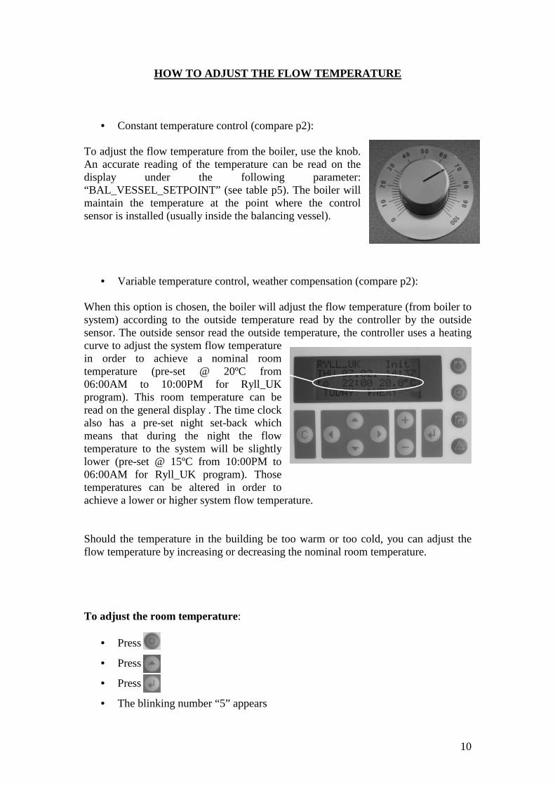
HOW TO ADJUST THE FLOW TEMPERATURE
• Constant temperature control (compare p2): To adjust the flow temperature from the boiler, use the knob. An accurate reading of the temperature can be read on the display under the following parameter: “BAL_VESSEL_SETPOINT” (see table p5). The boiler will maintain the temperature at the point where the control sensor is installed (usually inside the balancing vessel).
• Variable temperature control, weather compensation (compare p2): When this option is chosen, the boiler will adjust the flow temperature (from boiler to system) according to the outside temperature read by the controller by the outside sensor. The outside sensor read the outside temperature, the controller uses a heating curve to adjust the system flow temperature in order to achieve a nominal room temperature (pre-set @ 20ºC from 06:00AM to 10:00PM for Ryll_UK program). This room temperature can be read on the general display . The time clock also has a pre-set night set-back which means that during the night the flow temperature to the system will be slightly lower (pre-set @ 15ºC from 10:00PM to 06:00AM for Ryll_UK program). Those temperatures can be altered in order to achieve a lower or higher system flow temperature. Should the temperature in the building be too warm or too cold, you can adjust the flow temperature by increasing or decreasing the nominal room temperature. To adjust the room temperature:
• Press
• Press
• Press
• The blinking number “5” appears

11
• Use & to display the number “3” and then press
• Use & to display the number “3” and then press
• Use & to display the number “3” and then press
• Use & to display the number “3” and then press
• The word “CHANGE” appears in the bottom left corner
• Press
• The menu of the time clock is now
displayed with the following
category:
� System Time
� Daily
� Weekly
� Annual
• Move the arrow in front of “DAILY” using & then press
• Press
• Move the arrow in front of “MODIFY” and then press
• The following menu appears:
There are 3 different time clock programs:
� Ryll_UK
� Ryll_UK_weekend
� Ryll_UK_Friday
Ryll_UK programme is used for Mondays, Tuesdays,
Wednesdays and Thursdays
Ryll_UK_weekend programme is used for Saturdays and Sundays
Ryll_UK_Friday programme is used for Fridays

12
Those programmes all vary in term of night set back duration (from 10:00PM to
06:00AM for Ryll_UK, from 10:00PM to 08:00AM for Ryll_UK_weekend) and in
term of controls for DHW pump, heating pump, shunt pump, DHW temperature…
To adjust the room temperature, you need
to access the time clock programme, for
example, should you want to change the
time the night-set back ends, just access
Ryll_UK programme, the following screen
appears
• Move the arrow in front of “06:00 room_tem” and then press
• The following display will appear,
this means that from 6:00AM the
room temperature is set @ 20ºC.
Should you want to change the
time or increase the temperature
move the arrow & & in front
of the date or the time and then press to select and use & to adjsut
it . Repeat the procedure to change the time and temperature durin the day.
Should you wish to keep the same room temperature night & day please set
any “room-tem” to the same settings
• The above procedure shows how to adjust the room temperature (and
consequently the flow temperature for the “RYLL_UK” program should you
wish the change to be valid for all day of the week, repeat the procedure in the
“Ryll_UK_weekend” and “Ryll_UK_Friday” programs.
Should any clarifiaction be required, please contact ATLANTIC:
0161 621 5960

13
SERVICE OF THE BOILER
Atlantic advises that the R series is serviced
� Every year or every 2500 to 3000 hours run (whichever comes first) for gas or
LPG fired boilers
� Every six-months or every 1500 to 2000 hours run (whichever comes first) for
oil, keresone or rapeseed oil fired boilers
To check the hours run:
• From main diplay
• Press
• Press
• Press
• Move the arrow down in front of “HOURS RUN” using & and press
• Move the arrow down in front of “BURNER_LOW” using &
• Press
• The following display appears
and give the number of hours for
which the burner has been firing
since commissioning

14
FAULT FINDING CHART
A1 Check the main switch is on (N1)A2 Check mains power on the boilerA3 Check boiler fuses (N2)A4 Check all gasses valves are turned onA5 Check that oil supply is turned onA6 Check the firevalves (if installed)A7 Check the transformer (N30)
B1 Check the shunt pump (N9) for overload
B2 Check the DHW pump overload (if controlled with the boiler)B3 Check Heating pump overload (if controlled with the boiler)B4 Check the secondary DHW pump overload (if controlled with the boiler)
B5Disconnect the fan plugs (N3), replace the fuse and reconnect it. Should the fuse blow again, please ring Atlantic.
B6 Check the limit stats (N18,19,21) (no live on earth connection)
B7Check the pressure board (N8) disconnect the pressure board power supply plug (N37), replace the fuse and reconnect it. Should the fuse blow again, please ring Atlantic.
B8Check the burner, disconnect the burner plug (N5), replace the fuse and reconnect it. Should the fuse blow again, please ring Atlantic.
B9Check the boiler diverting valve (N7), (disconnect terminal 6 & 7 or 9 & 10 on X1 control box (N27), replace the fuse and reconnect it. Should the fuse blow again, please ring Atlantic.
C1Check that all the system pumps are running, valves are open and strainers are clean.
C2If boiler is running at constant temperature, check that the potentiometre (N10) is set correctly. Precise adjustment can be done using the display : (Analog Input, "Bsv_set_point")
C3Check the enable signal if boiler enable by BMS (terminal 11 or 13 on X1 control box)
C4 Check the control sensor (terminal 12 & 14 on X1 control box)
C5Check that the temperature on the honeywell controller is relevant (Analog Input, "Bal_vessel_temp" or "Htg1_temp")
C6 Check the diverting valve for any failure and manually move it
C7Cool down the boiler and check that the boiler flow & return temperature (Analog Input, "Boiler_flow_temp" & "Boiler_return_temp" are rising simultaneous, if not check the boiler shunt pump (N9)
D1 Press the pressure reset button (N11)D2 Check the flue ways for any obstuctrions, clear if necessary. D3 Check that the condensate drain (N15) is on the "operation position"D4 Check that the flue is not filled with condensateD5 Check that there are no obstructions to condensate drainD6 Check that the condensing heat exchanger (N12) is filled with waterD7 Check that the exctracting fan(s) (N13) have correct rotation (anti clock-wise)D8 Check the pressure board fuse (N14) D9 Check the fan plug (N3)
D10Check that the silicone tube is clear and connected to P2 on the pressure switch (N16) and the combustion chamber
D11 Check that all connections on the pressure board (N8) are tight
D12Check that the main heat exchanger (N20) is clean, if not contact Atlantic or service the boiler.
D13Check that the pressure in the combustion chamber is -0.25mbar using an analyser and the inspection point (N17), if not contact Atlantic
Switch is on but fuse keeps on blowing
B
Indication Likely cause & possible remedy
C
Boiler is switched on, burner is running, boiler is warm, but system is
cold
Display shows "Comb_fault"
D
Nothing happen at switch on
A
15
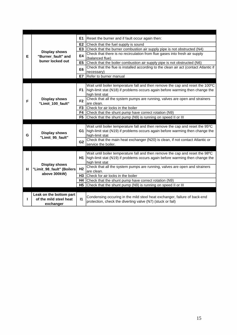
E1 Reset the burner and if fault occur again then:
E2 Check that the fuel supply is soundE3 Check that the burner combustion air supply pipe is not obstructed (N4)
E4Check that there is no recirculation from flue gases into fresh air supply (balanced flue)
E5 Check that the boiler combustion air supply pipe is not obstructed (N6)
E6Check that the flue is installed according to the clean air act (contact Atlantic if necessary)
E7 Refer to burner manual
F1Wait until boiler temperature fall and then remove the cap and reset the 100ºC high-limit stat (N18) if problems occurs again before warming then change the high limit stat
F2Check that all the system pumps are running, valves are open and strainers are clean.
F3 Check for air locks in the boilerF4 Check that the shunt pump have correct rotation (N9)F5 Check that the shunt pump (N9) is running on speed II or III
G1Wait until boiler temperature fall and then remove the cap and reset the 95ºC high-limit stat (N19) if problems occurs again before warming then change the high-limit stat
G2Check that the main heat exchanger (N20) is clean, if not contact Atlantic or service the boiler.
H1Wait until boiler temperature fall and then remove the cap and reset the 98ºC high-limit stat (N19) if problems occurs again before warming then change the high limit stat
H2Check that all the system pumps are running, valves are open and strainers are clean.
H3 Check for air locks in the boilerH4 Check that the shunt pump have correct rotation (N9)H5 Check that the shunt pump (N9) is running on speed II or III
ILeak on the bottom part
of the mild steel heat exchanger
I1Condensing occuring in the mild steel heat exchanger, failure of back-end protection, check the diverting valve (N7) (stuck or fail)
Display shows "Limit_98_fault" (Boilers
above 300kW)H
Display shows "Burner_fault" and buner locked out
E
Display shows "Limit_100_fault"
F
Display shows "Limit_95_fault"
G

16
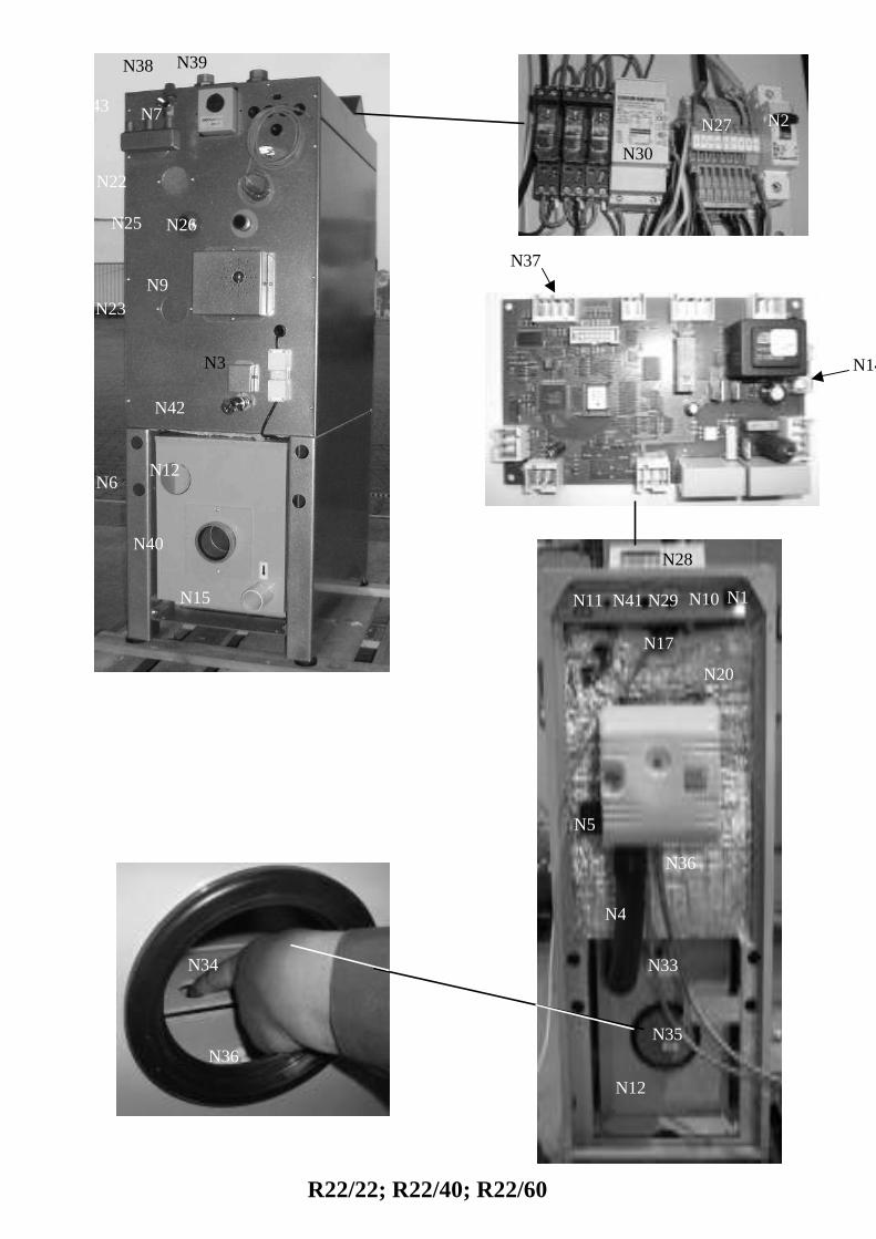
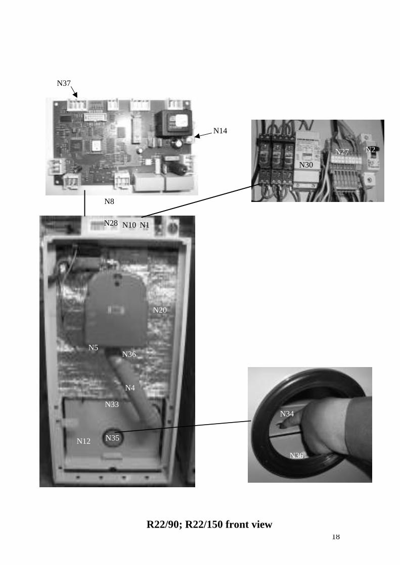
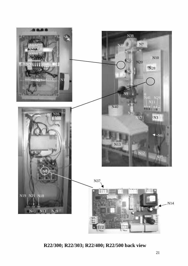
NOMENCLATURE
N44
N45
N22, N23 & N31
N16
N32
N1 Main SwitchN2 Boiler fuseN3 Fan PlugN4 Pre heated air pipeN5 Burner plugN6 Fresh air inletN7 Diverting valveN8 Pressure boardN9 Shunt pumpN10 PotentiometreN11 Pressure reset buttonN12 Condensing Heat exchangerN13 FanN14 Pressure board fuseN15 Condensate drainN16 Pressure switchN17 Inspection pointN18 High limit stat 100N19 High limit stat 95N20 Main heat exchangerN21 High limit stat 98N22 Boiler flow sensorN23 Boiler return sensorN24 NeutralizerN25 DHW flowN26 DHW returnN27 X1 control panelN28 XL40 Honeywell DisplayN29 High limit stat lamp alarmN30 TransformerN31 Boiler pocket sensor (control)N32 Boiler strapped sensor (control)N33 Flue gas test point N34 Plastic plateN35 Condensing exchanger front coverN36 Cleaning panelN37 Pressure board power supplyN38 Boiler flowN39 Boiler returnN40 Flue connectionN41 High limit stat resetN42 DrainN43 Safety valveN44 HandleN45 Outside sensor
Boiler sensor
Pressure switch
Strapped sensor
Outside sensor
Handle
17
N14
N37
N7
N3
N9
N12
N15
N22
N23
N25 N26
N38 N39
N40
N6
N42
N43
N1
N4
N5
N10 N11
N12
N17
N20
N28
N29N41
N33
N35
N36
N2 N27
N30
N36
N34
R22/22; R22/40; R22/60
18
N14
N37
N1
N5
N4
N10
N12
N20
N28
N2 N27
N30
N33
N35
N36
N8
R22/90; R22/150 front view
N36
N34

19
N7
N38
N39
N25
N26
N40
N13
N6
N15
N9
N12
N42
N23
N43
R22/90; R22/150 back view

20
N4
N5
N12
N20
N33
N35
N36
N36
N34
R22/300; R22/303; R22/400; R22/500 front view
21
N14
N37
N3
N7
N9
N10
N11 N41 N29
N12
N13
N15
N23
N25
N26
N28
N38
N39
N40
N42
N1
N2
N30
N27
N6
N20
N8
N16
N41 N11 N29
N19 N21 N18
R22/300; R22/303; R22/400; R22/500 back view
22
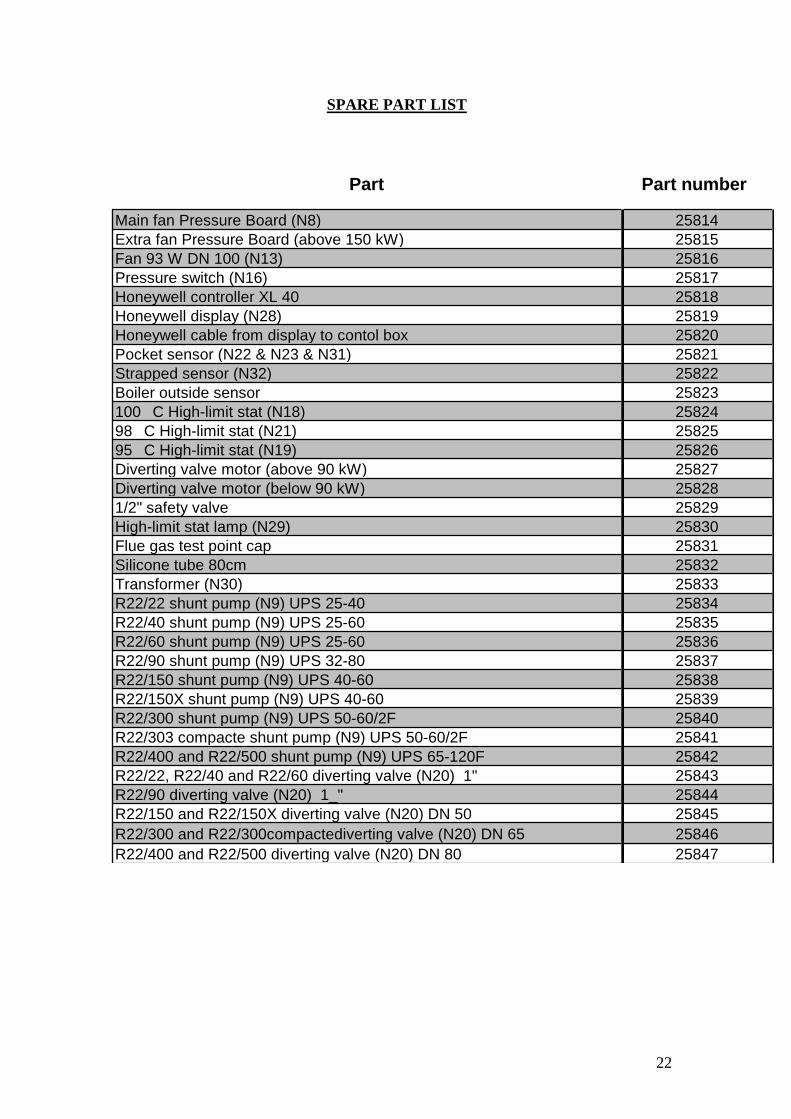
SPARE PART LIST
N19 N18 & N21
Part Part number
Main fan Pressure Board (N8) 25814Extra fan Pressure Board (above 150 kW) 25815Fan 93 W DN 100 (N13) 25816Pressure switch (N16) 25817Honeywell controller XL 40 25818Honeywell display (N28) 25819Honeywell cable from display to contol box 25820Pocket sensor (N22 & N23 & N31) 25821Strapped sensor (N32) 25822Boiler outside sensor 25823100�C High-limit stat (N18) 2582498�C High-limit stat (N21) 2582595�C High-limit stat (N19) 25826Diverting valve motor (above 90 kW) 25827Diverting valve motor (below 90 kW) 258281/2" safety valve 25829High-limit stat lamp (N29) 25830Flue gas test point cap 25831Silicone tube 80cm 25832Transformer (N30) 25833R22/22 shunt pump (N9) UPS 25-40 25834R22/40 shunt pump (N9) UPS 25-60 25835R22/60 shunt pump (N9) UPS 25-60 25836R22/90 shunt pump (N9) UPS 32-80 25837R22/150 shunt pump (N9) UPS 40-60 25838R22/150X shunt pump (N9) UPS 40-60 25839R22/300 shunt pump (N9) UPS 50-60/2F 25840R22/303 compacte shunt pump (N9) UPS 50-60/2F 25841R22/400 and R22/500 shunt pump (N9) UPS 65-120F 25842R22/22, R22/40 and R22/60 diverting valve (N20) 1" 25843R22/90 diverting valve (N20) 1_" 25844R22/150 and R22/150X diverting valve (N20) DN 50 25845R22/300 and R22/300compactediverting valve (N20) DN 65 25846R22/400 and R22/500 diverting valve (N20) DN 80 25847