Embed Size (px)
Citation preview

USER MANUAL Maxwell Technologies® Ultracapacitor Energy Storage Modules for Heavy Duty Transportation Applications User Manual for 125 V Modules:
BMOD0063 P125 B24 BMOD0063 P125 B14 BMOD0063 P125 B04 BMOD0063 P125 B33 BMOD0063 P125 B03 BMOD0063 P125 B08 BMOD0063 P125 Cxx
Document 1014343

Notice: The products described herein are covered by one or more of the following patents: 7307830,
7203056, 7027290, 7352558, 7295423, 7090946, 7508651, 7492571, 7342770, 6643119, 7384433, 7147674, 7317609, 7495349, 7102877

User Manual – BMOD0063 version 2.2 Page 1 Document no.: 1014343.8 © 2008-2014 Maxwell Technologies, Inc. ®
WARNING
DANGER – HIGH VOLTAGE HAZARD!
Never touch the power terminals as the module can be charged and cause
fatal electrical shocks. Always check that the module is fully discharged
before manipulating the module. Please refer to the step by step instructions in the Safety section of this manual for the manual discharge
procedure.
WARRANTY LIMITATION
Do not open or modify the module. Opened or modified modules are no longer covered by warranty and are unserviceable property of the customer.
1. Introduction
The 125 V heavy transportation modules are self-contained energy storage devices comprised of 48
individual ultracapacitor cells. The modules include bus bar connections, and integral voltage management circuitry. Units may be connected in series to obtain higher operating voltages, parallel to
provide additional energy storage, or a combination of series/parallel arrangements for higher voltages and energy. 125 V modules must never be connected to other types of modules in any way. Thermal
monitoring and electronic voltage management circuitry is incorporated into each of the heavy
transportation modules. The voltage management circuitry functions primarily to protect every cell from operating in a damaging over voltage condition.
The module is equipped with Maxwell Voltage Monitoring System. This system monitors the voltages of six (6) groups of 8 cell strings, as well as the temperature. The values of these measurements as well as
cell temperature can be retrieved by CAN communication. Models B03 and B33 output voltage
measurements via an analog connector which provides half module voltages.
The heavy transportation module is built with heavy-duty extruded aluminum enclosures. The modules
are cooled using two DC axial fans and two large, finned heat sinks which make up the top and bottom of the enclosure. Sheet metal shrouds make up the air passage and direct the cooling air over the heat
sinks. The module is permanently sealed, water-resistant per IEC 60529 – IP65, and require no internal maintenance. The power terminals are fully enclosed in a water-resistant junction box. The low voltage
CAN connectors, chassis vent, and earth ground stud are selected to be suitable for heavy transportation
environments.
Model B08 has been e-mark certified to 72/245/EEC and UN/ECE 10.03 for public transportation. The
corresponding fan kit, part number 129036, has been similarly certified to 72/245/EEC.
2. Unpacking
Inspect the shipping crate for signs of damage prior to unpacking the module. Damage to the shipping
crate or module should be reported to the carrier immediately.
User Manual – BMOD0063 version 2.2 Page 2 Document no.: 1014343.8 © 2008-2014 Maxwell Technologies, Inc. ®
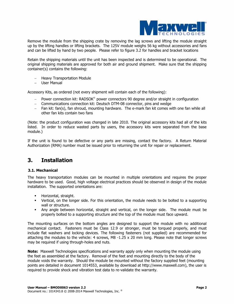
Remove the module from the shipping crate by removing the lag screws and lifting the module straight
up by the lifting handles or lifting brackets. The 125V module weighs 56 kg without accessories and fans and can be lifted by hand by two people. Please refer to figure 3.2 for handles and bracket locations
Retain the shipping materials until the unit has been inspected and is determined to be operational. The original shipping materials are approved for both air and ground shipment. Make sure that the shipping
container(s) contains the following:
Heavy Transportation Module
User Manual
Accessory Kits, as ordered (not every shipment will contain each of the following):
Power connection kit: RADSOK power connectors 90 degree and/or straight in configuration
Communications connection kit: Deutsch DTM-08 connector, pins and wedge
Fan kit: fan(s), fan shroud, mounting hardware. The e-mark fan kit comes with one fan while all
other fan kits contain two fans
(Note: the product configuration was changed in late 2010. The original accessory kits had all of the kits
listed. In order to reduce wasted parts by users, the accessory kits were separated from the base
module.)
If the unit is found to be defective or any parts are missing, contact the factory. A Return Material
Authorization (RMA) number must be issued prior to returning the unit for repair or replacement.
3. Installation
3.1. Mechanical
The heavy transportation modules can be mounted in multiple orientations and requires the proper hardware to be used. Good, high voltage electrical practices should be observed in design of the module
installation. The supported orientations are:
Horizontal, straight.
Vertical, on the longer side. For this orientation, the module needs to be bolted to a supporting
wall or structure. Any angle between horizontal, straight and vertical, on the longer side. The module must be
properly bolted to a supporting structure and the top of the module must face upward.
The mounting surfaces on the bottom angles are designed to support the module with no additional
mechanical contact. Fasteners must be Class 12.9 or stronger, must be torqued properly, and must
include flat washers and locking devices. The following fasteners (not supplied) are recommended for attaching the modules to the vehicle: 4 screws, M8 -1.25 x 20 mm long. Please note that longer screws
may be required if using through-holes and nuts.
Note: Maxwell Technologies specifications and warranty apply only when mounting the module using
the feet as assembled at the factory. Removal of the feet and mounting directly to the body of the module voids the warranty. Should the module be mounted without the factory supplied feet (mounting
points are detailed in document 1014553, available by download at http://www.maxwell.com), the user is
required to provide shock and vibration test data to re-validate the warranty.
User Manual – BMOD0063 version 2.2 Page 3 Document no.: 1014343.8 © 2008-2014 Maxwell Technologies, Inc. ®
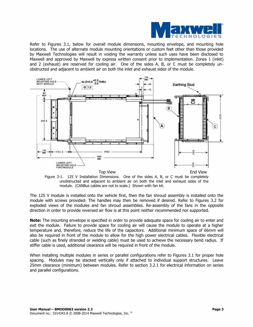
Refer to Figures 3.1, below for overall module dimensions, mounting envelope, and mounting hole
locations. The use of alternate module mounting orientations or custom feet other than those provided by Maxwell Technologies will result in voiding the warranty unless such uses have been disclosed to
Maxwell and approved by Maxwell by express written consent prior to implementation. Zones 1 (inlet) and 2 (exhaust) are reserved for cooling air. One of the sides A, B, or C must be completely un-
obstructed and adjacent to ambient air on both the inlet and exhaust sides of the module.
Top View End View
Figure 3-1. 125 V Installation Dimensions. One of the sides A, B, or C must be completely
unobstructed and adjacent to ambient air on both the inlet and exhaust sides of the module. (CANBus cables are not to scale.) Shown with fan kit.
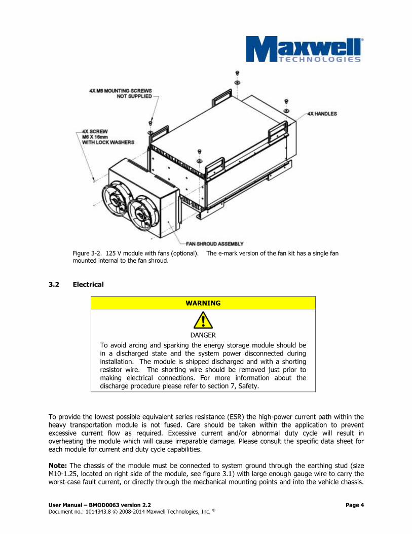
The 125 V module is installed onto the vehicle first, then the fan shroud assembly is installed onto the module with screws provided. The handles may then be removed if desired. Refer to Figures 3.2 for
exploded views of the modules and fan shroud assemblies. Re-assembly of the fans in the opposite direction in order to provide reversed air flow is at this point neither recommended nor supported.
Note: The mounting envelope is specified in order to provide adequate space for cooling air to enter and
exit the module. Failure to provide space for cooling air will cause the module to operate at a higher temperature and, therefore, reduce the life of the capacitors. Additional minimum space of 66mm will
also be required in front of the module to allow for the high power electrical cables. Flexible electrical cable (such as finely stranded or welding cable) must be used to achieve the necessary bend radius. If
stiffer cable is used, additional clearance will be required in front of the module.
When installing multiple modules in series or parallel configurations refer to Figures 3.1 for proper hole spacing. Modules may be stacked vertically only if attached to individual support structures. Leave
25mm clearance (minimum) between modules. Refer to section 3.2.1 for electrical information on series and parallel configurations.
User Manual – BMOD0063 version 2.2 Page 4 Document no.: 1014343.8 © 2008-2014 Maxwell Technologies, Inc. ®
Figure 3-2. 125 V module with fans (optional). The e-mark version of the fan kit has a single fan mounted internal to the fan shroud.
3.2 Electrical
WARNING
DANGER
To avoid arcing and sparking the energy storage module should be
in a discharged state and the system power disconnected during
installation. The module is shipped discharged and with a shorting resistor wire. The shorting wire should be removed just prior to
making electrical connections. For more information about the discharge procedure please refer to section 7, Safety.
To provide the lowest possible equivalent series resistance (ESR) the high-power current path within the heavy transportation module is not fused. Care should be taken within the application to prevent
excessive current flow as required. Excessive current and/or abnormal duty cycle will result in overheating the module which will cause irreparable damage. Please consult the specific data sheet for
each module for current and duty cycle capabilities.
Note: The chassis of the module must be connected to system ground through the earthing stud (size M10-1.25, located on right side of the module, see figure 3.1) with large enough gauge wire to carry the
worst-case fault current, or directly through the mechanical mounting points and into the vehicle chassis.

User Manual – BMOD0063 version 2.2 Page 5 Document no.: 1014343.8 © 2008-2014 Maxwell Technologies, Inc. ®
Customer should supply a nut with these threads and also use of a lock washer is recommended. The
earth stud is made of stainless steel and the nut should not be torqued above 35 N-m.
3.2.1 High Power Connection
The high power electrical connections are made within a sealed junction box mounted to the front of the module The connectors also use proprietary Radsok® contacts which provide low insertion force and
reliable low resistance capability. These connectors must be mated with the correct Amphenol lugs,
available in the accessory kit (see Section 5 for part numbers). The mating connectors accept cables with a maximum conductor OD of 11.1mm (90 degree connector) or 9.1mm (straight connector). If
using another size, the cable should have the correct size & temp rating for the application current. Cables which are too small can add a significant amount of resistance to the installation, reducing system
efficiency and generating heat. The following steps need to be taken in order to properly assemble the junction box and power connections:
1) Unpack the accessory kit.
2) Using a holesaw (not provided) with the proper diameter, drill both cable holes at the desired location on the junction box housing or junction box lid. Maxwell provides 2x M25 fittings but
diameters up to M32 can be supported by the junction box. The 2 holes can be on any of the 4 sides or on the lid of the junction box depending on the customer’s implementation in vehicle.
Figure 3-3. Junction box with 2 holes. Holes may be drilled on any side or on the cover.

User Manual – BMOD0063 version 2.2 Page 6 Document no.: 1014343.8 © 2008-2014 Maxwell Technologies, Inc. ®
3) Install the 2x M25 fittings in the holes.
Figure 3-4. Fittings assembly
4) Trim the power cables (not provided) to the appropriate lengths.
5) Install the junction box housing and fasten it to the front panel using the 8x M5 screws and #10
washers with a 6 N-m torque. Apply Loctite 271 (provided) to the screws before installing.
Figure 3-5. Junction box assembly on the module. (CANBus cables not to scale.)
User Manual – BMOD0063 version 2.2 Page 7 Document no.: 1014343.8 © 2008-2014 Maxwell Technologies, Inc. ®
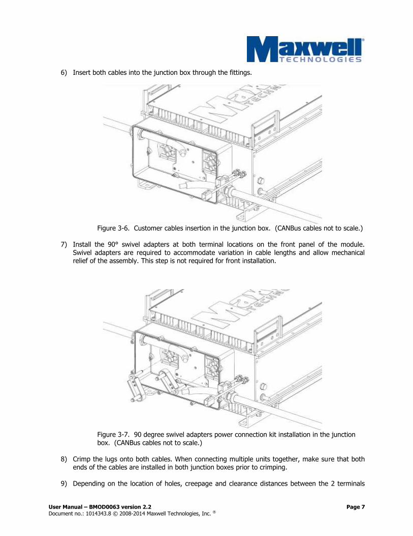
6) Insert both cables into the junction box through the fittings.
Figure 3-6. Customer cables insertion in the junction box. (CANBus cables not to scale.)
7) Install the 90° swivel adapters at both terminal locations on the front panel of the module.
Swivel adapters are required to accommodate variation in cable lengths and allow mechanical relief of the assembly. This step is not required for front installation.
Figure 3-7. 90 degree swivel adapters power connection kit installation in the junction
box. (CANBus cables not to scale.)
8) Crimp the lugs onto both cables. When connecting multiple units together, make sure that both ends of the cables are installed in both junction boxes prior to crimping.
9) Depending on the location of holes, creepage and clearance distances between the 2 terminals

User Manual – BMOD0063 version 2.2 Page 8 Document no.: 1014343.8 © 2008-2014 Maxwell Technologies, Inc. ®
may be too short and require extra isolation. To maintain the proper creepage distance for an
operating voltage of 1000V, we recommend at least 19.1 mm through air. For this purpose, install and clip the plastic covers around both cable lugs. This step is not required for front
installation.
Figure 3-8. Swivel adapters cover assembly. (CANBus cables not shown.)
10) Connect both power cable lugs to the respective terminal pins by pressing them in all the way.
Figure 3-9. Final connector assembly. (CANBus cables not to scale.)
11) For the side assembly, tighten the 2 fittings to ensure proper stability and water resistance of the assembly. For the front assembly, it is recommended to measure the length of the section of
cables inside the junction box to make sure they will properly fit and provide enough slack. Then unplug the pin power connectors, tighten the 2 fittings and re-plug the pins at both power
terminal locations.

User Manual – BMOD0063 version 2.2 Page 9 Document no.: 1014343.8 © 2008-2014 Maxwell Technologies, Inc. ®
Alternately, for multi module implementations with short cables, the junction box can be
mounted on the module after cable insertion, fitting and crimping.
12) Install the lid and tighten the 4x M4 screw and washers with a torque of 3 Nm. Apply Loctite 271
(provided) to screws before installing.
Figure 3-10. Lid assembly on the junction box. (CANBus cables not to scale.)
Connection of modules in series or parallel should be done with the same gauge wire as determined for final output connections. When connecting in series connect the positive output terminal of one module
to the negative output terminal of the next module. Parallel arrangements require tee connections in the cable (not supplied).
Up to twelve (12) 125 V modules may be connected in series for high voltage applications. This
corresponds to a maximum system voltage of 1500 VDC. Isolation of the modules is tested to 4000 VDC. The modules should not be used in higher voltage environments. If higher voltage is desired, please
contact your Maxwell representative. When several modules are connected in series for operating at higher voltage, care must be taken to ensure proper creepage and clearance distances in compliance with
national safety standards for electrical equipment.
3.2.2 CAN Monitor – Configuration B04/B08/B14/B24/Cxx
CAN Bus communications protocols, data formats and commands are covered in a separate manual. For
a detailed description of the communication protocol, please refer to the document “Maxwell Technologies CAN Communication Specification” (document number 1014339). The latest version may
be found at http://www.maxwell.com.
3.2.2.1 Connection
The HTM125 Ultracapacitor Module is equipped with two 8 pin Deutsch connectors each on a short cable.
One of the connectors is a Socket Plug and one is a Pin Receptacle for easy daisy chaining.

User Manual – BMOD0063 version 2.2 Page 10 Document no.: 1014343.8 © 2008-2014 Maxwell Technologies, Inc. ®
Connector Type Socket Plug Pin Receptacle
Drawing Overview
Connector PN DTM06-08SA DTM04-08PA
Wedgelock PN WM-8S WM-8D
Socket / Pin PN 0460-202-20141 0462-201-20141
Connector Pin Out
Description Pin
CAN_H 1
CAN_L 2
SHIELD 3
NC 4
NC 5
NC 6
24 RTN 7
24 VDC 8
3.2.2.2 Voltage Monitoring
The CAN Monitor measures the voltage from the negative terminal to every 8th cell and transmits the
values over the CAN bus to the network master. For a detailed description of the communication protocol, please refer to the document “Maxwell Technologies CAN Communication Specification” (1014339). The
latest version of the communication protocol and this manual can be downloaded at http://www.maxwell.com.
Every pack will have a unique separation of voltages across the 8-cell string due to differences in cell
capacitances, interconnect resistance variances, and other native cell contributions. Therefore, the pack should be measured for its baseline condition, which should have a variance of less than 3 V when first
energized after the module is received from the factory. The difference in the 8-cell string voltages should be regularly monitored during use as it is can be used as a performance indicator for that module.
If the voltage across any two 8-cell strings diverge from each other over use and time such that the
voltage difference is greater than 3V, the monitor sends a warning flag via the CAN bus. When this happens, a reconditioning cycle should be applied in order to bring the strings back into better balance.
When multiple (N) modules are connected in series, the voltages of all 8 cell strings (N x 6 measurements) should be monitored through the CAN communications.. Calculate the difference
between the maximum string voltage measured and the minimum string voltage measured. This difference is the Peak Delta Voltage for the system (This is different than the Peak Delta Voltage which
can be read through CAN communication as the direct reading is the difference only within a particular

User Manual – BMOD0063 version 2.2 Page 11 Document no.: 1014343.8 © 2008-2014 Maxwell Technologies, Inc. ®
module.). It should be compared to the table values below. If the difference in voltages exceeds the
table value, a reconditioning cycle should be performed.
Series Connected Reconditioning Triggers
Number of Modules in
Series
Peak Delta Voltage
Trigger
1 3.0V*
2 3.0
3 2.9
4 2.8
5 2.7
6 to 12 2.6
* This is the value which sets the flag in CAN communications for each module.
3.2.2.3 The reconditioning cycle is the following:
1. Charge the series of modules to 129.6 V x Number of Modules in Series for 5 minutes. Monitor the 8-cell string voltages and the Peak Delta Voltage as reported via the CAN bus.
2. Disable/Disconnect the charging source. Ensure that no leakage current occurs between the
charging source and the module.
3. Monitor the 8-cell string voltages and peak delta voltage using the CAN bus. The voltage
management circuits will work to reduce the cell voltage. Check the peak delta voltage when each module voltage has drained to about 125 V or when the total voltage across all series
connected modules is Nx125V. This should take about 10 – 15 min. If the peak delta is now
lower than 1 V, the reconditioning is finished and the module can be put back in operation. If the peak delta voltage is larger than 1V, redo the reconditioning cycle from point 1 above.
In the chance event that the voltages do not converge during the reconditioning cycle the active balancing electronics is not functioning correctly. Please contact your Maxwell application/sales engineer
for further assistance.
3.2.3 Analog Monitor – Configuration B33
WARNING
DANGER – HIGH VOLTAGE HAZARD!
Never touch any of the tap pins as the module can be charged and cause fatal electrical shocks.
Always check that the module is fully discharged before manipulating the module. Please refer to the step by step instructions below for the manual
discharge procedure.
User Manual – BMOD0063 version 2.2 Page 12 Document no.: 1014343.8 © 2008-2014 Maxwell Technologies, Inc. ®
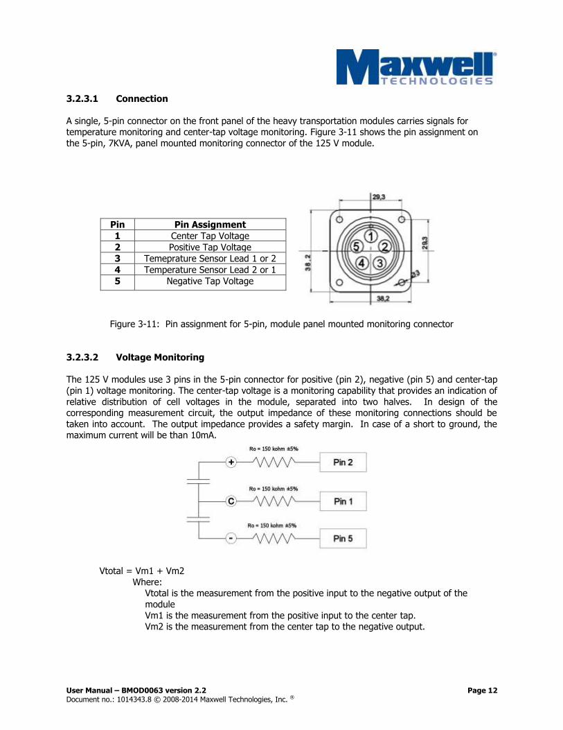
3.2.3.1 Connection
A single, 5-pin connector on the front panel of the heavy transportation modules carries signals for temperature monitoring and center-tap voltage monitoring. Figure 3-11 shows the pin assignment on
the 5-pin, 7KVA, panel mounted monitoring connector of the 125 V module.
Pin Pin Assignment
1 Center Tap Voltage
2 Positive Tap Voltage
3 Temeprature Sensor Lead 1 or 2
4 Temperature Sensor Lead 2 or 1
5 Negative Tap Voltage
Figure 3-11: Pin assignment for 5-pin, module panel mounted monitoring connector
3.2.3.2 Voltage Monitoring
The 125 V modules use 3 pins in the 5-pin connector for positive (pin 2), negative (pin 5) and center-tap
(pin 1) voltage monitoring. The center-tap voltage is a monitoring capability that provides an indication of
relative distribution of cell voltages in the module, separated into two halves. In design of the corresponding measurement circuit, the output impedance of these monitoring connections should be
taken into account. The output impedance provides a safety margin. In case of a short to ground, the maximum current will be than 10mA.
Vtotal = Vm1 + Vm2
Where: Vtotal is the measurement from the positive input to the negative output of the
module
Vm1 is the measurement from the positive input to the center tap. Vm2 is the measurement from the center tap to the negative output.
User Manual – BMOD0063 version 2.2 Page 13 Document no.: 1014343.8 © 2008-2014 Maxwell Technologies, Inc. ®
It is recommended that the measurement circuit have an input impedance of at least 100 times the
output impedance of the device being measured. If the input impedance is lower than this, a scaling factor will need to be applied.
Voutput = Vmeasured x [(Rinput+Routput)/Rinput]
Every pack will have a unique separation of the two halves due to differences in cell capacitance, interconnect resistance variances, initial state of charge separations, native cell leakage current variations
and other known contributions. Therefore, the pack should be measured for its baseline condition, which should have a variance of less than 4 V when first energized after the module is received from the
factory. The difference in the half pack voltages should be regularly monitored during use as it is a performance indicator for that module and may change as the module ages. A monitoring frequency of
once per day would be sufficient (may be less frequent depending on the application). Little value will be
gained by monitoring more frequently. If the two halves of the pack diverge from each other over use and time such that the voltage difference between halves is greater than 6V, a reconditioning cycle
should be applied in order to bring the halves back into better balance. The reconditioning will not only bring the halves back to balance but also can help determine the cause of this divergence. The
reconditioning cycle is the following:
Charge the module to 129.6 V (or the module string to 129.6V x number of modules in series) and hold
on charge for 5 minutes. At this time measure the half pack voltages. Given effective working voltage management circuitry, the half pack voltages will be below the 4 V maximum range after conditioning. If
that is not the case, contact your applications engineer for further information. If that is the case, then the module can be put back into service. Monitoring of the half pack voltages can then resume as was
the case before exceeding the 6 V limits. Assuming the rate of change of the two half pack voltages is
similar to what it was before the conditioning process was performed, the indication is that the module is functioning normally. Excessive divergent voltage rates in the halves or step functions in the half pack
voltages which cause them to separate will indicate possible defect conditions in the pack.
A 5-pin mating connector for the monitor output is provided as part of the accessory kit (see Section 5 for
part numbers). 22 gauge wire may be used to make cables up to 6 feet (1.8 m) in length. For lengths longer than 6 feet (1.8 m) shielded wire is recommended.
3.2.4 Temperature Monitoring
3.2.4.1 Temperature Sensors
The 125 V module uses a temperature sensor within the module at a location which is representative of the cell population temperature. See Figure 3-12 for a diagram of the temperature sensor location on
the 125 V module.

User Manual – BMOD0063 version 2.2 Page 14 Document no.: 1014343.8 © 2008-2014 Maxwell Technologies, Inc. ®
Figure 3-12. Temperature Sensor Diagram for the 125 V Module (shown with optional fans)
3.2.4.1.2 Digital Monitoring
The CAN Monitor measures the temperature and sends the value over the CAN bus to the network
master. The CAN Monitor also compares the measured temperature to pre-set warning and alarm levels. If the temperature is outside of the operating range, a flag will be set as an indication to the master. For
detailed description of the communication protocol please refer to the document “Maxwell Technologies
CAN Communication Specification” (document number 1014339).
3.2.4.1.2 Analog Monitoring (Configuration B33)
The temperature output is via a PT100 RTD temperature sensor. The resistance of the RTD varies with temperature to provide actual temperature of the module. The resistance measured through the RTD
relates to temperature according to the temperature chart for the Minco part S17624PDYT15BC
(EN60751, Class B, 100 Ohm @ 0ºC) www.minco.com.
3.2.4 Fan Connection
The 125 V modules are cooled by two 12 V or 24 V DC axial cooling fans. The fans each have two
30.5mm, 22 gauge (0.64mm) wires for electrical interconnection. (red = positive, black = negative). The wires are un-terminated to allow for maximum customer flexibility in providing power and connection to
the fans. The fans can draw up to 2.3A each.
4. Thermal Considerations
Low internal resistance of the energy storage modules results in relatively low internal heat generation within the modules during use. However, the high demands of heavy transportation warrant the use of
heat sinks and cooling fans to keep the cells at a low, uniform temperature. Operating the module at a
temperature above 65oC will void the module warranty. As with all electronic components, ultracapacitors have a longer service life when kept at a lower temperature. The thermal resistance, Rth, of the units has
been experimentally determined assuming forced convection at ambient (~ 25oC). The Rth value provided on the data sheet is useful for determining the operating limits for the units. Using the Rth value
a module temperature rise can be determined based upon any current and duty cycle. The temperature rise can be expressed by the following equation:
User Manual – BMOD0063 version 2.2 Page 15 Document no.: 1014343.8 © 2008-2014 Maxwell Technologies, Inc. ®
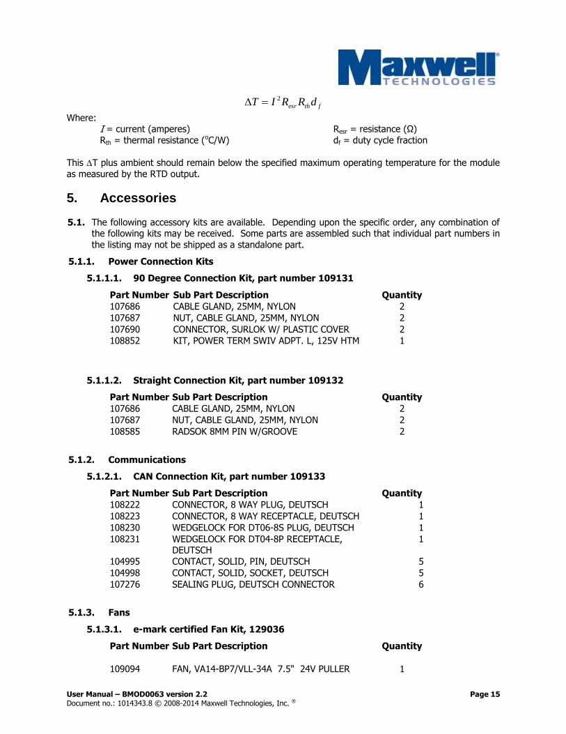
fthesr dRRIT 2
Where: I = current (amperes) Resr = resistance (Ω)
Rth = thermal resistance (oC/W) df = duty cycle fraction
This T plus ambient should remain below the specified maximum operating temperature for the module
as measured by the RTD output.
5. Accessories
5.1. The following accessory kits are available. Depending upon the specific order, any combination of the following kits may be received. Some parts are assembled such that individual part numbers in
the listing may not be shipped as a standalone part.
5.1.1. Power Connection Kits
5.1.1.1. 90 Degree Connection Kit, part number 109131
Part Number Sub Part Description Quantity
107686 CABLE GLAND, 25MM, NYLON 2
107687 NUT, CABLE GLAND, 25MM, NYLON 2
107690 CONNECTOR, SURLOK W/ PLASTIC COVER 2
108852 KIT, POWER TERM SWIV ADPT. L, 125V HTM 1
5.1.1.2. Straight Connection Kit, part number 109132
Part Number Sub Part Description Quantity
107686 CABLE GLAND, 25MM, NYLON 2
107687 NUT, CABLE GLAND, 25MM, NYLON 2
108585 RADSOK 8MM PIN W/GROOVE 2
5.1.2. Communications
5.1.2.1. CAN Connection Kit, part number 109133
Part Number Sub Part Description Quantity
108222 CONNECTOR, 8 WAY PLUG, DEUTSCH 1
108223 CONNECTOR, 8 WAY RECEPTACLE, DEUTSCH 1
108230 WEDGELOCK FOR DT06-8S PLUG, DEUTSCH 1
108231 WEDGELOCK FOR DT04-8P RECEPTACLE, DEUTSCH
1
104995 CONTACT, SOLID, PIN, DEUTSCH 5
104998 CONTACT, SOLID, SOCKET, DEUTSCH 5
107276 SEALING PLUG, DEUTSCH CONNECTOR 6
5.1.3. Fans
5.1.3.1. e-mark certified Fan Kit, 129036
Part Number Sub Part Description Quantity
109094 FAN, VA14-BP7/VLL-34A 7.5" 24V PULLER 1
User Manual – BMOD0063 version 2.2 Page 16 Document no.: 1014343.8 © 2008-2014 Maxwell Technologies, Inc. ®
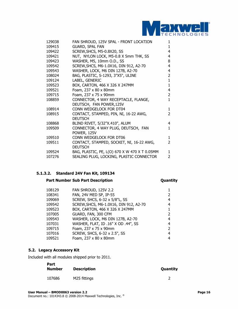
129038 FAN SHROUD, 125V SPAL - FRONT LOCATION 1
109415 GUARD, SPAL FAN 1
109422 SCREW,SHCS, M5-0.8X20, SS 4
109421 NUT, NYLON LOCK, M5-0.8 X 5mm THK, SS 4
109423 WASHER, M5, 10mm O.D., SS 8
109542 SCREW,SHCS, M6-1.0X16, DIN 912, A2-70 4
109543 WASHER, LOCK, M6 DIN 127B, A2-70 4
108024 BAG, PLASTIC, S-1293, 3"X5", ULINE 2
109124 LABEL, GENERIC 1
109523 BOX, CARTON, 466 X 326 X 247MM 1
109521 Foam, 237 x 80 x 80mm 4
109715 Foam, 237 x 75 x 90mm 2
108859 CONNECTOR, 4 WAY RECEPTACLE, FLANGE,
DEUTSCH, FAN POWER,125V
1
108914 CONN WEDGELOCK FOR DT04 1
108915 CONTACT, STAMPED, PIN, NI, 16-22 AWG,
DEUTSCH
2
108868 BLIND RIVET, 5/32"X.410", ALUM 4
109509 CONNECTOR, 4 WAY PLUG, DEUTSCH, FAN
POWER, 125V
1
109510 CONN WEDGELOCK FOR DT06 1
109511 CONTACT, STAMPED, SOCKET, NI, 16-22 AWG,
DEUTSCH
2
109524 BAG, PLASTIC, PE, L(O) 670 X W 470 X T 0.05MM 1
107276 SEALING PLUG, LOCKING, PLASTIC CONNECTOR 2
5.1.3.2. Standard 24V Fan Kit, 109134
Part Number Sub Part Description Quantity
108129 FAN SHROUD, 125V 2.2 1
108341 FAN, 24V MED SP, IP-55 2
109069 SCREW, SHCS, 6-32 x 5/8"L, SS 4
109542 SCREW,SHCS, M6-1.0X16, DIN 912, A2-70 4
109523 BOX, CARTON, 466 X 326 X 247MM 1
107005 GUARD, FAN, 300 CFM 2
109543 WASHER, LOCK, M6 DIN 127B, A2-70 4
107031 WASHER, FLAT, ID .16" X OD .44", SS 4
109715 Foam, 237 x 75 x 90mm 2
107016 SCREW, SHCS, 6-32 x 2.5", SS 4
109521 Foam, 237 x 80 x 80mm 4
5.2. Legacy Accessory Kit
Included with all modules shipped prior to 2011.
Part
Number Description Quantity
107686 M25 fittings 2

User Manual – BMOD0063 version 2.2 Page 17 Document no.: 1014343.8 © 2008-2014 Maxwell Technologies, Inc. ®
107687 M25 fittings, Nuts 2
107941 Power terminal male/male swivel adapters 2 108585 Male pin/female crimp power connectors 2
107690 Lug connectors, with plastic isolation cover 2 107940 Junction box with seals 1
107642 Junction box lid 1
108222 Connector, 8-pos plug, DTM* 1 108223 Connector, 8-pos rec, DTM* 1
108230 Wedgelock for DTM06* 1 108231 Wedgelock for DTM04* 1
104995 Contact, solid, pin, Deutsch* 5 104998 Contact, solid, socket, Deutsch* 5
107693 Screw,TORX,M4-0.7x10mm, Zinc Plated 8
107990 Screw SHCS, M5-0.8X20, CLASS 12.9, Plated 8 106583 Washer,Lock,#10,SS 8
106775 Washer, Lock M4, SS 8 107993 Loctite 271 1
107728 Mating Monitor Connector ** 1
* CAN version (B04, B14, B24) only. ** Analog version (B33) only.
6. Operation
The heavy transportation modules should only be operated within specified voltage and temperature
ratings. Determine whether current limiting is necessary on input/output based on current ratings of ancillary devices. Observe polarity indicated on module.
User Manual – BMOD0063 version 2.2 Page 18 Document no.: 1014343.8 © 2008-2014 Maxwell Technologies, Inc. ®
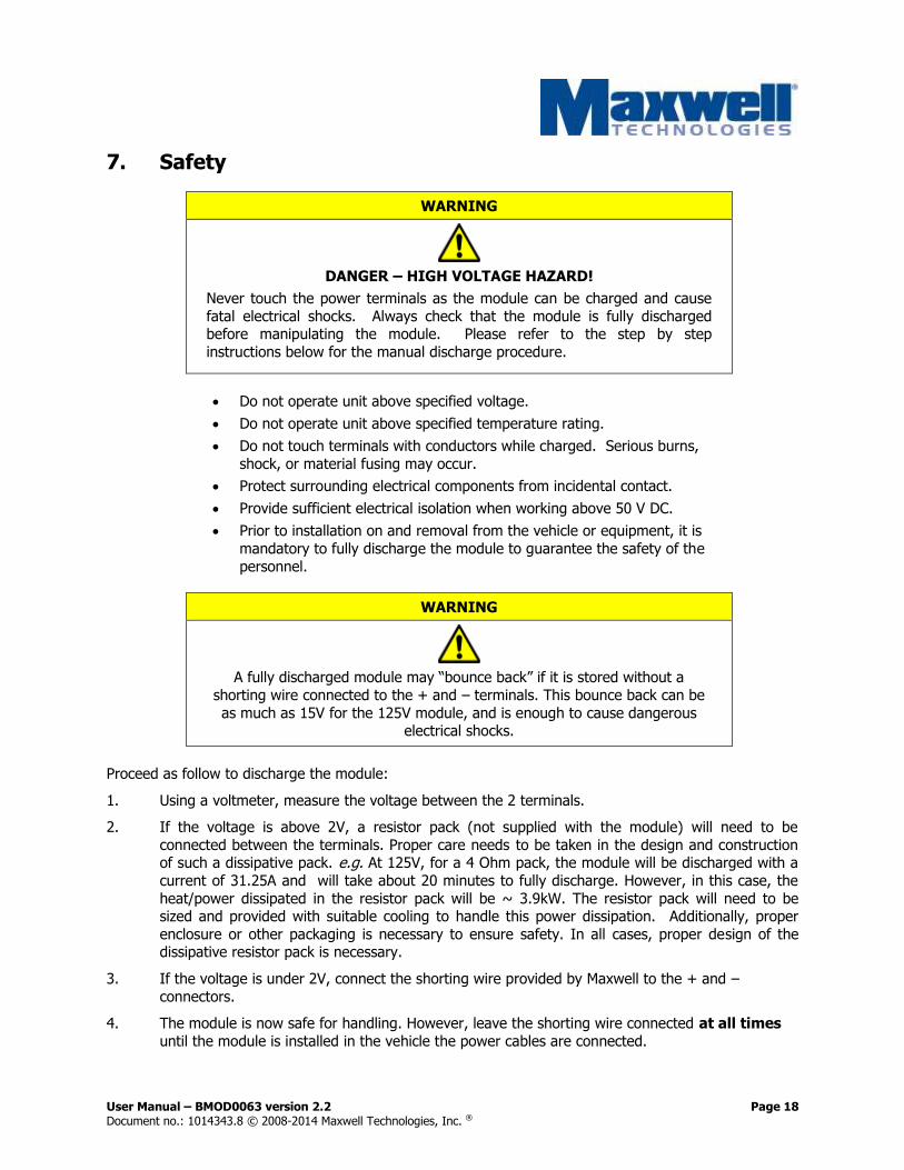
7. Safety
WARNING
DANGER – HIGH VOLTAGE HAZARD!
Never touch the power terminals as the module can be charged and cause
fatal electrical shocks. Always check that the module is fully discharged before manipulating the module. Please refer to the step by step
instructions below for the manual discharge procedure.
Do not operate unit above specified voltage.
Do not operate unit above specified temperature rating.
Do not touch terminals with conductors while charged. Serious burns,
shock, or material fusing may occur.
Protect surrounding electrical components from incidental contact.
Provide sufficient electrical isolation when working above 50 V DC.
Prior to installation on and removal from the vehicle or equipment, it is
mandatory to fully discharge the module to guarantee the safety of the
personnel.
WARNING
A fully discharged module may “bounce back” if it is stored without a
shorting wire connected to the + and – terminals. This bounce back can be
as much as 15V for the 125V module, and is enough to cause dangerous electrical shocks.
Proceed as follow to discharge the module:
1. Using a voltmeter, measure the voltage between the 2 terminals.
2. If the voltage is above 2V, a resistor pack (not supplied with the module) will need to be
connected between the terminals. Proper care needs to be taken in the design and construction of such a dissipative pack. e.g. At 125V, for a 4 Ohm pack, the module will be discharged with a
current of 31.25A and will take about 20 minutes to fully discharge. However, in this case, the
heat/power dissipated in the resistor pack will be ~ 3.9kW. The resistor pack will need to be sized and provided with suitable cooling to handle this power dissipation. Additionally, proper
enclosure or other packaging is necessary to ensure safety. In all cases, proper design of the dissipative resistor pack is necessary.
3. If the voltage is under 2V, connect the shorting wire provided by Maxwell to the + and –
connectors.
4. The module is now safe for handling. However, leave the shorting wire connected at all times
until the module is installed in the vehicle the power cables are connected.

User Manual – BMOD0063 version 2.2 Page 19 Document no.: 1014343.8 © 2008-2014 Maxwell Technologies, Inc. ®
8. Maintenance
Prior to removal from the vehicle, cable removal, or any other handling ensure that the energy storage module is completely discharged in a safe manner. The stored energy and the voltage levels may be
lethal if mishandling occurs. Maintenance should only be conducted by trained personnel on discharged
modules (Paragraph 7).
8.1. Routine Maintenance
8.1.1. Clean exterior surface of dirt/grime 8.1.1.1. Reason - Improve power dissipation performance.
8.1.1.2. Use a cleaning cloth dampened with a water/soap solution. Do not use high-pressure
sprays or immersion 8.1.1.3. Frequency
8.1.1.3.1. Outside use (6 months, or as needed) 8.1.1.3.2. Inside use (annually)
8.1.2. Recondition cell voltage balance per Paragraph 3.2.2.3 8.1.2.1. Reason - Balance cell voltages for longer life
8.1.2.2. Upon overvoltage alarm
8.1.2.3. Upon conditions specified in Paragraph 3. 8.1.3. Check mounting fasteners for proper torque
8.1.3.1. Reason - Avoid mechanical damage 8.1.3.2. Frequency
8.1.3.2.1. High Vibration Environments (6 months)
8.1.3.2.2. Low Vibration Environments (12 months) 8.1.4. Inspect housing for signs of damage
8.1.4.1. Reason – allows potential internal damage to be identified 8.1.4.2. Frequency
8.1.4.2.1. Outside use (6 months, or as needed) 8.1.4.2.2. Inside use (annually)
8.1.5. Check signal/ground connections
8.1.5.1. Reason – avoid false signals or shock hazards 8.1.5.2. Frequency
8.1.5.2.1. High Vibration Environments (6 months) 8.1.5.2.2. Low Vibration Environments (12 months)
8.2. Fan Maintenance and Life Estimation
The 125 V module uses Orion fans - model OD172SAP-24HBXC-55 (24 V) or OD172SAP-12HBXC-55 (12 V). The expected life of the fans (based on L10 life) is 65,000 hours at 45°. L10 life is defined as the
time when 10% of the sample could be expected to fail. The customer is responsible for monitoring fan operation. It is recommended to monitor cell temperature as an indication of fan performance. Damage
to cells as a result of fan failure is not covered under warranty.
8.3. Module Conditioning
Please refer to section 3.2.2.2.
9. Storage
The module can be stored in the original package discharged in a dry place. Observe the maximum
storage temperature as stated in the specifications. Discharge used module prior to stock or shipment.
The shorting wire shipped with the unit should be retained for use during storage to prevent charge from
User Manual – BMOD0063 version 2.2 Page 20 Document no.: 1014343.8 © 2008-2014 Maxwell Technologies, Inc. ®
accumulating in the module.
10. Disposal
Do not dispose of module in trash. Dispose of according to local regulations for flammable materials.
11. Specifications
Refer to data sheets for specifications for each specific product.

Maxwell Technologies, Inc. Global Headquarters 3888 Calle Fortunada San Diego, CA 92123 USA Phone: +1 858 503 3300 Fax: +1 858 503 3301
Maxwell Technologies SA Route de Montena 65 CH-1728 Rossens Switzerland Phone: +41 (0)26 411 85 00 Fax: +41 (0)26 411 85 05
Maxwell Technologies GmbH Leopoldstrasse 244 80807 München Germany Phone: +49 (0)89 4161403 0 Fax: +49 (0)89 4161403 99
Maxwell Technologies Korea Co., Ltd. Room 1524, D-Cube City
Office Tower, 15F #662
Gyeongin-Ro, Guro-Gu,
Seoul, 152-706
South Korea
Phone: +82 10 4518 9829
Maxwell Technologies Shanghai Trading Co., Ltd. Unit A2,C 12th Floor
Huarun Times Square
500 Zhangyang Road,
Pudong New Area
Shanghai 200122,
P.R. China
Phone: +86 21 3852 4000
Fax: +86 21 3852 4099
Maxwell Technologies Shanghai Representative Office Unit B 12th Floor
Huarun Times Square
500 Zhangyang Road,
Pudong New Area
Shanghai 200122,
P.R. China
Phone: +86 21 3852 4000
Fax: +86 21 3852 4099
www.maxwell.com
User Manual – BMOD0063 version 2.3 Document no.: 1014343.8 © 2008-2014 Maxwell Technologies, Inc. ®