Embed Size (px)
Citation preview
1LokSound2 User Manual V1.0 01/2002
User Manual
LokSound2Version 1.0
January 2002

2 LokSound2 User Manual V1.0 01/2002
Contents
1. Introduction .............................................................................................................................................. 32. Characteristics of the LokSound2 decoder .................................................................................................. 33. Connection of the LokSound2 decoders ..................................................................................................... 43.1 Preparing installation of the decoder ........................................................................................................ 43.2 Locomotives with NEM interface ............................................................................................................. 53.3 Locomotives without DCC Interface ......................................................................................................... 53.3.1 Connecting DC motors ......................................................................................................................... 53.3.2 Connecting a universal motor ............................................................................................................... 73.4 Connecting the speaker ........................................................................................................................... 73.5 Connecting the auxiliary functions ........................................................................................................... 73.6 Connecting a wheel sensor ....................................................................................................................... 84. Set Up and installation of the decoder ........................................................................................................ 84.1 Analogue operation ................................................................................................................................. 94.1.1 DC Operation ....................................................................................................................................... 94.1.2 AC operation with conventional Märklin® controller ............................................................................. 94.2 Digital operation ...................................................................................................................................... 94.2.1 Using Märklin® 6021 ........................................................................................................................... 94.2.2 With DCC (Lenz, Intellibox, etc) ............................................................................................................. 95. Adjusting decoder parameters ................................................................................................................. 105.1 CVs of the LokSound2 decoders ............................................................................................................ 105.2 Important settings of LokSound2 .......................................................................................................... 105.2.1 Back EMF control (load control) .......................................................................................................... 105.2.2 Speed Curve ....................................................................................................................................... 115.2.3 Function outputs ................................................................................................................................ 125.2.4 Sound adaptation ............................................................................................................................... 135.2.5 Brake sections ..................................................................................................................................... 155.3 Adjusting CVs ........................................................................................................................................ 165.3.1 Using LokProgrammer ........................................................................................................................ 165.3.2 Using DCC systems .............................................................................................................................. 165.3.3 Using Märklin® 6021 ......................................................................................................................... 166. Frequently asked questions (FAQ) ............................................................................................................. 187. Appendix ................................................................................................................................................. 187.1 List of all supported CVs ........................................................................................................................ 187.2 Technical data ........................................................................................................................................ 308. Service-Support and assistance ................................................................................................................. 30
Copyright 2001 by ESU electronic solutions Ulm GmbH. Electrical characteristics and dimensions are subject tochange without prior notice. All rights reserved. ESU may not be held responsible for any damage or consequentialloss or damage caused by inappropriate use of the product, abnormal operating conditions, unauthorizedmodifications to the product, etc.
Not suitable for children under 3 years of age. Inappropriate use may result in injury due to sharp points andedges.
Maerklin® is a registered trademark of the company Gebr. Maerklin® und Cie. GmbH, Goeppingen, Germany.

3LokSound2 User Manual V1.0 01/2002
1. Introduction
Congratulations on your acquisition of a LokSound2decoder. With LokSound2 your locomotives may finallysound like the prototype. You will soon notice thatyour LokSound2 equipped vehicles will become thecenter of attraction.
Of course, you would like to install this decoder inyour locomotive immediately, but first a request:
Please read this manual carefully before carryingout the installation!!! Although LokSound2decoders are very robust, incorrect connectionmay destroy the module!
Important Warning:
LokSound2 decoders are designed for use inmodel railways only
Avoid mechanical force and impact on thedecoder
Do not expose to wet and humid conditions
Don't remove the heat shrink sleeve on thedecoder
Never solder on the circuit board, extend cablesif necessary
Never wrap the decoder in insulation tape, sincethis may cause overheating
Always disconnect the circuit when installing thedecoder
Make sure that neither the LokSound decodernor any blank wire ends may come into contactwith the locomotive (a risk of short circuit). Co-ver any blank ends of unused wires.
Make sure that no wires are squeezed or cut bythe model's transmission parts when reassemblingthe locomotive.
Handle the speaker with extreme care: Do nottouch the membrane or apply pressure! Solderspeaker connections quickly and only at theintended places! Pay close attention to theinstructions for installing the speaker as outlinedin this manual!
If you adhere to these warnings you will be rewardedby long life and trouble-free operation of yourLokSound2 decoder.
ESU electronic solutions ulm GmbH, January 2002
This manual has several chapters. Chapter 2 is anoverview of the characteristics of LokSound2 decoder.Chapter 3 is about installing and connecting. Chapter4 deals with operational functions of the LokSound2decoder. This chapter provides information howprogramming parameters must be modified in orderto get certain functions. The fifths chapter is abouterror analysis and gives answers to frequently askedquestions. The appendix however includes a detailedlist of all programming parameters as well as technicaldata. For every paragraph in chapter 3 (installing,connecting) there is a corresponding paragraph inchapter 4, which gives advice on programming.
2. Characteristics of the LokSound2 decoder
The LokSound2 decoder is a universal electronicmodule for installation in model locomotives of gaugesTT, H0 and 0. LokSound2 is the improved version ofLokSound and combines two components that hadto be acquired separately in the past:
A full-feature digital decoder with outstandingcharacteristics:
Multi-protocol operation: LokSound2 decoderunderstand both, the common Märklin® /Motorola® - format and the format of NMRA/DCC-system. Thus LokSound2 may be used withalmost all presently available modern digital systems.LokSound2 was tested among others with:
Arnold Digital (DCC operation) Lenz Digital Plus, ROCO digital is cool Märklin® 6021 Uhlenbrock Intellibox (DCC+Motorola® ) ZIMO MX-1 (DCC-operation)
The change over between protocols during operationhappens automatically.
Universal motor connection: All types of motorsmay be attached to the LokSound module:
Direct current motors (e.g. Bühler, Mabuchi) Coreless motors (e.g. Faulhaber, Maxxon) Alternating current motors
High motor pulse frequency: By using a pulsefrequency of 22 kHz (!) the motor is operated verycarefully. Thus the motor is not only quiet (no motorwhine), but also heat generation is minimized andmotor life is enhanced. Even coreless motors maybe operated with the LokSound2 decoder withoutproblem.
Motor regulation: LokSound2 offers secondgeneration load control for direct current motorsand coreless motors. It may be adjusted to the each
Introduction

4 LokSound2 User Manual V1.0 01/2002
individual motor. Your locomotive will always keepthe selected speed, no matter how large the load isor whether it is traveling up or down gradients.
Three function outputs: In addition to the twolighting outputs, another function output is availablefor your choice of operation: you may switch onsmoke generators or interior lighting or uncoupletrains by pressing a key at your central processingunit! With blinking light effects and individuallydimmable lamps your trains look real and give you alot of enjoyment.
Brake tracks: LokSound2 decoders understand (andreact to) all available brake systems: besides the Lenzbrake generator, Märklin® brake track is supportedtoo.
Protecting functions: the motor output as well asall function outputs are protected against overloads.
Please make sure that you adhere to the maximumpermitted current for the function outputs andavoid short circuits between the outputs: theLokSound2 is protected. In case of overload theoutputs will be destroyed.
Analogue operation: LokSound2 decoders may beoperated on AC- and DC systems without problems.
Easy programming: Even with Märklin® 6021 allfunctions may be changed easily without openingthe locomotive.
A digital, two-tone sound module with uniquecharacteristics:
Prototype sounds: sounds of prototype loco-motives were sampled using high qualitymicrophones and recorded digitally onto a memorymodule. Thus your locomotives sound as accurateas the prototype!
Two channels: in addition to steam impact or dieselsounds, a further sound may be generated at thesame time. Steam whistles, bells, horns, etc. willsound just like the original.
Steam, diesel and electric locomotive sounds arepossible: LokSound2 may imitate every type oflocomotive you may think of. For each type oflocomotive there is a prototypical operationalsequence:
Steam locomotive: There are two, three and four-cylinder steam locomotives, whose steam impactsincrease in frequency as the speed of the modellocomotive increases!
Diesel locomotive: The engine may be turned onand off and rotates while stationary or driving basedupon the speed of the locomotive! The LokSound2
Characteristics of the LokSound2 decoder
decoder may now also support Diesel electriclocomotives.
E-Locomotives: Historical electric locomotivessupply sound effects that are well worth listeningto: from the motion of the pantograph to theclicking and cracking of the switchgear duringacceleration! Even a wheel synchronized squeakingof the brakes is possible!
Sounds by pressing a key: Pressing a function key(F1 to F12) emits the sounds!
Random noises: Both while stationary and whilemoving, sounds such as air pump, water pump,coal shovels, compressed air discharging, etc. atrandom intervals controlled by you.
Chapter 3
Connection of the LokSound2 decoders
3.1 Preparing installation of the decoder
The locomotive must be tested for excellent operation:only a locomotive with impeccable mechanicalperformance may take maximum advantage of thedecoder. A locomotive that does not performsmoothly will not operate satisfactorily even with thebest decoder. Replace or clean worn out motor brushes,check wheel contacts, bulbs etc.Remove the locomotive from the track, disconnectand isolate the motor. There must be NO electricalcontact between the motor and the rail pickup.The LokSound2 decoder has fixed dimensions; makesure, that the decoder fits easily into the locomotive.Do not use any pressure when replacing the outerbody onto the frame and touch no wires. Further,make certain that flexible parts such as transmissionsand trucks are not obstructed by wires.
The decoder gets very warm during operation. Neverpack the LokSound2 decoder in foam material. Thisimpedes air circulation and causes overheating.
Electronic components are sensitive toelectrostatic loads: always make sure that yourwork place is grounded. If necessary, use anearthed wristband.
When installing the decoder you must not allowany metal part of the locomotive to touch thesurface components of the decoder.
5LokSound2 User Manual V1.0 01/2002
Locomotives with DCC interface
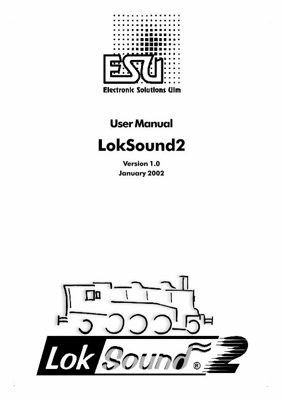
3.2 Locomotives with NEM interface
The LokSound2 decoder comes with a NEM650/652(NMRA S9.1/9.2) digital connector (see fig. 1). Theinstallation is therefore particularly easy:
Remove the body shell. Follow the instructions inthe locomotive manual!
Remove the connector plate or directional relaythat is supplied with the locomotive. Please keepthe plug / relay for future use.
Insert the connector plug with pin 1 (the side withthe red/orange wire) into the side of the connectorwhich is usually marked with *, +, or 1 . Takecare not to bend any pins. Do not rely on theassumption that the wires have to lead in a certaindirection the marking is the only valid reference.
Place the decoder in a suitable location within thelocomotive and fasten it with double sided tape ora drop of glue.
Now fix the speaker in a suitable place. See chapter3.4 for details
3.3 Locomotives without DCC Interface
Not every locomotive has a digital connector and thewiring becomes more elaborate:
Disconnect existing wires within the locomotive andany connection to the chassis. Both motor contactsmust be isolated, make sure there isn't any connectionto the chassis, the wheels or the pantographs. Thismay easily be overlooked particularly in Fleischmannmodels.
Please check all connections with an ohmmeter,particularly if there are any short circuits betweenmotor- and current pick-ups.
How to proceed depends very much on how the lightand special functions are wired in the locomotive.
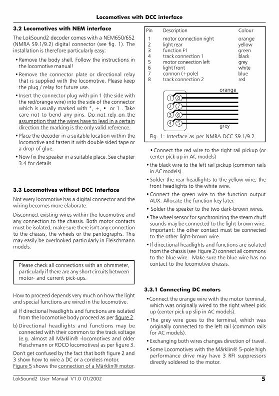
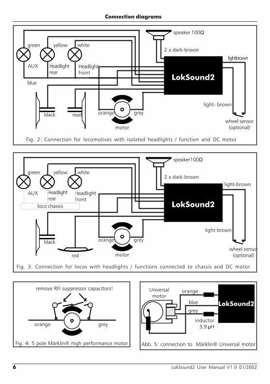
a) If directional headlights and functions are isolatedfrom the locomotive body proceed as per figure 2.
b) Directional headlights and functions may beconnected with their common to the track voltage(e.g. almost all Märklin® -locomotives and olderFleischmann or ROCO locomotives) as per figure 3.
Don't get confused by the fact that both figure 2 and3 show how to wire a DC or a coreless motor.Figure 5 shows the connection of a Märklin® motor.
Pin Description Colour
1 motor connection right orange2 light rear yellow3 function F1 green4 track connection 1 black5 motor coneection left grey6 light front white7 connon (+pole) blue8 track connection 2 red
Fig. 1: Interface as per NMRA DCC S9.1/9.2
1
2
3
4
8
7
6
5
orange
grey
Connect the red wire to the right rail pickup (orcenter pick up in AC models)
the black wire to the left rail pickup (common railsin AC models).
Solder the rear headlights to the yellow wire, thefront headlights to the white wire.
Connect the green wire to the function outputAUX. Allocate the function key later.
Solder the speaker to the two dark-brown wires.
The wheel sensor for synchronizing the steam chuffsounds may be connected to the light-brown wire.Important: the other contact must be connectedto the other light-brown wire.
If directional headlights and functions are isolatedfrom the chassis (see figure 2) connect all commonsto the blue wire. Make sure the blue wire has nocontact to the locomotive chassis.
3.3.1 Connecting DC motors
Connect the orange wire with the motor terminal,which was originally wired to the right wheel pickup (center pick up slip in AC models).
The grey wire goes to the terminal, which wasoriginally connected to the left rail (common railsfor AC models).
Exchanging both wires changes direction of travel.
Some Locomotives with the Märklin® 5-pole highperformance drive may have 3 RFI suppressorsdirectly soldered to the motor.
6 LokSound2 User Manual V1.0 01/2002
Connection diagrams
Fig. 4: 5 pole Märklin® high performance motor
greyorange
remove RFI suppressor capacitors!
green
AUX
LokSound2
yellow white
Headlightrear
Headlightfront
greyorange
motor
Fig. 3: Connection for locos with headlights / functions connected to chassis and DC motor
2 x dark-brown
speaker100Ω
light-brown
wheel sensor(optional)
light-brown
red
black
loco chassis
green
AUX
LokSound2
yellow white
Headlightrear
Headlightfront
greyorange
motor
black read
blue
Fig. 2: Connection for locomotives with isolated headlights / function and DC motor
2 x dark-brwon
speaker 100Ω
lightbrown
wheel sensor(optional)
light- brown
LokSound2grey
orange
blue
Universalmotor
Abb. 5: connection to Märklin® Universal motor
inductor3,9 µH

7LokSound2 User Manual V1.0 01/2002
Connecting a universal motor / speaker / auxiliary functions
The two suppressors that connect the motorterminals with the motor chassis must be removed(see figure 4).
3.3.2 Connecting a universal motor
Figure 5 shows how a universal motor (e.g. AC motorby Märklin®) is connected to the LokSound2 decoder:
Connect the orange wire with the motor terminalthat was originally connected with the center pickup.
Connect the grey wire to the motor terminal thatwas originally connected to the common / wheelpick up.
Exchanging both wires will change direction oftravel.
Solder 2 inductivities with at least 3,9 µH to themotor terminals. You may order these as spare partsfrom Maerklin® under article number 516520.
The RFI suppression inductor remains attached tothe collector terminal of the motor and has to besoldered to the blue wire.
For optimal operation the motor PWM frequencyhas to be reduced from 22kHz to 87Hz. To achievethis set CV 9 to value 204 (see chapter 5).
Please note:If a universal motor is connected, Back EMF Controlwill be automatically deactivated. The principle of BackEMF Control does not work with universal motors.
3.4 Connecting the speaker
The LokSound 2 decoder may only be used with thespeakers offered by ESU electronic solutions ulmGmbH. They have an impedance of 100 Ohm. Theuse of speakers by others may cause considerabledistortion and in extreme cases even destroy theLokSound2 decoder.
The correct position of the speaker is crucial to achievehigh quality sound. A speaker that is installed withouta resonance chamber will not generate good sound.Therefore carefully select the location and soundchamber for the speaker.
The speaker must be installed in such a way that thesound waves are not unduly blocked.
Please handle speakers with extreme care: don'tput pressure on or touch the membrane. Thespeaker's magnets are very strong. Keep all metalitems away and secure the speaker firmly whensoldering. The soldering iron may pull the speakerdue the magnetic field and destroy it.
Connect the speaker to the 2dark brown wires of theLokSound module. Make surethat you use a small solderingiron (max. 20 W) and only heatthe marked spot as shown inthe figure (close to the edge ofthe small contact plate).Polarity is not important.
An optimal sound effect is achieved by putting thespeaker into a sound chamber.
A sound chamber is supplied with each speaker.
This will increase the soundpressure and channel thedirection of the sound.Without sound chamber thesound effect may beunsatisfactory. Feed the
speaker wires througha small hole in thesound chamber.
3.5 Connecting the auxiliary functions
Any load may be connected to the light and functionoutputs as long as it doesn't exceed the maximumcurrent (see technical data in the appendix of thismanual). Note that the overload protection of thedecoder reacts quickly and will switch off all functionsimmediately in case of an overload or short circuit.
Therefore use only 16 V bulbs or higher and amaximum nominal current of 50mA:Incandescent lamps have a high starting currentand this may activate the overload protection ofthe decoder when bulbs are switched on.
Use only digital smoke generators (e.g. Seuthe No.11) for locomotives whose light and function outputsare connected as shown in figure 2. All other smokegenerators require too much current. There are smokegenerators with more than 250mA nominal current.
solder here
speaker
sound chamber

8 LokSound2 User Manual V1.0 01/2002
Locomotives that are connected as shown in figure 3needs an analogue smoke generator e.g. SeutheNo. 10.
Make sure that the sum of all currents for thefunction outputs does not exceed the permittedcurrent rating and avoid short circuits betweenoutputs. Although outputs of LokSound2decoders are protected high voltage on theterminals or a short circuit may cause damage.
3.6 Connecting a wheel sensor
To synchronize the steam chuff an external sensormay (but does not have to be) used. The sensor inputis the light brown wire on the LokSound2 decoder.
The LokSound2 decoder supports reed switches ormechanical contacts.
If a reed switch is to be used a miniature magnet(available at specialized hobby shops) must be attachedto the driving wheel axle in such a way that the magnetreleases the reed switch once every turn. Miniaturereed switches have been proven to be very reliable.They may be obtained at any electronic specialist store.
Suitable magnets may be bought at model train shops.(e.g. Mini-track magnets) which might have to beshaped to fit.
All double pole (mechanical) contacts that are isolated(not connected to the chassis) may be used.
Before the wheel sensor can function various CVshave to be programmed. See chapter 5.2.4 onpage ??.
connecting a wheel sensor / Set Up and installation of the decoder
4. Set Up and installation of the decoder
After successful installation you may operate thedecoder.
But first you will find out how to check yourinstallation. In chapter 4.1 you will find instruction ofhow to operate the decoder in analogue mode. Inchapter 4.2 you learn how to operate it with variousdigital systems.
Before changing any decoder settings (e.g. locomotiveaddress, sound volume) we recommend to readchapter 5. There you find out which parameters areavailable and how they may be altered with thecommonly available DCC command centers.
After installation you may test the LokSound2 decoderas follows.
Please inspect all connections carefully using anohmmeter: are there any short circuits betweenthe motor terminals and the wheel pick-ups?Have all connections between motor terminalsand the chassis been isolated? Are bulbsconnected properly and isolated from thechassis? Is the decoder installed safely to avoidcontact with the chassis? Is there sufficient spacearound the LokSound2 decoder to allow forcooling? Could the LokSound 2 decoder or anyof the wires be squeezed when refitting thehousing? May sound emit from the locomotivewithout obstruction?
After you have checked above points you may switchon the power. We strongly recommend to carry outthis initial test on a track section with overloadprotection. Programming tracks of modern digitalsystems offer this protection. Our LokProgrammeralso offers extremely reliable overload protection.
The pre-set locomotive address is 03.
Does the locomotive travel in both directions?
Turn the lights on: are they operating correctly?
If the LokSound2 decoder was built into alocomotive with DCC interface: check if the DCCconnector is plugged in correctly.
Reed switch
dr i v ingaxle Miniature
magnet
LokSound2
light-brown
light-brown
Fig. 6: Connecting a wheel sensor

9LokSound2 User Manual V1.0 01/2002
DC Operation / AC Operation
4.1 Analogue operation
4.1.1 DC Operation
DC operation using a conventional controller is possiblewithout any problems but has one limitation. Thelocomotive will only start moving when the trackvoltage reaches 7 - 8 V. Maximum speed will be reachedwhen turning the controller to the limit. This isabsolutely normal and is due to the minimum voltagethe LokSound2 decoder requires for operation.
As factory default, sound effects cannot be activatedin DC operation.
4.1.2 AC operation withconventional Märklin® controller
Operation with conventional Märklin® controllersworks as usual: speed is controlled by turning theknob.
To change direction the knob has to be turned to theleft beyond the stop position.
Please note:
The locomotive must have completely stoppedbefore changing direction. Never changedirection of a moving locomotive!
Press the knob slightly longer than usual (about0,5 sec) in order to activate the command reliably.
As factory default, sound effects cannot be used withthis type of operation.
4.2 Digital operation
4.2.1 Using Märklin® 6021
The LokSound2 decoder may be used with allMaerklin® products or compatible systems.
The functions F1 to F4 only can only be activated withthe "New Motorola Format". To activate this formatput the DIP switches 1 and 2 of the 6021 to theupper ("On") position.
4.2.2 With DCC (Lenz, Intellibox, etc)
Remove capacitors that may be connected tothe track section (e.g. in ROCO connecting track).They may impede normal operation of thedecoder.
LokSound2 may be operated with any DCC compatiblesystem. However, the DCC protocol has somedrawbacks, one of which happens so frequently thatwe want to mention it right here:
Lights do not work with DCC systems
DCC locomotives may be set for 14, 28 or 128 speedsteps. LokSound 2 provides all 3 alternatives, but thedecoder "needs to know" which number of speed stepshas been set in the DCC controller for this particularaddress.
The DCC command center too has to manage thedesired mode. Not all command stations implementall speed modes: The Intellibox e.g. offers all 3 variants,whereas Lenz Digital plus V2.x only manages 14 or 28speed steps. As from Lenz Digital plus V3.0 all 3variants are available.
The LokSound2 decoder is pre-set to 14speedstep mode.
Thus the DCC command station must be set to 14speed steps. Some command stations may be set tooperate every locomotive with 28 (e.g. ZIMO) or with128 (e.g. Intellibox) speed steps. In other words: thesettings between LokSound2 and command stationmay not match. This leads to the following difficulties:
Lights cannot be switched via F0
Lights turn on and off, and on and off again(depending on the speed step).
This can easily be fixed: Simply set the speed steps ofthe decoders and the command station to the samevalue. There are two ways to do this:
a) Make sure the command station knows that thelocomotive is operated with 14 speed steps. WithIntellibox e.g. you first call up the locomotive withone of the controllers (press "Locomotive"-key, enteraddress, press "Enter") and then press the"Locomotive" and "Menue" keys. Now press andhold the "arrow down" key until the display show"DCC 14 speed steps". After pressing the "enter" keythe locomotive will be operated with 14 speed stepsand the lights work as desired.
For other DCC systems please consult the user manualfor information on how to adjust the speed steps.
b) Set the LokSound2 decoder to the desired mode.Owners of ZIMO command stations may desire tooperate the LokSound2 decoder with 28 speed stepslike all other locomotives. In that case you have tochange a register (CV29) in the LokSound2 decoder(see chapter 5).

10 LokSound2 User Manual V1.0 01/2002
5. Adjusting decoder parameters
Chapter 5 provides information on how to changethe settings of LokSound2 decoders. Please take yourtime to read and understand the occasionallysomewhat complex explanations.After the introduction into the world of decoderparameters (called CVs) in chapter 5.1, you will find allyou want to know about which CVs have effect theproperties of LokSound2 decoders in chapter 5.2.Paragraph 5.3 explains how CVs may be set with variousDCC and also the Maerklin® command stations.
You find a complete list of all CVs in chapter 7.1.
5.1 CVs of the LokSound2 decoders
LokSound2 decoders are compatible with the NRMA/ DCC standard. That means, that all parameters whichchange the properties of LokSound2 decoders, arestored in so called CVs (Configuration Variables).LokSound2 decoders support 121 variables. This largenumber of CVs shows the multitude of possibilitiesavailable with LokSound2 decoders
To manage this large number of settings werecommend the use of our LokProgrammer. WithLokProgrammer all CVs may be programmed withease and comfort by using a PC. Please note that CVsthat are not programmed properly could impede theperformance of the decoder.
All CVs may be programmed without theLokProgrammer by using any DCC system that isNMRA/DCC compatible. Märklin® 6021 is alsosuitable. Chapter 5.3 explains, how it works.
In each CV values from 0 to 255 may be stored. Theproperties of the decoder change depending on thestored value.
If you have a look at the list of CVs in chapter 7.1 youwill notice that most CVs have number values. CV 1for example contains the locomotive address. This mayvary between 1 and 127 (see range of values). Thefactory setting is 3. Please note that not all CVs havefactory settings. Some CV values are different fordifferent sound effects.
Other CVs represent storage locations that managevarious functions at the same time (mostly turn onand off). CVs 29 and 49 are good examples: for theseCVs the value has to be calculated individually,depending on the setting you want:
First you decide which option should to be turned onor off. In the column "value" you find 2 numbers foreach option. The value 0 indicates the option is switched
off, otherwise the value may range from 1 to 32. Addall values of the individual options to get the value ofthe CV.
Example 1: Let's assume, you want to use theIntellibox DCC with 128 speed steps and analoguerecognition should be active (because you wantto control some locos analogue mode). All otheroptions are turned off. CV 29 shows the value 6(0 + 2 + 4 + 0 = 6).
Example2: You want to activate the Märklin®brake module, Back EMF should be activated.You set CV 49 to 3 (1 + 2 + 0 = 3). Werecommend to deactivate analogue recognitionin CV 49, since the Märklin® brake track andanalogue operation should not be activated atthe same time. You set CV 29 to 0 (0 + 0 + 0 +0 ) = 0.
Example3: You want to turn the volume of thedecoder down. Set CV 63 to 1.
5.2 Important settings of LokSound2
Details of the most important CVs may be found inchapter 5.2. Please study these instructions carefullybefore you do any program changes. Carefuldeliberation will help you to find the optimal settingsto achieve the desired effects with your LokSound2decoder.
5.2.1 Back EMF control (load control)
The LokSound2 decoders utilize second generationload control which, when using DC motors, assuresconstant speed independent of the actual load. Loadcontrol was optimized and tested with motors fromROCO, Bachmann (Liliput), BRAWA, Märklin®, LGB,Buehler, Mabuchi.
Load control may be deactivated completely (if sodesired).
Make sure that load control is always turned offwhen using AC motors - no matter what settingsare used. AC motors are not suitable for loadcontrol.
How to switch on load control
Set the first Bit of CV 49. Read out the CV: loadcontrol is deactivated if the value is 0 or 2. To activatejust add 1 to the actual value and enter.
Adjusting decoder parameters
11LokSound2 User Manual V1.0 01/2002
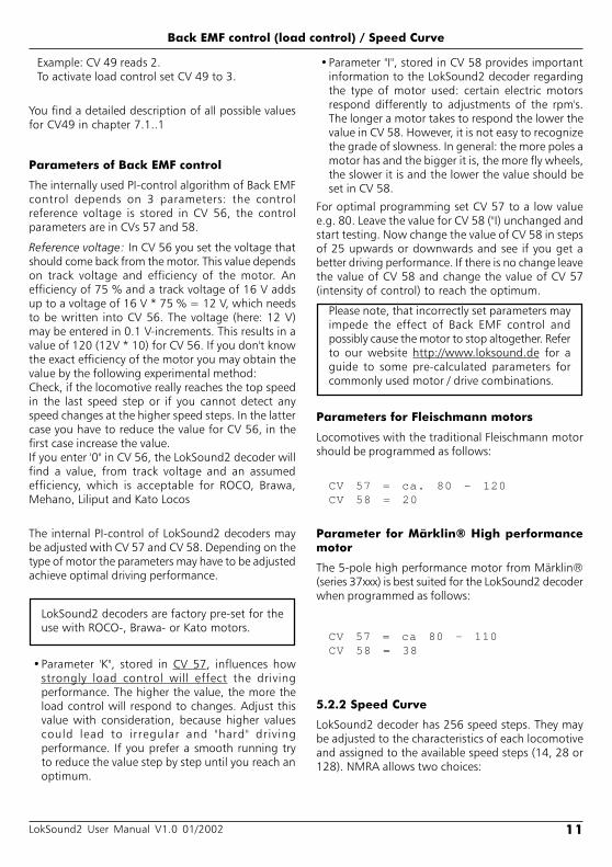
Back EMF control (load control) / Speed Curve
Example: CV 49 reads 2.To activate load control set CV 49 to 3.
You find a detailed description of all possible valuesfor CV49 in chapter 7.1..1
Parameters of Back EMF control
The internally used PI-control algorithm of Back EMFcontrol depends on 3 parameters: the controlreference voltage is stored in CV 56, the controlparameters are in CVs 57 and 58.
Reference voltage: In CV 56 you set the voltage thatshould come back from the motor. This value dependson track voltage and efficiency of the motor. Anefficiency of 75 % and a track voltage of 16 V addsup to a voltage of 16 V * 75 % = 12 V, which needsto be written into CV 56. The voltage (here: 12 V)may be entered in 0.1 V-increments. This results in avalue of 120 (12V * 10) for CV 56. If you don't knowthe exact efficiency of the motor you may obtain thevalue by the following experimental method:Check, if the locomotive really reaches the top speedin the last speed step or if you cannot detect anyspeed changes at the higher speed steps. In the lattercase you have to reduce the value for CV 56, in thefirst case increase the value.If you enter '0" in CV 56, the LokSound2 decoder willfind a value, from track voltage and an assumedefficiency, which is acceptable for ROCO, Brawa,Mehano, Liliput and Kato Locos
The internal PI-control of LokSound2 decoders maybe adjusted with CV 57 and CV 58. Depending on thetype of motor the parameters may have to be adjustedachieve optimal driving performance.
LokSound2 decoders are factory pre-set for theuse with ROCO-, Brawa- or Kato motors.
Parameter 'K", stored in CV 57, influences howstrongly load control will effect the drivingperformance. The higher the value, the more theload control will respond to changes. Adjust thisvalue with consideration, because higher valuescould lead to irregular and "hard" drivingperformance. If you prefer a smooth running tryto reduce the value step by step until you reach anoptimum.
Parameter "I", stored in CV 58 provides importantinformation to the LokSound2 decoder regardingthe type of motor used: certain electric motorsrespond differently to adjustments of the rpm's.The longer a motor takes to respond the lower thevalue in CV 58. However, it is not easy to recognizethe grade of slowness. In general: the more poles amotor has and the bigger it is, the more fly wheels,the slower it is and the lower the value should beset in CV 58.
For optimal programming set CV 57 to a low valuee.g. 80. Leave the value for CV 58 ("I) unchanged andstart testing. Now change the value of CV 58 in stepsof 25 upwards or downwards and see if you get abetter driving performance. If there is no change leavethe value of CV 58 and change the value of CV 57(intensity of control) to reach the optimum.
Please note, that incorrectly set parameters mayimpede the effect of Back EMF control andpossibly cause the motor to stop altogether. Referto our website http://www.loksound.de for aguide to some pre-calculated parameters forcommonly used motor / drive combinations.
Parameters for Fleischmann motors
Locomotives with the traditional Fleischmann motorshould be programmed as follows:
CV 57 = ca. 80 - 120CV 58 = 20
Parameter for Märklin® High performancemotor
The 5-pole high performance motor from Märklin®(series 37xxx) is best suited for the LokSound2 decoderwhen programmed as follows:
CV 57 = ca 80 - 110CV 58 = 38
5.2.2 Speed Curve
LokSound2 decoder has 256 speed steps. They maybe adjusted to the characteristics of each locomotiveand assigned to the available speed steps (14, 28 or128). NMRA allows two choices:

12 LokSound2 User Manual V1.0 01/2002
Speed curve via CV 2, 5 and 6 (figure 7). Set thestarting voltage in CV 2 and the maximum speed withCV 5. CV 6 represents medium speed. You may definethe shape of the curve (straight or with two differentacceleration values). This mode is activated via CV 29(see chapter 7.1).
turns off the acceleration- and deceleration rate andis often used for precise control of the locomotivesparticularly for shunting.
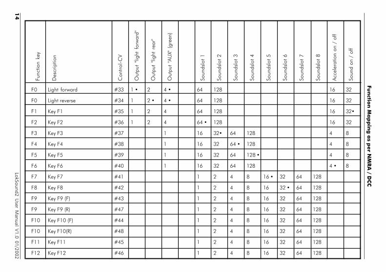
Function key assignment
The outputs may be assigned to the available functionkeys. Each function key is linked to a CV in which anynumber of events may be combined. Figure 9 showsthe different possible combinations and also the ex-factory setting.
Please note:
Some function keys are linked to direction of travel.
Possibly not all function keys are available on yourDCC command station.
Each of the 3 function outputs must be turned onor off separately.
The value that has to be entered into each individualControl-CV is calculated as follows:
Add up the values of those functions that you wantto activate with the corresponding function key. Thenenter this value into the appropriate Control-CV.
Later we look at some examples to highlight theprocess, but first we have to explain two other featuresof the function outputs:
Switching on function outputs
Each of the three function outputs can / must beturned on, before it can be used.
You may program any of three available lighting effectsfor each output:
Dimmer: normal, continuously switched on load
Blinking light: the output blinks with an adjustablefrequency
Blinking light inverse: the output blinks as usualbut in opposite sequence.This permits to activateblinking lights in opposite sequence (lamp 1 = on,while lamp 2 = off and vice versa).
There is a CV (CV 113, 114, 115) for each output, inwhich the desired mode may be stored. Please notethat you may deactivate each output with "0" if notneeded.
The light outputs are factory pre-set to "on". Thisis also true for the AUX output for steamlocomotives, which may be controlled with thelight key.
Function outputs
0 14 28
0
128
256
Fig. 8: Speed curve with CV 67 -90
0
1
2825
6
0 14 28
VMid
VHigh
VStart
Fig. 7: speed curve with CV2, 6, 5
You may also define an individual speed curve: storethe speed curve values in CVs 67 to 94 (as per figure8). Those 28 values will determine the 256 speed steps.This method permits to optimize the drivingperformance. This mode is also activated via CV 29.We recommend the use of the ESU LokProgrammerwith software for easy calculation and programming.
5.2.3 Function outputs
LokSound2 decoder has 3 physical function outputs,two for directional lighting, one for an auxiliary load.
A further 8 "functions" may be activated by pressinga button to trigger various sound effects.
In addition the functions "sound module on / off" and"acceleration on / off" are available. The latter function

13LokSound2 User Manual V1.0 01/2002
Function outputs (lamp brightness, blinking lights)
Dimming of lamps
With LokSound2 you may dim the lamps in 15 stepsto adjust the brightness optimally to your model. Thelamps are pulsed, i.e.: they are continuously switchedon and off. The brightness of each output may beadjusted separately. The desired dimming value (0 to15) has to be added to the value of the correspondingControl-CV (113, 114, 115) that defines the functionmode.
Blinking frequency and duration of "brightphase"
If a function output has been set to "blinking" or"blinking inverse", the duration of the "bright period"(defines blinking frequency) and the on / off ratiohave to be taken from CV 121 (see paragraph 7.1).
The "bright period" is adjustable in 16 steps. It is alwaysa multiple of 0,184 sec.
The On / Off ratio is adjustable in 16 steps from 1/16to 16/16. A ratio of 8/16 indicates that the lightoutput remains "on" for the same period as it is "off".
The value to be entered into the Control-CV 121 iscalculated as follows:Duration of "On" period (value: 0 - 15) * 16 + On /Off ratio
Examples:
Example 1: smoke generator at AUX and F5.Let's assume you want to control a smoke generatorwith function key F5 that should be connected tooutput AUX. Please refer to the installationinstructions in chapter 2.5. The output AUX mustbe activated and assigned to the F5 key:
First we activate the output. In this example wewant to use the dimming function (the output mustbe active continuously) and set at 100% brightness.CV 115 controls output AUX (see paragraph 7.1).
The value to be entered into CV 115 is calculated asfollows: 16 (for dimming function) + 15 (formaximum brightness) = 31.
Now we have to assign function key F5 to outputAUX: see figure 9: Control-CV 39 controls the F5key (third column). In CV 39 we enter thosefunctions that should be switched with the F5-key.We look at the table in figure 9, locate theintersection of the row for F5 and column AUXand find the number (in this case 1). Once we enterthis value in CV 39 the F5key controls the outputAUX.
Example 2: blinking light at AUX and F6.We want to connect a "blinking light" to AUX andcontrol it via the F6 function key. The brightnessshould be set to 6/15 of the maximum value. The"bright period" and the "On / Off" ratio are set asdescribed in paragraph 5.2.3.3.First we have to activate output AUX and set it to"blinking". We achieve this by entering 32 (forblinking) + 5 (= 6/15 of maximum brightness) =37 in CV 115.Next we assign output AUX to the F6 key. We enterthe functions to be controlled via F6 into CV 40.Again we consult the table in figure 9, find theintersection between row F6 and column AUX andenter the number from the table in CV 40 (in thiscase 1). Now the F6 key controls the output AUX.
Example 3: Deceleration on / off with F5Here we want to activate / deactivate theacceleration/deceleration with F5. This functionrepresents a "logical" function and not a "physical"output and thus does not have to be configured.We only have to assign function "deactivatedeceleration" to the F5 key by entering value 4 inCV 39 (see figure 9)
We recommend a PC and LokProgrammer forprogramming function outputs: the Loksound2decoder offers so many possible combinationsthat it is difficult to manage these without acomputer.
5.2.4 Sound adaptation
LokSound2 decoders offer many possibilities to adjustthe sound effects. All parameters are stored in CVsthat, like all others, may be modified.
Adaptation of revolutions for diesel and pitch forsteam
The revolutions of a diesel motor may be modifiedwith 2 CVs:
Enter the revolutions of the idling diesel motor inCV 50. The standard value of 128 permitsreproduction of the sound at original speed, whilevalue 64 reduces this to half speed.
Enter the revolutions at maximum speed in CV 51:value 255 means double the original speed.
Use the same parameters when adapting the pitch ofthe chuffs for steam locomotives: the interval of thechuffs should be shorter and vary in pitch withincreasing speed.
14
LokSound2 User M
anual V1.0 01/2002
Fun
ction
Ma
pp
ing
as p
er N
MR
A / D
CC
Func
tion
key
Des
crip
tion
Con
trol
-CV
Out
put
"ligh
t fo
rwar
d"
Out
put
"ligh
t re
ar"
Out
put
"AU
X" (
gree
n)
Soun
dslo
t 1
Soun
dslo
t 2
Soun
dslo
t 3
Soun
dslo
t 4
Soun
dslo
t 5
Soun
dslo
t 6
Soun
dslo
t 7
Soun
dslo
t 8
Acc
eler
atio
n on
/ o
ff
Soun
d on
/ o
ff
F0 Light forward #33 1 2 4 64 128 16 32
F0 Light reverse #34 1 2 4 64 128 16 32
F1 Key F1 #35 1 2 4 64 128 16 32
F2 Key F2 #36 1 2 4 64 128 16 32
F3 Key F3 #37 1 16 32 64 128 4 8
F4 Key F4 #38 1 16 32 64 128 4 8
F5 Key F5 #39 1 16 32 64 128 4 8
F6 Key F6 #40 1 16 32 64 128 4 8
F7 Key F7 #41 1 2 4 8 16 32 64 128
F8 Key F8 #42 1 2 4 8 16 32 64 128
F9 Key F9 (F) #43 1 2 4 8 16 32 64 128
F9 Key F9 (R) #47 1 2 4 8 16 32 64 128
F10 Key F10 (F) #44 1 2 4 8 16 32 64 128
F10 Key F10(R) #48 1 2 4 8 16 32 64 128
F11 Key F11 #45 1 2 4 8 16 32 64 128
F12 Key F12 #46 1 2 4 8 16 32 64 128
15LokSound2 User Manual V1.0 01/2002
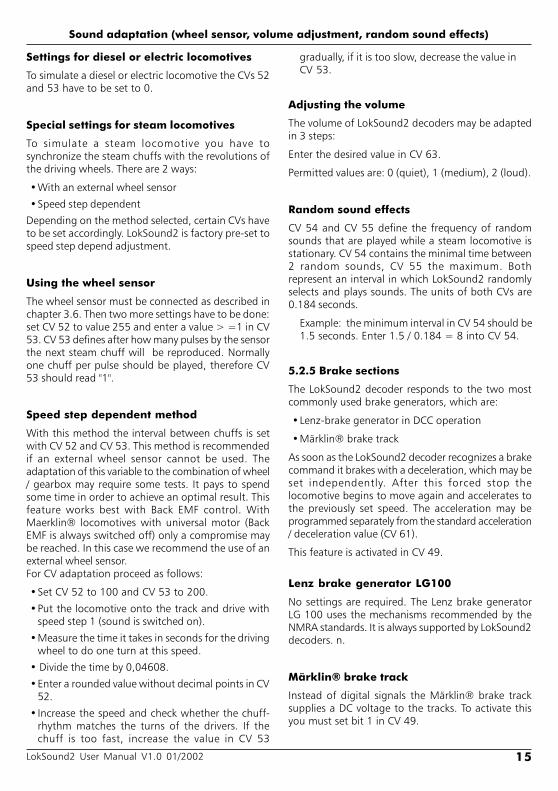
Settings for diesel or electric locomotives
To simulate a diesel or electric locomotive the CVs 52and 53 have to be set to 0.
Special settings for steam locomotives
To simulate a steam locomotive you have tosynchronize the steam chuffs with the revolutions ofthe driving wheels. There are 2 ways:
With an external wheel sensor
Speed step dependent
Depending on the method selected, certain CVs haveto be set accordingly. LokSound2 is factory pre-set tospeed step depend adjustment.
Using the wheel sensor
The wheel sensor must be connected as described inchapter 3.6. Then two more settings have to be done:set CV 52 to value 255 and enter a value > =1 in CV53. CV 53 defines after how many pulses by the sensorthe next steam chuff will be reproduced. Normallyone chuff per pulse should be played, therefore CV53 should read "1".
Speed step dependent method
With this method the interval between chuffs is setwith CV 52 and CV 53. This method is recommendedif an external wheel sensor cannot be used. Theadaptation of this variable to the combination of wheel/ gearbox may require some tests. It pays to spendsome time in order to achieve an optimal result. Thisfeature works best with Back EMF control. WithMaerklin® locomotives with universal motor (BackEMF is always switched off) only a compromise maybe reached. In this case we recommend the use of anexternal wheel sensor.For CV adaptation proceed as follows:
Set CV 52 to 100 and CV 53 to 200.
Put the locomotive onto the track and drive withspeed step 1 (sound is switched on).
Measure the time it takes in seconds for the drivingwheel to do one turn at this speed.
Divide the time by 0,04608.
Enter a rounded value without decimal points in CV52.
Increase the speed and check whether the chuff-rhythm matches the turns of the drivers. If thechuff is too fast, increase the value in CV 53
gradually, if it is too slow, decrease the value inCV 53.
Adjusting the volume
The volume of LokSound2 decoders may be adaptedin 3 steps:
Enter the desired value in CV 63.
Permitted values are: 0 (quiet), 1 (medium), 2 (loud).
Random sound effects
CV 54 and CV 55 define the frequency of randomsounds that are played while a steam locomotive isstationary. CV 54 contains the minimal time between2 random sounds, CV 55 the maximum. Bothrepresent an interval in which LokSound2 randomlyselects and plays sounds. The units of both CVs are0.184 seconds.
Example: the minimum interval in CV 54 should be1.5 seconds. Enter 1.5 / 0.184 = 8 into CV 54.
5.2.5 Brake sections
The LokSound2 decoder responds to the two mostcommonly used brake generators, which are:
Lenz-brake generator in DCC operation
Märklin® brake track
As soon as the LokSound2 decoder recognizes a brakecommand it brakes with a deceleration, which may beset independently. After this forced stop thelocomotive begins to move again and accelerates tothe previously set speed. The acceleration may beprogrammed separately from the standard acceleration/ deceleration value (CV 61).
This feature is activated in CV 49.
Lenz brake generator LG100
No settings are required. The Lenz brake generatorLG 100 uses the mechanisms recommended by theNMRA standards. It is always supported by LokSound2decoders. n.
Märklin® brake track
Instead of digital signals the Märklin® brake tracksupplies a DC voltage to the tracks. To activate thisyou must set bit 1 in CV 49.
Sound adaptation (wheel sensor, volume adjustment, random sound effects)
16 LokSound2 User Manual V1.0 01/2002
Do not activate the Märklin® brake track andthe analogue DC operation at the same time,because the DC of the Märklin® brake track couldbe interpreted as analogue DC operation. WithCV 29 you may switch off the analogue mode(see paragraph 7.1).
5.3 Adjusting CVs
After having been introduced to the effects controlledby CVs in paragraph 5.1 and 5.2 we now need toclarify how to set the CVs. There are 3 possibilities:
With a PC and LokProgrammer
With a DCC compatible digital command station(e.g. Intellibox, Lenz digital plus)
With Märklin® 6021
Depending on the product used the procedure varies.
5.3.1 Using LokProgrammer
The LokProgrammer by ESU electronic solutions ulmGmbH offers the easiest method to modify CVs ofLokSound2 decoders: with a click of the mouse usingMS-Windows®. The PC helps you to find the variousCV numbers and values. With the LokProgrammeryou can also modify the sound effects of LokSound2decoders and you may create your own sound effects.
You may purchase the LokProgrammer at Model Trainoutlets complete with detailed operating instructions.
5.3.2 Using DCC systems
There is no "one fits all" instruction for programmingof CVs with various DCC systems. There are too manydifferences between the popular DCC systems.
Whenever possible you should use the DCC direct mode(CV programming by setting individual bytes withUhlenbrock) or DCC paged mode.
Refer to chapter 9 "programming" of the user manualfor the Intellibox. In particular read chapter 9.5"programming of DCC decoders" very carefully.Programming should be done in the "CV-programmingbyte-wise" mode.
Lenz digital plus
There are various software versions available of theLenz digital plus command station. You need firmwareversion 2.3 or higher in order to program LokSound2
decoders. Contact Lenz for more details regardingupgrades of older versions.
Use "paged CV" mode for programming.Depending on the firmware version the "CVmode" might cause problems.
Older command stations such as "Digital plus", "Lenzcompact" and "Arnold Digital" create anotherphenomenon:
Programming is not possible. The Lenz commandstation displays "err02", the Arnold commandstation "short circuit":
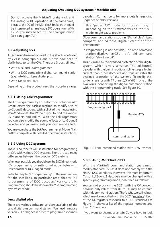
This is caused by the overload protection of the digitalsystem, which is very sensitive. The LokSound2decoder with the built in audio amplifier uses a highercurrent than other decoders and thus activates theoverload protection of the systems. To rectify this,solder a resistor with 47 ohm (0,5 Watt) in one of thetwo wires, connecting the digital command stationwith the programming track. See figure 10.
Adjusting CVs using DCC systems / Märklin 6021
Fig. 10: Lenz command station with 47Ω resistor
Resistor 47Ω
Programming track
command station
5.3.3 Using Märklin® 6021
With the Märklin® command station you cannotmodify standard CVs as it does not comply with theNMRA DCC standards. However, the most importantCVs of LokSound2 decoders may be changed with aspecific programming mode, described as follows:
You cannot program the 6021 with the CV conceptbecause only values from 01 to 80 may be enteredwith this command station. That's why we call values,which may be modified with the 6021 "registers". Eachof the 64 registers responds to a DCC standard CV.Figure 11 shows a list of the register numbers andtheir CV numbers.
If you want to change a certain CV you have to look

17LokSound2 User Manual V1.0 01/2002
Adjusting CVs using Märklin 6021
up the register number first in figure 11 and thenmodify it.Many CVs have three digit values, however, the 6021only allows a two digit input. The LokSound2 decoderovercomes this problem by multiplying the enteredvalue with a factor. The result will be memorizedinternally. See figure 11 for the appropriate multiplier.
That means that not all functions of the LokSound2decoder may be adjusted with Märklin® commandstations.
Programming mode of 6021
Set decoder into programming mode before enteringany changes with the 6021. Only then may the registerbe selected and the new value entered and confirmed.Once you have modified all parameters you want tochange, exit the programming mode with register"80".
Peep sounds, varying in pitch and length, indicatewhich mode you are currently using. That keeps youin control:
Verschieden lange und hohe Töne zeigen die ver-schiedenen Modi des LokSound2-Decoders an:
a) Register input mode (01 to 64 or 80)
(short, low tones, long intervals)b) value input mode (01 to 80)
(combination from long / short tones, high frequency)
c) Confirmation
(long, high tone)
Make sure that not only the track- and motorconnections are installed properly but also the speaker,since the speaker provides the acoustic signals.
The regulator must be set to 0.
Take all other locomotives off the track.
Listen to the sound signals of the locomotive.
To get into programming mode:
Press the "stop" and "go" keys simultaneously on6021 to activate a reset (or pull the plug of thepower pack).
To switch off the track voltage, press the "stop" key.
Enter the current decoder address (alternative "80").
Activate the change of direction feature (turn thecontrol knob far left until you hear a "click"), holdthe knob in position and press the "go"-key.
The Loksound2 decoder is now in register inputmode.
Enter the register number you want to change.Make sure you always enter a two digit number(e.g. "01" and not "1")
To confirm any entry turn the knob far left (changeof direction feature). The decoder is now in valueinput mode.
Now enter a new value for the register as a twodigit number. Bear in mind that this value ismultiplied with the factor given for each register infigure 11.
RegisterCV descr ipt ion mult ip l icator
01 64 Märklin Address 102 2 VStart 103 6 VMid 404 5 VHigh 405 3 Acceleration rate 106 4 Deceleration rate 107 61 Acceleration rate signal section 108 62 Deceleration rate signal section 109 57 Load control parameter K 410 58 Load control parameter I 411 50 Sound Speed Min 412 51 Sound Speed Max 413 52 Sound Steam 1 (chuff) 414 53 Sound Steam 2 (chuff) 41 5 6 3 Volume (Speaker) 116 9 Motor PWM 117 56 Regulation reference 418 11 Packet Time-Out 419 60 Analogue VStart 120 13 Analogue Function status 1 121 14 Analogue Function status 2 122 29 Configuration data 123 49 Control data 124 33 Output location FL(f) 125 34 Output location FL(r) 126 35 Output location F1 127 36 Output location F2 128 37 Output location F3 129 38 Output location F4 130 66 Forward trim 131 95 Reverse trim 160 112 Braking sound Level 161 121 Flash light 162 - 64113-115Output Config Light - AUX 180 End of programming mode
Abb.11: register values for 6021
18 LokSound2 User Manual V1.0 01/2002
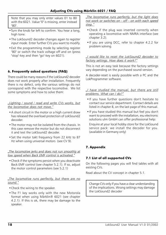
Note that you may only enter values 01 to 80with the 6021. Value "0" is missing, enter instead"80".
Turn the knob far left to confirm. You hear a long,high tone.
The LokSound2 decoder changes again to registerinput mode. Enter further CVs you want to modify.
Exit the programming mode by selecting register"80" or switch the track voltage off and on (press"stop"-key and then "go"-key on 6021).
6. Frequently asked questions (FAQ)
There could be many reasons if the LokSound2 decoderdoes not work properly after installation. Frequentlythere is no defect, only the various settings do notcorrespond with the respective locomotive. We listsome symptoms and how to solve them:
Lighting / sound / read and write CVs works, butthe locomotive does not move.
A short circuit in the motor or a high current drawhas released the overload protection of LokSound2decoder.
The motor may not be isolated from the chassis. Inthis case remove the motor but do not disconnectit and test the LokSound2 decoder.
Set the motor takt frequency from 22 kHz to 87Hz when using universal motors (see CV 9).
The locomotive jerks and does not run smoothly atlow speed when Back EMF control is activated.
Check if the symptoms persist when you deactivateBack EMF control (see chapter 5.2.1). If so, adjustthe motor control parameters (see 5.2.1)
The locomotive runs perfectly, but there are nosound.
Check the wiring to the speaker.
The F1 key works only with the new Motorolaformat when using Märklin® 6021 (see chapter4.2.1). If this is ok, there may be damage to thespeaker.
Adjusting CVs using Märklin 6021 / FAQ
The locomotive runs perfectly, but the light doesnot work or switches on - off - on with each speedstep.
Check if the plug was inserted correctly whenoperating a locomotive with NMRA interface (seechapter 3.2).
If you are using DCC, refer to chapter 4.2.2 forproblem solving.
I would like to reset the LokSound2 decoder tofactory settings. How does it work?
This is not an easy task because the factory settingsvary depending on the purchased sound version.
A decoder-reset is easily possible with a PC and theLokProgrammer software.
I have studied the manual, but there are stillproblems. What can I do?
If you have further questions don't hesitate tocontact our service department. Contact details arelisted in chapter 8, on the last page of this manual.
If you have studied this manual but feel you don'twant to proceed with the installation, esu electronicsolutions ulm GmbH can offer professional help:
Enquire at your local hobby store for the LokSoundservice pack: we install the decoder for you.(available in Germany only)
7. Appendix
7.1 List of all supported CVs
On the following pages you will find tables with allexisting CVs.
Read about the CV concept in chapter 5.1.
Change CVs only if you have a clear understandingof the implications. Wrong settings may damagethe LokSound2 decoder

19LokSound2 User Manual V1.0 01/2002
C V name descr ipt ion range defau l t
1 Locomotive address Address of locomotive 1 - 119 3
2 Start voltage Sets the minimum speed of the locomotive 0 - 255 3
3 Acceleration This value multiplied by 0.869 is the time 0 - 63 4from stop to maximum speed
4 Deceleration This value multiplied by 0.869 is the time 0 - 63 3from maximum speed to stop
5 Maximum speed Maximum speed of locomotive 0 - 255 63
6 Vmid Medium speed of locomotive 0 - 255 25
7 Version number Internal software version of LokSound2 decoder - -
8 Manufacturer's ID Manufacturer's version number (ID) of ESU - 151
9 PWM period Duration of PWM signal for motor control 0, 204 0
function value
PWM frequency = 22000 Hz (recommended) 0PWM frequency = 87 Hz (for universal motors) 204
11 Paket timeout time This value multiplied by 0.36864 is the time 0 - 255 0after which the locomotive stops if no DCC packet isreceived.Switch off with value 0.
13 Analogue mode F1-F8 Status of functions F1 to F8 in analogue mode. 0-255 0
Bit Function Value
0 Function F1 1
1 Function F2 2
2 Function F3 4
3 Function F4 8
4 Function F5 16
5 Function F6 32
6 Function F7 64
7 Function F8 128
14 Analogue mode FL, Status of functions FL, F9 bis F12 in analogue mode. 0-255 3F9-F12
Bit Function Value
0 Function FL(f) 1
1 Function FL(r) 2
2 Function F9(f) 4
3 Function F10(f) 8
4 Function F11 16
5 Function F12 32
6 Function F9(r) 64
7 Function F10(r) 128
List of all supported CVs
20 LokSound2 User Manual V1.0 01/2002
List of all supported CVs
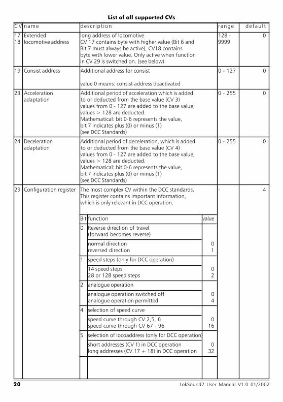
C V name descr ipt ion range defau l t
17 Extended long address of locomotive 128 - 018 locomotive address CV 17 contains byte with higher value (Bit 6 and 9999
Bit 7 must always be active), CV18 containsbyte with lower value. Only active when functionin CV 29 is switched on. (see below)
19 Consist address Additional address for consist 0 - 127 0
value 0 means: consist address deactivated
23 Acceleration Additional period of acceleration which is added 0 - 255 0adaptation to or deducted from the base value (CV 3)
values from 0 - 127 are added to the base value,values > 128 are deducted.Mathematical: bit 0-6 represents the value,bit 7 indicates plus (0) or minus (1)(see DCC Standards)
24 Deceleration Additional period of deceleration, which is added 0 - 255 0adaptation to or deducted from the base value (CV 4)
values from 0 - 127 are added to the base value,values > 128 are deducted.Mathematical: bit 0-6 represents the value,bit 7 indicates plus (0) or minus (1)(see DCC Standards)
29 Configuration register The most complex CV within the DCC standards. - 4This register contains important information,which is only relevant in DCC operation.
Bit function value
0 Reverse direction of travel(forward becomes reverse)
normal direction 0reversed direction 1
1 speed steps (only for DCC operation)
14 speed steps 028 or 128 speed steps 2
2 analogue operation
analogue operation switched off 0analogue operation permitted 4
4 selection of speed curve
speed curve through CV 2,5, 6 0speed curve through CV 67 - 96 16
5 selection of locoaddress (only for DCC operation)
short addresses (CV 1) in DCC operation 0long addresses (CV 17 + 18) in DCC operation 32
21LokSound2 User Manual V1.0 01/2002
List of all supported CVs
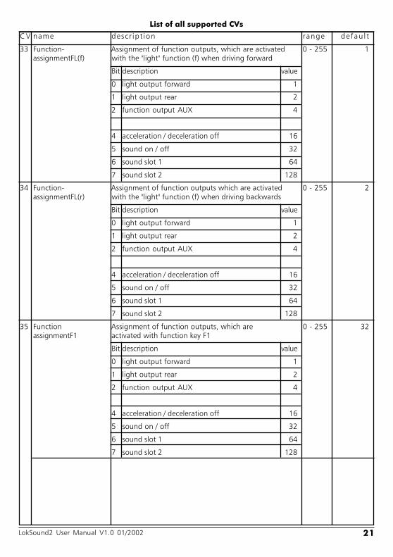
C V name descr ipt ion range defau l t
33 Function- Assignment of function outputs, which are activated 0 - 255 1assignmentFL(f) with the "light" function (f) when driving forward
Bit description value
0 light output forward 1
1 light output rear 2
2 function output AUX 4
4 acceleration / deceleration off 16
5 sound on / off 32
6 sound slot 1 64
7 sound slot 2 128
34 Function- Assignment of function outputs which are activated 0 - 255 2assignmentFL(r) with the "light" function (f) when driving backwards
Bit description value
0 light output forward 1
1 light output rear 2
2 function output AUX 4
4 acceleration / deceleration off 16
5 sound on / off 32
6 sound slot 1 64
7 sound slot 2 128
35 Function Assignment of function outputs, which are 0 - 255 32assignmentF1 activated with function key F1
Bit description value
0 light output forward 1
1 light output rear 2
2 function output AUX 4
4 acceleration / deceleration off 16
5 sound on / off 32
6 sound slot 1 64
7 sound slot 2 128
22 LokSound2 User Manual V1.0 01/2002
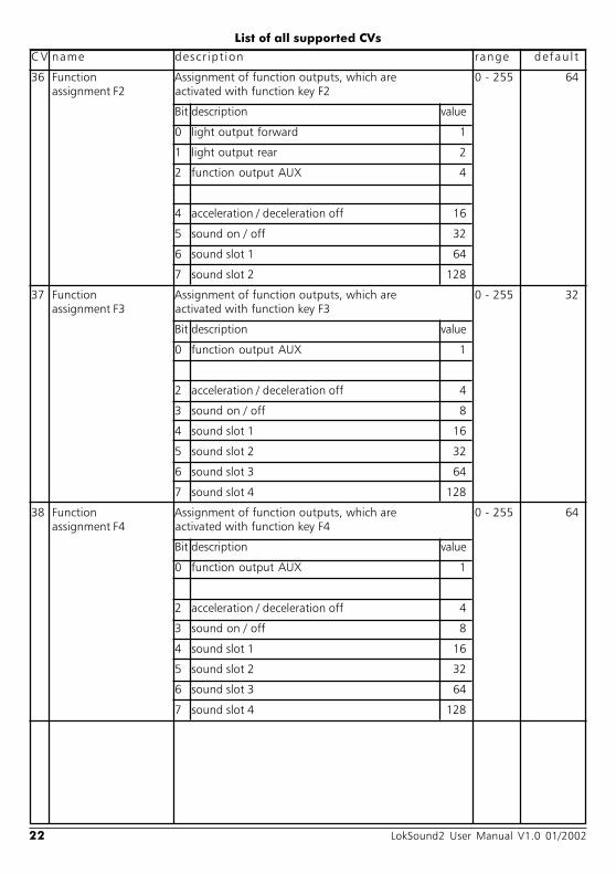
C V name descr ipt ion range defau l t
36 Function Assignment of function outputs, which are 0 - 255 64assignment F2 activated with function key F2
Bit description value
0 light output forward 1
1 light output rear 2
2 function output AUX 4
4 acceleration / deceleration off 16
5 sound on / off 32
6 sound slot 1 64
7 sound slot 2 128
37 Function Assignment of function outputs, which are 0 - 255 32assignment F3 activated with function key F3
Bit description value
0 function output AUX 1
2 acceleration / deceleration off 4
3 sound on / off 8
4 sound slot 1 16
5 sound slot 2 32
6 sound slot 3 64
7 sound slot 4 128
38 Function Assignment of function outputs, which are 0 - 255 64assignment F4 activated with function key F4
Bit description value
0 function output AUX 1
2 acceleration / deceleration off 4
3 sound on / off 8
4 sound slot 1 16
5 sound slot 2 32
6 sound slot 3 64
7 sound slot 4 128
List of all supported CVs

23LokSound2 User Manual V1.0 01/2002
List of all supported CVs
C V name descr ipt ion range defau l t
39 Function Assignment of function outputs, which are 0 - 255 0assignment F5 activated with function key F5
Bit description value
0 function output AUX 1
2 acceleration / deceleration off 4
3 sound on / off 8
4 sound slot 1 16
5 sound slot 2 32
6 sound slot 3 64
7 sound slot 4 128
40 Function Assignment of function outputs, which are 0 - 255 0assignment F6 activated with function key F6
Bit description value
0 function output AUX 1
2 acceleration / deceleration off 4
3 sound on / off 8
4 sound slot 1 16
5 sound slot 2 32
6 sound slot 3 64
7 sound slot 4 128
41 Function Assignment of function outputs, which are 0 - 255 0assignment F7 activated with function key F7
Bit description value
0 sound slot 1 1
1 sound slot 2 2
2 sound slot 3 4
3 sound slot 4 8
4 sound slot 5 16
5 sound slot 6 32
6 sound slot 7 64
7 sound slot 8 128
24 LokSound2 User Manual V1.0 01/2002
C V name descr ipt ion range defau l t
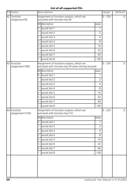
42 Function Assignment of function outputs, which are 0 - 255 0assignment F8 activated with function key F8
Bit description value
0 sound slot 1 1
1 sound slot 2 2
2 sound slot 3 4
3 sound slot 4 8
4 sound slot 5 16
5 sound slot 6 32
6 sound slot 7 64
7 sound slot 8 128
43 Function Assignment of function outputs, which are 0 - 255 0assignment F9(f) activated with function key F9 when driving forward
Bit description value
0 sound slot 1 1
1 sound slot 2 2
2 sound slot 3 4
3 sound slot 4 8
4 sound slot 5 16
5 sound slot 6 32
6 sound slot 7 64
7 sound slot 8 128
44 Function Assignment of function outputs, which are 0 - 255 0assignment F10(f) activated with function key F10
Bit description value
0 sound slot 1 1
1 sound slot 2 2
2 sound slot 3 4
3 sound slot 4 8
4 sound slot 5 16
5 sound slot 6 32
6 sound slot 7 64
7 sound slot 8 128
List of all supported CVs

25LokSound2 User Manual V1.0 01/2002
List of all supported CVs
C V name descr ipt ion range defau l t
45 Function Assignment of function outputs, which are 0 - 255 0assignment F11 activated with function key F11
Bit description value
0 sound slot 1 1
1 sound slot 2 2
2 sound slot 3 4
3 sound slot 4 8
4 sound slot 5 16
5 sound slot 6 32
6 sound slot 7 64
7 sound slot 8 128
46 Function Assignment of function outputs, which are 0 - 255 0assignment F12 activated with function key F12
Bit description value
0 sound slot 1 1
1 sound slot 2 2
2 sound slot 3 4
3 sound slot 4 8
4 sound slot 5 16
5 sound slot 6 32
6 sound slot 7 64
7 sound slot 8 128
47 Function Assignment of function outputs, which are 0 - 255 0assignment F9(r) activated with function key F9 when driving backwards
Bit description value
0 sound slot 1 1
1 sound slot 2 2
2 sound slot 3 4
3 sound slot 4 8
4 sound slot 5 16
5 sound slot 6 32
6 sound slot 7 64
7 sound slot 8 128
26 LokSound2 User Manual V1.0 01/2002
List of all supported CVs
C V name descr ipt ion range defau l t
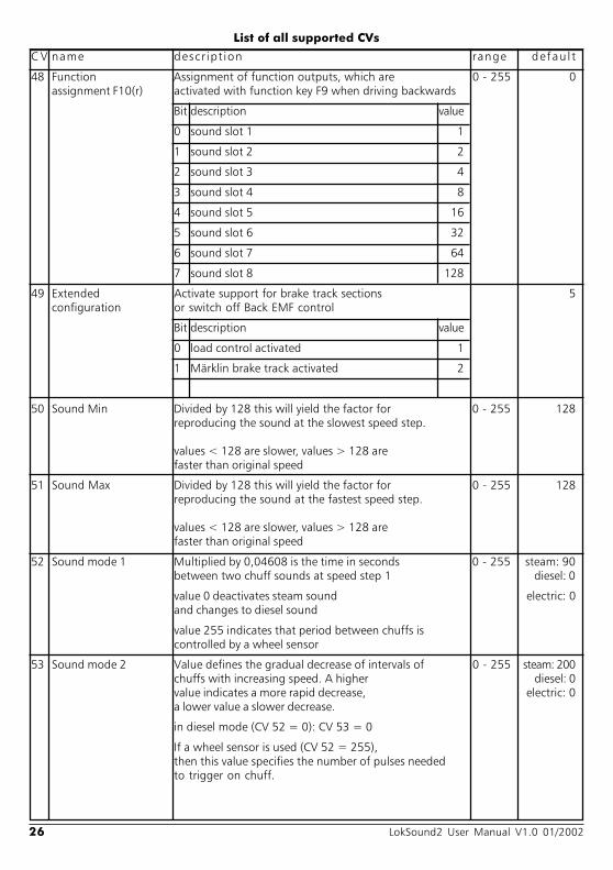
48 Function Assignment of function outputs, which are 0 - 255 0assignment F10(r) activated with function key F9 when driving backwards
Bit description value
0 sound slot 1 1
1 sound slot 2 2
2 sound slot 3 4
3 sound slot 4 8
4 sound slot 5 16
5 sound slot 6 32
6 sound slot 7 64
7 sound slot 8 128
49 Extended Activate support for brake track sections 5configuration or switch off Back EMF control
Bit description value
0 load control activated 1
1 Märklin brake track activated 2
50 Sound Min Divided by 128 this will yield the factor for 0 - 255 128reproducing the sound at the slowest speed step.
values < 128 are slower, values > 128 arefaster than original speed
51 Sound Max Divided by 128 this will yield the factor for 0 - 255 128reproducing the sound at the fastest speed step.
values < 128 are slower, values > 128 arefaster than original speed
52 Sound mode 1 Multiplied by 0,04608 is the time in seconds 0 - 255 steam: 90between two chuff sounds at speed step 1 diesel: 0
value 0 deactivates steam sound electric: 0and changes to diesel sound
value 255 indicates that period between chuffs iscontrolled by a wheel sensor
53 Sound mode 2 Value defines the gradual decrease of intervals of 0 - 255 steam: 200chuffs with increasing speed. A higher diesel: 0value indicates a more rapid decrease, electric: 0a lower value a slower decrease.
in diesel mode (CV 52 = 0): CV 53 = 0
If a wheel sensor is used (CV 52 = 255),then this value specifies the number of pulses neededto trigger on chuff.
27LokSound2 User Manual V1.0 01/2002
List of all supported CVs
C V name descr ipt ion range defau l t
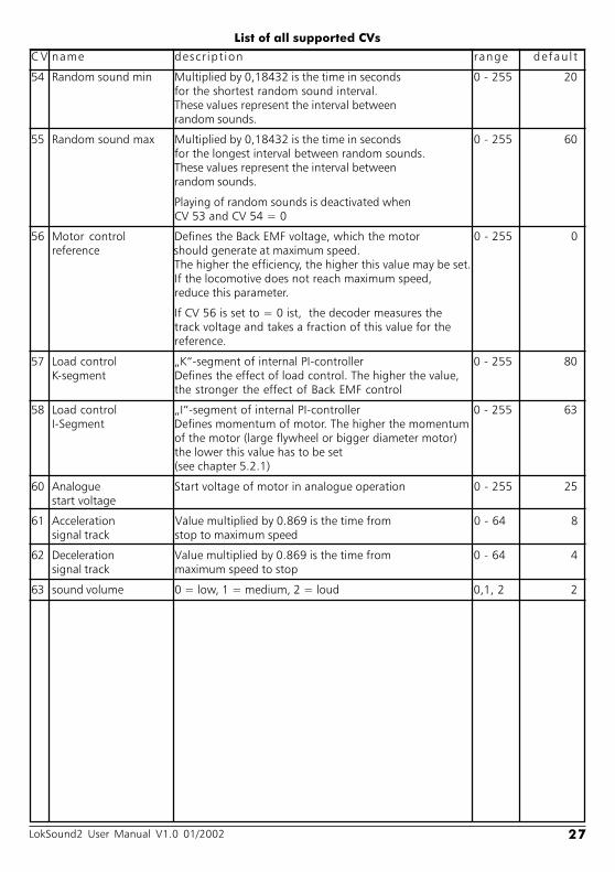
54 Random sound min Multiplied by 0,18432 is the time in seconds 0 - 255 20for the shortest random sound interval.These values represent the interval betweenrandom sounds.
55 Random sound max Multiplied by 0,18432 is the time in seconds 0 - 255 60for the longest interval between random sounds.These values represent the interval betweenrandom sounds.
Playing of random sounds is deactivated whenCV 53 and CV 54 = 0
56 Motor control Defines the Back EMF voltage, which the motor 0 - 255 0reference should generate at maximum speed.
The higher the efficiency, the higher this value may be set.If the locomotive does not reach maximum speed,reduce this parameter.
If CV 56 is set to = 0 ist, the decoder measures thetrack voltage and takes a fraction of this value for thereference.
57 Load control K-segment of internal PI-controller 0 - 255 80K-segment Defines the effect of load control. The higher the value,
the stronger the effect of Back EMF control
58 Load control I-segment of internal PI-controller 0 - 255 63I-Segment Defines momentum of motor. The higher the momentum
of the motor (large flywheel or bigger diameter motor)the lower this value has to be set(see chapter 5.2.1)
60 Analogue Start voltage of motor in analogue operation 0 - 255 25start voltage
61 Acceleration Value multiplied by 0.869 is the time from 0 - 64 8signal track stop to maximum speed
62 Deceleration Value multiplied by 0.869 is the time from 0 - 64 4signal track maximum speed to stop
63 sound volume 0 = low, 1 = medium, 2 = loud 0,1, 2 2

28 LokSound2 User Manual V1.0 01/2002
List of all supported CVs
C V name descr ipt ion range defau l t
64 Märklin® address Address of decoder in Motorola® operation. 0 - 255 12The address is interpreted according to the Motorola®format. The following table shows the values,that have to be entered in CV64 to get thecorresponding Märklin® address
You don't need above table if you want to change theaddress with Märklin® 6021 (see 5.3.3):Enter desired address directly and the decoder will dothe rest.
66 Forward trim Divided by 128 is the factor used to multiply 0 - 255 0the motor voltage when driving forward.
Value 0 deactivates the trim
67- Speed Table Defines motor voltage for speed steps. 0 - 255 ---94 The values "in between" will be interpolated.
95 Reverse trim Divided by 128 is the factor used to multiply 0 - 255 0the motor voltage when driving backwards.
Value 0 deactivates the trim
address value
1 32 13 124 155 136 47 78 59 4810 5111 4912 6013 6314 6115 5216 5517 5318 1619 1920 1721 2822 3123 2924 2025 2326 2127 192
address value
28 19529 19330 20431 20732 20533 19634 19935 19736 24037 24338 24139 25240 25541 25342 24443 24744 24545 20846 21147 20948 22049 22350 22151 21252 21553 21354 64
address value
55 6756 6557 7658 7959 7760 6861 7162 6963 11264 11565 11366 12467 12768 12569 11670 11971 11772 8073 8374 8175 9276 9577 9378 8479 8780 85

29LokSound2 User Manual V1.0 01/2002
List of all supported CVs
C V name descr ipt ion range defau l t
105 User ID Available to the user for any data 0 - 255 0106
112 Brake sound Specifies when the decoder starts the braking noises. 0 - 255 0 / 12threshold The higher the value, the sooner it will start.
If CV 112 = 0, the sound is only played once thelocomotive has stopped.
113 Output configuration Specifies function of output forward light 0 - 255 31forward light
Bit function value
- Output switched off 0
- Output as dimmer (normal) Vol + 16
- Output as blinking light Vol + 32
- Output is blinking light reversed Vol + 48
Add values of brightness (= Vol) to the values above.Permitted values are 0 (very dark) to 15 (very bright)
114 Output configuration Specifies function of output rear light 0 - 255 31rear light
Bit function value
- Output switched off 0
- Output as dimmer (normal) Vol + 16
- Output as blinking light Vol + 32
- Output is blinking light reversed Vol + 48
Add values of brightness (= Vol) to the values above.Permitted values are 0 (very dark) to 15 (very bright)
115 Output configuration Specifies function of output AUX 0 - 255 31AUX
Bit function value
- Output switched off 0
- Output as dimmer (normal) Vol + 16
- Output as blinking light Vol + 32
- Output is blinking light reversed Vol + 48
Add values of brightness (= Vol) to the values above.Permitted values are 0 (very dark) to 15 (very bright)
121 Blinking light Specifies the duration of the "bright period" and the 0 - 255 0on/off ratio of outputs, which are set to blinking
Bit function value
0-3 On / Off ratio 0 - 15
4-7 PWM period time 16 - 240
The PWM period time is a multiple of 0.18432 seconds.
30 LokSound2 User Manual V1.0 01/2002
Technical daten / Service and Support
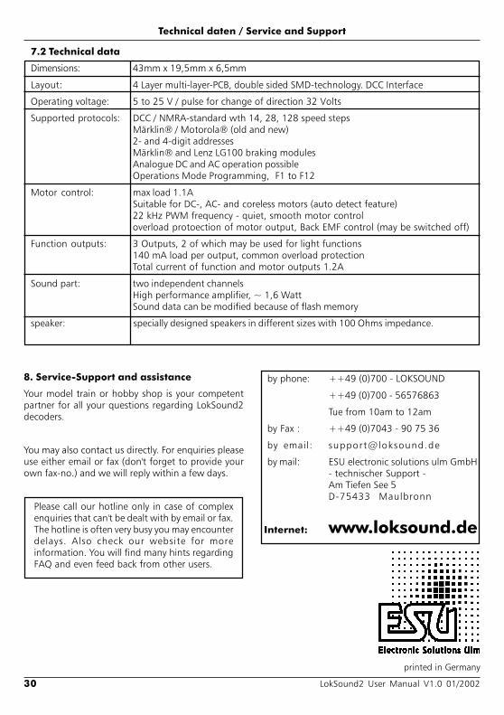
7.2 Technical data
Dimensions: 43mm x 19,5mm x 6,5mm
Layout: 4 Layer multi-layer-PCB, double sided SMD-technology. DCC Interface
Operating voltage: 5 to 25 V / pulse for change of direction 32 Volts
Supported protocols: DCC / NMRA-standard wth 14, 28, 128 speed stepsMärklin® / Motorola® (old and new)2- and 4-digit addressesMärklin® and Lenz LG100 braking modulesAnalogue DC and AC operation possibleOperations Mode Programming, F1 to F12
Motor control: max load 1.1ASuitable for DC-, AC- and coreless motors (auto detect feature)22 kHz PWM frequency - quiet, smooth motor controloverload protoection of motor output, Back EMF control (may be switched off)
Function outputs: 3 Outputs, 2 of which may be used for light functions140 mA load per output, common overload protectionTotal current of function and motor outputs 1.2A
Sound part: two independent channelsHigh performance amplifier, ~ 1,6 WattSound data can be modified because of flash memory
speaker: specially designed speakers in different sizes with 100 Ohms impedance.
8. Service-Support and assistance
Your model train or hobby shop is your competentpartner for all your questions regarding LokSound2decoders.
You may also contact us directly. For enquiries pleaseuse either email or fax (don't forget to provide yourown fax-no.) and we will reply within a few days.
Please call our hotline only in case of complexenquiries that can't be dealt with by email or fax.The hotline is often very busy you may encounterdelays. Also check our website for moreinformation. You will find many hints regardingFAQ and even feed back from other users.
by phone: ++49 (0)700 - LOKSOUND
++49 (0)700 - 56576863
Tue from 10am to 12am
by Fax : ++49 (0)7043 - 90 75 36
by email: [email protected]
by mail: ESU electronic solutions ulm GmbH- technischer Support -Am Tiefen See 5D-75433 Maulbronn
Internet: www.loksound.de
printed in Germany