Embed Size (px)
Citation preview

KRAMER ELECTRONICS LTD.
USER MANUAL
MODEL:
VS-211HA Automatic HDMI Standby Switcher
P/N: 2900-300378 Rev 2


VS-211HA – Contents i
Contents
1 Introduction 1 2 Getting Started 2 2.1 Achieving the Best Performance 2 2.2 Safety Instructions 2 2.3 Recycling Kramer Products 3 3 Overview 4 3.1 Defining the VS-211HA Automatic HDMI Standby Switcher 5 4 Connecting the VS-211HA 6 4.1 Connecting the REMOTE Terminal Block Connector 7 5 Operating the VS-211HA 8 5.1 Using the Manual Mode 8 5.2 Using the Automatic Mode 8 5.3 Using the Override Mode 9 6 Technical Specifications 10
Figures
Figure 1: VS-211HA Automatic HDMI Standby Switcher 5 Figure 2: VS-211HA Connections 7 Figure 3: REMOTE Terminal Block Connector 7

VS-211HA - Introduction 1
1 Introduction
Welcome to Kramer Electronics! Since 1981, Kramer Electronics has been
providing a world of unique, creative, and affordable solutions to the vast range of
problems that confront video, audio, presentation, and broadcasting professionals
on a daily basis. In recent years, we have redesigned and upgraded most of our
line, making the best even better!
Our 1,000-plus different models now appear in 14 groups that are clearly defined
by function: GROUP 1: Distribution Amplifiers; GROUP 2: Switchers and Routers;
GROUP 3: Control Systems; GROUP 4: Format/Standards Converters; GROUP 5:
Range Extenders and Repeaters; GROUP 6: Specialty AV Products; GROUP 7:
Scan Converters and Scalers; GROUP 8: Cables and Connectors; GROUP 9:
Room Connectivity; GROUP 10: Accessories and Rack Adapters; GROUP 11:
Sierra Video Products; GROUP 12: Digital Signage; GROUP 13: Audio; and
GROUP 14: Collaboration.
Congratulations on purchasing your Kramer VS-211HA Automatic HDMI Standby
Switcher, which is ideal for the following typical applications:
Providing backup switching
Boardrooms and meeting rooms
Restaurant and entertainment venues

2 VS-211HA - Getting Started
2 Getting Started
We recommend that you:
Unpack the equipment carefully and save the original box and packaging
materials for possible future shipment
Review the contents of this user manual
Go to http://www.kramerelectronics.com/support/product_downloads.asp
to check for up-to-date user manuals, application programs, and to check if
firmware upgrades are available (where appropriate).
2.1 Achieving the Best Performance
To achieve the best performance:
Use only good quality connection cables (we recommend Kramer high-
performance, high-resolution cables) to avoid interference, deterioration in
signal quality due to poor matching, and elevated noise levels (often
associated with low quality cables)
Do not secure the cables in tight bundles or roll the slack into tight coils
Avoid interference from neighboring electrical appliances that may adversely
influence signal quality
Position your Kramer VS-211HA away from moisture, excessive sunlight and
dust
This equipment is to be used only inside a building. It may only be
connected to other equipment that is installed inside a building.
2.2 Safety Instructions
Caution: There are no operator serviceable parts inside the unit
Warning: Use only the Kramer Electronics input power wall
adapter that is provided with the unit
Warning: Disconnect the power and unplug the unit from the wall
before installing
i
!
!

VS-211HA - Getting Started 3
2.3 Recycling Kramer Products
The Waste Electrical and Electronic Equipment (WEEE) Directive 2002/96/EC
aims to reduce the amount of WEEE sent for disposal to landfill or incineration by
requiring it to be collected and recycled. To comply with the WEEE Directive,
Kramer Electronics has made arrangements with the European Advanced
Recycling Network (EARN) and will cover any costs of treatment, recycling and
recovery of waste Kramer Electronics branded equipment on arrival at the EARN
facility. For details of Kramer’s recycling arrangements in your particular country
go to our recycling pages at http://www.kramerelectronics.com/support/recycling/.

4 VS-211HA - Overview
3 Overview
The VS-211HA is a high-performance automatic standby switcher for HDMI video
and unbalanced stereo audio signals. The VS-211HA can be used as a manual
2x1 switcher or as an automatic switcher. The switcher either uses a priority input
or last connected input.
In priority switching, the signal automatically switches to the secondary input if the
primary signal is lost. If the primary signal reappears, the unit automatically
switches back to the primary input.
In last connected switching, the switcher automatically switches to the newly
introduced input.
In addition, the VS-211HA features:
A maximum data rate of up to 6.75Gbps (2.25Gbps per graphic channel)
HDTV compatibility
HDCP and HDMI compliance
3D pass through
EDID PassThru that passes EDID signals from display to source
DIP-switches for setting the switching mode (manual, auto priority, auto last
connected)
Contact closure remote control for manual operation
Signal auto detect
Parallel unbalanced stereo audio switching
Audio Return Channel (ARC)
No signal on both HDMI inputs triggers the output auto off, to allow displays
to enter sleep mode
Compact DigiTOOLS® size, three units can be rack mounted side-by-side in
a 1U rack space with the optional RK-3T rack adapter

VS-211HA - Overview 5
3.1 Defining the VS-211HA Automatic HDMI Standby Switcher
This section defines the VS-211HA.
Figure 1: VS-211HA Automatic HDMI Standby Switcher
# Feature Function
1 OUT HDMI Connector Connects to the HDMI acceptor
2 REMOTE IN 1 and IN 2 Terminal Block Connector
Connects to momentary contact closure switches
3 AUDIO OUT 3.5mm Mini Jack Connector
Connects to an unbalanced stereo audio acceptor
4 ACTIVE IN 1,2 LEDs Illuminate when an input is active
5 ON LED Illuminates when receiving power
6 IN 1 AUDIO INPUT 3.5mm Mini Jack Connector
Connects to unbalanced stereo audio source 1
Audio is independent of video and switching is audio-follows-video
7 IN 2 AUDIO INPUT 3.5mm Mini
Jack Connector
Connects to unbalanced stereo audio source 2
Audio is independent of video and switching is audio-follows-video
8 IN 1 HDMI Connector Connects to the HDMI input source 1
9 AUTO/MANUAL DIP-switch 1
LAST/ PRIORITY DIP-switch 2
Turn ON (down) for manual switching, OFF (up) for automatic switching
Turn ON (down) for setting IN 1 as PRIORITY, OFF (up) for setting LAST connected as priority
10 IN 2 HDMI Connector Connects to the HDMI input source 2
11 5V DC +5V DC connector for powering the unit

6 VS-211HA - Connecting the VS-211HA
4 Connecting the VS-211HA
Always switch off the power to each device before connecting it to your
VS-211HA. After connecting your VS-211HA, connect its power and
then switch on the power to each device.
To connect the VS-211HA, as illustrated in the example in Figure 2, do the
following:
1. Connect the HDMI input source 1 (for example, Blu-ray player 1) to the IN 1
HDMI connector.
2. Connect the HDMI input source 2 (for example, Blu-ray player 2) to the IN 2
HDMI connector.
3. Connect an unbalanced stereo audio source (for example, stereo player 1)
to the 3.5mm mini jack connector AUDIO IN 1.
4. Connect an unbalanced stereo audio source (for example, stereo player 2)
to the 3.5mm mini jack connector AUDIO IN 2.
Note: Audio and video are completely independent circuits that switch as audio-follows-
video (AFV). There is no embedding or de-embedding of HDMI audio.
5. Connect the OUT HDMI connector to an HDMI acceptor (for example, an
LCD display).
6. Connect the AUDIO OUT 3.5mm mini jack connector to a stereo audio
acceptor (for example, a power amplifier).
7. Set the switching mode switches, as described in Section 5.
8. Connect the 5V DC power adapter to the power socket and connect the
adapter to the mains electricity.
i

VS-211HA - Connecting the VS-211HA 7
Figure 2: VS-211HA Connections
4.1 Connecting the REMOTE Terminal Block Connector
If DIP 1 is set ON to manual you can switch the active input by using contact
closure switches. To do this, connect the appropriate REMOTE input terminal
block connector pins to a contact closure switch (see Figure 3).
To select IN 1: Momentarily connect REMOTE IN1 to PIN G (ground)
To select IN 2: Momentarily connect REMOTE IN2 to PIN G (ground)
Do not connect both the REMOTE IN1 and the REMOTE IN2
to PIN G simultaneously
Momentarily connect pin IN1 to pin G to activate INPUT 1
Momentarily connect pin IN2 to pin G to activate INPUT 2
Figure 3: REMOTE Terminal Block Connector
i

8 VS-211HA - Operating the VS-211HA
5 Operating the VS-211HA
The VS-211HA works in three modes:
Manual mode (see Section 5.1)
Automatic mode (see Section 5.2)
Override mode (see Section 5.3)
5.1 Using the Manual Mode
In manual mode the VS-211HA only switches when the remote contact closure
switches are momentarily pressed. If you switch to an inactive input source, the
output is blank.
Note: A source is considered active only when there is an active clock signal coming from the source.
To set manual mode:
Slide the AUTO/MANUAL DIP 1 down to MANUAL (see Figure 1)
Select the required port manually by pressing the switches connected to the
terminal block
5.2 Using the Automatic Mode
Automatic mode uses automatic signal detection to determine the device’s
behavior during switching. Automatic mode has two further modes: Priority mode
and Last connected mode.
In Automatic/Priority mode, Input 1 has the higher priority
If two sources are connected and active, Input 1 is sent to the output
If Input 1 becomes inactive, Input 2 is sent to the output
If Input 1 returns to activity, Input 1 is sent to the output
For example, a sports bar has an AV system that displays live sports action on Input 1 while commercials loop on Input 2. If the game is interrupted, commercials automatically display until the live action returns.
VS-211HA - Operating the VS-211HA 9
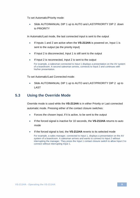
To set Automatic/Priority mode:
Slide AUTO/MANUAL DIP 1 up to AUTO and LAST/PRIORITY DIP 2 down
to PRIORITY
In Automatic/Last mode, the last connected input is sent to the output
If Inputs 1 and 2 are active when the VS-211HA is powered on, Input 1 is
sent to the output (as the priority input)
If Input 2 is disconnected, Input 1 is still sent to the output
If Input 2 is reconnected, Input 2 is sent to the output
For example, a salesman connected to Input 1 displays a presentation on the AV system of a boardroom. A second salesman arrives, connects to Input 2 and continues with his/her presentation.
To set Automatic/Last Connected mode:
Slide AUTO/MANUAL DIP 1 up to AUTO and LAST/PRIORITY DIP 2 up to
LAST
5.3 Using the Override Mode
Override mode is used while the VS-211HA is in either Priority or Last connected
automatic mode. Pressing either of the contact closure switches:
Forces the chosen input, if it is active, to be sent to the output
If the forced signal is inactive for 10 seconds, the VS-211HA returns to auto
mode
If the forced signal is lost, the VS-211HA reverts to its selected mode
For example, a sales manager, connected to Input 1, displays a presentation on the AV system of a boardroom. A salesman arrives and wants to connect to Input 2 without interrupting the manager. They press the Input 1 contact closure switch to allow Input 2 to connect without interrupting Input 1.

10 VS-211HA - Technical Specifications
6 Technical Specifications
INPUTS: 2 HDMI connectors, 2 unbalanced stereo audio on 3.5mm mini jacks
OUTPUTS: 1 HDMI connector, 1 unbalanced stereo audio on a 3.5mm mini jack
MAX. DATA RATE: 6.75Gbps (2.25Gbps per graphic channel)
COMPLIANCE WITH HDMI STANDARD:
Supports HDMI and HDCP
CONTROLS: Contact closure on a 3-pin terminal block, 2 priority DIP-switches
INDICATORS: ON and active input LEDs
POWER CONSUMPTION: 5V DC, 120mA (without load), 350mA (fully loaded)
OPERATING TEMPERATURE: 0° to +40°C (32° to 104°F)
STORAGE TEMPERATURE: -40° to +70°C (-40° to 158°F)
HUMIDITY: 10% to 90%, RHL non-condensing
DIMENSIONS: 12cm x 7.2cm x 2.4cm (4.7” x 2.8” x 0.9”) W. D. H
WEIGHT: 0.3kg (0.66lbs)
ACCESSORIES: Power supply
OPTIONS: RK-3T 19” rack adapter
Specifications are subject to change without notice at http://www.kramerelectronics.com

For the latest information on our products and a list of Kramer distributors, visit our Web site where updates to this user manual may be found.
We welcome your questions, comments, and feedback. Web site: www.kramerelectronics.com E-mail: [email protected]
P/N: 2900- 300378 Rev: 2
!SAFETY WARNINGDisconnect the unit from the powersupply before opening and servicing


![User Guide...User. {{]}]} {}]}](https://img.dokumen.tips/doc/110x75/60918ca14327954d24291644/-user-guide-user-.jpg)