Embed Size (px)
Citation preview

1
User manualfor the operator
Controls for THISION S PLUS / Combi
www.elco.net 9B.52.01.01 / 03.16
2
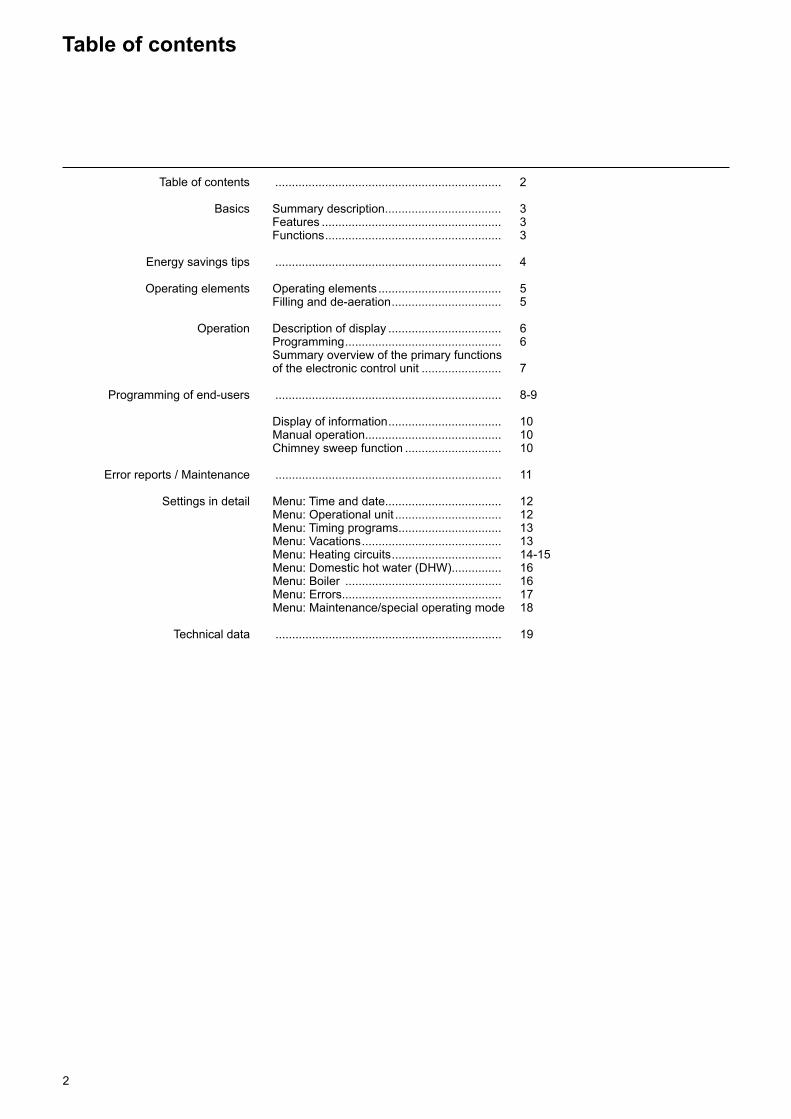
Table of contents
Table of contents .................................................................... 2
Basics Summary description ................................... 3 Features ...................................................... 3 Functions ..................................................... 3
Energy savings tips .................................................................... 4
Operating elements Operating elements ..................................... 5 Filling and de-aeration ................................. 5
Operation Description of display .................................. 6 Programming ............................................... 6 Summary overview of the primary functions of the electronic control unit ........................ 7
Programming of end-users .................................................................... 8-9
Display of information .................................. 10 Manual operation......................................... 10 Chimney sweep function ............................. 10
Error reports / Maintenance .................................................................... 11
Settings in detail Menu: Time and date................................... 12 Menu: Operational unit ................................ 12 Menu: Timing programs ............................... 13 Menu: Vacations .......................................... 13 Menu: Heating circuits ................................. 14-15 Menu: Domestic hot water (DHW) ............... 16 Menu: Boiler ............................................... 16 Menu: Errors ................................................ 17 Menu: Maintenance/special operating mode 18
Technical data .................................................................... 19
3
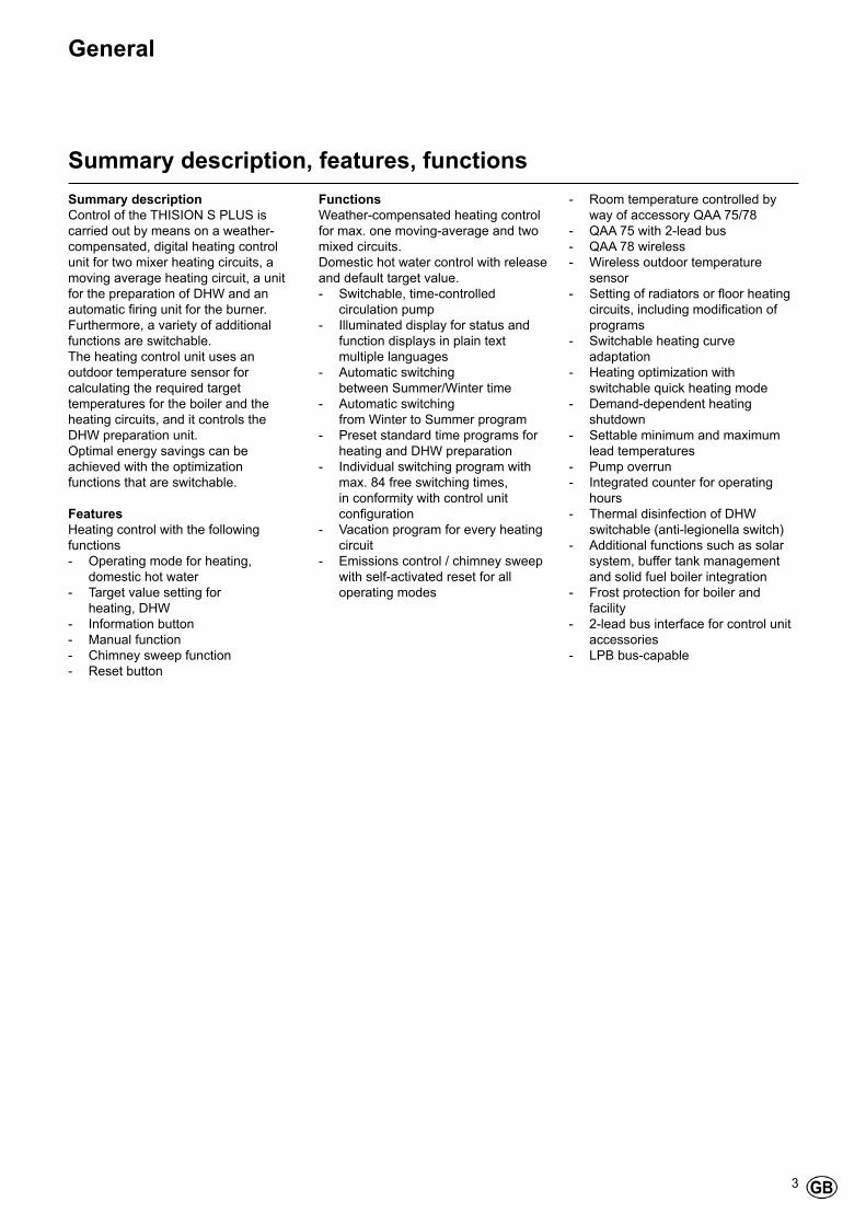
General
Summary description, features, functionsSummary descriptionControl of the THISION S PLUS is carried out by means on a weather-compensated, digital heating control unit for two mixer heating circuits, a moving average heating circuit, a unit for the preparation of DHW and an automatic firing unit for the burner. Furthermore, a variety of additional functions are switchable.The heating control unit uses an outdoor temperature sensor for calculating the required target temperatures for the boiler and the heating circuits, and it controls the DHW preparation unit.Optimal energy savings can be achieved with the optimization functions that are switchable.
FeaturesHeating control with the following functions- Operating mode for heating,
domestic hot water- Target value setting for heating, DHW- Information button- Manual function- Chimney sweep function- Reset button
FunctionsWeather-compensated heating control for max. one moving-average and two mixed circuits.Domestic hot water control with release and default target value.- Switchable, time-controlled
circulation pump- Illuminated display for status and
function displays in plain text multiple languages
- Automatic switching between Summer/Winter time- Automatic switching from Winter to Summer program- Preset standard time programs for
heating and DHW preparation- Individual switching program with
max. 84 free switching times, in conformity with control unit configuration
- Vacation program for every heating circuit
- Emissions control / chimney sweep with self-activated reset for all operating modes
- Room temperature controlled by way of accessory QAA 75/78
- QAA 75 with 2-lead bus- QAA 78 wireless- Wireless outdoor temperature
sensor- Setting of radiators or floor heating
circuits, including modification of programs
- Switchable heating curve adaptation
- Heating optimization with switchable quick heating mode
- Demand-dependent heating shutdown
- Settable minimum and maximum lead temperatures
- Pump overrun- Integrated counter for operating
hours- Thermal disinfection of DHW
switchable (anti-legionella switch)- Additional functions such as solar
system, buffer tank management and solid fuel boiler integration
- Frost protection for boiler and facility
- 2-lead bus interface for control unit accessories
- LPB bus-capable

4
Energy savings tips
Energy savings tips
Weather-compensated heating controlThe THISION S PLUS is delivered with a modern, energy-saving heating control. Depending on the outdoor temperature, namely weather-compensated, it generates the optimal lead temperature for heating the building. The characteristic heating curve must be adapted for this on your heating system, and to the heating requirements of your building. These settings will be carried out during the commissioning of your heating system, either by your heating engineer or by ELCO Customer Service.
Cost-effective heatingTo continually heat the rooms of a building to a comfort level is usually a waste. With the help of the thermostats on your radiators, you can set the temperature that is required for your comfort in each room.20 to 21°C will usually be enough for the living, working and children’s rooms. 15°C will usually be enough in unused rooms.
Reset modeBy means of timing programs that can be set in advance, it is possible to reduce the room temperature during night hours or in case of absence. Energy consultants recommend that the temperature is not reduced below 4°C. By closing the shutters during the night, it is also possible to save up to 15% energy.
Correct aeration of living roomsA short shock ventilation is more effective and saves more energy than leaving tilt windows open for longer periods. It is therefore recommended to carry out a five-minute shock ventilation several times per day. The advantage is: Due to the short aeration, the heat in the walls and the floors is not lost.
Domestic hot water temperaturePreset a suitable domestic hot water (DHW) temperature, which meets your requirements. Temperatures in excess of 55°C are usually not sensible and lead to an increased energy consumption. Furthermore, water temperatures in excess of 60°C lead to an increased lime precipitation. With the help of the timing programs available with THISION S PLUS, you can furthermore adapt warm water heating to times when you are absent.
DHW circulationA possibly available circulation pump for DHW should be operated on an as-needed basis. Circulating DHW, which is not used, is cooled on its way through the piping. That means that the DHW tanks must be heated additionally. With the help of an upstream timer switch, it is possible to optimize the DHW circulation to your needs.
Inspection and maintenanceA regular inspection of the heating equipment, both by your chimney sweep and the customer service of your dealer, ensures a long-term, energy-optimized and reliable operation of the facility. This is the reason why we also recommend that you conclude a maintenance contract, which includes an annual inspection and a need-oriented maintenance of your heating facility.

5
Operating elements
Operating elementsFilling and de-aerationLegend:A On/Off switchB Back button (ESC)C Room temperature control button D Confirmation button (OK)E Function button for manual
operation F Chimney sweep function button G Information button H Reset button I Operation mode button for heating
circuit(s) L DisplayM Operating mode button for DHW
Operating mode button for DHW (M)For switching on the DHW preparation (Bar under the water crane in the display)
Operation mode button for heating circuit(s) (I)For setting 4 different operating modes for heating Automatic clock: Automatic operation according to timer programSun 24 hr: Heating at comfort target valueMoon 24 hr: Heating at reduced valueProtection mode: Heating switched off - frost protection active
Display (L)
Information button (G)Retrieval of the following information, without influence on the control processes:Temperatures, operating condition of the heating facility/DHW, error reports
Room temperature control button (C)- For changing the room comfort
temperature - With this rotating button, settings
can be selected and changed during programming.
M A H
B C D E F
I
L
G
Confirmation button OK (D)Back button ESC (B)These two buttons are needed in combination with the large rotating button (- +) for the programming and configuration of the control unit. Settings, which cannot be changed through the control elements, are provided by means of programming.By pushing the ESC button you always go one step backward, whereby modified values are not taken over.
To reach the next operating level, or to store the changed values, you must push the OK button.
Manual operation function button (E)By pushing this button, the control unit is set to manual mode, whereby all pumps are running, the mixer is no longer controlled and the burner is set to 60°C. (Indicated by the spanner symbol)
Chimney sweep function button (F)Push this button shortly, to put the boiler in the operating mode for measuring emissions; renewed pushing of the button deactivates this function, or it is automatically deactivated after 15 minutes (indicated by the spanner symbol).May only be operated by the chimney sweep!
Reset button (H)By pressing this button shortly, the locked condition of the burner is deactivated.
On/Off switch (A)Position 0:The entire facility and all connected electrical components are without electrical power. A protection against frost is not ensured.
Position I:The entire facility and all connected electrical components are ready for operation.
Filling and de-aeration of the THISION S PLUS and the heating facilityThe heating facility is filled according to the standard method.The facility must have been deaerated, both on the heating and the warm water side.The water pressure can be read off in bar, either on the analog pressure indicator or via the information button. The boiler is ready for operation, as soon as the heating facility has been filled and deaerated.After an appropriate period, the water pressure should be checked and, if necessary, water should be topped up. (Note: Before topping up the water, first fill the hose with water, which prevents the entry of air into the heating system).
Use the pump de-aeration function to remove all air from the pump and the boiler: Hold down the E button for more than 3 seconds. This function runs for approximately 16 minutes.
During the initial commissioning, or after filling or topping up the heating facility, always first activate the de-aeration function.
6
Operation
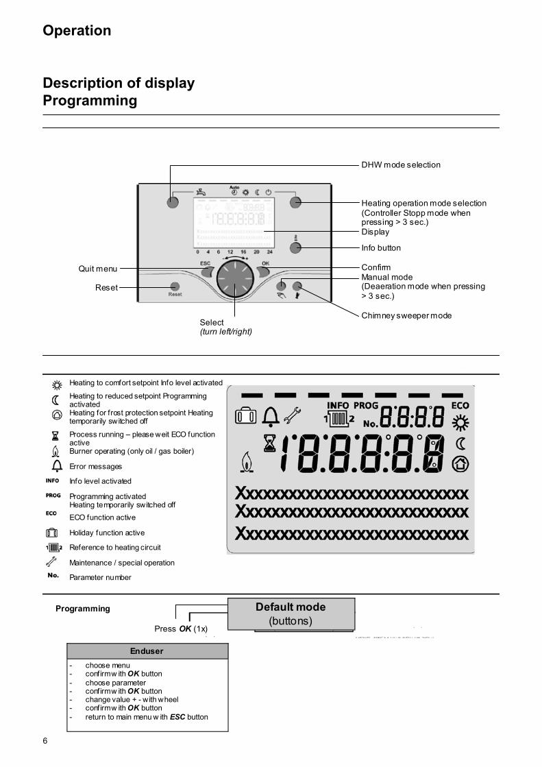
Description of displayProgramming
- gew ünschtes Menü auswählen - mit Taste OK bestätigen - mit Taste ESC zurück zur Grundanzeige
- gew ünschte Benutzer-Ebene auswählen - mit Taste OK bestätigen - gew ünschtes Menü auswählen - mit Taste OK bestätigen - mit Taste ESC zurück zur Grundanzeige
DHW mode selection Heating operation mode selection (Controller Stopp mode when pressing > 3 sec.) Display Info button Confirm Manual mode (Deaeration mode when pressing > 3 sec.) Chimney sweeper mode
Enduser
- choose menu - confirm w ith OK button - choose parameter - confirm w ith OK button - change value + - with wheel - confirm w ith OK button - return to main menu w ith ESC button
Programming
Select (turn left/right)
Quit menu
Reset
Press OK (1x)
Default mode (buttons)
Heating to comfort setpoint Info level activated
Heating to reduced setpoint Programming activated Heating for frost protection setpoint Heating temporarily switched off
Process running – please weit ECO function active Burner operating (only oil / gas boiler) Error messages Info level activated Programming activated Heating temporarily switched off
ECO function active Holiday function active Reference to heating circuit Maintenance / special operation Parameter number
7
Operation
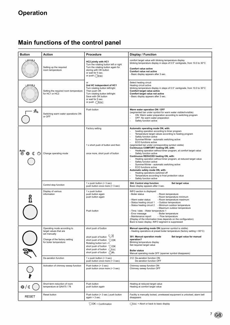
Main functions of the control panelButton Action Procedure Display / Function
Setting up the required room temperature
HC2 jointly with HC1 Turn the rotating button left or right Turn the rotating button again for storing with OK buttonor wait for 5 sec.or push
comfort target value with blinking temperature displayblinking temperature display in steps of 0.5° centigrade, from 10.0 to 30°C
Comfort value active Comfort value not active- Basic display appears after 3 sec.
Setting the required room temperature for HC1 or HC2
or 2nd HC independent of HC1Turn rotating button left/right Then push OKTurn rotating button left/right Save with OK button or wait for 5 sec. or push
Select heating circuitHeating circuit activeblinking temperature display in steps of 0.5° centigrade, from 10.0 to 30°CComfort target value active Comfort target value not active- Basic display appears after 3 sec.
Switching warm water operations ON or OFF
Push button Warm water operation ON / OFF(segmented bar under symbol for warm water visible/invisible)- ON: Warm water preparation according to switching program- OFF: No warm water preparation- Safety function active
Change operating mode
Factory setting
1 x short push of button and then
once more, short push of button
Automatic operating mode ON, with:- heating operation according to timer program- Temperature target values according to heating program- Safety function active- Summer/Winter - automatic switching active- ECO functions active(segmented bar under corresponding symbol visible)Continuous COMFORT heating ON, with:- Heating operation without timer program, at comfort target value- Safety function activeContinuous REDUCED heating ON, with:- Heating operation without timer program, at reduced target value- Safety function active- Summer/Winter - automatic switching active- ECO functions activeAutomatic safety mode ON, with:- Heating operations switched off- Temperature according to frost protection value- Safety function active
Control stop function1 x push button (> 3 sec) push button once more (> 3 sec)
304: Control stop function Set target valueBasic display appears after 3 sec.
Display of various information
1 x push buttonpush button againpush button again
Push button
INFO section is displayed- Boiler status - Room temperature - Room temperature minimum- Warm water status - Room temperature maximum- Status heating circuit 1 - Outdoor temperature- Status heating circuit 2 - Minimum outdoor temperature - Maximum outdoor temperature- Time / date - Water temperature 1- Error message - Boiler temperature- Maintenance report - Flow temperature(Display of the information lines depends on the configuration) Back to basic display; INFO segment is suppressed
Operating mode according to target values that are set manually
Change of the factory setting for boiler temperature
short push of button
short push of button short push of button Rotating button turn -/+short push of button short push of button short push of button
Manual operating mode ON (spanner symbol is visible)- Heating operations at preset boiler temperature (factory setting = 60°C)
301: Manual operation mode Set target value for manual operation?Blinking temperature display Set required target value
Boiler statusManual operating mode OFF (spanner symbol disappears)
De-aeration function 1 x push button (> 3 sec) push button once more (> 3 sec)
312: De-aeration function ON De-aeration function OFF
Activation of chimney sweep function Push button (> 3 sec) push button once more (> 3 sec)
Chimney sweep function ON Chimney sweep function OFF
Short-term reduction of room temperature at QAA75 / 78
Push button push button again
Heating at reduced target value Heating at comfort target value
RESETReset button Push button (< 3 sec.) push button
again > 3 sec.Facility is manually locked, unreleased equipment is unlocked, alarm bell disappears
= Confirmation = Abort or back to basic display
8
Parameters end users
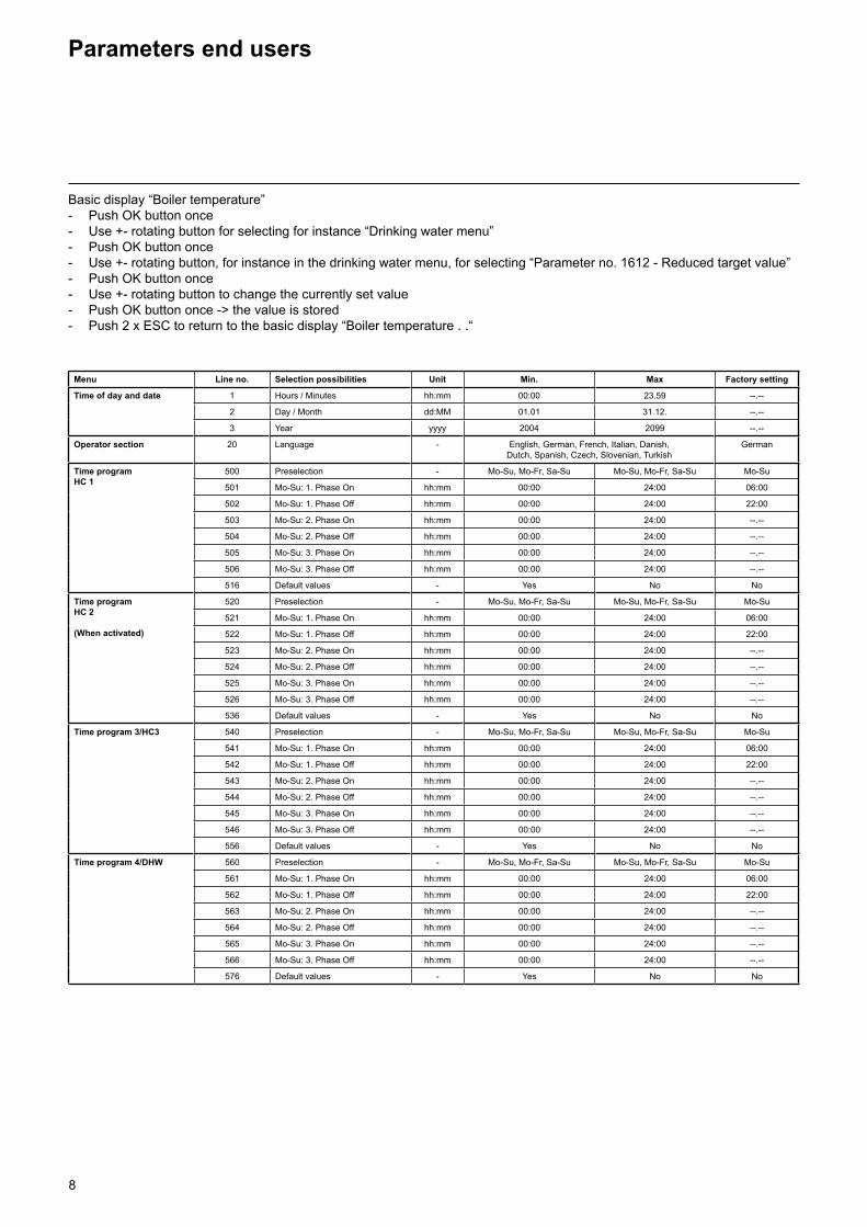
Basic display “Boiler temperature”- Push OK button once- Use +- rotating button for selecting for instance “Drinking water menu”- Push OK button once- Use +- rotating button, for instance in the drinking water menu, for selecting “Parameter no. 1612 - Reduced target value”- Push OK button once- Use +- rotating button to change the currently set value- Push OK button once -> the value is stored - Push 2 x ESC to return to the basic display “Boiler temperature . .“
Menu Line no. Selection possibilities Unit Min. Max Factory setting
Time of day and date 1 Hours / Minutes hh:mm 00:00 23.59 --.--
2 Day / Month dd:MM 01.01 31.12. --.--
3 Year yyyy 2004 2099 --.--
Operator section 20 Language - English, German, French, Italian, Danish,Dutch, Spanish, Czech, Slovenian, Turkish
German
Time programHC 1
500 Preselection - Mo-Su, Mo-Fr, Sa-Su Mo-Su, Mo-Fr, Sa-Su Mo-Su
501 Mo-Su: 1. Phase On hh:mm 00:00 24:00 06:00
502 Mo-Su: 1. Phase Off hh:mm 00:00 24:00 22:00
503 Mo-Su: 2. Phase On hh:mm 00:00 24:00 --.--
504 Mo-Su: 2. Phase Off hh:mm 00:00 24:00 --.--
505 Mo-Su: 3. Phase On hh:mm 00:00 24:00 --.--
506 Mo-Su: 3. Phase Off hh:mm 00:00 24:00 --.--
516 Default values - Yes No No
Time programHC 2
(When activated)
520 Preselection - Mo-Su, Mo-Fr, Sa-Su Mo-Su, Mo-Fr, Sa-Su Mo-Su
521 Mo-Su: 1. Phase On hh:mm 00:00 24:00 06:00
522 Mo-Su: 1. Phase Off hh:mm 00:00 24:00 22:00
523 Mo-Su: 2. Phase On hh:mm 00:00 24:00 --.--
524 Mo-Su: 2. Phase Off hh:mm 00:00 24:00 --.--
525 Mo-Su: 3. Phase On hh:mm 00:00 24:00 --.--
526 Mo-Su: 3. Phase Off hh:mm 00:00 24:00 --.--
536 Default values - Yes No No
Time program 3/HC3
540 Preselection - Mo-Su, Mo-Fr, Sa-Su Mo-Su, Mo-Fr, Sa-Su Mo-Su
541 Mo-Su: 1. Phase On hh:mm 00:00 24:00 06:00
542 Mo-Su: 1. Phase Off hh:mm 00:00 24:00 22:00
543 Mo-Su: 2. Phase On hh:mm 00:00 24:00 --.--
544 Mo-Su: 2. Phase Off hh:mm 00:00 24:00 --.--
545 Mo-Su: 3. Phase On hh:mm 00:00 24:00 --.--
546 Mo-Su: 3. Phase Off hh:mm 00:00 24:00 --.--
556 Default values - Yes No No
Time program 4/DHW 560 Preselection - Mo-Su, Mo-Fr, Sa-Su Mo-Su, Mo-Fr, Sa-Su Mo-Su
561 Mo-Su: 1. Phase On hh:mm 00:00 24:00 06:00
562 Mo-Su: 1. Phase Off hh:mm 00:00 24:00 22:00
563 Mo-Su: 2. Phase On hh:mm 00:00 24:00 --.--
564 Mo-Su: 2. Phase Off hh:mm 00:00 24:00 --.--
565 Mo-Su: 3. Phase On hh:mm 00:00 24:00 --.--
566 Mo-Su: 3. Phase Off hh:mm 00:00 24:00 --.--
576 Default values - Yes No No
9
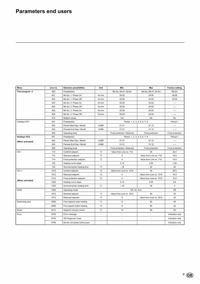
Parameters end users
Menu Line no. Selection possibilities Unit Min. Max Factory setting
Time program 5 600 Preselection - Mo-Su, Mo-Fr, Sa-Su Mo-Su, Mo-Fr, Sa-Su Mo-Su
601 Mo-Su: 1. Phase On hh:mm 00:00 24:00 06:00
602 Mo-Su: 1. Phase Off hh:mm 00:00 24:00 22:00
603 Mo-Su: 2. Phase On hh:mm 00:00 24:00 --.--
604 Mo-Su: 2. Phase Off hh:mm 00:00 24:00 --.--
605 Mo-Su: 3. Phase On hh:mm 00:00 24:00 --.--
606 Mo-Su: 3. Phase Off hh:mm 00:00 24:00 --.--
616 Default values - Yes No No
Holidays HC1 641 Preselection - Period 1, 2, 3, 4, 5, 6, 7, 8 Period 1
642 Period Start Day / Month tt.MM 01.01 31.12 --.--
643 Periode End Day / Month tt.MM 01.01 31.12 --.--
648 Operating level - Frost protection, Reduced Frost protection Frost protection
Holidays HC2
(When activated)
651 Preselection - Period 1, 2, 3, 4, 5, 6, 7, 8 Period 1
652 Period Start Day / Month tt.MM 01.01 31.12 --.--
653 Periode End Day / Month tt.MM 01.01 31.12 --.--
658 Operating level - Frost protection, Reduced Frost protection Frost protection
HC1 710 Comfort setpoint °C Value from Line no. 712 35 20.0
712 Reduced setpoint °C 4 Value from Line no. 710 16.0
714 Frost protection setpoint °C 4 Value from Line no. 712 10.0
720 Heating curve slope - 0.10 4.00 1.50
730 Summer/winter heating limit °C ---/8 30 20
HC 2
(When activated)
1010 Comfort setpoint °C Value from Line no. 1012 35 20.0
1012 Reduced setpoint °C 4 Value from Line no. 1010 16.0
1014 Frost protection setpoint °C 4 Value from Line no. 1012 10.0
1020 Heating curve slope - 0.10 4.00 0.8
1030 Summer/winter heating limit °C ---/8 30 0
DHW 1600 Operating mode - Off, On, Eco Off
1610 Nominal setpoint °C Value from Line no. 1612 80 55
1612 Reduced setpoint °C 8 Value from Line no. 1610 40
Swimming pool 2055 Pool setpoint solar heating °C 8 80 26
2056 Pool sepoint boiler heating °C 8 80 22
Boiler 2214 Setpoint manual control °C 10 90 50
Error 6700 Error message - - - Indication only
6705 SW Diagnose Code - - - Indication only
6706 Burner ctrl phase lockout pos - - - Indication only
10
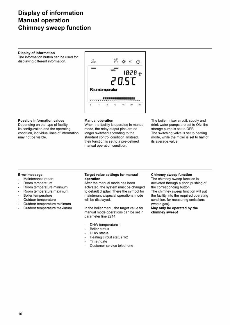
Display of informationManual operationChimney sweep function
0 4 8 12 16 20 24
AUTO
Raumtemperatur
Display of informationThe information button can be used for displaying different information.
The boiler, mixer circuit, supply and drink water pumps are set to ON; the storage pump is set to OFF.The switching valve is set to heating mode, while the mixer is set to half of its average value.
Target value settings for manual operationAfter the manual mode has been activated, the system must be changed to default display. There the symbol for maintenance/special operations mode will be displayed.
In the boiler menu, the target value for manual mode operations can be set in parameter line 2214.
- DHW temperature 1- Boiler status- DHW status- Heating circuit status 1/2- Time / date- Customer service telephone
Possible information valuesDepending on the type of facility, its configuration and the operating condition, individual lines of information may not be visible.
Manual operationWhen the facility is operated in manual mode, the relay output pins are no longer switched according to the standard control condition. Instead, their function is set to a pre-defined manual operation condition.
Error message- Maintenance report- Room temperature- Room temperature minimum- Room temperature maximum- Boiler temperature- Outdoor temperature- Outdoor temperature minimum- Outdoor temperature maximum
Chimney sweep functionThe chimney sweep function is activated through a short pushing of the corresponding button. The chimney sweep function will put the facility into the required operating condition, for measuring emissions (waste gas).May only be operated by the chimney sweep!
11
Error reports / Maintenance
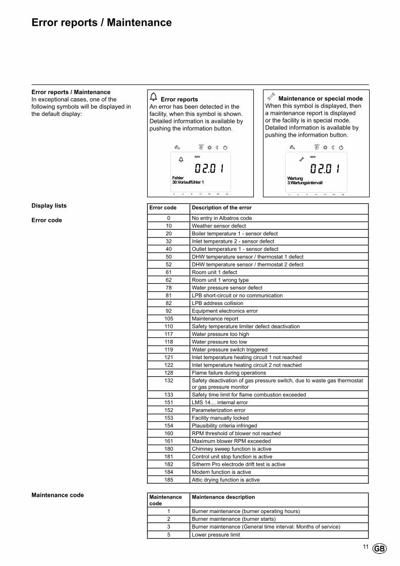
Error reportsAn error has been detected in the facility, when this symbol is shown. Detailed information is available by pushing the information button.
Error reports / MaintenanceIn exceptional cases, one of the following symbols will be displayed in the default display:
Maintenance or special modeWhen this symbol is displayed, then a maintenance report is displayed or the facility is in special mode. Detailed information is available by pushing the information button.
Text3 Text430:Vorlauffühler 1
0 4 8 12 16 20 24
AUTO
Fehler
Text3 Text43:Wartungsintervall
0 4 8 12 16 20 24
AUTO
Wartung
Display lists
Error code
Maintenance code
Error code Description of the error
0 No entry in Albatros code10 Weather sensor defect20 Boiler temperature 1 - sensor defect32 Inlet temperature 2 - sensor defect40 Outlet temperature 1 - sensor defect50 DHW temperature sensor / thermostat 1 defect52 DHW temperature sensor / thermostat 2 defect61 Room unit 1 defect62 Room unit 1 wrong type78 Water pressure sensor defect81 LPB short-circuit or no communication82 LPB address collision92 Equipment electronics error
105 Maintenance report110 Safety temperature limiter defect deactivation117 Water pressure too high118 Water pressure too low119 Water pressure switch triggered121 Inlet temperature heating circuit 1 not reached122 Inlet temperature heating circuit 2 not reached128 Flame failure during operations132 Safety deactivation of gas pressure switch, due to waste gas thermostat
or gas pressure monitor133 Safety time limit for flame combustion exceeded151 LMS 14… internal error152 Parameterization error153 Facility manually locked154 Plausibility criteria infringed160 RPM threshold of blower not reached161 Maximum blower RPM exceeded180 Chimney sweep function is active181 Control unit stop function is active182 Sitherm Pro electrode drift test is active184 Modem function is active185 Attic drying function is active
Maintenance code
Maintenance description
1 Burner maintenance (burner operating hours)2 Burner maintenance (burner starts)3 Burner maintenance (General time interval: Months of service)5 Lower pressure limit
12
Settings in detail
Menu: Time and dateMenu: Operational unit
Units
The display can be switched between SI units (°C, bar) and US units (°F, PSI).
Time and dateThe control unit is fitted with a 365-day clock, which provides the time, the day of the week and the date. To ensure a correct functionality, the time and the date must be correctly set
Handling and display
LanguageYou can select the following languages for the display: German, English, Italian, French or Dutch.
Line no. Operating line Factory setting
1 Hours / Minutes2 Day / Month3 Year
Line no. Operating line Factory setting
20 Language German
Line no. Operating line Factory setting
29 Units °C / bar
13
Menu: Timing programsMenu: VacationsDifferent switching programs are available for the heating circuits and the preparation of DHW.These are set to the operating mode “Automatic”, and they control the change of the temperature level (and the corresponding target values) for the different switching times that have been set.
Entry of switching timesThe switching times can be set in combination, namely for several days jointly, or for separate times on single days. Through a pre-selection of a groups, such as for instance Mon...Fr. and Sat...Sun, which have the same switching times, the setting of switching programs is shortened substantially.
Line no. Operating line Factory setting
HC1 HC2 3/HCP 4/DHW500 520 540 560 Preselection
Mon - Sun Mon - Fri Sat - Sun Mon . . . Sun
Mon - Sun
501 521 541 561 1. Phase ON 6 : 00502 522 542 562 1. Phase OFF 22 : 00503 523 543 563 2. Phase ON - - : - -504 524 544 564 2. Phase OFF - - : - -505 525 545 565 3. Phase OFF - - : - -506 526 546 566 3. Phase OFF - - : - -
Copy day to
Standard program
Vacations
By using the vacations program, heating circuits can be switched to a selectable operating level by calendar date. Heating, however, does not resume on the ending day.Only on the next day is heating switched to the comfort target value and according to the timer program.
Line no. Operating line
515, 535, 555, 575 Copy day to
Line no. Operating line
516, 536, 556, 576 Standard values
When only one weekday is selected as a preselected day, then the time phases can be copied to other weekdays.
All timer switching programs can be reset to the factory settings. Each timer switching program has its own operating line for such a reset.
NoteIndividual settings are lost during a reset!
Line no. Operating line Factory setting
VG1 VG2642 652 Start - - : - -643 653 End - - : - -648 658 Operating level
Frost protectionReduced
Frost protection
- The vacation program can only be used in automatic operating mode.

14
Menu: Heating circuits
Room target values
Room temperatureThe room temperature can be set according to different target values. These target values come into effect with the selected operating mode, thereby resulting in different temperature levels in each of the rooms. The range of target values that can be set is limited by their mutual dependence, which can be seen in the accompanying graphic illustration.
Frost protectionDuring protected mode operations, a too strong lowering of the room temperature is automatically prevented. The heating unit will be automatically set to the room temperature target value for frost protection.
A variety of functions is available and can be individually set for each heating circuit.
Characteristic heating curveThe inlet temperature target value is set by means out of the characteristic heating curve, for which an inlet temperature is set that depends on the actual weather conditions. This characteristic heating curve can be modified by means of various settings, so that the heating performance and the room temperature conform to the personal requirements.
Line no. Operating line Factory setting
VG1 VG2710 1010 Comfort target value 20°C712 1012 Reduced target value 16°C714 1014 Frost protection target value 10°C
TRKmax Maximum comfort target valueTRK Comfort target valueTRR Reduced target valueTRF Frost protection target value
Line no. Operating line Factory setting
VG1 VG2720 Characteristic curve steepness HC1 1,5
1020 Characteristic curve steepness HC2 0,8
15
Menu: Heating circuits Characteristic curve steepnessThe inlet temperature increases as the characteristic curve becomes steeper, namely the colder the outdoor temperature is. This means that when the room temperature changes, in case of a cold outdoor temperature, and does not in case of a warm outdoor temperature, then the steepness must be corrected.
Raise the setting: Increases the inlet temperature, especially during cold outdoor temperatures.
Lower the setting: Decreases the inlet temperature, primarily during cold outdoor temperatures.
16
Menu: Domestic hot water Target valuesDomestic hot water can be regulated according to different target values. These target values come into effect with the selected operating mode, thereby resulting in different temperature levels in the DWH tank.
TWWR DHW reduced target valueTWWN DHW nominal target valueTWWmax Maximum DHW nominal target value
Menu: Boiler
Line no. Operating line Factory setting
1610 Nominal target value 55°C1612 Reduced target value 40°C
Line no. Operating line Factory setting
2214 Target value for manual operation 60 °C
Target value for manual operation Boiler temperature target value, which is set during activated manual operations.
17
Menu: ErrorsErrors
When an error is detected, then an error report can be called up via the Information button in the information level. The display will describe the cause of the error.
Maintenance functions
Maintenance reports are automatically generated reports, which indicate the required maintenance works.This function must be activated by your heating technician.
ReportA maintenance code is shown here.
Acknowledgment of reportBy acknowledging the report with “Yes” this report will no longer be displayed.
Line no. Operating line Factory setting
6705 Current diagnosis code - - -
ReportA maintenance code is shown here.
Line no. Operating line Factory setting
7001 Report Only display7010 Acknowledgment of report NO
18
Manual operationWhen the facility is operated in manual mode, the relay output pins are no longer switched according to the standard control condition. Instead, their function is set to a pre-defined manual operation condition.
Target value settings for manual operationAfter the manual mode has been activated, the system must be changed over to default display. There the symbol for maintenance/special operations mode will be displayed .By pushing on the information button, the display changes to “Manual operation”, in which the target value can be set.
Line no. Operating line Factory setting
7140 Manual operation OFF
Menu: Maintenance/special operating mode
19
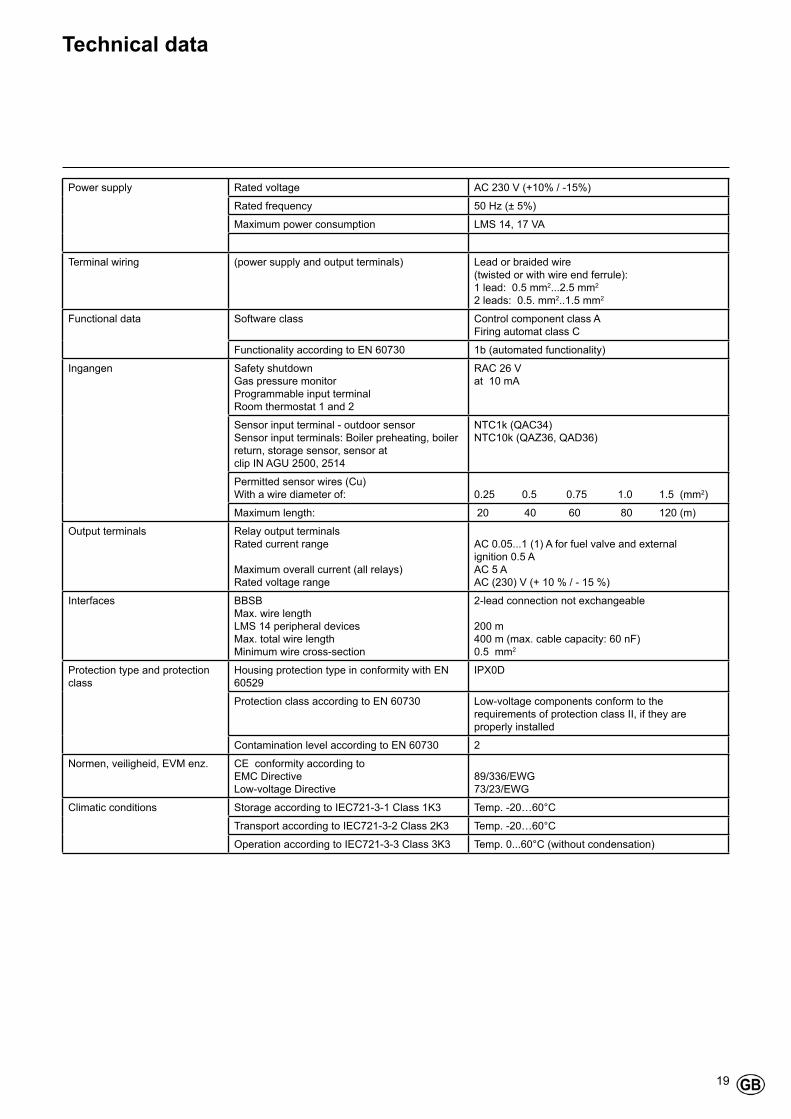
Technical data
Power supply Rated voltage AC 230 V (+10% / -15%)
Rated frequency 50 Hz (± 5%)
Maximum power consumption LMS 14, 17 VA
Terminal wiring (power supply and output terminals) Lead or braided wire(twisted or with wire end ferrule): 1 lead: 0.5 mm2...2.5 mm2
2 leads: 0.5. mm2..1.5 mm2
Functional data Software class Control component class A Firing automat class C
Functionality according to EN 60730 1b (automated functionality)
Ingangen Safety shutdownGas pressure monitorProgrammable input terminalRoom thermostat 1 and 2
RAC 26 Vat 10 mA
Sensor input terminal - outdoor sensorSensor input terminals: Boiler preheating, boiler return, storage sensor, sensor at clip IN AGU 2500, 2514
NTC1k (QAC34)NTC10k (QAZ36, QAD36)
Permitted sensor wires (Cu)With a wire diameter of: 0.25 0.5 0.75 1.0 1.5 (mm2)
Maximum length: 20 40 60 80 120 (m)
Output terminals Relay output terminalsRated current range
Maximum overall current (all relays)Rated voltage range
AC 0.05...1 (1) A for fuel valve and external ignition 0.5 AAC 5 AAC (230) V (+ 10 % / - 15 %)
Interfaces BBSBMax. wire length LMS 14 peripheral devicesMax. total wire lengthMinimum wire cross-section
2-lead connection not exchangeable 200 m400 m (max. cable capacity: 60 nF)0.5 mm2
Protection type and protection class
Housing protection type in conformity with EN 60529
IPX0D
Protection class according to EN 60730 Low-voltage components conform to the requirements of protection class II, if they are properly installed
Contamination level according to EN 60730 2
Normen, veiligheid, EVM enz. CE conformity according to EMC DirectiveLow-voltage Directive
89/336/EWG 73/23/EWG
Climatic conditions Storage according to IEC721-3-1 Class 1K3 Temp. -20…60°C
Transport according to IEC721-3-2 Class 2K3 Temp. -20…60°C
Operation according to IEC721-3-3 Class 3K3 Temp. 0...60°C (without condensation)

20
Service:
www.elco.net
ELCO GmbH D - 72379 Hechingen ELCO Austria GmbH A - 2544 Leobersdorf ELCOTHERM AG CH - 7324 Vilters ELCO BV NL - 6465 AG Kerkrade ELCO Belgium SA B - 1070 Brussel ELCO Italia S.p.A. I - 31023 Resana ELCO United Kingdom UK - Basildon, Essex, SS15 6SJ ELCO France / Chaffoteaux SAS F - 93521 Saint-Denis Cedex Gastech-Energi A/S DK - 8240 Risskov