Embed Size (px)
Citation preview
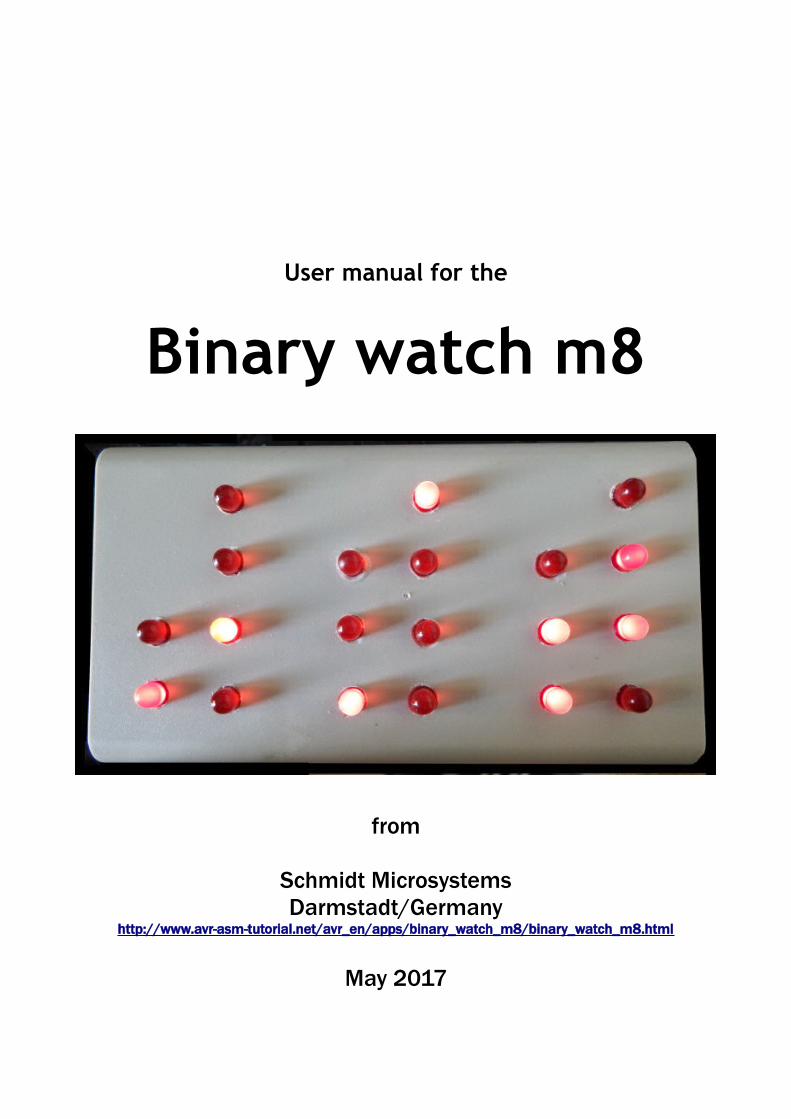
User manual for the
Binary watch m8
from
Schmidt MicrosystemsDarmstadt/Germany
http://www.avr-asm-tutorial.net/avr_en/apps/binary_watch_m8/binary_watch_m8.html
May 2017

Congratulations for buying the binary watch m8!
You now have a super-modern microcontroller watch with an xtal controlled tick of exactly 2.465.700 Hertz and a division down to exactly one second.
This is not a digital watch where you see ugly formed numbers on a seven-segment display with 48 straight-formed light-emitting diodes. Instead it has only twenty light-emitting-diodes of a round shape. As an example you see the display of 24 hours in the night: all lamps are off, because it is 00:00:00.
Time display is a matter of mental arithmetic here. You have to add 0 and 0 to get the tens of the hour, 0 and 0 and 0 and 0 for the ones of the hours. And so on for the minutes and the seconds.In another example we have to add the following.
Add 2 and 0 for the tens of the hour, add 1 and 2 for the ones of the hour, add 20 and 3 for the whole hours. Proceed in that way to calculate the minutes and the seconds. Binary is always 1 – 2 – 4 – 8, add those all up if the diodes are on. That is why it is called a binary coded digit watch.
No opportunity exists to adjust the watch to current time. You will have to switch off the watch on 11:59:00 by pulling the plug. Exactly at 12:00:00 push in the

plug again and the watch now is exact for roughly one month. After that, or if a power-off occurs in between, re-adjust the watch again with repeating that procedure. You can use another alarm clock or your smart phone to remind yourself regularly.
The watch has no alarm function, so you can sleep as long as you want.
Power source:
Depending from your watch designer's decision, the power comes either from a 230 or 110 V wall plug. Consumption over one year is at maximum 10 kilowatthours and costs approximately three Euros or Dollars.
Maintenance:
The device is majorly free of maintenance. Remove dust from the LEDs with a dry cleaning cloth once every year.
Repair:
You can open the box for repairs. But make sure that you remove the wall plug first to avoid electric shocks. The device has a fuse (Sicherung) below the plastic cover as shown here. If this fuse is blown, replace it with a 100mA delay fuse. No other repair activities make sense. It is normal if the heat sink and the transformer are warm after use, so do not care about this.
Quality:
The power supply unit has been tested with an overcurrent of 300mA for
several hours and has not failed.The software was tested in a High-Speed-Mode (1 minute in 1 second, 1 hour in 1 second) and all was fine.No ISO9000, no Euro safety seal, no technical inspection. But all high quality.
Warranty:
Designer guarantees two years of correct function. If defective you will have to call our service number 0900-1234567 (costs 99 Euro per minute). The following repair is cost-free, but only if you did not throw the watch into a bathtub or from an airplane.
Attachments:1. Schematic of the controller device2. Schematic of lamps and plugs3. Schematic of the power supply unit4. Layout of device5. Program of the microprofessor in AVR assembler language
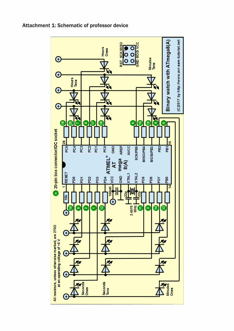
Attachment 1: Schematic of professor device

Attachment 2: Schematic of lamps and plugs

Attachment 3: Schematic of the power supply

Attachment 4: Layout of professor device

Attachment 5: Program of microprofessor in AVR assembler language;; **********************************************; * Binary watch with 20 LEDs and ATmega8A *; * Version 1, April 2017 *; * (C)2017 by http://www.avr-asm-tutorial.net *; **********************************************;.NOLIST.INCLUDE "m8Adef.inc" ; Header file for ATMEGA8A.LIST;; =====================================; A S S E M B L E R - S W I T C H E S; =====================================;; These two switches should be 0 for normal operation.equ speed = 0 ; 0 = normal, 1 = Test minutes, 2 = Test hours.equ fast = 0 ; Fast through for debugging (1: Prescaler=1);; This switch is a matter of taste, pbcd=1 is faster.equ pbcd = 1 ; 1 = Time in Packed BCD, 0 = Binary;; ============================================; H A R D W A R E I N F O R M A T I O N; ============================================;; ATmega8A; ________________; ISP6+ 1 / |28; RESET o--|reset PC5|--o HourT2; 2| |27; SecO1 o--|PD0 PC4|--o HourT1; 3| |26; SecO2 o--|PD1 PC3|--o HourO8; 4| |25; SecO4 o--|PD2 PC2|--o HourO4; 5| |24; SecO8 o--|PD3 PC1|--o HourO2; 6| |23; SecT1 o--|PD4 PC0|--o HourO1; 7| |22; +5 V o--|vcc gnd|--o NC; 8| |21; 0 V o--|gnd AREF|--o NC; 9| |20; Xtal o--|XTAL1 AVCC|--o NC; 2.4576 10| |19; MHz o--|XTAL2 PB5/SCK|--o MinT4+ISP6-SCK; 11| |18; SecT2 o--|PD5 PB4/MISO|--o MinT2+ISP6-MISO; 12| |17; SecT4 o--|PD6 PB3/MOSI|--o MinT1+ISP6-MOSI; 13| |16; MinO1 o--|PD7 PB2|--o MinO8; 14| |15; MinO2 o--|PB0 PB1|--o MinO4; |_________________|; ;; ================================================; C O N S T A N T S T O B E A D J U S T E D; ================================================

;.equ clock = 2457600 ; Clock frequency, external Xtal;; =======================================================; F I X E D A N D D E R I V E D C O N S T A N T S; =======================================================;.if speed == 0 ; normal speed .equ cPresc = 1024 ; Prescaler Timer 1 .equ cCtc = clock/cPresc - 1 ; CTC value Timer 1 .endif.if speed == 1 ; Minute test .equ cPresc = 64 .equ cCtc = clock/cPresc/60 - 1 .endif.if speed == 2 ; Hour test .equ cPresc = 1 .equ cCtc = (clock/cPresc+1800)/3600 - 1 .endif;; ============================================; R E G I S T E R D E F I N I T I O N S; ============================================;; free: R0 to R15.def rmp1 = R16 ; Multi purpose register 1.def rmp2 = R17 ; Multi purpose register 2.def rSec = R18 ; Seconds.def rMin = R19 ; Minutes.def rHour = R20 ; Hours.def rPD = R21 ; Port output register Port D .def rPB = R22 ; dto., Port B.def rPC = R23 ; dto., Port C; free: R24 to R31;; ============================================; S R A M D E F I N I T I O N S; ============================================;.DSEG.ORG 0X0060; (SRAM only used for interrupt and as Call-Stack);; ==============================================; R E S E T A N D I N T V E C T O R S; ==============================================;.CSEG.ORG $0000
rjmp Main ; Reset-Vectorreti ; INT0reti ; INT1reti ; TC2COMPreti ; TC2OVFreti ; TC1CAPTrjmp SecInt ; TC1COMPA, Second interruptreti ; TC1COMPBreti ; TC1OVFreti ; TC0OVFreti ; SPI_STCreti ; UART-RXreti ; UART-UDREreti ; UART-TXCreti ; ADC

reti ; EERDYreti ; ANACOMPreti ; TWIreti ; SPMRDY
;; ==========================================; I N T E R R U P T S E R V I C E; ==========================================;; Second interrupt; No other interrupts occur and there are no; instructions to be executed outside this; interrupt service routine.SecInt: ; Second Interrupt
inc rSec ; next second.if pbcd == 1; Packed-BCD
ldi rmp1,0x06 ; for Packed-BCD half overflowadd rSec,rmp1 ; Half overflow?brhs SecInt1 ; Yes, test seconds=60sub rSec,rmp1 ; No half overflow, subtractrjmp SecInt4 ; Ready to output
SecInt1:cpi rSec,0x60 ; 60 seconds?brcs SecInt4 ; No, go to outputclr rSec ; Yes, seconds = 0inc rMin ; Next minuteadd rMin,rmp1 ; Half overflow?brhs SecInt2 ; Yes, test 60 minutessub rMin,rmp1 ; No, subtractrjmp SecInt4 ; To output
SecInt2:cpi rMin,0x60 ; 60 minutes?brcs SecInt4 ; No, to outputclr rMin ; Minutes = 0inc rHour ; Next houradd rHour,rmp1 ; Half overflow?brhs SecInt3 ; Yes, test 24 hourssub rHour,rmp1 ; No, subtractrjmp SecInt4 ; To output
SecInt3:cpi rHour,0x24 ; 24 hours?brcs SecInt4 ; No, to outputclr rHour ; Clear hours
SecInt4: ; Prepare outputmov rPC,rHour ; Port C are the hoursmov rPD,rSec ; Port D are the secondslsl rPD ; Shift D leftmov rPB,rMin ; Port B are the minuteslsr rPB ; Shift lowest bit to carryror rPD ; And roll C into the highest bit of Dcom rPD ; Invert portbits in D (LED polarity)com rPB ; Invert portbits in Bandi rPB,0x3F ; Clear bits 7 and 6 in Bcom rPC ; Invert portbits in Candi rPC,0x3F ; Clear bits 7 and 6 in C; Output to portsout PORTD,rPDout PORTB,rPBout PORTC,rPCreti ; ready.else; Binary clock in three registerscpi rSec,60 ; 60 seconds?

brcs SecInt1 ; No, to outputclr rSec ; Yes, clear secondsinc rMin ; Next minutecpi rMin,60 ; 60 minutes?brcs SecInt1 ; No, to outputclr rMin ; Yes, clear minutesinc rHour ; Next hourcpi rHour,24 ; 24 hours?brcs SecInt1 ; No, to outputclr rHour ; Yes, clear hours
SecInt1: ; Prepare outputmov rmp1,rSec ; Seconds to registerrcall Div10 ; Divide by 10mov rPD,rmp1 ; Remainder to port register Dswap rmp2 ; Tens to upper nibbleor rPD,rmp2 ; Combine upper and lower nibble; Minutesmov rmp1,rMin ; Minutes to registerrcall Div10 ; Division durch 10lsr rmp1 ; Shift one rightbrcc SecInt2 ; No carry, second register oksbr rPD,0x80 ; Set bit 7 second register
SecInt2:lsl rmp2 ; Shift tens three times leftlsl rmp2lsl rmp2or rmp1,rmp2 ; Combine with lower bitsmov rPB,rmp1 ; And copy to register B; Hoursmov rmp1,rHour ; Hours to registerrcall Div10 ; Divide by 10swap rmp2 ; Tens to upper nibbleor rmp1,rmp2 ; Combine upper and lower nibblemov rPC,rmp1 ; And copy to register C; Invert prior to output (LED polarity)com rPDcom rPBandi rPB,0x3F ; Clear bits 7 and 6com rPCandi rPC,0x3F ; Clear bits 7 and 6; Write Port registers to portsout PORTD,rPDout PORTB,rPBout PORTC,rPCreti
;; Divide rmp1 by 10; Result in rmp2, remainder in rmp1Div10:
clr rmp2 ; Clear resultDiv10a:
subi rmp1,10 ; Subtract 10brcs Div10b ; Carry, ready inc rmp2 ; Increase resultrjmp Div10a ; And continue dividing
Div10b:subi rmp1,-10 ; Add 10 to remainderret ; Done.endif
;; ============================================; M A I N P R O G R A M I N I T; ============================================;
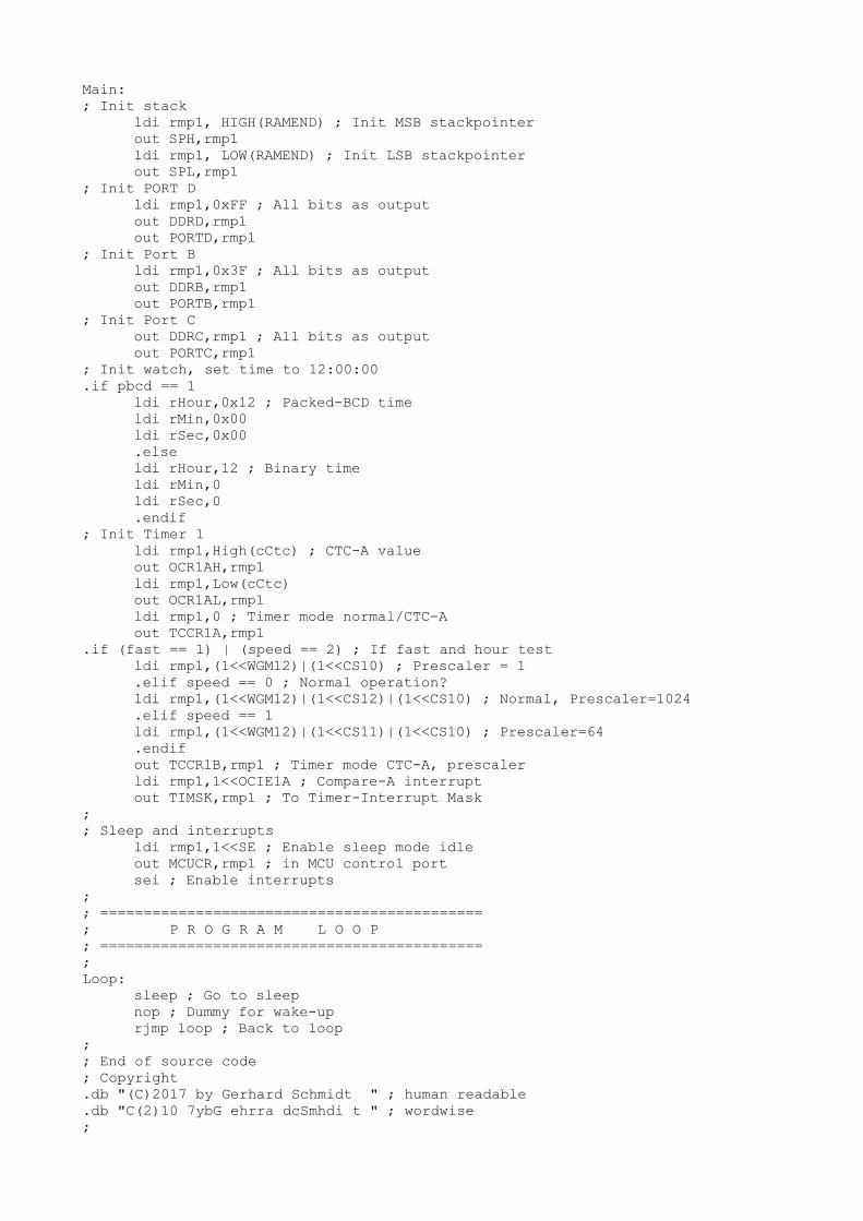
Main:; Init stack
ldi rmp1, HIGH(RAMEND) ; Init MSB stackpointerout SPH,rmp1ldi rmp1, LOW(RAMEND) ; Init LSB stackpointerout SPL,rmp1
; Init PORT Dldi rmp1,0xFF ; All bits as outputout DDRD,rmp1out PORTD,rmp1
; Init Port Bldi rmp1,0x3F ; All bits as outputout DDRB,rmp1out PORTB,rmp1
; Init Port Cout DDRC,rmp1 ; All bits as outputout PORTC,rmp1
; Init watch, set time to 12:00:00.if pbcd == 1
ldi rHour,0x12 ; Packed-BCD timeldi rMin,0x00ldi rSec,0x00.elseldi rHour,12 ; Binary timeldi rMin,0ldi rSec,0.endif
; Init Timer 1ldi rmp1,High(cCtc) ; CTC-A valueout OCR1AH,rmp1ldi rmp1,Low(cCtc)out OCR1AL,rmp1ldi rmp1,0 ; Timer mode normal/CTC-Aout TCCR1A,rmp1
.if (fast == 1) | (speed == 2) ; If fast and hour testldi rmp1,(1<<WGM12)|(1<<CS10) ; Prescaler = 1.elif speed == 0 ; Normal operation?ldi rmp1,(1<<WGM12)|(1<<CS12)|(1<<CS10) ; Normal, Prescaler=1024.elif speed == 1ldi rmp1,(1<<WGM12)|(1<<CS11)|(1<<CS10) ; Prescaler=64.endifout TCCR1B,rmp1 ; Timer mode CTC-A, prescalerldi rmp1,1<<OCIE1A ; Compare-A interruptout TIMSK,rmp1 ; To Timer-Interrupt Mask
;; Sleep and interrupts
ldi rmp1,1<<SE ; Enable sleep mode idleout MCUCR,rmp1 ; in MCU control portsei ; Enable interrupts
;; ============================================; P R O G R A M L O O P; ============================================;Loop:
sleep ; Go to sleepnop ; Dummy for wake-uprjmp loop ; Back to loop
;; End of source code; Copyright.db "(C)2017 by Gerhard Schmidt " ; human readable.db "C(2)10 7ybG ehrra dcSmhdi t " ; wordwise;