Embed Size (px)
Citation preview
USB pedalboard controller/audio interface for iOS, Mac, PC.
USER MANUAL
Contents
2
Table of ContentsContents 2
English 3Power adapter information 3iRig Stomp I/O 3Register your iRig Stomp I/O 41 Installation and setup 41.1 iOS Devices 41.2 MAC/PC 8
2 Operating modes 93 Live Mode 103.1 Using iRig Stomp I/O with AmpliTube 103.2 Preset mode 103.3 Stomp mode 123.4 Expression pedal 133.5 Looper 133.6 Tuner 143.7 Tap tempo 153.8 MIDI IN/OUT ports 15
4 Audio/MIDI interface and foot controller 154.1 Using iRig Stomp I/O as a generic MIDI controller 154.2 Default mode 164.3 Stomp mode 164.4 Expression pedal 174.5 Tap tempo 174.6 MIDI IN/OUT ports 17
5 Stand alone MIDI foot controller 185.1 Using iRig Stomp I/O as stand alone controller (no computer required) 18
6 Pedal calibration 187 External pedal inputs 188 Audio meters 189 Bootloader 1910 Specifications 19Warranty 20Support and more info 20
Regulatory 21
English
3
Power adapter informationUse only the specified AC adaptor you can buy at: www.ikmultimedia.com/irigpsu3aUse only the specified AC adaptor (iRig PSU 3A) and make sure the line voltage at the installation matches the input voltage specified on the AC adaptor’s body.IK Multimedia will not be responsible of any damage caused by usage of any AC adaptor other than the specified one (iRig PSU 3A).The usage of AC adaptors other than the specified one (iRig PSU 3A) could compromise the user experience in terms of:• Safety risk• Apple device charging performances• Noise performances
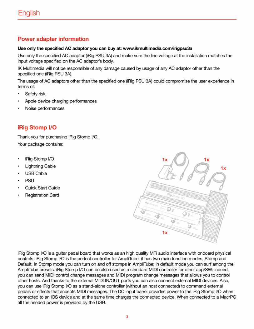
iRig Stomp I/OThank you for purchasing iRig Stomp I/O.Your package contains:
• iRig Stomp I/O• Lightning Cable• USB Cable• PSU• Quick Start Guide• Registration Card
iRig Stomp I/O is a guitar pedal board that works as an high quality MFi audio interface with onboard physical controls. iRig Stomp I/O is the perfect controller for AmpliTube: it has two main function modes, Stomp and Default. In Stomp mode you can turn on and off stomps in AmpliTube; in default mode you can surf among the AmpliTube presets. iRig Stomp I/O can be also used as a standard MIDI controller for other app/SW: indeed, you can send MIDI control change messages and MIDI program change messages that allows you to control other hosts. And thanks to the external MIDI IN/OUT ports you can also connect external MIDI devices. Also, you can use iRig Stomp I/O as a stand-alone controller (without an host connected) to command external pedals or effects that accepts MIDI messages. The DC input barrel provides power to the iRig Stomp I/O when connected to an iOS device and at the same time charges the connected device. When connected to a Mac/PC all the needed power is provided by the USB.
English
4
Register your iRig Stomp I/OBy registering, you can access technical support, activate your warranty and receive free JamPoints™ which will be added to your account. JamPoints™ allow you to obtain discounts on future IK purchases! Registering also keeps you informed of all the latest software updates and IK products. Register at: www.ikmultimedia.com/registration
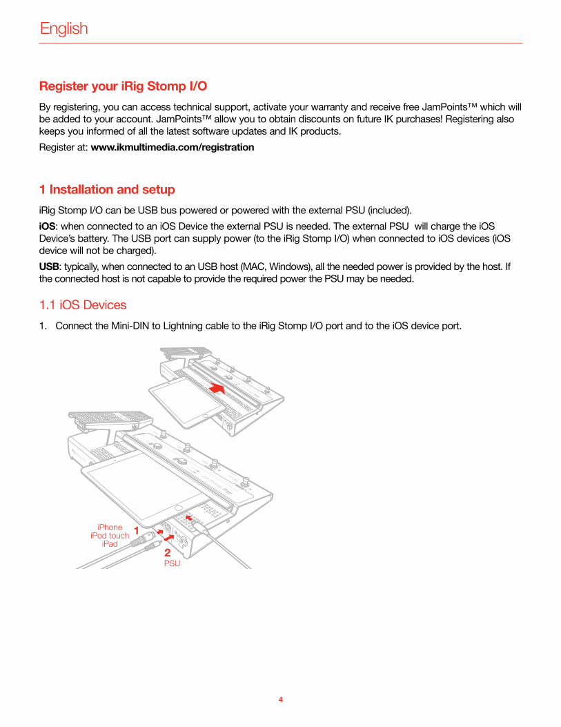
1 Installation and setupiRig Stomp I/O can be USB bus powered or powered with the external PSU (included).iOS: when connected to an iOS Device the external PSU is needed. The external PSU will charge the iOS Device’s battery. The USB port can supply power (to the iRig Stomp I/O) when connected to iOS devices (iOS device will not be charged).USB: typically, when connected to an USB host (MAC, Windows), all the needed power is provided by the host. If the connected host is not capable to provide the required power the PSU may be needed.
1.1 iOS Devices1. Connect the Mini-DIN to Lightning cable to the iRig Stomp I/O port and to the iOS device port.
English
5
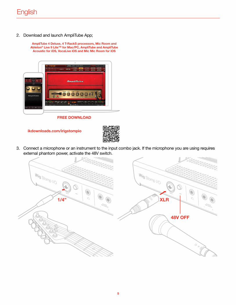
2. Download and launch AmpliTube App;
3. Connect a microphone or an instrument to the input combo jack. If the microphone you are using requires external phantom power, activate the 48V switch.
English
6
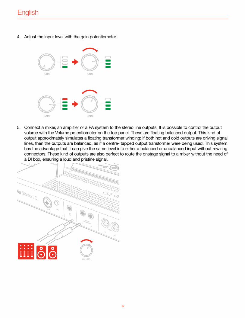
4. Adjust the input level with the gain potentiometer.
5. Connect a mixer, an amplifier or a PA system to the stereo line outputs. It is possible to control the output volume with the Volume potentiometer on the top panel. These are floating balanced output. This kind of output approximately simulates a floating transformer winding; if both hot and cold outputs are driving signal lines, then the outputs are balanced, as if a centre- tapped output transformer were being used. This system has the advantage that it can give the same level into either a balanced or unbalanced input without rewiring connectors. These kind of outputs are also perfect to route the onstage signal to a mixer without the need of a DI box, ensuring a loud and pristine signal.
English
7
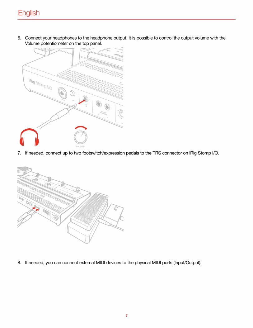
6. Connect your headphones to the headphone output. It is possible to control the output volume with the Volume potentiometer on the top panel.
7. If needed, connect up to two footswitch/expression pedals to the TRS connector on iRig Stomp I/O.
8. If needed, you can connect external MIDI devices to the physical MIDI ports (Input/Output).
English
8
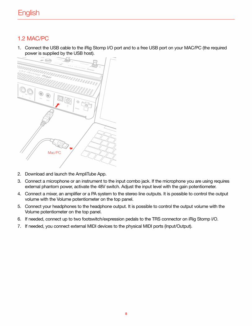
1.2 MAC/PC1. Connect the USB cable to the iRig Stomp I/O port and to a free USB port on your MAC/PC (the required
power is supplied by the USB host).
2. Download and launch the AmpliTube App.3. Connect a microphone or an instrument to the input combo jack. If the microphone you are using requires
external phantom power, activate the 48V switch. Adjust the input level with the gain potentiometer.4. Connect a mixer, an amplifier or a PA system to the stereo line outputs. It is possible to control the output
volume with the Volume potentiometer on the top panel.5. Connect your headphones to the headphone output. It is possible to control the output volume with the
Volume potentiometer on the top panel.6. If needed, connect up to two footswitch/expression pedals to the TRS connector on iRig Stomp I/O.7. If needed, you connect external MIDI devices to the physical MIDI ports (Input/Output).
English
9
2 Operating modes
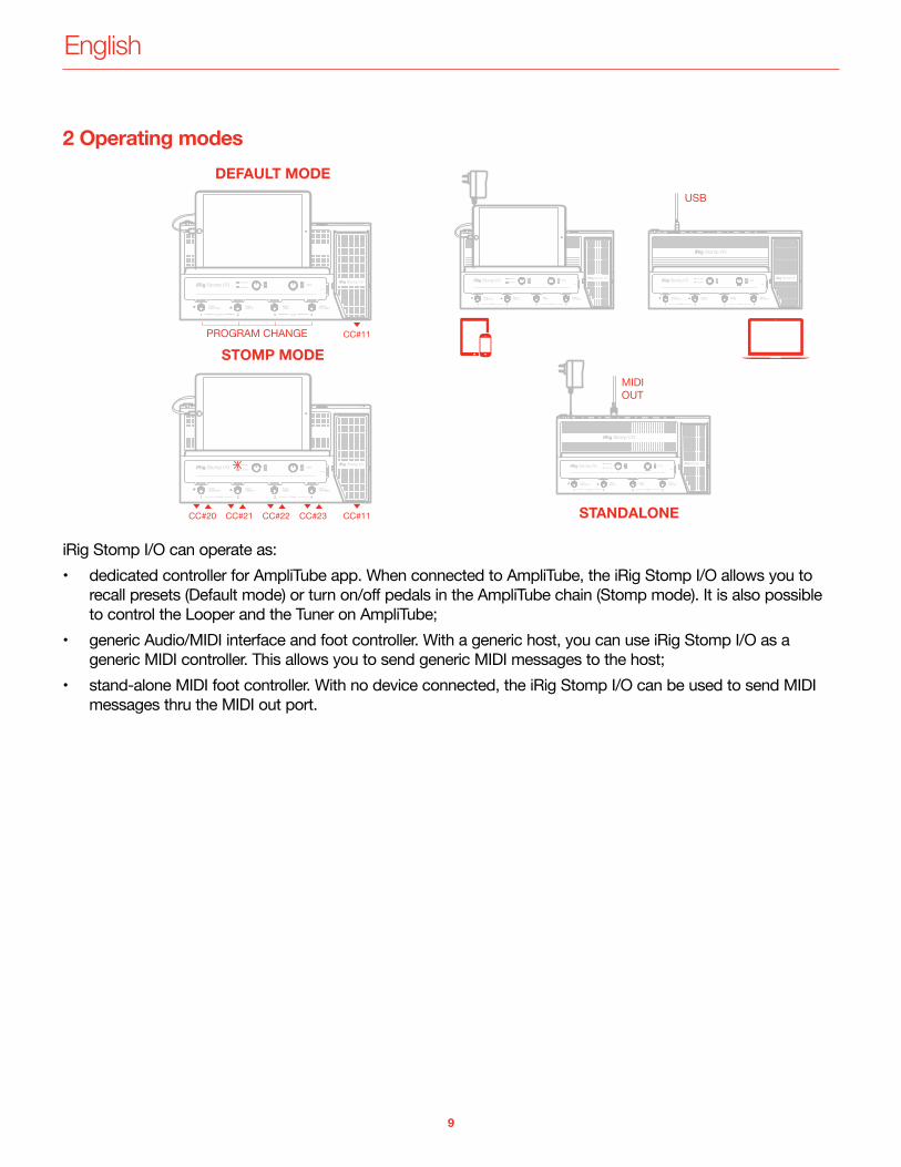
iRig Stomp I/O can operate as:• dedicated controller for AmpliTube app. When connected to AmpliTube, the iRig Stomp I/O allows you to
recall presets (Default mode) or turn on/off pedals in the AmpliTube chain (Stomp mode). It is also possible to control the Looper and the Tuner on AmpliTube;
• generic Audio/MIDI interface and foot controller. With a generic host, you can use iRig Stomp I/O as a generic MIDI controller. This allows you to send generic MIDI messages to the host;
• stand-alone MIDI foot controller. With no device connected, the iRig Stomp I/O can be used to send MIDI messages thru the MIDI out port.
English
10
3 Live Mode
3.1 Using iRig Stomp I/O with AmpliTubeWhen connected to a device running AmpliTube you can access to a full set of controls. Below we describe the operational mode when the app/software AmpliTube is running.USB MIDI portMake sure to have selected “iRig Stomp IO Control” as MIDI IN/OUT port.
3.2 Preset mode
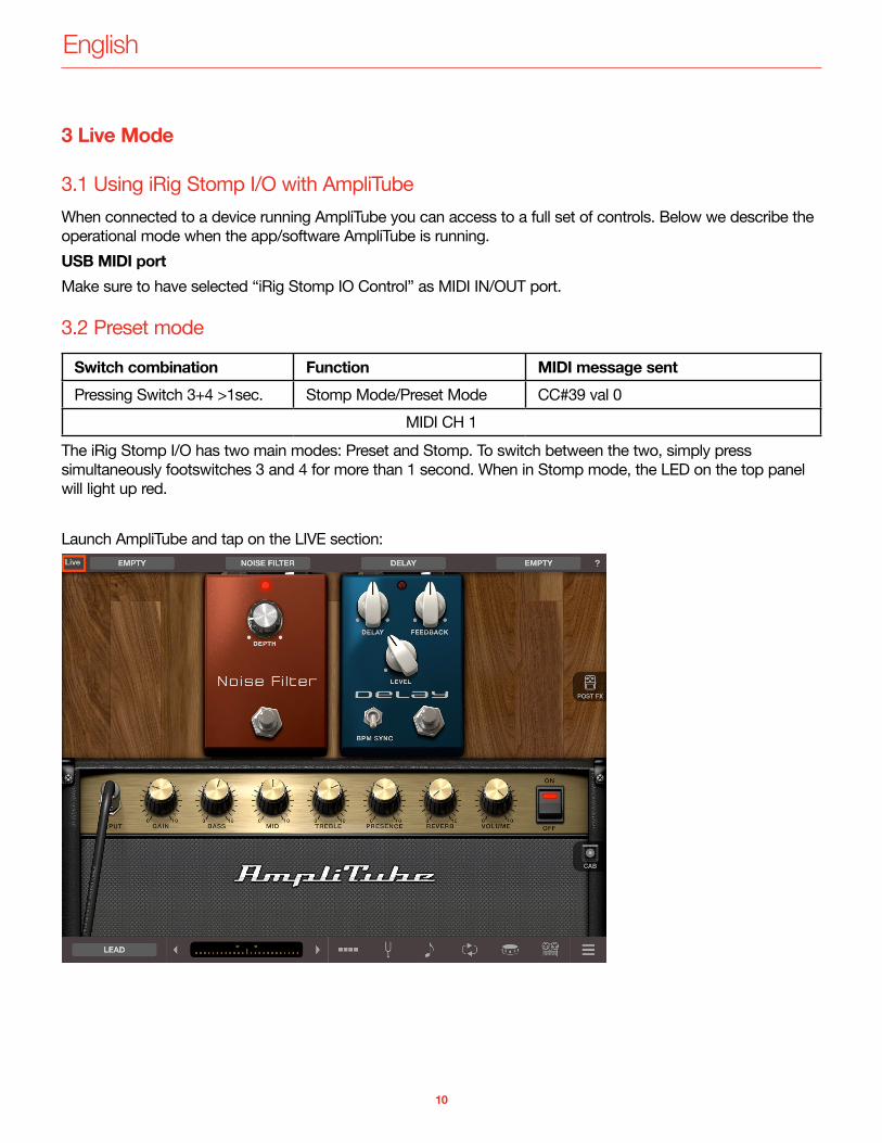
Switch combination Function MIDI message sentPressing Switch 3+4 >1sec. Stomp Mode/Preset Mode CC#39 val 0
MIDI CH 1The iRig Stomp I/O has two main modes: Preset and Stomp. To switch between the two, simply press simultaneously footswitches 3 and 4 for more than 1 second. When in Stomp mode, the LED on the top panel will light up red.
Launch AmpliTube and tap on the LIVE section:
English
11
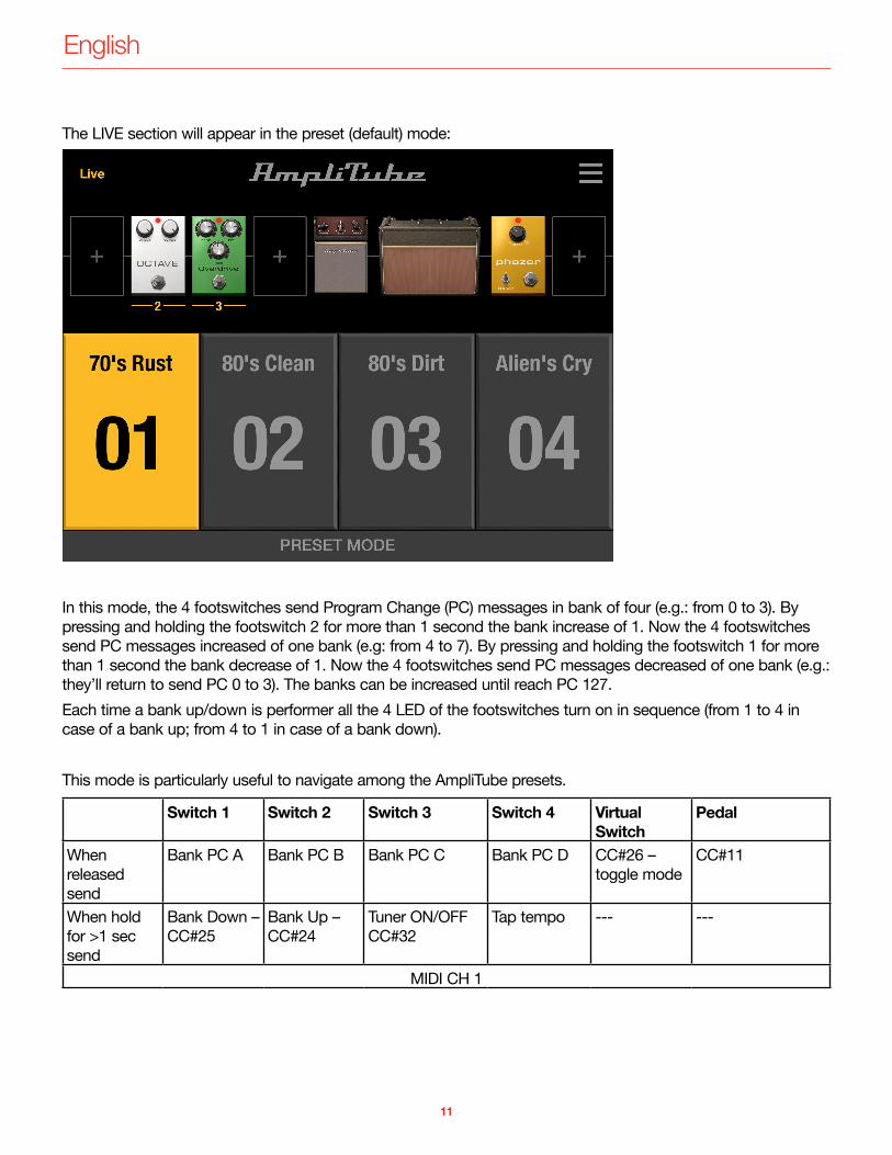
The LIVE section will appear in the preset (default) mode:
In this mode, the 4 footswitches send Program Change (PC) messages in bank of four (e.g.: from 0 to 3). By pressing and holding the footswitch 2 for more than 1 second the bank increase of 1. Now the 4 footswitches send PC messages increased of one bank (e.g: from 4 to 7). By pressing and holding the footswitch 1 for more than 1 second the bank decrease of 1. Now the 4 footswitches send PC messages decreased of one bank (e.g.: they’ll return to send PC 0 to 3). The banks can be increased until reach PC 127.Each time a bank up/down is performer all the 4 LED of the footswitches turn on in sequence (from 1 to 4 in case of a bank up; from 4 to 1 in case of a bank down).
This mode is particularly useful to navigate among the AmpliTube presets.
Switch 1 Switch 2 Switch 3 Switch 4 Virtual Switch
Pedal
When released send
Bank PC A Bank PC B Bank PC C Bank PC D CC#26 – toggle mode
CC#11
When hold for >1 sec send
Bank Down – CC#25
Bank Up – CC#24
Tuner ON/OFF CC#32
Tap tempo --- ---
MIDI CH 1
English
12
3.3 Stomp mode
Switch combination Function MIDI message sentPressing Switch 3+4 >1sec. Stomp Mode/Preset Mode CC#39 val 127
MIDI CH 1The iRig Stomp I/O has two main modes: Preset and Stomp. To switch between the two, simply press simultaneously footswitches 3 and 4 for more than 1 second. When in Stomp mode, the LED on the top panel will light up red.
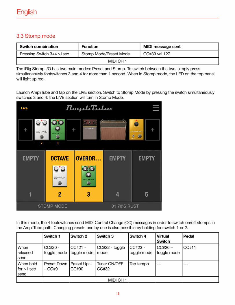
Launch AmpliTube and tap on the LIVE section. Switch to Stomp Mode by pressing the switch simultaneously switches 3 and 4: the LIVE section will turn in Stomp Mode.
In this mode, the 4 footswitches send MIDI Control Change (CC) messages in order to switch on/off stomps in the AmpliTube path. Changing presets one by one is also possible by holding footswitch 1 or 2.
Switch 1 Switch 2 Switch 3 Switch 4 Virtual Switch
Pedal
When released send
CC#20 - toggle mode
CC#21 - toggle mode
CC#22 - toggle mode
CC#23 - toggle mode
CC#26 – toggle mode
CC#11
When hold for >1 sec send
Preset Down – CC#91
Preset Up – CC#90
Tuner ON/OFF CC#32
Tap tempo --- ---
MIDI CH 1
English
13
The 5 footswitch’s LEDs show you the current status of the stomp’s slot in AmpliTube:
Empty slot LED offStomp off LED greenStomp on LED red
The footswitches 1 to 5 correspond to the first four slots in AmpliTube, plus the pedal slot. If the slot in AmpliTube is empty, corresponding LED is Off; if the slot have a stomp in it, but it is off, then the corresponding LED in On green; if the slot have a stomp in it, and it is on, then the corresponding LED in On red.
3.4 Expression pedalThe on-board expression pedal send a MIDI Control Change message (CC#11) and it can be used to control, for example, a Wah pedal inserted in the AmpliTube rig ; the virtual switch (CC#26) turns on/off the Wah pedal.When a Wah pedal is loaded in the AmpliTube rig, it will be automatically inserted in the slot n.5 and it will be controlled by the on-board expression pedal.
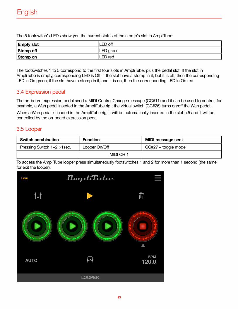
3.5 Looper
Switch combination Function MIDI message sentPressing Switch 1+2 >1sec. Looper On/Off CC#27 – toggle mode
MIDI CH 1To access the AmpliTube looper press simultaneously footswitches 1 and 2 for more than 1 second (the same for exit the looper).
English
14
When iRig Stomp I/O is in looper mode, the 4 footswitches act as:
Footswitch Function Message sentSW 1 Selects previous track CC#28 and CC#58 when holding for >1 sec.SW 2 Selects next track CC#29 and CC#59 when holding for >1 sec.SW 3 Start-Stop recording/stop playback
of the selected trackCC#30 and CC#60 when holding for >1 sec.
SW 4 (Holding for >1sec.) Delete selected track CC#31 and CC#61 when holding for >1 sec.MIDI CH 1
Footswitch LED 3 shows you the status of the track:
Function LED statusTrack armed LED blinking (red)Track in recording LED steady on (red)Track in playback LED steady on (green)Track empty LED offTrack recorded but not in playback
LED blinking (green)
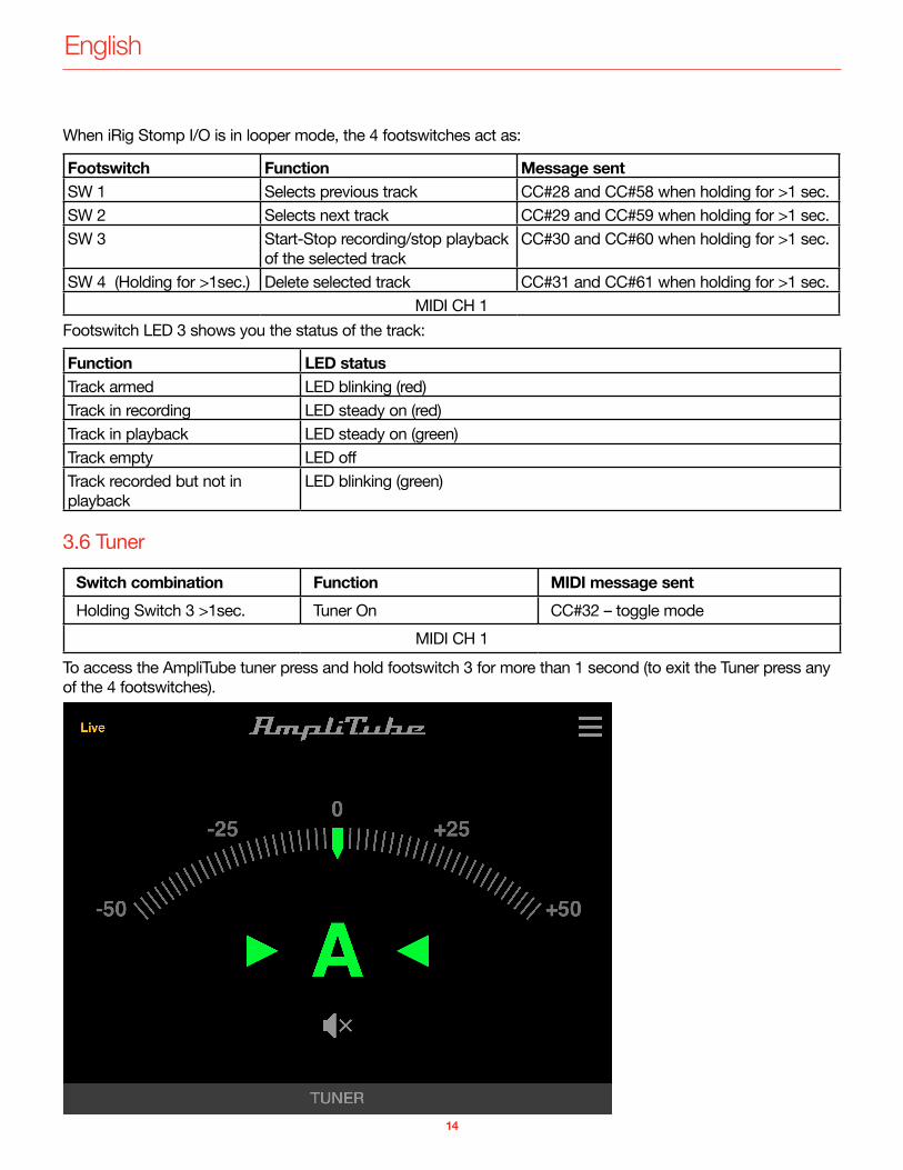
3.6 Tuner
Switch combination Function MIDI message sentHolding Switch 3 >1sec. Tuner On CC#32 – toggle mode
MIDI CH 1To access the AmpliTube tuner press and hold footswitch 3 for more than 1 second (to exit the Tuner press any of the 4 footswitches).
English
15
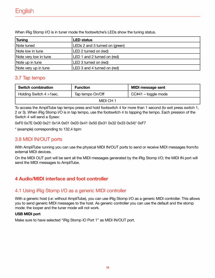
When iRig Stomp I/O is in tuner mode the footswitche’s LEDs show the tuning status.
Tuning LED statusNote tuned LEDs 2 and 3 turned on (green)Note low in tune LED 2 turned on (red)Note very low in tune LED 1 and 2 turned on (red)Note up in tune LED 3 turned on (red)Note very up in tune LED 3 and 4 turned on (red)
3.7 Tap tempo
Switch combination Function MIDI message sentHolding Switch 4 >1sec. Tap tempo On/Off CC#41 – toggle mode
MIDI CH 1To access the AmpliTube tap tempo press and hold footswitch 4 for more than 1 second (to exit press switch 1, 2 or 3). When iRig Stomp I/O is in tap tempo, use the footswitch 4 to tapping the tempo. Each pression of the Switch 4 will send a Sysex: 0xF0 0x7E 0x00 0x21 0x1A 0x01 0x03 0x41 0x50 (0x31 0x32 0x33 0x34)* 0xF7* (example) corresponding to 132,4 bpm
3.8 MIDI IN/OUT portsWith AmpliTube running you can use the physical MIDI IN/OUT ports to send or receive MIDI messages from/to external MIDI devices.On the MIDI OUT port will be sent all the MIDI messages generated by the iRig Stomp I/O; the MIDI IN port will send the MIDI messages to AmpliTube.
4 Audio/MIDI interface and foot controller
4.1 Using iRig Stomp I/O as a generic MIDI controllerWith a generic host (i.e: without AmpliTube), you can use iRig Stomp I/O as a generic MIDI controller. This allows you to send generic MIDI messages to the host. As generic controller you can use the default and the stomp mode: the looper and the tuner mode will not work.USB MIDI portMake sure to have selected “iRig Stomp IO Port 1” as MIDI IN/OUT port.
English
16
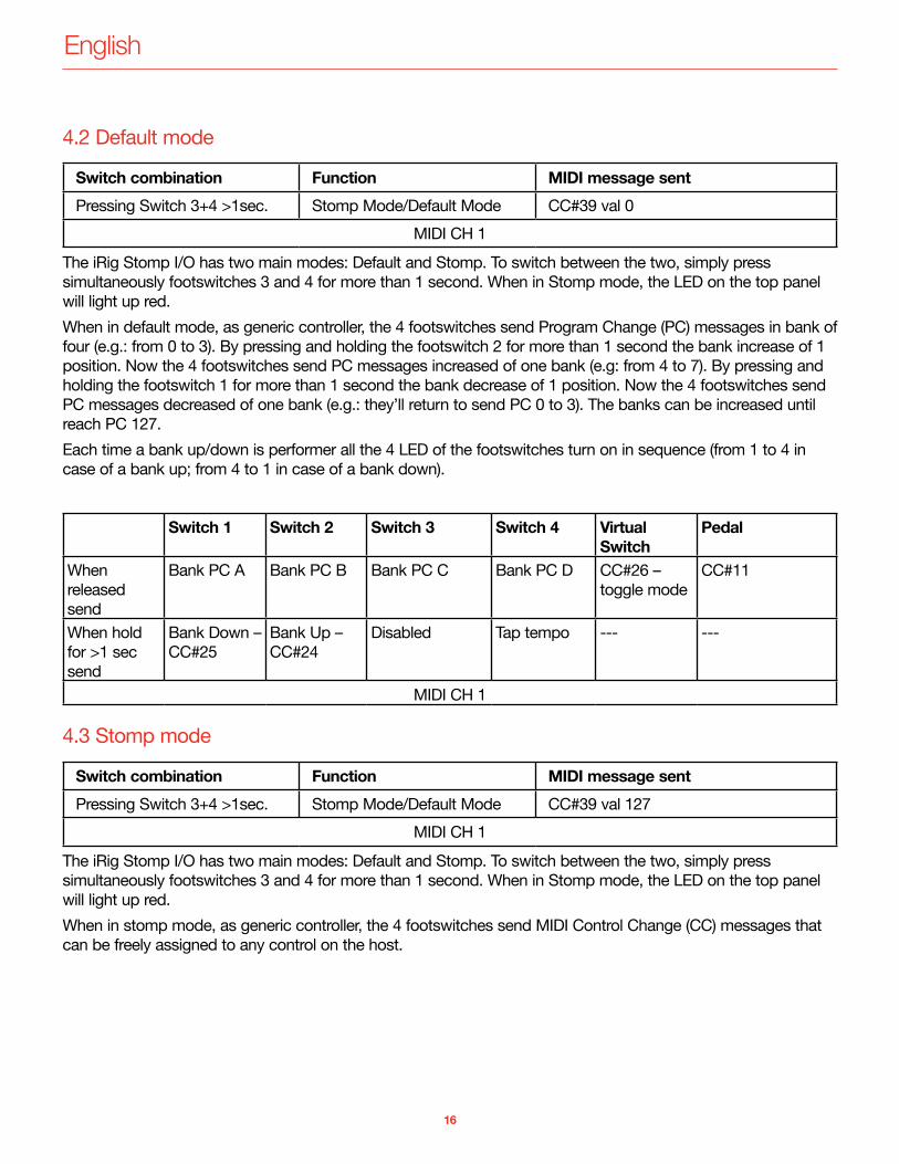
4.2 Default mode
Switch combination Function MIDI message sentPressing Switch 3+4 >1sec. Stomp Mode/Default Mode CC#39 val 0
MIDI CH 1The iRig Stomp I/O has two main modes: Default and Stomp. To switch between the two, simply press simultaneously footswitches 3 and 4 for more than 1 second. When in Stomp mode, the LED on the top panel will light up red.When in default mode, as generic controller, the 4 footswitches send Program Change (PC) messages in bank of four (e.g.: from 0 to 3). By pressing and holding the footswitch 2 for more than 1 second the bank increase of 1 position. Now the 4 footswitches send PC messages increased of one bank (e.g: from 4 to 7). By pressing and holding the footswitch 1 for more than 1 second the bank decrease of 1 position. Now the 4 footswitches send PC messages decreased of one bank (e.g.: they’ll return to send PC 0 to 3). The banks can be increased until reach PC 127.Each time a bank up/down is performer all the 4 LED of the footswitches turn on in sequence (from 1 to 4 in case of a bank up; from 4 to 1 in case of a bank down).
Switch 1 Switch 2 Switch 3 Switch 4 Virtual Switch
Pedal
When released send
Bank PC A Bank PC B Bank PC C Bank PC D CC#26 – toggle mode
CC#11
When hold for >1 sec send
Bank Down – CC#25
Bank Up – CC#24
Disabled Tap tempo --- ---
MIDI CH 1
4.3 Stomp mode
Switch combination Function MIDI message sentPressing Switch 3+4 >1sec. Stomp Mode/Default Mode CC#39 val 127
MIDI CH 1The iRig Stomp I/O has two main modes: Default and Stomp. To switch between the two, simply press simultaneously footswitches 3 and 4 for more than 1 second. When in Stomp mode, the LED on the top panel will light up red.When in stomp mode, as generic controller, the 4 footswitches send MIDI Control Change (CC) messages that can be freely assigned to any control on the host.
English
17
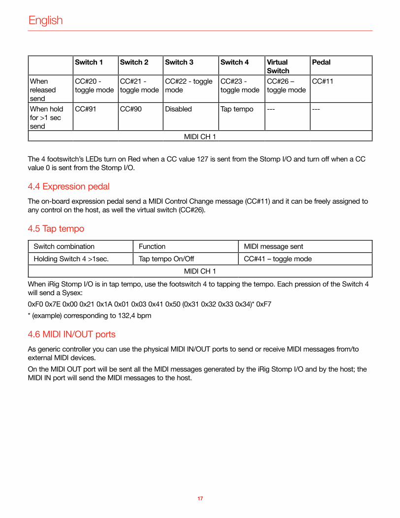
Switch 1 Switch 2 Switch 3 Switch 4 Virtual Switch
Pedal
When released send
CC#20 - toggle mode
CC#21 - toggle mode
CC#22 - toggle mode
CC#23 - toggle mode
CC#26 – toggle mode
CC#11
When hold for >1 sec send
CC#91 CC#90 Disabled Tap tempo --- ---
MIDI CH 1
The 4 footswitch’s LEDs turn on Red when a CC value 127 is sent from the Stomp I/O and turn off when a CC value 0 is sent from the Stomp I/O.
4.4 Expression pedalThe on-board expression pedal send a MIDI Control Change message (CC#11) and it can be freely assigned to any control on the host, as well the virtual switch (CC#26).
4.5 Tap tempo
Switch combination Function MIDI message sentHolding Switch 4 >1sec. Tap tempo On/Off CC#41 – toggle mode
MIDI CH 1When iRig Stomp I/O is in tap tempo, use the footswitch 4 to tapping the tempo. Each pression of the Switch 4 will send a Sysex: 0xF0 0x7E 0x00 0x21 0x1A 0x01 0x03 0x41 0x50 (0x31 0x32 0x33 0x34)* 0xF7* (example) corresponding to 132,4 bpm
4.6 MIDI IN/OUT portsAs generic controller you can use the physical MIDI IN/OUT ports to send or receive MIDI messages from/to external MIDI devices.On the MIDI OUT port will be sent all the MIDI messages generated by the iRig Stomp I/O and by the host; the MIDI IN port will send the MIDI messages to the host.
English
18
5 Stand alone MIDI foot controller
5.1 Using iRig Stomp I/O as stand alone controller (no computer required)With no device connected, the iRig Stomp I/O can be used to send MIDI messages thru the MIDI OUT port. Messages sent are the same of generic MIDI controller, but all the MIDI messages are routed to the MIDI OUT port.To use the iRig Stomp I/O as a stand alone controller, keep pressed the footswitch 1 while connecting the external PSU: to indicate that iRig Stomp I/O has been initialized in stand alone mode, all the 4 footswitch’s LEDs blink red 3 times and the red LEDs of the meters turn on red.In this mode, all the message sent are the same as per paragraph 4 of this manual (Audio/MIDI interface and foot controller), with exception of the tap tempo message that’s not sent. The unit will start up in this mode each time it will be powered on: to exit the stand alone mode keep pressed footswitch 1 while connecting the external PSU.
6 Pedal calibrationThe on-board expression pedal is factory calibrated to offer the best experience. Nevertheless, a user pedal calibration may be required. Before to perform the pedal calibration, bring the pedal to its minimum position. To start the calibration process keep pressed the footswitch 3 while powering up iRig Stomp I/O. When the iRig Stomp I/O is in pedal calibration the pedal’s LED blink alternatively in red and green: move the expression pedal from its minimum to its maximum (please note that the calibration does not consider the virtual switch). To end the calibration, press any of the footswitches: if the calibration ended up successfully the pedal’s LED blinks for few seconds green, otherwise it will blinks for few seconds red to indicate that something gone wrong during the procedure.
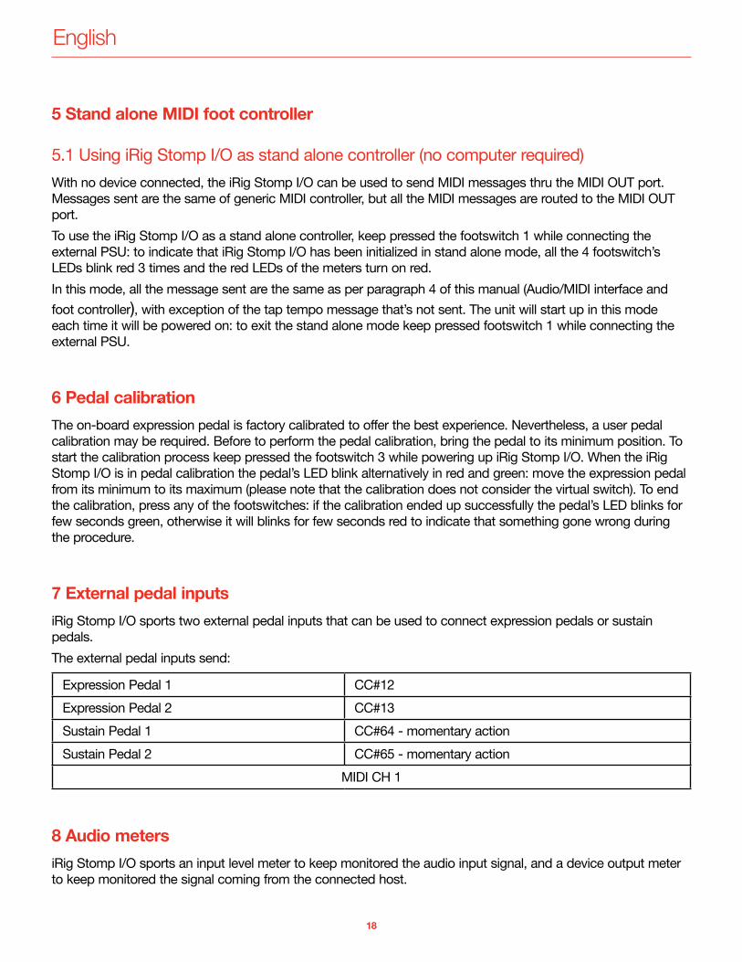
7 External pedal inputsiRig Stomp I/O sports two external pedal inputs that can be used to connect expression pedals or sustain pedals.The external pedal inputs send:
Expression Pedal 1 CC#12Expression Pedal 2 CC#13Sustain Pedal 1 CC#64 - momentary actionSustain Pedal 2 CC#65 - momentary action
MIDI CH 1
8 Audio metersiRig Stomp I/O sports an input level meter to keep monitored the audio input signal, and a device output meter to keep monitored the signal coming from the connected host.
English
19
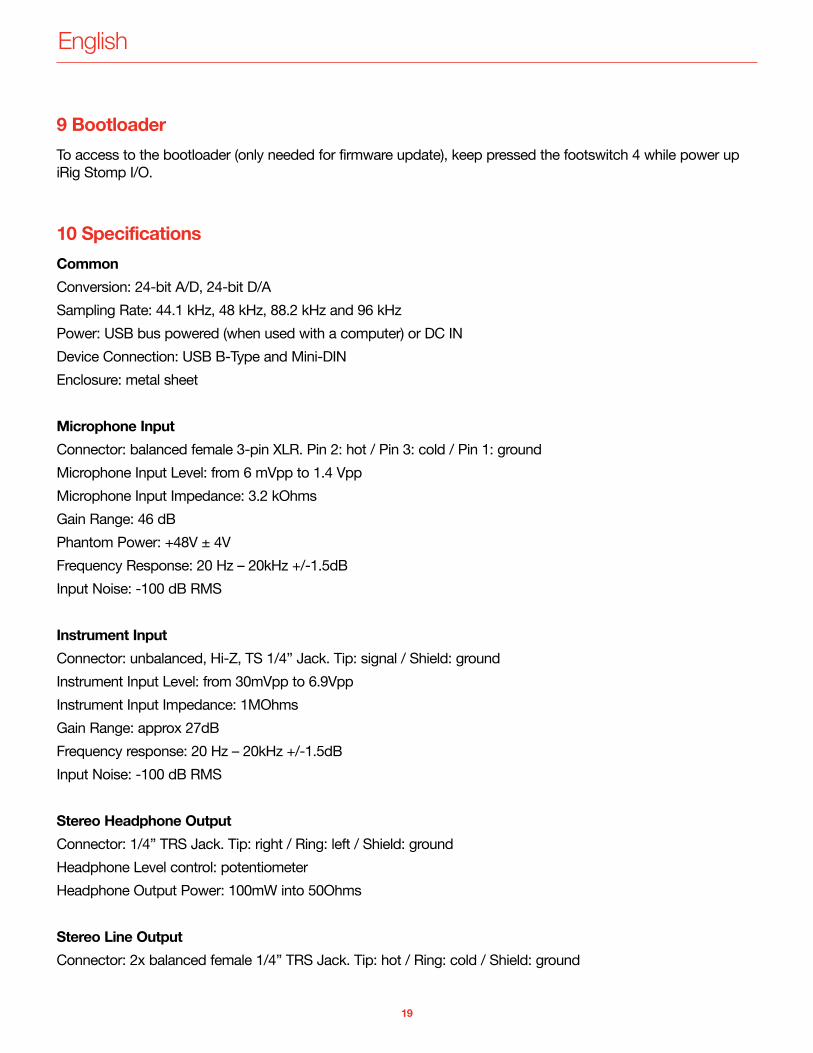
9 BootloaderTo access to the bootloader (only needed for firmware update), keep pressed the footswitch 4 while power up iRig Stomp I/O.
10 SpecificationsCommonConversion: 24-bit A/D, 24-bit D/ASampling Rate: 44.1 kHz, 48 kHz, 88.2 kHz and 96 kHzPower: USB bus powered (when used with a computer) or DC INDevice Connection: USB B-Type and Mini-DINEnclosure: metal sheet
Microphone InputConnector: balanced female 3-pin XLR. Pin 2: hot / Pin 3: cold / Pin 1: groundMicrophone Input Level: from 6 mVpp to 1.4 VppMicrophone Input Impedance: 3.2 kOhmsGain Range: 46 dBPhantom Power: +48V ± 4VFrequency Response: 20 Hz – 20kHz +/-1.5dBInput Noise: -100 dB RMS
Instrument InputConnector: unbalanced, Hi-Z, TS 1/4” Jack. Tip: signal / Shield: groundInstrument Input Level: from 30mVpp to 6.9VppInstrument Input Impedance: 1MOhmsGain Range: approx 27dBFrequency response: 20 Hz – 20kHz +/-1.5dBInput Noise: -100 dB RMS
Stereo Headphone OutputConnector: 1/4” TRS Jack. Tip: right / Ring: left / Shield: groundHeadphone Level control: potentiometerHeadphone Output Power: 100mW into 50Ohms
Stereo Line OutputConnector: 2x balanced female 1/4” TRS Jack. Tip: hot / Ring: cold / Shield: ground
English
20
Maximum Output Level: +13 dBu into 600 Ohms balanced loadFrequency Response: from 10 Hz to 21 kHz (+/- 0.2dB)Output Dynamic Range: 102 dB(A)Output Impedance: 150 Ohms balancedFloating Balanced Outputs
MIDI Input/OutputConnector: 2x 5-pin DIN
WarrantyPlease visit:www.ikmultimedia.com/warrantyfor the complete warranty policy.
Support and more infowww.ikmultimedia.com/supportwww.irigstompio.comApple is not responsible for the operation of this device or its compliance with safety and regulatory standards.
21
Regulatory
2018/04/10
“Made for iPod,” “Made for iPhone,” and “Made for iPad” mean that an electronic accessory has been designed to connect specifically to iPod, iPhone, or iPad, respectively, and has been certified by the developer to meet Apple performance standards. Apple is not responsible for the operation of this device or its compliance with safety and regulatory standards. Please note that the use of this accessory with iPod, iPhone, or iPad may affect wireless performance.iRig® Stomp I/O, iGrand Piano™ and SampleTank® are trademarks property of IK Multimedia Production Srl. All other product names and images, trademarks and artists names are the property of their respective owners, which are in no way associated or affiliated with IK Multimedia. iPad, iPhone, iPod touch Mac and Mac logo are trademarks of Apple Computer, Inc., registered in the U.S. and other countries. Lightning is a trademark of Apple Inc. App Store is a service mark of Apple Inc.
FCC statement
This device complies with Part 15.107 and 15.109 Class B of the FCC Rules CFR47: October 2010. Operation is subject to the following two conditions:
1. This device may not cause harmful interference.2. This device must accept any interference received, including interference that may cause undesired operation.
Changesormodificationsnotexpresslyapprovedbythepartyresponsibleforcompliance could void the user’s authority to operate the equipment.