Embed Size (px)
Citation preview

This manual MUST be given to the user of the product.
BEFORE using this product, read this manual and save for future runderstand the warnings, cautions or instructions, contact a healthcatechnical personnel before attempting to use this equipment
For more information regarding bed rail safety, refer to the Bed REntrapment Risk Notification Guide at www.invacare.com.
Invacare® G5510 Bed Full Electric Bed
User Manual
eference.If you are unable to re professional, dealer or
EN
ail
IMPORTANT SAFETY INSTRUCTIONSSAVE THESE INSTRUCTIONS

© 2013 Invacare Corporation. All rights reserved. Republication, duplication or modification in whole or in part is prohibited without prior written permission from Invacare. Trademarks are identified by ™ and ®. All trademarks are owned by or licensed to Invacare Corporation or its subsidiaries unless otherwise noted.Sherwin-Williams is a registered trademark of Sherwin-Williams.
Updated versions of this manual are available at www.invacare.com
Invacare® G5510 Bed 2 Part No 1180159

CONTENTS
1 GENERAL 5
Symbols .................................................................................................................................................................................................................................................... 5Symbols Used on Bed ........................................................................................................................................................................................................................... 6Symbols Used on Packaging................................................................................................................................................................................................................. 7Limited Warranty .................................................................................................................................................................................................................................. 8
2 OVERVIEW 9
Label Locations....................................................................................................................................................................................................................................... 9Typical Product Parameters .............................................................................................................................................................................................................. 11Accessories and Accessory Weight ................................................................................................................................................................................................ 13Optional Touch-up Paint.................................................................................................................................................................................................................... 14
3 SAFETY 15
General Guidelines .............................................................................................................................................................................................................................. 154 EMC INFORMATION 30
Electromagnetic Compatibility (EMC) Information .................................................................................................................................................................... 305 OPERATION 32
Operation Verification........................................................................................................................................................................................................................ 34Operating the Bed ............................................................................................................................................................................................................................... 35Operating the Locking Function on the Locking Caster ............................................................................................................................................................ 36Electrical Connections ........................................................................................................................................................................................................................ 36Installing/Removing Pendent and/or Port Cover.......................................................................................................................................................................... 37Using the Emergency Crank.............................................................................................................................................................................................................. 39Optional Bed Rails ............................................................................................................................................................................................................................... 40
6 DEALER SECTION - PACKAGING, HANDLING, AND SET-UP 41
Part No 1180159 3 Invacare® G5510 Bed

CONTENTS
Unpacking and Handling ..................................................................................................................................................................................................................... 41Set-Up..................................................................................................................................................................................................................................................... 43Assembling the Bed Ends ................................................................................................................................................................................................................... 48Electrical Connections ........................................................................................................................................................................................................................ 53Installing/Removing Mattress Keepers. ........................................................................................................................................................................................... 54
Connect Power Supply ............................................................................................................................................................................................ 55Storing the Bed..................................................................................................................................................................................................................................... 56
7 TROUBLESHOOTING/MAINTENANCE - USER/DEALER 58
Troubleshooting Electrical ................................................................................................................................................................................................................. 58Troubleshooting Mechanical ............................................................................................................................................................................................................. 60
8 MAINTENANCE AND CLEANING 62
Maintenance Checklist ........................................................................................................................................................................................................................ 62Cleaning the Beds ................................................................................................................................................................................................................................ 63
Invacare® G5510 Bed 4 Part No 1180159

1 GENERAL
1 General
1.1 Symbols
WarningsSignal words are used in this manual and apply to hazards or unsafe practices which could result in personal injury or property damage. See the information below for definitions of the signal words.
DANGERDanger indicates an imminently hazardous situation which, if not avoided, will result in death or serious injury.
WARNINGWarning indicates a potentially hazardous situation which, if not avoided, could result in death or serious injury.
CAUTIONCaution indicates a potentially hazardous situation which, if not avoided, may result in property damage or minor injury or both.
IMPORTANTIndicates a hazardous situation that could result in damage to property if it is not avoided.
Gives useful tips, recommendations and information for efficient, trouble-free use.
Part No 1180159 5 Invacare® G5510 Bed

1 GENERAL1.2 Symbols Used on Bed
General Warning Symbol (ISO 7010-W001)
Flammable Material Symbol (ISO 7010 - W021)
EIP Pollution Control Mark(China RoHS)
Degree of protection against electrical shock. Type BF equipment.
IP66
International Protection Code. Degree of protection against solid foreign objects and ingress of water.
READ and Understand the User Manual before using the bed.(ISO 7010 - M002)
WEEEDirective2002/96/EC
Type of protection against electrical shock. Class II, Double Insulation.
Explosive Material, explosion hazard symbol (ISO 7010 - W002)
General Mandatory Action Symbol (ISO 7010 - M001)
UL Recognized Component in U.S. and Canada
Alternating Current
Safe Working LoadThe combined weight of the patient, visitors, mattress, bedding and all accessories MUST not exceed rated capacity of safe working load.
Maximum Patient Weight
EC DirectiveCompliant
Protective Conductor
Terminal
Intertek’s ETL Listed Mark for US. A product bearing the ETL Listed Mark is determined to have met the minimum requirements of prescribed product safety standards.
General Prohibition Symbol (ISO 7010 - P001)
C - Tick(Australian EMC)
IEC 60417 - 5957For Indoor Use Only
Invacare® G5510 Bed 6 Part No 1180159

1 GENERAL
1.3 Symbols Used on Packaging
ISO 7000 - 0623TOP
ISO 7000 - 0621FRAGILE
ISO 7000 - 0626KEEP DRY
ISO 7000 - 2403DO NOT STACK OVER 2 HIGH
ISO 7000 - 0632PERMITTED TEMPERATURE RANGE
ISO 7000 - 2620PERMITTED HUMIDITY AREA
UP Button - Raises the Head Section
DOWN Button - Lowers the Head Section
Symbol for action to be made to the Head section
UP Button - Raises the Foot Section
DOWN Button - Lowers the Foot Section
Symbol for action to be made to the Foot section.
UP Button - Raises the entire mattress support platform
DOWN Button - Lowers the entire mattress support platform.
Symbol for action to be made raising the entire mattress support platform
0%
MAX
Part No 1180159 7 Invacare® G5510 Bed

1 GENERAL1.4 Limited WarrantyPLEASE NOTE: THE WARRANTY BELOW HAS BEEN DRAFTED TO COMPLY WITH FEDERAL LAW APPLICABLE TO PRODUCTS MANUFACTURED AFTER JULY 4, 1975.This warranty is extended only to the original purchaser who purchases this product when new and unused from Invacare or a dealer. This warranty is not extended to any other person or entity and is not transferable or assignable to any subsequent purchaser or owner. Coverage under this warranty will end upon any such subsequent sale or other transfer of title to any other person.This warranty gives you specific legal rights and you may also have other legal rights which vary from state to state.Invacare warrants the mechanical and electrical components of this product when purchased new and unused to be free from defects in materials and workmanship for a period of two years from date of purchase from Invacare or a dealer, with a copy of the seller’s invoice required for coverage under this warranty. Invacare warrants all welds of this product when purchased new and unused to be free from defects in materials and workmanship for a period of five years from date of purchase from Invacare or a dealer, with a copy of the seller’s invoice required for coverage under this warranty. If within such warranty period any such product shall be proven to be defective, such product shall be repaired or replaced, at Invacare's option, with refurbished or new parts. This warranty does not include any labor or shipping charges incurred in replacement part installation or repair of any such product. Product repairs shall not extend this warranty - coverage for repaired product shall end when this limited warranty terminates. Invacare's sole obligation and your exclusive remedy under this warranty shall be limited to such repair and/or replacement.For warranty service, please contact the dealer from whom you purchased your Invacare product. In the event you do not receive satisfactory warranty service, please write directly to Invacare at the address on the back cover, provide dealer's name, address, and the date of purchase, indicate nature of the defect and, if the product is serialized, indicate the serial number. Do not return products to our factory without our prior consent.LIMITATIONS AND EXCLUSIONS: THE FOREGOING WARRANTY SHALL NOT APPLY TO SERIAL NUMBERED PRODUCTS IF THE SERIAL NUMBER HAS BEEN REMOVED OR DEFACED, PRODUCTS SUBJECTED TO NEGLIGENCE, ACCIDENT, IMPROPER OPERATION, MAINTENANCE OR STORAGE, PRODUCTS MODIFIED WITHOUT INVACARE'S EXPRESS WRITTEN CONSENT (INCLUDING, BUT NOT LIMITED TO, MODIFICATION THROUGH THE USE OF UNAUTHORIZED PARTS OR ATTACHMENTS; PRODUCTS DAMAGED BY REASON OF REPAIRS MADE TO ANY COMPONENT WITHOUT THE SPECIFIC CONSENT OF INVACARE, OR TO A PRODUCT DAMAGED BY CIRCUMSTANCES BEYOND INVACARE'S CONTROL, AND SUCH EVALUATION WILL BE SOLELY DETERMINED BY INVACARE. THE WARRANTY SHALL NOT APPLY TO NORMAL WEAR AND TEAR OR FAILURE TO ADHERE TO THE PRODUCT INSTRUCTIONS.THE FOREGOING EXPRESS WARRANTY IS EXCLUSIVE AND IN LIEU OF ANY OTHER WARRANTIES WHATSOEVER, WHETHER EXPRESS OR IMPLIED, INCLUDING THE IMPLIED WARRANTIES OF MERCHANTABILITY AND FITNESS FOR A PARTICULAR PURPOSE, AND THE SOLE REMEDY FOR VIOLATIONS OF ANY WARRANTY WHATSOEVER, SHALL BE LIMITED TO REPAIR OR REPLACEMENT OF THE DEFECTIVE PRODUCT PURSUANT TO THE TERMS CONTAINED HEREIN. THE APPLICATION OF ANY IMPLIED WARRANTY WHATSOEVER SHALL NOT EXTEND BEYOND THE DURATION OF THE EXPRESS WARRANTY PROVIDED HEREIN. INVACARE SHALL NOT BE LIABLE FOR ANY CONSEQUENTIAL OR INCIDENTAL DAMAGES WHATSOEVER.SOME STATES DO NOT ALLOW THE EXCLUSION OR LIMITATION OF INCIDENTAL OR CONSEQUENTIAL DAMAGE, OR LIMITATION OF HOW LONG AN IMPLIED WARRANTY LASTS, SO THE ABOVE EXCLUSION AND LIMITATION MAY NOT BE APPLICABLE.
THIS WARRANTY SHALL BE EXTENDED TO COMPLY WITH STATE/PROVINCIAL LAWS AND REQUIREMENTS.
Invacare® G5510 Bed 8 Part No 1180159

2 OVERVIEW
2 Overview
2.1 Label Locations
Close cover when not in use. Otherwise, personal injurymay occur.
P/N 1180192Rev B
p/n 1180137 Rev D
p/n 1171783 Rev D
p/n 1180180 Rev C
p/n 1180192 Rev B
p/n 1180195 Rev D(Located on both bed ends)
p/n 1180201 Rev C
p/n 1180137 Rev D
= 700 lbs(317 kg) = 600 lbs
(272 kg)
SAFE WORKING LOAD MAX PATIENT WEIGHTBefore using the bed, read and understand the User Manual. The user manual provides proper operation and safe practices.Documentation can be obtained at:• www.invacare.com • ph (440) 329-6000 • One Invacare Way, Elyria OH 44036-2125 IP66
The combined weight of the patient, mattress, and accessories must not exceed safe working load.
Duty Cycle: Max 10%, max 2min/18min
Bed accessories designed by other manufacturers have NOT been tested by Invacare. Use of NON-Invacare bed accessories may result in injury or death.Use ONLY Invacare rails, mattresses, bed extenders, and other accessories with Invacare bed products.
DANGER: RISK OF INJURY OR DEATH
p/n 1180206 Rev B
p/n 1180206 Rev B
The bed MUST be in its lowest position when the patient is left unattended.
p/n 1180195 Rev D
C
p/n
1171
783
Rev
E
DO NOT use bed with flammable gases. Explosion may occur.
Only use nasal or mask oxygen delivery equipment. Otherwise, fire can occur.
Part No 1180159 9 Invacare® G5510 Bed

2 OVERVIEW
p/n 1171778 Rev B
Keep all electrical cords clear of moving parts.
Otherwise, damage may occur.
Keep all electrical cords clear of moving parts.
Otherwise, damage may occur.p/n 1171778 Rev B
p/n 1180193 Rev B
Before operating the bed, detach power
supply from the slat located under the bed. DO NOT place power
supply or other objects under the bed.
Before operating the bed, detach power
supply from the slat located under the bed. DO NOT place power
supply or other objects under the bed.
p/n 1180193 Rev B
p/n 1180199 Rev A
Remove pendent when not in use and store out of reach of children.
p/n 1180199 Rev A
Remove pendent when not in use and store out of reach of children.
These labels are located on the pendent cord. These labels are located on the power supply.
* p/n 1180191 Rev C
p/n 1171778 Rev B
p/n 1180199 Rev A p/n 1180193 Rev B
p/n 1171789 Rev D* This label is also located on the emergency crank.
p/n 1180191 Rev C
Before using the emergency crank on the bed, disconnect the pendent from the
bed. Otherwise, damage to the
actuator may occur.
Before using the emergency crank on the bed, disconnect the pendent from the
bed. Otherwise, damage to the
actuator may occur.p/n 1180191 Rev C
CLEANING INSTRUCTIONSSee Owner's Manual
INSTRUCTIONS POUR LE NETTOYAGESe référer au manuel de l'utilisateur
Consulter la panneau opposé pour la version en français canadien. P/N 1171789 Rev D
Refer to opposite side of label for English.
1. Unplug product before washing.2. Make sure all electrical parts are not damaged and that all connection ports are plugged.3. Disinfect and wash all components. 4. DO NOT power wash or steam clean. Use household water pressure. 5. Rinse thoroughly with water [maximum temperature 110° F (43° C)].6. Dry all components before storing.
P/N 1171789 Rev C
1. Débrancher le produit avant de le nettoyer.2. S'assurer que toutes les pièces électriques ne sont pas endommagées et que tous les ports des connexions sont fermés. 3. Désinfecter et nettoyer toutes les composantes.4. NE PAS utiliser d'appareil de nettoyage sous pression ou à vapeur. Utiliser l'eau de la maison.5. Rincer à fond avec de l'eau [empérature maximale de 110° F (43° C)] 6. Sécher toutes les composantes avant d'entreposer.
Invacare® G5510 Bed 10 Part No 1180159
2 OVERVIEW2.2 Typical Product Parameters
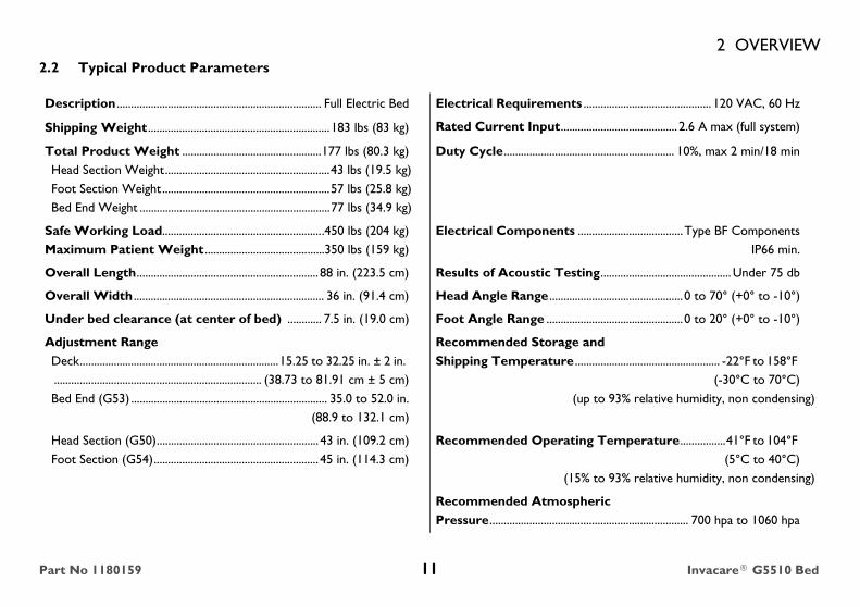
Description ........................................................................ Full Electric Bed Electrical Requirements ............................................. 120 VAC, 60 Hz
Shipping Weight ................................................................183 lbs (83 kg) Rated Current Input......................................... 2.6 A max (full system)
Total Product Weight .................................................177 lbs (80.3 kg)Head Section Weight..........................................................43 lbs (19.5 kg)Foot Section Weight ...........................................................57 lbs (25.8 kg)Bed End Weight ...................................................................77 lbs (34.9 kg)
Duty Cycle............................................................ 10%, max 2 min/18 min
Safe Working Load.........................................................450 lbs (204 kg)Maximum Patient Weight ..........................................350 lbs (159 kg)
Electrical Components .....................................Type BF ComponentsIP66 min.
Overall Length................................................................ 88 in. (223.5 cm) Results of Acoustic Testing..............................................Under 75 db
Overall Width ................................................................... 36 in. (91.4 cm) Head Angle Range ...............................................0 to 70° (+0° to -10°)
Under bed clearance (at center of bed) ............ 7.5 in. (19.0 cm) Foot Angle Range ................................................0 to 20° (+0° to -10°)
Adjustment RangeDeck......................................................................15.25 to 32.25 in. ± 2 in. ......................................................................... (38.73 to 81.91 cm ± 5 cm)Bed End (G53) ..................................................................... 35.0 to 52.0 in.
(88.9 to 132.1 cm)
Recommended Storage and Shipping Temperature ................................................... -22°F to 158°F
(-30°C to 70°C)(up to 93% relative humidity, non condensing)
Head Section (G50)......................................................... 43 in. (109.2 cm)Foot Section (G54).......................................................... 45 in. (114.3 cm)
Recommended Operating Temperature................41°F to 104°F (5°C to 40°C)
(15% to 93% relative humidity, non condensing)
Recommended Atmospheric Pressure...................................................................... 700 hpa to 1060 hpa
Part No 1180159 11 Invacare® G5510 Bed

2 OVERVIEWRegulatory Listing: ANSI/AAMI 60601-1 3rd Edition, ANSI/AAMI 60601-11, IEC 60601-2-52Application Environment 3-LTC - Long term care in a medical area where medical supervision is required and monitoring is provided, if necessary, and medical electrical equipment used in medical procedures may be provided to help maintain or improve the condition of the patient.
Application Environment 4 - Domestic - Care provided in a domestic area where medical electrical equipment is used to alleviate or compensate for an injury, disability, or disease.
Product DescriptionThe G5510 bed is a steel framed medical bed that allows for deck height adjustability and mattress deck articulation through the use of electronic actuators.The G5510 bed is for assisting in diagnosis, monitoring, prevention, treatment, alleviation of disease, or compensation for an injury or disability in an indoor environment.
Interaction of Patient with Bed
Invacare® G5510 Bed 12 Part No 1180159

2 OVERVIEW2.3 Accessories and Accessory Weight
DANGER!Risk of Injury or DamageImproper use of this product may cause injury or damage.
- If you are unable to understand the warnings, cautions, or instructions, contact a healthcare professional, dealer or technical personnel before attempting to use this equipment.
- DO NOT use this product or any available optional equipment without first completely reading and understanding these instructions and any additional instructional material such as user manuals, service manuals or instruction sheets supplied with this product or optional equipment..
The accessories in this table have been tested with the bed to meet the international bed standard IEC 60601-2-52:
DESCRIPTION MODEL NUMBER WEIGHT
BED RAIL, FULL LENGTH G29 26 lbs (11.8 kg)
MATTRESS SPS1080 23 lbs (10.4 kg)
TRAPEZE G7740CS 25 lbs (11.3 kg)
BED RAIL, HALF LENGTH
G30 29 lbs (13.1 kg)
Part No 1180159 13 Invacare® G5510 Bed

2 OVERVIEW
2.4 Optional Touch-up PaintSherwin-Williams®5A-58147 00(A)CODE 82XWHITE BIRCH2nd Dimension 5.0 Acrylic EnamelThis product can be purchased at Sherwin Williams Automotive paint branches only.
The accessories in this table have not been tested to the international bed standard IEC 60601-2-52. They have been tested to comply with Invacare standards.
DESCRIPTION MODEL NUMBER WEIGHT
MATTRESS 5180 20 lbs (9.1 kg)
5184 26 lbs (11.8 kg)
5185 30 lbs (13.6 kg)
5185XL 30 lbs (13.6 kg)
Solace Series, 23 - 31 lbs (10.4 - 14.1 kg) varies depending on model
microAir Series 17 - 56 (7.7 - 25.4 kg) varies depending on model
STOR A BED 5142 8 lbs (3.6 kg)
Invacare® G5510 Bed 14 Part No 1180159

3 SAFETY
3 SafetyThe Safety section contains important information for the safe operation and use of this product.
3.1 General Guidelines
DANGERRisk of Injury or DeathBed accessories designed by other manufacturers have NOT been tested by Invacare.Use of NON-Invacare bed accessories may result in injury or death.- Use ONLY Invacare rails, mattresses, bed extenders and other accessories with Invacare bed products.
WARNING!Risk of Injury or DamageImproper use of this product may cause injury or damage.
- If you are unable to understand the warnings, cautions, or instructions, contact a healthcare professional, dealer or technical personnel before attempting to use this equipment.
- DO NOT use this product or any available optional equipment without first completely reading and understanding these instructions and any additional instructional material such as user manuals, service manuals or instruction sheets supplied with this product or optional equipment..To avoid injury or product damage:Set-up and Assembly instructions MUST be performed by a qualified technician only. “Qualified Technician Only” sections are marked accordingly.
Part No 1180159 15 Invacare® G5510 Bed

3 SAFETY
WARNING!Risk of Injury or DamageContinued use of the bed with damaged parts could lead to the bed malfunctioning, causing injury to the user and/or caregiver.- Check all bed components and carton for damage, and test components before using. In case of damage, or if the bed is not working properly, contact a qualified technician or Invacare for repair.The Invacare G5510 Bed has been engineered to provide reliable operation. The bed has been thoroughly tested and inspected prior to shipment.Conditions such as restlessness, mental deterioration and dementia or seizure disorders (uncontrolled body movement), sleeping problems, and incontinence can also significantly impact a patient's risk of entrapment. Pediatric patients or patients with small body size may also have an increased risk of entrapment.
- Monitor patients with these conditions frequently.
The expected useful life of the G5510 bed is 5 years.Mattress platform, bed ends, pendent, and accessories are APPLIED PARTS.
NOTICETHE INFORMATION CONTAINED IN THIS DOCUMENT IS SUBJECT TO CHANGE WITHOUT NOTICE.
Invacare® G5510 Bed 16 Part No 1180159

3 SAFETY
The slats may take a relaxed position over time. This is normal and there is no compromise to the bed's structure. This is not a warranty issue.
The slats are designed as part of an integral sleep surface. Be careful not to stand on individual slats or drop on rigid objects as localized bending may occur.
DO NOT use the slats as a hand hold to assemble/disassemble or move the bed, otherwise the slats may bend resulting in permanent damage.
Disposal of Equipment and Accessories
Follow local governing ordinances and recycling plans regarding disposal of the device or components normally used in operation. The device does not generate waste or residue in operation. Any accessories not part of the device MUST be handled in accordance with the individual product marking for disposal.
Part No 1180159 17 Invacare® G5510 Bed

3 SAFETYElectrical
DANGERRisk of Death, Injury, or DamageShock hazards and risk of fire exist due to use of improper extension cord and use of three prong adapters.
- To avoid injury or product damage, when using an extension cord, use only an extension cord having at least 16 AWG (American Wire Gauge) wire and the same or higher electrical rating as the device being connected.
To reduce the risk of electric shock, this furnishing has a polarized plug (one blade is wider than the other). This plug will fit in a polarized outlet only one way.
- If the plug does not fit fully in the outlet, reverse the plug. If it still does not fit, contact a qualified electrician to install the proper outlet.
- DO NOT change the plug in any way
Protection to the user against electrical shock hazard is provided by using double insulated construction. Servicing a double-insulated product requires extreme care and knowledge of the system, and is to be done only by qualified service personnel. Replacement parts for a double-insulated product must be identical to the parts they replace. A double-insulated
product is marked with the words “DOUBLE INSULATION” or “DOUBLE INSULATED”. The symbol ( ) is also able to be marked on the product.
Invacare® G5510 Bed 18 Part No 1180159

3 SAFETYElectrical
WARNINGRisk of Injury or DamageTo avoid serious injury or product damage due to tripping hazards, strangulation hazards, and/or entangled, pinched, or severed cords:
- Ensure that all cord(s) are routed and secured properly.
To avoid injury or product damage:
- DO NOT open assemblies such as the motors, pendant, junction boxes or gear boxes. No user serviceable parts are inside. Contact dealer or Invacare for repair/replacement.
- Unplug the power cord from its power source before performing any maintenance on the electric bed.
WARNINGRisk of Injury or DamageTo avoid injury or damage from misuse:- ALWAYS position bed so that power cord is easy to access.- DO NOT unplug the power cord from the power supply. Damage to cord will result. Refer servicing to qualified personnel only.
Part No 1180159 19 Invacare® G5510 Bed

3 SAFETY
Entrapment Warning
Operating Information
CAUTIONRisk of DamageTo avoid damage to the power supply or the bed malfunctioning
- To prevent overheating, the power supply MUST not be covered during bed operation (i.e. pillows, blankets, etc.).
WARNINGRisk of Injury or DamageProper patient assessment and monitoring, and proper maintenance and use of equipment is required to reduce the risk of entrapment.Variations in bed rail dimensions, and mattress thickness, size or density could increase the risk of entrapment.
- Visit the FDA website at http://www.fda.gov to learn about the risks of entrapment. Review “A Guide to Bed Safety”, published by the Hospital Bed Safety Workgroup, located at www.invacare.com. Use the link located under each bed rail product entry to access this bed’s safety guide.
WARNINGRisk of Injury or DamageTo avoid electrical damage, product damage, shock and/or personal injury:
- Keep all bed components and accessories a minimum of 12 inches away from hot or heated surfaces.
Invacare® G5510 Bed 20 Part No 1180159

3 SAFETYOperating Information
WARNINGRisk of Injury or DamageContinued use of the bed with damaged parts could lead to the bed malfunctioning, causing injury to the user and/or caregiver.
- Check ALL bed components and carton for damage, and test components before use. In case of damage, or if the bed is not working properly, sontact a qualified technician or Invacare for repair.
- Before operating the bed, detach power supply from the slat located under the bed. Keeping the power supply attached to the slat may cause overheating resulting in the bed malfunctioning.
WARNINGRisk of Injury or DamageTo avoid pinching, crush and collapse hazards from bed deck contact with objects under the bed:
- Do not place any objects or let any individual underneath the bed or in between the raised bed frame components at any time.
To avoid choking from small detachable parts contained underneath the bed:
- Closely supervise children, pets, or people with physical/mental disabilities.
Part No 1180159 21 Invacare® G5510 Bed

3 SAFETYOperating Information
WARNINGRisk of Injury or DamageTo reduce the risk of electrical shock:
- When bed is not to be used for an extended period, unplug electric bed from the wall outlet.
- If a liquid is spilled in or around the electric bed, unplug the electric bed before cleaning. Clean up the spill and allow the electric bed or the area around the electric bed to dry thoroughly before using the electric controls again.
- If the unit is not working properly or is inoperable, call a qualified technician to examine the unit and repair it.
This bed is NOT designed to be used as a patient transport.
- When transporting a patient, use an approved patient transport.
Invacare® G5510 Bed 22 Part No 1180159

3 SAFETYOperating Information
WARNINGRisk of Injury or DamageTo avoid injury or damage when operating or moving the bed:
- Bed is only meant to be moved about patient room for cleaning or access purposes.
- Only use bed indoors
- DO NOT use near explosive gases - ALWAYS ensure that the individual utilizing the bed is positioned properly within the confines of the bed. DO NOT let any extremities protrude over the side or between the bed rails when performing these functions.- Make sure head and foot sections are connected securely to the bed ends before use.- The bed is equipped with locking casters. When transferring into or out of the bed, ALWAYS lock all 4 locking casters. Inspect the wheel locks for correct locking action before actual use. Even with casters properly locked, some flooring surfaces such as tile or wood, will allow the bed to move under some conditions. Use on surfaces such as these MUST be evaluated by the care providerTo avoid injury or damage from emergency crank when motor is on:- ALWAYS remove emergency crank(s) before performing electronic functions.
Part No 1180159 23 Invacare® G5510 Bed

3 SAFETY
WARNINGRisk of Injury or DamageTo avoid bed collapse and resulting injury or damage:- NEVER permit more than one person on the manual/electric bed at any time.- Evenly distribute body weight over the surface of the manual/electric bed.- DO NOT lay, sit or lean in such a way that your entire body weight is placed only on raised head or foot sections of the bed. This includes when repositioning or transferring into or out of bed.- DO NOT push on raised head or foot sections of the bed.- After this bed has been assembled, ALWAYS test to make sure that all sections of the bed are properly and securely in place before using.To avoid injury or damage from entanglement with bed components or bed collapse:
- Keep all moving parts, including the main frame, mattress deck, and all drive shafts, free of obstruction (i.e. blankets/sheets, tubing, wiring, cords, etc) during operation of the bed.
Invacare® G5510 Bed 24 Part No 1180159

3 SAFETYPendent Operation
WARNINGRisk of Injury or DamageA safety feature of this product includes protection against overheating caused by excessive or extended periods of operation. Depending on the duration, this includes multiple or repeated adjustments or the use of multiple functions at one time.
- To assure trouble free operation, ALWAYS allow a slight pause between multiple adjustments and avoid pressing more than one function button at a time.
- If thermal protection activation should occur, the bed will not respond to pendent commands. Given this situation, release the pendent button and allow the bed unit to sit for several minutes. This will allow the protection function time to reset and restore bed function. Depending on the severity of the initial overheating, this could take up to 30 minutes.
Pendent is constructed of latex-free materials.
Part No 1180159 25 Invacare® G5510 Bed

3 SAFETYRepair or Service Information
Replacement Parts/Accessories
WARNINGRisk of Injury or DamageTo avoid injury or damage:
DO NOT open assemblies such as the motors, pendent, power supply or gear boxes. No user serviceable parts are inside. Only qualified technicians are permitted to repair these parts. If unqualified individuals perform any work on these beds, the warranty is void.
Make sure connector locking caps are properly positioned and locked to the bus cable. Otherwise, spilled liquid may get into the electrical connection causing malfunctions to the electrical system.
DO NOT force the connector together, otherwise - injury or damage may occur.
Inspect the covering of the bed’s power supply and the patient pendent to assure that the covering is not cracked or damaged.
After any adjustments, repair or service and before use, make sure all attaching hardware is tightened securely. Unsecured parts could vibrate loose causing bed components to disengage causing injury and/or damage to the bed.
DANGERRisk of Injury or DamageTo avoid electrical shock, product damage and personal injury:
- Use masked or nasal type oxygen administering equipment only in conjunction with the electric bed. The use of ANYother type of oxygen administering equipment can result in a fire hazard.
- Equipment not suitable for use in the presence of flammable mixtures.
Invacare® G5510 Bed 26 Part No 1180159

3 SAFETY
WARNINGRisk of Injury or DamageALWAYS test to make sure that the bed rails are properly and securely in place before using the bed.
DO NOT use the bed rails as push handles for moving the bed.
WARNINGRisk of Injury or Damage- When used with an Invacare G5510 Bed, the bed rails DO NOT fall under any weight limitations. Bed rails can be deformed or broken if excessive side pressure is exerted on the bed rails. The bed rail is not an assist rail for getting into or out of bed. These bed rails are used for the purpose of preventing an individual from inadvertently rolling out of bed. The bed rails are NOT intended nor may be used for restraint purposes. If an individual is capable of injuring himself/herself, a physician or a healthcare professional should be consulted for alternative means of safe restraint.- When using nasal or masked type oxygen administering equipment, the oxygen or air tubing MUST be routed and secured properly to ensure that the tubing does not become entangled and/or severed during normal operation of the bed.- Invacare recommends that the mattress be centered on the bed frame. Otherwise, individuals may become entangled between the bed rail and the bed frame.- Physically challenged individuals who cannot prevent themselves from rolling/climbing out of the bed may require alternative safe means of restraint.- Once patient assessment concludes that the patient’s condition increases the chance of entrapment, the bed MUST be in the flat position when left unattended. The bed should be left in its lowest position when patient is left unattended in order to reduce the risk of injury due to falls while getting into or out of bed, or while lying on the bed.- Trapeze units MUST be positioned on a bed end as near as possible to the center point of the bed end. The trapeze is to be used only in assisting the patient in repositioning or transferring into or out of the bed.- NEVER allow patients to use trapeze or traction units as a total individual weight support.
Part No 1180159 27 Invacare® G5510 Bed

3 SAFETYWeight Limitations
WARNINGRisk of Injury or DamageTo avoid injury or damage from bed collapse:
- The combined weight of the patient {350 lb. (159 kg) max patient weight}, mattress, bedding and all accessories MUST not exceed safe working load of 450 pounds (204 kg.).
Invacare® G5510 Bed 28 Part No 1180159

3 SAFETYUsing Lifts with the G 5510 Bed
WARNINGRisk of Injury or DamageTo avoid injury or damage from crush hazard:
- Caregivers MUST be aware of the bed-floor clearance when using lifts or any other device that assists the bed user that enters between the lowest component of the bed and the floor.
6.0 inches
Floor Bottom of Motor Guard
Part No 1180159 29 Invacare® G5510 Bed
4 EMC INFORMATION
4 EMC Information
4.1 Electromagnetic Compatibility (EMC) Information
Radio Frequency Interference
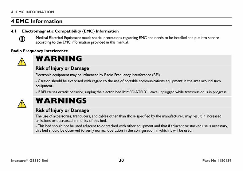
Medical Electrical Equipment needs special precautions regarding EMC and needs to be installed and put into service according to the EMC information provided in this manual.
WARNINGRisk of Injury or DamageElectronic equipment may be influenced by Radio Frequency Interference (RFI).
- Caution should be exercised with regard to the use of portable communications equipment in the area around such equipment.
- If RFI causes erratic behavior, unplug the electric bed IMMEDIATELY. Leave unplugged while transmission is in progress.
WARNINGSRisk of Injury or DamageThe use of accessories, tranducers, and cables other than those specified by the manufacturer, may result in increased emissions or decreased immunity of this bed.- This bed should not be used adjacent to or stacked with other equipment and that if adjacent or stacked use is necessary, this bed should be observed to verify normal operation in the configuration in which it will be used.
Invacare® G5510 Bed 30 Part No 1180159

4 EMC INFORMATION
Recommended separation distances between portable and mobile RF communications equipment and the G 5510 Bed
The G 5510 Bed is intended for use in an electromagnetic environment in which radiated RF disturbances are controlled. The customer or the user of the G 5510 Bed can help prevent electromagnetic interference by maintaining a minimum distance between portable and mobile RF communications equipment (transmitters) and the G 5510 Bed as recommended below, according to the maximum output power of the communications equipment.
Rated maximum output power of transmitter
W
Separation distance according to frequency of transmitterm
150 kHz to 80 MHz
d=1.2
80 MHz to 800 MHz
d=1.2
800 MHz to 2,5 GHz
d=2.3
0.01 .12 .12 .23
0.1 .38 .38 .73
1 1.2 1.2 2.3
10 3.8 3.8 7.3
100 12 12 23
For transmitters rated at a maximum output power not listed above, the recommended separation distance d in metres (m) can be estimated using the equation applicable to the frequency of the transmitter, where P is the maximum output power rating of the transmitter in watts (W) according to the transmitter manufacturer. NOTE 1 At 80 MHz and 800 MHz, the separation distance for the higher frequency range applies. NOTE 2 These guidelines may not apply in all situations. Electromagnetic propagation is affected by absorption and reflection from structures, objects and people.
P P P
Part No 1180159 31 Invacare® G5510 Bed

5 OPERATION
5 Operation
Refer to Operating the Bed on page 35
Refer to Using the Emergency Crank on page 39
Bed End
Bed EndHead Section
Foot Section
Locking Caster
Bed Frame
Slat
Bed Operation and Component Overview
Invacare® G5510 Bed 32 Part No 1180159

5 OPERATION
WARNINGRisk of Injury or DamageTo avoid unintentionally pressing the pendent buttons and causing injury or damage.
- DO NOT place pendent under or between objects.
WARNINGRisk of Injury or DamageTo avoid serious injury or product damage due to tripping hazards, strangulation hazards, and/or entangled, pinched, or severed cords:
- Ensure that all cords are routed and secured properly.
WARNINGRisk of Injury or DamageTo avoid pinching, crush and collapse hazards from bed deck contact with objects under the bed:
- DO NOT place any objects or let any individual underneath the bed or in between the raised bed frame components at anytime.
Part No 1180159 33 Invacare® G5510 Bed

5 OPERATION
5.1 Operation Verification
CAUTIONRisk of DamageTo avoid damage from misuse:
- Bed operation is intended for a duty cycle not to exceed max 10%, max 2 min./18 min.
- Allow a slight pause between adjustments and avoid pressing multiple buttons at the same time. If pendent buttons are depressed too rapidly or multiple buttons are pressed at the same time, the desired feature may not activate. Simply release the pendent button, permit a slight pause and then activate the next operation.
- If a button on the pendent does not release or sticks, the bed section will not stop moving. If this occurs or any other malfunction, unplug the bed from the electrical wall outlet.
Before placing any bed into use, test it by operating it through all phases of its operation.If any problems arise during the test, recheck all electrical connections and mechanical hook ups.This bed uses a six function pendent for all bed operations.
This bed is equipped with an emergency crank to allow operation in the event of a power outage.
Keep power supply as close to the electrical outlet as possible.
Invacare® G5510 Bed 34 Part No 1180159

5 OPERATION5.2 Operating the Bed
Raising and Lowering the Entire Bed • To raise the entire bed, press the "Bed Up" button.
• To lower the entire bed, press the "Bed Down" button.
Raising and Lowering the Head and Foot Sections• To raise the head of the bed, press the "Head Up" button; To lower the head of the bed, press the "Head Down" button.
• To raise the foot of the bed, press the "Foot Up" button; To lower the foot of the bed, press the "Foot Down" button.
FIGURE 1 Operating the Bed
For this procedure, refer to FIGURE 1 on page 35.To disable operation of the electric bed, lift connector cap and unplug the pendent cable from the bus cable port.To cut power to the bed, remove the power cord plug from the electrical outlet.
Bed Down Button
Bed Up Button
Head Down Button
Head Up Button
Foot Down Button
Foot Up Button
Head Section
Foot Section
Part No 1180159 35 Invacare® G5510 Bed

5 OPERATION5.3 Operating the Locking Function on the Locking Caster
• LOCK - Push down on the lever.
• UNLOCK - Pull up on the lever.
FIGURE 2 Operating the Locking Function on the Locking Caster
5.4 Electrical Connections
FIGURE 3 Electrical Connections
Locking the casters may not prevent the bed from moving on slick or slippery surfaces.
When installing/removing pendent cable, port cover, or power supply to bus cable, ensure that flat edge of each connector is aligned with the flat edge of the corresponding connector.
Unlocked Position
Locked Position
Locking Caster
Flat Edge
Pendent Connector
Pendent/Port Cover Connection
Pendent Connector
Port Cover Flat Edge of Pendent Connector
Flat Edge of Port Cover
Invacare® G5510 Bed 36 Part No 1180159

5 OPERATION5.5 Installing/Removing Pendent and/or Port Cover
Installing Pendent
1. Plug pendent cable into bus cable port located on either right or left side (Detail “A”).
2. Lower connector cap to lock the connection in place (Detail “C”).
Removing Pendent
1. To disable operation of the electric bed, lift the connector cap (Detail “B”).
2. Unplug the pendent cable from the bus cable port (Detail “A”).
Installing Port CoverThere is a port on each side of the bed for the pendent to be plugged in to that allows the pendent to be located on either side of the bed. The port that is not being used MUST be covered using the provided port cover.
1. In the unused port of the bus cable, install port cover (Detail “D).
2. Lower connector cap to lock the connection in place (Detail “F).
Removing Port Cover1. To remove the port cover, lift the port cover cap (Detail “E) and remove the port cover from the bus cable port.
For this procedure, refer to FIGURE 4 on page 38.
Ensure connection between pendent cable and bus cable port is tight, otherwise, connector cap will not lock in place (Detail “B”).
To disable the operation of electric beds, these models have pendents that can be removed and stored in a secure place.
Ensure connection between the bus cable and port cover is tight, otherwise, connector cap will not lock in place (Detail “E”).
Part No 1180159 37 Invacare® G5510 Bed

5 OPERATION
FIGURE 4 Installing/Removing Pendent and/or Port Cover
Bus Cable Port
Pendent Cable
Connection MUST be tight
PENDENT
Connector Cap
Connector Cap
Pendent Cable
Bus Cable Port
Detail “A”
Detail “B” Detail “C”
Pendent Cable and Bus Cable
Port
Pendent Cable Cap
PORT COVER
Unused Port
Bus Cable
Unused Port
Port Cover
Connector CapDetail “D”
Detail “E” Detail “F”
Connection MUST be tight
Connector Cap Connector Cap
Bus Cable PortPort Cover
Invacare® G5510 Bed 38 Part No 1180159

5 OPERATION5.6 Using the Emergency Crank
1. Disconnect the pendent from the bus cable.
2. Remove the emergency crank.
3. Locate the exposed shaft end according to the function you want to perform. Refer to FIGURE 5.
4. Attach the emergency crank to one of the following:
• Shaft of head actuator to raise/lower head section
• Shaft of Gearbox to raise/lower head section
• Shaft of foot actuator to raise/lower foot section.
5. Push in the emergency crank while turning it the desired direction. Turn clockwise to raise. Turn counterclockwise to lower.
-
FIGURE 5 Using the Emergency Crank
If the bed needs to be adjusted manually due to a power outage or an electronic malfunction, use the emergency crank to make the adjustments.You should find the emergency crank attached to the slats. If you do not find the crank, contact your dealer.
To Raise/Lower the Entire Bed
Shaft of Head Actuator to Raise/Lower the
Head Section
To Raise/Lower the Foot Section
Foot End
Emergency Crank
Part No 1180159 39 Invacare® G5510 Bed

5 OPERATION5.7 Optional Bed Rails
WARNINGRisk of Injury or DamageProper patient assessment and monitoring, and proper maintenance and use of equipment is required to reduce the risk of entrapment. Variations in bed rail dimensions, and mattress thickness, size or density could increase the risk of entrapment.
- Visit the FDA website at http://www.fda.gov to learn about the risks of entrapment. Review “A Guide to Bed Safety”, published by the Hospital Bed Safety Workgroup, located at www.invacare.com. Use the link located under each bed rail product entry to access this bed’s safety guide.
Invacare® G5510 Bed 40 Part No 1180159

6 DEALER SECTION - PACKAGING, HANDLING, AND SET-UP
6 Dealer Section - Packaging, Handling, and Set-Up
6.1 Unpacking and Handling
Unpacking the Bed Ends
1. Remove any loose packing from the carton.
2. Bed End carton includes:
• Two Bed Ends - Any surface of the bed ends may be gripped for handling except the gear box.
• Four Locking Casters
• One Drive Shaft Assembly in two pieces.
FIGURE 1 Unpacking the Bed Ends
WARNINGRisk of Injury or DamageThe procedures in this section MUST be performed by a qualified technician.Any modifications to the G5510 bed are strictly prohibited.
CAUTIONRisk of Injury or DamageTo avoid injury or damage from electrical shock or misuse:
DO NOT plug the power cord into a power source until assembly is complete. To do so could result in damage or personal injury.
DO NOT attempt to operate bed controls prior to completion of assembly, otherwise damage to bed components may occur. Carton
Drive ShaftCasters Packaging
Bed Ends
Part No 1180159 41 Invacare® G5510 Bed

6 DEALER SECTION - PACKAGING, HANDLING, AND SET-UP
Unpacking Foot and Head Sections1. Remove any loose packing from the carton.
2. Foot Section carton includes: One Foot End Section (electric beds include pendent, power supply with power cord, and head, foot and hi/lo motors with cables), and one emergency crank handle. Only frame members should be gripped on the foot section for handling.
3. Head Section carton includes: One Head End Section. Any part of the head section may be gripped for handling.
FIGURE 2 Unpacking Foot and Head Sections
Shipping Carton
Inserts
Head End Section
Insert
Insert
Insert
Power Supply
Foot End Section
Shipping Carton
Pendent Cable
Insert
Invacare® G5510 Bed 42 Part No 1180159

6 DEALER SECTION - PACKAGING, HANDLING, AND SET-UP6.2 Set-Up
Assembling the Head and Foot Sections
1. Remove the head section (G50) and foot section (G54) of the bed from their packing cartons.
2. Place the head section on its side to your left so the center mounting latches are on the right.
3. Open the head section to a 45° to 90° angle for support.
4. Place foot section on its side to your right with the head section pull tube at the top of the assembly. The center mounting rivets should be on the left.
For this procedure, refer to Assembling the Head and Foot Sections on page 44.
WARNINGDO NOT attempt to operate bed controls prior to completion of assembly as damage to bed components or personal injury may occur.
CAUTIONDO NOT use the slats as a hand hold to assemble/disassemble or move the bed, otherwise the slats may bend resulting in permanent damage.
Part No 1180159 43 Invacare® G5510 Bed

6 DEALER SECTION - PACKAGING, HANDLING, AND SET-UP
FIGURE 3 Assembling the Head and Foot Sections
5. Place the head and foot sections approximately 90° from each other.
6. Hook the bottom head section center mounting latch to the bottom foot section center mounting rivet (FIGURE 4).
7. Hook the top head section center mounting latch to the top foot section center mounting rivet (FIGURE 4).
For set-up purposes, the motors on the foot section as well as the crank handles should be on your right.
It may be necessary to lift the head section or foot section slightly to secure the mounting latches and rivets.
Foot Section
Head Section Pull TubeHead Section
45°-90°
Center Mounting LatchCenter
Mounting Rivet
Invacare® G5510 Bed 44 Part No 1180159
6 DEALER SECTION - PACKAGING, HANDLING, AND SET-UP
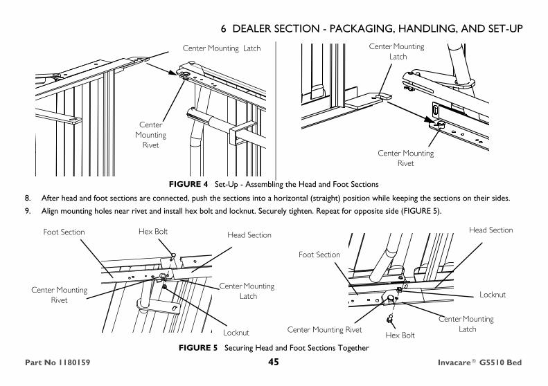
FIGURE 4 Set-Up - Assembling the Head and Foot Sections
8. After head and foot sections are connected, push the sections into a horizontal (straight) position while keeping the sections on their sides.
9. Align mounting holes near rivet and install hex bolt and locknut. Securely tighten. Repeat for opposite side (FIGURE 5).
FIGURE 5 Securing Head and Foot Sections Together
Center Mounting Latch
Center Mounting
Rivet
Center Mounting Latch
Center Mounting Rivet
Center Mounting LatchCenter Mounting Rivet
Hex Bolt
Locknut
Foot Section
Head Section
Center Mounting Rivet
Hex Bolt
Locknut
Foot Section Head Section
Center Mounting Latch
Part No 1180159 45 Invacare® G5510 Bed

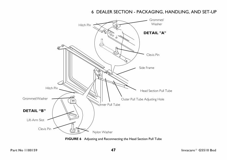
6 DEALER SECTION - PACKAGING, HANDLING, AND SET-UPAdjusting and Reconnecting the Head Section Pull Tube
1. To disconnect the head pull tube assembly from the side frame of the foot sections, remove the hitch pin, grommet/washer from the clevis pin (Detail "A").
2. Extend the inner pull tube shaft manually until the sections button "clicks" into the adjustment hole of the outer pull tube.
3. Connect the pull tube end assembly to the lift arm of the head section as follows (Detail "B"):
A. Insert the clevis pin into the lift arm slot.
B. Replace the grommet/washer.
C. Secure with hitch pin.
For this procedure, refer to FIGURE 6 on page 47.
Invacare® G5510 Bed 46 Part No 1180159
6 DEALER SECTION - PACKAGING, HANDLING, AND SET-UP
FIGURE 6 Adjusting and Reconnecting the Head Section Pull Tube
Hitch Pin
Lift-Arm Slot
Clevis Pin
Inner Pull Tube
Outer Pull Tube Adjusting Hole
Side Frame
Clevis Pin
Nylon Washer
Head Section Pull Tube
Grommet/Washer
DETAIL “B”
DETAIL "A"
Hitch Pin
Grommet/Washer
Part No 1180159 47 Invacare® G5510 Bed

6 DEALER SECTION - PACKAGING, HANDLING, AND SET-UP6.3 Assembling the Bed EndsInstalling the Casters
1. Lay the bed end flat on the floor.
2. Insert the shaft of a locking caster assembly into the caster socket in the leg of one of the bed ends.
3. To prevent excess movement of the bed during assembly, lock the caster. Refer to Operating the Locking Function on the Locking Caster on page 36
4. Repeat STEPS 1-3 for the remaining casters.
FIGURE 7 Assembling the Bed Ends
Installing/Removing the Bed Ends
Installing
1. Stand one bed end as close to the head section as possible (Detail “A”).
2. Grasp the head section, by the side, and raise it until the rivets on the corner plates of the section are high enough to place into the corner locks on the bed end (Detail “A”).
WARNINGRisk of Injury or DamageEnsure that all four casters are locked and that the bed does not move before transferring.
- DO NOT transfer occupant to the bed if bed is not stable.
For this procedure, refer to FIGURE 7 on page 48.
Locking Caster
Caster Socket
Bed End
Floor
Shaft
For this procedure, refer to FIGURE 8 on page 49.
Invacare® G5510 Bed 48 Part No 1180159

6 DEALER SECTION - PACKAGING, HANDLING, AND SET-UP
3. Tilt the bed end toward the head section and place the rivets into the corner locks (Detail “A”).
4. Return the bed end to its full upright position. The head section rivets will lock into place (Detail “A”).
5. Repeat the same procedure for other bed end (Detail “B”).
Removing
1. While holding the bed end at the foot of the bed, lift up on the foot section and disengage the rivets out of the corner locks (Detail “B”).
2. Place the bed end and foot section on the ground.
3. While holding the bed end at the head of the bed, lift up on the head section and disengage the rivets out of the corner locks (Detail “A”).
FIGURE 8 Installing/Removing the Bed Ends
WARNINGRisk of Injury or DamageTo avoid injury or damage from crush hazard:
DO NOT place your hand between the section and the bed end while assembling the bed ends.
Bed End
Rivets
Corner Locks
Head Section
Corner Locks
Rivets
Bed End
Foot Section
DETAIL “A” DETAIL “B”
Part No 1180159 49 Invacare® G5510 Bed

6 DEALER SECTION - PACKAGING, HANDLING, AND SET-UPAssembling the Drive Shaft
1. Remove the plastic caps from each end of the drive shaft.
2. Press spring button on the inner shaft and insert the inner shaft into the outer shaft.
3. Engage the spring button into the third positioning hole.
4. Attach the inner shaft to the bottom gear box output shaft on the head end of the bed.
5. Push in on the spring loaded end of the drive shaft and attach to the foot end of the bed as follows:
• Attach drive shaft to the Hi/Lo motor output shaft facing head end of bed.
WARNINGRisk of Injury or DamageDO NOT attempt to operate bed controls prior to completion of assembly as damage to bed components or personal injury may occur.
Close the gearbox shaft covers over all gearbox shafts not in use, before placing the bed in service. Otherwise damage or injury may occur.
For this procedure, refer to FIGURE 9 on page 51 and FIGURE 10 on page 52.
The drive shaft for the Hi/Lo function consists of two sections that are shipped unassembled. The inner shaft has a positioning spring button, and the outer shaft has three positioning holes, one storage position hole and a telescoping end.
A common gear box is used on both bed ends. The bottom output shaft is used at the head end and the top output shaft is used at the foot end of the bed.
Invacare® G5510 Bed 50 Part No 1180159

6 DEALER SECTION - PACKAGING, HANDLING, AND SET-UP
FIGURE 9 Assembling the Drive Shaft
• Attach the Hi/Lo Motor to the foot end gear box as follows:
i. Locate the Hi/Lo motor output shaft spring-loaded coupler.
ii. Ensure the Hi/Lo motor output shaft spring-loaded coupler is properly aligned with the foot end gear box as shown in Detail “A” of FIGURE 10 on page 52.
iii. Release the Hi/Lo motor output shaft spring-loaded coupler by pushing in against the Hi/Lo motor output shaft spring-loaded coupler and turning clockwise.
iv. The coupling will release and engage the foot end top gear box output shaft cross pins.
v. Ensure that all components are securely installed.
If necessary, shift bed end to right or left to align the Hi/Lo motor output shaft spring-loaded coupler with the foot end gear box.
Positioning HolesSpring loaded End
Storage First Second Third
Plastic Cap
Spring ButtonInner Shaft
Head End Gear Box
Drive Shaft
Head EndFoot End
Foot End Gear Box
Plastic Cap
Part No 1180159 51 Invacare® G5510 Bed

6 DEALER SECTION - PACKAGING, HANDLING, AND SET-UP
FIGURE 10 Assembling the Drive Shaft
��������
������
DETAIL “A”
Hi/Lo Motor Output Shaft Spring-Loaded Coupler
Top Gear Box Output Drive Shaft
Bed End
Drive Shaft
Hi/Lo Motor Output Shaft
Hi/Lo Motor Output Shaft
LOCKED POSITION
Hi/Lo Motor Output Shaft Spring-Loaded Coupler
Hi/Lo MotorOutput Shaft Spring-LoadedCoupler Shaft
OUTPUT SIDETop Gear Box
Output Drive Shaft
Bottom Gear Box Output Drive Shaft (Covered)
Gear Box
INPUT SIDE
Drive Shaft Cover
Input Drive Shaft (Covered)Hi/Lo Motor
UNLOCKED POSITION
Gear Box
Drive Shaft Cover
Drive Shaft
Invacare® G5510 Bed 52 Part No 1180159

6 DEALER SECTION - PACKAGING, HANDLING, AND SET-UPInspecting the Bed
1. Inspect the power supply cord and motor cables for cuts or damage to the cord and/or plug.
2. Inspect the power supply for any damage to the connectors.
3. Ensure that all cable plugs are connected securely.
4. Make sure all cables are routed properly.
5. If damage is found, contact an Invacare Customer Service Representative to report the damaged items and request appropriate replacement parts or products
6. Make all the electrical connections. Refer to Electrical Connections on page 36.
6.4 Electrical Connections
WARNINGRisk of Injury or DamageWhen installing any connectors into the bus cable, be sure the connector locking cap is secure after installation - otherwise, injury or damage may occur.
All motors, power supply, connectors and wiring are located on the foot section.
Connect power supply and pendent. Each connector is labeled with its specific function.
When installing/removing pendent cable, port cover, or power supply to bus cable, ensure that flat edge of each connector is aligned with the flat edge of the corresponding connector.
Part No 1180159 53 Invacare® G5510 Bed

6 DEALER SECTION - PACKAGING, HANDLING, AND SET-UP
FIGURE 11 Electrical Connections
6.5 Installing/Removing Mattress Keepers.
Installing1. Position mattress keeper over end slat as shown in Detail “B”.
2. Slide mattress keeper back until tab locks onto side rail as shown in Detail “C”.
Removing1. Grasp mattress keeper and lift tab up to release from side rail (Detail “B”).
2. Slide mattress keeper off of end slat (Detail “B”).
Recommended location for mattress keepers in on the end slat on both sides.
Flat Edge
Pendent Connector
Pendent/Port Cover Connection
Pendent Connector
Port Cover
Flat Edge of Pendent ConnectorFlat Edge of Port Cover
Invacare® G5510 Bed 54 Part No 1180159

6 DEALER SECTION - PACKAGING, HANDLING, AND SET-UP
FIGURE 12 Installing/Removing Mattress Keepers.
6.6 Connect Power Supply1. Plug power supply into bus cable port marked power.
Detail “A” - Location
Mattress Keeper
Mattress Keeper
Mattress KeeperEnd Slat
Detail “B” Detail “C”
Mattress Keeper
End Slat
Mattress Keeper
Tab End Slat
Bus CablePower Supply
Part No 1180159 55 Invacare® G5510 Bed

6 DEALER SECTION - PACKAGING, HANDLING, AND SET-UPFIGURE 13 Connect Power Supply
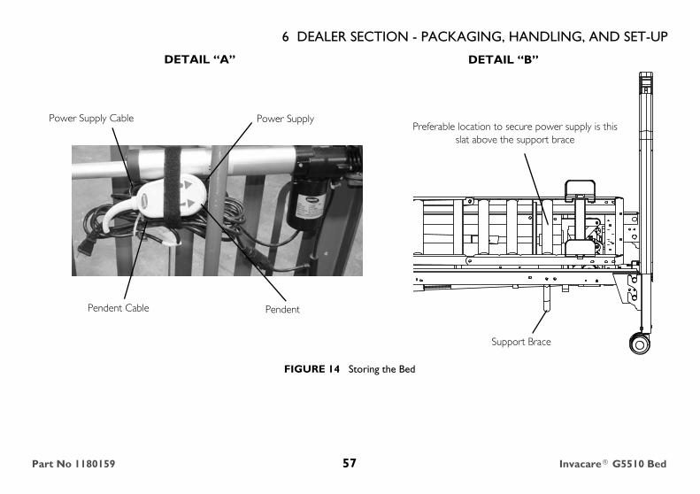
6.7 Storing the Bed
1. Coil up pendent cable and power supply cable and secure with hook and loop provided to the underside of the slat located above the support brace bed.
For this procedure, refer to FIGURE 14 on page 57.
It is not necessary to disconnect power supply and pendent from the bus cable for storage.
If bed is not being assembled immediately, retain the cartons and packaging for storage until ready for assembly.
Store the Invacare homecare bed in a dry area.
WARNINGRisk of Injury or DamageTo avoid injury or damage from falling objects and/sor moving parts:
DO NOT place other objects on top of the cartons.DO NOT leave pendent or power supply in the stored position (strapped to the bed) during operation.
CAUTIONRisk of DamageTo avoid damage during transport:
Power supply and pendent are intended to be stored onto slat located under support brace for protection during transportation
When performing STEP 1, the preferable slat to secure the pendent/power supply for storage is directly above the support brace. See Detail “B” in FIGURE 14.
Invacare® G5510 Bed 56 Part No 1180159
6 DEALER SECTION - PACKAGING, HANDLING, AND SET-UP
FIGURE 14 Storing the Bed
DETAIL “A” DETAIL “B”
PendentPendent Cable
Power SupplyPower Supply CablePreferable location to secure power supply is this
slat above the support brace
Support Brace
Part No 1180159 57 Invacare® G5510 Bed

7 TROUBLESHOOTING/MAINTENANCE - USER/DEALER
7 Troubleshooting/Maintenance - User/Dealer
7.1 Troubleshooting Electrical
SYMPTOM PROBABLE CAUSE USER SOLUTIONS DEALER SOLUTIONS
• Electric functions do not move. • End of stroke reached. • Operate opposite button. • Operate opposite button.
• Bed not plugged in. • Ensure power cord is plugged into power source.
• Ensure power cord is plugged into power source.
• Ensure motor and power supply are plugged into bus cable.
• Pendent not functioning. • Ensure Pendent cable not entangled/pinched.
• Ensure Pendent cable not entangled/pinched.
• Ensure pendent is correctly connected to power supply. Refer to Electrical Connections on page 54
• Cables • Ensure cables are not entangled/pinched.
• Call the dealer for repair/replacement of cables and/or motors.
• Ensure motor cable(s) and power supply are correctly connected. Refer to Assembling the Drive Shaft on page 50.
• Ensure cables are not entangled/pinched.
• Call Invacare for instructions to repair/replacement of cables and/or motors.
• Household fuse or breaker blown.
• Check household fuse/breaker box.
N/A
Invacare® G5510 Bed 58 Part No 1180159

7 TROUBLESHOOTING/MAINTENANCE - USER/DEALER
• Bed section does not move. • Broken connector cap. Call Dealer • Call Invacare for instructions to replace connector cap.
• Motors are not functioning. • Call dealer. • Check to make sure nothing is blocking actuator.
• Hi/Lo Motor not functioning.
• Ensure cables are not entangled or pinched.
• Call dealer.
• Ensure cables are not entangled or pinched.
• Ensure Drive shaft is correctly installed.
• Ensure Hi/Lo motor cable is correctly connected. Refer to Assembling the Drive Shaft on page 50.
• Thermal Protection Activated.
• Allow bed unit to sit for up to 30 minutes and retry.
• Allow bed unit to sit for 30 minutes and retry.
• Bed section does not stop moving.
• Pendent • Check for depressed/stuck buttons. If button is stuck, call dealer for repair. Unplug power cord from the wall.
• Replace pendent. Refer to Electrical Connections on page 54.
• Bed Hi/Lo movement does not stop.
• Defective Pendent• Damaged Cables
• Check cables, if damaged call dealer.
• Check cables, if damaged, replace. Refer to Assembling the Drive Shaft on page 50.
SYMPTOM PROBABLE CAUSE USER SOLUTIONS DEALER SOLUTIONS
Part No 1180159 59 Invacare® G5510 Bed

7 TROUBLESHOOTING/MAINTENANCE - USER/DEALER
7.2 Troubleshooting Mechanical
• Bed is producing unusual sounds, burning odors, or movement deviations observed in the controls, motors, or the limits switch functions.
• Electrical Component Error • Unplug power cord from the wall. Call Dealer.
• Call Invacare for instructions.
• Intermittent motor operation • Pushing button too quickly • Allow a slight pause between adjustments and avoid pressing multiple buttons at the same time. If pendent buttons are depressed too rapidly or multiple buttons are pressed at the same time, the desired feature may not activate. Simply release the pendent button, permit a slight pause and then activate the next operation.
• Call Invacare for instructions.
SYMPTOM PROBABLE CAUSE USER SOLUTIONS DEALER SOLUTIONS
• Bed does not stay in place. • Casters unlocked. • Lock Casters. • Lock Casters.
• Locking Caster not installed properly.
• Call Dealer • Ensure locking casters are installed properly. Refer to Assembling the Bed Ends on page 48.
SYMPTOM PROBABLE CAUSE USER SOLUTIONS DEALER SOLUTIONS
Invacare® G5510 Bed 60 Part No 1180159

7 TROUBLESHOOTING/MAINTENANCE - USER/DEALER
• Bed sections do not move. • Pull tube. • Check pull tube(s) for binding. Call dealer for repairs.
• Ensure pull tubes are properly connected. Refer to Adjusting and Reconnecting the Head Section Pull Tube on page 46.
• Bed ends move in opposite directions.
• Drive Shaft connected to wrong gear box shaft.
• Call dealer. • Reinstall drive shaft. Refer to Assembling the Drive Shaft on page 50.
• Hi/Lo function does not work. • Drive shaft disconnected. • Call dealer. • Reinstall Drive shaft. Refer to Assembling the Drive Shaft on page 50.
• Pressing function on pendent results in motion other than that intended.
• Motor cable connections are incorrect.
• Call dealer. • Verify Connections. Refer to Inspecting the Bed on page 53.
For access to part numbers, see online parts book at www.invacare.com or call Invacare.
SYMPTOM PROBABLE CAUSE USER SOLUTIONS DEALER SOLUTIONS
Part No 1180159 61 Invacare® G5510 Bed

8 MAINTENANCE AND CLEANING
8 Maintenance and Cleaning
Invacare recommends the following maintenance/cleaning procedures be conducted initially, between users or as needed. This form is provided as a guide to help with documentation8.1 Maintenance Checklist
WARNINGRisk of Injury or DamageTo avoid injury or damage from misuse:
- Read all general guidelines, warnings and cautions before performing any repair/maintenance on the bed.
- All repair and maintenance on the bed should be performed by a qualified technician.
Mechanical Inspection and Maintenance Electrical Inspection and Maintenance
❑ Inspect rail latches. Ensure that all rails engage and lock as specified. ❑ Inspect for damaged or loose wiring. Have a qualified technician replace any frayed or damaged cords.
❑ Lubricate rail pivot points and all mechanical hinge points, bushings, and surface contact points as needed with white lithium grease.
❑ Inspect all electrical bed components for damage or excessive wear (i.e. cracked or broken housings, or worn components).
❑ Inspect bed, rails, assist rails, or assist bars for the presence of tubing end caps and replace as required.
❑ Check pendent, power and motor cords for chafing, cuts or excessive wear.
❑ Inspect all bed components (i.e. rails, clevis pins, hitch pins, etc...) for damage or excessive wear and replaced as necessary
❑ Make sure all plugs are fully attached and free of damage.
❑ Visually examine all welds for cracks. ❑ Make sure all connectors are properly positioned and locked
❑ Inspect the head and foot sections for bending, warping or damage. ❑ Check all functions: Head raises and lowers properly, Foot raises and lowers properly, Bed Ends raise and lower properly.
Invacare® G5510 Bed 62 Part No 1180159

8 MAINTENANCE AND CLEANING
Pass/Fail❑ PASS: Bed and all components have passed all of the above inspection criteria and the bed is ready for placement into a client’s home.❑ FAIL: Bed, or any component, has failed any of the above inspection criteria. Tag the bed or component with a complete description of the
failure(s) and have the bed serviced.
8.2 Cleaning the Beds
Mechanical Inspection and Maintenance Electrical Inspection and Maintenance
❑ Inspect all bolts and rivets to ensure that they are securely tightened and functioning properly.
❑ Check sleep surfaces to ensure all slats are intact.
❑ Check casters to ensure they lock, if applicable, and roll properly.
WARNINGRisk of Injury or DamageTo avoid injury or damage from liquid ingress during maintenance:
- DO NOT spray water into any power supply connection ports.
- The electronic motors, power supply and pendents are protected against the entrance of dust and water when properly attached.
- Before disassembling or washing an electric bed, disconnect the power supply from the electrical outlet.
Part No 1180159 63 Invacare® G5510 Bed

8 MAINTENANCE AND CLEANINGWashing the Bed
1. Before cleaning the bed, perform the following:
• Ensure that the pendent cable, port cover, motor, actuators, and power supply are securely connected to the bus cable.
• Ensure connector cap on all connections is lowered to lock connection in place.
2. Disconnect the power supply of the bed from the electrical outlet before washing.
3. Make sure all electrical parts are not damaged and that all connection ports are plugged.
4. Remove the head and foot boards. Refer to Installing/Removing the Bed Ends on page 48.
5. Inspect bed components for any exposed metal. To prevent rusting, Invacare recommends covering those areas with touch-up paint.
6. Disinfect and wash all components and exterior surfaces using a mild soap/detergent and soft bristle brush or sponge. DO NOT submerge the bed frame or electrical parts.
Connector Cap
Connection MUST be tight
Invacare® G5510 Bed 64 Part No 1180159

8 MAINTENANCE AND CLEANING
Drying the Bed
7. Using household water pressure only, rinse thoroughly with water (maximum temperature 110° F or 43° C). DO NOT power wash or steam clean. DO NOT use solvents, bleach, alcohol, petroleum products, caustic agents, or highly alkaline or acidic agents to clean the bed.
CAUTIONRisk of DamageDirty water may damage or stain flooring. Grease leaks can lead to a fall or fire.
- Ensure bed ends are completely drained and dry before placing on flooring.
- Inspect bed ends for leaking grease. Contact service provider if grease or other residue is detected.
1. Tip the bed from side to side to allow any collected or trapped water to drain.
2. Thoroughly towel dry bed and all components.3. Repeat drying process until all components are dry
Ensure that the bed is completely dry before storing.
Part No 1180159 65 Invacare® G5510 Bed

Usability SurveyPlease complete the survey below to evaluate this manual. Your participation in the evaluation assists in the development of effective and usable manuals for our customers. The survey is also available online: http://www.invacare.com/TechnicalDocumentSurvey.
1. Please indicate your primary involvement with the product (Choose one):
____________________________________________________________2. Please indicate which product manual you are evaluating:
____________________________________________________________3. Evaluate the content:
Explain:________________________________________________________________________________________________________________________
4. Evaluate the Warnings/Cautions:
Explain:________________________________________________________________________________________________________________________
5. Evaluate the style:
Explain:________________________________________________________________________________________________________________________
6. Evaluate the illustrations:
Explain:________________________________________________________________________________________________________________________
7. Do you have suggestions for other ways of making this document easier to use?
Explain:____________________________________________________________
Thank you for completing this survey. If you have any questions or we may be of assistance to you, please feel free to contact us. Send your survey to:Invacare Technical Writing DepartmentInvacare CorporationOne Invacare WayElyria, OH [email protected], FAX 440-329-6975
� Product User/Owner � Product Service Technician� User Assistant � Health Care Provider� Product Dealer � Other (Please specify):
YES NOAfter reading this document, do you have a better understanding of how to use the product?
� �
Do you have a better understanding of any limitations on the use of this product?
� �
Is there any irrelevant information? � �Is the Table of Contents useful? � �Does any information seem inaccurate/misleading? � �Do you understand that misuse of the product can cause injury or damage?
� �
YES NOAre there any warnings/cautions that you do not understand? � �Are there too many warnings/cautions? � �Are there warnings/cautions that you feel do not apply to this product? � �
YES NOIs anything hard to locate/follow? � �Are any headings missing/confusing? � �Are there too many headings? � �Should any material be a bulleted list or checklist instead of numbered steps or a paragraph?
� �
Is there material that might be clarified by a visual? � �
YES NOAre the illustrations useful? � �Do the illustrations need more or less detail? � �Is the number/size of illustrations adequate? � �
Yes � No �
66

NOTES
67

Invacare Corporation
Making Life’s Experiences Possible™ USAOne Invacare WayElyria, Ohio USA44036-2125800-333-6900
Canada570 Matheson Blvd E Unit 8Mississauga OntarioL4Z 4G4 Canada800-668-5324
www.invacare.com
Part No 1180159 Rev A - 11/15/13