Embed Size (px)
Citation preview
N.V. SKY CLIMBER EUROPE S.A. Nijverheidsstraat 23 2570 Duffel BELGIUM / EUROPE Tel : +32-(0)3-887.81.20 Fax : +32-(0)3-887.09.94 E-mail: [email protected] http://www.skyclimber.com
TO EMPLOYER : It is imperative that this manual be given to the operator of SKY CLIMBER equipment and that he
reads, fully understands and follows all instructions contained herein.
WARNING : Any use of this equipment other than in strict accordance with these instructions shall be at the operator’s risk and may result in serious injury to him and others
REMEMBER SAFETY IS THE RESPONSIBILITY OF BOTH YOU A ND THE OPERATOR !
User Manual

Sky Climber Europe User Manual V 2.0
20 April 1999 - Page 2 -
TABLE OF CONTENTS Page FOREWORD 4 Section 1 - SAFETY : 6 1.0 Introduction ............................................................................................................. 6 1.1 Operator.................................................................................................................. 6 1.2 Safety equipment ................................................................................................... 6 1.3 General .................................................................................................................. 7 1.4 System support ...................................................................................................... 7 1.5 Steel wire rope ....................................................................................................... 7 1.6 Power Circuit ......................................................................................................... 8 1.6.1 General ........................................................................................................ 8
1.6.2 Electric Powered Hoist................................................................................... 8 1.6.3 Air Powered Hoist .......................................................................................... 9
1.7 Controls .................................................................................................................. 9 1.8 Operator’s Support / Work Platform ....................................................................... 9 1.9 Environmental Hazards .......................................................................................... 9 1.10 Hazardous Activities : Welding ............................................................................ 10 1.11 Corrosive Atmosphere.......................................................................................... 11
1.12 Safety Labels / Instructions................................................................................... 11 Section 2 - INTRODUCTION / DESCRIPTION : 12 2.0 Introduction.............................................................................................................. 12 2.1 General Features ................................................................................................... 12 2.2 Electric/Air Powered Hoists .................................................................................... 13 2.2.1 Technical Specifications ................................................................................ 13 2.2.2 Controls ......................................................................................................... 13 2.2.3 Crank Handle ................................................................................................. 14 2.2.4 Hoist Brake..................................................................................................... 14
2.3 Sky Lock Overspeed Sensitive Fall Arrest Device.................................................... 15 2.4 Overload & Underload Device .................................................................................. 15
Section 3 - OPERATION / INSTALLATION & REEVING : 16 3.0 General ................................................................................................................... 16 3.1 Sky Lock Overspeed Brake..................................................................................... 16 3.1.1 Installation ..................................................................................................... 16 3.1.2 Operation ....................................................................................................... 17 3.2 Emergency operation - Power Failure .................................................................... 17 3.2.1 Ascent - Optional Hand Crank ....................................................................... 18 3.2.2 Descent - Controlled Lowering Lever ............................................................ 18 3.3 Electric Powered Hoist ........................................................................................... 18 3.3.1 General........................................................................................................... 18 3.3.2 Power Supply ................................................................................................. 19 3.3.3 Low Voltage Operation .................................................................................. 19 3.3.4 Power Cords................................................................................................... 19 3.3.5 Thermal Overload .......................................................................................... 19 3.4 Hoist operation ...................................................................................................... 19 3.5 Hoist Installation and Reeving ................................................................................ 20

Sky Climber Europe User Manual V 2.0
20 April 1999 - Page 3 -
TABLE OF CONTENTS (Continued) Section 4 - STEEL WIRE ROPE : 22 4.0 Wire Rope .............................................................................................................. 22 4.1 Specifications and preparation................................................................................ 22 4.1.1 Specifications ................................................................................................ 22 4.1.2 Preparation .................................................................................................... 22 4.2 Handling / Use / Storage ........................................................................................ 23 4.2.1 General .......................................................................................................... 23 4.3 Inspection / Replacement Criteria .......................................................................... 24 4.4 Fittings .................................................................................................................... 25 4.5 Sky Climber Wire-Winder ....................................................................................... 26 Section 5 - INSPECTION AND MAINTENANCE : 27 5.0 General Information .............................................................................................. 27 5.1 Types of Inspection : ............................................................................................... 27 5.1.1 Factory Inspection ......................................................................................... 27 5.1.2 Field Inspection ............................................................................................. 27 5.2 Frequency of Inspections ....................................................................................... 27 5.3 Operators Safety Equipment Inspection ................................................................ 29
5.4 Sky Lock Overspeed Brake Inspection / Functional checks .................................. 30 5.4.1 Work environment.......................................................................................... 30 5.4.1.1 Group 1 - Normal ....................................................................................... 30 5.4.1.2 Group 2 - Contaminated............................................................................. 30 5.4.1.3 Group 3 - Freezing ..................................................................................... 30 5.4.2 Inspecting the Sky Lock Overspeed Brake .................................................... 31 5.4.2.1 Inspecting Trip Performance of Mounted Sky Lock .................................... 31 5.4.2.2 Inspecting Load Supporting Performance................................................... 31
5.5 Over- Underload Calibration and Inspection............................................................ 33. 5.6 Hoist Components Inspection and Maintenance ...................................................... 33
Section 6 - TROUBLESHOOTING 35 Section 7 - PLATFORM TRANSFER INSTRUCTIONS 37 Section 8 - SAFETY CHECKLISTS 38 8.1 Daily Checklist Form ............................................................................................... 38 8.2 Set-up Checklist Form............................................................................................. 39

Sky Climber Europe User Manual V 2.0
20 April 1999 - Page 4 -
TO THE EXPERIENCED SKY CLIMBER OPERATOR : The typical first reaction of the experienced operator to an instruction manual is “Why should I read it? I’ve had enough experience with Sky Climber hoists to write the Manual !” You may be right, but before you put this Manual aside, please hear us out. The new European Safety Standard EN1808 prescribes the supply of a manual with the equipment. In addition, this manual is intended to remind experienced operators of the safe operating practices they should consistently follow. Are you operating the system according to the book, or have short cuts and omissions crept in ? Have we omitted anything important ? Do you disagree with us on anything in this Manual ? If so, please let us know by any possible means. Our address, fax and e-mail address is on the front cover. We welcome your comments ! TO THE NEW SKY CLIMBER OPERATOR : Welcome to the ever growing group of Sky Climber hoist operators ! We know the Sky Climber hoist can be operated safely. Properly operated and maintained, it will continue to operate for many years to come. This manual will guide you through the features of the Sky Climber hoist, and will help you to start operating it a safe way. Throughout this Manual the words WARNING, CAUTION and NOTE appear in bold face font.

Sky Climber Europe User Manual V 2.0
20 April 1999 - Page 5 -
“WARNING” is preceded by the safety alert symbol and, with its corresponding message, is underlined. This indicates that injury to personnel could occur if the proper procedures are not followed during operation or maintenance. Always read and fully understand and act according to the WARNING extremely carefully. “CAUTION” indicates a possible hazard to the product or its components if the proper procedures are not followed. Whenever the word CAUTION appears, special attention should be given to prevent possible equipment damage. “NOTE” is used to stress a point or to give additional information concerning the procedures being discussed. These WARNINGS and CAUTIONS are not all inclusive. It is impossible for Sky Climber Europe, to know, evaluate and advise on every conceivable way in which our products may be used or serviced, and of all possible resulting hazardous consequences. It is therefore extremely important for anyone who uses a procedure about which this manual is silent to first satisfy himself that it will not jeopardise his own safety, the safety of others, or cause product or component damage. Every effort has been taken to make this Manual as complete and accurate as possible at the time of publication. Sky Climber Europe, however, reserves the right to continually improve its products. For this reason, changes may have been made to the Sky Climber hoist or its accessories which are not detailed in this Manual.
WARNING : Failure to inspect, maintain and operation of Hoist, Sky Lock, and accessories as described in this manual, could result in serious injury or death.

Sky Climber Europe User Manual V 2.0
20 April 1999 - Page 6 -
SECTION 1 SAFETY
P R E V E N T A C C I D E N T S !
Read and follow this safety check list. It includes all safety requirements of State and National codes as well as the recommendations of Sky Climber Europe. Follow all applicable Federal, State and Local codes and regulations pertaining to safety; they are minimum standards for the safe operation of Sky Climber equipment. 1.0 INTRODUCTION Sky Climber Hoists and accessories are designed and manufactured to the highest standards in the industry for your safety. ACCIDENTS WILL BE AVOIDED IF YOU FOLLOW THE INSTRUCTIONS IN THIS MANUAL. It is the operator’s responsibility to be sure that he and his co-workers are fully familiar with this Manual before using the Sky Climber hoist and related equipment. Once the equipment leaves Sky Climber’s control, the operator is responsible for its safe use, operation and maintenance. 1.1 OPERATOR 1.1.1 People who operate suspended equipment must be :
• Emotionally and physically able to withstand the stress of working at elevations • Able to read and understand this Manual and follow its instructions.
1.1.2 If an operator is subject to seizures or loss of physical control, he shall not work at elevations 1.1.3 Operators must be safety conscious, responsible, and not under the influence of alcohol, drugs
or other substances. 1.2 SAFETY EQUIPMENT 1.2.1 All persons using suspended access equipment must at all times wear safety harnesses
attached by lanyards and rope grabs to independently hung lifelines. Do not disconnect/remove safety belts, harnesses or lanyards until you are safely on the ground or until completely disembarked from suspended devices to a safe location.
1.2.2 Use a short lanyard, and maintain the rope grabs high on the lifeline as practical. 1.3 GENERAL 1.3.1 Know and understand the operation of this equipment. Be sure that all persons who service,
erect, dismantle or use this equipment are thoroughly familiar with, and follow all the safety rules in this Manual. Make certain that they also comply with all Federal, State and Local codes and regulations that apply to this equipment and its safe use.
1.3.2 Training in the use of Sky Climber equipment is available. Contact Sky Climber for details. 1.3.3 Safety Helmets shall be worn at all times when servicing, erecting, disassembling, or using this
equipment. 1.3.4 Provide protection for operators from collision with overhead obstacles and falling objects. 1.3.5 Provide protection below the suspended equipment to prevent injury to personnel from falling
objects. 1.3.6 Keep all persons from beneath suspended equipment. 1.3.7 Never work alone on a suspended platform or where aid is not immediately available in case of
an emergency. Maintain contact with your supervisor at all times. 1.3.8 Do not overload the hoist. The working load limit (W.L.L.) of the hoist is always listed on the
data plate. This rating includes wire rope, power cord, platform, men tools and other associated equipment.
Sky Climber Europe User Manual V 2.0
20 April 1999 - Page 7 -
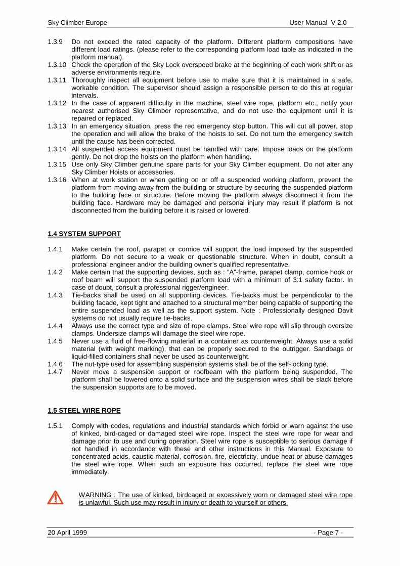
1.3.9 Do not exceed the rated capacity of the platform. Different platform compositions have different load ratings. (please refer to the corresponding platform load table as indicated in the platform manual).
1.3.10 Check the operation of the Sky Lock overspeed brake at the beginning of each work shift or as adverse environments require.
1.3.11 Thoroughly inspect all equipment before use to make sure that it is maintained in a safe, workable condition. The supervisor should assign a responsible person to do this at regular intervals.
1.3.12 In the case of apparent difficulty in the machine, steel wire rope, platform etc., notify your nearest authorised Sky Climber representative, and do not use the equipment until it is repaired or replaced.
1.3.13 In an emergency situation, press the red emergency stop button. This will cut all power, stop the operation and will allow the brake of the hoists to set. Do not turn the emergency switch until the cause has been corrected.
1.3.14 All suspended access equipment must be handled with care. Impose loads on the platform gently. Do not drop the hoists on the platform when handling.
1.3.15 Use only Sky Climber genuine spare parts for your Sky Climber equipment. Do not alter any Sky Climber Hoists or accessories.
1.3.16 When at work station or when getting on or off a suspended working platform, prevent the platform from moving away from the building or structure by securing the suspended platform to the building face or structure. Before moving the platform always disconnect it from the building face. Hardware may be damaged and personal injury may result if platform is not disconnected from the building before it is raised or lowered.
1.4 SYSTEM SUPPORT 1.4.1 Make certain the roof, parapet or cornice will support the load imposed by the suspended
platform. Do not secure to a weak or questionable structure. When in doubt, consult a professional engineer and/or the building owner’s qualified representative.
1.4.2 Make certain that the supporting devices, such as : “A”-frame, parapet clamp, cornice hook or roof beam will support the suspended platform load with a minimum of 3:1 safety factor. In case of doubt, consult a professional rigger/engineer.
1.4.3 Tie-backs shall be used on all supporting devices. Tie-backs must be perpendicular to the building facade, kept tight and attached to a structural member being capable of supporting the entire suspended load as well as the support system. Note : Professionally designed Davit systems do not usually require tie-backs.
1.4.4 Always use the correct type and size of rope clamps. Steel wire rope will slip through oversize clamps. Undersize clamps will damage the steel wire rope.
1.4.5 Never use a fluid of free-flowing material in a container as counterweight. Always use a solid material (with weight marking), that can be properly secured to the outrigger. Sandbags or liquid-filled containers shall never be used as counterweight.
1.4.6 The nut-type used for assembling suspension systems shall be of the self-locking type. 1.4.7 Never move a suspension support or roofbeam with the platform being suspended. The
platform shall be lowered onto a solid surface and the suspension wires shall be slack before the suspension supports are to be moved.
1.5 STEEL WIRE ROPE 1.5.1 Comply with codes, regulations and industrial standards which forbid or warn against the use
of kinked, bird-caged or damaged steel wire rope. Inspect the steel wire rope for wear and damage prior to use and during operation. Steel wire rope is susceptible to serious damage if not handled in accordance with these and other instructions in this Manual. Exposure to concentrated acids, caustic material, corrosion, fire, electricity, undue heat or abuse damages the steel wire rope. When such an exposure has occurred, replace the steel wire rope immediately.
WARNING : The use of kinked, birdcaged or excessively worn or damaged steel wire rope is unlawful. Such use may result in injury or death to yourself or others.

Sky Climber Europe User Manual V 2.0
20 April 1999 - Page 8 -
1.5.2 Use Sky Climber specified steel wire rope, clamps, thimbles and other work associated components. See section 4 for more information.
1.5.3 Rig from top of structure allowing approximately 3 meter of extra steel wire rope at the bottom to reeve hoist. Sky Climber strongly recommends that all rope drops be of sufficient length to reach a safe surface level when reeved.
WARNING : If it is necessary to rig with less steel wire rope than specified above, it is mandatory that the bitter end of the steel wire rope be looped back on itself and secured with a “J”-clamp. See figure 4.4.
1.5.4 Steel wire rope must be rigged to remain vertical, with suspension points directly above the
hoist entry guide or lead-in device at all times. 1.5.5 A double wire suspension (primary and secondary safety steel wire rope) system has to be
used at all times in order to comply with European safety regulations. Make certain that each steel wire rope is attached to its own suspension point on the suspension device.
1.5.6 Special precautions must be taken to protect the steel wire rope when welding. See section 1.10 for list of precautions.
1.5.7 Steel wire rope fittings (J-clamps, shackles and Talurit clamps) must be checked for tightness at first loading and then at the beginning of each shift.
1.6 POWER CIRCUIT 1.6.1 General 1.6.1.1. Do not remove the motor from the hoist unless the platform is safely supported. 1.6.1.2. Optional manual crank handle can be used to raise the suspended equipment if power fails
and in order to get the load back on the primary steel wire rope in case of a power failure. This will enable you to reset the tripped Sky Lock. Refer to section 2.2.3 on how to use the crank handle. If Sky Lock has tripped due to overspeed do NOT crank the hoist up in order to try re-setting the sky lock.
1.6.1.3. Emergency brake release may be used for controlled lowering of the suspended equipment in case of power failure. See section 3.2.2.
1.6.1.4. Do not allow the electrical power supply cable / air hose to become tangled with any obstruction or the suspension ropes when raising or lowering the suspended equipment.
Make certain the electrical cord is of sufficient length to allow full travel of the suspended equipment. 1.6.2 Electric Powered Hoists 1.6.2.1 Before using electric powered hoists, have a qualified person check the voltage while hoisting
with your maximum allowable load. The voltage should vary with no more than 10 % of the nominal power supply voltage indicated on the electromotor data plate.
1.6.2.2 Make sure that the electrical power source is “earthed” to a point of sufficient low resistance. 1.6.2.3 Use only approved connector plugs and power supply cords with strain relief, correctly
assembled from hoist to power supply. Verify ground continuity, and use a ground fault interrupter (as required by code in your location). Consult local safety authorities for further information.
1.6.2.4 Ensure that all metal parts, outlets, junction boxes and other components that might come in contact with live conductors are properly earthed.
1.6.2.5 Always use a power cable cord with earth conductor when using electrically driven handtools on a suspended platform. Verify that the handtools are properly earthed. (or use handtools of the double insulated type)
Sky Climber Europe User Manual V 2.0
20 April 1999 - Page 9 -
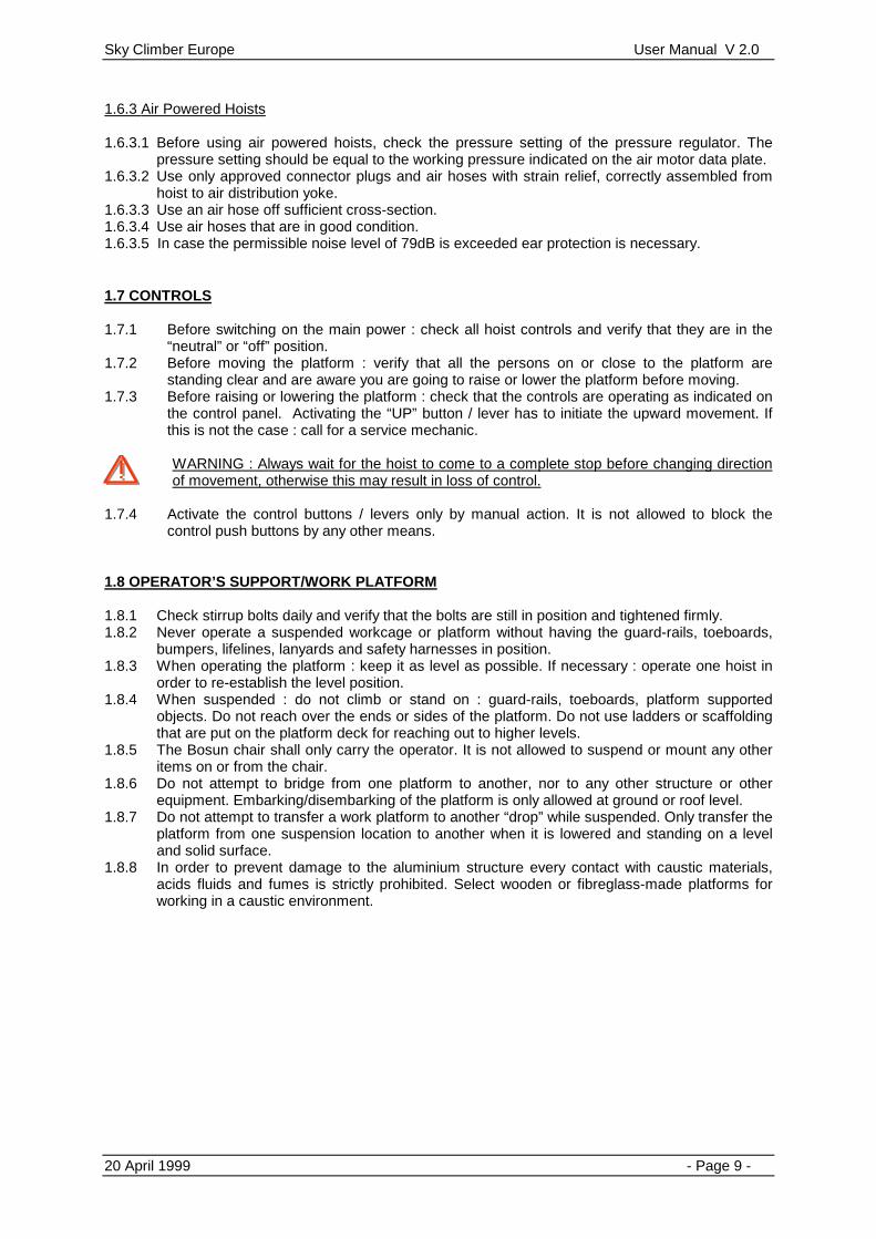
1.6.3 Air Powered Hoists 1.6.3.1 Before using air powered hoists, check the pressure setting of the pressure regulator. The
pressure setting should be equal to the working pressure indicated on the air motor data plate. 1.6.3.2 Use only approved connector plugs and air hoses with strain relief, correctly assembled from
hoist to air distribution yoke. 1.6.3.3 Use an air hose off sufficient cross-section. 1.6.3.4 Use air hoses that are in good condition. 1.6.3.5 In case the permissible noise level of 79dB is exceeded ear protection is necessary. 1.7 CONTROLS 1.7.1 Before switching on the main power : check all hoist controls and verify that they are in the
“neutral” or “off” position. 1.7.2 Before moving the platform : verify that all the persons on or close to the platform are
standing clear and are aware you are going to raise or lower the platform before moving. 1.7.3 Before raising or lowering the platform : check that the controls are operating as indicated on
the control panel. Activating the “UP” button / lever has to initiate the upward movement. If this is not the case : call for a service mechanic.
WARNING : Always wait for the hoist to come to a complete stop before changing direction of movement, otherwise this may result in loss of control.
1.7.4 Activate the control buttons / levers only by manual action. It is not allowed to block the
control push buttons by any other means. 1.8 OPERATOR’S SUPPORT/WORK PLATFORM 1.8.1 Check stirrup bolts daily and verify that the bolts are still in position and tightened firmly. 1.8.2 Never operate a suspended workcage or platform without having the guard-rails, toeboards,
bumpers, lifelines, lanyards and safety harnesses in position. 1.8.3 When operating the platform : keep it as level as possible. If necessary : operate one hoist in
order to re-establish the level position. 1.8.4 When suspended : do not climb or stand on : guard-rails, toeboards, platform supported
objects. Do not reach over the ends or sides of the platform. Do not use ladders or scaffolding that are put on the platform deck for reaching out to higher levels.
1.8.5 The Bosun chair shall only carry the operator. It is not allowed to suspend or mount any other items on or from the chair.
1.8.6 Do not attempt to bridge from one platform to another, nor to any other structure or other equipment. Embarking/disembarking of the platform is only allowed at ground or roof level.
1.8.7 Do not attempt to transfer a work platform to another “drop” while suspended. Only transfer the platform from one suspension location to another when it is lowered and standing on a level and solid surface.
1.8.8 In order to prevent damage to the aluminium structure every contact with caustic materials, acids fluids and fumes is strictly prohibited. Select wooden or fibreglass-made platforms for working in a caustic environment.

Sky Climber Europe User Manual V 2.0
20 April 1999 - Page 10 -
1.9 ENVIRONMENTAL HAZARDS
WARNING : Touching live powerlines may result in Death or serious injury.
1.9.1 Refer to federal, state and local codes and regulations when working in the vicinity of electrical
overhead powerlines. Consult the local power company for safe operating procedures before rigging.
1.9.2 Do use of long-handled tools when working close to electric powerlines. 1.9.3 The minimum separation between live power lines and the platform and all of its components
is 3 meter. 1.9.4 Verify that there are no obstructions in the vertical travel zone of the platform. Always keep a
good look-out when raising or lowering the platform. When running into an obstruction : immediately stop the platform and inspect the platform and obstruction for possible damage and/or hook-up. Proceed in a safe direction to clear the obstruction.
WARNING : Take care not to overload the system or get in a slack suspension wire situation when running into an obstacle.
1.9.5 For Temporary suspended platforms with a lifting height of over 40m and intended to be used
on locations exposed to wind speeds above 14 m/s (= 50 km/h) an adequate restraint shall be provided.
1.9.6 Carefully follow the instructions for using and checking the Sky Lock fall arrest device in a normal, contaminated or freezing environment.
1.9.7 When using a hoist in or near a Marine (or corrosive/salty) environment, more frequent inspections are required. In these applications a thorough 4-hours interval inspection of the hoists, steel wire rope, fittings and equipment has to be executed. Make sure to replace all the components that get degraded by corrosion or wear.
WARNING : The electric powered hoists are not rated for operating in an explosion hazardous environment. Select an air powered hoist.
1.10 HAZARDOUS ACTIVITIES : WELDING During welding, the electrocution hazard and the risk of the welding current passing through the suspension steel wire ropes shall be eliminated by taking the following precautions : 1.10.1 Use an insulated thimble to attach each steel wire rope to its suspension point. Electrically
insulate the extra steel wire rope stored on the roof to prevent grounding, or terminate the suspension rope at the insulated thimble.
1.10.2 Cover the steel wire rope support cable with insulating material above and below the hoist. (See Fig. 1.1) This can be done by using a length of rubber-hose, taped in position around the cable. Proceed as follows : a. Above the Sky Lock brake extending upwards for approximately 1.2 meter (more if required
by local safety regulations). b. Below the hoist, extending downward sufficiently far enough to insulate the tail line from the
platform. The portion of the tail line that hangs free below the platform must be guided and/or retained so that it does not become grounded.

Sky Climber Europe User Manual V 2.0
20 April 1999 - Page 11 -
Figure 1.1
1.10.3 Cover each Hoist, Sky Lock and wire winder with protective covers made out of insulating
material. 1.10.4 Connect a ground conductor from the platform to the work piece. The size of this conductor
shall be equal to, or greater than the size of the stinger lead. NOTE : This must be a secondary conductor and shall not be in series with the primary
conductor between the welder and the workpiece. 1.11 CORROSIVE ATMOSPHERE When Sky Climber hoists are being used in corrosive work-associated atmospheres such as acid washing, the hoist and its supporting steel wire rope shall be protected from direct contact with the corrosive solutions and agents. Each day, on the final descent, the steel wire rope shall be washed with a neutralising solution and relubricated. Stainless steel wire rope, which is far more resistant to corrosion deterioration can be obtained from Sky Climber. Daily examination of the full supporting length of wire rope is mandatory. 1.12 SAFETY LABELS / INSTRUCTIONS The Sky Climber equipment shall be labelled as follows :
COMPACT CX 500
Use only 8 mm SKY CLIMBER Steel wire ropewith a min. actual breaking load of 40 kN (or better)
Manufactured by :SKY CLIMBER EUROPE N.V.Boomsesteenweg 14B-2630 AartselaarBELGIUM
W.L.L. : 500 Kg MFG NR : MFG date : Speed : 8,8 m/min. Selfweight : 43 Kg

Sky Climber Europe User Manual V 2.0
20 April 1999 - Page 12 -
SECTION 2 INTRODUCTION / DESCRIPTION
2.0 INTRODUCTION This Manual contains Sky Climber’s minimum requirements for safety, operation and maintenance. Follow all federal, state and local codes and regulations pertaining to the safe use and maintenance of this equipment.
WARNING : Failure to inspect, maintain and operation of hoist, Sky Lock, and accessories as described in this manual, could result in serious injury or death.
2.1 GENERAL FEATURES Sky Climber hoists are is rated for manlifting, of the traction sheave type, and portable hoist. The hoist is certified by CE, Underwriters Laboratory (UL) and the Canadian Standards Association. They climb up- and down on a 8 or 9mm steel wire rope and carries men and materials to their workstations. Sky Climber hoists are used to lift suspended platforms, workcages, Bosun chairs and other approved devices in suspended access operations. All hoists are available in 4 different models :
• Single Phase, 220-240V/50 Hz , 24V Control Voltage • Single Phase, 220-240V/60 Hz , 24V Control Voltage • Three Phase, 380-415V/50 Hz , 24V Control Voltage • Three Phase, 380-415V/60 Hz , 24V Control Voltage • Air • Other models are available upon request
WARNING : A Sky Lock overspeed sensitive fall arrest device shall be used AT ALL TIMES with each type of hoist.
2.2 ELECTRIC / AIR POWERED HOIST The Sky Climber hoist consists out of :
• Traction sheave / Gearbox unit • Drive Motor Unit (electric / air)
⇒ with built-on Motor control unit • Brake Unit (electromagnetic or pneumatic, spring actuated)
⇒ built-in for Compact & CX ⇒ built-on for Alpha
• Central Control Unit (central control box (CE) or hoist-mounted control box (UL)) • Sky Lock Overspeed sensitive Fall arrest device

Sky Climber Europe User Manual V 2.0
20 April 1999 - Page 13 -
2.2.1 Technical specifications
Compact 400 Motor 50Hz / 1~ 60Hz / 1~ 50Hz / 3~ 60Hz / 3~ Air
Voltage / Press. 220-240V 220-240V 380-415V 380-415V 6 bar Current / Flow 3.6 A 5.4 A 2.4 A 1.8 A 1.7 m³/min
Power 0.55 kW 0.74 kW 0.55 kW 0.88 kW 1.25 kW Motor speed 1420 rpm 1700 rpm 1400 rpm 1690 rpm 1500 rpm
Weight 35 kg 36 kg 35 kg 36 kg 30 kg Capacity 400 kg 400 kg 400 kg 400 kg 400 kg
Steel Wire Rope 8mm 8mm 8mm 8mm 8mm Actual Breaking Load 44,63kN 44,63kN 44,63kN 44,63kN 44,63kN
Climbing Speed 8.5 m/min 10.6 m/min 8.4 m/min 10.6 m/min 8.5 m/min Sky Lock III (8mm) III (8mm) III (8mm) III (8mm) III (8mm)
CX 500 Motor 50Hz / 1~ 60Hz / 1~ 50Hz / 3~ 60Hz / 3~ Air
Voltage / Press. 220-240V 220-240V 380-415V 380-415V 6 bar Current / Flow 7 A 7.5 A 3.2 2.1 1.7 m³/min
Power 0.88 kW 1.1 kW 0.88 1.1 1.25 kW Motor speed 1420 rpm 1710 rpm 1400 1700 1500 rpm
Weight 41 kg 43 kg 41 kg 43 kg 30kg Capacity 500 kg 500 kg 500 kg 500 kg 500 kg
Steel Wire Rope 8mm 8mm 8mm 8mm 8mm Actual Breaking Load 44,63kN 44,63kN 44,63kN 44,63kN 44,63kN
Climbing Speed 8.5 m/min 9.7 m/min 8.5 m/min 9.7 m/min 8.5 m/min Sky Lock III (8mm) III (8mm) III (8mm) III (8mm) III (8mm)
Alpha 500 Motor 50Hz / 1~ 60Hz / 1~ 50Hz / 3~ 60Hz / 3~ Air
Voltage / Press. 220-240V 220-240V 380-415V 380-415V 6 bar Current / Flow 6.8 5.7 A 3.3 A 2.1 A 2 m³/min
Power 0.88 0.88 kW 0.88 kW 1.1 kW 0.96 kW Motor speed 1420 1700 rpm 1400 rpm 1700 2800 rpm
Weight 62 kg 63 kg 62 kg 63 kg 60 kg Capacity 500 kg 500 kg 500 kg 500 kg 500 kg
Steel Wire Rope 9mm 9mm 9mm 8mm 9mm Actual Breaking Load 66,1kN 66,1kN 66,1kN 66,1kN 66,1kN
Climbing Speed 8.5 m/min 9.7 m/min 8.5 m/min 9.7 m/min 8.5 m/min Sky Lock III (9mm) III (9mm) III (9mm) III (9mm) III (9mm)
Alpha 800 Motor 50Hz / 1~ 60Hz / 1~ 50Hz / 3~ 60Hz / 3~ Air
Voltage / Press. 220-240V 220-240V 380-415V 380-415V 6 bar Current / Flow 9.4 A 11 A 4.3 A 3.7 A 2 m³/min
Power 1.33 kW 1.5 kW 1.1 kW 1.5 kW 0.96 kW Motor speed 1370 rpm 1720 rpm 1410 rpm 1660 rpm 2800 rpm
Weight 65 kg 67 kg 66 kg 67 kg 65kg Capacity 800 kg 800 kg 800 kg 800 kg 800 kg
Steel Wire Rope 9mm 9mm 9mm 9mm 9mm Actual Breaking Load 66,1kN 66,1kN 66,1kN 66,1kN 66,1kN
Climbing Speed 8.5 m/min 9.7 m/min 8.5 m/min 9.7 m/min 8.5 m/min Sky Lock II (9mm) II (9mm) II (9mm) II (9mm) II (9mm)

Sky Climber Europe User Manual V 2.0
20 April 1999 - Page 14 -
2.2.2 Controls
Refer to the central controlbox manual for a detailed description of the central control unit. 2.2.2.1 UP and DOWN SWITCH/LEVER : 2.2.2.2 SELECTOR SWITCH : (only electric powered hoist) 2.2.2.3 EMERGENCY STOP Button : 2.2.2.4 CONTROLLED DESCENT LEVER : In the event of a power failure, the controlled descent lever, located on the end-side of the hoist can be
activated to manually release the hoist brake. This is done by pushing it towards the hoist-end. (See Figure 2.1 & 2.2). The hoist will lower at a controlled speed of +/- 8.5 m/min. The controlled descent lever shall only be activated when the power supply has been disconnected.
WARNING : Always disconnect power to the platform before activating the controlled descent lever, otherwise serious injury or death may result.
2.2.3 CRANK HANDLE : A crank handle is supplied with every hoist for raising the hoist and its load when there is a power
failure and upward travel of the Sky Climber hoist is required. Most of the time the distance over which the hoist is to be raised is very limited : the main goal is to get the load back on the primary suspension steel wire rope in order to un-load and re-set the Sky Lock.
How to use the crank handle : • Disconnect power supply plug (to central control box / air distribution yoke) • Remove the plastic safety plug in the centerhole of the drive motor or brake unit. • Insert the crank handle on the shear pin of the shaft rear-end. • Hold the crank handle firmly whit one hand while lifting the brake manually. • Rotate the handle in the counter-clockwise direction to climb. • When stopping, release the controlled lowering lever before releasing the crank.
Figure 2.1 Figure 2.2
2.2.4 HOIST BRAKE : The hoist brake is spring-loaded, with electro-magnetic or pneumatic release and manual override. To use manual override, pull Controlled Lowering Lever toward outer end of hoist. See Figure 2.1 & 2.2 NOTE: This brake may not be serviced in the field. NOTE: Never manually release the Hoist brake for normal lowering operations.

Sky Climber Europe User Manual V 2.0
20 April 1999 - Page 15 -
2.3 SKY LOCK OVERSPEED SENSITIVE FALL ARREST DEVICE The Sky Lock overspeed brake provides additional backup to the safety devices built into the Sky Climber hoist. The Sky Lock is a device which senses the dynamic speed of the wire rope as it passes through the Sky Lock mechanism. If, as the Sky Lock brake is travelling down the wire rope, the factory pre-set speed is exceeded, the Sky Lock brake will lock onto the wire rope and support the load. The secondary steel wire rope cannot be released until the load on the Sky Lock brake is relieved. The right type of Sky Lock (See Figure 2.3) should be used with the right type of hoist (see 2.2.1). These models provide a manual trip lever for manual activation or functional checking. Installation, operating procedures and functional checking procedures are defined in Section 5.4.2
Figure 2.3
2.4 OVERLOAD & UNDERLOAD DEVICE
The over-/underload device is a combined device which detects an overload or underload situation to avoid danger to persons and damage to machines. It is mounted for each hoist on the end stirrup or on the walk true stirrup. Refer to the “Safety Devices Assembly Manual” for more detailed drawings. The overload device prevents the hoist from moving upwards in an overload situation. The underload device prevents the hoist from moving downwards in an underload situation. In both situations an audio alarm will occur to warn the operators.

Sky Climber Europe User Manual V 2.0
20 April 1999 - Page 16 -
SECTION 3 OPERATION / INSTALLATION & REEVING
3.0 GENERAL Users are responsible for reading, understanding and following the instructions in this manual. Do not operate Sky Climber equipment until you have read and understood this manual, and are willing to follow its instructions. Consult your supervisor or nearest Sky Climber Office if you have any questions concerning these instructions, or if training is required. 3.1 SKY LOCK OVERSPEED BRAKE The Sky Lock overspeed brake is a safety device which senses the speed of the rope passing through its mechanism. If the factory pre-set actuation speed is exceeded as the Sky Lock is travelling down the wire rope, the Sky Lock brake will lock onto the wire rope and support the descending load. The wire rope cannot be released until the load on the Sky Lock brake is relieved. NOTE: Use always the right type of Sky Lock for the right type of Hoist. (See 2.2.1) 3.1.1 Installation The Sky Lock brake is installed above and attached to the Sky Climber hoist with a coupling link. The Sky Lock brake may also be attached to platforms as part of a secondary wire rope installation, or to other equipment which may require the use of a dynamic braking device. Consult Sky Climber Europe for use of the Sky Lock brake in other than Sky Climber hoist applications. Before passing the wire rope through the Sky Lock brake, the reset handle must be placed in the reset position. See Figure 3.1. After the wire rope has been passed through the Sky Lock brake, the operation of the brake must be inspected according to procedures in Section 5.4.2 of this manual.
Figure 3.1

Sky Climber Europe User Manual V 2.0
20 April 1999 - Page 17 -
3.1.2 Operation Should the SKY LOCK brake engage due to an overspeed condition, do not attempt to release or reset it. Instead, remove men from suspended equipment, and lower it to ground or raise it to roof by means other than the hoist. Then contact your nearest Sky Climber representative. SKY LOCK brakes may also be engaged by:
• Turning manual trip lever • Sudden movement of men on platform or repeated vibration
In the event the Sky Lock brake engages for reasons other than overspeed, check condition of equipment and wire rope below the Sky Lock brake. If satisfactory, operate hoist in up direction 5 to 10cm to relieve load on the Sky Lock brake, then turn reset handle as indicated on the Sky Lock brake decal, until the Sky Lock brake resets. (See Figure 3.2)
Figure 3.2
WARNING: Failure to inspect and functionally check Sky Lock brake operation at the beginning of each work shift in accordance with Section 5.4.2 could result in serious injury or death.
3.2 EMERGENCY OPERATION - POWER FAILURE In the event of loss of power, the hoist may be raised by using the option of hand crank, or lowered using the Controlled Lowering Lever.
WARNING: Always Disconnect power at the pigtail connection before using the manual crank or Controlled Lowering Lever, otherwise serious injury or death may result.

Sky Climber Europe User Manual V 2.0
20 April 1999 - Page 18 -
3.2.1 Ascent - Optional Hand Crank If power fails and you desire to raise suspended equipment:
• Disconnect power supply. • Remove protective cover and insert the hand crank • While tightly holding crank with one hand, pull Controlled Lowering Lever as far as it will go
with the other hand (thus brake), and begin cranking in a counter-clockwise direction.
WARNING: Release Controlled Lowering Lever to set Hoist brake before releasing crank, otherwise serious injury could result.
3.2.2 Descent - Controlled Lowering Lever If power fails and you desire to lower the hoist and its load:
• Disconnect power at the pigtail connector. • Release Hoist brake by gently pulling Controlled Lowering Lever as far as it will go. (See
Figure 3.3 & 3.4) CAUTION : Partial release of Hoist brake may result in overheating and premature brake wear.
WARNING: Before descending, be sure that optional hand crank is removed from hoist, otherwise, serious injury or death could result.
Figure 3.3 Figure 3.4

Sky Climber Europe User Manual V 2.0
20 April 1999 - Page 19 -
3.3 ELECTRIC POWERED HOIST 3.3.1 General For typical installation on a scaffold and for reeving instructions, see Section 3.5
WARNING: An electric powered Sky Climber hoist shall NOT be used in an explosive atmosphere.
An explosive atmosphere is one in which flammable gases or vapors or small particles are or may be present in the air in quantities sufficient to produce an explosive or ignitable mixture. 3.3.2 Power Supply Check technical specifications for minimum power requirements (see 2.2.1). CAUTION: The motor may overheat if the measured voltage at the motor during operation is less than 90% or more than 110% of the voltages shown on the motor data plate. On exceptionally long drops, locate the power source in the middle of the drop, thereby reducing the amount of power cord required. 3.3.3 Low Voltage Operation If a problem in motor performance exists when operating two hoists due to low voltage, the use of a booster transformer or of a separate power cord for each hoist is recommended. 3.3.4 Power Cords Because of varying platform load, source voltage and electrical system impedance, it is impossible to recommend optimum electric cord wire sizes, but Sky Climber recommended supply cable will be satisfactory in nearly all cases. Extremely long drops may necessitate the use of a voltage booster transformer or location of the power source in the middle of the drop, thereby reducing the required power cord length. IF A BOOSTER TRANSFORMER IS NEEDED, CALL YOUR SKY CLIMBER REPRESENTATIVE. The power cord must be secured to the swing stage by strain relief devices or other means to prevent the connector from pulling apart. When two power cords are used in series, include strain relief devices. Make sure the power cord length is sufficient to permit free travel of the platform without applying undue strain to the cord strain relief. It may be necessary to connect to building power midway between upper and lower travel limits to ensure full travel of the platform and to avoid limitation of travel due to insufficient power cord or voltage drop. When finished for the day, make certain the power cord is disconnected at the main outlets. Protect power cords from rain and water at all times. Make certain the ground connector of the building power receptacle is grounded. See Safety Check List, Section 2. Do not attempt to alter any connectors to fit power outlets. Do not use deteriorated or contaminated components.

Sky Climber Europe User Manual V 2.0
20 April 1999 - Page 20 -
3.3.5 Thermal Overload When the motor is overheated because of excessive current draw or prolonged use in hot weather, a thermal overload switch will cut power to the motor windings. Determine the cause of overheating and make necessary corrections. Allow the motor to cool approximately 20 minutes. During this time, the thermal overload switch will automatically reset. 3.4 HOIST OPERATION The electric hoist is activated by movement of the directional switch in the desired direction of travel. Travel may be stopped by releasing the directional switch, which cuts power to the motor and sets the hoist brake.
WARNING: Allow Hoist to come to a full stop before changing direction of travel. Rapidly changing position of directional switch may result in loss of control.
3.5 HOIST INSTALLATION AND REEVING These mounting and reeving instructions are directed to the reeving of a hoist mounted on the stirrup of a stage. These same instructions are generally applicable to the reeving of Compact CX 500 Hoist mounted on work cages, bosun chairs and other work platforms. Read and understand the paragraphs describing operation of the hoist before attempting reeving. Prior to reeving, test the Sky Lock in accordance with Pre-reeving Inspection, Section 5.4.2.1; and inspect the Hoist in accord with Section 5.6. Figure 3.5 illustrates a typical assembly with safety equipment.
Figure 3.5
STEP 1: Rigging
Install rigging as described in Section 7.0, or arrange for rigging to be installed by your local Sky Climber Office.
STEP 2:

Sky Climber Europe User Manual V 2.0
20 April 1999 - Page 21 -
Lay out swing stage and assemble stirrups. Be sure to install end rails if stirrups are located more than 45cm or more in from end of platform. Install guard-rails, toeboards and screening as required by governing safety codes. Tighten bolts. Figure 3.6 illustrates a typical assembly.
Figure 3.6
STEP 3: Lift the Hoist, insert stirrup strap into recess in stirrup, and retain by use of the lock nuts and Grade 5 retaining bolts provided. Tighten nuts securely. Test Sky Lock operation following pre-reeving inspection procedures in Section 5.4.2.1. Assemble the Sky Lock brake to the hoist entrance guide, making certain that the rectangular link is assembled to provide adequate clearance for the straight passage of the rope without interference. Set the Sky Lock brake by rotating the reset handle. STEP 4: Connect power STEP 5: With the Hoist and stirrup maintained in the vertical position, thread the prepared top (see Section 4.1.2) into the hoist entrance guide. Push rope into the unit until it stops. Then move directional switch/lever in UP direction, while maintaining downward pressure on wire rope, until self-reeving starts. Also insert the secondary rope into the Sky Lock.
WARNING: Keep hands clear of pinch pint where wire rope enters Sky Lock brake and Hoist entrance.
CAUTION: Be sure that exit guide is clear, and that the wire rope can run freely away from the Hoist. STEP 6: Test rigging by raising Hoist and platform or other suspended equipment about 0.5 meter off the ground. Have an assistant jump on suspended equipment while an experienced operator/rigger checks all rigging. Visually inspect all bolted connections of rigging and suspended equipment.
Test emergency lowering system by raising suspended equipment about 1 Meter off the ground, then manually releasing and re-engaging main Hoist brake using Controlled Lowering Lever. (see Section 3.2.2) Test Sky Lock trip performance as described in Section 5.4.2.2. Test Sky Lock load performance as described in Section 5.4.2.3.

Sky Climber Europe User Manual V 2.0
20 April 1999 - Page 22 -
SECTION 4 STEEL WIRE ROPE
4.0 WIRE ROPE
WARNING: Always wear gloves to protect hands when working with wire rope.
Steel wire rope used for hoisting personnel must be treated with extreme care. It must be properly maintained or its useful life will be shortened. Wire rope is an expendable item and begins to wear the moment it is put into use. A wire rope which is left in use beyond its useful life endangers personnel and property. Therefore, wire rope must be periodically inspected to be sure that it is in good condition. Ropes which show sign of wear or deterioration must be replaced immediately to avoid personal injury and property damage. Always use a wire rope of the correct diameter (8 or 9mm), construction and length. 4.1 SPECIFICATIONS and PREPARATION : 4.1.1 Specifications Use only wire rope obtained from Sky Climber. Use of other wire rope may impair the safety of personnel and Hoist performance.
WARNING: Use of wire rope obtained from sources other than Sky Climber could result in serious personal injury and/or property damage.
Steel wire rope for Compact and CX hoists: Part n°: 51008304 Conform to: ISO 2408, NBN 04-001 Rope diameter: 8mm Construction: 6x19S, steel core Type and direction of lay: Right hand, regular lay, preformed Surface finish of the wires: Galvanised Tensile strength: 1960N/mm2 Theoretical breaking load: 49,24kN Actual breaking load: 44,63kN Lubrication: Lightly greased Steel wire rope for Alpha Hoists: Part n°: 51008301 Conform to: ISO 2408, NBN 04-001 Rope diameter: 9mm Construction: 4x36WS, polypro core Type and direction of lay: Right hand, regular lay, preformed Surface finish of the wires: Galvanised Tensile strength 2160N/mm2 Theoretical breaking load: 78,5kN Actual breacking load: 66,1kN Lubrication: Lightly greased
4.1.2 Preparation

Sky Climber Europe User Manual V 2.0
20 April 1999 - Page 23 -
Prepare wire rope ends as shown in Figure 4.1, by brazing both ends to aid in reeving and to avoid unlaying.
Figure 4.1 4.2 HANDLING / USE / STORAGE 4.2.1 General Wire rope shall be stored in a coil as shown in Figure 4.2 or on a drum. Stored wire rope shall be protected from physical abuse, inclement weather and corrosive materials.
Figure 4.2
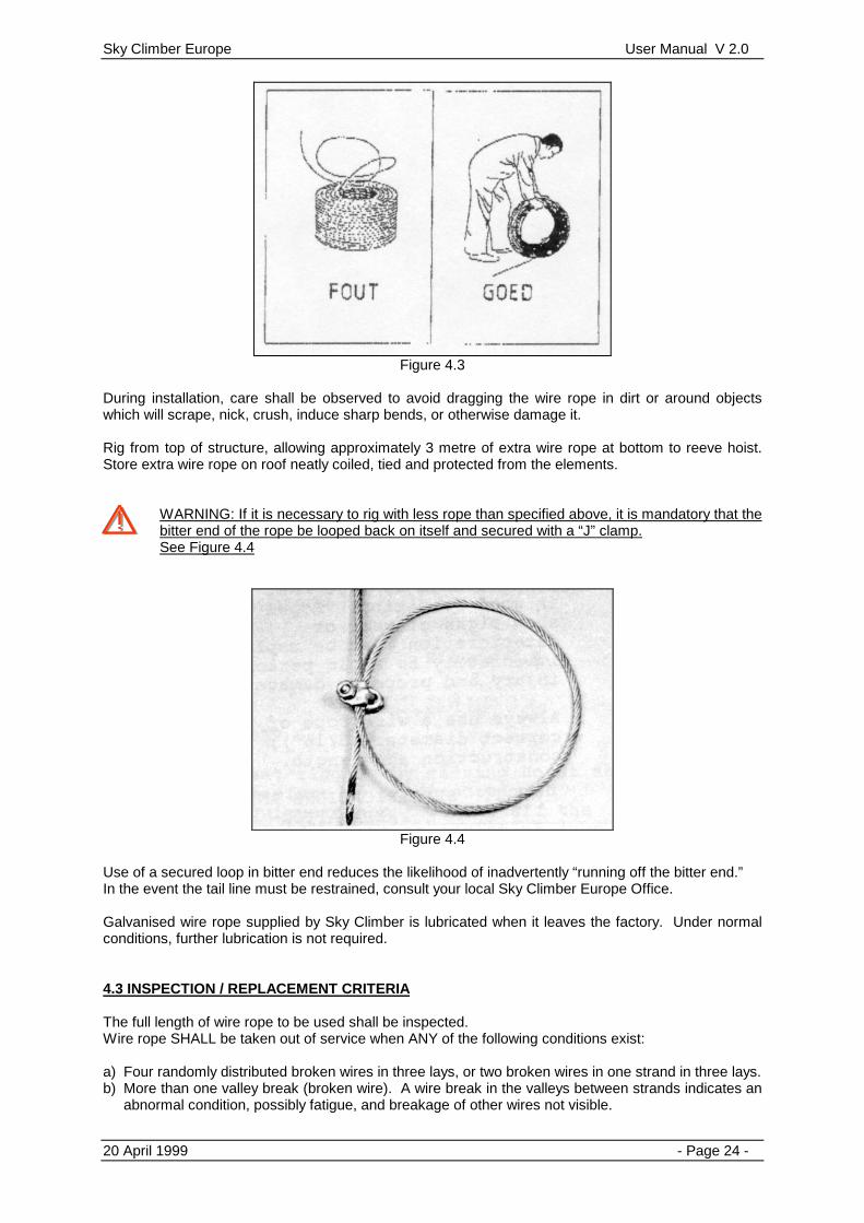
Do not drop wire rope from top of structure. Wire rope shall be lowered hand-over-hand. Unreeling or uncoiling of wire rope shall be done as shown in Figure 4.3 Use extreme care to avoid kinking or inducing a twist.
Sky Climber Europe User Manual V 2.0
20 April 1999 - Page 24 -
Figure 4.3
During installation, care shall be observed to avoid dragging the wire rope in dirt or around objects which will scrape, nick, crush, induce sharp bends, or otherwise damage it. Rig from top of structure, allowing approximately 3 metre of extra wire rope at bottom to reeve hoist. Store extra wire rope on roof neatly coiled, tied and protected from the elements.
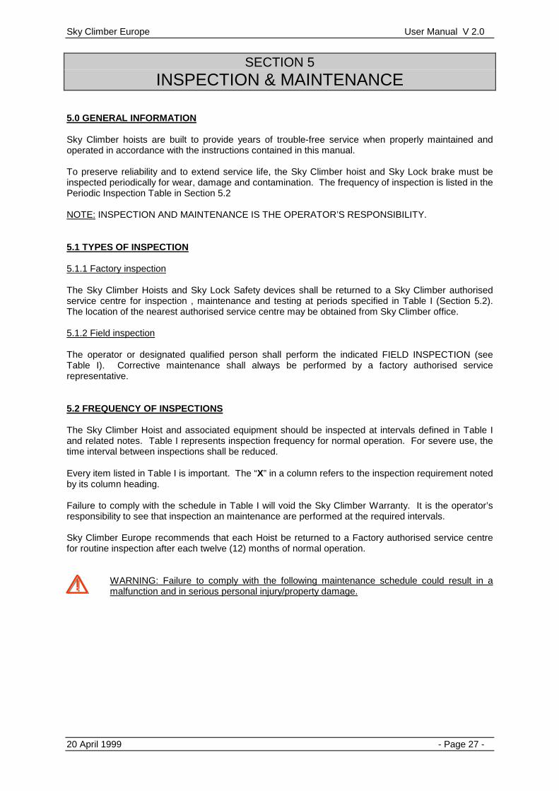
WARNING: If it is necessary to rig with less rope than specified above, it is mandatory that the bitter end of the rope be looped back on itself and secured with a “J” clamp. See Figure 4.4
Figure 4.4
Use of a secured loop in bitter end reduces the likelihood of inadvertently “running off the bitter end.” In the event the tail line must be restrained, consult your local Sky Climber Europe Office. Galvanised wire rope supplied by Sky Climber is lubricated when it leaves the factory. Under normal conditions, further lubrication is not required. 4.3 INSPECTION / REPLACEMENT CRITERIA The full length of wire rope to be used shall be inspected. Wire rope SHALL be taken out of service when ANY of the following conditions exist: a) Four randomly distributed broken wires in three lays, or two broken wires in one strand in three lays. b) More than one valley break (broken wire). A wire break in the valleys between strands indicates an
abnormal condition, possibly fatigue, and breakage of other wires not visible.

Sky Climber Europe User Manual V 2.0
20 April 1999 - Page 25 -
c) Kinking, crushing, bird-caging or any other damage resulting in distortion of the rope structure. d) Evidence of any heat damage from any cause. e) Evidence of rope deterioration from corrosion. f) Noticeable rusting, corrosion, pitting or more than two broken wires in the vicinity of end
attachments. g) Evidence of core failure (a lengthening of rope lay and a reduction in rope diameter suggests core
failure). h) 5% reduction of wire rope diameter (when measured under load).
WARNING: Replacement rope shall be to Sky Climber’s specifications.
Wire rope is measured across its largest dimensions on the outer limits of the strands. See Figure 4.5
Figure 4.5
NOTE: Consult your Wire Rope Manufacturers Manual or the “Wire Rope Users Manual” published by American Iron & Steel Institute for a comprehensive list and pictures or examples of critical inspection and replacement factors for wire rope.

Sky Climber Europe User Manual V 2.0
20 April 1999 - Page 26 -
4.4 FITTINGS Use only aluminium Talurit wire rope clamps or Deka wire rope clamps (see Figure 4.6) with a minimum of three clamps spaced approximately 8cm apart.
Figure 4.6
DO NOT USE “U” type clamps as illustrated in Figure 4.7. They cause crushing of wires and reduction in strength of the wire rope.
Figure 4.7
Always use a 9mm heavy duty thimble and a 5/8” screw pin shackle to avoid permanent damage and to retain full strength in the wire rope for use on future jobs. Insulated thimbles are available for rigging platforms which are to be used for welding. Braze both ends of wire rope. See Figure 4.1
WARNING: Always check rigging and wire rope clamps before each work shift.
4.5 SKY CLIMBER WIRE-WINDER The single or dual drum motorised Wire-Winder is available as an accessory item. The Wire-Winder is intended for special applications where the tail line cannot hang free. Secure the Wire-Winder on the platform end stirrup or walkthrough stirrup. Position to allow a smooth passage of the wire rope through the conduit to the departure guide of the hoist. Continually observe Wire-Winder during operation to assure that wire rope lays properly and does not kink. CAUTION : To alert operators they are nearing end of rope, the last 5m should be marked with bright red or yellow paint.
WARNING: Make certain that sufficient rope is used in Wire-Winder to avoid running off rope end.
Sky Climber Europe User Manual V 2.0
20 April 1999 - Page 27 -
SECTION 5 INSPECTION & MAINTENANCE
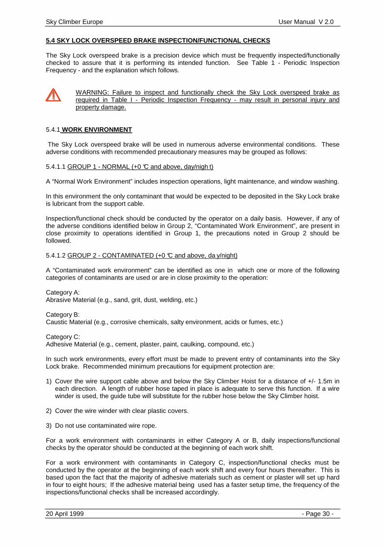
5.0 GENERAL INFORMATION Sky Climber hoists are built to provide years of trouble-free service when properly maintained and operated in accordance with the instructions contained in this manual. To preserve reliability and to extend service life, the Sky Climber hoist and Sky Lock brake must be inspected periodically for wear, damage and contamination. The frequency of inspection is listed in the Periodic Inspection Table in Section 5.2 NOTE: INSPECTION AND MAINTENANCE IS THE OPERATOR’S RESPONSIBILITY. 5.1 TYPES OF INSPECTION 5.1.1 Factory inspection The Sky Climber Hoists and Sky Lock Safety devices shall be returned to a Sky Climber authorised service centre for inspection , maintenance and testing at periods specified in Table I (Section 5.2). The location of the nearest authorised service centre may be obtained from Sky Climber office. 5.1.2 Field inspection The operator or designated qualified person shall perform the indicated FIELD INSPECTION (see Table I). Corrective maintenance shall always be performed by a factory authorised service representative. 5.2 FREQUENCY OF INSPECTIONS The Sky Climber Hoist and associated equipment should be inspected at intervals defined in Table I and related notes. Table I represents inspection frequency for normal operation. For severe use, the time interval between inspections shall be reduced. Every item listed in Table I is important. The “X” in a column refers to the inspection requirement noted by its column heading. Failure to comply with the schedule in Table I will void the Sky Climber Warranty. It is the operator’s responsibility to see that inspection an maintenance are performed at the required intervals. Sky Climber Europe recommends that each Hoist be returned to a Factory authorised service centre for routine inspection after each twelve (12) months of normal operation.
WARNING: Failure to comply with the following maintenance schedule could result in a malfunction and in serious personal injury/property damage.
Sky Climber Europe User Manual V 2.0
20 April 1999 - Page 28 -
ITEM
FIELD
FACTORY AUTHORISED SERVICE CENTRE
WHEN REEVED
EACH WORK SHIFT
Every 3 Months
Every 12 Months
SAFETY EQUIPMENT
x x
ROPE CONDITION
x x
OVER-/UNDERLOAD DEVICE
x x
SKY LOCK - Coupling nuts & Bolts
Note (2) x
Note (1) & (4) x
Note (3) Note (3)
HOIST UNIT - Coupling nuts & Bolts - Rope Housing Drain
x x x
x x
x
WORK PLATFORM
x x
RIGGING
x x
ELECTRICAL CONNECTIONS
x
x
Table 1 - Periodic inspection frequency
Table notes: 1. Frequency of inspection is dependent upon the “Work Environment”:
• Normal - check weekly • Abrasive or caustic - check daily • Freezing - check every two hours
2. Inspection method is different than Note 1. See instructions in Section 5. 3. Return to Factory authorised service Centre:
• every three months if used in contaminated or freezing environments • every six months if used in a normal environment
See instructions in Section 5. 4. Check every four hours when work environment includes adhesives.

Sky Climber Europe User Manual V 2.0
20 April 1999 - Page 29 -
5.3 OPERATORS SAFETY EQUIPMENT INSPECTION 5.3.1 Check that each person has a separate lifeline (Figure 5.1), and is adequately tied off to a
substantial building structure, but not to the same device used to support the Sky Climber hoist suspension rope.
Figure 5.1
Inspect the lifeline to insure that it has not been damaged and will meet governing safety codes, rules and regulations. Replace any rope which is worn or oil soaked.
5.3.2 Check performance of safety rope grab to insure that it will adequately support the operator’s
weight. Follow the rope grab manufacturer’s instructions completely. 5.3.3 Inspect lanyard, safety belt or harness attachment hardware to insure that all items are in good
condition and can be attached or removed without difficulty. Do not use webbed belts or lanyards with broken stitching. See Figure 5.2 for the type of operator safety equipment available from Sky Climber Europe.
Figure 5.2
5.3.4 Where attachment of the safety belt lanyard to a wire rope line mounted on the stage is
permitted by the governing safety authorities, check safety wire rope and means of attachment to stage to ensure that attachment fittings are secure and will develop adequate strength.
WARNING: Never go aloft without a lifeline and properly attached safety belt or harness.
Sky Climber Europe User Manual V 2.0
20 April 1999 - Page 30 -
5.4 SKY LOCK OVERSPEED BRAKE INSPECTION/FUNCTIONAL CHECKS The Sky Lock overspeed brake is a precision device which must be frequently inspected/functionally checked to assure that it is performing its intended function. See Table 1 - Periodic Inspection Frequency - and the explanation which follows.
WARNING: Failure to inspect and functionally check the Sky Lock overspeed brake as required in Table I - Periodic Inspection Frequency - may result in personal injury and property damage.
5.4.1 WORK ENVIRONMENT The Sky Lock overspeed brake will be used in numerous adverse environmental conditions. These adverse conditions with recommended precautionary measures may be grouped as follows: 5.4.1.1 GROUP 1 - NORMAL (+0 °C and above, day/nigh t) A “Normal Work Environment” includes inspection operations, light maintenance, and window washing. In this environment the only contaminant that would be expected to be deposited in the Sky Lock brake is lubricant from the support cable. Inspection/functional check should be conducted by the operator on a daily basis. However, if any of the adverse conditions identified below in Group 2, “Contaminated Work Environment”, are present in close proximity to operations identified in Group 1, the precautions noted in Group 2 should be followed. 5.4.1.2 GROUP 2 - CONTAMINATED (+0 °C and above, da y/night) A “Contaminated work environment” can be identified as one in which one or more of the following categories of contaminants are used or are in close proximity to the operation: Category A: Abrasive Material (e.g., sand, grit, dust, welding, etc.) Category B: Caustic Material (e.g., corrosive chemicals, salty environment, acids or fumes, etc.) Category C: Adhesive Material (e.g., cement, plaster, paint, caulking, compound, etc.) In such work environments, every effort must be made to prevent entry of contaminants into the Sky Lock brake. Recommended minimum precautions for equipment protection are: 1) Cover the wire support cable above and below the Sky Climber Hoist for a distance of +/- 1.5m in
each direction. A length of rubber hose taped in place is adequate to serve this function. If a wire winder is used, the guide tube will substitute for the rubber hose below the Sky Climber hoist.
2) Cover the wire winder with clear plastic covers. 3) Do not use contaminated wire rope. For a work environment with contaminants in either Category A or B, daily inspections/functional checks by the operator should be conducted at the beginning of each work shift. For a work environment with contaminants in Category C, inspection/functional checks must be conducted by the operator at the beginning of each work shift and every four hours thereafter. This is based upon the fact that the majority of adhesive materials such as cement or plaster will set up hard in four to eight hours; If the adhesive material being used has a faster setup time, the frequency of the inspections/functional checks shall be increased accordingly.

Sky Climber Europe User Manual V 2.0
20 April 1999 - Page 31 -
5.4.1.3 GROUP 3 - FREEZING (0° C and below day/nigh t) Temperature of 0° C and below without the presence of moisture do not adversely affect the Sky Lock brake. However, if the work environment of either Group 1 or 2 changes to include freezing temperature and sufficient moisture to form ice inside the Sky Lock brake, there is a possibility that the unit will fail to function as intended, with resultant potential danger to the user. Under these circumstances the operator must take reasonable precautions to prevent moisture from entering the Sky Lock brake. To ensure that the unit is functioning properly, it should be inspected/functionally checked at the beginning of each work shift and a minimum of every two hours thereafter during the course of the workday. Should the Sky Lock brake malfunction when being inspected, it can be assumed that the unit is frozen. The Sky Lock overspeed brake should be thawed out of the Sky Lock brake with pressurised dry air.
WARNING: When using compressed air, be sure to wear safety glasses.
Then pour approximately 1 cup of alcohol into the entrance guide of the Sky Lock brake. This procedure should clear the moisture from the inside of the Sky Lock brake and return it to a condition which will not be adversely affected by below freezing temperature, unless subjected to additional moisture. To confirm continued acceptable operation, the Sky Lock brake must be inspected and functionally checked every two hours as noted above. 5.4.2 Inspecting Sky Lock overspeed brake The following inspection procedures are for the Sky Lock (with external trip knob, 25 m/min. tripping speed).
WARNING: If the Sky Lock overspeed brake fails any of the following inspections, it must be replaced at once.
5.4.2.1 Inspecting “trip” Performance of Mounted Sky Lock Use following procedure to test the Sky Lock brake prior to reeving. 1) Insert the end of a wire rope through the Sky Lock. 2) Support the wire rope and Sky Lock in a vertical position. Let the Sky Lock drop down the wire
rope. The accelerating brake should trip the mechanism, causing it to lock onto the rope before the brake falls more than 10 cm.
3) Reset the Sky Lock brake and repeat this procedure two times. If the Sky Lock brake does not trip and lock onto the rope before falling 10 cm during any test, it must be replaced.
Use the following procedure to test the Sky Lock brake after reeving
WARNING: Platform must be supported on a safe surface.

Sky Climber Europe User Manual V 2.0
20 April 1999 - Page 32 -
1) Make certain Sky Lock brake is properly set (See Figure 5.3)
Figure 5.3
2) Disengage the Sky Lock brake from the Sky Climber hoist or other platform attachment point by
removing the attaching bolt from the lower Sky Lock fitting. 3) Raise the Sky Lock brake up the wire rope approximately 30 cm and release it (let it drop). The Sky
Lock brake should trip and Lock onto the rope after a fall of not more than 10 cm. (See Figure 5.4)
Figure 5.4
4) Reattach the Sky Lock brake to the Sky Climber hoist by either:
• Raising the hoist and platform by using power to a position where the attaching bolt can be inserted or,
• Resetting the Sky Lock brake using the reset lever, and lowering it down to the hoist and inserting the attaching bolt.
5) Make sure attaching hardware is properly tightened.

Sky Climber Europe User Manual V 2.0
20 April 1999 - Page 33 -
5.4.2.2 Inspecting load support performance 1) Raise the platform +/- 10cm of the surface with the Sky Climber hoist. 2) Engage (trip) the Sky Lock brake onto the wire rope by activating the manual trip lever on the brake. 3) Operate the Sky Climber hoist in the “DOWN” direction. The system should not descend, because
the Sky Lock brake will be locked onto the wire rope and supporting the system. 4) Operate the hoist in the “UP” direction approximately 5 cm to relieve the load from the Sky Lock
brake. 5) Manually reset the Sky Lock fall arrest device.
WARNING: Do not attempt to adjust or repair the Sky lock brake. It is a precision device and must be handled carefully.
5.5 OVER- UNDERLOAD CALIBRATION AND INSPECTION In order to protect the over-/underload device from unauthorised adjustment, calibration of this device requires a special tool. Refer to the “Safety Devices Assembly Manual” for more details on this tool. 5.5.1 Calibration of the overload device 1) Raise the platform +/- 10cm of the surface with the Sky Climber hoist. 2) Load the platform with the maximum load specified in table 2. 3) Turn the lower ring on the OL bushing assembly upwards until the OL switch activates the audio
alarm. 4) Remove some of the load until the working load level is reached. The overload switch shall not be
activated at this load. 5) Whenever the load on the platform exceeds the trigger level, an audio alarm will occur and the
overload device will prevent the hoist from moving upwards. Compact 480kg CX500 600kg Alpha 500 600kg Alpha 800 960kg
Table 2 – Trigger levels overload device 5.5.2 Calibration of the underload device 1) Raise the platform +/- 10cm of the surface with the Sky Climber hoist. 2) Load the platform with the intended working load. 3) Turn the upper ring on the UL bushing assembly downwards until the UL switch activates the audio
alarm. 4) Turn the upper ring slightly back until the alarm stops. 5) Whenever the load on the platform decreases the intended working load, an audio alarm will occur
and the underload device shall prevent the hoist from moving downwards. 5.6 HOIST COMPONENTS INSPECTION AND MAINTENANCE Maintenance of the Sky Climber equipment requires special tools and training available only at Factory authorised service centres. All Sky Climber Compact material must be returned to a Factory authorised service centre for inspection and maintenance after every 12 months of operation.
WARNING: Failure to have your equipment inspected and maintained by a Factory authorised service centre every 12 months, may result in serious personal injury or property damage.
Sky Climber hoists are lubricated for life. Under normal conditions, they will not require further lubrication. However, if an oil leak is observed, return the hoist to a Factory authorised service centre.

Sky Climber Europe User Manual V 2.0
20 April 1999 - Page 34 -
The rope housing drain holes at the bottom of the hoist must be kept open to prevent accumulation of moisture and other contaminants. Check upon reeving, and at the beginning of each work shift. (See Figure 5.5)
Figure 5.5

Sky Climber Europe User Manual V 2.0
20 April 1999 - Page 35 -
SECTION 6 TROUBLESHOOTING
This section provides a list of problems and a systematic approach to their solution. Mechanical portions of the Sky Climber hoist cannot and must not be repaired in the field. Perform only those electrical repairs for which you are trained. If problem conditions still exist , call the nearest Sky Climber representative or authorised Service Centre. PROBLEM POSSIBLE CAUSE CORRECTIVE ACTION HOIST GOES UP BUT WON’T COME DOWN
Sky Lock Tripped OVERSPEED CONDITION : Get off Platform NUISSANCE TRIPPING : Run up 10 cm, put load back on primary rope, and RESET Sky Lock
HOIST RUNS “SLOW” or “HUMS” UNDER LOAD
Low Power Source Voltage On very long drops TOO much voltage is lost in the electric power cord Brake not releasing Capacitor
Check Voltage at hoist when hoist is operating. If more than 10% less than the nominal voltage increase the power supply voltage by using a booster transformer Use (shorter) power supply cable with larger copper cross-section or use a booster transformer. Check the brake release function by actuating the brake release lever manual when operating the hoist. If the hoist functions at normal speed, the problem is the brake (adjustment) or the rectifier. Return the hoist to an authorised Service Centre. Return the hoist to an authorised Service Centre.
“POPPING” CIRCUIT BREAKER
Breaker undersized Connect to proper size breaker
Short-circuit in electric cord
Replace power cord
Brake not releasing Return the hoist to an authorised Service Centre.
MOTOR “HUMS” BUT WON’T START
Badly pitted centrifugal points. Brake not releasing Defective Contactor
Return the hoist to an authorised Service Centre.
Low Source voltage
Use booster transformer.
Starting Capacitor Return the hoist to an authorised Service Center

Sky Climber Europe User Manual V 2.0
20 April 1999 - Page 36 -
PROBLEM POSSIBLE CAUSE CORRECTIVE ACTION
HOIST RUNS IN “ONE” DIRECTION ONLY
Defective contactor Return the hoist to an authorised Service Centre.
MOTOR DOES NOTHING
Lost POWER Restore POWER
Thermal Overload Tripped (motor feels hot)
After 20 minutes cooldown period, try again.
Emergency stop switch engaged
Disengage emergency stop by rotating the red knob.

Sky Climber Europe User Manual V 2.0
20 April 1999 - Page 37 -
SECTION 7 PLATFORM TRANSFER INSTRUCTONS
1) Personnel should never be on platform while it is being transferred. 2) Transfer of platform suspension rope, supporting equipment, or structure must be performed with
the platform resting securely on the ground or on full length supporting surface. Never attempt transfer with the platform partially or completely suspended by the ropes.
3) After paying out sufficient rope, move the platform and top rigging to new work location. Reinstall
the rigging (and any guy ropes), tieback and counterweights, etc. as required to provide safe rigging.
4) Actuate Sky Climber hoists to take up slack rope until platform is just fully supported by suspension
ropes. 5) If a wire winder is used to store excess tail rope, check to ensure that the rope is wound cleanly
without knots or loop twists before going aloft. 6) DO NOT PULL ON STIRRUP OR USE HOIST TO MOVE PLATFORM LATERALLY. 7) Test rigging as described in Step 6 of Section 3.5 before going aloft.

Sky Climber Europe User Manual V 2.0
20 April 1999 - Page 38 -
SECTION 8 SAFETY CHECKLISTS
1. DAILY CHECKLIST FORM :
DAILY CHECKLIST for USE
of SUSPENDED WORKING PLATFORM
This checklist must be filled in and lodged with Building Management on a daily basis. A/ DAILY SAFETY CHECKLIST � Competent person to check gear � Roof mounted suspension equipment inspected � Power cable suspended safely and firm in outlet � Wire ropes and bolts/pins secure � Rope condition OK � Sky Lock “snap” check � Emergency descent of each hoist checked and OK. � Stage working load below safe working load limit � Stage condition, bolts/pins OK � Central yoke box and overloads OK � Hoist covers fitted � Any service problems notified/actioned B/ UNATTENDED EQUIPMENT � Stage on overhead structure or moved into safe area � Power off at roof � Power cable and wire ropes safely tied off and stored � Access to overhead structure secure � Swing staging not resting on wire ropes or power leads C/ EMERGENCY CONTACTS
Checklist filled out by (CLIENT Rep) : ............................................... Date : ..... / .... / 19... Operator(s) using stage : .................................................................. Company Name : .................................................................. Copyright Sky Climber Europe 1998 2. SET-UP CHECKLIST FORM :

Sky Climber Europe User Manual V 2.0
20 April 1999 - Page 39 -
FIRST SET-UP SAFETY CHECKLIST for USE
of SUSPENDED WORKING PLATFORM
Before setting up and using the working platform, the following checklist should be followed to ensure that all requirements are met (note also, daily checklist must be submitted on a daily basis ): SAFETY EQUIPMENT � Persons (users) trained in equipment use � Instruction sheet given to users for safety equipment use � Minimum of 2 persons going onto roof � Equipment in serviceable condition � Equipment all present � Relevant persons notified that works to be carried out on roof ROOF SUSPENSION SYSTEM � Set-up done by qualified worker : Name : ............................ Id nr.: ................... � Equipment in correct position � Power supply cables in good condition, insulation OK. � Steel wire ropes in good condition. � Steel wire ropes diameter matches with equipment used. (8 or 9 mm). � Power lead plugged in, hung from rig and safely lowered. � Steel wire ropes connected correctly, shackles moused. � Steel wire ropes safely rigged to platform wire winders (optional) � All bolts in place and tightened � Rear counterweights of roofbeam in position and secured � General suspension equipment condition OK � Clamp plates safely connected to base channels � Plywood under roofbeam castor wheels, where required WORKING PLATFORM � All components present � Unit set-up as per set-up drawing � All bolts and pins positioned, nyloc nuts on bolts, clips in pins � Skylocks fitted to platform and secondary steel wire ropes � Central yoke box hung on back handrail � Wall rollers fitted to front end face � Correct steel wire rope end-weights fitted. � Restraint ropes present in working platform � Hoists bolted to stirrups with HS bolts and Nyloc nuts � Hoists greased, if necessary, serviced � Sheave bolts in place with nylocs � Fall prevention equipment present OVERHEAD PROTECTION � Protection under platform present. (Important in public areas). TEST PROCEDURE � Ensure POWER ON. � Ensure overload devices are working properly. � Inspect all bolts and pins for security. � Inspect all top connections and general condition. � “Snap” SKYLOCK rope through Skylock and ensure unit trips. At roof level : � Drive stage up, activate Skylocks and drive down slightly to check Skylock holding on to secondary
rope. � Drive UP again to remove load from Sky Lock and deactivate Sky Lock. �

Sky Climber Europe User Manual V 2.0
20 April 1999 - Page 40 -
On side of building : � Run platform to the ground, check all ropes reeling correctly, power cable paying out OK. � At bottom of drop, check adequate wire rope on storage drums � Drive to top of building, checking reeving of wire ropes and power cable � Ensure all users are thoroughly briefed in platform use. � Briefly check all bolts, pins and couplings. DAILY SAFETY CHECKLIST See attached list UNATTENDED EQUIPMENT � Suspend platform to an inaccessible position, which should be at least 3 meters above ground
level � Anchor platform to building to prevent damage to the equipment and property by wind movement � Power off at roof � All loose gear stowed � If central controls are provided, the on/off switch should be turned to the “off” position. � Clamp both Skylocks into ropes by operating the manual trip � Raise trailing ropes and cables, store them in the platform � Exit from platform should be by ladder, which should then be stored in a lockable store or other
secure place. EMERGENCY CONTACTS :
Checklist filled out by ............................................... Date : ..... / .... / 19... Copyright Sky Climber Europe 1998