Embed Size (px)
Citation preview

EP2C622D16NM
User Manual
Version 1.0Published October 2017
Copyright©2017 ASRock Rack INC. All rights reserved.

Version 1.0 Published October 2017 Copyright©2017 ASRock Rack Inc. All rights reserved.
Copyright Notice:
No part of this documentation may be reproduced, transcribed, transmitted, or translated in any language, in any form or by any means, except duplication of documentation by the purchaser for backup purpose, without written consent of ASRock Rack Inc.
Products and corporate names appearing in this documentation may or may not be registered trademarks or copyrights of their respective companies, and are used only for identification or explanation and to the owners’ benefit, without intent to infringe.
Disclaimer:
Specifications and information contained in this documentation are furnished for informational use only and subject to change without notice, and should not be constructed as a commitment by ASRock Rack. ASRock Rack assumes no responsibility for any errors or omissions that may appear in this documentation.
With respect to the contents of this documentation, ASRock Rack does not provide warranty of any kind, either expressed or implied, including but not limited to the implied warranties or conditions of merchantability or fitness for a particular purpose.
In no event shall ASRock Rack, its directors, officers, employees, or agents be liable for any indirect, special, incidental, or consequential damages (including damages for loss of profits, loss of business, loss of data, interruption of business and the like), even if ASRock Rack has been advised of the possibility of such damages arising from any defect or error in the documentation or product.
This device complies with Part 15 of the FCC Rules. Operation is subject to the following two conditions: (1) this device may not cause harmful interference, and (2) this device must accept any interference received, including interference that
may cause undesired operation.
CALIFORNIA, USA ONLY
The Lithium battery adopted on this motherboard contains Perchlorate, a toxic substance controlled in Perchlorate Best Management Practices (BMP) regulations passed by the California Legislature. When you discard the Lithium battery in California, USA, please follow the related regulations in advance.“Perchlorate Material-special handling may apply, see www.dtsc.ca.gov/hazardouswaste/perchlorate”
ASRock Rack’s Website: www.ASRockRack.com

Contact Information
If you need to contact ASRock Rack or want to know more about ASRock Rack, you’re welcome to visit ASRock Rack’s website at www.ASRockRack.com; or you may contact your dealer for further information.
ASRock Rack Incorporation6F., No.37, Sec. 2, Jhongyang S. Rd., Beitou District,
Taipei City 112, Taiwan (R.O.C.)

Contents
Chapter 1 Introduction 1
1.1 Package Contents 1
1.2 Specifications 2
1.3 Unique Features 5
1.4 Motherboard Layout 6
1.5 Onboard LED Indicators 9
1.6 I/O Panel 11
1.7 Block Diagram 12
Chapter 2 Installation 13
2.1 Screw Holes 13
2.2 Pre-installation Precautions 13
2.3 Installing the CPU and Heatsink 14
2.4 Installation of Memory Modules (DIMM) 18
2.5 Expansion Slots (PCI Express Slots) 21
2.6 Jumper Setup 22
2.7 Onboard Headers and Connectors 25
2.8 Dr. Debug 31
2.9 Unit Identification purpose LED/Switch 32
2.10 Driver Installation Guide 32
2.11 M.2_SSD (NGFF) Module Installation Guide 33
Chapter 3 UEFI Setup Utility 35
3.1 Introduction 35
3.1.1 UEFI Menu Bar 35
3.1.2 Navigation Keys 36
3.2 Main Screen 37
3.3 Advanced Screen 38
3.3.1 CPU Configuration 39
3.3.2 Memory Configuration 42
3.3.3 Chipset Configuration 44
3.3.4 Storage Configuration 47
3.3.5 ACPI Configuration 49
3.3.6 USB Configuration 50
3.3.7 Super IO Configuration 51
3.3.8 Serial Port Console Redirection 52
3.3.9 H/W Monitor 55
3.3.10 Runtime Error Logging 57
3.3.11 Intel SPS Configuration 59
3.3.12 Intel(R) VMD Technology 60
3.3.13 Intel(R) Virtual RAID on CPU 61
3.3.14 Instant Flash 62
3.4 Security 63
3.4.1 Key Management 64
3.5 Boot Screen 67
3.5.1 CSM Parameters 69
3.6 Event Logs 71
3.7 Server Mgmt 73
3.7.1 System Event Log 74

3.7.2 BMC Network Configuration 75
3.8 Exit Screen 77
Chapter 4 Software Support 78
4.1 Install Operating System 78
4.2 Support CD Information 78
4.2.1 Running The Support CD 78
4.2.2 Drivers Menu 78
4.2.3 Utilities Menu 78
4.2.4 Contact Information 78
Chapter 5 Troubleshooting 79
5.1 Troubleshooting Procedures 79
5.2 Technical Support Procedures 81
5.3 Returning Merchandise for Service 81
EP2C622D16NM
PB 1
Engl
ish
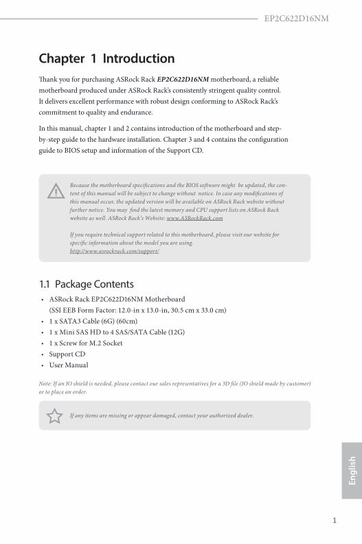
Chapter 1 IntroductionThank you for purchasing ASRock Rack EP2C622D16NM motherboard, a reliable motherboard produced under ASRock Rack’s consistently stringent quality control. It delivers excellent performance with robust design conforming to ASRock Rack’s commitment to quality and endurance.
In this manual, chapter 1 and 2 contains introduction of the motherboard and step-by-step guide to the hardware installation. Chapter 3 and 4 contains the configuration guide to BIOS setup and information of the Support CD.
1.1 Package Contents• ASRock Rack EP2C622D16NM Motherboard
(SSI EEB Form Factor: 12.0-in x 13.0-in, 30.5 cm x 33.0 cm)• 1 x SATA3 Cable (6G) (60cm)• 1 x Mini SAS HD to 4 SAS/SATA Cable (12G)• 1 x Screw for M.2 Socket• Support CD• User Manual
Note: If an IO shield is needed, please contact our sales representatives for a 3D file (IO shield made by customer) or to place an order.
If any items are missing or appear damaged, contact your authorized dealer.
Because the motherboard specifications and the BIOS software might be updated, the con-tent of this manual will be subject to change without notice. In case any modifications of this manual occur, the updated version will be available on ASRock Rack website without further notice. You may find the latest memory and CPU support lists on ASRock Rack website as well. ASRock Rack’s Website: www.ASRockRack.com If you require technical support related to this motherboard, please visit our website for specific information about the model you are using. http://www.asrockrack.com/support/

2 3
English
1.2 Specifications
EP2C622D16NM
MB Physical StatusForm Factor SSI EEBDimension 12'' x 13'' (30.5 cm x 33.0 cm)Processor SystemCPU Intel® Xeon® Scalable ProcessorsSocket Dual Socket P (3647)Chipset Intel® C622System MemoryCapacity 16 DIMM slots Type - 6 Channel memory technology
- Support DDR4 2666/2400 RDIMM and LRDIMM Voltage 1.2VDIMM Sizes RDIMM: 32GB, 16GB, 8GB, 4GB
LRDIMM: 64GB, 32GBExpansion Slot PCIe 3.0 x 16 2 slotsStorageSATA Controller Intel® C622 :
12 x SATA3 + 1 x SATA DOM port + 1 x M.2 port, support RAID 0, 1, 5, 10
OCuLink for U.2 2, x4 from CPU2EthernetMezzanine type A/B/CManagementBMC Controller ASPEED AST2500IPMI Dedicated GLAN
1 x Realtek RTL8211E for dedicated management GLAN
Features Watch Dog NMI
GraphicsController ASPEED AST2500VRAM DDR4 16MBRear Panel I/OVGA Port 1 x D-SubSerial port 1 x COM portUSB 3.0 Port 2LAN Port - 1x RJ45 Gigabit Ethernet LAN port
- LAN Ports with LED (ACT/LINK LED and SPEED LED)
EP2C622D16NM
2 3
Engl
ish
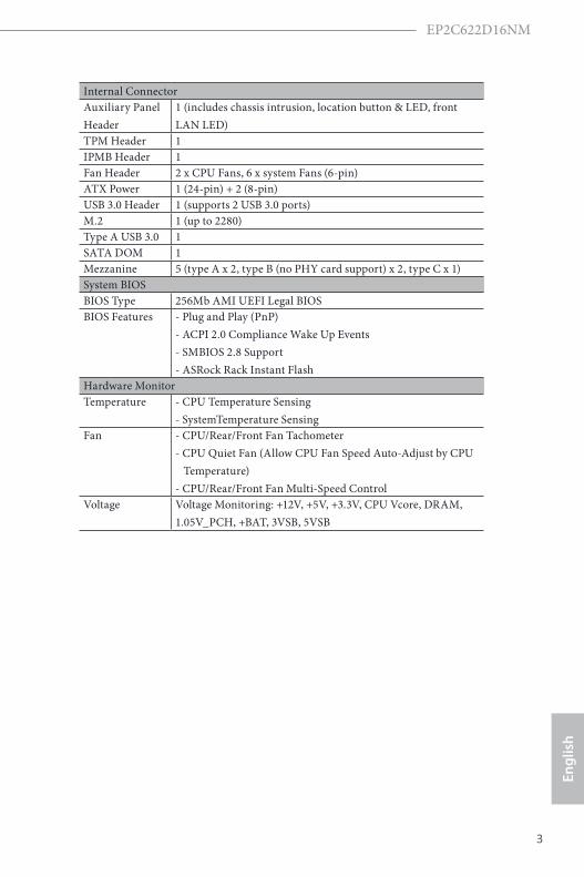
Internal ConnectorAuxiliary Panel Header
1 (includes chassis intrusion, location button & LED, front LAN LED)
TPM Header 1IPMB Header 1Fan Header 2 x CPU Fans, 6 x system Fans (6-pin)ATX Power 1 (24-pin) + 2 (8-pin)USB 3.0 Header 1 (supports 2 USB 3.0 ports)M.2 1 (up to 2280)Type A USB 3.0 1SATA DOM 1Mezzanine 5 (type A x 2, type B (no PHY card support) x 2, type C x 1)System BIOSBIOS Type 256Mb AMI UEFI Legal BIOSBIOS Features - Plug and Play (PnP)
- ACPI 2.0 Compliance Wake Up Events - SMBIOS 2.8 Support - ASRock Rack Instant Flash
Hardware MonitorTemperature - CPU Temperature Sensing
- SystemTemperature SensingFan - CPU/Rear/Front Fan Tachometer
- CPU Quiet Fan (Allow CPU Fan Speed Auto-Adjust by CPU Temperature) - CPU/Rear/Front Fan Multi-Speed Control
Voltage Voltage Monitoring: +12V, +5V, +3.3V, CPU Vcore, DRAM, 1.05V_PCH, +BAT, 3VSB, 5VSB

4 5
English
Support OSOS Microsoft® Windows®
- Server 2012 R2 (64 bit) - Server 2016 (64 bit)
Linux® - CentOS 6.8 (64 bit) / 7. 2 (64 bit) (only supports AHCI mode) - SUSE Enterprise Linux Server 11 SP4 (64 bit) / 12 SP1 (64 bit) - FreeBSD 11 (64 bit) - Fedora Core 24 (64 bit) - Ubuntu 16.04/15.10 (64 bit) - RedHat Enterprise Linux Server 6.8 (64 bit) / 7.2 (64 bit)
Virtual: - VMWare ESXi 6.0 * Please refer to our website for the latest OS support list.
EnvironmentTemperature Operation temperature: 10°C ~ 35°C / Non operation
temperature: -40°C ~ 70°C NOTE: Please refer to our website for the latest specifications.
This motherboard supports Wake from on Board LAN. To use this function, please make sure that the “Wake on Magic Packet from power off state” is enabled in Device Manager > Intel® Ethernet Connection > Power Management. And the “PCI Devices Power On” is enabled in UEFI SETUP UTILITY > Advanced > ACPI Configuration. After that, onboard LAN1&2 can wake up S5 under OS.
If you install Intel® LAN utility or Marvell SATA utility, this motherboard may fail Win-dows® Hardware Quality Lab (WHQL) certification tests. If you install the drivers only, it will pass the WHQL tests.

EP2C622D16NM
4 5
Engl
ish
1.3 Unique Features
ASRock Rack Instant Flash is a BIOS flash utility embedded in Flash ROM. This con-venient BIOS update tool allows you to update system BIOS without entering operat-ing systems first like MS-DOS or Windows®. With this utility, you can press the <F6> key during the POST or the <F2> key to enter into the BIOS setup menu to access ASRock Rack Instant Flash. Just launch this tool and save the new BIOS file to your USB flash drive, floppy disk or hard drive, then you can update your BIOS only in a few clicks without preparing an additional floppy diskette or other complicated flash utility. Please be noted that the USB flash drive or hard drive must use FAT32/16/12
file system.

6 7
English
1.4 Motherboard Layout
33.02 cm (13 in)
VG
A1
US
B 3
.0T: U
SB
2B
: US
B1
DDR4_A2 (64 bit, 288-pin module, White)
DDR4_A1 (64 bit, 288-pin module, Blue)
DDR4_B1 (64 bit, 288-pin module, Blue)
DDR4_C1 (64 bit, 288-pin module, Blue)
IntelC622
DDR4_F1 (64 bit, 288-pin module, Blue)
DDR4_E1 (64 bit, 288-pin module, Blue)
DDR4_D1 (64 bit, 288-pin module, Blue)
DDR4_D2 (64 bit, 288-pin module, White)
DDR4_L1 (64 bit, 288-pin module, Blue)
DDR4_K1 (64 bit, 288-pin module ), Blue
DDR4_J1 (64 bit, 288-pin module ), Blue
DDR4_J2 (64 bit, 288-pin module ), White
DDR4_G2 (64 bit, 288-pin module, White)
DDR4_G1 (64 bit, 288-pin module, Blue)
DDR4_H1 (64 bit, 288-pin module, Blue)
DDR4_I1 (64 bit, 288-pin module, Blue)
RoHS
IPM
I_L
AN
ATX12V1
1HDLED RESET
PLED PWRBTN
PANEL1
11AUX_PANEL1 SPEAKER
BATTERY1
PCIE7
(White)PCIE6
(Blue)
Dr.Debug
52
1
FRNT_VGA1
M2
_1
11
ATX12V2
12
18
20
21
22
29
28
REAR_FAN1
REAR_FAN2
CPU1_FAN1
FRNT_FAN1
FRNT_FAN2
FRNT_FAN3
FRNT_FAN4
CPU2_FAN1
1
USB3_3_4 USB3_5
1 1 1TPM1
1
NMI_BTN1
OCU1
OCU2
MEZZ_MB_A2
11 1 1 1
MEZZ_MB_B2
MEZZ_MB_A1
MEZZ_MB_B1
MEZZ_1_C1
BMC
SuperI/O
1FRONT_LED_LAN34
UID1
SSATA_0_3
SATA_0_7
SSATA_4
ATXPWR1
1PSU_SMB1
11
1 11
PMBUS_SEL_DAT1PMBUS_SEL_ALT1
SATAPWR1
NCSI_SEL1
BIOSROM
1 2 3 4 5 6 7 10
BMC_SMB_1 IPMB_1
CHASSIS_ID2CHASSIS_ID1
CHASSIS_ID0
ME_RECOVERY1
T 1R
NUT30 NUT42 NUT60 NUT80
8 9
13
14
15
16
17
19
23
24
25
26
27
30
313233343536373839404142
44
43
45
46
47
48
49
56
57
EP2C622D16NM
CPU2
CPU1
30
.5 c
m (
12
in
)
1
PECI1
53
PMBUS_SEL_CLK1
55
54
51
50

EP2C622D16NM
6 7
Engl
ish
No. Description
1 Mini-SAS HD Connector (SSATA_0_3)**
2 Mini-SAS HD Connector (SATA_0_7)
3 PMBUS Mode Jumper (PMBUS_SEL_ALT1)
4 SATA DOM Power Jumper (SATAPWR1)
5 SATA DOM Connector, Red (SSATA_4)**
6 PMBUS Mode Jumper (PMBUS_SEL_CLK1)
7 NCSI Mode Jumper (NCSI_SEL1)
8 ATX Power Connector (ATXPWR1)
9 PSU SMBus (PSU_SMB1)
10 PMBUS Mode Jumper (PMBUS_SEL_DAT1)
11 3 x 288-pin DDR4 DIMM Slots (DDR4_A1, DDR4_B1, DDR4_C1, Blue)*
12 1 x 288-pin DDR4 DIMM Slots (DDR4_A2, White)*
13 ATX 12V Power Connector (ATX12V1)
14 LGA 3647 CPU Socket P0 (CPU1)
15 Rear Fan Connector (REAR_FAN1)
16 Rear Fan Connector (REAR_FAN2)
17 CPU1 Fan Connector (CPU1_FAN1)
18 1 x 288-pin DDR4 DIMM Slots (DDR4_D2, White)*
19 3 x 288-pin DDR4 DIMM Slots (DDR4_D1, DDR4_E1, DDR4_F1, Blue)*
20 3 x 288-pin DDR4 DIMM Slots (DDR4_G1, DDR4_H1, DDR4_I1, Blue)*
21 1 x 288-pin DDR4 DIMM Slots (DDR4_G2, White)*
22 Front Fan Connector (FRNT_FAN1)
23 Front Fan Connector (FRNT_FAN2)
24 Front Fan Connector (FRNT_FAN3)
25 LGA 3647 CPU Socket P0 (CPU2)
26 Front Fan Connector (FRNT_FAN4)
27 CPU2 Fan Connector (CPU2_FAN1)
28 ATX 12V Power Connector (ATX12V2)
29 1 x 288-pin DDR4 DIMM Slots (DDR4_J2, White)*
30 3 x 288-pin DDR4 DIMM Slots (DDR4_J1, DDR4_K1, DDR4_L1, Blue)*
31 OCuLink x4 Connector (OCU2)
32 OCuLink x4 Connector (OCU1)
33 Non Maskable Interrupt Button (NMI_BTN1)

8 9
English
No. Description
34 Speaker Header (SPEAKER1)
35 System Panel Header (PANEL1)
36 Auxiliary Panel Header (AUX_PANEL1)
37 Thermal Sensor Header (TR1)
38 TPM Header (TPM1)
39 Intelligent Platform Management Bus header (IPMB1)
40 Chassis ID1 Jumper (CHASSIS_ID1)
41 BMC SMBus Header (BMC_SMB_1)
42 Vertical Type A USB 3.0 (USB3_5)
43 BMC SMBus Header 1 (BMC_SMB1)
44 Chassis ID2 Jumper (CHASSIS_ID2)
45 Chassis ID0 Jumper (CHASSIS_ID0)
46 Mezzanine Slot (MEZZ_MB_A2)***
47 ME Recovery Jumper (ME_RECOVERY1)
48 CPU PECI Mode Jumper (PECI1)
49 Mezzanine Slot (MEZZ_MB_B2)***
50 M.2 Slot (M2_2)
51 PCI Express 3.0 Slot (PCIE6)
52 PCI Express 3.0 Slot (PCIE7)
53 Mezzanine Slot (MEZZ_MB_A1)
54 Mezzanine Slot (MEZZ_1_C1)
55 Mezzanine Slot (MEZZ_MB_B1)
56 Front LAN LED Header (FRONT_LED_LAN34)
57 Front VGA Header (FRONT_VGA1)*For DIMM installation and configuration instructions, please see p.17 (Installation of Memory Modules (DIMM)) for more details.
** The first “S“ of the “SSATA” means “secondary”. SATA is managed by the first controller. SSATA is managed by the secondary controller.
*** Only supports ASRockRack storage cards.

EP2C622D16NM
8 9
Engl
ish
1.5 Onboard LED Indicators
VG
A1
US
B 3
.0T: U
SB
2B
: US
B1
DDR4_A2 (64 bit, 288-pin module, White)
DDR4_A1 (64 bit, 288-pin module, Blue)
DDR4_B1 (64 bit, 288-pin module, Blue)
DDR4_C1 (64 bit, 288-pin module, Blue)
IntelC622
DDR4_F1 (64 bit, 288-pin module, Blue)
DDR4_E1 (64 bit, 288-pin module, Blue)
DDR4_D1 (64 bit, 288-pin module, Blue)
DDR4_D2 (64 bit, 288-pin module, White)
DDR4_L1 (64 bit, 288-pin module, Blue)
DDR4_K1 (64 bit, 288-pin module ), Blue
DDR4_J1 (64 bit, 288-pin module ), Blue
DDR4_J2 (64 bit, 288-pin module ), White
DDR4_G2 (64 bit, 288-pin module, White)
DDR4_G1 (64 bit, 288-pin module, Blue)
DDR4_H1 (64 bit, 288-pin module, Blue)
DDR4_I1 (64 bit, 288-pin module, Blue)
RoHS
IPM
I_L
AN
111
BATTERY1
PCIE7
(White)PCIE6
(Blue)
Dr.Debug
1
M2
_1
11 1 1
1
MEZZ_MB_A2
11 1 1 1
MEZZ_MB_B2
MEZZ_MB_A1
MEZZ_MB_B1
MEZZ_1_C1
BMC
SuperI/O
1
UID1
ATXPWR1
1
11
1 11
BIOSROM
1
2
3
4
NUT30 NUT42 NUT60 NUT80
EP2C622D16NM
SB_PWR1
5
6
7
8
9
BMC_LED1
1
10
FFAN_LED1
FFAN_LED2
CPU_FAN_LED2
FFAN_LED3
FFAN_LED4
CPU_FAN_LED1
RFAN_LED3
RFAN_LED4

10 11
English
No. Item Status Description
1 SB_PWR1 Green STB PWR ready
2 RFAN_LED1 Amber Rear_FAN1 failed
3 RFAN_LED2 Amber Rear_FAN2 failded
4 CPU_FAN_LED1 Amber CPU1_FAN failed
5 FFAN_LED1 Amber FRNT_FAN1 failed
6 FFAN_LED2 Amber FRNT_FAN2 failed
7 FFAN_LED3 Amber FRNT_FAN3 failed
8 FFAN_LED4 Amber FRNT_FAN4 failed
9 CPU_FAN_LED2 Amber CPU2_FAN failed
10 BMC_LED1 Green BMC heartbeat LED

EP2C622D16NM
10 11
Engl
ish
1.6 I/O Panel
3 41
2
No. Description No. Description
1 USB 3.0 Ports (USB3_1_2) 3 VGA Port (VGA1)
2 LAN RJ-45 Port (IPMI_LAN1)* 4 UID Switch (UID)
LAN Port LED Indications
*There are two LED next to the LAN port. Please refer to the table below for the LAN port LED indications.
Dedicated IPMI LAN Port LED Indications
Activity / Link LED Speed LED
Status Description Status DescriptionOff No Link Off 10M bps connection or no
linkBlinking Yellow Data Activity Yellow 100M bps connectionOn Link Green 1G bps connection
ACT/LINK LED
SPEED LED
LAN Port

12 13
English
1.7 Block Diagram

EP2C622D16NM
12 13
Engl
ish
Chapter 2 Installation
This is a SSI EEB form factor (12” x 13”, 30.5 cm x 33.0 cm) motherboard. Before you install the motherboard, study the configuration of your chassis to ensure that the motherboard fits into it.
EP2C622D16NM is a dual socket motherboard that supports Intel® Xeon® Scalable Processors. Please install a primary processor (BootStrap Processor) into “CPU1” socket and then install a non-Primary Processor (Application Processors) into “CPU2” socket. *For a single CPU, please install it into “CPU1” socket (framed by a square).
2.1 Screw HolesPlace screws into the holes indicated by circles to secure the motherboard to the chassis.
2.2 Pre-installation PrecautionsTake note of the following precautions before you install motherboard components or change any motherboard settings.1. Unplug the power cord from the wall socket before touching any components.2. To avoid damaging the motherboard’s components due to static electricity, NEVER
place your motherboard directly on the carpet or the like. Also remember to use a grounded wrist strap or touch a safety grounded object before you handle the compo-nents.
3. Hold components by the edges and do not touch the ICs. 4. Whenever you uninstall any component, place it on a grounded anti-static pad or in
the bag that comes with the component.5. When placing screws into the screw holes to secure the motherboard to the chassis,
please do not over-tighten the screws! Doing so may damage the motherboard.
Make sure to unplug the power cord before installing or removing the motherboard. Failure to do so may cause physical injuries to you and damages to motherboard components.
Do not over-tighten the screws! Doing so may damage the motherboard.
Before you install or remove any component, ensure that the power is switched off or the power cord is detached from the power supply. Failure to do so may cause severe damage to the motherboard, peripherals, and/or components.

14 15
English
2.3 Installing the CPU and Heatsink
1. Before you insert the CPU into the socket, please check if the PnP cap is on the socket, if the CPU surface is unclean, or if there are any bent pins in the socket. Do not force to insert the CPU into the socket if above situation is found. Otherwise, the CPU will be seriously damaged.
2. Unplug all power cables before installing the CPU.
1
2

EP2C622D16NM
14 15
Engl
ish
1. Before you installed the heatsink, you need to spray thermal interface material between the CPU and the heatsink to improve heat dissipation.
2. Illustration in this documentation are examples only. Heatsink or fan cooler type may differ.
3
4
180o

16 17
English
5

EP2C622D16NM
16 17
Engl
ish
6
CPU_FAN
Tighten the two Middle Nuts to 12 IN.LB. Two turns at a time.
Tighten the two Corner Plungerto 12 IN.LB.Two turns at a time.
6-1
6-2
6-3
6-4
7

18 19
English
2.4 Installation of Memory Modules (DIMM)This motherboard provides sixteen 288-pin DDR4 (Double Data Rate 4) DIMM slots in two groups, and supports Six and Dual Channel Memory Technology.
Capacity CPU1 CPU2
256GB / 512GB
DDR4_A1, B1, C1, D1, E1, F1 (Blue) DDR4_G1, H1, I1, J1, K1, L1 (Blue)
DDR4_A2, D2 (White) DDR4_G2, J2 (White)
1. It is not allowed to install a DDR, DDR2 or DDR3 memory module into a DDR4 slot; otherwise, this motherboard and DIMM may be damaged.
2. For dual channel configuration, you always need to install identical (the same brand, speed, size and chip-type) DDR4 DIMM pairs.
3. It is unable to activate Dual Channel Memory Technology with only one or three memory module installed.
4. Some DDR4 1GB double-sided DIMMs with 16 chips may not work on this motherboard. It is not recommended to install them on this motherboard.
DD
R4-
_L1
DD
R4_
K1
DD
R4_
J1
DD
R4_
J2
DD
R4_
G2
DD
R4_
G1
DD
R4_
H1
DD
R4_
I1
DD
R4_
F1
DD
R4_
E1
DD
R4_
D1
DD
R4_
D2
DD
R4_
A2
DD
R4_
A1
DD
R4_
B1
DD
R4_
C1
CPU1 CPU2

EP2C622D16NM
18 19
Engl
ish
The DIMM only fits in one correct orientation. It will cause permanent damage to the motherboard and the DIMM if you force the DIMM into the slot at incorrect orientation.
1
2
3

20 21
English
Recommended Memory Configurations
A single memory module should be installed in the BLUE socket which is nearest to the CPU.
1 CPU Configuration
CPU1
A1 A2 B1 C1 D1 D2 E1 F1
1 DIMM #
2 DIMMS # #
4 DIMMS # # # #
6 DIMMS # # # # # #
8 DIMMS # # # # # # # #
2 CPU Configuration
CPU1
A1 A2 B1 C1 D1 D2 E1 F1
1 DIMM #
2 DIMMS #
4 DIMMS # #
8 DIMMS # # # #
16 DIMMS # # # # # # # #
CPU2
G1 G2 H1 I1 J1 J2 K1 L1
1 DIMM
2 DIMMS #
4 DIMMS # #
8 DIMMS # # # #
16 DIMMS # # # # # # # #
Note: "#" indicates the socket is populated with a memory module.

EP2C622D16NM
20 21
Engl
ish
2.5 Expansion Slots (PCI Express Slots)There are 2 PCI Express slots on this motherboard.
PCIE slot: PCIE6 (PCIE 3.0 x16 slot, from CPU 2) is used for PCI Express x16 lane width cards. PCIE7 (PCIE 3.0 x16 slot, from CPU 1) is used for PCI Express x16 lane width cards.
Slot Generation Mechanical Electrical Source
PCIE 7 3.0 x16 x16 CPU 1
PCIE 6 3.0 x16 x16 CPU 2
Installing an expansion card
Step 1. Before installing an expansion card, please make sure that the power supply is switched off or the power cord is unplugged. Please read the documentation of the expansion card and make necessary hardware settings for the card before you start the installation.Step 2. Remove the system unit cover (if your motherboard is already installed in a chassis).Step 3. Remove the bracket facing the slot that you intend to use. Keep the screws for later use.Step 4. Align the card connector with the slot and press firmly until the card is completely seated on the slot.Step 5. Fasten the card to the chassis with screws.
Step 6. Replace the system cover.

22 23
English
2.6 Jumper Setup
The illustration shows how jumpers are setup. When the jumper cap is placed on the pins, the jumper is “Short”. If no jumper cap is placed on the pins, the jumper is “Open”. The illustration shows a 3-pin jumper whose pin1 and pin2 are “Short” when a jumper cap is placed on these 2 pins.
ME Recovery Jumper(3-pin ME_RECOVERY1)(see p.6, No. 47)
Normal Mode (Default)
ME Recovery Mode
PMBUS Mode Jumper(3-pin PMBUS_SEL_CLK1) (see p.6, No. 6)(3-pin PMBUS_SEL_DAT1) (see p.6, No. 10)(3-pin PMBUS_SEL_ALT1)(see p.6, No. 3)
PMBus connected to BMC (Default)
PMBus connected to PCH
NCSI Mode Jumper (3-pin NCSI_SEL1)(see p.6, No. 7)
NCSI is set to onboardLAN1 (Default)
NCSI is set to MezzanineCard

EP2C622D16NM
22 23
Engl
ish
Chassis ID0 Jumper(3-pin CHASSIS_ID0)(see p.6, No. 45)Chassis ID1 Jumper(3-pin CHASSIS_ID1)(see p.6, No. 40)Chassis ID2 Jumper(3-pin CHASSIS_ID2)(see p.6, No. 44)
Board Level SKU (Default) Reserved for system level use
Chassis ID0 Jumper(3-pin CHASSIS_ID0)(see p.6, No. 45)Chassis ID1 Jumper(3-pin CHASSIS_ID1)(see p.6, No. 40)Chassis ID2 Jumper(3-pin CHASSIS_ID2)(see p.6, No. 44)
Reserved for system level use
Reserved for system level use
Chassis ID0 Jumper(3-pin CHASSIS_ID0)(see p.6, No. 45)Chassis ID1 Jumper(3-pin CHASSIS_ID1)(see p.6, No. 40)Chassis ID2 Jumper(3-pin CHASSIS_ID2)(see p.6, No. 44)
Reserved for system level use
Reserved for system level use

24 25
English
Chassis ID0 Jumper(3-pin CHASSIS_ID0)(see p.6, No. 45)Chassis ID1 Jumper(3-pin CHASSIS_ID1)(see p.6, No. 40)Chassis ID2 Jumper(3-pin CHASSIS_ID2)(see p.6, No. 44)
Reserved for system level use
Reserved for system level use
SATA DOM Power Jumper (3-pin SATAPWR1)(see p.6, No. 4)
SATA DOM (SSATA_4) requires 5V power supply
SATA DOM (SSATA_4) does NOT require 5V power supply (Default)
Consult the documentation that comes with your SATA DOM and check whether or not Pin 7 requires 5V power supply. If the connected SATA DOM requires 5V power supply, move the jumper caps placed on the SATA DOM Power Jumper (SATAPWR1) from pins 2-3 (default) to pins 1-2. If the connected SATA DOM does NOT require 5V power supply, connect the SATA DOM power cable to the SATA DOM power header (SATA_PWR1) and there is no need to change the default jumper setting of the SATA DOM Power Jumper (pins 2-3). Warning! Incorrect setting of the SATA DOM Power Jumper (SATAPWR1) may cause dam-age to the motherboard or your SATA DOM.

EP2C622D16NM
24 25
Engl
ish
2.7 Onboard Headers and Connectors
System Panel Header(9-pin PANEL1)(see p.6, No. 35)
GND
RESET#
PWRBTN#
PLED-
PLED+
GND
HDLED-
HDLED+
1
GND
Connect the power switch, reset switch and system status indicator on the chassis to this header according to the pin assignments. Particularly note the positive and negative pins before connecting the cables.
PWRBTN (Power Switch): Connect to the power switch on the chassis front panel. You may configure the way to turn off your system using the power switch.
RESET (Reset Switch): Connect to the reset switch on the chassis front panel. Press the reset switch to restart the computer if the computer freezes and fails to perform a normal restart.
PLED (System Power LED): Connect to the power status indicator on the chassis front panel. The LED is on when the system is operating. The LED is off when the system is in S4 sleep state or powered off (S5).
HDLED (Hard Drive Activity LED): Connect to the hard drive activity LED on the chassis front panel. The LED is on when the hard drive is reading or writing data.
The front panel design may differ by chassis. A front panel module mainly consists of power switch, reset switch, power LED, hard drive activity LED, speaker and etc. When connect-ing your chassis front panel module to this header, make sure the wire assignments and the pin assignments are matched correctly.
Onboard headers and connectors are NOT jumpers. Do NOT place jumper caps over these headers and connectors. Placing jumper caps over the headers and connectors will cause permanent damage to the motherboard.

26 27
English
Auxiliary Panel Header(18-pin AUX PANEL_1) (see p.6, No. 36)
GN
D
SM
B_C
LK
SM
B_A
lert
CA
SE
OP
EN
1
SM
B_D
AT
A
+3V
SB
LAN
1_LI
NK
LED
_PW
R
LAN
2_LI
NK
LED
_PW
R
+5V
SB
GN
D
GN
D
LOC
ATO
RLE
D1+
LOC
ATO
RLE
D1-
LOC
ATO
RB
TN
#
Sys
tem
Fau
lt LE
D-
A B
C D Sys
tem
Fau
lt LE
D+
E
This header supports multiple functions on the front panel, including the front panel SMB, internet status indicator and chassis intrusion pin.
Serial ATA3 Connector(SSATA_4) (see p.6, No. 5)
SSATA_4 The SATA3 connector supports SATA data cables for internal storage devices with up to 6.0 Gb/s data transfer rate.
A. Front panel SMBus connecting pin (6-1 pin FPSMB) This header allows you to connect SMBus (System Management Bus) equipment. It can be used for communication between peripheral equipment in the system, which has slower transmission rates, and power management equipment. B. Internet status indicator (2-pin LAN1_LED, LAN2_LED) These two 2-pin headers allow you to use the Gigabit internet indicator cable to connect to the LAN status indicator. When this indicator flickers, it means that the internet is prop-erly connected. C. Chassis intrusion pin (2-pin CHASSIS) This header is provided for host computer chassis with chassis intrusion detection designs. In addition, it must also work with external detection equipment, such as a chassis intru-sion detection sensor or a microswitch. When this function is activated, if any chassis component movement occurs, the sensor will immediately detect it and send a signal to this header, and the system will then record this chassis intrusion event. The default setting is set to the CASEOPEN and GND pin; this function is off. D. Locator LED (4-pin LOCATOR) This header is for the locator switch and LED on the front panel. E. System Fault LED (2-pin LOCATOR) This header is for the Fault LED on the system.

EP2C622D16NM
26 27
Engl
ish
Mini-SAS HD Connectors(SATA_0_7)(see p.6, No. 2) (SSATA_0_3)(see p.6, No. 1)
SSATA_0_3
SATA_0_7
These connectors support MiniSAS-to-SATA data cables for internal storage devices with up to 6.0 Gb/s data transfer rate.
USB 3.0 Connector(USB3_5)(see p.6, No. 42)
USB 3.0 Header(19-pin USB3_3_4)(see p.6, No. 43)
Besides two default USB 3.0 ports on the I/O panel, there is one USB 3.0 header on this motherboard. This USB 3.0 header can support two USB 3.0 ports.
Chassis Speaker Header(4-pin SPEAKER1)(see p.6, No. 34)
1
+5V
DUMMY
DUMMY
SPEAKER Please connect the chassis speaker to this header.
1
Dummy
GND
GND
Vbus
GND
GNDIntA_PA_SSRX+
Vbus
IntA_PA_D+IntA_PA_D-
IntA_PA_SSTX+IntA_PA_SSTX-
IntA_PA_SSRX-
IntA_PB_SSRX-IntA_PB_SSRX+
IntA_PB_SSTX-IntA_PBA_SSTX+
IntA_PB_D-IntA_PB_D+

28 29
English
Front and Rear Fan Con-nectors(6-pin FRNT_FAN1)(see p.6, No. 22)(6-pin FRNT_FAN2)(see p.6, No. 23)(6-pin FRNT_FAN3)(see p.6, No. 24)(6-pin FRNT_FAN4)(see p.6, No. 26)
(6-pin REAR_FAN1)(see p.6, No. 15)(6-pin REAR_FAN2)(see p.6, No. 16)
FAN_SPEED
FAN_SPEED_CONTROL
FAN_VOLTAGEGND
1 2 3 4 5 6
SENSORNC
FAN_SPEEDFAN_SPEED_CONTROL
FAN_VOLTAGEGND
6 5 4 3 2 1
SENSORNC
Please connect fan cables to the fan connectors and match the black wire to the ground pin. All fans support Fan Control.
CPU Fan Connectors(6-pin CPU1_FAN1)(see p.6, No. 17)(6-pin CPU2_FAN1)(see p.6, No. 27)
FAN_SPEED
FAN_SPEED_CONTROL
FAN_VOLTAGEGND
1 2 3 4 5 6
SENSORNC This motherboard provides
t wo 6 -Pi n CPU fa n (Qu iet Fan) connectors. If you plan to connect a 3-Pin CPU fan, please connect it to Pin 1-3.*For more details, please refer to the Cooler QVL list on the ASRock Rack website.
ATX Power Connector(24-pin ATXPWR1)(see p.6, No. 8)
1
3V3V
GN
D
GN
D 5V5V
GN
D
PW
RO
K_P
S
5VS
B
12V12V3V
3V-12V
GN
DP
SO
N#
GN
D
GN
D
GN
D
5V5V5VGN
D
N/A
12
24 13
This motherboard provides a 24-pin ATX power connector. To use a 20-pin ATX power supply, please plug it along Pin 1 and Pin 13.

EP2C622D16NM
28 29
Engl
ish
ATX 12V Power Connectors(8-pin ATX12V1)(see p.6, No. 13)(8-pin ATX12V2)(see p.6, No. 28)
4
8
1
5
+12V2
GND
4
8
1
5
+12V2
GND
This motherboard provides two 8-pin ATX 12V power connectors.
TPM Header(17-pin TPM1)(see p.6, No. 38)
1L
FR
AM
E#
_L
CK
_3
3M
_T
PM
TP
M_
RS
T#
LA
D3
_L
+3
V
LA
D0
_L
+3
VS
B
GN
DF
_C
LK
RU
N#
SE
RIR
Q#
S_
PW
RD
WN
#
GN
D
LA
D1
_L
LA
D2
_L
SM
B_
DA
TA
_M
AIN
SM
B_
CL
K_
MA
IN
GN
D
This connector supports Trusted Platform Module (TPM) system, which can securely store keys, digital certificates, passwords, and data. A TPM system also helps enhance network security, protects digital identities, and ensures platform integrity.
PSU SMBus Header(5-pin PSU_SMB1)(see p.6, No. 9)
+3VSB
1
GND
ALERTSMBCLK
SMBDATA
PSU SMBus monitors the status of the power supply, fan and system temperature.
Intelligent Platform Management Bus Header(4-pin IPMB1)(see p.6, No. 39)
IPMB_SDA
IPMB_SCL
No ConnectGND
This 4-pin connector is used to provide a cabled base-board or front panel connection for value added features and 3rd-party add-in cards, such as Emergency Management cards, that provide management features using the IPMB.
Baseboard Management Controller SMBus Header(5-pin BMC_SMB1)(see p.6, No. 41)
BMC_SMB_PRESENT_1_N
Power
BMC_SMBCLK
GND
BMC_SMBDATA
The header is used for the SM BUS devices.

30 31
English
Thermal Sensor Header(3-pin TR1)(see p.6, No. 37)
1
TR1 TR1
GND
Please connect the thermal sensor cable to either pin 1-2 or pin 2-3 and the other end to the device which you wish to monitor its temperature.
Front VGA Header(15-pin FRNT_VGA1)(see p.6, No. 57)
1
GND
Green
DDC_DATA
V_SYNC
Red
DDC_CLK
GND
+5V
H_SYNC
GND
GND
GND
Blue
Please connect either end of VGA_2X8 cable to VGA header.
Non Maskable Interrupt Button Header(NMI_BTN1)(see p.6, No. 33)
1
CONTROL
GNDPlease connect a NMI deviceto this header.
OCuLink Connectors (OCU1)(see p.6, No. 32) (OCU2)(see p.6, No. 31)
OCU1
OCU2
Please connect PCIE SSDs to these connectors.
Front LAN LED Header (FRONT_LED_LAN34) (see p.6, No. 56)
1
LAN4_LINK
LED_PWR
LED_PWRLAN3_LINK
This 4-pin connector is used for the front LAN status indicator.

EP2C622D16NM
30 31
Engl
ish
2.8 Dr. DebugDr. Debug is used to provide code information, which makes troubleshooting even easier. Please see the diagrams below for reading the Dr. Debug codes.
Code Description
00 Please check if the CPU is installed correctly and then clear CMOS.
0dProblem related to memory, VGA card or other devices. Please clear CMOS, re-install the memory and VGA card, and remove other USB, PCI devices.
01 - 54(except 0d),
5A- 60
Problem related to memory. Please re-install the CPU and memory then clear CMOS. If the problem still exists, please install only one memory module or try using other memory modules.
55The Memory could not be detected. Please re-install the memory and CPU. If the problem still exists, please install only one memory module or try using other memory modules.
61 - 91 Chipset initialization error. Please press reset or clear CMOS.
92 - 99Problem related to PCI-E devices. Please re-install PCI-E devices or try installing them in other slots. If the problem still exists, please remove all PCI-E devices or try using another VGA card.
A0 - A7Problem related to IDE or SATA devices. Please re-install IDE and SATA devices. If the problem still exists, please clear CMOS and try removing all SATA devices.
b0Problem related to memory. Please re-install the CPU and memory. If the problem still exists, please install only one memory module or try using other memory modules.
b4 Problem related to USB devices. Please try removing all USB devices.
b7Problem related to memory. Please re-install the CPU and memory then clear CMOS. If the problem still exists, please install only one memory module or try using other memory modules.
d6The VGA could not be recognized. Please clear CMOS and try re-installing the VGA card. If the problem still exists, please try installing the VGA card in other slots or use other VGA cards.
d7The Keyboard and mouse could not be recognized. Please try re-installing the keyboard and mouse.
d8 Invalid Password.
FF Please check if the CPU is installed correctly and then clear CMOS.

32 33
English
2.9 Unit Identification purpose LED/SwitchWith the UID button, You are able to locate the server you’re working on from behind a rack of servers.
Unit Identification purpose LED/Switch(UID1)
When the UID button on the front or rear panel is pressed, the front/rear UID blue LED indicator will be truned on. Press the UID button again to turn off the indicator.
2.10 Driver Installation GuideTo install the drivers to your system, please insert the support CD to your optical drive first. Then, the drivers compatible to your system can be auto-detected and listed on the support CD driver page. Please follow the order from top to bottom to install those required drivers. Therefore, the drivers you install can work properly.
EP2C622D16NM
32 33
Engl
ish
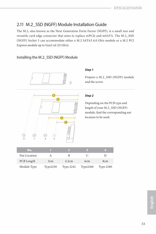
2.11 M.2_SSD (NGFF) Module Installation GuideThe M.2, also known as the Next Generation Form Factor (NGFF), is a small size and versatile card edge connector that aims to replace mPCIe and mSATA. The M.2_SSD (NGFF) Socket 3 can accommodate either a M.2 SATA3 6.0 Gb/s module or a M.2 PCI Express module up to Gen3 x4 (32 Gb/s).
Installing the M.2_SSD (NGFF) Module
Step 1
Prepare a M.2_SSD (NGFF) module and the screw.
3
2
4
BCD A
1
Step 2
Depending on the PCB type and length of your M.2_SSD (NGFF) module, find the corresponding nut location to be used.
No. 1 2 3 4
Nut Location A B C D
PCB Length 3cm 4.2cm 6cm 8cm
Module Type Type2230 Type 2242 Type2260 Type 2280

34 35
English
BCD A
Step 3
Move the standoff based on the module type and length. The standoff is placed at the nut location D by default. Skip Step 3 and 4 and go straight to Step 5 if you are going to use the default nut. Otherwise, release the standoff by hand.
BCD A
Step 4
Peel off the yellow protective film on the nut to be used. Hand tighten the standoff into the desired nut location on the motherboard.
BC A
ABCD
Step 5
Align and gently insert the M.2 (NGFF) SSD module into the M.2 slot. Please be aware that the M.2 (NGFF) SSD module only fits in one orientation.
NUT1NUT2D
Step 6
Tighten the screw with a screwdriver to secure the module into place. Please do not overtighten the screw as this might damage the module.
For the latest updates of M.2_SSD (NFGG) module support list, please visit our website for details: http://www.asrockrack.com

EP2C622D16NM
34 35
Engl
ish
Chapter 3 UEFI Setup Utility
3.1 IntroductionTh is section explains how to use the UEFI SETUP UTILITY to confi gure your system. Th e UEFI chip on the motherboard stores the UEFI SETUP UTILITY. You may run the UEFI SETUP UTILITY when you start up the computer. Please press <F2> or <Del> during the Power-On-Self-Test (POST) to enter the UEFI SETUP UTILITY; otherwise, POST will continue with its test routines.If you wish to enter the UEFI SETUP UTILITY aft er POST, restart the system by pressing <Ctrl> + <Alt> + <Delete>, or by pressing the reset button on the system chassis. You may also restart by turning the system off and then back on.
3.1.1 UEFI Menu Bar
Th e top of the screen has a menu bar with the following selections:
Item Description
Main To set up the system time/date information
Advanced To set up the advanced UEFI features
Security To set up the security features
BootTo set up the default system device to locate and load the Operating System
Event Logs For event log confi guration
Server Mgmt To manage the server
Exit To exit the current screen or the UEFI SETUP UTILITY
Use < > key or < > key to choose among the selections on the menu bar, and then press <Enter> to get into the sub screen.
Because the UEFI soft ware is constantly being updated, the following UEFI setup screens and descriptions are for reference purpose only, and they may not exactly match what you see on your screen.
Use < > key or < > key to choose among the selections on the menu bar, and Use < > key or < > key to choose among the selections on the menu bar, and

36 37
English
3.1.2 Navigation Keys
Please check the following table for the function description of each navigation key.
Navigation Key(s) Function Description
/ Moves cursor left or right to select Screens
/ Moves cursor up or down to select items
+ / - To change option for the selected items
<Tab> Switch to next function
<Enter> To bring up the selected screen
<PGUP> Go to the previous page
<PGDN> Go to the next page
<HOME> Go to the top of the screen
<END> Go to the bottom of the screen
<F1> To display the General Help Screen
<F7> Discard changes and exit the UEFI SETUP UTILITY
<F9> Load optimal default values for all the settings
<F10> Save changes and exit the UEFI SETUP UTILITY
<F12> Print screen
<ESC> Jump to the Exit Screen or exit the current screen
EP2C622D16NM
36 37
Engl
ish
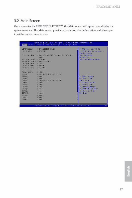
3.2 Main ScreenOnce you enter the UEFI SETUP UTILITY, the Main screen will appear and display the system overview. The Main screen provides system overview information and allows you to set the system time and date.

38 39
EnglishSetting wrong values in this section may cause the system to malfunction.
3.3 Advanced ScreenIn this section, you may set the configurations for the following items: CPU Configuration, DRAM Configuration, Chipset Configuration, Storage Configuration, ACPI Configura-tion, USB Configuration, Super IO Configuration, Serial Port Console Redirection, H/W Monitor, Runtime Error Logging, Intel SPS Configuration, Intel(R) VMD Technology, Intel(R) Virtual RAID on CPU and Instant Flash.

EP2C622D16NM
38 39
Engl
ish
3.3.1 CPU Configuration
Intel SpeedStep Technology
Intel SpeedStep technology allows processors to switch between multiple frequencies and voltage points for better power saving and heat dissipation. CPU turbo ratio can be fixed when Intel SpeedStep Technology set Disabled and Intel Turbo Boost Technology set En-abled.
Please note that enabling this function may reduce CPU voltage and lead to system stability or compatibility issues with some power supplies. Please set this item to [Disabled] if above issues occur.
Intel Turbo Boost Technology
Intel Turbo Boost Technology enables the processor to run above its base operating fre-quency when the operating system requests the highest performance state.
Long Duration Power Limit
Configure Package Power Limit 1 in watts. When the limit is exceeded, the CPU ratio will be lowered after a period of time. A lower limit can protect the CPU and save power, while a higher limit may improve performance.
Long Duration Maintained
Configure the period of time until the CPU ratio is lowered when the Long Duration Power

40 41
English
Limit is exceeded.
Short Duration Power Limit
Configure Package Power Limit 2 in watts. When the limit is exceeded, the CPU ratio will be lowered immediately. A lower limit can protect the CPU and save power, while a higher limit may improve performance.
Intel Hyper Threading Technology
Intel Hyper Threading Technology allows multiple threads to run on each core, so that the overall performance on threaded software is improved.
Active Processor 1 Cores
Select the number of cores to enable in each processor package.
Active Processor 2 Cores
Select the number of cores to enable in each processor package.
No-Execute Memory Protection
Processors with No-Execution Memory Protection Technology may prevent certain classes of malicious buffer overflow attacks.
Enable Intel TXT Support
Enables Intel Trusted Execution Technology Configuration.
Intel Virtualization Technology
Intel Virtualization Technology allows a platform to run multiple operating systems and applications in independent partitions, so that one computer system can function as multiple virtual systems.
Enable SMX
Use this item to enable Safer Mode Extensions.
Hardware Prefetcher
Automatically prefetch data and code for the processor. Enable for better performance.
Adjacent Cache Line Prefetch
Automatically prefetch the subsequent cache line while retrieving the currently requested cache line. Enable for better performance.
Package C State Support
Enable CPU, PCIe, Memory, Graphics C State Support for power saving.

EP2C622D16NM
40 41
Engl
ish
CPU C6 State Support
Enable C6 deep sleep state for lower power consumption.
AES-NI
Use this item to enable or disable AES-NI support.
CPU Thermal Throttling
Enable CPU internal thermal control mechanisms to keep the CPU from overheating.

42 43
English
3.3.2 Memory Configuration
Enforce POR
Enable to enforce POR restrictions for DDR4 frequency and voltage programming.
DRAM Frequency
If [Auto] is selected, the motherboard will detect the memory module(s) inserted and assign the appropriate frequency automatically.
Numa
Use this item to enable or disable Non Uniform Memory Access (NUMA).
ECC Support
Use this item to enable or disable DDR ECC Support.
IMC Interleaving
Select to configure IMC Interleaving settings.
Channel Interleaving
Select to configure Channel Interleaving settings.
Rank Interleaving
Select to configure Rank Interleaving settings.

EP2C622D16NM
42 43
Engl
ish
Mirror Mode
Mirror Mode will set entire 1LM/2LM memory in system to be mirrored, consequently reducing the memory capacity by half. Mirror Enable will disable XPT Prefetch.
Memory Rank Sparing
Enable or disable Memory Rank Sparing.

44 45
English
3.3.3 Chipset Configuration
MMCFG Base
Use this item to select MMCFG Base.
MMIO High Base
Use this item to select MMIO High Base.
MMIO High Size
Use this item to select MMIO High Size.
Above 4G Decoding
Enable or disable 64bit capable Devices to be decoded in Above 4G Address Space (only ifthe system supports 64 bit PCI decoding).
Primary Graphics Adapter
If PCI Express graphics card is installed on the motherboard, you may use this option to select PCI Express or Onboard VGA as the primary graphics adapter.*If no PCI Express graphics card is installed, [Onboard VGA] is the default graphics adapter. There is no screen on monitor even if a HDMI display is connected. Select [Onboard Hdmi] instead to use HDMI as output source.
Onboard VGA
Use this to enable or disable the Onboard VGA function. The default value is [Auto].*This item is not available when the Primary Graphic Adapter is set to [Onboard VGA].

EP2C622D16NM
44 45
Engl
ish
Onboard LAN
This allows you to enable or disable the Onboard LAN feature.
VT-d
Intel Virtualization Technology for Directed I/O helps your virtual machine monitor bet-ter utilize hardware by improving application compatibility and reliability, and providing additional levels of manageability, security, isolation, and I/O performance.
PCIE6 Link Width
This allows you to select PCIE6 Link Width. The default value is [x16].
PCIE6 Link Speed
This allows you to select PCIE6 Link Speed. The default value is [Auto].
PCIE6 ASPM Support
This option enables or disables the ASPM support for all CPU downstream devices.
PCIE7 Link Width
This allows you to select PCIE7 Link Width. The default value is [x16].
PCIE7 Link Speed
This allows you to select PCIE7 Link Speed. The default value is [Auto].
PCIE7 ASPM Support
This option enables or disables the ASPM support for all CPU downstream devices.
MEZZ1 Link Speed
This allows you to select MEZZ1 Link Speed. The default value is [Auto].
MEZZ1 ASPM Support
This option enables or disables the ASPM support for all CPU downstream devices.
MEZZ2 Link Speed
This allows you to select MEZZ2 Link Speed. The default value is [Auto].
MEZZ2 ASPM Support
This option enables or disables the ASPM support for all CPU downstream devices.
OCU1 Link Speed
This allows you to select OCU1 Link Speed. The default value is [Auto].

46 47
English
OCU1 ASPM Support
This option enables or disables the ASPM support for all CPU downstream devices.
OCU2 Link Speed
Configure PCIE Link Speed.
OCU2 ASPM Support
This option enables / disables the ASPM support for CPU downstream devices.
SR-IOV Support
If system has SR-IOV capable PCIe Devices, this option Enables or Disables Single Root IO Virtualization Support.
Restore AC Power Loss
This allows you to set the power state after a power failure. If [Power Off] is selected, the power will remain off when the power recovers. If [Power On] is selected, the system will start to boot up when the power recovers.
Spread Spectrum
Pcie Pll SSC percentage or Disable SSC. Range is 0.0%-1.9%(Enable is 0.5%). Last once is the POR for LBG.

EP2C622D16NM
46 47
Engl
ish
3.3.4 Storage Configuration
Hard Disk S.M.A.R.T.
Use this item to enable or disable the S.M.A.R.T. (Self-Monitoring, Analysis, and Reporting Technology) feature. Configuration options: [Disabled] and [Enabled].
SATA Storage Configuration
SATA Controller
Use this item to enable or disable SATA Controllers.
SATA Mode Selection
Identify the SATA port is connected to Solid State Drive or Hard Disk Drive. Press <Ctrl+I> to enter RAID ROM during UEFI POST process.
SATA Aggressive Link Power Management
Use this item to enable or disable SALP.
SSATA Storage Configuration
sSATA Controller
Use this item to enable or disable sSATA Controllers.

48 49
English
sSATA/M.2_SATA Mode Selection
Identify the sSATA port is connected to Solid State Drive or Hard Disk Drive. Press <Ctrl+I> to enter RAID ROM during UEFI POST process.
sSATA Aggressive Link Power Management
Use this item to enable or disable SALP.

EP2C622D16NM
48 49
Engl
ish
3.3.5 ACPI Configuration
PCIE Devices Power On
Use this item to enable or disable PCIE devices to turn on the system from the power-soft-off mode.
Ring-In Power On
Use this item to enable or disable Ring-In signals to turn on the system from the power-soft-off mode.
RTC Alarm Power On
Use this item to enable or disable RTC (Real Time Clock) to power on the system.

50 51
English
3.3.6 USB Configuration
Legacy USB Support
Use this option to enable or disable legacy support for USB devices. The default value is [Enabled].
PS/2 Simulator
Identify the sSATA port is connected to Solid State Drive or Hard Disk Drive. Press <Ctrl+I> to enter RAID ROM during UEFI POST process.
USB 3.0 Controller
Use this item to enable or disable all the USB 3.0 ports.

EP2C622D16NM
50 51
Engl
ish
3.3.7 Super IO Configuration
Serial Port 1 Configuration
Use this item to set parameters of Serial Port 1 (COM1).
Serial Port
Use this item to enable or disable the serial port.
Change Settings
Use this item to select an optimal setting for Super IO device.
SOL Configuration
Use this item to set parameters of SOL.
SOL Port
Use this item to set parameters of SOL.
Change Settings
Use this item to select an optimal setting for Super IO device.

52 53
English
3.3.8 Serial Port Console Redirection
COM1
Console Redirection
Use this option to enable or disable Console Redirection. If this item is set to Enabled, you can select a COM Port to be used for Console Redirection.
Console Redirection Settings
Use this option to configure Console Redirection Settings, and specify how your computer and the host computer to which you are connected exchange information. Both computers should have the same or compatible settings.
Terminal TypeUse this item to select the preferred terminal emulation type for out-of-band management.It is recommended to select [VT-UTF8].
Option DescriptionVT100 ASCII character setVT100+ Extended VT100 that supports color and function keysVT-UTF8 UTF8 encoding is used to map Unicode chars onto 1 or more bytesANSI Extended ASCII character set

EP2C622D16NM
52 53
Engl
ish
Bits Per SecondUse this item to select the serial port transmission speed. The speed used in the host computer and the client computer must be the same. Long or noisy lines may require lower transmission speed. The options include [9600], [19200], [38400], [57600] and [115200].
Data BitsUse this item to set the data transmission size. The options include [7] and [8] (Bits).
ParityUse this item to select the parity bit. The options include [None], [Even], [Odd], [Mark] and [Space].
Stop BitsThe item indicates the end of a serial data packet. The standard setting is [1] Stop Bit. Select [2] Stop Bits for slower devices.
Flow ControlUse this item to set the f low control to prevent data loss from buffer overf low. When sending data, if the receiving buffers are full, a "stop" signal can be sent to stop the data flow. Once the buffers are empty, a "start" signal can be sent to restart the flow. Hardware flow uses two wires to send start/stop signals. The options include [None] and [Hardware RTS/CTS].
VT-UTF8 Combo Key SupportUse this item to enable or disable the VT-UTF8 Combo Key Support for ANSI/VT100 terminals.
Recorder ModeUse this item to enable or disable Recorder Mode to capture terminal data and send it as text messages.
Resolution 100x31Use this item to enable or disable extended terminal resolution support.
Legacy OS Redirection ResolutionUse this item to select the number of rows and columns used in legacy OS redirection.
Putty KeypadUse this item to select Function Key and Keypad on Putty.
Redirection After BIOS POSTIf the [LoadBooster] is selected, legacy console redirection is disabled before booting to legacy OS. If [Always Enabled] is selected, legacy console redirection is enabled for legacy OS. The default value is [Always Enabled].
Legacy Console Redirection
Legacy Console Redirection Settings
Use this option to configure Legacy Console Redirection Settings, and specify how your

54 55
English
computer and the host computer to which you are connected exchange information.
Legacy Serial Redirection PortUse this item to select a COM port to display redirection of Legacy OS and Legacy OPROM Messages.
Serial Port for Out-of-Band Management/Windows Emergency Management Services (EMS)
Console Redirection
Use this option to enable or disable Console Redirection. If this item is set to Enabled, you can select a COM Port to be used for Console Redirection.
Console Redirection Settings
Use this option to configure Console Redirection Settings, and specify how your computer and the host computer to which you are connected exchange information.
Out-of-Band Mgmt PortMicrosof t Windows Emergency Management Services (EMS) allows for remote management of a Windows Server OS through a serial port.
Terminal TypeUse this item to select the preferred terminal emulation type for out-of-band management.It is recommended to select [VT-UTF8].
Option DescriptionVT100 ASCII character setVT100+ Extended VT100 that supports color and function keysVT-UTF8 UTF8 encoding is used to map Unicode chars onto 1 or more bytesANSI Extended ASCII character set
Bits Per SecondUse this item to select the serial port transmission speed. The speed used in the host computer and the client computer must be the same. Long or noisy lines may require lower transmission speed. The options include [9600], [19200], [57600] and [115200].
Flow ControlUse this item to set the f low control to prevent data loss from buffer overf low. When sending data, if the receiving buffers are full, a "stop" signal can be sent to stop the data flow. Once the buffers are empty, a "start" signal can be sent to restart the flow. Hardware flow uses two wires to send start/stop signals. The options include [None], [Hardware RTS/CTS], and [Software Xon/Xoff].
Data Bits
Parity
Stop Bits

EP2C622D16NM
54 55
Engl
ish
3.3.9 H/W MonitorIn this section, it allows you to monitor the status of the hardware on your system, includ-ing the parameters of the CPU temperature, motherboard temperature, CPU fan speed, chassis fan speed, and the critical voltage.
Fan Control
If [Auto] is selected, the fan speed will controlled by BMC.If [Manual] is selected, configure the items below.
CPU1_FAN1
This allows you to set the CPU fan1’s speed. The default value is [Smart Fan].
CPU2_FAN1
This allows you to set the CPU fan2's speed. The default value is [Smart Fan].
REAR_FAN 1
This allows you to set the rear fan 1’s speed. The default value is [Smart Fan].
REAR_FAN 2
This allows you to set the rear fan 2’s speed. The default value is [Smart Fan].
FRNT_FAN 1
This allows you to set the front fan 1’s speed. The default value is [Smart Fan].

56 57
English
FRNT_FAN 2
This allows you to set the front fan 2’s speed. The default value is [Smart Fan].
FRNT_FAN 3
This allows you to set the front fan 3’s speed. The default value is [Smart Fan].
FRNT_FAN 4
This allows you to set the front fan 4’s speed. The default value is [Smart Fan].
Smart Fan Control
This allows you to set the Smart fan’s level speed.
Smart Fan Duty ControlSmart Fan Duty x (x means 1 to 11 stage)This allows you to set duty cycle for each stage.
Smart Fan Temp ControlSmart Fan Temp x (x means 1 to 11 stage)This allows you to set temperature for each stage.
Watch Dog Timer
This allows you to enable or disable the Watch Dog Timer. The default value is [Disabled].

EP2C622D16NM
56 57
Engl
ish
3.3.10 Runtime Error Logging
WHEA Support
Use this item to enable or disable Windows Hardware Error Architecture.
System Error
Use this item to enable or disable System Error feature. When it is set to [Enabled], you can configure Memory Error and PCIE Error log features.
S/W Error Injection Support
When it is set to [Enabled], S/W Error Injection is supported by unlocking MSR Ox790.
Memory Error
Memory enabling and logging setup option.
Correctable Error Threshold
Correctable Error Threshold (0 - 0x7FFF) used for sparing, tagging, and leaky bucket.
PCIE Corrected Error Enable
Use this item to enable or disable PCIe Correctable errors.
PCIE Corrected Error Threshold
PCIE Correctable Error Threshold (0x01-0xFF) used for sparing, tagging, and leaky bucket.

58 59
English
PCIE Uncorrected Error Enable
Use this item to enable or disable PCIe Uncorrectable errors.
PCIE Fatal Error Enable
Use this item to enable or disable PCIe Ftal errors.

EP2C622D16NM
58 59
Engl
ish
3.3.11 Intel SPS Configuration
SPS screen displays the Intel SPS Configuration information, such as Operational Firmware Version and Firmware State.

60 61
English
3.3.12 Intel(R) VMD Technology
Press <Enter> to bring up the Intel(R) VMD for Volume Management Device Configuration menu.
Intel(R) VMD for Volume Management Device on Socket 1
Intel(R) VMD for Volume Management Device Technology
Use this item to enable or disable Intel(R) Volume Management Device Technology in this Stack.When [Enabled], users are allowed to configure the options below.
VMD port 3C
Use this item to enable or disable Intel(R) Volume Management Device Technology on specific root port.
VMD port 3D
Use this item to enable or disable Intel(R) Volume Management Device Technology on specific root port.
Hot Plug Capable
Use this item to enable or disable Hot Plug for PCIe Root Ports 3A-3D.

EP2C622D16NM
60 61
Engl
ish
3.3.13 Intel(R) Virtual RAID on CPU
This formset allows the user to manage Intel(R) Virtual RAID on CPU.

62 63
English
3.3.14 Instant FlashInstant Flash is a UEFI flash utility embedded in Flash ROM. This convenient UEFI update tool allows you to update system UEFI without entering operating systems first like MS-DOS or Windows®. Just save the new UEFI file to your USB flash drive, floppy disk or hard drive and launch this tool, then you can update your UEFI only in a few clicks without preparing an additional floppy diskette or other compli-cated flash utility. Please be noted that the USB flash drive or hard drive must use FAT32/16/12 file system. If you execute Instant Flash utility, the utility will show the UEFI files and their respective information. Select the proper UEFI file to update your UEFI, and reboot your system after the UEFI update process is completed.

EP2C622D16NM
62 63
Engl
ish
3.4 SecurityIn this section, you may set or change the supervisor/user password for the system. For the user password, you may also clear it.
Supervisor Password
Set or change the password for the administrator account. Only the administrator has authority to change the settings in the UEFI Setup Utility. Leave it blank and press enter to remove the password.
User Password
Set or change the password for the user account. Users are unable to change the settings in the UEFI Setup Utility. Leave it blank and press enter to remove the password.
Secure Boot
Use this to enable or disable Secure Boot Control. The default value is [Disabled]. Enable to support Windows Server 2012 R2 or later versions Secure Boot.
Secure Boot Mode
Secure Boot mode selector: Standard/Custom. In Custom mode Secure Boot Vari-ables can be configured without authentication.

64 65
English
3.4.1 Key ManagementIn this section, expert users can modify Secure Boot Policy variables without full authenti-cation.
Provision Factory Defaults
Allow to provision factory default Secure Boot keys when System is in Setup Mode.
Install Default Secure Boot Keys
Please install default secure boot keys if it’s the first time you use secure boot.
Enroll Efi Image
Allow the image to run in Secure Boot mode. Enroll SHA256 hash of the binary into Authorized Signature Database (db).
Platform Key(PK)
Enroll Factory Defaults or load certificates from a file:
1. Public Key Certificate in:
a) EFI_SIGNATURE_LIST
b) EFI_CERT_X509 (DER encoded)
c) EFI_CERT_RSA2048 (bin)

EP2C622D16NM
64 65
Engl
ish
d) EFI_CERT_SHA256, 384, 512
2. Authenticated UEFI Variable
3. EFI PE/COFF Image(SHA256)
Key Source: Default, External, Mixed, Test
Key Exchange Keys
Enroll Factory Defaults or load certificates from a file:
1. Public Key Certificate in:
a) EFI_SIGNATURE_LIST
b) EFI_CERT_X509 (DER encoded)
c) EFI_CERT_RSA2048 (bin)
d) EFI_CERT_SHA256, 384, 512
2. Authenticated UEFI Variable
3. EFI PE/COFF Image(SHA256)
Key Source: Default, External, Mixed, Test
Authorized Signatures
Enroll Factory Defaults or load certificates from a file:
1. Public Key Certificate in:
a) EFI_SIGNATURE_LIST
b) EFI_CERT_X509 (DER encoded)
c) EFI_CERT_RSA2048 (bin)
d) EFI_CERT_SHA256, 384, 512
2. Authenticated UEFI Variable
3. EFI PE/COFF Image(SHA256)
Key Source: Default, External, Mixed, Test
Forbidden Signatures
Enroll Factory Defaults or load certificates from a file:
1. Public Key Certificate in:

66 67
English
a) EFI_SIGNATURE_LIST
b) EFI_CERT_X509 (DER encoded)
c) EFI_CERT_RSA2048 (bin)
d) EFI_CERT_SHA256, 384, 512
2. Authenticated UEFI Variable
3. EFI PE/COFF Image(SHA256)
Key Source: Default, External, Mixed, Test
Authorized TimeStamps
Enroll Factory Defaults or load certificates from a file:
1. Public Key Certificate in:
a) EFI_SIGNATURE_LIST
b) EFI_CERT_X509 (DER encoded)
c) EFI_CERT_RSA2048 (bin)
d) EFI_CERT_SHA256, 384, 512
2. Authenticated UEFI Variable
3. EFI PE/COFF Image(SHA256)
Key Source: Default, External, Mixed, Test
OsRecovery Signatures
Enroll Factory Defaults or load certificates from a file:
1. Public Key Certificate in:
a) EFI_SIGNATURE_LIST
b) EFI_CERT_X509 (DER encoded)
c) EFI_CERT_RSA2048 (bin)
d) EFI_CERT_SHA256, 384, 512
2. Authenticated UEFI Variable
3. EFI PE/COFF Image(SHA256)
Key Source: Default, External, Mixed, Test
EP2C622D16NM
66 67
Engl
ish
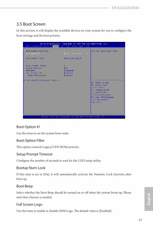
3.5 Boot ScreenIn this section, it will display the available devices on your system for you to configure the boot settings and the boot priority.
Boot Option #1
Use this item to set the system boot order.
Boot Option Filter
This option controls Legacy/UEFI ROMs priority.
Setup Prompt Timeout
Configure the number of seconds to wait for the UEFI setup utility.
Bootup Num-Lock
If this item is set to [On], it will automatically activate the Numeric Lock function after boot-up.
Boot Beep
Select whether the Boot Beep should be turned on or off when the system boots up. Please note that a buzzer is needed.
Full Screen Logo
Use this item to enable or disable OEM Logo. The default value is [Enabled].

68 69
English
AddOn ROM Display
Use this option to adjust AddOn ROM Display. If you enable the option “Full Screen Logo”but you want to see the AddOn ROM information when the system boots, please select[Enabled]. Configuration options: [Enabled] and [Disabled]. The default value is [Enabled].

EP2C622D16NM
68 69
Engl
ish
3.5.1 CSM Parameters
CSM
Enable to launch the Compatibility Support Module. Please do not disable unless you’re running a WHCK test. If you are using Windows Server 2012 R2 or later ver-sions 64-bit UEFI and all of your devices support UEFI, you may also disable CSM for faster boot speed.
Launch Video OpROM Policy
Select UEFI only to run those that support UEFI option ROM only. Select Legacy only to run those that support legacy option ROM only. Select Do not launch to not execute both legacy and UEFI option ROM.
MEZZ1 Slot OpROM
Use this item to select slot storage and Network Option ROM policy. In Auto option, the default is Disabled with NVMe device, but it is Legacy with other devices. (This item can't select Video Option ROM policy.)
MEZZ2 Slot OpROM
Use this item to select slot storage and Network Option ROM policy. In Auto option, the default is Disabled with NVMe device, but it is Legacy with other devices. (This item can't select Video Option ROM policy.)

70 71
English
PCIE6 Slot OpROM
Use this item to select slot storage and Network Option ROM policy. In Auto option, the default is Disabled with NVMe device, but it is Legacy with other devices. (This item can't select Video Option ROM policy.)
PCIE7 Slot OpROM
Use this item to select slot storage and Network Option ROM policy. In Auto option, the default is Disabled with NVMe device, but it is Legacy with other devices. (This item can't select Video Option ROM policy.)
OCU1 Slot OpROM
Use this item to select slot storage and Network Option ROM policy. In Auto option, the default is Disabled with NVMe device, but it is Legacy with other devices. (This item can't select Video Option ROM policy.)
OCU2 Slot OpROM
Use this item to select slot storage and Network Option ROM policy. In Auto option, the default is Disabled with NVMe device, but it is Legacy with other devices. (This item can't select Video Option ROM policy.)
M2_1 Slot OpROM
Use this item to select slot storage and Network Option ROM policy. In Auto option, the default is Disabled with NVMe device, but it is Legacy with other devices. (This item can't select Video Option ROM policy.)

EP2C622D16NM
70 71
Engl
ish
3.6 Event Logs
Change Smbios Event Log Settings
This allows you to configure the Smbios Event Log Settings.
When entering the item, you will see the followings:
Smbios Event LogUse this item to enable or disable all features of the SMBIOS Event Logging during system boot.
Erase Event LogThe options include [No], [Yes, Next reset] and [Yes, Every reset]. If Yes is selected, all logged events will be erased.
When Log is FullUse this item to choose options for reactions to a full Smbios Event Log. The options include [Do Nothing] and [Erase Immediately].
Log System Boot EventChoose option to enable/disable logging of System boot event.
MECI (Multiple Event Count Increment)Use this item to enter the increment value for the multiple event counter. The valid range is from 1 to 255.
METW (Multiple Event Time Window)Use this item to specify the number of minutes which must pass between duplicate log

72 73
English
entries which utilize a multiple-event counter. The value ranges from 0 to 99 minutes.
View Smbios Event LogPress <Enter> to view the Smbios Event Log records.
All values changed here do not take effect until computer is restarted.

EP2C622D16NM
72 73
Engl
ish
3.7 Server Mgmt
Wait For BMC
Wait For BMC response for specified time out. In PILOTII, BMC starts at the same time when BIOS starts during AC power ON. It takes around 30 seconds to initialize Host to BMC interfaces.

74 75
English
3.7.1 System Event Log
SEL Components
Change this to enable ro disable all features of System Event Logging during boot.
Erase SEL
Use this to choose options for earsing SEL.
When SEL is Full
Use this to choose options for reactions to a full SEL.
Log EFI Status Codes
Use this item to disable the logging of EFI Status Codes or log only error code or only progress or both.

EP2C622D16NM
74 75
Engl
ish
When [DHCP] or [Static] is selected, do NOT modify the BMC network settings on the IPMI web page.
3.7.2 BMC Network Configuration
Lan Channel (Failover)
Manual Setting IPMI LAN
If [No] is selected, the IP address is assigned by DHCP. If you prefer using a static IP address, toggle to [Yes], and the changes take effect after the system reboots. The default value is [No].
Configuration Address Source
Select to configure BMC network parameters statically or dynamically(by BIOS or BMC).Configuration options: [Static] and [DHCP].
Static: Manually enter the IP Address, Subnet Mask and Gateway Address in the BIOS for BMC LAN channel configuration.DHCP: IP address, Subnet Mask and Gateway Address are automatically assigned by the network's DHCP server.
76 77
English
The default login information for the IPMI web interface is: Username: admin Password: admin
For more instructions on how to set up remote control environment and use the IPMI man-agement platform, please refer to the IPMI Configuration User Guide or go to the Support website at: http://www.asrockrack.com/support/ipmi.asp

EP2C622D16NM
76 77
Engl
ish
3.8 Exit Screen
Save Changes and Exit
When you select this option, the following message “Save configuration changes and exit setup?” will pop-out. Press <F10> key or select [Yes] to save the changes and exit the UEFI SETUP UTILITY.
Discard Changes and Exit
When you select this option, the following message “Discard changes and exit setup?” will pop-out. Press <ESC> key or select [Yes] to exit the UEFI SETUP UTILITY without saving any changes.
Discard Changes
When you select this option, the following message “Discard changes?” will pop-out. Press <F7> key or select [Yes] to discard all changes.
Load UEFI Defaults
Load UEFI default values for all the setup questions. F9 key can be used for this operation.
Boot Override
These items displays the available devices. Select an item to start booting from the selected device.
78 79
English
Chapter 4 Software Support
4.1 Install Operating System This motherboard supports various Microsoft® Windows® Server 2012 / 2012 R2 / Linux compliant. Because motherboard settings and hardware options vary, use the setup procedures in this chapter for general reference only. Refer to your OS documentation for more information.
*Please download the Intel® SATA Floppy Image driver from the ASRock Rack’s website (www.asrockrack.com)
to your USB drive or simply install the SATA driver from the Support CD while installing OS in SATA RAID mode.
4.2 Support CD InformationThe Support CD that came with the motherboard contains necessary drivers and useful utilities that enhance the motherboard’s features.
4.2.1 Running The Support CD To begin using the support CD, insert the CD into your CD-ROM drive. The CD automatically displays the Main Menu if “AUTORUN” is enabled in your computer. If the Main Menu does not appear automatically, locate and double click on the file “ASRSetup.exe” from the root folder in the Support CD to display the menu.
4.2.2 Drivers MenuThe Drivers Menu shows the available device’s drivers if the system detects installed devices. Please install the necessary drivers to activate the devices.
4.2.3 Utilities MenuThe Utilities Menu shows the application softwares that the motherboard supports. Click on a specific item then follow the installation wizard to install it.
4.2.4 Contact InformationIf you need to contact ASRock Rack or want to know more about ASRock Rack, welcome to visit ASRock Rack’s website at http://www.ASRockRack.com; or you may contact your dealer for further information.

EP2C622D16NM
78 79
Engl
ish
Chapter 5 Troubleshooting
5.1 Troubleshooting ProceduresFollow the procedures below to troubleshoot your system.
1. Disconnect the power cable and check whether the PWR LED is off.2. Unplug all cables, connectors and remove all add-on cards from the motherboard.
Make sure that the jumpers are set to default settings.3. Confirm that there are no short circuits between the motherboard and the chassis.4. Install a CPU and fan on the motherboard, then connect the chassis speaker and power
LED.
If there is no power...1. Confirm that there are no short circuits between the motherboard and the chassis.2. Make sure that the jumpers are set to default settings.3. Check the settings of the 115V/230V switch on the power supply.4. Verify if the battery on the motherboard provides ~3VDC. Install a new battery if it
does not.
If there is no video...1. Try replugging the monitor cables and power cord.2. Check for memory errors.
If there are memory errors...1. Verify that the DIMM modules are properly seated in the slots.2. Use recommended DDR4 2133 R-DIMMs.3. If you have installed more than one DIMM modules, they should be identical with the
same brand, speed, size and chip-type.4. Try inserting different DIMM modules into different slots to identify faulty ones.5. Check the settings of the 115V/230V switch on the power supply.
Always unplug the power cord before adding, removing or changing any hardware com-ponents. Failure to do so may cause physical injuries to you and damages to motherboard components.

80 81
English
Unable to save system setup configurations...1. Verify if the battery on the motherboard provides ~3VDC. Install a new battery if it
does not.2. Confirm whether your power supply provides adaquate and stable power.
Other problems...1. Try searching keywords related to your problem on ASRock Rack’s FAQ page:
http://www.asrockrack.com/support

EP2C622D16NM
80 81
Engl
ish
5.2 Technical Support ProceduresIf you have tried the troubleshooting procedures mentioned above and the problems are still unsolved, please contact ASRock Rack’s technical support with the following information:
1. Your contact information2. Model name, BIOS version and problem type.3. System configuration.4. Problem description.
You may contact ASRock Rack’s technical support at:http://www.asrockrack.com/support/tsd.asp
5.3 Returning Merchandise for ServiceFor warranty service, the receipt or a copy of your invoice marked with the date of purchase is required. By calling your vendor or going to our RMA website (http://event. asrockrack.com/tsd.asp) you may obtain a Returned Merchandise Authorization (RMA) number.The RMA number should be displayed on the outside of the shipping carton which is mailed prepaid or hand-carried when you return the motherboard to the manufacturer. Shipping and handling charges will be applied for all orders that must be mailed when service is complete.
This warranty does not cover damages incurred in shipping or from failure due to alteration, misuse, abuse or improper maintenance of products.
Contact your distributor first for any product related problems during the warranty period.