Embed Size (px)
Citation preview
Schleibinger Geräte
User Manual
CDF-Freeze-Thaw-Testing Machine
Schleibinger Geräte Teubert u. Greim GmbHGewerbestraße 4, 84428 Buchbach
Telefon (0 80 86) 9 40 10, Telefax (0 80 869) 9 40 14Mobil (01 71) 7 32 16 70, (0172) 8 999 196
www. schleibinger.com , [email protected]
Contents 1 INTRODUCTION...............................................3
2 INSTALLATION AND SECURITY HINTS........4
2.1 SETUP OF THE MACHINE........................................4 2.2 INTERNET CONNECTION..........................................5
2.2.1 Chiptool...................................................6 2.2.2 CompactFlash Card................................7
2.3 PROTECTION SWITCHES AND PERSONAL SAFETY.........7 2.4 REPAIR AND MAINTENANCE.....................................8
3 PRINCIPLES OF OPERATION........................9
3.1 GENERAL............................................................9 3.2 SYSTEM OPERATION..............................................9 3.3 MECHANICAL CONSTRUCTION.................................10
3.3.1 Testing tub.............................................11 3.3.2 Circulation Unit......................................11 3.3.3 Freeze Resistance................................13
3.4 CUBE TEST.......................................................14 3.5 KEY SWITCH.....................................................16 3.6 TRANSPORT OF THE CDF MACHINE.......................16 3.7 EMPTY THE COOLANT LIQUID................................16 3.8 COOLING WATER CONNECTION (OPTION).................17
4 HANDLING THE CONTROLLER...................18
4.1 INTRODUCTION....................................................18 4.2 KEYBOARD AND DISPLAY......................................18 4.3 HANDLING.........................................................18
4.3.1 Start.......................................................18 4.3.2 Status....................................................19 4.3.3 Cycle Time............................................21
4.4 SETUP..............................................................21 4.4.1 Target Value..........................................22 4.4.2 Profile Input...........................................22 4.4.3 Display..................................................24 4.4.4 Clock.....................................................25
4.5 SYSTEM MENU...................................................26 4.5.1 Manual..................................................26 4.5.2 DA Calibration.......................................27 4.5.3 Controller...............................................28 4.5.4 Probes...................................................31 4.5.5 RAM Reset............................................32 4.5.6 Misc.......................................................32
5 TECHNICAL DATA .......................................33
6 SERVICE HINTS.............................................34
6.1 MAINTENANCE CONTROLLER..................................34 6.2 VALUES FOR THE SECURITY DEVICES......................34 6.3 HELP YOURSELF................................................35
7 SCHEMATIC DRAWINGS .............................38
7.1 REFRIGERANT SCHEMATIC.....................................38 7.2 FUSES..............................................................39
8 INDEX.............................................................40
CDF-Freeze Thaw- Testing Machine page 2
1 Introduction
Congratulations: You buy a sophisticated measurement system for testing the freeze thaw resistance of concrete. This machine equipped, with the latest generation of micro-controller and Internet technology will satisfy you now and also in the future. This machine is engineered according to the latest standards of security and environmental protection.
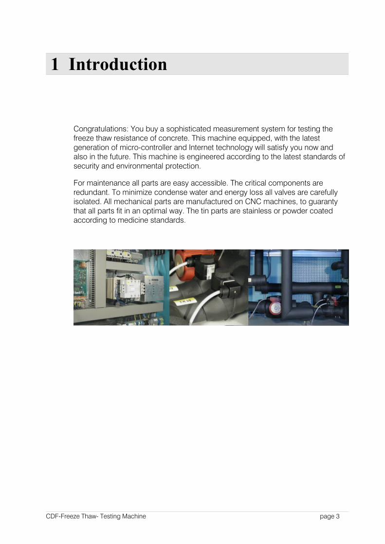
For maintenance all parts are easy accessible. The critical components are redundant. To minimize condense water and energy loss all valves are carefully isolated. All mechanical parts are manufactured on CNC machines, to guaranty that all parts fit in an optimal way. The tin parts are stainless or powder coated according to medicine standards.
CDF-Freeze Thaw- Testing Machine page 3
2 Installation and Security Hints
2.1 Setup of the Machine
The ground floor should withstand a pressure of 300 kg/m². Air cooled machines should be installed in rooms not smaller then 200 m³.. This rooms should have a good air exchange, to keep the room temperature below 28°C. Also for water
cooled machines , according to DIN EN 378-1 the room volume should be at least 8 m³ , if with leak cooling gas comes into the atmosphere.
If the distance between the backside of the machine and the wall is below 50cm, you should change the perforated cover to the front side to ensure a free circulation for the air (for air cooled machines)
Be sure that the machine stands horizontal. Please check this by a level at the cooling bath. If necessary the machine may be setup by the four adjustable feet. The horizontal deviation should be not higher then 1-2 mm/m.
This machine is constructed according to DIN EN 378-1class A. This means it is allowed to run this machine in a room where people are sleeping, disabled persons are working, or a lot of not instructed people are present. So there are no special requirements in the training of the people working with, or nearby the machine.
As cooling liquid a mix of 45 % tap water and 55 % glycol coolant is used. This according to the European water protection standard level 0 . There are no special requirements for environmental or water protection.
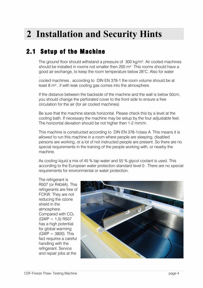
The refrigerant is R507 (or R404A). This refrigerants are free of FCKW. They are not reducing the ozone shield in the atmosphere. Compared with CO2
(GWP = 1,0) R507 has a high potential for global warming (GWP = 3800). This fact requires a careful handling with the refrigerant. Service and repair jobs at the
CDF-Freeze Thaw- Testing Machine page 4
0,4m 0,4 m
0,5 m
Kabe llänge3 m
Schleibinger Geräte0,8m
2,25m
Opti onalKüh lwasserVor- /Rücklauf
Lufteinlassnicht verstellen
at the cooling machine are allowed only for well trained and special educated persons. Pleas contact our service center for further questions.
The lubricant of the cooling machine has not be changed during the lifetime of the machine. The oil is classified at water dangerous class =1. There are no special oil protection requirements necessary, because the machine automatically stopp if there is a leakage in system.
The CDF/CIF-machine has a mains connection with a 3x32A/400V/50Hz CEE connector. As circuit protection 3x32A are necessary.
The environmental conditions should be at 10 to 28 °C at maximum 65 % relative humidity. If the humidity is higher there may be more condense water at some machine parts. Below 10°C s special winter-controller should be ordered with the machine. For temperatures over 28°C an additional water cooling is necessary.
Opening the lid of the cooling bath is only allowed when the bath temperature is near the room temperature. We strongly recommend water-proof isolation protection gloves. Contact to the cooling bath may cause freezing the skin, fingers, or the hand.
2.2 Internet Connection
The CDF testing machine from Schleibinger is equipped (option) with an internet interface. So you may easy integrate the machine in your laboratory network or in the world-wide-net. You can contact the CDF machine as easy as any other web-site. Also you may use the telnet or FTP service.
The WEB server integrated in the CDF machine displays the the temperature data as well as the actual temperature and some status information.
To contact the CDF machine input the IP address of the CDF machine in your web-browser software. For example :
http://192.168.1.40
The CDF machine need a fix IP address.
CDF-Freeze Thaw- Testing Machine page 5
2.2.1 Chiptool
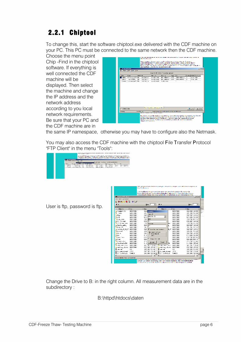
To change this, start the software chiptool.exe delivered with the CDF machine on your PC. This PC must be connected to the same network then the CDF machine. Choose the menu point Chip -Find in the chiptool software. If everything is well connected the CDF machine will be displayed. Then select the machine and change the IP address and the network address according to you local network requirements. Be sure that your PC and the CDF machine are in the same IP namespace, otherwise you may have to configure also the Netmask.
You may also access the CDF machine with the chiptool File Transfer Protocol "FTP Client" in the menu "Tools":
User is ftp, password is ftp.
Change the Drive to B: in the right column. All measurement data are in the subdirectory :
B:\httpd\htdocs\daten
CDF-Freeze Thaw- Testing Machine page 6
All program files in:
B:\httpd\cgi-bin.
For advanced users: As super user you may also have an access to the machine via Telnet:
User is tel, password is tel.
In the telnet window a command line terminal will be opened. Here you may use most of the usual DAS commands. Press help Enter if you are in doubt. Give the command closetelnet to close the connection.
2.2.2 CompactFlash Card
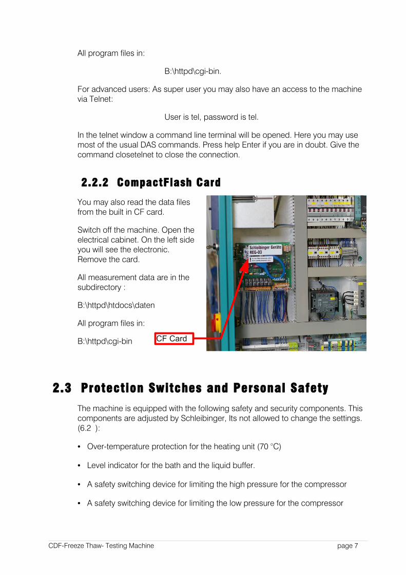
You may also read the data files from the built in CF card.
Switch off the machine. Open the electrical cabinet. On the left side you will see the electronic. Remove the card.
All measurement data are in the subdirectory :
B:\httpd\htdocs\daten
All program files in:
B:\httpd\cgi-bin
2.3 Protection Switches and Personal Safety
The machine is equipped with the following safety and security components. This components are adjusted by Schleibinger, Its not allowed to change the settings. (6.2 ):
• Over-temperature protection for the heating unit (70 °C)
• Level indicator for the bath and the liquid buffer.
• A safety switching device for limiting the high pressure for the compressor
• A safety switching device for limiting the low pressure for the compressor
CDF-Freeze Thaw- Testing Machine page 7
CF Card
Changing the setup of the security devices is not allowed. Any manipulation will lead to a total warranty loss!
Pleas follow carefully all standards and laws for personal protection. Also follow the DIN EN 378-1 and DIN EN 378-2 standards.
The owner of the machine has to supply personal protection equipment, specially security gloves and security eye glasses for all people working with the machine.
2.4 Repair and Maintenance
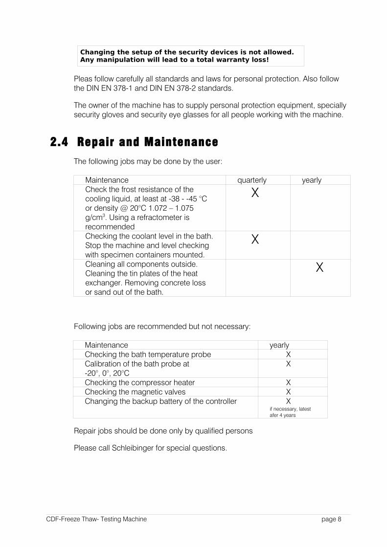
The following jobs may be done by the user:
Maintenance quarterly yearlyCheck the frost resistance of the cooling liquid, at least at -38 - -45 °C or density @ 20°C 1.072 – 1.075 g/cm3. Using a refractometer is recommended
X
Checking the coolant level in the bath. Stop the machine and level checking with specimen containers mounted.
X
Cleaning all components outside. Cleaning the tin plates of the heat exchanger. Removing concrete loss or sand out of the bath.
X
Following jobs are recommended but not necessary:
Maintenance yearlyChecking the bath temperature probe XCalibration of the bath probe at -20°, 0°, 20°C
X
Checking the compressor heater XChecking the magnetic valves XChanging the backup battery of the controller X
if necessary, latest afer 4 years
Repair jobs should be done only by qualified persons
Please call Schleibinger for special questions.
CDF-Freeze Thaw- Testing Machine page 8
3 Principles of Operation
3.1 General
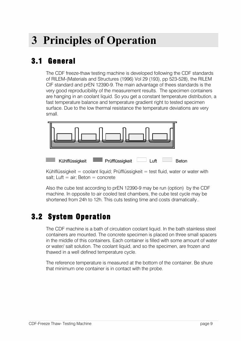
The CDF freeze-thaw testing machine is developed following the CDF standards of RILEM-(Materials and Structures (1996) Vol 29 (193), pp 523-528), the RILEM CIF standard and prEN 12390-9. The main advantage of thees standards is the very good reproducibility of the measurement results. The specimen containers are hanging in an coolant liquid. So you get a constant temperature distribution, a fast temperature balance and temperature gradient right to tested specimen surface. Due to the low thermal resistance the temperature deviations are very small.
BetonLuftPrüfflüssigkeitKühlflüssigkeit
Kühlflüssigkeit = coolant liquid; Prüfflüssigkeit = test fluid, water or water with salt; Luft = air; Beton = concrete
Also the cube test according to prEN 12390-9 may be run (option) by the CDF machine. In opposite to air cooled test chambers, the cube test cycle may be shortened from 24h to 12h. This cuts testing time and costs dramatically..
3.2 System Operation
The CDF machine is a bath of circulation coolant liquid. In the bath stainless steel containers are mounted. The concrete specimen is placed on three small spacers in the middle of this containers. Each container is filled with some amount of water or water/ salt solution. The coolant liquid, and so the specimen, are frozen and thawed in a well defined temperature cycle.
The reference temperature is measured at the bottom of the container. Be shure that minimum one container is in contact with the probe.
CDF-Freeze Thaw- Testing Machine page 9
Z e mpe ra turz y k lus
- 2 0
- 1 5
- 1 0
- 5
0
5
1 0
1 5
2 0
0 1 2 3 4 5 6 7 8 9 1 0 1 1 1 2
T
e
m
p
e
r
a
t
u
r
h
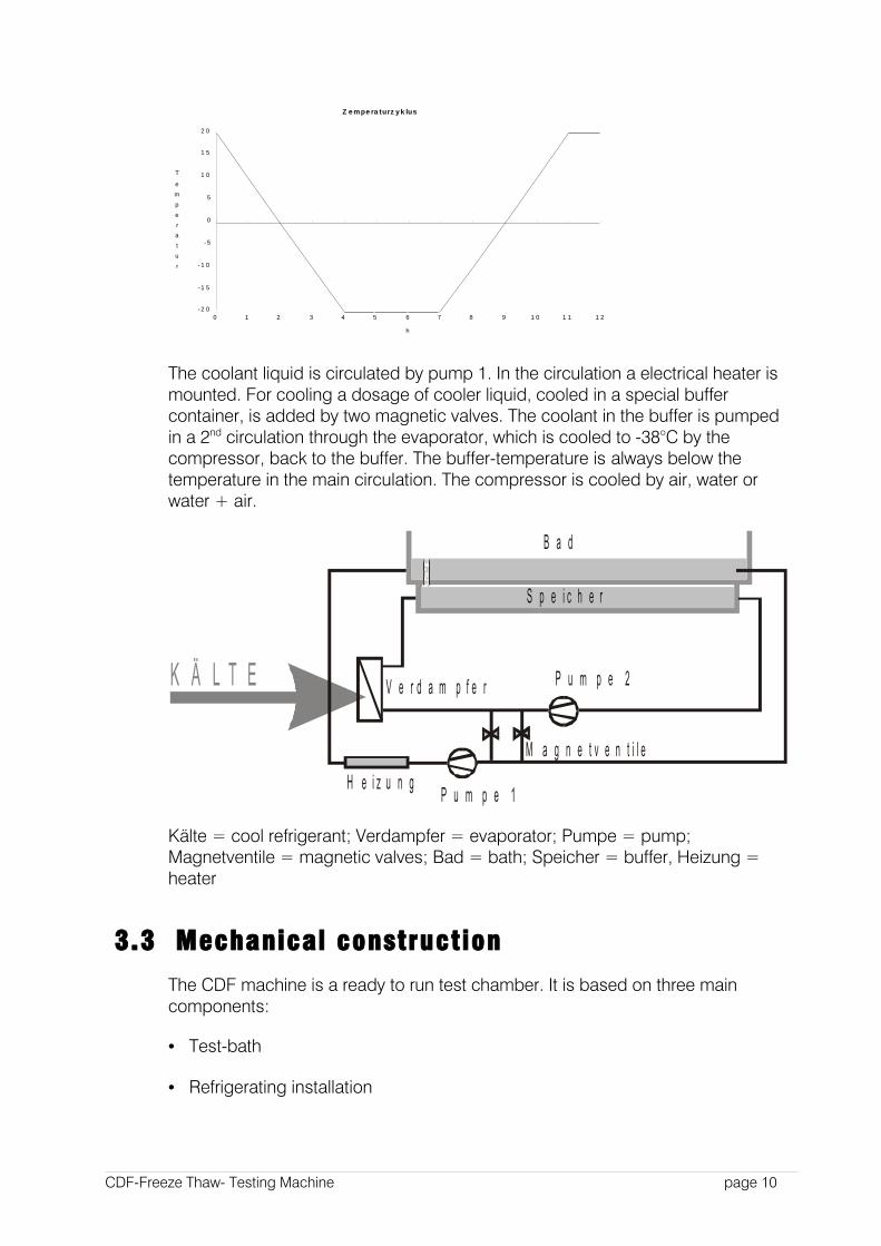
The coolant liquid is circulated by pump 1. In the circulation a electrical heater is mounted. For cooling a dosage of cooler liquid, cooled in a special buffer container, is added by two magnetic valves. The coolant in the buffer is pumped in a 2nd circulation through the evaporator, which is cooled to -38°C by the compressor, back to the buffer. The buffer-temperature is always below the temperature in the main circulation. The compressor is cooled by air, water or water + air.
K Ä L T E
B a d
S p e i c h e r
P u m p e 2
P u m p e 1H e i z u n g
V e r d a m p f e r
M a g n e t v e n t i l e
Kälte = cool refrigerant; Verdampfer = evaporator; Pumpe = pump; Magnetventile = magnetic valves; Bad = bath; Speicher = buffer, Heizung = heater
3.3 Mechanical construction
The CDF machine is a ready to run test chamber. It is based on three main components:
• Test-bath
• Refrigerating installation
CDF-Freeze Thaw- Testing Machine page 10
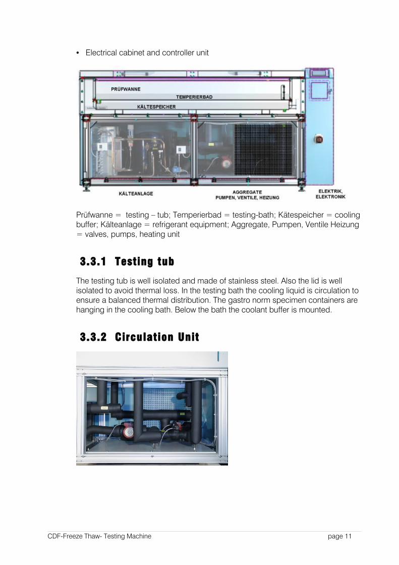
• Electrical cabinet and controller unit
Prüfwanne = testing – tub; Temperierbad = testing-bath; Kätespeicher = cooling buffer; Kälteanlage = refrigerant equipment; Aggregate, Pumpen, Ventile Heizung = valves, pumps, heating unit
3.3.1 Testing tub
The testing tub is well isolated and made of stainless steel. Also the lid is well isolated to avoid thermal loss. In the testing bath the cooling liquid is circulation to ensure a balanced thermal distribution. The gastro norm specimen containers are hanging in the cooling bath. Below the bath the coolant buffer is mounted.
3.3.2 Circulation Unit
CDF-Freeze Thaw- Testing Machine page 11
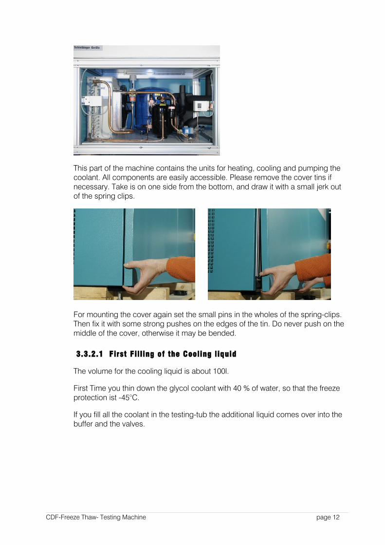
This part of the machine contains the units for heating, cooling and pumping the coolant. All components are easily accessible. Please remove the cover tins if necessary. Take is on one side from the bottom, and draw it with a small jerk out of the spring clips.
For mounting the cover again set the small pins in the wholes of the spring-clips. Then fix it with some strong pushes on the edges of the tin. Do never push on the middle of the cover, otherwise it may be bended.
3.3.2.1 First Fil l ing of the Cooling liquid
The volume for the cooling liquid is about 100l.
First Time you thin down the glycol coolant with 40 % of water, so that the freeze protection ist -45°C.
If you fill all the coolant in the testing-tub the additional liquid comes over into the buffer and the valves.
CDF-Freeze Thaw- Testing Machine page 12
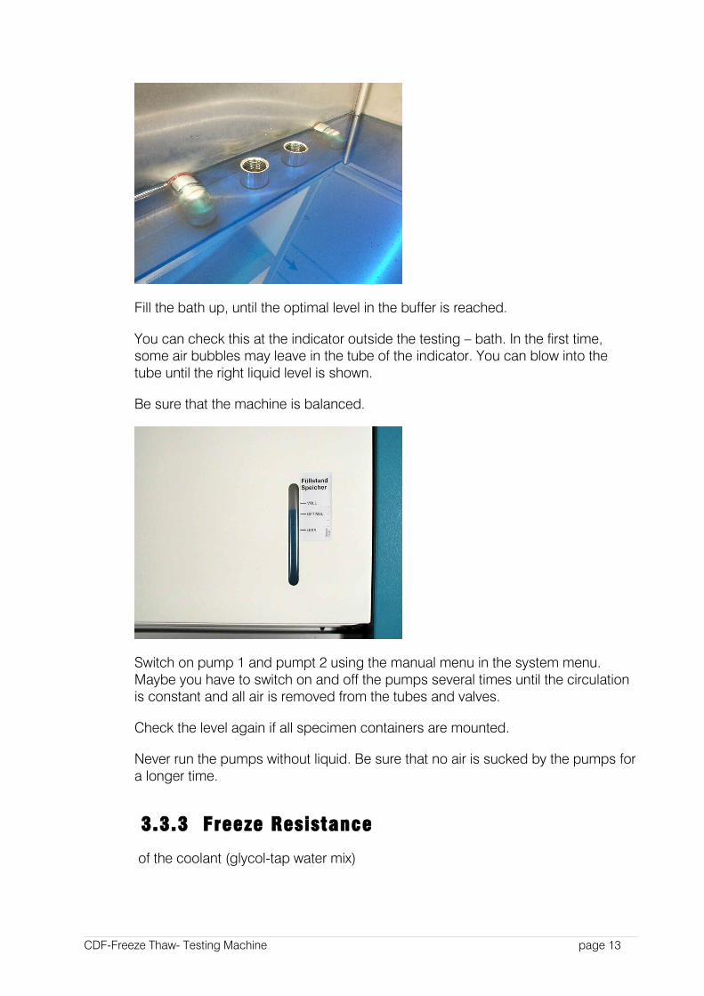
Fill the bath up, until the optimal level in the buffer is reached.
You can check this at the indicator outside the testing – bath. In the first time, some air bubbles may leave in the tube of the indicator. You can blow into the tube until the right liquid level is shown.
Be sure that the machine is balanced.
Switch on pump 1 and pumpt 2 using the manual menu in the system menu. Maybe you have to switch on and off the pumps several times until the circulation is constant and all air is removed from the tubes and valves.
Check the level again if all specimen containers are mounted.
Never run the pumps without liquid. Be sure that no air is sucked by the pumps for a longer time.
3.3.3 Freeze Resistance
of the coolant (glycol-tap water mix)
CDF-Freeze Thaw- Testing Machine page 13
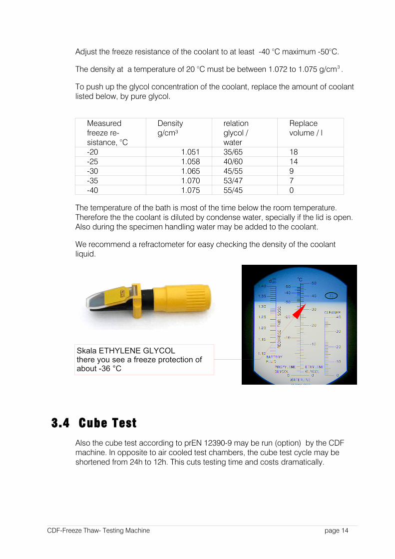
Adjust the freeze resistance of the coolant to at least -40 °C maximum -50°C.
The density at a temperature of 20 °C must be between 1.072 to 1.075 g/cm3 .
To push up the glycol concentration of the coolant, replace the amount of coolant listed below, by pure glycol.
Measured freeze re-sistance, °C
Density g/cm³
relationglycol / water
Replace volume / l
-20 1.051 35/65 18 -25 1.058 40/60 14 -30 1.065 45/55 9-35 1.070 53/47 7-40 1.075 55/45 0
The temperature of the bath is most of the time below the room temperature. Therefore the the coolant is diluted by condense water, specially if the lid is open. Also during the specimen handling water may be added to the coolant.
We recommend a refractometer for easy checking the density of the coolant liquid.
3.4 Cube Test
Also the cube test according to prEN 12390-9 may be run (option) by the CDF machine. In opposite to air cooled test chambers, the cube test cycle may be shortened from 24h to 12h. This cuts testing time and costs dramatically.
CDF-Freeze Thaw- Testing Machine page 14
Skala ETHYLENE GLYCOLthere you see a freeze protection ofabout -36 °C

To change over to the cube test, a higher liquid level in the bath is recommended. To get this, an additional outlet can be fixed.
Please don´t forget to put the filter over the outlet.
Put in most of the specimen containers and fill in additional coolant liquid.
Check the liquid level at the level indicator right in front of the instrument.
CDF-Freeze Thaw- Testing Machine page 15
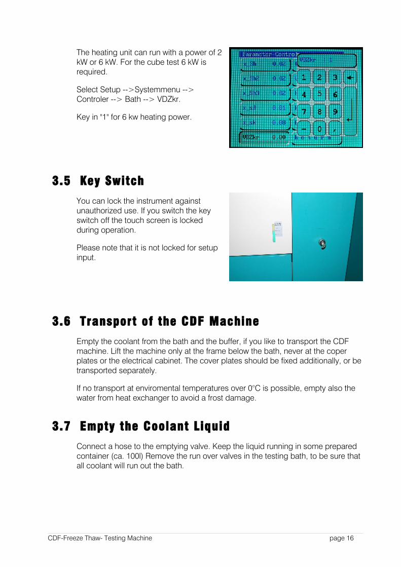
The heating unit can run with a power of 2 kW or 6 kW. For the cube test 6 kW is required.
Select Setup -->Systemmenu --> Controler --> Bath --> VDZkr.
Key in "1" for 6 kw heating power.
3.5 Key Switch
You can lock the instrument against unauthorized use. If you switch the key switch off the touch screen is locked during operation.
Please note that it is not locked for setup input.
3.6 Transport of the CDF Machine
Empty the coolant from the bath and the buffer, if you like to transport the CDF machine. Lift the machine only at the frame below the bath, never at the coper plates or the electrical cabinet. The cover plates should be fixed additionally, or be transported separately.
If no transport at enviromental temperatures over 0°C is possible, empty also the water from heat exchanger to avoid a frost damage.
3.7 Empty the Coolant Liquid
Connect a hose to the emptying valve. Keep the liquid running in some prepared container (ca. 100l) Remove the run over valves in the testing bath, to be sure that all coolant will run out the bath.
CDF-Freeze Thaw- Testing Machine page 16
3.8 Cooling Water Connection (option)
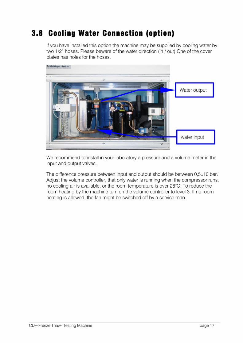
If you have installed this option the machine may be supplied by cooling water by two 1/2“ hoses. Please beware of the water direction (in / out) One of the cover plates has holes for the hoses.
We recommend to install in your laboratory a pressure and a volume meter in the input and output valves.
The difference pressure between input and output should be between 0,5..10 bar. Adjust the volume controller, that only water is running when the compressor runs, no cooling air is available, or the room temperature is over 28°C. To reduce the room heating by the machine turn on the volume controller to level 3. If no room heating is allowed, the fan might be switched off by a service man.
CDF-Freeze Thaw- Testing Machine page 17
water input
Water output
4 Handling the Controller
4.1 Introduction
This part of the user manual describes all features you may handle by the touch screen of the controller. The controller is mounted on the left side of the electrical cabinet.
4.2 Keyboard and Display
The user interface is a modern colored touchscreen.
If you setup some parameters virtual buttons are displayed on the screen. During the test run, you may stop the machine by touching any place on the screen (if the keyboard key-switch is on)
4.3 Handling
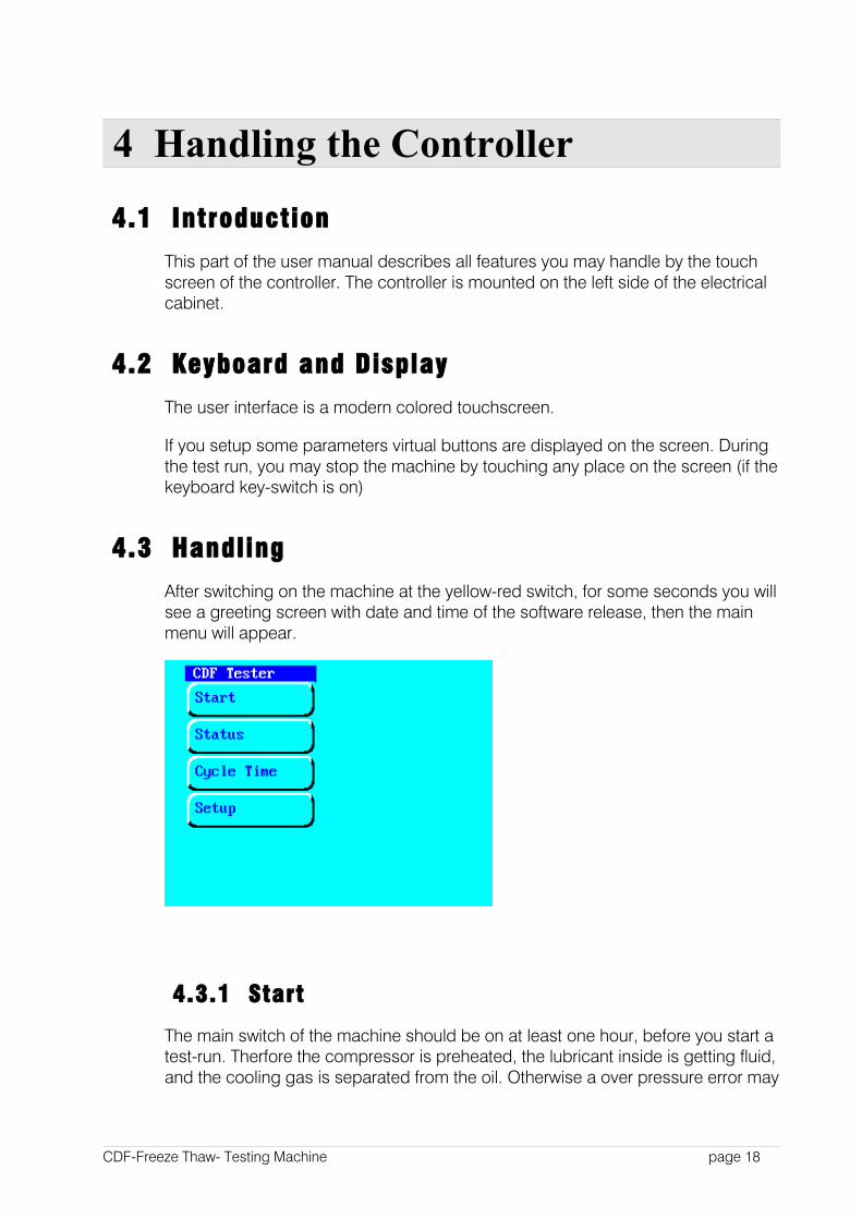
After switching on the machine at the yellow-red switch, for some seconds you will see a greeting screen with date and time of the software release, then the main menu will appear.
4.3.1 Start
The main switch of the machine should be on at least one hour, before you start a test-run. Therfore the compressor is preheated, the lubricant inside is getting fluid, and the cooling gas is separated from the oil. Otherwise a over pressure error may
CDF-Freeze Thaw- Testing Machine page 18

occur and the machine will be automatically stopped again. If you are sure that the compressor is warm enough, you may cancel this warning by pressing Continue
The machine starts with defined cycle clock. The cycle time is battery back-upped when the machine was switched off. The cycle time may be set in the appropriate menu. With the CDF test 28 cycles a 24h are run. You may also activate other cycles. If the last cycle is over, the temperature will be kept constant at 20°C. So if you start a new test-run, you have to reset the number of cycles and the cycle time.
ATTENTION The machine is protected against automatic restart when the mains was off. For restart you have to press the start button.
If you want to restart automatically you may activate the automatic restart at System-Menu --> Div. --> Restart.
The temperature profile and the number of cycles may be reprogrammed in the System-Menu, Profile-Input. The CDF profile is activated by default.
4.3.2 Status
Status give an info of all machine units as well about all temperatures. The graphic of the last 24h temperatures will be implemented in the next software release.
CDF-Freeze Thaw- Testing Machine page 19
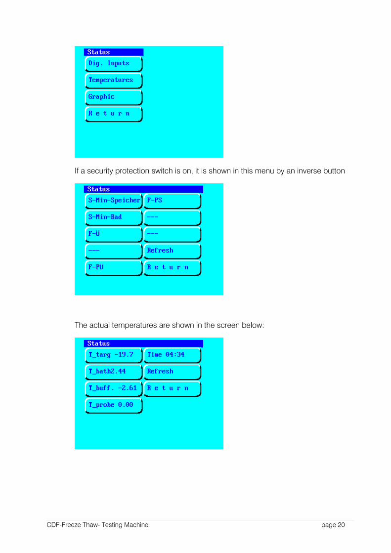
If a security protection switch is on, it is shown in this menu by an inverse button
The actual temperatures are shown in the screen below:
CDF-Freeze Thaw- Testing Machine page 20
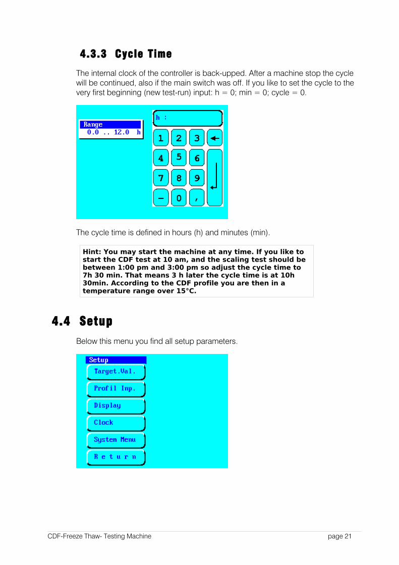
4.3.3 Cycle Time
The internal clock of the controller is back-upped. After a machine stop the cycle will be continued, also if the main switch was off. If you like to set the cycle to the very first beginning (new test-run) input: h = 0; min = 0; cycle = 0.
The cycle time is defined in hours (h) and minutes (min).
Hint: You may start the machine at any time. If you like to start the CDF test at 10 am, and the scaling test should be between 1:00 pm and 3:00 pm so adjust the cycle time to 7h 30 min. That means 3 h later the cycle time is at 10h 30min. According to the CDF profile you are then in a temperature range over 15°C.
4.4 Setup
Below this menu you find all setup parameters.
CDF-Freeze Thaw- Testing Machine page 21
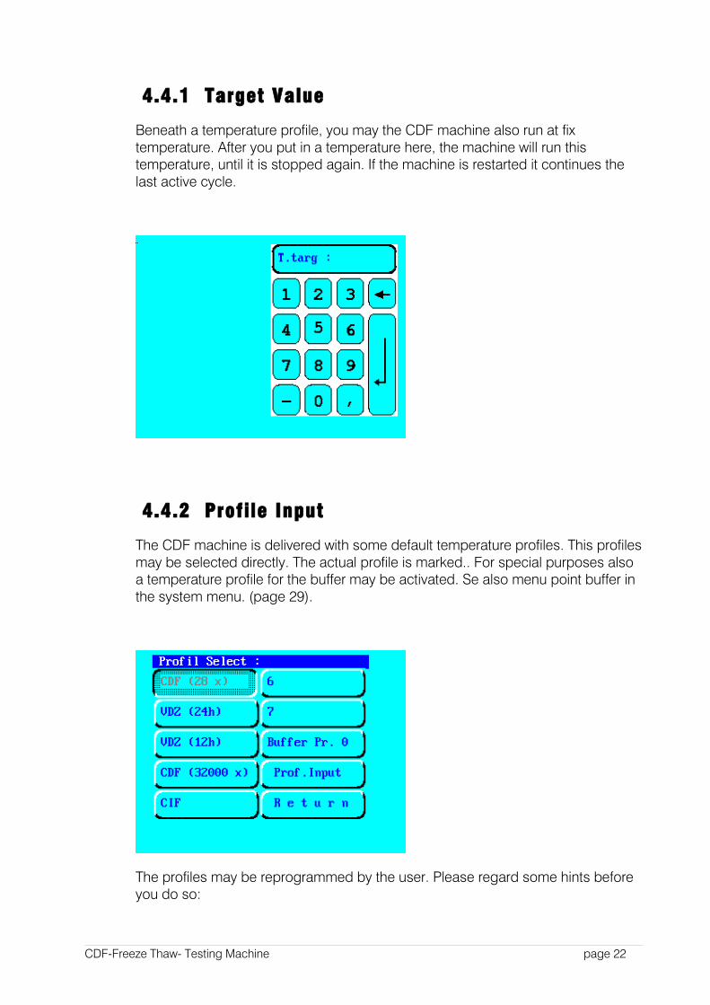
4.4.1 Target Value
Beneath a temperature profile, you may the CDF machine also run at fix temperature. After you put in a temperature here, the machine will run this temperature, until it is stopped again. If the machine is restarted it continues the last active cycle.
4.4.2 Profile Input
The CDF machine is delivered with some default temperature profiles. This profiles may be selected directly. The actual profile is marked.. For special purposes also a temperature profile for the buffer may be activated. Se also menu point buffer in the system menu. (page 29).
The profiles may be reprogrammed by the user. Please regard some hints before you do so:
CDF-Freeze Thaw- Testing Machine page 22
1. The control algorithm is optimized for the CDF test. Each modification may reduce the controlling quality. As a worst case the controller is no longer stable.
1. The refrigerant installation is also optimized for the CDF cycle. Avoid temperatures below -20°C.
1. The coolant liquid is getting very thick at temperatures below -25°C. It may freeze at temperatures below. Then the machine stops.
2. The pumps are specified for temperatures between –20 °C and +40 °C
HINT: Changing the temperature profiles maybe a misuse of the machine according to the warranty regulations. Please contact us before you define a new profile.
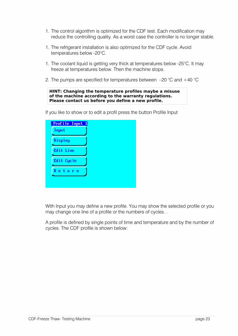
If you like to show or to edit a profil press the button Profile Input
With Input you may define a new profile. You may show the selected profile or you may change one line of a profile or the numbers of cycles. .
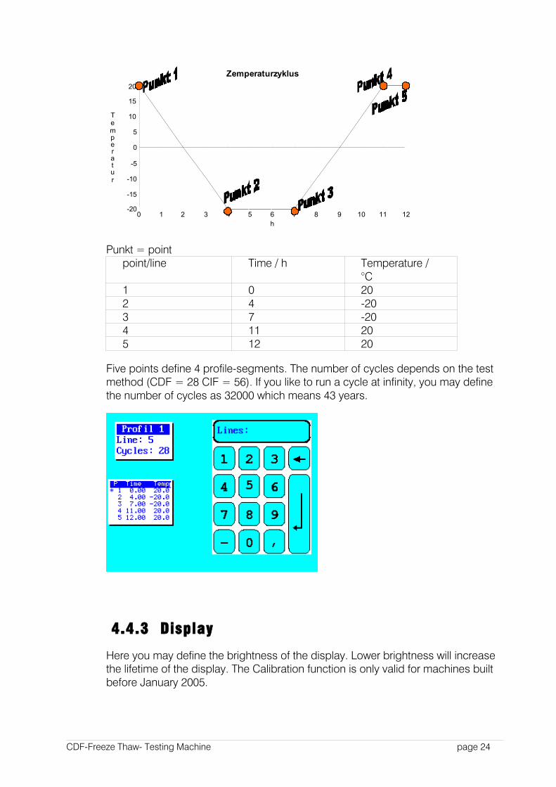
A profile is defined by single points of time and temperature and by the number of cycles. The CDF profile is shown below:
CDF-Freeze Thaw- Testing Machine page 23
Zemperaturzyklus
-20
-15
-10
-5
0
5
10
15
20
0 1 2 3 4 5 6 7 8 9 10 11 12
Temperatur
h
Punkt = point point/line Time / h Temperature /
°C1 0 202 4 -203 7 -204 11 205 12 20
Five points define 4 profile-segments. The number of cycles depends on the test method (CDF = 28 CIF = 56). If you like to run a cycle at infinity, you may define the number of cycles as 32000 which means 43 years.
4.4.3 Display
Here you may define the brightness of the display. Lower brightness will increase the lifetime of the display. The Calibration function is only valid for machines built before January 2005.
CDF-Freeze Thaw- Testing Machine page 24
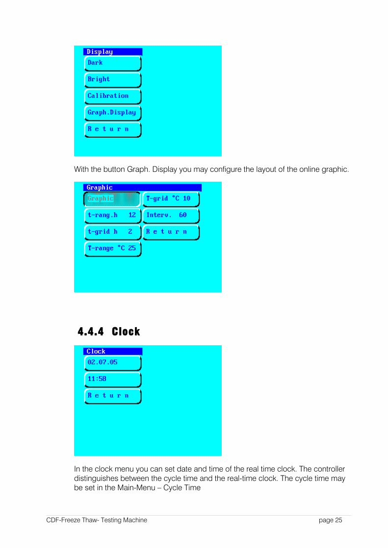
With the button Graph. Display you may configure the layout of the online graphic.
4.4.4 Clock
In the clock menu you can set date and time of the real time clock. The controller distinguishes between the cycle time and the real-time clock. The cycle time may be set in the Main-Menu – Cycle Time
CDF-Freeze Thaw- Testing Machine page 25
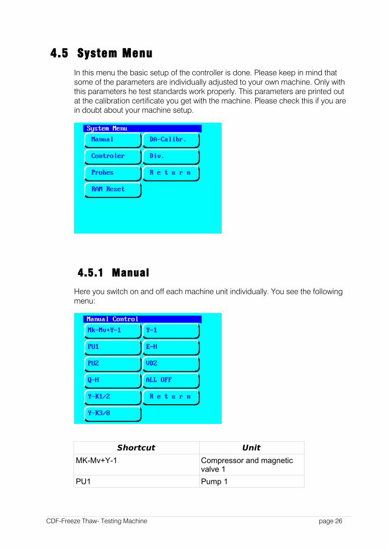
4.5 System Menu
In this menu the basic setup of the controller is done. Please keep in mind that some of the parameters are individually adjusted to your own machine. Only with this parameters he test standards work properly. This parameters are printed out at the calibration certificate you get with the machine. Please check this if you are in doubt about your machine setup.
4.5.1 Manual
Here you switch on and off each machine unit individually. You see the following menu:
Shortcut Unit
MK-Mv+Y-1 Compressor and magnetic valve 1
PU1 Pump 1
CDF-Freeze Thaw- Testing Machine page 26

Shortcut Unit
PU2 Pump 2
Q-H Relay Heating
Y-K1/2 Magnetic valve 1/2“
Y-K3/8 Magnetic valve 3/8“
Y-1 Magnetic valve for the refrigerant
E-H Solid state relay for the heating unit
VDZ Relay for the cube test heating unit (option)
Attention: If you switch on the compressor in the manual menu, some of the security switches may be deactivated. Do never switch on the heating unit when the pump 1 is off. The heating unit is only on when E-H and Q-H are on. Don't use this menu if you are not sure about all machine units. Misusing of the units may destroy them. Please call our service team before you use this functions.
4.5.2 DA Calibration
This function (DA Output) is for calibrating the line recorder (option). A fix voltage is sent on each channel to the recorder.
The following voltages are applied at the 25pin D-Sub connector:
CDF-Freeze Thaw- Testing Machine page 27
Kanal Pin1 Temperature bath 92 Target temperature 103 10 times the
difference between channel 1 and channel 2
23
4 Buffer temperature 24GND 7
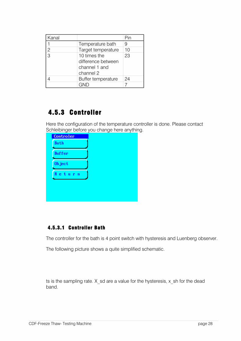
4.5.3 Controller
Here the configuration of the temperature controller is done. Please contact Schleibinger before you change here anything.
4.5.3.1 Controller Bath
The controller for the bath is 4 point switch with hysteresis and Luenberg observer.
The following picture shows a quite simplified schematic.
ts is the sampling rate. X_sd are a value for the hysteresis, x_sh for the dead band.
CDF-Freeze Thaw- Testing Machine page 28
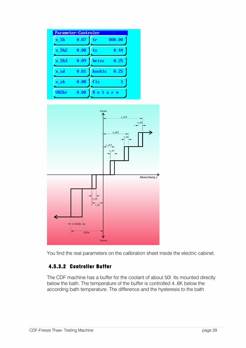
You find the real parameters on the calibration sheet inside the electric cabinet.
4.5.3.2 Controller Buffer
The CDF machine has a buffer for the coolant of about 50l. Its mounted directly below the bath. The temperature of the buffer is controlled 4..6K below the according bath temperature. The difference and the hysteresis to the bath
CDF-Freeze Thaw- Testing Machine page 29
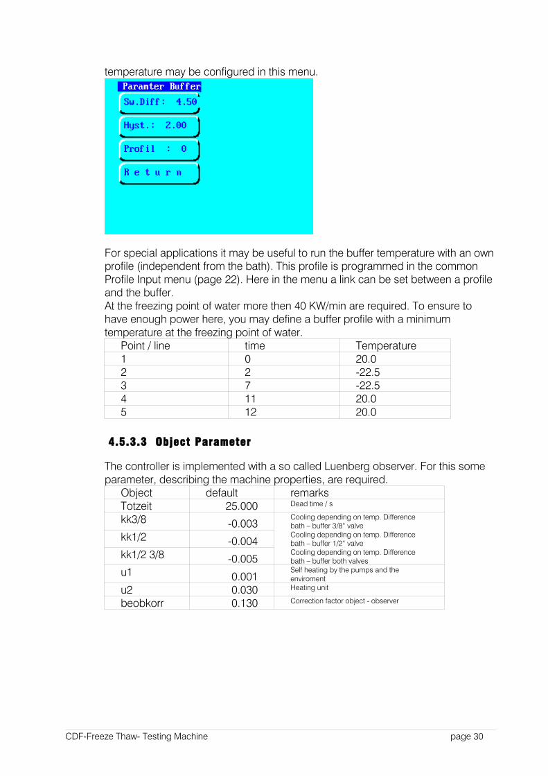
temperature may be configured in this menu.
For special applications it may be useful to run the buffer temperature with an own profile (independent from the bath). This profile is programmed in the common Profile Input menu (page 22). Here in the menu a link can be set between a profile and the buffer. At the freezing point of water more then 40 KW/min are required. To ensure to have enough power here, you may define a buffer profile with a minimum temperature at the freezing point of water.
Point / line time Temperature1 0 20.02 2 -22.53 7 -22.54 11 20.05 12 20.0
4.5.3.3 Object Parameter
The controller is implemented with a so called Luenberg observer. For this some parameter, describing the machine properties, are required.
Object default remarksTotzeit 25.000 Dead time / s
kk3/8 -0.003Cooling depending on temp. Difference bath – buffer 3/8“ valve
kk1/2 -0.004Cooling depending on temp. Difference bath – buffer 1/2“ valve
kk1/2 3/8 -0.005Cooling depending on temp. Difference bath – buffer both valves
u1 0.001Self heating by the pumps and the enviroment
u2 0.030 Heating unit
beobkorr 0.130 Correction factor object - observer
CDF-Freeze Thaw- Testing Machine page 30
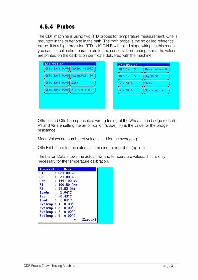
4.5.4 Probes
The CDF machine is using two RTD probes for temperature measurement. One is mounted in the buffer one in the bath. The bath probe is the so called reference probe. It is a high precision RTD 1/10 DIN B with blind slope wiring. In this menu you can set calibration parameters for the sensors. Don't change this. The values are printed on the calibration certificate delivered with the machine.
Offs1+ and Offs1-compensate a wrong tuning of the Wheatstone bridge (offset) . V1 and V2 are setting the amplification (slope). Ry is the value for the bridge resistance.
Mean Values are number of values used for the averaging.
Offs Ext1..4 are for the external semiconductor probes (option)
The button Data shows the actual raw and temperature values. This is only necessary for the temperature calibration.
CDF-Freeze Thaw- Testing Machine page 31
HINT: Use for calibration a mixed bath, equipped with the sensor, and a reference thermometer.
4.5.5 RAM Reset
A RAM reset restores the default values for the controller. For using it a PIN code is required. All machine specific parameters will be rested.
2 6 0 3
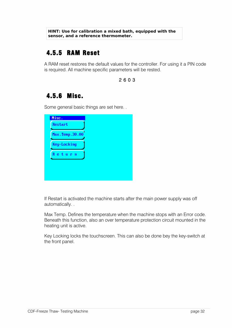
4.5.6 Misc.
Some general basic things are set here. .
If Restart is activated the machine starts after the main power supply was off automatically. .
Max Temp. Defines the temperature when the machine stops with an Error code. Beneath this function, also an over temperature protection circuit mounted in the heating unit is active.
Key Locking locks the touchscreen. This can also be done bey the key-switch at the front panel.
CDF-Freeze Thaw- Testing Machine page 32
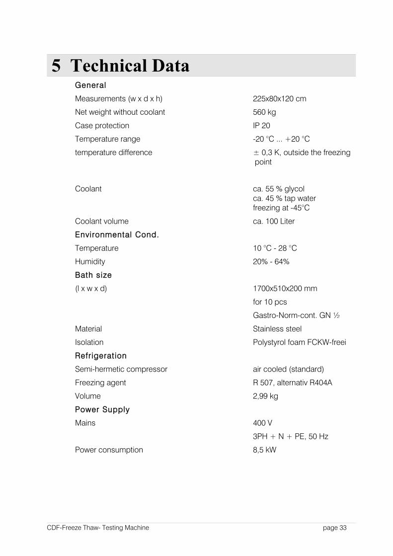
5 Technical Data General
Measurements (w x d x h) 225x80x120 cm
Net weight without coolant 560 kg
Case protection IP 20
Temperature range -20 °C ... +20 °C
temperature difference ± 0,3 K, outside the freezing point
Coolant ca. 55 % glycolca. 45 % tap waterfreezing at -45°C
Coolant volume ca. 100 Liter
Environmental Cond.
Temperature 10 °C - 28 °C
Humidity 20% - 64%
Bath size
(l x w x d) 1700x510x200 mm
for 10 pcs
Gastro-Norm-cont. GN ½
Material Stainless steel
Isolation Polystyrol foam FCKW-freei
Refr igerat ion
Semi-hermetic compressor air cooled (standard)
Freezing agent R 507, alternativ R404A
Volume 2,99 kg
Power Supply
Mains 400 V
3PH + N + PE, 50 Hz
Power consumption 8,5 kW
CDF-Freeze Thaw- Testing Machine page 33
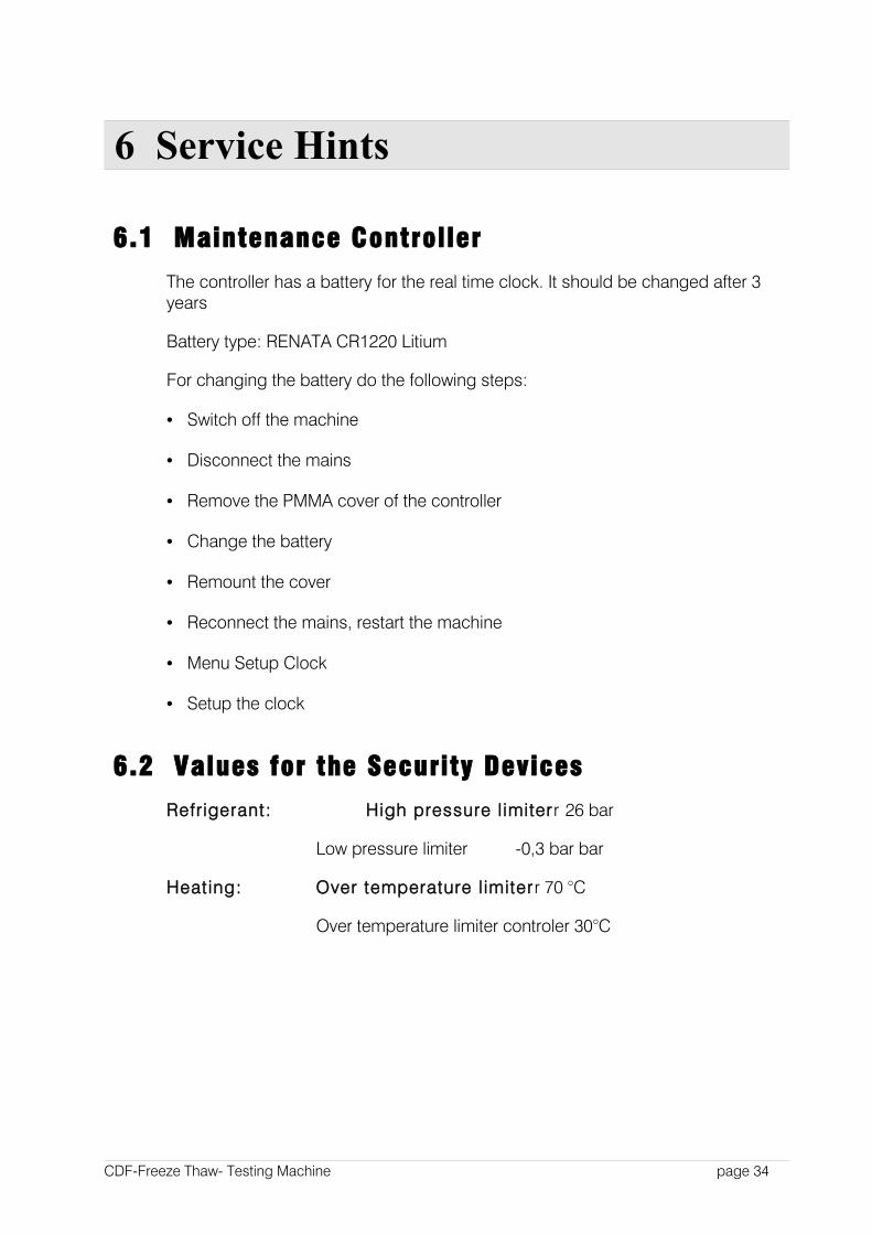
6 Service Hints
6.1 Maintenance Controller
The controller has a battery for the real time clock. It should be changed after 3 years
Battery type: RENATA CR1220 Litium
For changing the battery do the following steps:
• Switch off the machine
• Disconnect the mains
• Remove the PMMA cover of the controller
• Change the battery
• Remount the cover
• Reconnect the mains, restart the machine
• Menu Setup Clock
• Setup the clock
6.2 Values for the Security Devices
Refrigerant: High pressure l imiterr 26 bar
Low pressure limiter -0,3 bar bar
Heating: Over temperature l imiter r 70 °C
Over temperature limiter controler 30°C
CDF-Freeze Thaw- Testing Machine page 34
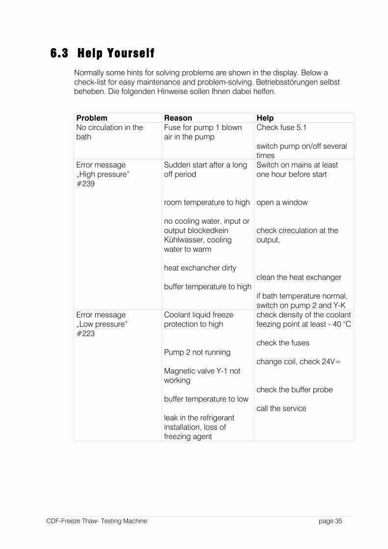
6.3 Help Yourself
Normally some hints for solving problems are shown in the display. Below a check-list for easy maintenance and problem-solving. Betriebsstörungen selbst beheben. Die folgenden Hinweise sollen Ihnen dabei helfen.
Problem Reason HelpNo circulation in the bath
Fuse for pump 1 blownair in the pump
Check fuse 5.1
switch pump on/off several times
Error message„High pressure“#239
Sudden start after a long off period
room temperature to high
no cooling water, input or output blockedkein Kühlwasser, cooling water to warm
heat exchancher dirty
buffer temperature to high
Switch on mains at least one hour before start
open a window
check cireculation at the output,
clean the heat exchanger
if bath temperature normal, switch on pump 2 and Y-K
Error message„Low pressure“#223
Coolant liquid freeze protection to high
Pump 2 not running
Magnetic valve Y-1 not working
buffer temperature to low
leak in the refrigerant installation, loss of freezing agent
check density of the coolant feezing point at least - 40 °C
check the fuses
change coil, check 24V=
check the buffer probe
call the service
CDF-Freeze Thaw- Testing Machine page 35

Problem Reason HelpTouchscreen accepts no input
Key switch off
keyboard off by softwaret
Switch S1 on PCB board left Electrical cabinet, or display frame bended (after transport)
Turn on key switch
Switch the machine on / off Setup Menu Misc. Keyboard lock = off
switch S1 right
call service
To much temperature deviations
Reference sensor not below a specimen container
liquid level to high or to low
parameters set wrong
Place the sensor right below a container
set the right level
check the setup menuMachine off without error message
Short interrupt on the mains or phase L3
24V power supply defect
Check the power supply- all 3 phases!
Check all 4 yellow LEDs on the controller board
Machine is no heating Fuse blown Check fusesError message„Bath to hot“
Magnetic valve Y-K broken
T max set to low
reference probe in the bath broken
to less freezing agent
Change coiln
check T max in the System Menu
change probe
call service
CDF-Freeze Thaw- Testing Machine page 36
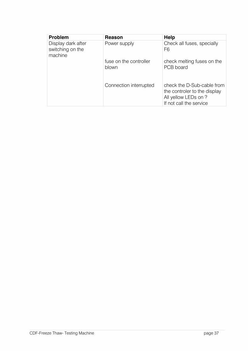
Problem Reason HelpDisplay dark after switching on the machine
Power supply
fuse on the controller blown
Connection interrupted
Check all fuses, specially F6
check melting fuses on the PCB board
check the D-Sub-cable from the controler to the displayAll yellow LEDs on ?If not call the service
CDF-Freeze Thaw- Testing Machine page 37
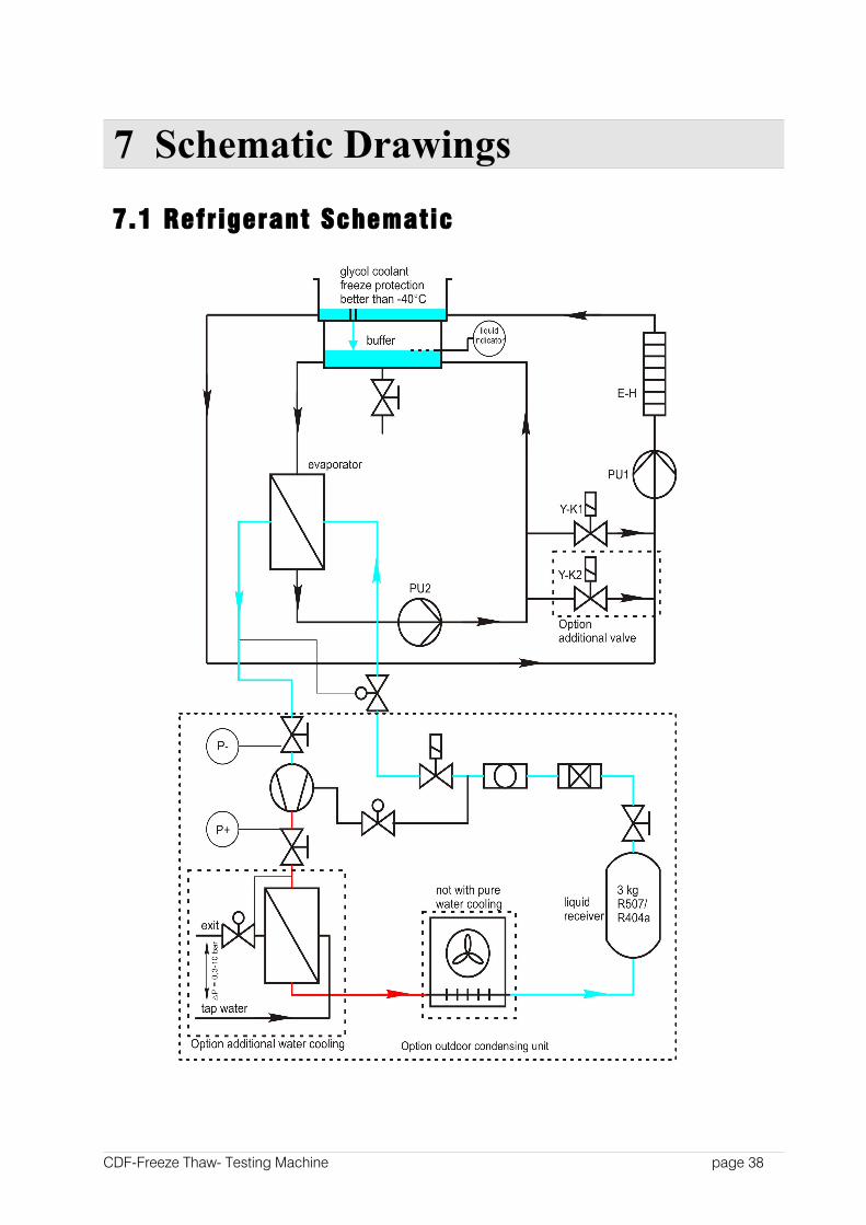
7 Schematic Drawings
7.1 Refrigerant Schematic
CDF-Freeze Thaw- Testing Machine page 38
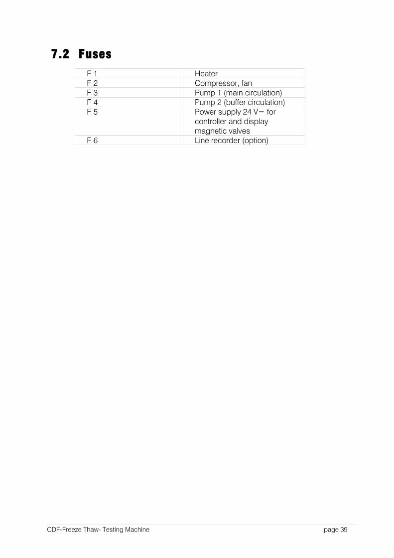
7.2 Fuses
F 1 HeaterF 2 Compressor, fanF 3 Pump 1 (main circulation)F 4 Pump 2 (buffer circulation)F 5 Power supply 24 V= for
controller and displaymagnetic valves
F 6 Line recorder (option)
CDF-Freeze Thaw- Testing Machine page 39
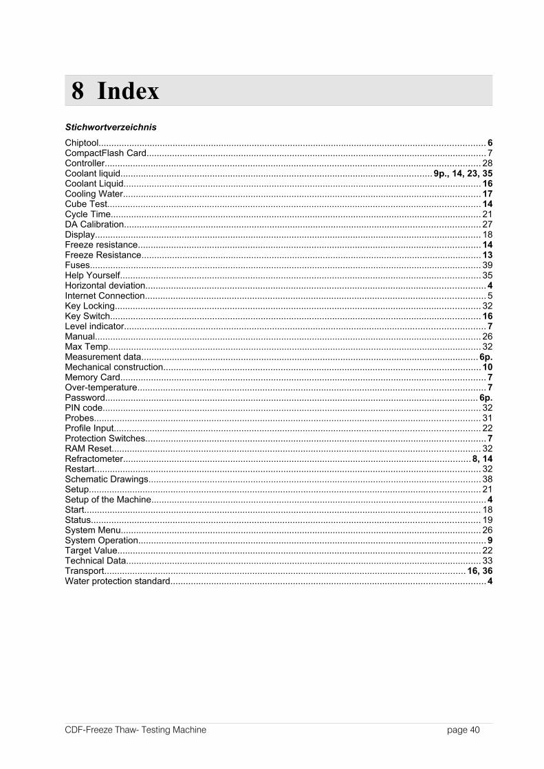
8 IndexStichwortverzeichnis
Chiptool....................................................................................................................................................... 6CompactFlash Card..................................................................................................................................... 7Controller................................................................................................................................................... 28Coolant liquid..........................................................................................................................9p., 14, 23, 35Coolant Liquid............................................................................................................................................ 16Cooling Water............................................................................................................................................ 17Cube Test.................................................................................................................................................. 14Cycle Time................................................................................................................................................. 21DA Calibration........................................................................................................................................... 27Display....................................................................................................................................................... 18Freeze resistance...................................................................................................................................... 14Freeze Resistance..................................................................................................................................... 13Fuses......................................................................................................................................................... 39Help Yourself............................................................................................................................................. 35Horizontal deviation..................................................................................................................................... 4Internet Connection..................................................................................................................................... 5Key Locking............................................................................................................................................... 32Key Switch................................................................................................................................................. 16Level indicator............................................................................................................................................. 7Manual....................................................................................................................................................... 26Max Temp.................................................................................................................................................. 32Measurement data....................................................................................................................................6p.Mechanical construction............................................................................................................................10Memory Card............................................................................................................................................... 7Over-temperature........................................................................................................................................ 7Password.................................................................................................................................................. 6p.PIN code.................................................................................................................................................... 32Probes....................................................................................................................................................... 31Profile Input............................................................................................................................................... 22Protection Switches..................................................................................................................................... 7RAM Reset................................................................................................................................................ 32Refractometer........................................................................................................................................8, 14Restart....................................................................................................................................................... 32Schematic Drawings.................................................................................................................................. 38Setup......................................................................................................................................................... 21Setup of the Machine................................................................................................................................... 4Start........................................................................................................................................................... 18Status........................................................................................................................................................ 19System Menu............................................................................................................................................. 26System Operation........................................................................................................................................ 9Target Value.............................................................................................................................................. 22Technical Data........................................................................................................................................... 33Transport............................................................................................................................................. 16, 36Water protection standard...........................................................................................................................4
CDF-Freeze Thaw- Testing Machine page 40