Embed Size (px)
Citation preview
USER MANUAL
B. Presentation

2010 Release
B-2
1 PRESENTATION
CONTENTS
1 PRESENTATION 2
1.1 IDENTIFICATION 3 1.1.1 ROLL CAGE 3 1.1.2 CHASSIS NUMBER 3 1.1.3 HOLOGRAMS 4 1.1.4 MARKINGS 4 1.2 DIMENSIONS 5 1.3 CAPACITIES 6 1.4 GENERAL CHARACTERISTICS 7 1.5 HANDLING 8 1.5.1 LIFTING AT FRONT 8 1.5.2 LIFTING AT REAR 8 1.5.3 TOWING AT FRONT 8 1.5.4 TOWING AT REAR 8 1.6 USING THE CAR 9 1.6.1 CONTROL PANEL 9 1.6.2 DISPLAY 10 1.6.3 BASIC PROCEDURES 14 1.6.4 ADJUSTING THE DRIVING POSITION 17 1.6.5 VENTILATION 18 1.6.6 FUEL LEVEL 19 1.7 SAFETY EQUIPMENT 20 1.7.1 EXTINGUISHER 20 1.7.2 CIRCUIT-BREAKER 22 1.7.3 OTHER SAFETY EQUIPMENT 23 1.7.4 PASSENGER SEAT 23 1.8 BALLAST 24 1.9 APPENDICES 25 1.9.1 LIST OF MARKED PARTS 25 1.9.2 RECOMMENDATIONS REGARDING REPLACEMENT OF MECHANICAL COMPONENTS 27 1.9.3 LIST OF ALARMS 29

2010 Release
B-3
1.1 IDENTIFICATION 1.1.1 ROLL CAGE The roll cage plate is located on the roll cage�’s rear left hand strut. It features the following information:
Manufacturer Model Serial number
The roll cage homologation number is: 27-31/675 (homologated by the DMSB).
1.1.2 CHASSIS NUMBER The chassis number is engraved on the passenger side of the centre crossmember.
Type Year Serial N°

2010 Release
B-4
1.1.3 HOLOGRAMS
The bodywork parts and certain mechanical components are identified using embossed hologram disks (see Appendix/List of marked parts). The wording �“NO PAINT �” indicates you must not paint over the hologram under any circumstances. The presence of the holograms is mandatory. The absence of hologram(s) may be regarded as technical non-compliance and event organizers may require that the part(s) in question be replaced.
1.1.4 MARKINGS Certain mechanical components are identified using an engraving (see Appendix/List of marked parts). An engraving is proof that the part is genuine, but does not confirm that it complies with regulations. The absence of engraving(s) may be regarded as technical non-compliance and event organizers may require that the part(s) in question be replaced.
Supplier engraving
Renault Sport engraving

2010 Release
B-5
1.2 DIMENSIONS
Overall height 1,480mm
Overall length (Mk.I) 3,991mm
Overall width 2,025mm
Wheel base 2,585mm
Front track (at axle) 1,538mm
Rear track (at axle) 1,520mm
Total weight (without fuel) 1,060kg
Front/rear split [%] 63.6 / 36.4

2010 Release
B-6
1.3 CAPACITIES
Capacity Characteristics Comments
Fuel tank 54L
Free practice or private testing: SP 98 grade unleaded
Events: see technical regulations
Tolerance:
- 0L
+ 1.5L
Engine lubricant 5L Elf Excelcium NF 5W40 See technical regulations
Gearbox lubricant 1.4L Elf HTX 752 75 W 140 See technical regulations
Coolant 6.5L Glaceol RX Type D
Front/rear brake fluid 0.8L Elf XT Dot 5
Use of Elf Excelcium 5W40 engine oil is mandatory (refer to technical regulations). You are free to use alternatives for all other fluids, but they must comply with the characteristics specified above.
BRAKE FLUID
Cars are delivered with “Elf XT Dot 5” brake fluid. When changing any type of fluid, the old fluid must be completely drained and the braking circuit must be cleaned before the new fluid can be added. The compatibility of the hydraulic systems (braking and clutch) must be checked before using any fluid other than that which has been recommended.

2010 Release
B-7
1.4 GENERAL CHARACTERISTICS
Description Dimensions SCx 0.77
FR SCz 0.15
RR SCz -0.1
Front ground clearance at standstill 110mm
Rear ground clearance at standstill 200mm
Front camber at standstill -3.5 degrees
Rear camber at standstill -2.0 degrees
Front/rear tyre radius under load 306mm
Vertical stiffness of front/rear tyre (camber = –3°, P=2bar) 240N/mm
Front/rear tyre dimensions 20/61-17
Front/rear wheel dimensions 8�’�’ x 17�’�’
Front unsprung mass per ¼ of vehicle 53kg
Rear unsprung mass per ¼ of vehicle 38kg
Front sprung mass per ¼ of vehicle 317kg
Rear sprung mass per ¼ of vehicle 172kg
Engine power 152,3kW (207bhp)
Max. engine speed 7,500rpm
Max. engine torque 223N.m (22.7m.kg)
Front camber variation
Variation in front roll centre
Front wheel alignment variation at compression
Front wheel alignment variation at rebound
See section 4-1 Front axle
Front shock absorber / wheel installation kinematics ratio 0.96
Rear camber variation
Variation in rear roll centre
Rear wheel alignment variation at compression
Rear wheel alignment variation at rebound
See section 4-2 Rear axle
Rear shock absorber / wheel installation kinematics ratio 0.9

2010 Release
B-8
1.5 HANDLING
1.5.1 LIFTING AT FRONT The vehicle is raised at the front using a jack. The jack must be positioned beneath the pad provided.
1.5.2 LIFTING AT REAR The vehicle is raised at the rear using a jack. The jack must be positioned beneath the pad provided.
1.5.3 TOWING AT FRONT The vehicle may be towed from the front using the strap provided.
1.5.4 TOWING AT REAR The vehicle may be towed from the rear using the strap provided.

2010 Release
B-9
1.6 USING THE CAR 1.6.1 CONTROL PANEL
1 �– Power supply 2 �– Starter 3 �– Fuel pump override 4 �– Front wipers 5 �– Windshield demister 6 �– Windshield washer 7 �– Extinguisher 8 �– Indicators 9 �– Headlights 10 �– Rear rain lights 11 �– Speed limiter 12 �– Ignition/injection
NB: All of the switches enable their respective command when they are in the up position, with the exception of the indicator switch.
Note: You are advised to use a window washer type fluid in order to clean the
control panel. All hydrocarbon-based products should be avoided.
1 2 3
4
5 6 7 8 9
10
11 12
2010 Release
B-10
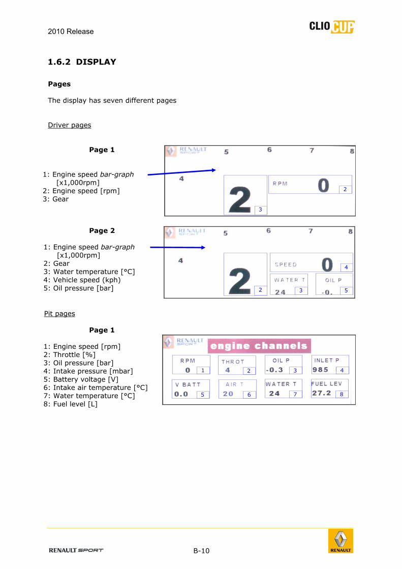
1.6.2 DISPLAY
Pages The display has seven different pages Driver pages
Page 1 1: Engine speed bar-graph
[x1,000rpm] 2: Engine speed [rpm] 3: Gear
Page 2 1: Engine speed bar-graph
[x1,000rpm] 2: Gear 3: Water temperature [°C] 4: Vehicle speed (kph) 5: Oil pressure [bar]
Pit pages
Page 1
1: Engine speed [rpm] 2: Throttle [%] 3: Oil pressure [bar] 4: Intake pressure [mbar] 5: Battery voltage [V] 6: Intake air temperature [°C] 7: Water temperature [°C] 8: Fuel level [L]
3
4
8
7
6
5
1
2
3
5
2
3
4
2

2010 Release
B-11
Page 2
1: Barrel potentiometer voltage [mV]
2: Engine cut-off switch status 3: Gear
Page 3
Outputs diagnostics: 1: Coil short-circuit 2: Injector short-circuit 3: Other output short-circuit 4: Coil open circuit 5: Injector open circuit 6: Other output open circuit
Page 4
Inputs diagnostics: 1: Analog 0 2: Analog 1 3: Analog 2 4: Optional acquisition kit
Page 5 1: Front brake pressure [bar] 2: % pressure on front brakes 3: Rear brake pressure [bar] 4: Pressure split bar-graph [%]
Note: The information on pits page 5 is only available if the vehicle is fitted with the
optional data acquisition kit.
1
2
3
2
1
3
4
5
6
1
2
3
4
1
3
4
2

2010 Release
B-12
Changing pages The pages of the display may be changed by pressing on the push button indicated (13). Pressing briefly on this button (one second) moves the display from driver page 1 to driver page 2. Pressing this button for longer (more than 3 seconds) moves the display from one of the driver pages to one of the pit pages. Pressing briefly on the button then moves the display from one pit page to another. You can return to the driver pages by pressing the button for a longer period (more than 3 seconds). The display returns to the last driver page that was viewed. Note: It is impossible to change pages if an alarm is displayed on the dashboard.
Driver 1 Driver 2
Driver pages
<1s
Pit 1
Pit pages
<1s Pit 2 <1s
Pit 3 <1s
Pit 4 <1s
Pit 5
>3s
13

2010 Release
B-13
Alarms When an error occurs that must be acknowledged by the driver, an alarm appears on the dashboard display. Each alarm (1) is shown along with a critical value (2). In this example, the oil pressure is above the maximum threshold (cold oil). The list of alarms is provided in the Appendix.
LEDs The display is fitted with 6 engine speed indicator LEDs (1) (4 green and 2 red) and with two alarm LEDs (2) (blue).
Engine speed LEDs The LEDs light up as indicated in all gears, except neutral and reverse.
6350 6550 6850 7150 7300 7400
Engine speeds at which LEDs light up (in rpm)
1
2
1 2

2010 Release
B-14
1.6.3 BASIC PROCEDURES
Power-up Flick the vehicle�’s power supply switch (1) into the up (on) position. The home page appears when dashboard display first comes on, and then moves to one of the driver pages. Starting Once the vehicle�’s electrics are on, flick the vehicle's ignition switch (12) to the up (on) position. Check that the car is not in gear (the letter �“N�” should be displayed on one of the display screen�’s driver pages). Press on the start button (2) whilst lightly pressing on the accelerator until the engine starts.
The vehicle will only start if all of the electronic equipment is connected (Dashboard, Calculator and the New Technology Battery Master Switch) and working properly.
Turning off the engine Flick the ignition switch (12) to the down (off) position. Note: The vehicle’s electrics are still switched on.
Except in the event of an emergency stop, you are not advised to turn off the engine using the power supply switch (1). You also recommended to wait 30 seconds between switching off the engine and switching off the power supply. Respecting these two recommendations will guarantee optimum operation of the power steering.
Switching off the power supply
Flick the car�’s electrical power supply switch (1) to the down position (off) and hold there for at least half a second. The dashboard display is switched off. Note: Switching off the power supply also switches off the engine.

2010 Release
B-15
Changing gear
- Gearshift lever The gearshift lever (1) is located to the right of the steering wheel.
- Principle
Pull the gear lever to upshift, push the gear lever to downshift. The gear selected is displayed on the dashboard screen, on the �“driver�” pages and on the �“gear channels�” page.
- Switching from neutral to first gear Pull the gearshift lever half of its full travel.
- Switching from reverse to first gear Pull the gearshift lever its full travel.
- Switching from 1st gear to neutral Pull the unlocking lever (1) located on the pillar of the roll cage on the left of the steering wheel. Push the gearshift lever half of its full travel whilst keeping the unlocking lever actuated.
- Selecting reverse gear Pull the unlocking lever (1). Push the gearshift lever half of its full travel (from neutral) or its full travel (from first gear) whilst keeping the unlocking lever actuated.
1
1
1
2010 Release
B-16
Speed limiter The purpose of this function is to limit the vehicle's speed to 60kph. It is enabled and disabled by the driver. It is enabled and disabled using button (11) on the dashboard.
- Principle
Flicking the speed limiter switch (11) to the up position (on) triggers the speed limitation procedure. Engine revs are thus limited to those corresponding to a speed of 60kph.
Note: The speed limiter does not control the brakes. Consequently, the vehicle
speed will only slow rapidly to 60kph if the driver applies the brakes.
When the speed reaches 60kph, with the exception of the specific conditions described below, vehicle speed is then controlled by the ECU. The message �“Pit Limiter�” appears on the display. To disable the speed limiter mode, the driver must flick the switch (11) to the down position (off). The message �“Pit Limiter�” disappears on the display.
- Specific conditions
The driver may only enable and disable the speed limiter when the vehicle is in one of the first three gears. Controlling the rain light The rain light is switched on by flicking the rear rain light switch (10) to the up position (on). The light is on continuously when enabled. However, it is lightning automatically with flashing phases in the following specific situations:
When the speed limiter function is enabled and the vehicle speed is less than equal to 60kph (flashes at 0.5Hz). For a period of 20 seconds after the engine stalls (flashes at 1Hz).
Procedure for resetting the oil pressure The oil pressure sensor is reset using the following procedure:
Switch off the main power supply (switch (1) on the control panel). Press the accelerator pedal to the floor. Switch on the vehicle's electrics (switch (1) on the control panel) while keeping the accelerator pedal pressed for at least 5 seconds. Check that the value of oil pressure have been reset.
Notes: This operation must be performed with the vehicle on a flat, level surface.
This operation also resetting the accelerometer and brake pressure sensors.

2010 Release
B-17
1.6.4 ADJUSTING THE DRIVING POSITION Adjusting the steering wheel To optimize the driving position, the height of the steering wheel may be adjusted. To adjust the steering wheel:
Loosen the two roll cage bar stay mounting bolts (1) on the steering column sleeve. Unlock the steering column�’s adjustment lever (2). Adjust the steering wheel position. Re-lock the lever. Tighten the two mounting bolts to 21Nm.
Adjusting the seat To move the seat forwards or backwards, unscrew the brackets from the body floor, place the seat in the required position and the re-screw the brackets in the appropriate holes (1). The height and angle of the seat may be adjusted in similar fashion by altering its attachment points on the brackets (2).
1 2
1
2

1.6.5 VENTILATION The vehicle has 4 air vents:
2 on the dashboard. 2 on the roof.
The air vents may be directed and/or plugged. Air is supplied to the two dashboard air vents from the blower, enabled by a switch (5) on the control panel.

2010 Release
B-19
1.6.6 FUEL LEVEL The fuel level (1) is shown on the display�’s �“engine channels�” page.
Once the vehicle�’s electrics are switched on (switch (1) on the control panel) and until the ignition is next enabled (switch (12) on the control panel), the volume displayed (1) corresponds to the amount of fuel recorded by the fuel tank gauge.
One second after enabling the ignition (switch (12) on the control panel), the volume indicated by the gauge is saved if the following conditions are met:
Vehicle speed is zero. Engine speed is zero (engine off). There is no electrical fault on the gauge.
Subsequently, the volume displayed is decremented by the injection ECU (based on the length of time injectors are open and the fuel flow rate)
After being driven, in order to update the volume of fuel displayed using information from the gauge, the vehicle�’s electrics must be switched off and switched back on (switch (1) on the control panel).
Note: In order that the information displayed regarding fuel volume is as accurate
as possible, you are advised to update the gauge when the vehicle has its wheels fitted and is at rest on a flat surface.
The displayed value is only indicative. We highly recommend not to follow this only value to calculate the remaining fuel quantity regarding the technical regulations (article 16).
The maximum quantity of fuel in the tank is 54 litres, whereas the displayed value cannot exceed 49 litres. This means that, between 54 and 49 litres, the displayed value will remain 49 litres, even if the measured and the calculated levels have decreased.
1

2010 Release
B-20
1.7 SAFETY EQUIPMENT 1.7.1 EXTINGUISHER Each vehicle is equipped with an extinguishing system targeting the driver compartment and the engine compartment. The fire extinguisher is located in the driver compartment on the right of the driver.
The system consists of 3 jets:
1 in the driver compartment on the left of the steering wheel
2 in the engine compartment:
1 pointing at the exhaust manifold (1): 1 pointing at the intake (2):
1
2

2010 Release
B-21
Use The extinguishing system is controlled by a unit located next to the fire extinguisher, on the right of the driver.
The extinguishing system can be triggered in one of three ways:
The driver presses on the button (7) on the control panel on the dashboard.
The driver presses on the button (1) on the control unit.
By pressing the button (1) located on the outside of the vehicle at the base of the windshield pillar, and which must be indicated by a red letter E.
The extinguishing system will only be triggered if the switch (2) is in the up position (on).
The control unit is delivered without batteries in order to avoid any accidental triggering of the extinguishing system. Ensure that you install a battery in the control unit�’s compartment (4) before using the vehicle for the first time.
1
3 2
4
1

2010 Release
B-22
1.7.2 CIRCUIT-BREAKER There is an emergency circuit breaker control at the base of the windshield pillar (1). It must be indicated by a sticker with a red lightening symbol on a blue background. This button may be used to switch off the vehicle�’s electrics from the outside.
Checks
- Extinguisher cylinder compliance check The following information must be clearly visible on the cylinder:
Serial number. Capacity and weight or volume of extinguisher product. Activation date or date of last system check. Date of next service. Homologation number.
Take care not to exceed the extinguisher�’s next scheduled service date.
- Pressure check The pressure of the cylinder may be checked using a manometer placed on the cylinder. The needle must be situated in the green area on the manometer dial.
- Wiring harness check
To check that the extinguisher is working properly, flick the switch (2) to the down position (off-test) and press on one of the three trigger buttons. If the test ok LED (3) lights up, the extinguisher and its control circuits are working properly. If it does not light up, check the extinguisher control unit�’s wiring.
1

2010 Release
B-23
1.7.3 OTHER SAFETY EQUIPMENT
The presence of the window safety net (ref. 77 11 160 041) on the driver side of the roll cage is mandatory. It is mandatory for foam (ref 77 11 160 040) to be placed on all parts of the roll cage with which the driver�’s helmet may come into contact. The seats (original part ref: 77 11 160 035 and XL version part ref: 77 11 160 192) and the harness (ref 77 111 160 036) are compatible with the HANS system.
The use of « HANS » sustem must be in compliance with the installation standard of FIA.
1.7.4 PASSENGER SEAT A passenger seat may be installed on Clio Cup using the supports with part ref 77 11 160 381.
So as not to damage the fire extinguisher and the extinguisher lines, it is essential to comply with the following passenger seat settings:
The seat must be positioned towards the rear, in the second to last position (1). The seat must be positioned in the highest position (2).
Front of vehicle
1
2

2010 Release
B-24
1.8 BALLAST Where championship technical regulations state that vehicles must carry a minimum weight, it is mandatory to use the following ballast plates:
1kg: ref 77 11 160 299
2kg: ref 77 11 160 300
5kg: ref 77 11 160 301
These plates must be mounted on the body using two drilled head bolts with part ref 77 11 160 302 (sold in sets of 2). In all cases, these ballast plates will be fixed at the seat rail sites, between these ones and the frame (refer to the current Technical Regulations).

2010 Release
B-25
1.9 APPENDICES
1.9.1 LIST OF MARKED PARTS All parts that are specific to Clio Cup are engraved The following genuine Renault parts are identified either by a �“Renault Sport�” laser engraving or by a hologram( its presence is compulsory with NO PAINT)
Part name Reference no. Marking
Fuel rail 77 11 160 032
Rack riser shim 77 11 160 016
Steering unit assembly 77 11 160 046
Extended steering tie-rod 77 11 160 144
Rear disc hub 77 11 160 107
1kg ballast plate 77 11 160 299
2kg ballast plate 77 11 160 300
5kg ballast plate 77 11 160 301
Throttle valve unit 77 11 160 249
1° wheel alignment shim 77 11 160 169
30' wheel alignment shim 77 11 160 170
20' wheel alignment shim 20' 77 11 160 171
10' wheel alignment shim 10' 77 11 160 172
1° Camber alignment shim 77 11 160 173
30' Camber alignment shim 77 11 160 174
20' Camber alignment shim 20' 77 11 160 175
10' Camber alignment shim 10' 77 11 160 176
Point F support 77 11 160 018
Fitted front lower arm 77 11 162 598
Right QQ' tie-rod 77 11 160 146
Left QQ' tie-rod 77 11 160 147
Track shim 77 11 160 154
Anti-roll bar 77 11 160 155
Rack lock shim 77 11 160 142
Point F upper cup 77 11 160 017
Left-hand steering ball joint holder 77 11 160 319
Right-hand steering ball joint holder 77 11 160 318
Front disc 77 11 160 361
Front left caliper 77 11 160 363
Front right caliper 77 11 160 362
Clutch friction 77 11 160 229 77 11 162 520
Clutch mechanism 77 11 160 287
"Renault Sport" laser engraving

2010 Release
B-26
Part name Alpine part ref. Marking
Front bumper 77 11 162 535
Rear bumper 77 11 160 029
Rear spoiler 77 11 160 033
Fuel tank 77 11 160 061
Right door panel 77 11 160 064
Left door panel 77 11 160 065
Clio Cup 85 dashboard 77 11 160 216
Clio Cup 85 console 77 11 160 263
Rear diffuser 77 11 162 532
Right-hand headlight 77 11 162 545
Left-hand headlight 77 11 162 544
Front left door window glass 77 11 160 089
Front right door window glass 77 11 160 388
Windshield glass 77 11 160 087
Rear window glass 77 11 160 088
Rear right light 77 11 160 080
Left rear light 77 11 160 079
Left quarter panel glass 77 11 160 090
Right quarter panel glass 77 11 160 091
Battery 77 11 127 895
Steel electric extinguisher 77 11 160 038
Roof vent 77 11 160 129
Driver compartment diffuser 77 11 160 315
Left door 77 11 160 395
Right door 77 11 160 394
Hood 77 11 160 396
Tailgate 77 11 160 397
Front right fender 77 11 160 398
Front left fender 77 11 160 399
Front end crossmember 77 11 160 086
Right spoiler end 77 11 160 404
Left spoiler end 77 11 160 405
Braking amplifier 77 11 160 156
Fuel pump 77 11 160 406
Gearbox control stay 77 11 160 148
Left-hand rear-view mirror 77 11 162 550
Right-hand rear-view mirror 77 11 162 551
Left-hand rear-view mirror shell 77 11 162 548
Right-hand rear-view mirror shell 77 11 162 549
Left-hand radiator convergent 77 11 160 389
Right-hand radiator convergent 77 11 160 390
Motor fan 77 11 160 391
Water radiator 77 11 160 206
Hologram

2010 Release
B-27
1.9.2 RECOMMENDATIONS REGARDING REPLACEMENT OF MECHANICAL COMPONENTS
The mileage of the below parts must be monitored by the user throughout the vehicle�’s lifetime. The mileage stated in the table below is the maximum expected mileage before replacement, notwithstanding any incidents or accidents. Should any component become faulty or its condition deteriorate before reaching the stated mileage, please contact Renault Sport Technologies. Note: This list may not under any circumstances be considered to be part of the
manufacturer’s warranty.
Point F ball joint 7,500 km
Wishbone balljoints 3,500
km
Point E ball joint 7,500
km
Point F' ball joint 7,500 km
Wheel bearing 5,000 km
EE' support 7,500 km
Shock absorbers 5,000 km
Bump stop 5,000 km
Support strut 15,000 km
Anti-roll ball joint 7,500 km
Wheel stud and nut 5,000 km
Point F ball joint 7,500 km
Point E ball joint 7,500 km
Point A ball joint 7,500 km
Wheel bearing
5,000 km
Shock absorbers
5,000 km
Bump stop
5,000 km
Wheel stud and nut
5,000 km
Front axle
Rear axle

2010 Release
B-28
Power steering module 15,000 km
Steering unit 7,500 km
Axial ball joint 7,500 km
Point H ball joint 7,500 km
Gearbox 7,500 km
Clutch friction 5,000 km
Clutch mechanism 5,000 km
Drivetrains 5,000 km
Engine 10,000 km
Starter 10,000 km
Alternator 10,000 km
Throttle position sensor 5,000 km
Engine mounting cover 5,000 km
Gearbox mounting 5,000 km
Front brake disc 5,000 km
Front brake caliper 10,000 km
Rear brake disc 10,000 km
Rear brake caliper 10,000 km
Engine
Brakes
Note: Particular attention must be paid to the state of the fastenersafter any work has been carried out.
Steering
Kinematic chain

2010 Release
B-29
1.9.3 LIST OF ALARMS
Message LED Meaning Threshold
- Left Min. water temperature <= 30°C
�“V BAT MIN�” V batt <= 10V
+ value Right Min. battery voltage
and revs >= 4,000rpm
�“V BAT MAX�” V batt >= 15V
+ value Right Max. battery voltage
and revs <= 2,000rpm
"AIR T"
+ value Right Max. air temperature Air T >= 90°C
�“OILP�” Oil P >= 6 bar
+ value Right Max. oil pressure
and revs <= 2,000rpm
�“Water T Max�”
+ value Right Max. water temperature >= 110°C
�“OILP�” Oil P <= 2 bar
+ value Right Min. oil pressure
and revs >= 3,000rpm
"Throttle - def" - Electrical fault on throttle position sensor -
"Inlet P - def" - Electrical fault on intake pressure sensor -
"Air T - def" - Electrical fault on air intake temperature sensor -
"Oil P - def" - Electrical fault on oil pressure sensor -
"Water T - def" - Electrical fault on water temperature sensor -
"VERLOG - Active" - Software lock enabled -
"CBNT - Can def" - CAN CBNT fault -
"DAE - minor def" - Minor fault on power steering module -
"DAE - major def" - Major fault on power steering module -
"V.V.T. - def" - V.V.T. servo control fault -
"Barrel - def" - Electrical fault on barrel position sensor -
"W.S.left - def" - Electrical fault on front left wheel speed sensor -
"W.S.right - def" - Electrical fault on front right wheel speed sensor -
"DAE-Power def" - Power supply fault on power steering module -
"INJ.-Power def" - Injector power supply fault -
"IGN.-Power def" - Ignition coil power supply fault -
"PUMP-Power def" - Fuel pump power supply fault -
"Pit Limiter" - Speed limiter enabled -