Embed Size (px)
Citation preview

User Manual
ASMB-913I
Dual LGA 2011-R3 Intel Xeon® E5-2600v3 EATX Server Board

CopyrightThe documentation and the software included with this product are copyrighted 2015by Advantech Co., Ltd. All rights are reserved. Advantech Co., Ltd. reserves the rightto make improvements in the products described in this manual at any time withoutnotice. No part of this manual may be reproduced, copied, translated or transmittedin any form or by any means without the prior written permission of Advantech Co.,Ltd. Information provided in this manual is intended to be accurate and reliable. How-ever, Advantech Co., Ltd. assumes no responsibility for its use, nor for any infringe-ments of the rights of third parties, which may result from its use.
AcknowledgementsIntel and Pentium are trademarks of Intel® Corporation.
Microsoft Windows and MS-DOS are registered trademarks of Microsoft® Corp.
All other product names or trademarks are properties of their respective owners.
Product Warranty (2 years)Advantech warrants to you, the original purchaser, that each of its products will befree from defects in materials and workmanship for two years from the date of pur-chase.
This warranty does not apply to any products which have been repaired or altered bypersons other than repair personnel authorized by Advantech, or which have beensubject to misuse, abuse, accident or improper installation. Advantech assumes noliability under the terms of this warranty as a consequence of such events.
Because of Advantech’s high quality-control standards and rigorous testing, most ofour customers never need to use our repair service. If an Advantech product is defec-tive, it will be repaired or replaced at no charge during the warranty period. For out-of-warranty repairs, you will be billed according to the cost of replacement materials,service time and freight. Please consult your dealer for more details.
If you think you have a defective product, follow these steps:
1. Collect all the information about the problem encountered. (For example, CPU speed, Advantech products used, other hardware and software used, etc.) Note anything abnormal and list any onscreen messages you get when the problem occurs.
2. Call your dealer and describe the problem. Please have your manual, product, and any helpful information readily available.
3. If your product is diagnosed as defective, obtain an RMA (return merchandise authorization) number from your dealer. This allows us to process your return more quickly.
4. Carefully pack the defective product, a fully-completed Repair and Replacement Order Card and a photocopy proof of purchase date (such as your sales receipt) in a shippable container. A product returned without proof of the purchase date is not eligible for warranty service.
5. Write the RMA number visibly on the outside of the package and ship it prepaid to your dealer.
Part No. 2001913I00 Edition 1
Printed in Taiwan June 2015
ASMB-913I User Manual ii

A Message to the Customer
Advantech Customer Services
Each and every Advantech product is built to the most exacting specifications toensure reliable performance in the harsh and demanding conditions typical of indus-trial environments. Whether your new Advantech equipment is destined for the labo-ratory or the factory floor, you can be assured that your product will provide thereliability and ease of operation for which the name Advantech has come to beknown. Your satisfaction is our primary concern. Here is a guide to Advantech’s cus-tomer services. To ensure you get the full benefit of our services, please follow theinstructions below carefully.
Technical Support
We want you to get the maximum performance from your products. So if you run intotechnical difficulties, we are here to help. For the most frequently asked questions,you can easily find answers in your product documentation. These answers arenormally a lot more detailed than the ones we can give over the phone.
So please consult this manual first. If you still cannot find the answer, gather all theinformation or questions that apply to your problem, and with the product close athand, call your dealer. Our dealers are well trained and ready to give you the supportyou need to get the most from your Advantech products. In fact, most problemsreported are minor and are easily solved over the phone.
In addition, free technical support is available from Advantech engineers everybusiness day. We are always ready to give advice on application requirements orspecific information on the installation and operation of any of our products.
iii ASMB-913I User Manual

Declaration of Conformity
FCC
This device complies with the requirements in part 15 of the FCC rules:
Operation is subject to the following two conditions:
This device may not cause harmful interference This device must accept any interference received, including interference that
may cause undesired operation.
This equipment has been tested and found to comply with the limits for a Class A dig-ital device, pursuant to Part 15 of the FCC Rules. These limits are designed to pro-vide reasonable protection against harmful interference when the equipment is oper-ated in a commercial environment. This equipment generates, uses, and can radiateradio frequency energy and, if not installed and used in accordance with the instruc-tion manual, may cause harmful interference to radio communications. Operation ofthis device in a residential area is likely to cause harmful interference in which casethe user will be required to correct the interference at his/her own expense. The useris advised that any equipment changes or modifications not expressly approved bythe party responsible for compliance would void the compliance to FCC regulationsand therefore, the user's authority to operate the equipment.
Caution! There is a danger of a new battery exploding if it is incorrectly installed. Do not attempt to recharge, force open, or heat the battery. Replace the battery only with the same or equivalent type recommended by the man-ufacturer. Discard used batteries according to the manufacturer's instructions.
ASMB-913I User Manual iv

Peripheral Compatibility
Category Advantech PN Vendor Part Description Remarks
MBASMB-913I-00A1E Advantech Support BMC module
ASMB-913-00A1E Advantech Basic sku
CPU
Intel E5-2600 v3 product family
96MPXE-1.9-15M20T
IntelXEON 1.9G 15M 2011P 6CORE E5-2609V3
96MPXE-2.2-30M20T
IntelXEON 2.2G 30M 2011P 12CORE E5-2658V3
96MPXE-2.4-15M20T
IntelXEON 2.4G 15M 2011P 6CORE E5-2620V3
96MPXE-2.5-30M20T
IntelXEON 2.6G 20M 2011P 8CORE E5-2640V3
SATA HDD
2.5" & 3.5" SATA2 & SATA3 HDD device
Memory
DDR4 ECC-REG 2133/1866/1600 MHz DIMM
AQD-D4U4GR21-HG
Advantech 4G R-DDR4-2133 1.2V 512X8 HYX
AQD-D4U8GR21-HZ
Advantech 8G R-DDR4-2133 1.2V 512X8 HYX
AQD-D4U16R21-HZ Advantech 16G R-DDR4-2133 1.2V 512X8 HYX
Cooler/Heatsink
1960055362N001 AVCLGA-2011 square CPU cooler for 2U/4U chassis (145 W)
1960065684N001 CoolermasterLGA-2011 square CPU cooler for 4U chassis (160 W)
Option Card
PCA-AUDIO-HDA1E
Advantech Audio card
Riser Card
ASMB-RF348-21A1E
Advantech ASMB-RF348 (2U riser card) 2*PCI-E x4 + 1*PCI-E x8
ASMB-RF3X8-21A1E
Advantech ASMB-RF3X8 (2U riser card) 1*PCI-Ex4 + 2*PCI-X
PME
ASMB-FF208-02A1E
Advantech ASMB-FF208(PME board)2*PCIe x16 slot(Gen1 x8link)
ASMB-FF3PX-12A1E
Advantech ASMB-FF3PX(PME board) 2*PCI-X + 1*PCI slot
ASMB-FF20F-02A1E
Advantech ASMB-FF20F(PME board) 2*PCIe x16 slot(Gen3 x16link)
ASMB-FF3P8-12A1E
Advantech ASMB-FF3P8(PME board)2*PCIe x8 slot(1*Gen2 x8+ 1*Gen2 x4 link) + 1*PCIslot
v ASMB-913I User Manual

Initial InspectionBefore installing motherboard, please make sure that the following materials havebeen shipped:
1 x ASMB-913I EATX motherboard 1 x ASMB-913I Startup Manual 1 x Driver CD (user manual is included) 2 x Serial ATA HDD data cables 1 x I/O port bracket 2 x CPU power cable (8P) 2 x SATA power cable 1 x Warranty card
If any of these items are missing or damaged, contact distributor or sales representa-tive immediately. We have carefully inspected the ASMB-913I mechanically and elec-trically before shipment. It should be free of marks and scratches and in perfectworking order upon receipt. When unpacking the ASMB-913I, check it for signs ofshipping damage. (For example, damaged box, scratches, dents, etc.) If it is dam-aged or it fails to meet the specifications, notify our service department or local salesrepresentative immediately. Also notify the carrier. Retain the shipping carton andpacking material for inspection by the carrier. After inspection, we will make arrange-ments to repair or replace the unit.
Order Information
Part Number HDD Expansion Slot IPMI LAN
ASMB-913I-00A1E 8*SATA3 3*PCI-E x16 + 1* PME slot Yes 4
ASMB-913-00A1E 8*SATA3 3*PCI-E x16 + 1* PME slot - 2
ASMB-913I User Manual vi

Contents
Chapter 1 Overview...............................................11.1 Introduction ............................................................................................... 21.2 Features .................................................................................................... 21.3 Specifications ............................................................................................ 3
Table 1.1: Specifications ............................................................. 31.4 Board Layout, Jumpers and Connectors................................................... 5
Figure 1.1 Board Layout .............................................................. 5Figure 1.2 Rear I/O ...................................................................... 6Table 1.2: Onboard LAN LED Color Definition ............................ 6Table 1.3: Jumpers...................................................................... 6Table 1.4: Connectors ................................................................. 7Table 1.5: Onboard LED.............................................................. 8
1.5 Block Diagram........................................................................................... 8Figure 1.3 Block Diagram ............................................................ 8
1.6 System Memory ........................................................................................ 81.7 Memory Installation Procedures................................................................ 91.8 Processor Installation.............................................................................. 11
Chapter 2 Connections.......................................152.1 Introduction ............................................................................................. 162.2 USB Ports and LAN Ports (USB0~USB10/LAN1/LAN2/LAN3/LAN4)..... 162.3 VGA Connector ....................................................................................... 172.4 Serial Ports (COM1/COM2) .................................................................... 172.5 PS2 Keyboard and Mouse Header (KBMS2).......................................... 182.6 CPU Fan Connector (CPU FAN0/FAN1) ................................................ 18
Table 2.1: CPU FAN Pin Definition............................................ 192.7 System Fan Connector (SYS FAN0/FAN1/FAN2) .................................. 19
Table 2.2: SYS FAN Pin Definition ............................................ 192.8 Front Panel Connector (JFP1) ................................................................ 20
2.8.1 Power LED (JFP3) ...................................................................... 20Table 2.3: ATX Power Supply LED Status ................................ 20
2.8.2 External Speaker (JFP2 pins 1, 4, 7, 10) .................................... 202.8.3 HDD LED Connector (JFP1 Pins 2 & 5) ..................................... 212.8.4 Reset Connector (JFP1 Pins 9 & 12).......................................... 212.8.5 SNMP Connector (JFP1 Pins 8 & 11)......................................... 212.8.6 Case Open (JCASE1)................................................................. 21
2.9 SATA SGPIO (SATA_SGPIO_1) ............................................................ 222.10 Front Panel LAN Indicator Connector (LANLED1).................................. 232.11 Serial ATA Interface (SATA0-SATA5, sSATA0-sSATA1) ....................... 242.12 PCIe & PCI Expansion Slots ................................................................... 252.13 Auxiliary Power Connector (ATXPWR1/ATX12V1/ATX12V2) ................ 262.14 HD Audio Interface Connector (AUDIO1) ............................................... 272.15 LPC Connector (LPC1) for Optional TPM Module .................................. 282.16 Clear CMOS Connector (JCMOS1) ........................................................ 292.17 PMBUS Connector (PMBUS1)................................................................ 292.18 Front Panel SMBUS Connector (SMBUS1) ............................................ 302.19 IPMI Module Connector (BMC1) ............................................................. 312.20 VOLT1 Connector ................................................................................... 322.21 GPIO Connector...................................................................................... 33
Chapter 3 AMI BIOS ............................................35
vii ASMB-913I User Manual
3.1 Introduction ............................................................................................. 363.2 BIOS Setup ............................................................................................. 37
3.2.1 Main Menu.................................................................................. 373.2.2 Advanced BIOS Features Setup................................................. 383.2.3 IntelRCSetup .............................................................................. 503.2.4 Server Management ................................................................... 653.2.5 Security....................................................................................... 663.2.6 Boot ............................................................................................ 673.2.7 Save & Exit ................................................................................. 68
Chapter 4 Chipset Software Installation Utility 694.1 Before Beginning .................................................................................... 704.2 Introduction ............................................................................................. 70
4.2.1 Main Menu.................................................................................. 704.3 Windows 7 & 8/ Windows server 2008 & 2012 ....................................... 71
Chapter 5 VGA Setup ......................................... 735.1 Introduction ............................................................................................. 745.2 Windows Series Driver Setup ................................................................. 74
Chapter 6 LAN Configuration & USB 3.0.......... 776.1 LAN Configuration................................................................................... 78
6.1.1 Introduction ................................................................................. 786.1.2 Features...................................................................................... 786.1.3 Installation................................................................................... 786.1.4 Windows Series Driver Setup (LAN)........................................... 78
6.2 USB 3.0................................................................................................... 796.2.1 Introduction ................................................................................. 796.2.2 Windows Series Driver Setup ..................................................... 79
6.3 AHCI & SATA RAID ................................................................................ 80
Appendix A Programming the Watchdog Timer . 81A.1 Watchdog Timer Overview...................................................................... 82A.2 Programming the Watchdog Timer ......................................................... 82
Table A.1: Watchdog Timer Registers....................................... 84A.2.1 Example Programs ..................................................................... 84
Appendix B I/O Pin Assignments ......................... 89B.1 USB Header (USB89) ............................................................................. 90
Table B.1: USB Header (USB89) .............................................. 90B.2 USB3.0 Header(USB2_3 & USB4_5) ..................................................... 90
Table B.2: USB Header (USB23,USB45,USB67,USB89) ......... 90B.3 VGA Connector (VGA1).......................................................................... 91
Table B.3: VGA Connector (VGA1) ........................................... 91B.4 RS-232 Interface (COM2) ....................................................................... 91
Table B.4: RS-232 Interface (COM2) ........................................ 91B.5 External Keyboard Connector (KBMS2) ................................................. 92
Table B.5: External Keyboard Connector (KBMS2)................... 92B.6 System Fan Power Connector (SYSFAN0~2) ........................................ 92
Table B.6: Fan Power Connector (SYSFAN0/SYSFAN1/SYSFAN2)................................................................ 92
ASMB-913I User Manual viii
B.7 Power LED (JFP3) .................................................................................. 92Table B.7: Power LED (JFP1).................................................... 92
B.8 External Speaker Connector (JFP2) ....................................................... 93Table B.8: External Speaker Connector (JFP2)......................... 93
B.9 Reset Connector (JFP1) ......................................................................... 93Table B.9: Reset Connector (JFP1)........................................... 93
B.10 HDD LED Connector (JFP1) ................................................................... 93Table B.10:HDD LED Connector (JFP1) .................................... 93
B.11 ATX Soft Power Switch (JFP1) ............................................................... 94Table B.11:ATX Soft Power Switch (JFP1)................................. 94
B.12 Front panel SMBus Connector (SMBUS1).............................................. 94B.13 USB/LAN Ports (LAN1_USB0_1)............................................................ 94
Table B.12:USB Port................................................................... 94Table B.13:Giga LAN 10/100/1000 Base-T RJ-45 Port .............. 95
B.14 Audio Connector (AUDIO1)..................................................................... 95Table B.14:Front Panel Audio Connector (FPAUD1).................. 95
B.15 8-pin Alarm Board Connector (VOLT1)................................................... 95Table B.15:8-pin Alarm Board Connector (VOLT1) .................... 95
B.16 Case Open Connector (JCASE1) ........................................................... 96Table B.16:Case Open Connector (JFP1) .................................. 96
B.17 Front Panel LAN LED Connector (LANLED1)......................................... 96Table B.17:LAN LED Connector (LANLED1).............................. 96
ix ASMB-913I User Manual

ASMB-913I User Manual x

Chapter 1
1 Overview
1.1 IntroductionThe ASMB-913I serverboard is the most advanced Intel Xeon E5-2600 (V3) seriesboard for server-grade IPC applications that require high-performance computingpower & multi-expansion slots. This serverboard supports Intel Xeon E5-2600 (V3)series processor and DDR4 2133/1866/1600 MHz memory up to 512GB.
ASMB-913I provides three PCIe x16 slots (Gen3) + PME slot.
In addition, the ASMB-913I has four Gigabit Ethernet LAN ports via a dedicated PCIex1 bus, which offer bandwidth up to 500 MB/s, eliminating network bottlenecks.
The ASMB-913I has a RJ-45 LAN connector which is share link for IPMI functionallowing remote control
High reliability and outstanding performance makes ASMB-913I the ideal platform forindustrial server/networking applications.
By using the Intel C612 chipset, the ASMB-913I offers a variety of features such as 8onboard SATA III interfaces; it supports IRST (Intel Rapid Storage Technology) andprovides RAID 0, 1, 10 and 5 (Windows only*); and it has 3 USB 2.0 & 6 USB 3.0connectors.
These powerful I/O capabilities ensure even more reliable data storage capabilitiesand high-speed I/O peripheral connectivity.
1.2 FeaturesGeneral
Intel E5-2600 (v3) processor support: ASMB-913I supports two Intel E5-2600 (v3) series Quad/Six/Eight/Ten core processors.
High performance I/O capability: Four Gigabit LAN, 3 x PCIe x16 slot (x16 link) + 1 x PME slot, 8 x SATA connectors and 3 x 2.0 ports, 6 x USB 3.0.
Standard EATX form factor with industrial features: ASMB-913I provides industrial features like long product lifecycle, reliable operation under wide tem-perature range, watchdog timer, etc.
IPMI 2.0 support: ASMB-913I equipped with ASPEED 2400 BMC chip supports IPMI 2.0 (Intelligent Platform Management Interface 2.0) via share link LAN port.
KVM over IP: ASMB-913I KVM over IP function allows remote control of system through your own computer.
Note! 1. IPMI module will be included in ASMB-913I sku.2. Three USB 2.0 ports (1*Type- A) and six USB 3.0 ports (4 ports
from on-board 20-pin header)3. Please refer to the release note of each Linux OS for Intel's C612
chipset SATA RAID function support.
ASMB-913I User Manual 2

Chapter 1
Overview
1.3 Specifications
Table 1.1: Specifications
Processor
CPU
Dual Intel LGA2011 Xeon processor sockets Supports Intel Xeon E5-2600 (v3) series processor with
Quad/Six/Eight/Ten cores
Supports the TDP of processor up to 160 W
System Memory
Memory Capacity
Xeon processor supports DDR4 memory bus Total 16 memory slots provided Supports up to 512 GB memory
4 channels per processor, two dimm per channelMemory Type Supports DDR4 2133/1866/1600/1333 MHz ECC-REG Modules
DIMM SizesEach memory slot supports 1GB, 2GB, 4GB, 8GB, 16GB and 32GB memory modules
Memory Voltage 1.2 V
Error Detection Corrects single-bit errors Detects double-bit errors (using ECC memory)
On-Board Devices
Chipsets Intel C612 PCH provide 8xPCIe Gen2 lanes
Network Controllers
4 x Intel I210 Gigabit Ethernet Controller connected to C612 through PCIe Gen2 Lane.
Above network Supports 10BASE-T, 100BASE-TX, and 1000BASE-T, with RJ-45 output.
VGAASPEED AST2400/1400 controller with 64 MB VGA memory pro-vides basic 2D VGA function.
Super I/ONuvoton NCT6776D chip provide motherboard keyboard mouse, RS-232, parallel port and hardware monitor functions.
BMC (913I SKU Only) Intel i210 share link for IPMI/KVM
Input / Output
Serial ATA Total 8 x SATA ports and provide 6 Gb/s bandwidth. RAID 0, 1, 5, 10 support (Windows only. For Linux support
please refer to the note item 4 of chapter 1.1).
LAN 4 x RJ-45 LAN ports (10/100/1000 Base-T LAN).
USB
2 x USB3.0 at rear window. 2 x USB 3.0 internal header (4 ports).
1 x USB 2.0 internal headers (2 ports) 1 x internal Type-A USB port.
VGA 1 x VGA port.
Keyboard/Mouse Header (KBMS2)
Supports the standard PS/2 keyboard and mouse via PS/2 cable
Serial Port / Header 1 x internal header (2 x 5 2.5 mm pitch) for UART port. 1 x external DB9 UART at rear window.
Power Connector
System Power1 x 24-pin SSI EPS 12 V power connector (Input 12 V, 5 V, 3.3 V, 5 V standby)
CPU Power2 x 8 pin SSI EPS 12 V power connector for CPU & Memory power (12V)
3 ASMB-913I User Manual

PCIe slot power 1 x 8pin 12 V power connector for PCIe slot 12 V input
Expansion Slots
PCI-express
3 x PCI-E x16 slot (Gen3 x16 link)– PCIEX16_SLOT4(from CPU 1)– PCIEX16_SLOT5(from CPU 1)– PCIEX16_SLOT6(from CPU 0)
1 x PME slot*(from CPU 0)
System BIOS
BIOS Type 128 Mb SPI Flash EEPROM with AMI BIOS
PC Health Monitoring
Voltage Monitors for CPU Cores, +3.3 V, +5 V, +12 V, +5 V Standby, VBAT
FAN
Two 4-pin heads for CPU cooler and three 4-pin headers for system fan.
All fans with tachometer status monitoring Thermal control for all fan connectors
Temperature Monitoring for CPU (PECI) Monitoring for System (SIO)
Other Features(Case Open)
Chassis intrusion detection Chassis Intrusion header
Operating Environment / Compliance
RoHS RoHS Compliant 6/6 Pb Free
Environmental Spec.
Operating Temperature: 0 to 40° C Non-operating Temperature: -40 to 85° C Operating Relative Humidity: 10% to 90% (non-condensing) Non-operating Relative Humidity: 10% to 95% (non-condens-
ing)
Table 1.1: Specifications
ASMB-913I User Manual 4
Chapter 1
Overview
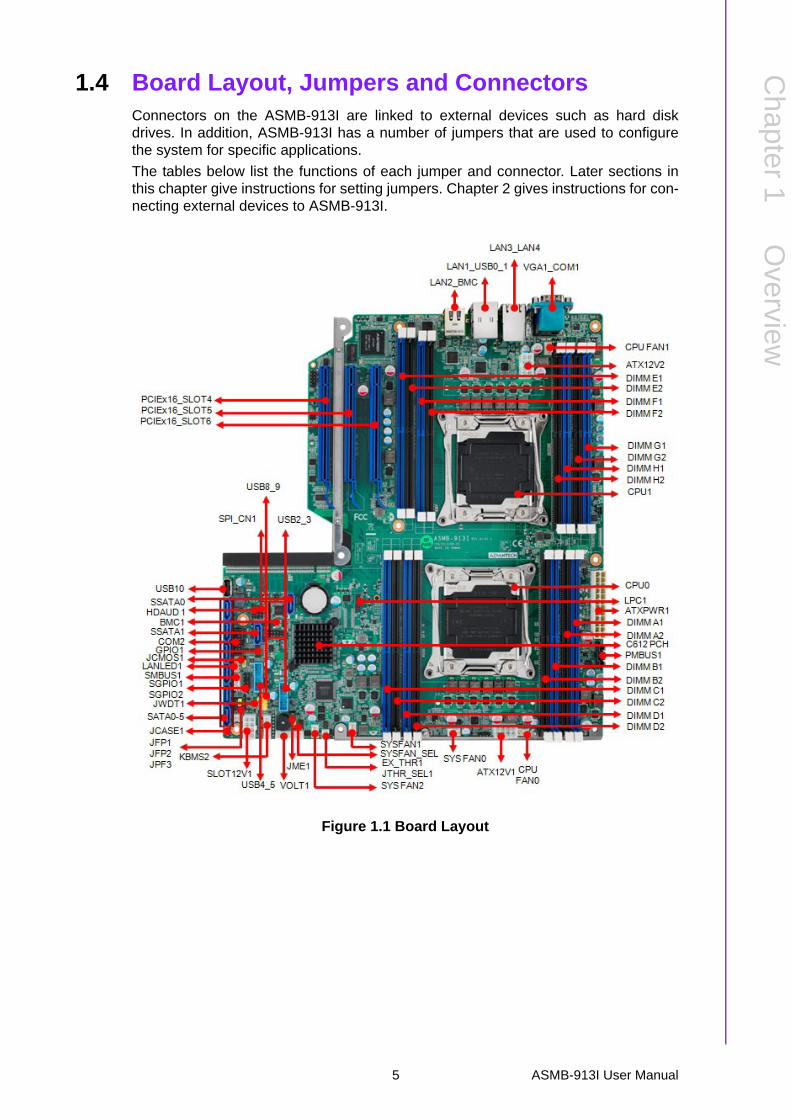
1.4 Board Layout, Jumpers and ConnectorsConnectors on the ASMB-913I are linked to external devices such as hard diskdrives. In addition, ASMB-913I has a number of jumpers that are used to configurethe system for specific applications.
The tables below list the functions of each jumper and connector. Later sections inthis chapter give instructions for setting jumpers. Chapter 2 gives instructions for con-necting external devices to ASMB-913I.
Figure 1.1 Board Layout
5 ASMB-913I User Manual
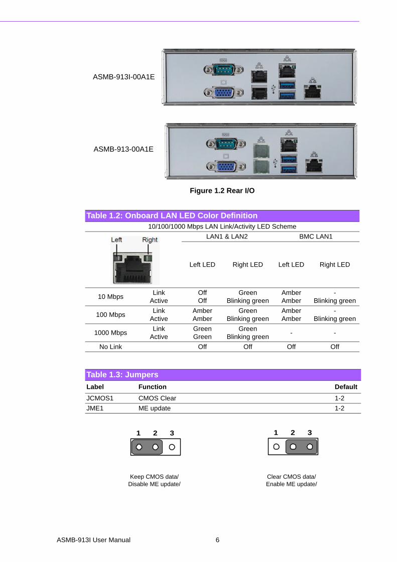
Figure 1.2 Rear I/O
Table 1.2: Onboard LAN LED Color Definition10/100/1000 Mbps LAN Link/Activity LED Scheme
LAN1 & LAN2 BMC LAN1
Left LED Right LED Left LED Right LED
10 MbpsLink
ActiveOff Off
GreenBlinking green
AmberAmber
-Blinking green
100 MbpsLink
ActiveAmberAmber
GreenBlinking green
AmberAmber
-Blinking green
1000 MbpsLink
ActiveGreenGreen
GreenBlinking green
- -
No Link Off Off Off Off
Table 1.3: Jumpers
Label Function Default
JCMOS1 CMOS Clear 1-2
JME1 ME update 1-2
Keep CMOS data/Disable ME update/
Clear CMOS data/Enable ME update/
ASMB-913I-00A1E
ASMB-913-00A1E
1 2 3 1 2 3
ASMB-913I User Manual 6

Chapter 1
Overview
Table 1.4: Connectors
Label Function
ATX12V1 SSI EPS 12 V auxiliary power connector (for CPU0) and memory
ATX12V2 SSI EPS 12 V auxiliary power connector (for CPU1) and memory
ATXPWR1 SSI EPS 24-pin main power connector (for system)
SLOT12V1 For PCIe slot 12 V input only
COM2 Serial port: RS-232
CPU0 Intel LGA2011 CPU0 socket
CPU1 Intel LGA2011 CPU1 socket
CPUFAN0 CPU0 fan connector (4-pin)
CPUFAN1 CPU1 fan connector (4-pin)
DIMMA0 Channel A1/A2 DIMM0 of CPU0
DIMMB0 Channel B1/B2 DIMM0 of CPU0
DIMMC0 Channel C1/C2 DIMM0 of CPU0
DIMMD0 Channel D1/D2 DIMM0 of CPU0
DIMME0 Channel E1/E2 DIMM0 of CPU1
DIMMF0 Channel F1/F2 DIMM0 of CPU1
DIMMG0 Channel G1/G2 DIMM0 of CPU1
DIMMH0 Channel H1/H2 DIMM0 of CPU1
JFP1/JFP2/JFP3 Front panel pin header connector
AUDIO1 HD audio Interface connector
BMC1 IPMI connector
LANLED1 LAN1 & LAN2 LED extension connector
LPC1 LPC port for debug & TPM module
EX_THR1 Connector for external thermistor
SPI_CN1 Connector for BIOS update tool
PCIE_PME1 PCIE x16 slot (For PME)
SLOT4 PCIE x16 slot
SLOT5 PCIE x16 slot
SLOT6 PCIE x16 slot
SLOT7 PCIE x16 slot
SYS FAN0 System fan connector (4-pin)
SYS FAN1 System fan connector (4-pin)
SYS FAN2 System fan connector (4-pin)
USB0_1, USB2_3, USB4_5
USB 3.0 port 0, 1; USB 3.0 port 2, 3, 4, 5 (20-pin header)
USB89 USB port 8, 9
USB10 USB port 10 (Type-A)
VOLT1 For Advantech alarm board usage
PMBUS1 Power supply SMBbus I2C Header
SATA_SGPIO_1 Supports Serial_Link interface for onboard SATA connections
GPIO1 GPIO function for customize usage
SMBUS1 For Advantech chassis usage
KBMS2 For additional keyboard/mouse
7 ASMB-913I User Manual

1.5 Block Diagram
Figure 1.3 Block Diagram
1.6 System MemoryASMB-913I has 16 288-pin memory slots for DDR4 1600/1866/2133 MHz memorymodules with maximum capacity of 512 GB (Maximum 32 GB for each DIMM).ASMB-913I supports registered DIMMs memory module.
Table 1.5: Onboard LED
LED Description LED Definition
5V_LED1 Power on LEDOff: Power off
On (Green): System is On
5VSB_LED1 Standby LEDOff: No input AC Power
On (Green): System is ON, in sleep mode, or in soft-off mode
LED3BMC heartbeat LED(ASMB-913I SKU Only)
Blinking (Green):Controller is working normally
ASMB-913I User Manual 8

Chapter 1
Overview
1.7 Memory Installation Procedures
Step 1
To install DIMMs, first make sure the two handles of the DIMM socket are in the
“open” position. i.e. The handles lean outward.
Single CPU Installed(CPU0)
1 2 3 4 5 6 7 8 Quantity of memory installed
DIMMA1 V V V V V V V V
DIMMB1 V V V V V V V
DIMMC1 V V V V V V
DIMMD1 V V V V V
DIMMA2 V V V V
DIMMB2 V V V
DIMMC2 V V
DIMMD2 V
Dual CPU Installed(CPU0 & CPU1)
2 4 6 8 10 12 14 16 Quantity of memory installed
DIMMA1DIMME1
V V V V V V V V
DIMMB1DIMMF1
V V V V V V V
DIMMC1DIMMG1
V V V V V V
DIMMD1DIMMH2
V V V V V
DIMMA2DIMME2
V V V V
DIMMB2DIMMF2
V V V
DIMMC2DIMMG2
V V
DIMMD2DIMMH2
V
9 ASMB-913I User Manual
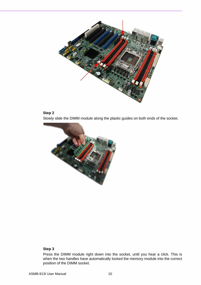
Step 2
Slowly slide the DIMM module along the plastic guides on both ends of the socket,
Step 3
Press the DIMM module right down into the socket, until you hear a click. This iswhen the two handles have automatically locked the memory module into the correctposition of the DIMM socket.
ASMB-913I User Manual 10
Chapter 1
Overview
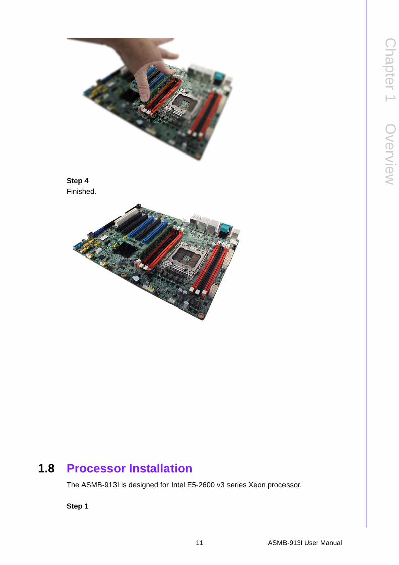
Step 4
Finished.
1.8 Processor InstallationThe ASMB-913I is designed for Intel E5-2600 v3 series Xeon processor.
Step 1
11 ASMB-913I User Manual

Press the first lever and move it sideways slightly until it is released from the reten-tion tab.
Step 2
Press the other lever and move it sideways slightly until it is also released from theretention tab.
ASMB-913I User Manual 12

Chapter 1
Overview
Step 3
Lift the load plate.
Step 4
Position the CPU over the socket ensuring that the triangle mark on the CPU lines upwith the triangle mark on the motherboard.
Step 5
Remove protective plastic cover.
Triangle mark
CPU
13 ASMB-913I User Manual

Step 6
Close the load plate over the CPU.
Step 7
Push down both levers and insert them under the retention tabs ensuring the edge ofthe load plate is fixed securely by both levers.
Step 8
Finished.
ASMB-913I User Manual 14

Chapter2
2 Connections
2.1 IntroductionYou can access most of the connectors from the top of the board as it is beinginstalled in the chassis. If you have a number of cards installed, you may need to par-tially remove a card to make all the connections.
2.2 USB Ports and LAN Ports (USB0~USB10/LAN1/LAN2/LAN3/LAN4)The USB ports comply with USB 2.0 & 3.0. Transmission rates could be up to 480Mbps (USB 2.0) / 5Gbps (USB 3.0) and fuse protection are supported. The USBinterface can be disabled in the system BIOS setup.
The ASMB-913I is equipped with four high-performance 1000 Mbps Ethernet LANs.They are supported by all major network operating systems. The RJ-45 jacks on therear plate provide convenient 1000Base-T operation.
Example: USB89
USB2_3, USB4_5
LAB3_LAN42
ASMB-913I User Manual 16

Chapter 2
Connections
2.3 VGA ConnectorThe ASMB-913I includes a VGA interface that can drive conventional CRT and LCDdisplays.
2.4 Serial Ports (COM1/COM2)The ASMB-913I offers 2 serial ports (One on the rear panel and one onboard).
COM2
17 ASMB-913I User Manual

2.5 PS2 Keyboard and Mouse Header (KBMS2)KBMS2 connector is for additional keyboard & mouse device usage.
2.6 CPU Fan Connector (CPU FAN0/FAN1)If a fan is used, this connector supports cooling fans that draw up to 500 mA (6 W).
KBMS2
ASMB-913I User Manual 18

Chapter 2
Connections
2.7 System Fan Connector (SYS FAN0/FAN1/FAN2)
Table 2.1: CPU FAN Pin DefinitionCPU FAN0 CPU FAN1
1 GND GND
2 +12V +12V
3 CPU0_TACH CPU1_TACH
4 CPU0_PWM CPU1_PWM
Table 2.2: SYS FAN Pin Definition
SYS FAN0 SYS FAN1 SYS FAN2
1 GND GND GND
2 +12V +12V +12V
3 FAN0_TACH FAN1_TACH FAN2_TACH
4 FAN0_PWM FAN1_PWM FAN2_PWM
19 ASMB-913I User Manual

2.8 Front Panel Connector (JFP1)There are several external switches and LEDs to monitor and control the ASMB-913I.
2.8.1 Power LED (JFP3)JFP3 pin 1 and pin 3 are for the power LED. Refer to Appendix B for detailed infor-mation on the pin assignments. If an ATX power supply is used, the system’s powerLED status will be as indicated as follows.
2.8.2 External Speaker (JFP2 pins 1, 4, 7, 10)JFP2 pins 1, 4, 7, 10 connect to an external speaker. The ASMB-913I provides anonboard buzzer as an alternative. To enable the buzzer, set pins 7-10 closed.
Table 2.3: ATX Power Supply LED Status
ACPI Power Mode LED (ATX power)
System On (S0) On
System Standby (S1) Fast flashes
System Hibernation(S4) Slow flashes
System Off (S5) Off
1 2 3+ -
1 4 7 10+ -
ASMB-913I User Manual 20

Chapter 2
Connections
2.8.3 HDD LED Connector (JFP1 Pins 2 & 5)You can connect an LED to connector JFP1 to indicate when the HDD is active.
2.8.4 Reset Connector (JFP1 Pins 9 & 12)Many computer cases offer the convenience of a reset button.
2.8.5 SNMP Connector (JFP1 Pins 8 & 11)SNMP connector could connect with “SAB-2000” remote control board to monitorASMB-913I through the super IO chip.
2.8.6 Case Open (JCASE1)A Chassis Intrusion header is located at JCASE1 on the motherboard. Attach theappropriate cable from the chassis to be informed of a chassis intrusion when thechassis is opened. The default function is disabled and Pin 1-2 is bridged by a jumpercap.
2 5 +
9 12
8 11(Data) (CLK)
1
2
21 ASMB-913I User Manual

2.9 SATA SGPIO (SATA_SGPIO_1)
1 SCLOCK_PCH
2 NC
3 SLOAD_PCH
4 SDATAOUT0_PCH
5 SDATAOUT1_PCH
ASMB-913I User Manual 22
Chapter 2
Connections
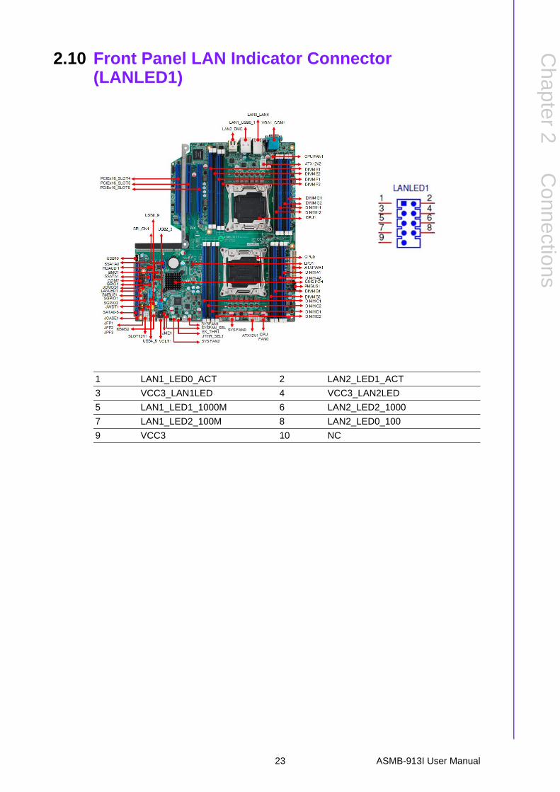
2.10 Front Panel LAN Indicator Connector (LANLED1)
1 LAN1_LED0_ACT 2 LAN2_LED1_ACT
3 VCC3_LAN1LED 4 VCC3_LAN2LED
5 LAN1_LED1_1000M 6 LAN2_LED2_1000
7 LAN1_LED2_100M 8 LAN2_LED0_100
9 VCC3 10 NC
23 ASMB-913I User Manual

2.11 Serial ATA Interface (SATA0-SATA5, sSATA0-sSATA1)ASMB-913I features ten serial ATA III interfaces (up to 600 MB/s) which easescabling to hard drives with thin and long cables.
ASMB-913I User Manual 24

Chapter 2
Connections
2.12 PCIe & PCI Expansion SlotsThe ASMB-913I provides three and PME expansion slots.
Slot Length Link PCI-E Generation PCIe link provide from
SLOT4 PCI-E x16 PCI-E x16 3 CPU1
SLOT5 PCI-E x16 PCI-E x16 3 CPU1
SLOT6 PCI-E x16 PCI-E x16 3 CPU0
SLOT PME PCI-E x16 PCI-E x16 3 CPU0
25 ASMB-913I User Manual

2.13 Auxiliary Power Connector (ATXPWR1/ATX12V1/ATX12V2)
Note! 1. Please use a power supply which is of SSI type; minimum output should be at least 800 W.
2. ATXPWR1 & ATX12V1 & ATX12V2 sockets should be all con-nected with power supply, otherwise ASMB-913I will not boot up normally.
ASMB-913I User Manual 26

Chapter 2
Connections
2.14 HD Audio Interface Connector (AUDIO1)
1 +5 V_AUD 2 GND
3 ACZ_SYNC 4 ACZ_BITCLK
5 ACZ_SDOUT 6 ACZ_SDIN0
7 ACZ_SDIN1 8 ACZ_RST#
9 +AC_12V 10 GND
11 GND 12 NC
27 ASMB-913I User Manual
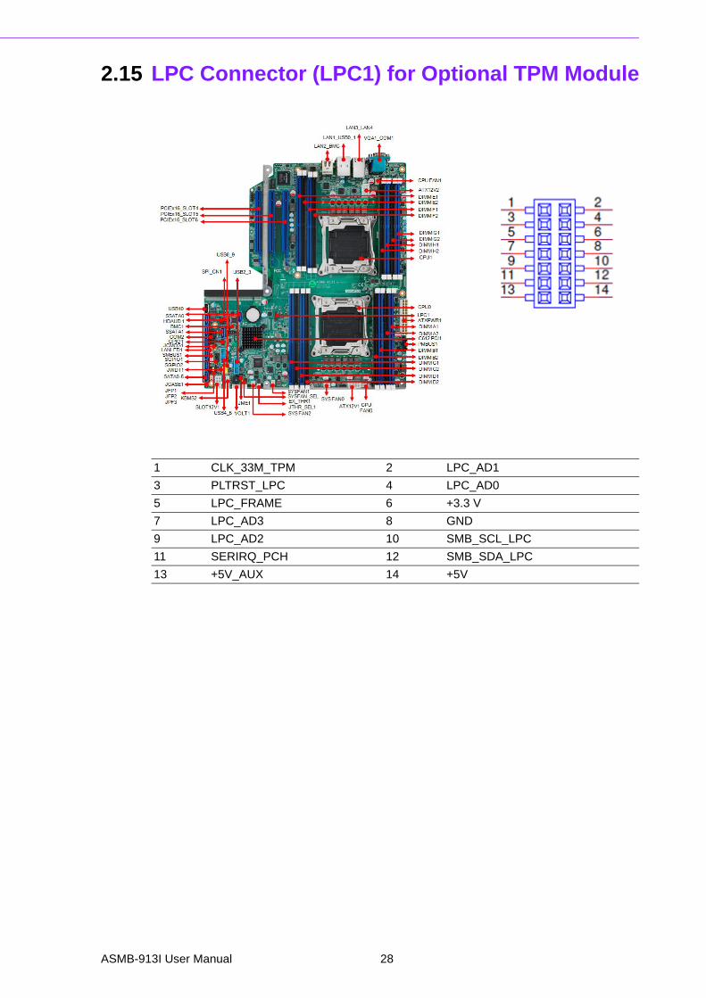
2.15 LPC Connector (LPC1) for Optional TPM Module
1 CLK_33M_TPM 2 LPC_AD1
3 PLTRST_LPC 4 LPC_AD0
5 LPC_FRAME 6 +3.3 V
7 LPC_AD3 8 GND
9 LPC_AD2 10 SMB_SCL_LPC
11 SERIRQ_PCH 12 SMB_SDA_LPC
13 +5V_AUX 14 +5V
ASMB-913I User Manual 28

Chapter 2
Connections
2.16 Clear CMOS Connector (JCMOS1)Setting jumper from pin 1-2 to pin 2-3,then back to pin 1-2 to reset CMOS data.
2.17 PMBUS Connector (PMBUS1)
JCMOS1 JME1
1 SRTC_RST_PCH NC
2 RTC_RST_PCH HDA_SDOUT_PCH
3 GND 3.3V
29 ASMB-913I User Manual

2.18 Front Panel SMBUS Connector (SMBUS1)
1 SMB_SCL_PM
2 SMB_SDA_PM
3 SMB_ALT_PM
4 GND
5 +3.3V
1 +3.3V_AUX
2 SMB_SCL_FRU
3 SMB_SDA_FRU
4 GND
ASMB-913I User Manual 30

Chapter 2
Connections
2.19 IPMI Module Connector (BMC1)
This connector will only fit to ASMB-BMC-00A1E and only exist in ASMB-913I sku.
IPMI1
31 ASMB-913I User Manual

2.20 VOLT1 Connector
VOLT1 connects to the alarm board on the Advantech chassis. These alarm boardsgive warnings if a power supply or fan fails, if the chassis overheats, or if the back-plane malfunctions.
1 5VSB 5 +5V
2 GND 6 +3.3V
3 GND 7 -12V
4 -5V 8 +12V
ASMB-913I User Manual 32

Chapter 2
Connections
2.21 GPIO Connector
1 SIO_GPIO0 2 SIO_GPIO4
3 SIO_GPIO1 4 SIO_GPIO5
5 SIO_GPIO2 6 SIO_GPIO6
7 SIO_GPIO3 8 SIO_GPIO7
9 VCC_GPIO0 10 GND
33 ASMB-913I User Manual

ASMB-913I User Manual 34

Chapter 3
3 AMI BIOS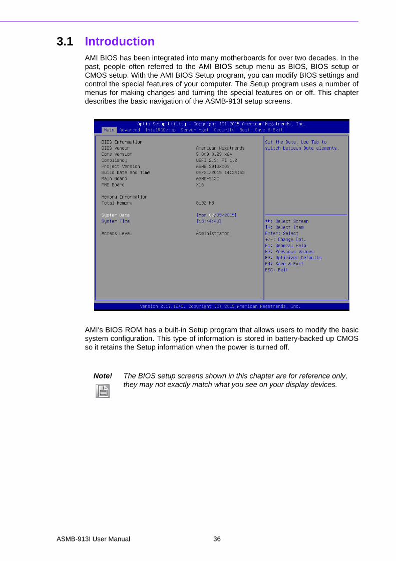
3.1 IntroductionAMI BIOS has been integrated into many motherboards for over two decades. In thepast, people often referred to the AMI BIOS setup menu as BIOS, BIOS setup orCMOS setup. With the AMI BIOS Setup program, you can modify BIOS settings andcontrol the special features of your computer. The Setup program uses a number ofmenus for making changes and turning the special features on or off. This chapterdescribes the basic navigation of the ASMB-913I setup screens.
AMI's BIOS ROM has a built-in Setup program that allows users to modify the basicsystem configuration. This type of information is stored in battery-backed up CMOSso it retains the Setup information when the power is turned off.
Note! The BIOS setup screens shown in this chapter are for reference only, they may not exactly match what you see on your display devices.
ASMB-913I User Manual 36
Chapter 3
AM
I BIO
S
3.2 BIOS Setup
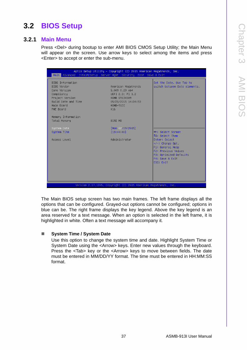
3.2.1 Main MenuPress <Del> during bootup to enter AMI BIOS CMOS Setup Utility; the Main Menuwill appear on the screen. Use arrow keys to select among the items and press<Enter> to accept or enter the sub-menu.
The Main BIOS setup screen has two main frames. The left frame displays all theoptions that can be configured. Grayed-out options cannot be configured; options inblue can be. The right frame displays the key legend. Above the key legend is anarea reserved for a text message. When an option is selected in the left frame, it ishighlighted in white. Often a text message will accompany it.
System Time / System DateUse this option to change the system time and date. Highlight System Time orSystem Date using the <Arrow> keys. Enter new values through the keyboard.Press the <Tab> key or the <Arrow> keys to move between fields. The datemust be entered in MM/DD/YY format. The time must be entered in HH:MM:SSformat.
37 ASMB-913I User Manual
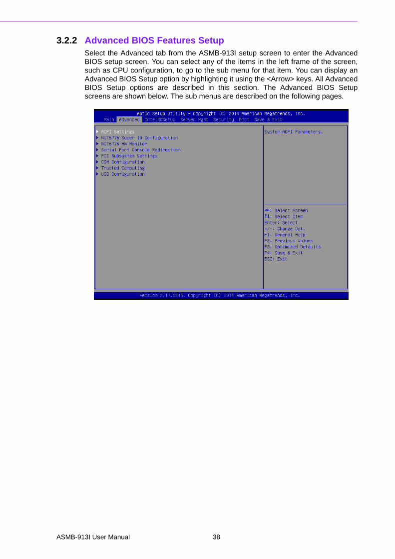
3.2.2 Advanced BIOS Features SetupSelect the Advanced tab from the ASMB-913I setup screen to enter the AdvancedBIOS setup screen. You can select any of the items in the left frame of the screen,such as CPU configuration, to go to the sub menu for that item. You can display anAdvanced BIOS Setup option by highlighting it using the <Arrow> keys. All AdvancedBIOS Setup options are described in this section. The Advanced BIOS Setupscreens are shown below. The sub menus are described on the following pages.
ASMB-913I User Manual 38

Chapter 3
AM
I BIO
S
3.2.2.1 ACPI Settings
Enable Hibernation"Enable or disable" Hibernation.
Lock Legacy Resources"Enable" or "Disable" Lock Legacy Resources.
39 ASMB-913I User Manual

3.2.2.2 NCT6776 Super IO Configuration
Serial Port 1 Configuration
– Serial Port"Enable" or "Disable" Serial Port 1.
– Change SettingsTo select an optimal setting for serial port 1.
ASMB-913I User Manual 40

Chapter 3
AM
I BIO
S
Serial Port 2 Configuration
– Serial Port"Enable" or "Disable" Serial Port 2.
– Change SettingsTo select an optimal setting for serial port 2.
41 ASMB-913I User Manual

3.2.2.3 NCT6776 HW Monitor
Case Open WarningEnable/Disable the Chassis Intrusion monitoring function. When enabled and
the case is opened, the warning message will show in POST screen.
Watchdog TimerEnable and Disable the watchdog timer function.
CPU Warning TemperatureSet the CPU warning temperature threshold. When the system reaches the
warning temperature, the speaker will beep.
ACPI Shutdown TemperatureSet the ACPI shutdown temperature threshold. When the system reaches the
shutdown temperature, it will be automatically shut down by ACPI OS to protect
the system from overheat damage.
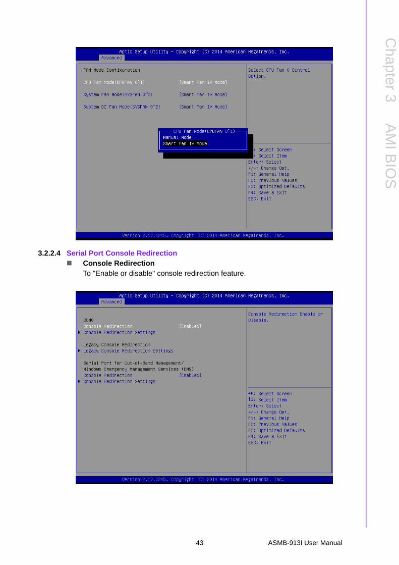
Fan Mode ConfigurationWhen set to manual mode, fan duty setting can be changed; the range is from
30%~100%, default setting is 50%.
ASMB-913I User Manual 42
Chapter 3
AM
I BIO
S
3.2.2.4 Serial Port Console Redirection Console Redirection
To "Enable or disable" console redirection feature.
43 ASMB-913I User Manual

Console Redirection Settings
– Terminal TypeSelect a terminal type to be used for console redirection.
Options available: VT100/VT100+/ANSI /VT-UTF8.
– Bits Per SecondSelect the baud rate for console redirection.
Options available: 9600/19200/57600/115200.
– ParityA parity bit can be sent with the data bits to detect some transmission errors.
Even: parity bit is 0 if the number of 1's in the data bits is even.
Odd: parity bit is 0 if number of 1's the data bits is odd.
Mark: parity bit is always 1. Space: Parity bit is always 0.
Mark and Space Parity do not allow for error detection.
Options available: None/Even/Odd/Mark/Space.
– Stop BitsStop bits indicate the end of a serial data packet. (A start bit indicates thebeginning). The standard setting is 1 stop bit. Communication with slowdevices may require more than 1 stop bit.
Options available: 1/2.
– Flow ControlFlow control can prevent data loss from buffer overflow. When sending data,if the receiving buffers are full, a 'stop' signal can be sent to stop the dataflow. Once the buffers are empty, a 'start' signal can be sent to re-start theflow. Hardware flow control uses two wires to send start/stop signals.
Options available: None/Hardware RTS/CTS.
– Recorder Mode
ASMB-913I User Manual 44

Chapter 3
AM
I BIO
S
When this mode enabled, only text will be send. This is to capture Terminaldata.
Options available: Enabled/Disabled.
– Legacy OS Redirection ResolutionOn Legacy OS, the number of Rows and Columns supported redirection.
Options available: 80x24/80X25.
– Putty KeypadSelect function key and keypad on putty.
Console Redirection Setting
– Out-of-Band Mgmt PortTo select the com port user would like to set for having console redirectionfeature.
– Terminal TypeSet as "VT100", "VT100+", "VT-UTF8", or "ANSI". "VT-UTF8" is the defaultsetting.
– Bits Per SecondTo select serial port transmission. Speed must be matched on the other side.It can be set as "9600", "19200", "57600", or "115200". "115200" is thedefault setting.
– Flow ControlFlow control can prevent data loss from buffer overflow. It can be set as"None",
"Hardware RTS/CTS", or "Software Xon/Xoff". "None" is the default setting.
45 ASMB-913I User Manual

3.2.2.5 PCI Subsystem Settings
PCI / PCI-X Latency TimerValue in units of PCI clocks for PCI device latency timer register.
Above 4G DecodingEnables or disables 64-bit capability. Devices to be decoded in above 4G
address space (Only if system supports 64-bit PCI decoding).
Note! There are some graphic or GPU card need to enable 4G Decoding.
ASMB-913I User Manual 46

Chapter 3
AM
I BIO
S
3.2.2.6 CSM Configuration
CSM SupportEnables or disables UEFI CSM (Compatibility Support Module) to support a leg-acy PC boot process.
GateA20 ActiveThis items is useful When RT code is executed above 1MB. When this it's set as
"UPON RQUEST", GA20 can be disabled using BIOS services. When it's set as
"Always", it does not allow disabling GA20.
Option ROM Messages"Force BIOS or Keep Current" to set the display mode for Option ROM
47 ASMB-913I User Manual

3.2.2.7 Trusted Computing
Security Device SupportEnables or disables BIOS support for security device.
Purchase Advantech LPC TPM module to enable TPM function. P/N: PCATPM-
00A1E.
ASMB-913I User Manual 48

Chapter 3
AM
I BIO
S
3.2.2.8 USB Configuration
Legacy USB SupportThis is for supporting USB device under a legacy OS such as DOS. Whenchoosing "AUTO", the system will automatically detect if any USB device isplugged into the computer and enable USB legacy mode when a USB device is
plugged and disable USB legacy mode when no USB device is attached.
XHCI Hand-offThis is a workaround for OS without XHCI hand-off support.
The XHCI ownership change should be claimed by XHCI driver.
EHCI Hand-offThis is a workaround for OS without EHCI hand-off support.
The EHCI ownership change should be claimed by EHCI driver.
USB Mass Storage Driver SupportEnable/Disable USB mass storage driver support.
USB Transfer Time-outSelects the USB transfer time-out value. [1,5,10,20sec]
Device Reset Time-outSelects the USB device reset time-out value. [10,20,30,40 sec]
Device Power-up DelayThis item appears only when Device power-up delay item is set to [manual].
49 ASMB-913I User Manual

3.2.3 IntelRCSetup
3.2.3.1 Processor Configuration
ASMB-913I User Manual 50

Chapter 3
AM
I BIO
S
Per-Socket ConfigurationUse this to select how many processor cores you want to activate when you are
using a dual or quad core processor.
Hyper-threadingEnable or disable Intel Hyper Threading technology.
Execute Disable BitThis item specifies the Execute Disable Bit Feature. The settings are Enabledand Disabled. The Optimal and Fail-Safe default setting is Enabled. If Disabledis selected, the BIOS forces the XD feature flag to always return to 0.
VMXEnable or disable Intel Virtual Machine Extensions (VMX) for IA-32 processorsthat support Intel® Vanderpool Technology
SMXEnable or disable the Safer Mode Extensions. Safer Mode Extensions (SMX)provide a means for system software to launch an MLE and establish a mea-sured environment within the platform to support trust decisions by end users.
Hardware PrefetcherHardware Prefetcher is a technique that fetches instructions and/or data frommemory into the CPU cache memory well before the CPU needs it, so that it canimprove the load-to-use latency. You may choose to enable or disable it.
Adjacent Cache Line PrefetchThe Adjacent Cache-Line Prefetch mechanism, like automatic hardwareprefetch, operates without programmer intervention. When enabled through theBIOS, two 64-byte cache lines are fetched into a 128-byte sector, regardless ofwhether the additional cache line has been requested or not. You may choose toenable or disable it.
51 ASMB-913I User Manual

DCU Streamer PrefetcherEnable prefetch of next L1 data line based upon multiple loads in same cacheline.
DCU IP PrefetcherEnable prefetch of next L1 line based upon sequential load history.
DCU ModeChange the data cache unit (DCU) mode.
AES-NIThis item is to enable or disable CPU advanced encryption standard instruc-tions.
3.2.3.2 Advanced Power Management
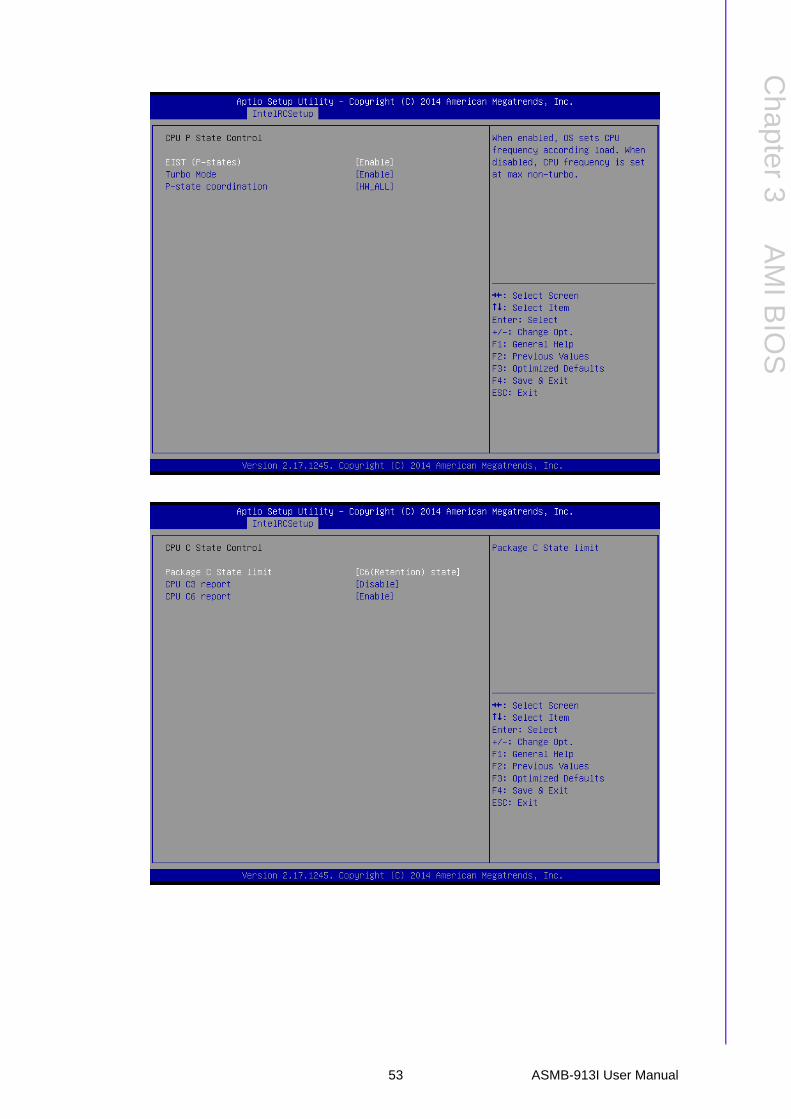
Power TechnologyPower technology default is "Energy Efficient". User can set "EIST", "P-STATE","C3", "C6", "Package C State limit" under "Custom"
Mode.
ASMB-913I User Manual 52
Chapter 3
AM
I BIO
S
53 ASMB-913I User Manual
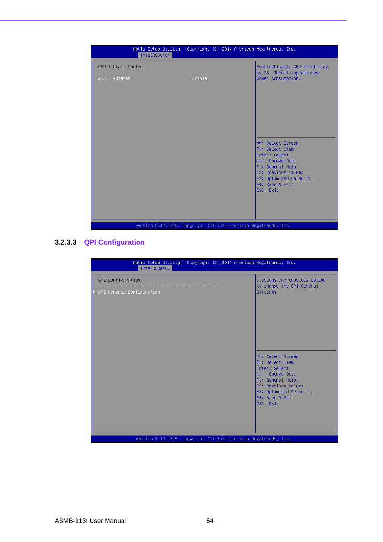
3.2.3.3 QPI Configuration
ASMB-913I User Manual 54

Chapter 3
AM
I BIO
S
QPI Speed ModeSelect the QPI link speed as either the Fast mode or Slow Mode.
QPI Frequency SelectAllows for selecting the QPI Link frequency.
QPI Link0pEnable/Disable QPI Link0p.
QPI Link1Enable/Disable QPI Link1.
COD enableEnable/Disable Cluster on Die.
Early SnoopEnable/Disable Early Snoop.
55 ASMB-913I User Manual

Note! 1. Intel® recommends exposing all 3 snoop modes as BIOS options to the user due to the varying memory latency & bandwidth trad-eoffs across SKUs for each snoop mode.a). Intel® Xeon® Processor E5-2600 v3 Product Family supports up to 3 different snoop modes (Early Snoop, Home Snoop, Cluster on Die) to maintain memory coherency across the 2 sockets.b). Choosing the optimal snoop mode setting is dependent on the workload characteristics and the SKU that is used.
2. It is expected behavior for LCC SKUs (4-8 cores) in NUMA & Early Snoop mode to have low remote bandwidth.a). For workloads on LCC SKUs that need high local & remote memory bandwidth, use NUMA & Home Snoop mode at the expense of higher memory latency (up to 1.07x).b). For workloads on LCC SKUs that have mostly remote memory accesses, use UMA & either Early Snoop or Home Snoop mode.
Snoop Mode Configuration
Cluster on Die Enable
Early Snoop Mode
Early Snoop (ES)
Disable Enable
Auto Auto
Auto Enable
Disable Auto
Home Snoop (HS)Disable Disable
Auto Disable
Cluster on Die (COD)Enable Disable
Enable Auto
Not Supported - Invalid Settings
Enable Enable
ASMB-913I User Manual 56

Chapter 3
AM
I BIO
S
3.2.3.4 Memory Configuration
Data ScrabblingEnable/Disable Data Scrambling.
NumaEnable/Disable non uniform memory access (NUMA).
Memory TechnologyDisplay memory topology with DIMM population information.
57 ASMB-913I User Manual

3.2.3.5 IIO Configuration
CPU0/CPU1 PCIe ConfigurationPCIe port bifurcation control and select target link speed as Gen1, Gen2, Gen3.
PCI-E ASPM SupportThis item is to set the ASPM level. [Auto]: BIOS auto configure; [Force L0s]:Force all links to L0s state; [Disable]: To disable ASPM. Extended Synch If thisitem is [Enable], it allows generation of extended synchronization patterns..
VGA PriorityDetermines priority between onboard and 1st off-board video device found.
Primary Display AdaptorManually select display device from which PCIe slot
ASMB-913I User Manual 58

Chapter 3
AM
I BIO
S
59 ASMB-913I User Manual
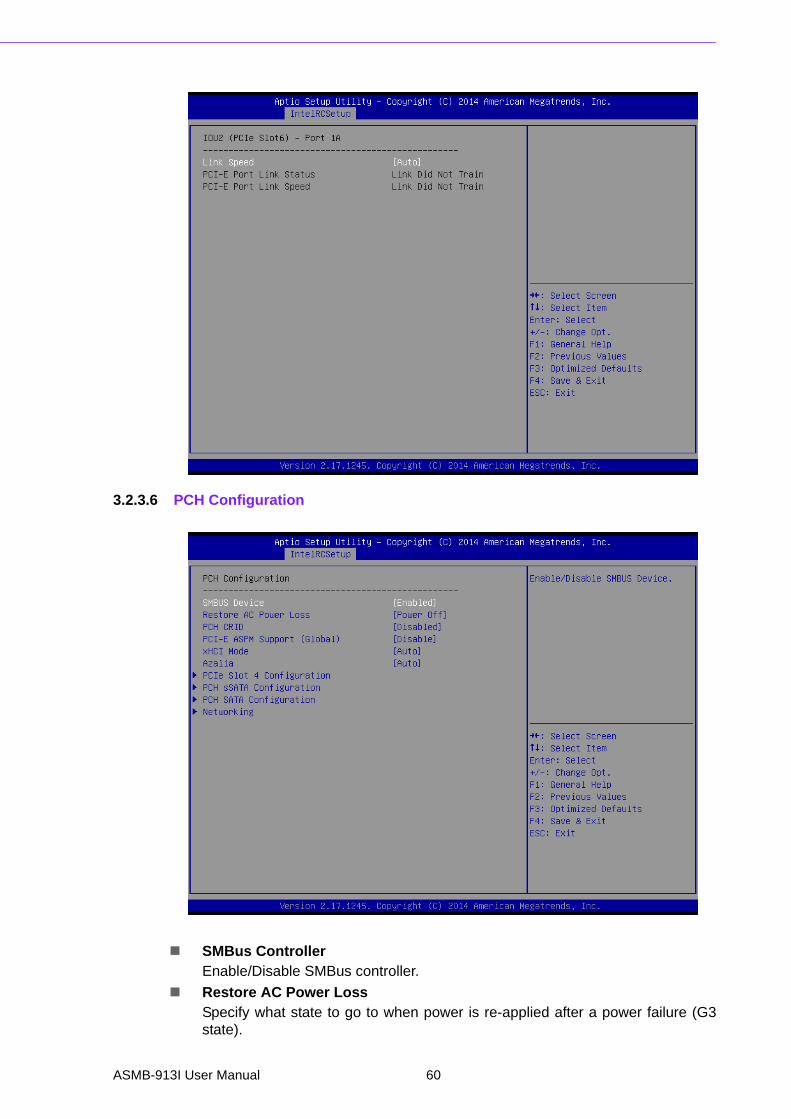
3.2.3.6 PCH Configuration
SMBus ControllerEnable/Disable SMBus controller.
Restore AC Power LossSpecify what state to go to when power is re-applied after a power failure (G3state).
ASMB-913I User Manual 60

Chapter 3
AM
I BIO
S
PCH Compatibility RIDEnable/Disable PCH Compatibility Revision ID (CRID) Functionality.
PCI-E ASPM SupportTo set ASPM level for PCI Express.
XHCI ModeMode of operation of XHCI controller.
Azalia HD AudioEnable/Disable Azalia HD audio function.
PCIe Slot 4 ConfigurationTo enable or disable PCI Express Slot 4 and select target link speed as Gen1,Gen2.
PCH SATA and sSATA Configuration
61 ASMB-913I User Manual
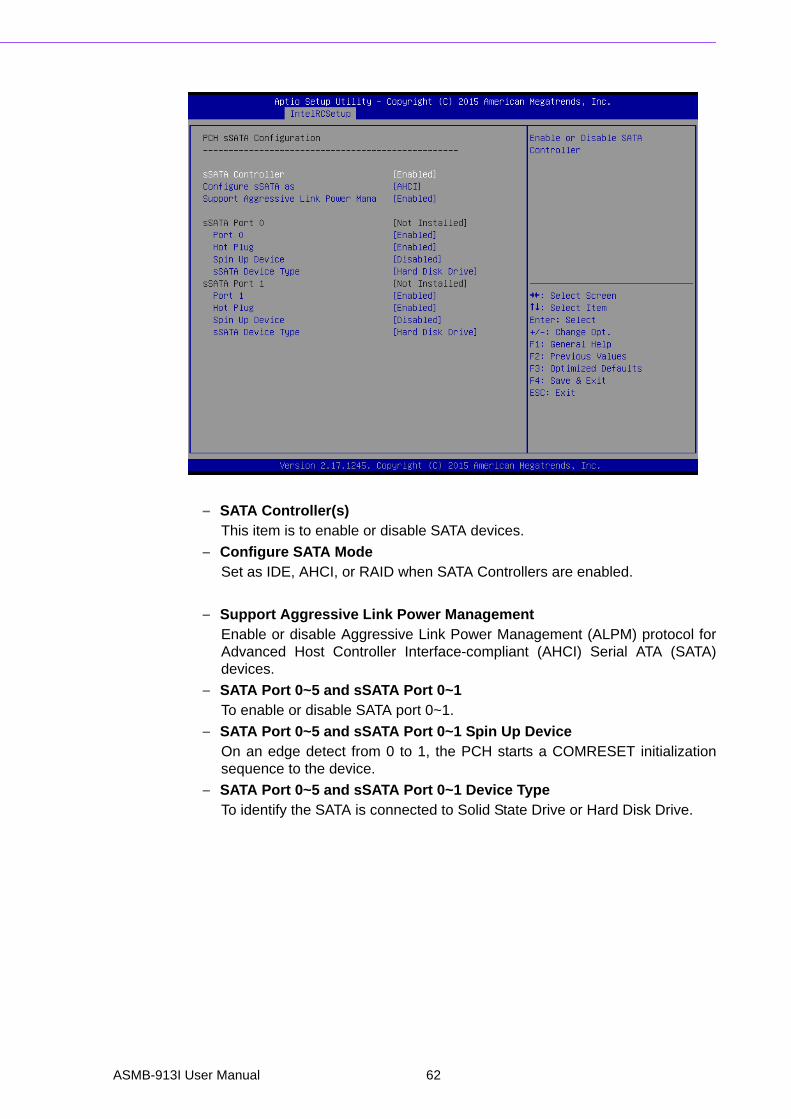
– SATA Controller(s)This item is to enable or disable SATA devices.
– Configure SATA Mode Set as IDE, AHCI, or RAID when SATA Controllers are enabled.
– Support Aggressive Link Power ManagementEnable or disable Aggressive Link Power Management (ALPM) protocol forAdvanced Host Controller Interface-compliant (AHCI) Serial ATA (SATA)devices.
– SATA Port 0~5 and sSATA Port 0~1To enable or disable SATA port 0~1.
– SATA Port 0~5 and sSATA Port 0~1 Spin Up DeviceOn an edge detect from 0 to 1, the PCH starts a COMRESET initializationsequence to the device.
– SATA Port 0~5 and sSATA Port 0~1 Device TypeTo identify the SATA is connected to Solid State Drive or Hard Disk Drive.
ASMB-913I User Manual 62

Chapter 3
AM
I BIO
S
Networking
– LAN1 ControllerEnable/Disable Intel I210 Controller support.
– LAN1 PXE OpROMEnable/Disable Boot option for Intel I210 controller.
– LAN2 ControllerEnable/Disable Intel I210 Controller support.
– LAN2 PXE OpROMEnable/Disable Boot option for Intel I210 controller.
– LAN3 ControllerEnable/Disable Intel I210 Controller support.
– LAN3 PXE OpROMEnable/Disable Boot option for Intel I210 controller.
– LAN4 ControllerEnable/Disable Intel I210 Controller support.
– LAN4 PXE OpROMEnable/Disable Boot option for Intel I210 controller.
63 ASMB-913I User Manual

3.2.3.7 Server ME Configuration
This page shows the Server ME configuration
ASMB-913I User Manual 64

Chapter 3
AM
I BIO
S
3.2.4 Server Management
BMC SupportEnable/Disable interfaces to communicate with BMC
Wait for BMCIf enabled, motherboard will wait 30 ~ 60 seconds until BMC module boots up
completely. After that, the normal BIOS post screen will be displayed.
If disabled, motherboard will not wait for BMC module's response.
Wait for BMC counterWait for BMC counter for initialize host to BMC interfaces.
The MB beep per 5 seconds to check it.
3.2.4.1 System Event Log SEL Components
Enable/Disable all features of system event logging during boot.
Erase SELChoose options for erasing SEL.
When SEL is FullChoose options for reactions to a full SEL.
Log EFI Status CodesDisable the logging of EFI status codes or log only error code or only progress
code or both.
3.2.4.2 BMC Self Test Log Erase Log
Erase log options.
When Log is FullSelect the action to be taken when log is full.
65 ASMB-913I User Manual

3.2.4.3 BMC Network Configuration Configuration Address Source
Select to configure LAN channel parameters statically or dynamically (by BMC).
Unspecified option will not modify any BMC network parameters during BIOS
phase.
3.2.5 Security
Note! With AC power & Battery. Short CMOS1 Jumper:
Date/Time & Password: Keep
Setting: reset to default
AC power and CMOS battery are removed. Short CMOS1 Jumper:
Date/Time: reset to default
Password: Keep
Setting: reset to default
ASMB-913I User Manual 66
Chapter 3
AM
I BIO
S
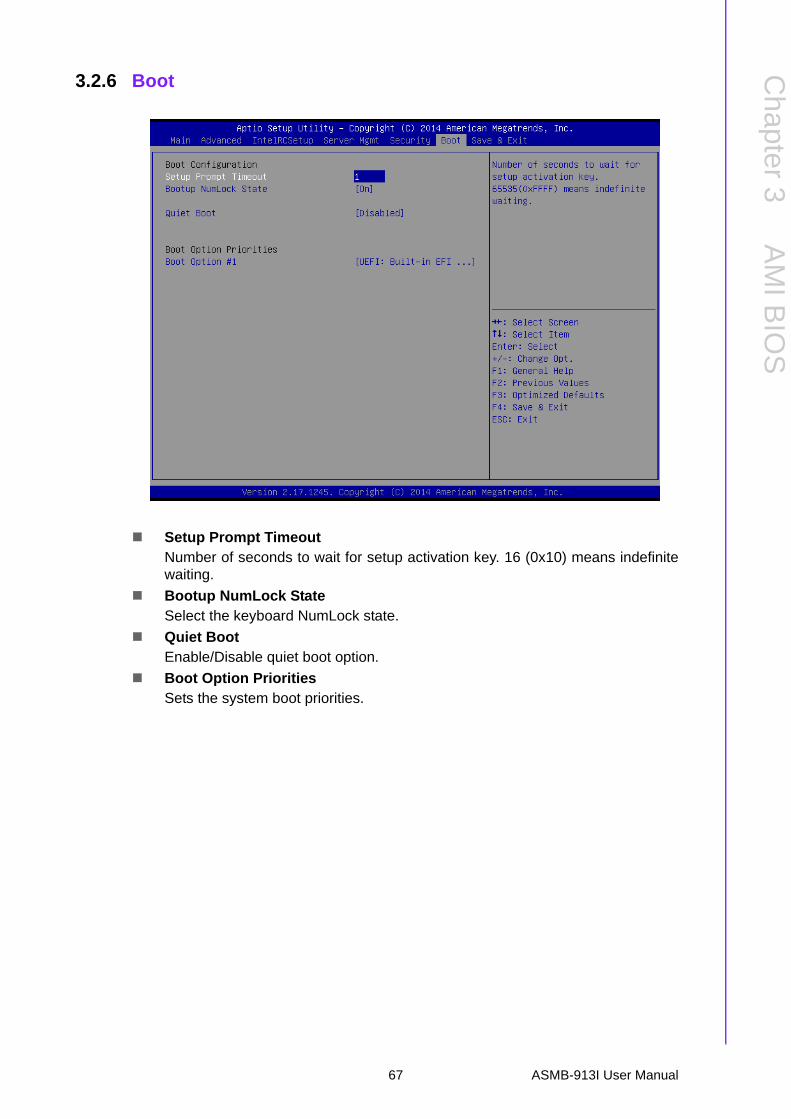
3.2.6 Boot
Setup Prompt TimeoutNumber of seconds to wait for setup activation key. 16 (0x10) means indefinitewaiting.
Bootup NumLock StateSelect the keyboard NumLock state.
Quiet BootEnable/Disable quiet boot option.
Boot Option PrioritiesSets the system boot priorities.
67 ASMB-913I User Manual

3.2.7 Save & Exit
Save Changes and ExitExit system setup after saving the changes.
Discard Changes and ExitExit system setup without saving any changes.
Save Changes and ResetReset the system after saving changes.
Discard Changes and ResetReset system setup without saving any changes.
Save ChangesSave changes done so far to any of the setup options.
Discard ChangesDiscard changes done so far to any of the setup options.
Restore DefaultsRestore/Load default values for all the setup options.
Save as User DefaultsSave the changes done so far as user defaults.
Restore User DefaultsRestore the user defaults to all the setup options.
ASMB-913I User Manual 68

Chapter 4
4 Chipset Software Installation Utility
4.1 Before BeginningTo facilitate the installation of the enhanced display drivers and utility software, readthe instructions in this chapter carefully. The drivers for the ASMB-913I are locatedon the software installation CD.
Before beginning, it is important to note that most display drivers need to have therelevant software application already installed on the system prior to installing theenhanced display drivers. In addition, many of the installation procedures assumethat you are familiar with both the relevant software applications and operating sys-tem commands. Review the relevant operating system commands and the pertinentsections of your application software’s user manual before performing the installa-tion.
4.2 Introduction
4.2.1 Main MenuThe Intel Chipset Software Installation (CSI) utility installs the Windows INF files thatoutline to the operating system how the chipset components will be configured. Thisis needed for the proper functioning of the following features:
Core PCI PnP services Serial ATA interface support USB 1.1/2.0 support (USB 2.0 driver needs to be installed separately for Win-
dows 98) Identification of Intel chipset components in the Device Manager
Note! The files on the software installation CD are compressed. Do not attempt to install the drivers by copying the files manually. You must use the supplied SETUP program to install the drivers.
Note! The chipset driver is used for the following versions of Windows, and it has to be installed before installing all the other drivers:
Windows Server 2012 R2 Standard
Windows Server 2008 Enterprise Edition R2(SP1)
Windows 7(Ultimate SP1)
Windows 8.1 Ultimate
x64
x64
x86 & x64
x86 & x64
Note! It is necessary to update all the latest Microsoft hotfix files when using this OS.
ASMB-913I User Manual 70

Chapter 4
ChipsetS
oftware
Installation Utility
4.3 Windows 7 & 8/ Windows server 2008 & 20121. Insert the driver CD into your system's CD-ROM drive. When the folder is dis-
played, move the mouse cursor over the folder "01_Intel INF". Find the execut-able in this folder, click to install the driver.
71 ASMB-913I User Manual
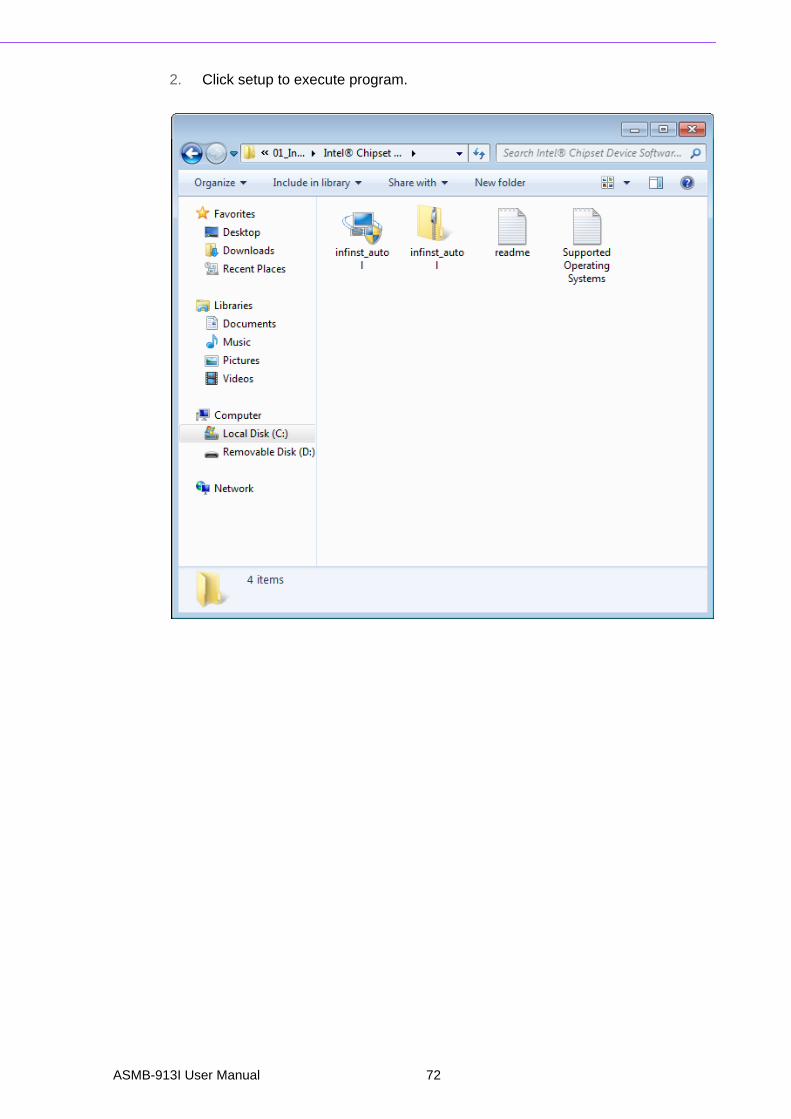
2. Click setup to execute program.
ASMB-913I User Manual 72

Chapter 5
5 VGA Setup
5.1 IntroductionInstall the ASPEED VGA driver to enable this function, which includes the followingfeatures:
32-bit 2D graphics engine on board for normal use. 64 MB RAM for this chip, the highest resolution is 1920x1200.
5.2 Windows Series Driver SetupInsert the driver CD into your system's CD-ROM drive. When the folder is displayed,navigate to the "02_Graphic chip" folder and click the executable file to complete theinstallation of the drivers for OS that you need.
ASMB-913I User Manual 74

Chapter 5
VG
A S
etup
Note! 1. If ASMB-913I carries an additional graphics card for VGA output, please set this additional graphic card as "major output" under the "Display properties" of OS.
2. Please use the driver file from "Windows WDDM" folder as first choice.
3. XDDM and WDDM Driver Selection for Win7/Vista/2008/2008R2 OS.– In general, we strongly recommend our customers to use XDDM
driver, not WDDM driver. ASPEED’s WDDM driver is only for the motherboard which supports multi-adapters function. Multi-adapter function means the mother board has 2 different VGA chips (or add-on cards) on-board, one is the 3rd party VGA chip, another is ASPEED VGA chip, and the 3rd party VGA chip only provides WDDM driver.
4. ASPEED Graphics WDDM Driver Limitation on Vista/Windows7/Server2008/Server2008R2– It is non-WHQL certified driver because ASPEED VGA is a 2D
VGA, it cannot meet the WHQL requirement of WDDM driver which requires 3D VGA function.
– Because it is non-WHQL certified driver, it may meet some com-patible issues with some specific applications
5. ASPEED Graphics WDDM Driver Limitation on Windows 8/2012:– Not support the modes with different display frequency
75 ASMB-913I User Manual

ASMB-913I User Manual 76
Chapter 6
6 LAN Configuration & USB 3.0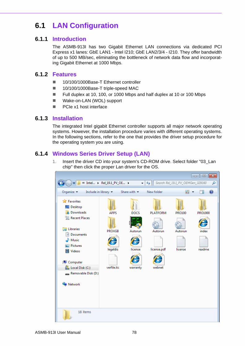
6.1 LAN Configuration
6.1.1 IntroductionThe ASMB-913I has two Gigabit Ethernet LAN connections via dedicated PCIExpress x1 lanes: GbE LAN1 - Intel I210; GbE LAN2/3/4 - I210. They offer bandwidthof up to 500 MB/sec, eliminating the bottleneck of network data flow and incorporat-ing Gigabit Ethernet at 1000 Mbps.
6.1.2 Features 10/100/1000Base-T Ethernet controller 10/100/1000Base-T triple-speed MAC Full duplex at 10, 100, or 1000 Mbps and half duplex at 10 or 100 Mbps Wake-on-LAN (WOL) support PCIe x1 host interface
6.1.3 InstallationThe integrated Intel gigabit Ethernet controller supports all major network operatingsystems. However, the installation procedure varies with different operating systems.In the following sections, refer to the one that provides the driver setup procedure forthe operating system you are using.
6.1.4 Windows Series Driver Setup (LAN)1. Insert the driver CD into your system's CD-ROM drive. Select folder "03_Lan
chip" then click the proper Lan driver for the OS.
ASMB-913I User Manual 78

Chapter 6
LAN
Configuration
&U
SB
3.0
6.2 USB 3.0
6.2.1 IntroductionASMB-913I offers two USB 3.0 ports in rear side. The USB 3.0 could provide thebandwidth up to 500MB/s to shorter the time for data transmission.
6.2.2 Windows Series Driver SetupInsert the driver CD into your system's CD-ROM drive. Select folder "04_USB3.0chip" then click the proper ".exe" driver file for the installation.
79 ASMB-913I User Manual
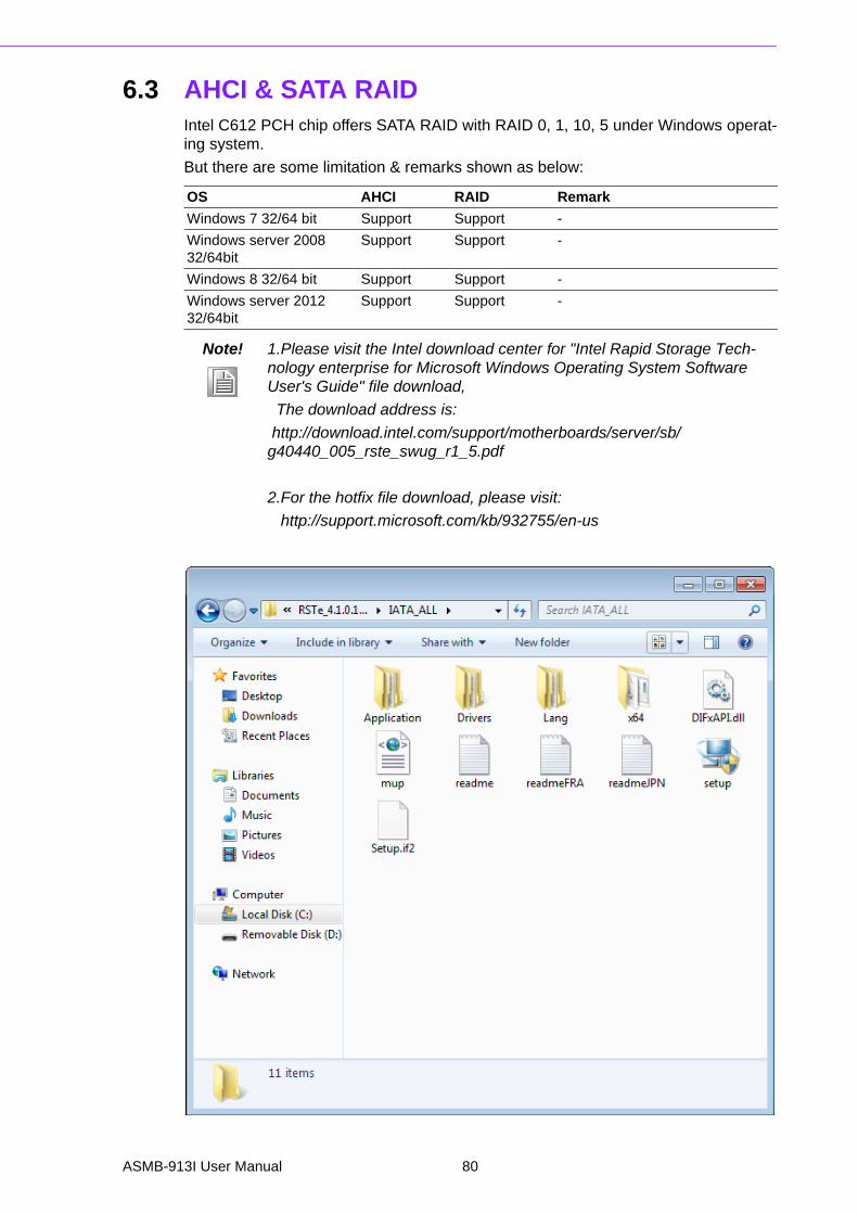
6.3 AHCI & SATA RAIDIntel C612 PCH chip offers SATA RAID with RAID 0, 1, 10, 5 under Windows operat-ing system.
But there are some limitation & remarks shown as below:
OS AHCI RAID Remark
Windows 7 32/64 bit Support Support -
Windows server 2008 32/64bit
Support Support -
Windows 8 32/64 bit Support Support -
Windows server 2012 32/64bit
Support Support -
Note! 1.Please visit the Intel download center for "Intel Rapid Storage Tech-nology enterprise for Microsoft Windows Operating System Software User's Guide" file download,
The download address is:
http://download.intel.com/support/motherboards/server/sb/g40440_005_rste_swug_r1_5.pdf
2.For the hotfix file download, please visit:
http://support.microsoft.com/kb/932755/en-us
ASMB-913I User Manual 80

Appendix A
A Programming the Watchdog Timer
The ASMB-913I’s watchdog timer can be used to monitor system software operationand take corrective action if the software fails to function within the programmedperiod. This section describes the operation of the watchdog timer and how to pro-gram it.
A.1 Watchdog Timer OverviewThe watchdog timer is built in to the super I/O controller NCT6776D. It provides thefollowing functions for user programming:
Can be enabled and disabled by user program Timer can be set from 1 to 255 seconds or 1 to 255 minutes Generates an interrupt or resets signal if the software fails to reset the timer
before time-out
A.2 Programming the Watchdog TimerThe I/O port address of the watchdog timer is 2E (hex) and 2F (hex). 2E (hex) is theaddress port. 2F (hex) is the data port. You must first write an address value intoaddress port 2E (hex), and then write/read data to/from the assigned register throughdata port 2F (hex).
ASMB-913I User Manual 82

Appendix A
Program
ming
theW
atchdogT
imer
Unlock NCT6776D
Select watchdog timer register
Enable the watchdogtimer function
Use the watchdog
Lock NCT6776D
timer function
83 ASMB-913I User Manual

A.2.1 Example ProgramsEnable watchdog timer and set 10 seconds as the timeout interval
;-----------------------------------------------------------
Mov dx,2eh ; Unlock NCT6776D
Mov al,87h
Out dx,al
Out dx,al
;-----------------------------------------------------------
Mov al,07h ; Select registers of watchdog timer
Out dx,al
Inc dx
in al,dx
Or al,08h
Out dx,al
;-----------------------------------------------------------
Dec dx; Enable the function of watchdog timer
Mov al,30h
Out dx,al
Inc dx
Mov al,01h
Out dx,al
;-----------------------------------------------------------
Table A.1: Watchdog Timer RegistersAddress of register (2E)
Read/ Write
Value (2F) & description
87 (hex) -Write this address to I/O address port 2E (hex) twice to unlock the NCT6776D
07 (hex) write Write 08 (hex) to select register of watchdog timer.
30 (hex) writeWrite 01 (hex) to enable the function of the watchdog timer. Dis-abled is set as default.
F5 (hex) write
Set seconds or minutes as units for the timer. Write 0 to bit 3: set seconds as counting unit. [default]. Write 1 to bit 3: set minutes as counting unit.Write 1 to bit 4: Watchdog timer count mode is 1000 times faster.If bit 3 is 0, the count mode is 1/1000 seconds mode. If bit 3 is 1, the count mode is 1/1000 minutes mode.
F6 (hex) write
0: stop timer [default]01 ~ FF (hex): The amount of the count, in seconds or minutes, depends on the value set in register F5 (hex). This number decides how long the watchdog timer waits for strobe before generating an interrupt or reset signal. Writing a new value to this register can reset the timer to count with the new value.
F7 (hex)read/write
Bit 6: Write 1 to enable keyboard to reset the timer, 0 to dis-able.[default]Bit 5: Write 1 to generate a timeout signal immediately and auto-matically return to 0. [default=0]Bit 4: Read status of watchdog timer, 1 means timer is “timeout”.
AA (hex) - Write this address to I/O port 2E (hex) to lock NCT6776F.
ASMB-913I User Manual 84

Appendix A
Program
ming
theW
atchdogT
imer
Dec dx ; Set second as counting unit
Mov al,0f5h
Out dx,al
Inc dx
In al,dx
And al,not 08h
Out dx,al
;-----------------------------------------------------------
Dec dx ; Set timeout interval as 10 seconds and start counting
Mov al,0f6h
Out dx,al
Inc dx
Mov al,10; 10 minutes
Out dx,al
;-----------------------------------------------------------
Dec dx ; lock NCT6776D
Mov al,0aah
Out dx,al
Enable watchdog timer and set 5 minutes as the timeout interval
;-----------------------------------------------------------
Mov dx,2eh ; unlock NCT6776D
Mov al,87h
Out dx,al
Out dx,al
;-----------------------------------------------------------
Mov al,07h ; Select registers of watchdog timer
Out dx,al
Inc dx
In al,dx
Or al,08h
Out dx,al
;-----------------------------------------------------------
Dec dx ; Enable the function of watchdog timer
Mov al,30h
Out dx,al
Inc dx
Mov al,01h
Out dx,al
;-----------------------------------------------------------
Dec dx ; Set minute as counting unit
Mov al,0f5h
Out dx, al
Inc dx
In al,dx
Or al, 08h
85 ASMB-913I User Manual

Out dx,al
;-----------------------------------------------------------
Dec dx ; Set timeout interval as 5 minutes and start counting
Mov al,0f6h
Out dx,al
Inc dx
Mov al,5; 5 minutes
Out dx,al
;-----------------------------------------------------------
Dec dx ; lock NCT6776D
Mov al,0aah
Out dx,al
Enable watchdog timer to be reset by mouse
;-----------------------------------------------------------
Mov dx,2eh ; unlock NCT6776D
Mov al,87h
Out dx,al
Out dx,al
;-----------------------------------------------------------
Mov al,07h ; Select registers of watchdog timer
Out dx,al
Inc dx
Mov al,08h
Out dx,al
;-----------------------------------------------------------
Dec dx ; Enable the function of watchdog timer
Mov al,30h
Out dx,al
Inc dx
In al,dx
Or al,01h
Out dx,al
;-----------------------------------------------------------
Dec dx ; Enable watchdog timer to be reset by mouse
Mov al,0f7h
Out dx,al
Inc dx
In al,dx
Or al,80h
Out dx,al
;-----------------------------------------------------------
Dec dx ; lock NCT6776D
Mov al,0aah
Out dx,al
Enable watchdog timer to be reset by keyboard
ASMB-913I User Manual 86
Appendix A
Program
ming
theW
atchdogT
imer
;-----------------------------------------------------------
Mov dx,2eh ; unlock NCT6776D
Mov al,87h
Out dx,al
Out dx,al
;-----------------------------------------------------------
Mov al,07h ; Select registers of watchdog timer
Out dx,al
Inc dx
Mov al,08h
Out dx,al
;-----------------------------------------------------------
Dec dx ; Enable the function of watchdog timer
Mov al,30h
Out dx,al
Inc dx
Mov al,01h
Out dx,al
;-----------------------------------------------------------
Dec dx ; Enable watchdog timer to be strobed reset by keyboard
Mov al,0f7h
Out dx,al
Inc dx
In al,dx
Or al,40h
Out dx,al
;-----------------------------------------------------------
Dec dx ; lock NCT6776D
Mov al,0aah
Out dx,al
Generate a time-out signal without timer counting
;-----------------------------------------------------------
Mov dx,2eh ; unlock NCT6776D
Mov al,87h
Out dx,al
Out dx,al
;-----------------------------------------------------------
Mov al,07h ; Select registers of watchdog timer
Out dx,al
Inc dx
Mov al,08h
Out dx,al
;-----------------------------------------------------------
Dec dx ; Enable the function of watchdog timer
Mov al,30h
87 ASMB-913I User Manual

Out dx,al
Inc dx
In al,dx
Or al,01h
Out dx,al
;-----------------------------------------------------------
Dec dx ; Generate a time-out signal
Mov al,0f7h
Out dx,al ;Write 1 to bit 5 of F7 register
Inc dx
In al,dx
Or al,20h
Out dx,al
;-----------------------------------------------------------
Dec dx ; lock NCT6776D
Mov al,0aah
Out dx,al
ASMB-913I User Manual 88

Appendix B
B I/O Pin Assignments
B.1 USB Header (USB89)
B.2 USB3.0 Header(USB2_3 & USB4_5)
Table B.1: USB Header (USB89)
Pin Signal Pin Signal
1 USB_VCC5 2 USB_VCC5
3 USB_D- 4 USB_D-
5 USB_D+ 6 USB_D+
7 GND 8 GND
9 Key 10 N/C
USB89
Table B.2: USB Header (USB23,USB45,USB67,USB89)
Pin Signal Pin Signal
1 +5 V 2 STDA_SSRX-
3 STDA_SSRX+ 4 GND
5 STDA_SSRX- 6 STDA_SSRX+
7 GND 8 D-
9 D+ 10 OC#
11 D+ 12 D-
13 GND 14 STDA_SSRX+
15 STDA_SSRX- 16 GND
17 STDA_SSRX+ 18 STDA_SSRX-
19 +5 V 20
2 110
11 19
ASMB-913I User Manual 90

Appendix B
I/O P
inA
ssignments
B.3 VGA Connector (VGA1)
B.4 RS-232 Interface (COM2)
Table B.3: VGA Connector (VGA1)
Pin Signal Pin Signal
1 RED 9 VCC
2 GREEN 10 GND
3 BLUE 11 N/C
4 N/C 12 SDT
5 GND 13 H-SYNC
6 GND 14 V-SYNC
7 GND 15 SCK
8 GND
5
15
1
11
10 6
Table B.4: RS-232 Interface (COM2)
Pin Signal
1 DCD
2 RXD
3 TXD
4 DTR
5 GND
6 DSR
7 RTS
8 CTS
9 RI
1 2
6 9
91 ASMB-913I User Manual

B.5 External Keyboard Connector (KBMS2)
B.6 System Fan Power Connector (SYSFAN0~2)
B.7 Power LED (JFP3)
Table B.5: External Keyboard Connector (KBMS2)
Pin Signal
1 KB CLK
2 KB DATA
3 MS DATA
4 GND
5 VCC
6 MS CLK
Table B.6: Fan Power Connector (SYSFAN0/SYSFAN1/SYSFAN2)
Pin Signal
1 GND
2 +12 V
3 DETECT
4 PWM
Table B.7: Power LED (JFP1)
Pin Function
1 LED power (3.3 V)
2 NC
3 Ground
1 2 3
ASMB-913I User Manual 92

Appendix B
I/O P
inA
ssignments
B.8 External Speaker Connector (JFP2)
B.9 Reset Connector (JFP1)
B.10 HDD LED Connector (JFP1)
Table B.8: External Speaker Connector (JFP2)
Pin Function
1 SPK+
4 NC
7 BZ-
10 SPK-
1 4 7 10
Table B.9: Reset Connector (JFP1)
Pin Signal
9 RESET
12 GND
9 12
Table B.10: HDD LED Connector (JFP1)
Pin Signal
2 HDD_LED+
5 HDD_LED-
2 5
93 ASMB-913I User Manual
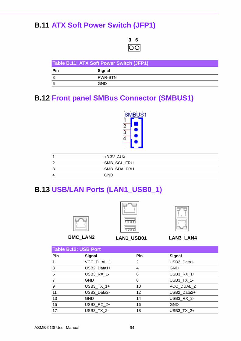
B.11 ATX Soft Power Switch (JFP1)
B.12 Front panel SMBus Connector (SMBUS1)
B.13 USB/LAN Ports (LAN1_USB0_1)
Table B.11: ATX Soft Power Switch (JFP1)
Pin Signal
3 PWR-BTN
6 GND
3 6
1 +3.3V_AUX
2 SMB_SCL_FRU
3 SMB_SDA_FRU
4 GND
Table B.12: USB PortPin Signal Pin Signal
1 VCC_DUAL_1 2 USB2_Data1-
3 USB2_Data1+ 4 GND
5 USB3_RX_1- 6 USB3_RX_1+
7 GND 8 USB3_TX_1-
9 USB3_TX_1+ 10 VCC_DUAL_2
11 USB2_Data2- 12 USB2_Data2+
13 GND 14 USB3_RX_2-
15 USB3_RX_2+ 16 GND
17 USB3_TX_2- 18 USB3_TX_2+
LAN1_USB01 LAN2_USB23
BMC_LAN2 LAN3_LAN4
ASMB-913I User Manual 94
Appendix B
I/O P
inA
ssignments
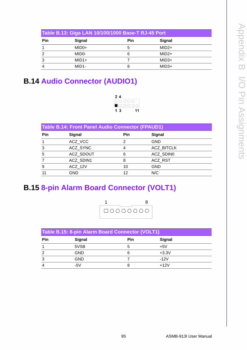
B.14 Audio Connector (AUDIO1)
B.15 8-pin Alarm Board Connector (VOLT1)
Table B.13: Giga LAN 10/100/1000 Base-T RJ-45 Port
Pin Signal Pin Signal
1 MID0+ 5 MID2+
2 MID0- 6 MID2+
3 MID1+ 7 MID3+
4 MID1- 8 MID3+
Table B.14: Front Panel Audio Connector (FPAUD1)
Pin Signal Pin Signal
1 ACZ_VCC 2 GND
3 ACZ_SYNC 4 ACZ_BITCLK
5 ACZ_SDOUT 6 ACZ_SDIN0
7 ACZ_SDIN1 8 ACZ_RST
9 ACZ_12V 10 GND
11 GND 12 N/C
Table B.15: 8-pin Alarm Board Connector (VOLT1)
Pin Signal Pin Signal
1 5VSB 5 +5V
2 GND 6 +3.3V
3 GND 7 -12V
4 -5V 8 +12V
1 8
95 ASMB-913I User Manual

B.16 Case Open Connector (JCASE1)
B.17 Front Panel LAN LED Connector (LANLED1)
Table B.16: Case Open Connector (JFP1)
Pin Signal
1 CASEOP
2 GND
1
2
Table B.17: LAN LED Connector (LANLED1)
Pin Signal Pin Signal
1 LAN1_LED0_ACT 2 LAN2_LED1_ACT
3 VCC3_LAN1LED 4 VCC3_LAN2LED
5 LAN1_LED1_1000M 6 LAN2_LED2_1000
7 LAN1_LED2_100M 8 LAN2_LED0_100
9 VCC3 10 N/C
ASMB-913I User Manual 96

Appendix B
I/O P
inA
ssignments
97 ASMB-913I User Manual

www.advantech.comPlease verify specifications before quoting. This guide is intended for referencepurposes only.All product specifications are subject to change without notice.No part of this publication may be reproduced in any form or by any means,electronic, photocopying, recording or otherwise, without prior written permis-sion of the publisher.All brand and product names are trademarks or registered trademarks of theirrespective companies.© Advantech Co., Ltd. 2015