Embed Size (px)
Citation preview

FiberControl Lightwave Polarization Solutions
1-888-91-FIBER toll free 732 332-1860 telephone 732 332-1861 facsimile
[email protected] email www.fibercontrol.com web
USER MANUAL and
PROGRAMMING GUIDE
FiberControl
Motorized Polarization Controller MPC1-01, Single Channel MPC1-02, Dual Channel MPC1-M, Quad Channel

ii
FiberControl Lightwave Polarization Solutions
1-888-91-FIBER toll free 732 332-1860 telephone 732 332-1861 facsimile
[email protected] email www.fibercontrol.com web
Please Note:
With the understanding and the desire of improving the clarity and readability
as well as to reduce omissions and correct errors, the information within this
manual is subject to change without notice.
FiberControl shall not be liable for any errors herein or for any accompanying
or subsequent damage in connection with the furnishing, operation, or use of
this material. With regard to this material, FiberControl makes no warrantee
regarding the suitability and fitness for any specific function, purpose, or use.
Base FiberControl part number: MPC1 Printed: 12-February, 2003
© Copyright FiberControl 2003
All rights reserved

iii
FiberControl Lightwave Polarization Solutions
1-888-91-FIBER toll free 732 332-1860 telephone 732 332-1861 facsimile
[email protected] email www.fibercontrol.com web
FiberControl’s goal is to produce the best-valued Lightwave Polarization
Solutions© to meet a wide range of applications in the field of optical
measurements. We greatly value input from our customers with ideas to improve
and enhance our existing products as well as expand our product-line. Please
feel free to offer your ideas and/or criticisms. We look forward to hearing from
you and in meeting your needs in the field of polarization.
– The Staff of FiberControl

iv
FiberControl Lightwave Polarization Solutions
1-888-91-FIBER toll free 732 332-1860 telephone 732 332-1861 facsimile
[email protected] email www.fibercontrol.com web
Warranty and Restrictions:
FiberControl (FC) warrants material and production of the MPC1 series for a
period of 12 months from the shipping date. During this warranty period, FC will
see to defaults arising from manufacturing via direct repair or replacement at
FC’s discretion. For warranty repairs or service, the unit must be sent back to FC
(U.S.A.) or to a place determined by FC. The customer will be responsible for
shipping costs to FC, and in case of warranty repairs, FC will cover the shipping
costs back to the customer. If no warranty repair is applicable, the customer will
be responsible to return shipping expenses. In case of shipment from outside the
United States, all duties (taxes, etc.) arising from the transfer will be the
responsibility of the customer.
FC warrants the hard-, firm-, and software designed by FC for this unit to operate
fault-free if they are handled according to our requirements. However, FC does
not warrant a fault-free and uninterrupted operation of the unit, of the soft-, firm-
or hardware, for any specific or special application(s) nor this instruction manual
to be error free. FC is not liable for consequential damages.
The warranty mentioned before does not cover errors and defects being the
result of improper treatment, software, or interface not supplied by us,
modifications, misuse or operation outside the defined ambient stated by us or
unauthorized maintenance. All further claims will not be consented to and will not
be acknowledged. FC does not explicitly warrant the usability or the economical
use for any application.
FC reserves the right to change this instruction manual or the technical data of
the described unit at any time. Removal of any of the top and/or bottom
enclosure cover’s screws even in only an effort to gain entry inside the enclosure
nullifies the MPC1 series’ warrantee and incurs the risk of physical harm.
v
FiberControl Lightwave Polarization Solutions
1-888-91-FIBER toll free 732 332-1860 telephone 732 332-1861 facsimile
[email protected] email www.fibercontrol.com web
Contact Information:
United States of America
FiberControl
P.O. Box 198
Holmdel, New Jersey 07733
phone: +1-732-332-1860
toll-free: +1-888-91-FIBER
fax: +1-732-332-1861
email: [email protected]
Web: http://www.fibercontrol.com
Call to obtain the ship to address.
Outside the U.S.A.
Several distributors throughout the world also represent FiberControl. Please refer to our web site or call our US based offices to ask for the nearest distributor.
vi
FiberControl Lightwave Polarization Solutions
1-888-91-FIBER toll free 732 332-1860 telephone 732 332-1861 facsimile
[email protected] email www.fibercontrol.com web
Assistance and Maintenance:
Calibration, service, and maintenance agreements for the MPC1 series of products are available from FiberControl. Assistance for proper product usage is also available.
Feel free to contact FiberControl via phone, fax, and/or email for assistance.

vii
FiberControl Lightwave Polarization Solutions
1-888-91-FIBER toll free 732 332-1860 telephone 732 332-1861 facsimile
[email protected] email www.fibercontrol.com web
Hazard and Warning Labels/Symbols: The following symbols have been placed at various points on the MPC1 product series. To ensure personal safety of users and those around them, the user must be familiar with their meaning before operating the unit. Assistance is available from FiberControl – see §Assistance and Maintenance, and §Warranty and Restrictions.
These symbols signify posted warnings where extreme caution is required, therefore, it is not recommended to proceed past them into the enclosure. These symbols do not imply that FiberControl recommends the user to proceed inside the enclosure but instead that if the user does choose to proceed it must be with great caution. Moreover, entry into the enclosure not only incurs the risk of physical harm, but also nullifies the MPC1 product series’ warrantee.
Silk-screened onto the back of the MPC1 products is the following “Caution High Voltage” symbol. This symbol, shown as a lightning bolt inside an equilateral triangle, warns of the presence of “life-threatening” voltages inside of the enclosure if entered by the user.
"Caution High Voltage" symbol On the inside of the MPC1 products, the locations of these “life-threatening” voltages are not specifically marked. Therefore, significant and meaningful personal physical risk is present for anyone not completely familiar with the MPC1 series’ design. The level of risk also holds true for the measurement and test equipment of the user.

viii
FiberControl Lightwave Polarization Solutions
1-888-91-FIBER toll free 732 332-1860 telephone 732 332-1861 facsimile
[email protected] email www.fibercontrol.com web
The “Caution” symbol, shown below as the exclamation point inside a equilateral triangle, is also silk-screened on the back of the MPC1 product series denoting the requirement of extreme caution if the enclosure is entered into or if the exterior is cleaned with liquids.
"Caution" symbol
!
Again, assistance is available from FiberControl – please refer to §Assistance and Maintenance, and §Warranty and Restrictions. To insure the personal / physical safety of the operator, it is recommended that the top and / or bottom covers of the MPC1 product series never be removed at any time. The MPC1 series of products are only to be cleaned with a lightly damp cloth, regardless of the precautions and care undertaken by the user doing the cleaning.

ix
FiberControl Lightwave Polarization Solutions
1-888-91-FIBER toll free 732 332-1860 telephone 732 332-1861 facsimile
[email protected] email www.fibercontrol.com web
Ground Label/Symbol: Located on the inside of the MPC1 product series, near the switching power supply, is the symbol for the “Protective Earth,” shown below. This ground symbol is placed next to the green/yellow striped ground wire that attaches near the power supply on the side of the enclosure and the ground connection on the power entry module. Consistent with CE marking requirements, this procedure ensures that all metal portions of the enclosure are properly grounded.
"Protective Earth" symbol Despite the grounding design and procedure, the MPC1 series of products are only to be cleaned with a lightly damp cloth, regardless of the precautions and care undertaken by the user doing the cleaning,

x
FiberControl Lightwave Polarization Solutions
1-888-91-FIBER toll free 732 332-1860 telephone 732 332-1861 facsimile
[email protected] email www.fibercontrol.com web
High-Level View of this User Guide: The FiberControl MPC1 product series’ User Manual and Programming Guide is organized as follows: Section 1 Setup and Preparation Section 2 Specifications and General Information Section 3 General Concepts and Applications Section 4 Front and Rear-Panel Description Section 5 Remote Operation: The MPC1 Command Set Appendix A Instructional Program, Example AutoScan Code Appendix B LabView® Driver, Example GPIB and RS-232 Code Appendix C Instructional Program, Example Binary Transparent Mode Code Appendix D Front-Panel Quick Reference

xi
FiberControl Lightwave Polarization Solutions
1-888-91-FIBER toll free 732 332-1860 telephone 732 332-1861 facsimile
[email protected] email www.fibercontrol.com web
Table of Contents
1 Setup and Preparation ...................................................................1
1.1 Tabletop Unit.......................................................................................... 1 1.2 Rack Mounting the Tabletop Unit........................................................... 2
2 Specifications and General Information.........................................4 3 General Concepts and Applications ..............................................8
3.1 Introduction ............................................................................................ 8 3.2 Applications............................................................................................ 9
4 Front and Rear-Panel Description ...............................................11 4.1 General ................................................................................................ 11 4.2 Front-Panel Display and User Interface (Manual Operation) ............... 12
4.2.1 General Usage, Powering-up and Powering-down ....................... 12 4.2.2 Local ............................................................................................. 15 4.2.3 Toggling Between Multiple Channels (MPC1-02 and MPC1-04) .. 17 4.2.4 Changing Waveplate Angular Resolution ..................................... 18 4.2.5 Centering Waveplates................................................................... 19 4.2.6 Adjusting Rotational Speed (RATE).............................................. 20 4.2.7 Position Memory Preset................................................................ 23 4.2.8 Recalling....................................................................................... 24 4.2.9 AutoScan Mode ............................................................................ 25
4.2.9.1 AutoScan, Overview .............................................................. 25 4.2.9.2 AutoScan Mode, SOP Scramble............................................ 25 4.2.9.3 AutoScan Mode, User Defined .............................................. 26 4.2.9.4 Programming and AutoScan Program................................... 27 4.2.9.5 Example AutoScan program.................................................. 29 4.2.9.6 Recalling an AutoScan Program............................................ 29
4.2.10 Utilities .......................................................................................... 30 4.3 Rear-Panel........................................................................................... 30
5 Remote Operation: The MPC1 Command Set ............................32 5.1 General ................................................................................................ 32
5.1.1 GPIB Configuration....................................................................... 32 5.1.2 RS-232 Configuration ................................................................... 34
5.2 Command Structure of MPC1.............................................................. 35 5.2.1 Waveplate Motion Control of MPC1.............................................. 37 5.2.2 Inquiry of Axis Position.................................................................. 39 5.2.3 Re-Centering All Waveplates........................................................ 40 5.2.4 Angular Velocity Control of MPC1 Lefèvre Waveplates................ 41 5.2.5 Inquiry of Assigned Rate............................................................... 42 5.2.6 Remote Invocation of Auto Mode and Scramble Mode................. 42
5.3 IEEE-488.2 Command Status Support ................................................ 43
xii
FiberControl Lightwave Polarization Solutions
1-888-91-FIBER toll free 732 332-1860 telephone 732 332-1861 facsimile
[email protected] email www.fibercontrol.com web
5.3.1 Status Byte Register Control Mechanisms.................................... 44 5.3.2 Event Standard Register Control Mechanisms ............................. 46
5.4 MPC1 GPIB Remote Programming ..................................................... 47 5.5 MPC1 Serial (RS-232) Remote Programming ..................................... 57 5.6 MPC1 Binary Transparent Mode Remote Programming...................... 58
5.6.1 Issuing a Motion Command in Transparent Mode ........................ 60 5.6.2 Issuing a RATE Change command in Transparent Mode............. 62 5.6.3 Exiting Transparent Mode............................................................. 62
Appendix A: Instructional Program, Example AutoScan Code..........64 Appendix B: LabView® Driver, Example GPIB and RS-232 Code.....65 Appendix C: Instructional Program, Example Binary Transparent Mode Code.........................................................................................66 Appendix D: Front-Panel Quick Reference........................................67

xiii
FiberControl Lightwave Polarization Solutions
1-888-91-FIBER toll free 732 332-1860 telephone 732 332-1861 facsimile
[email protected] email www.fibercontrol.com web
Tables
Table 1: Optical specifications.............................................................................. 4 Table 2: Instrumentation control ........................................................................... 5 Table 3: Line power and temperature................................................................... 6 Table 4: Physical characteristics of the MPC1 ..................................................... 6 Table 5: Angular rotational movement per detent and the corresponding display
indication..................................................................................................... 18 Table 6: A convenient tabular form showing how the RATE setting corresponds
to the Stokes’ angular velocity (°/sec). ........................................................ 22 Table 7: Hardware settings for RS-232 communication. .................................... 34 Table 8: RS-232 pin assignments for MPC1. ..................................................... 34 Table 9: Standard IEEE 488.2 status byte bit assignments................................ 45 Table 10: Detailed IEEE-488.2 bit assignments. ................................................ 45

xiv
FiberControl Lightwave Polarization Solutions
1-888-91-FIBER toll free 732 332-1860 telephone 732 332-1861 facsimile
[email protected] email www.fibercontrol.com web
Figures
Figure 1: One of the two tapped front enclosure housing bezels, part #: MPC1-
18001. ........................................................................................................... 2 Figure 2: Rack-mount mounting frame, part #: MPC1-18002............................... 3 Figure 3: An example showing the rotation of a single fractional waveplate
displayed as a polarimetric plot on the Poincaré Sphere and on the Observable Polarization Sphere.................................................................... 9
Figure 4: The front panel displays of the MPC1 family of products. The single channel MPC1-01 (Top), the two channel MPC1-02 (Middle), and the four channel MPC1-M (Bottom).......................................................................... 11
Figure 5: MPC1-02 front panel showing Lefèvre loop waveplate and angular velocity controls........................................................................................... 14
Figure 6: Identification and control features that enable toggling between either of the channels of MPC1-02............................................................................ 17
Figure 7: RATE value vs. angular velocity of Lefèvre waveplates for the MPC1 series. ......................................................................................................... 20
Figure 8: Location of the RECALL, SAVE, and SHIFT keys............................... 23 Figure 9: Location of the relevant AutoScan keys .............................................. 26 Figure 10: Line voltage and fusing information located on the rear-panel of the
MPC1-01 and MPC1-02.............................................................................. 31 Figure 11: Line voltage and fusing information located on the rear-panel of the
MPC1-M. ..................................................................................................... 31 Figure 12: A screen shot of Paddle_Cycle_1_MULTI......................................... 48 Figure 13: Annotated string assembly for delivery to the GPIB port in Labview.
This string concatenation is from the single channel version of MPC1. ...... 49 Figure 14: Output String concatenation. Notice this command creates the GPIB
Command "Xc=-99" C=either “A” or “B” to designate the channel assignment.................................................................................................. 50
Figure 15: Implementation of "Conditional GPIB Delay." Use this Labview function to confirm MPC1 is ready to accept a new motion command before issuing a new command.............................................................................. 52
Figure 16: A screen shot of MPC1 Interactive control. ....................................... 54 Figure 17: LabView core code for receiving and transmitting to MPC1. Notice the
bus arbitration performed via the “wait for RQS” command (item C.).......... 55
1
FiberControl Lightwave Polarization Solutions
1-888-91-FIBER toll free 732 332-1860 telephone 732 332-1861 facsimile
[email protected] email www.fibercontrol.com web
1 Setup and Preparation
1.1 Tabletop Unit
The MPC1 series was designed primarily as a tabletop unit. Four small rubber pads have been placed at the corners on the underside providing anti-skid protection and to protect the table’s surface. While designed with the rubber pads positioned on a table, the MPC1 can be oriented in any desired direction, i.e., upside down or on any of its sides, with the only caveat being the equipment’s secure placement to ensure the safety of the end-user as well as others. Plug appropriate end of the provided power cord into the MPC1’s IEC-320 receptacle and the other end into a properly grounded electrical outlet. Press the power switch in the lower left-hand corner of the front panel to turn the unit on (see section 4.2.1 for more details on powering-up and powering-down the unit). With the unit secured in place, the optical fibers can be attached. Be sure to follow proper cleaning procedure for the connectors prior to inserting them into the bulkhead feedthrough (e.g., using compressed air to remove particles).

2
FiberControl Lightwave Polarization Solutions
1-888-91-FIBER toll free 732 332-1860 telephone 732 332-1861 facsimile
[email protected] email www.fibercontrol.com web
1.2 Rack Mounting the Tabletop Unit While the MPC1 family of polarization controllers has been designed primarily as desktop units, they can also be rack mounted. This section discusses the various mounting brackets available.
For the MPC1 single channel and double channel units (MPC1-01 and MPC1-02), the following hardware options apply:
• Part #: MPC1-18001, Tapped front enclosure housing bezels (one pair), factory installed,
• Part #: MPC1-18002, Rack-mount mounting frame (19” x 3 ½ “ x 1/8”),
• Part #: MPC1-180003, Rack-mount screws (#10-32 flat-head, two pair).
Below are two figures (Figure 1 and Figure 2) showing two of these parts.
.217
1.312
.656
CL
10-32 2b TAP THRUTYP. 2 PLACES
CL
Figure 1: One of the two tapped front enclosure housing bezels, part #: MPC1-18001.

3
FiberControl Lightwave Polarization Solutions
1-888-91-FIBER toll free 732 332-1860 telephone 732 332-1861 facsimile
[email protected] email www.fibercontrol.com web
The first is the tapped front housing bezel, Figure 1, in place of the existing untapped bezels. Since it requires the removal of the top and bottom covers, installing these is done at the factory. The standard desktop version of the MPC1’s front housing bezels does not have the pair of tapped mounting holes (#10-32) displayed in Figure 1.
The mounting frame, shown below in Figure 2, is 1/8” thick, 3½” wide, and 19” long. With the tapped front enclosure housing bezels replacing the stock bench-top bezels, the front panel of the MPC1 mounts through the center of the opening and secured with two pair (4) #10-32 flat-head Phillips stainless-steel machine screws.
0.00
0
0.25
00.
400
Figure 2: Rack-mount mounting frame, part #: MPC1-18002.
If desired, the four-channel MPC1-04 can be supplied with rack mounting capability (MPC1–04…PC–R option). With this option, the chassis of the unit contains mounting flanges that are immediately compatible to the standard 19’’ equipment rack rails.
4
FiberControl Lightwave Polarization Solutions
1-888-91-FIBER toll free 732 332-1860 telephone 732 332-1861 facsimile
[email protected] email www.fibercontrol.com web
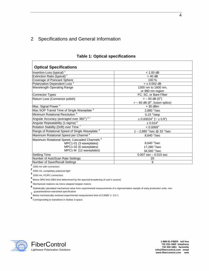
2 Specifications and General Information
Table 1: Optical specifications
Optical Specifications Insertion-Loss (typical) 1 < 1.00 dB Extinction Ratio (typical) 2 > 40 dB Coverage of Poincaré Sphere 100 % Polarization Dependent Loss 3 < ± 0.002 dB Wavelength Operating Range
1300 nm to 1600 nm, or 980 nm region
Connector Types FC, SC, or Bare Fiber Return Loss (Connector polish)
> – 50 dB (0°) > – 60 dB (8°, fusion splice)
Max. Signal Power 4 + 30 dBm Max SOP Transit Time of Single Waveplate 8 2,880 °/sec Minimum Rotational Resolution 5 0.15 °/step Angular Accuracy (averaged over 360°) 6, 7 ± 0.00024° (< ± 0.9”) Angular Repeatability (1-sigma) 6 ± 0.014° Rotation Stability (Drift) over Time 7 < 0.0069° Range of Rotational Speed of Single Waveplate 8 1 – 2,880 °/sec @ 33 °/sec Maximum Rotational Speed per Channel 8 8,640 °/sec Maximum Rotational Speed, Cascaded Channels 8 MPC1-01 (3 waveplates) MPC1-02 (6 waveplates) MPC1-M (12 waveplates)
8,640 °/sec 17,280 °/sec 34,560 °/sec
Settling Time 0.007 sec – 0.015 sec Number of AutoScan Rate Settings 20 Number of Save/Recall Settings 9
1 1550 nm with connectors
2 1550 nm, completely polarized light
3 1550 nm, FC/PC connectors
4 Below SRS limit (SBS limit determined by the spectral broadening of user’s source)
5 Mechanical rotations via micro-stepped stepper motors
6 Statistically calculated mechanical value from experimental measurements of a representative sample of early production units, non-
guaranteed/non-warranted specification 7 Below mechanically resolved experimental measurement limit of 0.0069° (< 0.5 ’)
8 Corresponding to transitions in Stokes 3-space

5
FiberControl Lightwave Polarization Solutions
1-888-91-FIBER toll free 732 332-1860 telephone 732 332-1861 facsimile
[email protected] email www.fibercontrol.com web
Table 2: Instrumentation control
INSTRUMENTATION CONTROL Parallel Control Interface MPC1-01 MPC1-02 MPC1-M
GPIB (IEEE 488.2) 1 port 1 port 1 port
Serial Control Interfaces MPC1-01 MPC1-02 MPC1-M
EIA-RS232 & Binary Transparent Mode 1 port 1 port 2 ports
Response Time† ≤ 5 msec Software Compatibility w/ GUI interface
Labview 6.0, or any other GPIB capable development environment
System Controller Embedded Microcontroller, 40 MHz GPIB Controller / Processor National Instruments µPD7210
Operating Systems Windows 95, Windows 98, Win NT 4.0, Win2000 Pro, Windows XP
Front Panel Control Interface‡ Display(s) MPC1-01 MPC1-02 MPC1-M Waveplate Rotation SOP Scramble SOP AutoScan© (pseudo-random) Rotational Step Rate Rotational Step Size Centering Waveplates Channel Select GPIB Local
1 1, toggled between channels 2, toggled between channel pairs Three independent encoders (cw/ccw) One button actuation (start/stop) User algorithms entered at front panel
or via GUI Adjusted with one button and
corresponding encoder Adjusted by depressing encoder(s) One button actuation Two button actuation Adjusted with one button and encoder One button actuation
† - w/ GPIB (IEEE-488.2), EIA-RS-232, and Binary Transparent Mode
‡ - MPC1-01; MPC1-02, per optical channel; MPC1-M, per optical channel for each of two independent interfaces

6
FiberControl Lightwave Polarization Solutions
1-888-91-FIBER toll free 732 332-1860 telephone 732 332-1861 facsimile
[email protected] email www.fibercontrol.com web
Table 3: Line power and temperature
LINE POWER / TEMPERATURE Electrical Input Voltage 85 VAC – 264 VAC, auto-switching Line Frequency 47 – 63 Hz Power Dissipation (nominal) MPC1-01 MPC1-02 MPC1-M
11.0 W 19.9 W 41.5 W
Fusing Requirements MPC1-01 MPC1-02 MPC1-M
1 Amp 1 Amp 1 Amp
Power Receptacle IEC 320 Power Supply Efficiency (nominal) 82 % Operating Temperature – 10 °C to + 35 °C
Table 4: Physical characteristics of the MPC1
PHYSICAL Overall H x W x D
(Metric) Overall H x W x D
(English) Enclosure
Height Enclosure
Width Dimensions MPC1-01 MPC1-02 MPC1-M (desktop) MPC1-M (rack-mount) MPC1-18002 (r-m kit)
9.2 x 23.5 x 40 cm 9.2 x 23.5 x 40 cm 9.2 x 44.8 x 40 cm 8.9 x 48.3 x 40 cm 8.9 x 48.3 x 0.3 cm
3 5/8 x 9¼ x 15¾ " 3 5/8 x 9¼ x 15¾ " 3 5/8 x 17.5 x 15¾ " 3½ x 19 x 15¾ " 3½ x 19 x 1/8 "
2U 2U 2U 2U 2U
46.25HP 46.25HP 88.12HP 88.12HP 88.12HP
Weight MPC1-01 MPC1-02 MPC1-M (desktop) MPC1-M (rack-mount) MPC1-18002 (r-m kit)
35.7 N (3.64 kg) 41.4 N (4.23 kg) 70.8 N (7.22 kg) 70.6 N (7.20 kg) 2.1 N (0.22 kg)
8.03 lbs. 9.32 lbs.
15.92 lbs. 15.88 lbs. 0.48 lbs.
Note:
• Overall heights (H) of desktop units include the presence of skid-resistant rubber pads, 0.32 cm (1/8 ”) thick.
• Overall widths (W) of rack-mount units include mounting hardware • 1U = 4.44 cm (1 3/4 “) • 1HP = 0.51 cm (0.2 “) • MPC1-18002 rack-mount faceplate enables the MPC1-01 and MPC1-02 to be rack mounted.

7
FiberControl Lightwave Polarization Solutions
1-888-91-FIBER toll free 732 332-1860 telephone 732 332-1861 facsimile
[email protected] email www.fibercontrol.com web
Declaration of Conformity Declaration de Conformité
Konformitätserklärung
FiberControl P.O. Box 198
Holmdel, New Jersey 07733 U.S.A.
declares under its own responsibility, that the product:
Motorized Polarization Controller, MPC1
conforms to the following product Directives and Standards:
Safety: 73/23/EEC, 1973 Low Voltage Directive 93/68/EEC, 1993 including amendments to Directive EN 60950: 1992 Standard, including amendments 1, 2, 3, 4, and 11
EMC:
89/336/EEC EMC Directive EN 50081-1, 1992 Standard, Electromagnetic Compatibility – emissions EN 55022, 1998 Standard – emissions EN 61000-3-2, 1995 Standard – emissions EN 61000-3-3, 1995 Standard – emissions
EN 50082-1, 1997 Standard, Electromagnetic Compatibility – immunity EN 61000-4-2, 1995 Standard – immunity EN 61000-4-3, 1995 Standard – immunity EN 61000-4-4, 1995 Standard – immunity EN 61000-4-5, 1995 Standard – immunity EN 61000-4-6, 1995 Standard – immunity EN 61000-4-11, 1995 Standard – immunity
Supplementary Information: Since this product conforms to the requirements of the Low Voltage Directive 73/23/EEC and the EMC Directive 89/336/EEC, the MPC1 carries the CE marking.
Holmdel, New Jersey, USA June 28, 2002
J. D. Evankow, Jr. / MTS

8
FiberControl Lightwave Polarization Solutions
1-888-91-FIBER toll free 732 332-1860 telephone 732 332-1861 facsimile
[email protected] email www.fibercontrol.com web
3 General Concepts and Applications
3.1 Introduction This manual describes the operation and specifications of FiberControl’s Polarization Controller, MPC1. The MPC1 alters the state-of-polarization (SOP) of light within single-mode optical fibers. It provides a user-friendly front panel interface for direct interaction, as well as real-time computer control via GPIB 488.2 and RS-232. Stable long-term preservation of output SOPs is inherent in this technique. The MPC1 is capable of altering the SOP over a wide range of wavelengths while minimally impacting the other optical parameters:
• Ultra-low insertion loss, • Ultra-low reflection, and • Ultra-low PDL.
Based on a technique originally developed by Hervé C. Lefèvre at Stanford University, the MPC1 utilizes stress-induced birefringence to alter and control the SOP of the polarized components of light. With one continuous length of optical fiber formed into individual coils, commonly referred to as Lefèvre loops, multiple independent sets of fiber loops are secured to separate paddles. Each paddle with its corresponding set of fiber loops act as fractional waveplates. These waveplates can be rotated independently. Adjustments in the angular orientation of these paddles alter the SOP of the incident light and provide complete coverage of the Poincaré sphere.

9
FiberControl Lightwave Polarization Solutions
1-888-91-FIBER toll free 732 332-1860 telephone 732 332-1861 facsimile
[email protected] email www.fibercontrol.com web
3.2 Applications The control and manipulation of the SOP is fundamental within the field of optics. While polarized light constrained within optical fiber is easy to move from one part of the laboratory to another, any movement of the fiber causes the SOP to be altered. For those involved in fiber-optic research, development, and manufacturing controlling these variations in SOP is critical.
Figure 3: An example showing the rotation of a single fractional waveplate displayed as a
polarimetric plot on the Poincaré Sphere and on the Observable Polarization Sphere.
In Figure 3, the displayed image shows two representations of the Stokes parameters plotted in 3-space (i.e., Poincaré Sphere and the Observable Polarization Sphere). With
10
FiberControl Lightwave Polarization Solutions
1-888-91-FIBER toll free 732 332-1860 telephone 732 332-1861 facsimile
[email protected] email www.fibercontrol.com web
both spheres, the portion of the curve in red corresponds to front surface of the sphere; blue the back surface. Changes in the physical orientation of the MPC1s’ paddles, move the output SOP. Figure 3 shows an example of the movement in Stokes Space resulting from the rotational movement of one paddle. In this particular example, the SOP at the input of the rotated paddle, waveplate, is close to linear resulting in a nearly balanced set of lobes crossing in the center, i.e., close to the characteristic “figure eight” curve. Any arbitrary output SOP (i.e., any portion of Stokes Space) can be achieved by moving all three paddles. Many applications exist for the MPC1, a few examples are:
• PDL system and component measurements, • Polarization stabilization, with appropriate feedback, • Low / medium speed polarization scrambler, • As a component in a PMD emulator or compensator, • EDFA noise-figure measurements to remove the input signal, • Semiconductor optical amplifiers measurements, • Interferometric experiments, • Coherence sources and receivers, and • General use throughout the laboratory.

11
FiberControl Lightwave Polarization Solutions
1-888-91-FIBER toll free 732 332-1860 telephone 732 332-1861 facsimile
[email protected] email www.fibercontrol.com web
4 Front and Rear-Panel Description
4.1 General The MPC1 Polarization Controller provides high-performance polarization control, together with a flexible and easy-to-use user interfaces. The front and rear-panel interfaces enable the user to perform all operations. By coupling an alphanumeric LCD display with an intuitive front-panel control system, the MPC1’s core functionality may be used with minimal instruction. The MPC1 also features nonvolatile memory, via EEPROM, storing critical system information and user settings for later recall – even after power is removed from the instrument.
Figure 4: The front panel displays of the MPC1 family of products. The single channel MPC1-01 (Top), the two channel MPC1-02 (Middle), and the four channel MPC1-M (Bottom).

12
FiberControl Lightwave Polarization Solutions
1-888-91-FIBER toll free 732 332-1860 telephone 732 332-1861 facsimile
[email protected] email www.fibercontrol.com web
The rear-panel provides the easy access for connecting line-power (via IEC-320) and control cabling (i.e., EIA-RS232, and GPIB IEEE 488.2). It also contains the warning labels and fusing information. In the sections to follow, when a three-dimensional box surrounds a word, it represents a key or button on the front-panel:
“BUTTON”
Please note: Sections of text surrounded by boxes with 10% gray-level (similar to this example), periodically listed throughout the manual, are intended as concise summaries to aid the user. These summaries are grouped together in Appendix D.
4.2 Front-Panel Display and User Interface (Manual Operation)
4.2.1 General Usage, Powering-up and Powering-down To power-up the MPC1, press the large dark-colored button in the lower left front-panel marked POWER. An integrated green LED will light indicating the unit is powered. A pictorial diagram is also shown designating the operation of the powering (i.e., depressed button corresponding to “powered on” (“1”) and the out button position corresponding to “unpowered” (“0”)). If the LED does not light, verify that the power cord is connected and/or that the line voltage is within the proper range (see MPC1 input power specifications in section 2).

13
FiberControl Lightwave Polarization Solutions
1-888-91-FIBER toll free 732 332-1860 telephone 732 332-1861 facsimile
[email protected] email www.fibercontrol.com web
To Power-up the MPC1:
Attach provided power cord by mating C13 plug to the MPC1’s IEC-320
receptacle, then insert plug end into line power, and push the POWER
key once.
• Integrated green LED will light. • All waveplates simultaneously align to the last known position. • Very light tapping sound may be heard during waveplate
initialization. The MPC1, on power-up, runs through a self-test initialization process automatically moving all waveplates to a preliminary position. This operation completes within seconds (depending on the rate setting) and is accompanied by a rapid, slightly audible, tapping sound. Immediately following, the user system is available for use. After initialization, MPC1 will recall and position all waveplates to their last assigned positions. Hence, the instrument will recall its own settings from the last time the system was used. Even if the MPC1 is unplugged for a prolonged duration, the last known position will be recalled as this position information is held in non-volatile memory. Individually and independently rotatable, front-panel encoders control the angles of each of three Lefèvre waveplates. These are shown in Figure 5 above the row of push buttons. For ease of reference within this Manual, each of the three encoders refers to the internal waveplates as left (or left-hand), center, and right (or right-hand), left-to-right, respectively.

14
FiberControl Lightwave Polarization Solutions
1-888-91-FIBER toll free 732 332-1860 telephone 732 332-1861 facsimile
[email protected] email www.fibercontrol.com web
Figure 5: MPC1-02 front panel showing Lefèvre loop waveplate and angular velocity controls.
Clockwise motion of the encoder provides positive rotation of the corresponding Lefèvre waveplate. Likewise, counter-clockwise rotation of the encoder provides negative rotation of the waveplate. The range of motion of each Lefèvre waveplate is limited to –99° -> +99° in increments ranging from 0.15° to 15°. With each motion of an encoder, the LCD display will report the given position of the waveplate. Each waveplate’s encoder provides resolution control. This resolution is determined by the incremental excursion provided by a given encoder’s rotational detent, i.e., the faintly perceptible physical sensation of a “snap or tick” as the encoder’s knob is rotated. Angular resolution (in degrees/detent) is changed by gently pressing any given encoder’s knob inward (towards the instrument). By pressing any given encoder, pushing in the adjustment knob, the resolution of that waveplate is individually and independently changed. The top row of the LCD display reports the selected degrees/tick setting. Resolution settings are toggled between very-fine (0.15° per tick), fine (1.5° per tick), medium (6.0° per tick), and coarse (15° per tick). Pressing the encoder while the waveplate resolution is on a coarse setting cycles the resolution back to the very-fine setting. For additional information on altering the waveplates‘ angular resolution, see section 4.2.4. When any waveplate is moved manually at the front panel, the MPC1 commits the position to memory within 3ms, thereby, automatically enabling the angular position of all waveplates to be reset on the next power-up. This short interval

15
FiberControl Lightwave Polarization Solutions
1-888-91-FIBER toll free 732 332-1860 telephone 732 332-1861 facsimile
[email protected] email www.fibercontrol.com web
provides adequate time for the user’s angular settings to be saved in all but the most severe power failure conditions. It is important to note that this memory functionality does not exist, however, when motion commands are invoked via remote control, user entered pre-set programs, or the scramble mode. The resolution is also not saved in memory – on power-up it will be set to the default 0.15° per tick. Powering down an energized MPC1 is a simple matter of pushing the power key once. All LEDs on the MPC1, specifically those at the upper right hand side of the front panel (i.e., MPC1-02, and MPC1-M) and the one integrated into the power switch will dim slowly over the course of a few seconds. The backlights on the display (MPC1-01) or displays (MPC1-02 and MPC1-M) will dim as the alphanumeric information fades to a dark blue. If so desired, the power cord can now be removed from the back panel’s IEC-320 receptacle. To Power-down the MPC1:
Push the POWER key once.
• The once lighted integrated green LED will dim slowly over a few
seconds until dark. • The display(s) backlight dims and the alphanumeric information
fades until the overall display(s) becomes dark blue.
4.2.2 Local The LOCAL key, located at the left most position in the row of keys, removes the MPC1 from remote GPIB control. Prior to pressing the LOCAL key, the word “*Remote*” is listed along the top most row – the lower row of the LCD display shows the angular position of each waveplate directly in degrees (i.e., – 99° to 99°). The lower line of the LCD screen will detail specifics of the Remote mode. In RS232 (serial) control mode, communications settings are posted to this lower line. When in GPIB control mode, the GPIB address is displayed in the lower portion of the LCD.

16
FiberControl Lightwave Polarization Solutions
1-888-91-FIBER toll free 732 332-1860 telephone 732 332-1861 facsimile
[email protected] email www.fibercontrol.com web
The LOCAL key provides a critical function to the MPC1 front panel. When the MPC1 is controlled remotely, the entire front panel interface is disabled – except, of course, the LOCAL key. As stated previously, in remote-controlled mode, the LCD display displays “*Remote*” on the topmost line. To “disconnect” from the remote controlling host, the LOCAL key must be pressed. In the case of the MPC1-M, the left display controls optical channels 1 and 2 while the right display controls channels 3 and 4. It is possible to have either one or both of these sets (i.e., 1&2 and/or 3&4) independently operating under remote control. In that case, depressing the LOCAL key on the left display will disable from remote control channels 1 and 2 without interfering with the operation on channels 3 and 4. The converse is true for the right display. So, it is possible to have channels 1 through 4 operating remotely and then decide to control locally channel 4 via the front panel (by pressing the right display’s LOCAL key and adjusting channel 4 as desired) without ever altering the movement of any of the waveplates of channels 1 and 2. Using the LOCAL Function:
Press the LOCAL key once.
• Decouples the MPC1 channel or channel pair from remote GPIB
control and ensures control of the front-panel. • Display now shows waveplate angular position in degrees and
resolution setting. • Each encoder now controls the angular orientation of its
corresponding waveplate. • Immediately stops the last remote command and leaves all
waveplates at the last angular position.
Please note: the MPC1 is invoked into remote control mode via commands received by either the MPC1’s RS-232 or GPIB ports. If a controlling computer dispatches a stray command, the MPC1 will progress to remote mode. In doing so, the front panel’s direct interactive control capability will be disabled.

17
FiberControl Lightwave Polarization Solutions
1-888-91-FIBER toll free 732 332-1860 telephone 732 332-1861 facsimile
[email protected] email www.fibercontrol.com web
4.2.3 Toggling Between Multiple Channels (MPC1-02 and MPC1-04) Multi-channel MPC1 instruments control two, independent waveplate sets via a “shared” front panel interface. The front panel display of the multiple channel MPC1 (i.e., the MPC1-02 and MPC1-M) are engineered to allow rapid identification and control of the controlling channel.
Figure 6: Identification and control features that enable toggling between either of the channels of MPC1-02.
Pressing the SHIFT key together with the RATE key toggles between each of channel A and channel B. The LED display positioned above each respective optical connector will allow for rapid identification of the channel under front panel control. It is important to note that during the selection process, as the optical channels are being toggled, all action will briefly pause during the identification of the selected channel. The LED indicators flicker during motor motion thus indicating a given channel is operating. One further note regarding the LED-channel indicators: In REMOTE mode, both indicators are illuminated. And once again, as waveplate motion actively occurs, the LED for that individual channel will flicker.
18
FiberControl Lightwave Polarization Solutions
1-888-91-FIBER toll free 732 332-1860 telephone 732 332-1861 facsimile
[email protected] email www.fibercontrol.com web
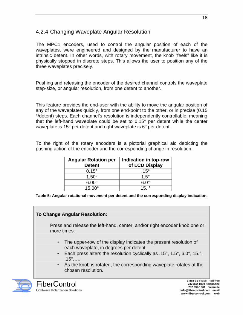
4.2.4 Changing Waveplate Angular Resolution The MPC1 encoders, used to control the angular position of each of the waveplates, were engineered and designed by the manufacturer to have an intrinsic detent. In other words, with rotary movement, the knob “feels” like it is physically stopped in discrete steps. This allows the user to position any of the three waveplates precisely. Pushing and releasing the encoder of the desired channel controls the waveplate step-size, or angular resolution, from one detent to another. This feature provides the end-user with the ability to move the angular position of any of the waveplates quickly, from one end-point to the other, or in precise (0.15 °/detent) steps. Each channel’s resolution is independently controllable, meaning that the left-hand waveplate could be set to 0.15° per detent while the center waveplate is 15° per detent and right waveplate is 6° per detent. To the right of the rotary encoders is a pictorial graphical aid depicting the pushing action of the encoder and the corresponding change in resolution.
Angular Rotation per Detent
Indication in top-row of LCD Display
0.15° .15° 1.50° 1.5° 6.00° 6.0°
15.00° 15. °
Table 5: Angular rotational movement per detent and the corresponding display indication.
To Change Angular Resolution:
Press and release the left-hand, center, and/or right encoder knob one or more times.
• The upper-row of the display indicates the present resolution of each waveplate, in degrees per detent.
• Each press alters the resolution cyclically as .15°, 1.5°, 6.0°, 15.°, .15°,….
• As the knob is rotated, the corresponding waveplate rotates at the chosen resolution.
19
FiberControl Lightwave Polarization Solutions
1-888-91-FIBER toll free 732 332-1860 telephone 732 332-1861 facsimile
[email protected] email www.fibercontrol.com web
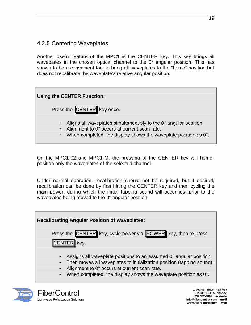
4.2.5 Centering Waveplates Another useful feature of the MPC1 is the CENTER key. This key brings all waveplates in the chosen optical channel to the 0° angular position. This has shown to be a convenient tool to bring all waveplates to the “home” position but does not recalibrate the waveplate’s relative angular position. Using the CENTER Function:
Press the CENTER key once.
• Aligns all waveplates simultaneously to the 0° angular position. • Alignment to 0° occurs at current scan rate. • When completed, the display shows the waveplate position as 0°.
On the MPC1-02 and MPC1-M, the pressing of the CENTER key will home-position only the waveplates of the selected channel. Under normal operation, recalibration should not be required, but if desired, recalibration can be done by first hitting the CENTER key and then cycling the main power, during which the initial tapping sound will occur just prior to the waveplates being moved to the 0° angular position. Recalibrating Angular Position of Waveplates:
Press the CENTER key, cycle power via POWER key, then re-press
CENTER key.
• Assigns all waveplate positions to an assumed 0° angular position. • Then moves all waveplates to initialization position (tapping sound). • Alignment to 0° occurs at current scan rate. • When completed, the display shows the waveplate position as 0°.

20
FiberControl Lightwave Polarization Solutions
1-888-91-FIBER toll free 732 332-1860 telephone 732 332-1861 facsimile
[email protected] email www.fibercontrol.com web
4.2.6 Adjusting Rotational Speed (RATE) The RATE key alters the angular speed in which all the waveplates of the chosen channel move. The MPC1 may be adjusted to move rapidly, or in a slow, smooth progression to the assigned waveplate position. The relationship between the RATE identifier and the angular velocity, in Stokes 3-space, is shown in Figure 7; a convenient tabular form of the graph appears at the end of this section (4.2.6) in Table 6.
RATE Setting vs. Waveplate Rotational Velocity
0
500
1000
1500
2000
2500
3000
3500
0 5 10 15 20 25
RATE Setting
Wav
epla
te R
ota
tio
nal
V
elo
city
, Deg
/sec
Figure 7: RATE value vs. angular velocity of Lefèvre waveplates for the MPC1 series.
For the MPC1-01, pressing the RATE key initiates a menu whereupon, the rotation the right-most encoder, alters the rate value. Higher numeric values represent higher waveplates angular velocities. Conversely, lower values represent slower Lefèvre loop, i.e., waveplate, angular rotation. All three waveplates associated with this channel will have the same angular velocity.

21
FiberControl Lightwave Polarization Solutions
1-888-91-FIBER toll free 732 332-1860 telephone 732 332-1861 facsimile
[email protected] email www.fibercontrol.com web
To adjust the RATE of the MPC1-01:
Push the RATE key once then rotate the right-most encoder to desired
rate, then press CENTER .
• Refer to Figure 7 to correlate rate value setting to angular speed. • Rotating the right-most encoder alters the rate of the channel. • High (Low) rate values correspond to high (Low) angular speed. • Maximum angular rotational speed of any one waveplate is
2880°/sec (in Stokes’ 3-space). • Lowest angular rotational speed of any one waveplate is 20°/sec (in
Stokes’ 3-space). The multi-channel MPC1 series (MPC1-02 and MPC1-M) allow the simultaneous access, on a pair-wise basis, to the individualized adjustment of the RATE values on a per channel basis. For example, with the MPC1-02, in the RATE menu, the left-most encoder alters channel 1 and the right-most encoder alters channel 2. Thus, regardless of which channel the front panel currently controls, when the RATE key is pressed, the menu allows the rates of both corresponding channels to be adjusted. As mentioned earlier, for the MPC1-M, the left display corresponds to channels 1 and 2 while the right display is tied to channels 3 and 4. For that reason, the previous example given for the MPC1-02 is relevant on a pair-wise basis. On all models, exiting the RATE menu by pressing the CENTER key will save the value selected in the RATE menu into nonvolatile memory. It should be noted that the value selected in the RATE menu is automatically recalled each time the MPC1 is powered-up. The rate value can be set from 1 – 20 from the front control panel. This provides an approximate physical angular rotational speed of the waveplate from 10 °/sec (RATE=1) on the low side to 1440 °/sec (RATE=20) on the high side. In the optical domain (when viewed in Stokes’ 3-space), the effective angular velocity is twice the physical rotational velocity, or 2880° per second.
22
FiberControl Lightwave Polarization Solutions
1-888-91-FIBER toll free 732 332-1860 telephone 732 332-1861 facsimile
[email protected] email www.fibercontrol.com web
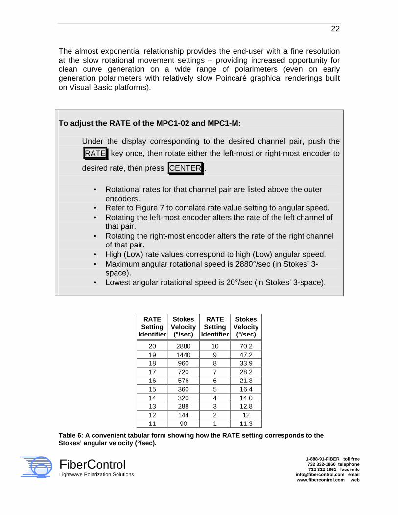
The almost exponential relationship provides the end-user with a fine resolution at the slow rotational movement settings – providing increased opportunity for clean curve generation on a wide range of polarimeters (even on early generation polarimeters with relatively slow Poincaré graphical renderings built on Visual Basic platforms). To adjust the RATE of the MPC1-02 and MPC1-M:
Under the display corresponding to the desired channel pair, push the
RATE key once, then rotate either the left-most or right-most encoder to
desired rate, then press CENTER .
• Rotational rates for that channel pair are listed above the outer
encoders. • Refer to Figure 7 to correlate rate value setting to angular speed. • Rotating the left-most encoder alters the rate of the left channel of
that pair. • Rotating the right-most encoder alters the rate of the right channel
of that pair. • High (Low) rate values correspond to high (Low) angular speed. • Maximum angular rotational speed is 2880°/sec (in Stokes’ 3-
space). • Lowest angular rotational speed is 20°/sec (in Stokes’ 3-space).
RATE Setting
Identifier
Stokes Velocity (°/sec)
RATE Setting
Identifier
Stokes Velocity (°/sec)
20 2880 10 70.2 19 1440 9 47.2 18 960 8 33.9 17 720 7 28.2 16 576 6 21.3 15 360 5 16.4 14 320 4 14.0 13 288 3 12.8 12 144 2 12 11 90 1 11.3
Table 6: A convenient tabular form showing how the RATE setting corresponds to the Stokes’ angular velocity (°/sec).

23
FiberControl Lightwave Polarization Solutions
1-888-91-FIBER toll free 732 332-1860 telephone 732 332-1861 facsimile
[email protected] email www.fibercontrol.com web
4.2.7 Position Memory Preset A valuable feature of the MPC1 is the ability to store pre-set waveplate positions. The MPC1 allows for nine (1 – 9) preset configurations. Any combination of waveplates positions may be quickly saved into non-volatile memory by pressing the SHIFT key and the SAVE key simultaneously. When saving a particular waveplate configuration (desired angular position), the MPC1 requests the selection of a preset memory location (one of nine.) Presets can be conveniently recalled as desired (see section 4.2.8). And, because these settings are stored in non-volatile memory, the MPC1’s power may be cycled without losing the waveplates’ combinatorial positions. Using the Waveplate-Z encoder, select the desired storage location. Selection of the preset from a range of location #1 through location #9 is possible by rotating the encoder. Pressing the CENTER key saves the current waveplate positions into the preset location.
Figure 8: Location of the RECALL, SAVE, and SHIFT keys.

24
FiberControl Lightwave Polarization Solutions
1-888-91-FIBER toll free 732 332-1860 telephone 732 332-1861 facsimile
[email protected] email www.fibercontrol.com web
To SAVE a setting in Memory:
Press and hold the blue SHIFT key then push the SAVE key. Select
memory-stack location using right encoder. Press the CENTER key.
• Stores the present angular location of all waveplates. • Display shows the memory-stack setting. • Select memory-stack by rotating encoder. • Nine (1 - 9) different memory-stack locations are available. • Presets are saved in non-volatile memory.
4.2.8 Recalling Returning to a previously saved combination of angular positions is done in a similar operation to that described under “Saving” (see section 4.2.7). Pressing the RECALL key invokes the Preset menu. To RECALL a Preset from Memory:
Press the RECALL key. Select memory-stack location using right-most
encoder.
• Display shows the memory-stack setting. • Select memory-stack by rotating encoder. • Nine (1 – 9) different memory-stack locations are available. • Presets are saved in non-volatile memory.
You will be prompted, once again, to select the preset of choice by rotating the right-most encoder; and then press the CENTER key to select. On selection, all

25
FiberControl Lightwave Polarization Solutions
1-888-91-FIBER toll free 732 332-1860 telephone 732 332-1861 facsimile
[email protected] email www.fibercontrol.com web
waveplates of the controlled channel will move to the configuration (relative angular orientation) dictated by the preset.
4.2.9 AutoScan Mode
4.2.9.1 AutoScan, Overview The MPC1 is equipped with three AutoScan Mode settings at the local interface: two programmable AutoScan programs and one fixed AutoScan program. The two programmable (user-defined) AutoScan settings provide sequential angular positioning of the paddles and are entered directly at the front-panel (selecting and saving 16 sets of independent positions of the three paddles for that channel). The third, non-programmable AutoScan sequence acts to provide variable speed scrambling functionality (low to medium speed). The channels on the MPC1-02 and MPC1-M operate independently. More specifically, the left channel of the MPC1-02 can be chosen to scramble at any desired rate, from slow to maximum, while the right channel scrambles at its maximum rate.
4.2.9.2 AutoScan Mode, SOP Scramble SOP scrambling functionality is contained within the AutoScan Mode. When Auto Scramble is invoked, a proprietary firmware algorithm initiates and controls the simultaneous movement of each of the three paddles to enhance the number of unique and independent Stokes vectors within a given period of time. The desire is to provide an almost uniform coverage in Stokes’ 3-space – regardless of input SOP. The rate of motion in the scramble mode is controlled by the “RATE” key, or by a similar command issued via a remote interface. Therefore, it is possible to first view and verify the extent of SOP coverage with even early vintage polarimeters by setting the RATE to a slow value – the RATE can then be set to higher values to speed the measurement time, e.g., for PDL evaluation.
26
FiberControl Lightwave Polarization Solutions
1-888-91-FIBER toll free 732 332-1860 telephone 732 332-1861 facsimile
[email protected] email www.fibercontrol.com web
At the maximum motion rate, the repetition period is less than approximately 8 seconds. In other words, it is possible to provide almost uniform coverage in Stokes’ 3-space in less than 8 seconds for PDL test applications. During operation of the Scramble Mode, the progress of the scramble cycle period is indicated on the front-panel LCD display from 0% to 100%. Scramble mode is exited at any time during operation by pressing the AutoScan key.
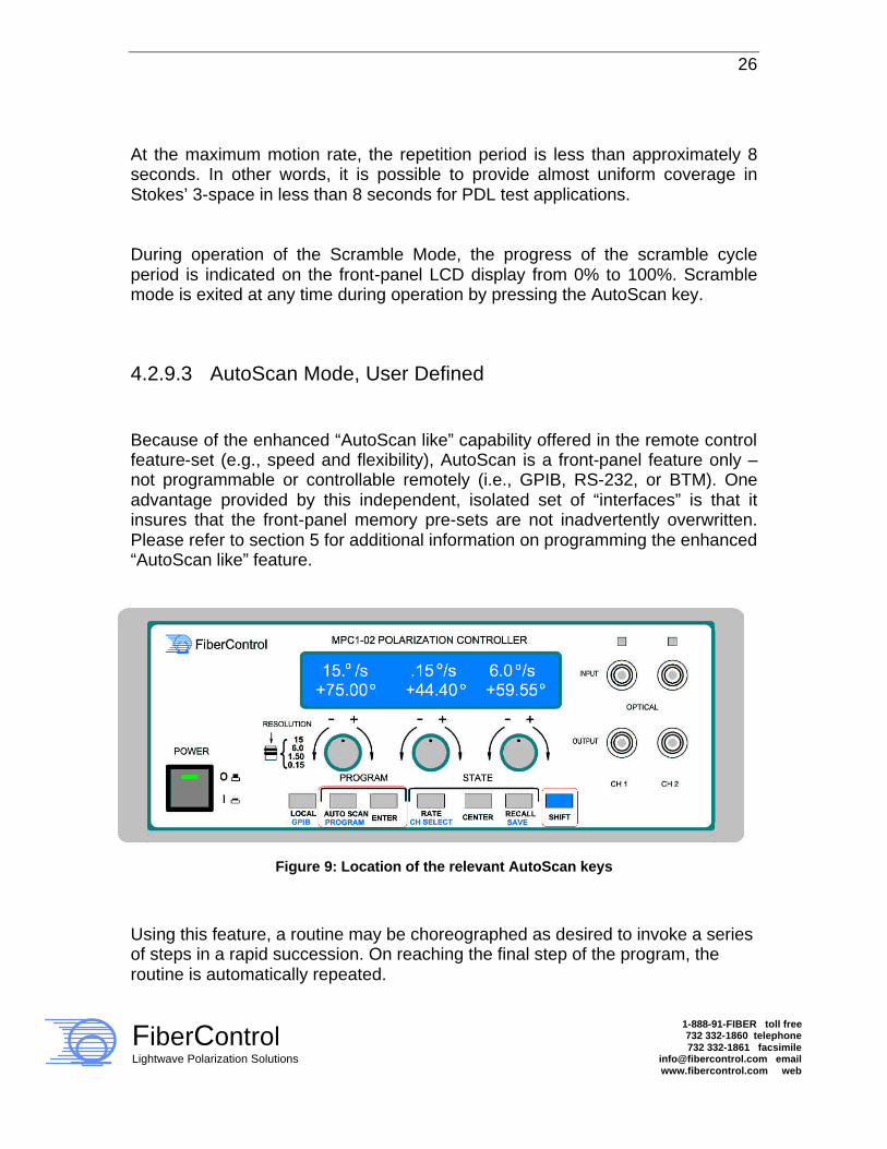
4.2.9.3 AutoScan Mode, User Defined Because of the enhanced “AutoScan like” capability offered in the remote control feature-set (e.g., speed and flexibility), AutoScan is a front-panel feature only – not programmable or controllable remotely (i.e., GPIB, RS-232, or BTM). One advantage provided by this independent, isolated set of “interfaces” is that it insures that the front-panel memory pre-sets are not inadvertently overwritten. Please refer to section 5 for additional information on programming the enhanced “AutoScan like” feature.
Figure 9: Location of the relevant AutoScan keys
Using this feature, a routine may be choreographed as desired to invoke a series of steps in a rapid succession. On reaching the final step of the program, the routine is automatically repeated.

27
FiberControl Lightwave Polarization Solutions
1-888-91-FIBER toll free 732 332-1860 telephone 732 332-1861 facsimile
[email protected] email www.fibercontrol.com web
To activate the AUTOSCAN function:
Press the AUTOSCAN key. Select program by rotating the right encoder.
Press the CENTER key to begin playback of the program of choice.
• Immediately sets into motion the previously programmed sequence. • The sequence repeats continuously. • If no sequence is programmed, no motion occurs as the program
step number cycles. • Waveplate rotational speed is dictated by the current rate setting. • Programs are saved in non-volatile memory. • Cannot be controlled / programmed remotely.
4.2.9.4 Programming and AutoScan Program To begin programming, press the SHIFT key together with the PROGRAM Key. The LCD display will indicate “AutoScan Program” on the top line. The bottom line presents a selection menu of different programs available. Rolling the right-encoder clockwise/counterclockwise changes the selection. When the program of choice is presented on the lower line, press the CENTER key to select. To abort the programming operation, press the AUTOSCAN key a second time. On selection of a user program for alteration, programming of the AutoScan is done via a “Teach” mode. The normal manual waveplate controls are now fully functional. Any waveplate configuration may be selected using the waveplate encoders and the CENTER key. When a desired waveplate position is chosen, the interval (and the respective waveplate position for the interval) may be saved via the ENTER key. The next interval is now available for programming. Throughout the programming process, the LCD display indicates the current program and current interval. During the programming of user programs, the resolution buttons (the pressing in of the encoders) are active; however, the resolution setting is not displayed.

28
FiberControl Lightwave Polarization Solutions
1-888-91-FIBER toll free 732 332-1860 telephone 732 332-1861 facsimile
[email protected] email www.fibercontrol.com web
At any time during the programming procedure, pressing the AutoScan key terminates the process. The current interval is saved, and the AutoScan menu is exited. Thus, it is possible to configure an AutoScan routine to use less than 16 intervals. To do this, configure all intervals that are of interest. Then, program the unwanted intervals to the last valid interval. MPC1 will “skip” all redundant intervals until the AutoScan program is re-cycled. However, the 16 intervals of Program A and Program B cannot be combined into a longer interval sequence larger than 16. For the multi-channel units like the MPC1-02 and MPC1-M, each of the intervals programmed for Program A and Program B are independent, or in other words, channel specific. To program the AUTOSCAN function:
Press and hold the blue SHIFT key then push the PROGRAM key.
Rotate the right encoder to select user program A or user program B.
Press the CENTER key to select a program. Next, program the
waveplates using the front panel controls. Use the ENTER key to
register the each interval. Continue to register intervals, as desired.
• Programmed sequences repeat continuously, therefore, only unique waveplate positions need be set as intervals.
• If no sequence is programmed, no motion occurs. • Each Program has a maximum of 16 intervals, but cannot be
combined into longer interval sequences. • For longer sequences with more independent positions, remote
control can be used. • Waveplate rotational speed is dictated by the current rate setting. • Cannot be controlled / programmed remotely. • Programs are saved in non-volatile memory.
As stated before, because of the enhanced “AutoScan like” capability offered in the remote control feature-set (e.g., speed and flexibility), AutoScan is a front-panel feature only – not programmable or controllable remotely (i.e., GPIB, RS-

29
FiberControl Lightwave Polarization Solutions
1-888-91-FIBER toll free 732 332-1860 telephone 732 332-1861 facsimile
[email protected] email www.fibercontrol.com web
232, or BTM). One advantage provided by this independent, isolated set of “interfaces” is that it insures that the front-panel memory pre-sets are not inadvertently overwritten. Please refer to section 5 for additional information on programming the enhanced “AutoScan like” feature. Since the SOP scrambling capability is hard-coded in the firmware, it cannot be overwritten using with the programming procedure.
4.2.9.5 Example AutoScan program Refer to Appendix A for an example AutoScan program with a detailed explanation.
4.2.9.6 Recalling an AutoScan Program Recalling a previously saved user AutoScan program is initiated by pressing the AUTOSCAN key. A menu is presented which allows three options: Display of available programs, exit of the menu, and selection of a program. Use the right-most encoder to scroll through the program options. Press the Center key to select (play-back) the program. Press the AutoScan key to exit without executing a program. On selection of a user program, execution begins. During each step in the program, the AutoScan execution status (program and interval) is reported on the LCD-display. Each waveplate configuration is attained in rapid succession. It is also notable that the speed in which the AutoScan program is executed is governed by the speed configuration provided by the RATE menu. Hence, it is possible to execute the user-defined AutoScan sequence in a variety of execution speeds. To do this, simply alter the execution rate via the RATE key. This is done outside of the AutoScan execution mode, however.

30
FiberControl Lightwave Polarization Solutions
1-888-91-FIBER toll free 732 332-1860 telephone 732 332-1861 facsimile
[email protected] email www.fibercontrol.com web
4.2.10 Utilities Changing the GPIB address can be done by first pressing the SHIFT key and then the LOCAL key. This invokes the GPIB address menu. In this menu, the encoder for waveplate Z alters the GPIB address. The usable address range is limited to the industry standard range of 1 and 30. It is not necessary to perform the (traditional) re-start of the instrument following a GPIB change. Upon exiting the GPIB alteration menu, the GPIB address is changed immediately. To select the desired address, press the CENTER key. It is not recommended that address 7 be used for the MPC1 since industry standards choose this for the main computer-based controller. The GPIB address will be saved into non-volatile EEPROM memory. To change the GPIB address:
Press and hold the blue SHIFT key then push the LOCAL key. Rotate
the right encoder to set desired address, and then press the CENTER
key.
• Display indicates the address as the right encoder is rotated. • Address range is 1 to 30 (do not choose 7). • Programs are saved in non-volatile memory. • Default address: MPC1-01, MPC1-02 is 4,
MPC1-M is 4 (ch. 1, 2), and 5 (ch. 3, 4).
4.3 Rear-Panel The rear-panel of the MPC1 provides the easy access for connecting line-power via the IEC-320 receptacle in the power entry module.
31
FiberControl Lightwave Polarization Solutions
1-888-91-FIBER toll free 732 332-1860 telephone 732 332-1861 facsimile
[email protected] email www.fibercontrol.com web
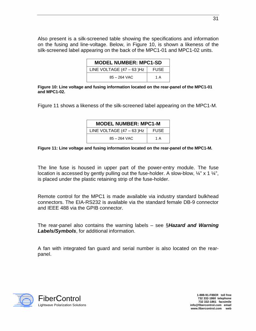
Also present is a silk-screened table showing the specifications and information on the fusing and line-voltage. Below, in Figure 10, is shown a likeness of the silk-screened label appearing on the back of the MPC1-01 and MPC1-02 units.
MODEL NUMBER: MPC1-SD LINE VOLTAGE (47 – 63 )Hz FUSE
85 – 264 VAC 1 A
Figure 10: Line voltage and fusing information located on the rear-panel of the MPC1-01 and MPC1-02.
Figure 11 shows a likeness of the silk-screened label appearing on the MPC1-M.
MODEL NUMBER: MPC1-M LINE VOLTAGE (47 – 63 )Hz FUSE
85 – 264 VAC 1 A
Figure 11: Line voltage and fusing information located on the rear-panel of the MPC1-M.
The line fuse is housed in upper part of the power-entry module. The fuse location is accessed by gently pulling out the fuse-holder. A slow-blow, ¼” x 1 ¼”, is placed under the plastic retaining strip of the fuse-holder. Remote control for the MPC1 is made available via industry standard bulkhead connectors. The EIA-RS232 is available via the standard female DB-9 connector and IEEE 488 via the GPIB connector. The rear-panel also contains the warning labels – see §Hazard and Warning Labels/Symbols, for additional information. A fan with integrated fan guard and serial number is also located on the rear-panel.
32
FiberControl Lightwave Polarization Solutions
1-888-91-FIBER toll free 732 332-1860 telephone 732 332-1861 facsimile
[email protected] email www.fibercontrol.com web
5 Remote Operation: The MPC1 Command Set
5.1 General Initiation of all communications is performed via a remote request by a host computer to the MPC1. On reception of a command either via GPIB or RS-232, the LCD display will indicate the MPC1 has entered remote control mode with a message (i.e., ‘*Remote*’) on the upper line of the display. Further, on the two-channel MPC1, both LED activity indicators will be illuminated. MPC1 will identify the active communications interface when remote mote has been invoked. Further, details of the communications link will be displayed when in remote mode. The MPC1 must be in “idle mode” to initiate a remote request. In the event the MPC1 is running an AutoScan program, or if the instrument is in a configuration menu, commands submitted by the GPIB controller (remote host) will be ignored. It is recommended that individual commands to the MPC1 be given 50ms by the GPIB controller for processing. Hence, a series of individual requests or commands to the MPC1 should be spaced at 50ms intervals to allow for command parsing and processing.
5.1.1 GPIB Configuration In addition to the front panel interface, the MPC1 may be controlled remotely (by a GPIB Controller via the GPIB interface or the RS-232 interface via the DB-9 interface). The core command structure used to communicate with the MPC1 for both interfaces is similar. The GPIB must be configured on the GPIB bus controller. The GPIB Bus controller is typically a PC equipped with a GPIB interface card. The host must

33
FiberControl Lightwave Polarization Solutions
1-888-91-FIBER toll free 732 332-1860 telephone 732 332-1861 facsimile
[email protected] email www.fibercontrol.com web
have a GPIB interface properly installed and interconnects must be made between the MPC1 and the GPIB controller system. The GPIB Address of MPC1 is configured using a "soft switch." The traditional DIP-switch is not necessary for this instrument. To configure the address of MPC1, simply press the SHIFT and the LOCAL keys together on the front panel of MPC1. A menu will appear. Using the right-most encoder, change the MPC1 GPIB address to an address, which is free on the system you are using. To assign the new GPIB address, simply press the CENTER key. This new address will be saved to non-volatile memory for future use. For the MPC1-01 and MPC1-02, the factory default GPIB address is 4. In the case of the MPC1-M, the default GPIB address settings are 4 on channel 1 / channel 2 and 5 on channel 3 / channel 4. For the MPC1-M, two unique GPIB addresses are required. The first left-hand side display’s GPIB address corresponds to Channel 1 and Channel 2; the right-hand side display’s GPIB Address, to Channel 3 and Channel 4. It is important to set each of these GPIB addresses to different values. It is also important to note the "terminating character" or "EOL" character of your GPIB host system. MPC1 requires each command to be terminated with a "Linefeed" otherwise known as the "LF" (ASCII 0x0A) character. It is necessary to configure the host GPIB settings to use "LF" as its command termination character. The typical GPIB transaction begins with a command sent by the GPIB Bus controller, otherwise known as your PC. After receiving the command, the MPC1 will process the request. Requests typically ending in a “?” (“*IDN?”, for example) will invoke MPC1 to respond to the host. Such a transaction will invoke MPC1 to raise the GPIB “RQS” line. It is important that the host should look for this state change. On receiving this indication, the host will “listen” for the response from the MPC1. Failure to do so results in a GPIB bus error and requires a GPIB Device Clear to dismiss.
34
FiberControl Lightwave Polarization Solutions
1-888-91-FIBER toll free 732 332-1860 telephone 732 332-1861 facsimile
[email protected] email www.fibercontrol.com web
An example LabView applet is included on the distribution CD to further illustrate this process. A description of operation will be discussed later in this chapter.
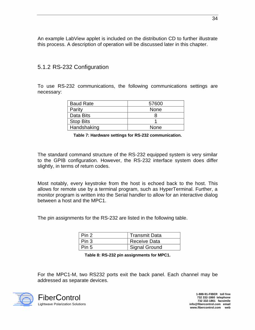
5.1.2 RS-232 Configuration To use RS-232 communications, the following communications settings are necessary:
Baud Rate 57600 Parity None Data Bits 8 Stop Bits 1 Handshaking None
Table 7: Hardware settings for RS-232 communication.
The standard command structure of the RS-232 equipped system is very similar to the GPIB configuration. However, the RS-232 interface system does differ slightly, in terms of return codes. Most notably, every keystroke from the host is echoed back to the host. This allows for remote use by a terminal program, such as HyperTerminal. Further, a monitor program is written into the Serial handler to allow for an interactive dialog between a host and the MPC1. The pin assignments for the RS-232 are listed in the following table.
Pin 2 Transmit Data Pin 3 Receive Data Pin 5 Signal Ground
Table 8: RS-232 pin assignments for MPC1.
For the MPC1-M, two RS232 ports exit the back panel. Each channel may be addressed as separate devices.

35
FiberControl Lightwave Polarization Solutions
1-888-91-FIBER toll free 732 332-1860 telephone 732 332-1861 facsimile
[email protected] email www.fibercontrol.com web
5.2 Command Structure of MPC1 All GPIB Commands must be in ALL CAPS. MPC1 Specific Commands, Synopsis: Paddle Motion
Single Channel MPC1 X=##.## Move waveplate to position nn.nn degrees. Y=##.## Z=##.## CEN Center all waveplates. Multiple Channel MPC1 X1=##.## Move waveplate channel 1 to position nn.nn degrees. Y1=##.## Range: -99.00° -> +99.00°. Z1=##.## X2=##.## Move waveplate channel 2 to position nn.nn degrees. Y2=##.## Range: -99.00° -> +99.00° Z2=##.## CEN1 Center all waveplates on Channel 1 CEN2 Center all waveplates on Channel 2
Paddle Position Inquiry Single Channel MPC1 X? MPC1 returns angular position of respective axis. Y? Z?
Multiple Channel MPC1 X1? MPC1 returns angular position of respective axis of Y1? Channel 1.
Z1?

36
FiberControl Lightwave Polarization Solutions
1-888-91-FIBER toll free 732 332-1860 telephone 732 332-1861 facsimile
[email protected] email www.fibercontrol.com web
X2? MPC1 returns angular position of respective axis of Y2? Channel 2.
Z2?
Paddle Velocity Assignment/Inquiry Single Channel MPC1 RATE=## Assigns speed of motion, channel 1. Range: 1-20. RATE? MPC1 Reports the RATE value for channel 1. Multiple Channel MPC1 RATE1=## Assigns speed of motion, channel A. Range: 1-20.
RATE1? MPC1 reports the RATE value for channel 1.
RATE2=## Assigns speed of motion, channel A. Range: 1-20. RATE2? MPC1 reports the RATE value for channel 2. Auto Mode Invocation
Single Channel MPC1
AUTO=0 Remotely disable all auto modes. AUTO=1 Remotely invoke User Program ‘A’ mode AUTO=2 Remotely invoke User Program ‘B’ mode AUTO=S Remotely invoke scramble mode
Multiple Channel MPC1
AUTO1=0 Remotely disable all auto modes, channel 1 AUTO2=0 Remotely disable all auto modes, channel 2 AUTO1=1 Remotely invoke User Program ‘A’ mode, channel 1 AUTO2=1 Remotely invoke User Program ‘A’ mode, channel 2 AUTO1=2 Remotely invoke User Program ‘B’ mode, channel 1 AUTO2=2 Remotely invoke User Program ‘B’ mode, channel 2 AUTO1=S Remotely invoke scramble mode, channel 1 AUTO2=S Remotely invoke scramble mode, channel 2

37
FiberControl Lightwave Polarization Solutions
1-888-91-FIBER toll free 732 332-1860 telephone 732 332-1861 facsimile
[email protected] email www.fibercontrol.com web
Programming Note:
It is normal convention to PARSE any returned string from the MPC1 after a request is issued either via GPIB or via the serial communications port. The reason for this requirement is that often a returned string from a GPIB device (such as the MPC1) may contain extraneous characters. For instance, a returned string may often contain a space (character 32(d)) and/or the termination string (character 10(d).) The result of a string compare between a raw (unparsed) return string and a test string will therefore fail. For example: If the “OPC?” command is issued via GPIB, the MPC1 will return “1 \n.” It is necessary, therefore, to parse the return string for the desired return code (a “0” or a “1” in this example.) If your development platform is National Instrument’s Labview, a convenient string function is included to “Search within string” for a given sub-string. In Visual Basic or ‘C,’ it is necessary to write a very simple parser to strip away any extra characters, which may be included within the returned string.
5.2.1 Waveplate Motion Control of MPC1 Syntax, Single Channel: X=nn.nn Y=nn.nn Z=nn.nn Syntax, Multiple Channel: Xc=nn.nn Yc=nn.nn Zc=nn.nn This is the position command of the MPC1. Legitimate values assigned to each channel are in the range of – 99.00° - > +99.00°. Keep in mind the resolution of the axis rotation is finite. The step resolution is 0.15°. Hence, the request submitted to MPC1 will be rounded up to the nearest 0.15°.

38
FiberControl Lightwave Polarization Solutions
1-888-91-FIBER toll free 732 332-1860 telephone 732 332-1861 facsimile
[email protected] email www.fibercontrol.com web
The syntax is defined as follows: X,Y,Z defines the axis. ‘c’ defines the channel. Normally this is either ‘1’ or ‘2’. The ‘=’ indicates to MPC1 the command is a channel assignment. Finally, the argument succeeds ‘=’. As a multiple channel MPC1 example, ‘X1=12.15” assigns channel 1, X-axis to angle 12.15°. Likewise, ‘Z2=-22.50’ assigns channel 2, Z-axis to position –22.50°. The same example on a single-channel MPC1: X=12.15 assigns the X-axis to angle 12.15°. Again, ‘Z=-22. 50’ assigns the Z-axis to position –22.50°. For backwards compatibility from the MPC1, multiple channel to the MPC1 single channel, it is legitimate to assign a paddle command with the syntax: ‘X=12.15”. If the channel assignment is not specified, MPC1 will default the value to Channel 1. When the command is issued to MPC1, the axis of choice will immediately begin motion. Subsequent commands may be sent to other waveplates, however an "end of command" character (LF or character 10) must separate each request. If a subsequent assignment is made to a given axis, MPC1 will first complete the current motion assignment before beginning on the next command. For instance, if the following command list is processed: <Y-Axis begins at 0> Y1=99 Y1=-99 MPC1 will process the two, rapid succession commands in the following method: Y will move to position 99°, then immediately begin on the next motion back toward –99°. In other words, MPC1 will not abandon the current motion assignment for a successive move assignment. An important distinction must be made: the MPC1 buffers a single command for each axis. Using again the example recently discussed:
39
FiberControl Lightwave Polarization Solutions
1-888-91-FIBER toll free 732 332-1860 telephone 732 332-1861 facsimile
[email protected] email www.fibercontrol.com web
Y1=99 Y1=-99 Y1=32.5 If the axis is processing the "Y1=99" command, and TWO successive assignments are submitted; MPC1 will honor only the last-most motion assignment. This implies, again using the above example, that Y1=-99 will be OVERWRITTEN by the Y1=32.5 assignment. For rapid-fire motion assignments, it may be wise to make an inquiry from MPC1 to check on the motion status. This may be done via three methods: issue a channel inquiry (X1?, Y1?, Z1?), issue an “OPC?” command, or issue and read the status byte register from the MPC1 via a serial poll. Both of these commands will be described in further detail below.
5.2.2 Inquiry of Axis Position Syntax, Single Channel:
X?
Y? Z? Syntax, Multiple Channel:
Xc? Yc? Zc? This command, when issued, will return the value of each of these axis positions, in degrees. To issue an axis position inquiry on a single-channel MPC1, a two-character command may be submitted. The axis position (in degrees) is reported for Axis X upon the issuance of the command ‘X?’. Likewise, the second and third axis is returned via commands “Y?” and “Z?”, respectively.

40
FiberControl Lightwave Polarization Solutions
1-888-91-FIBER toll free 732 332-1860 telephone 732 332-1861 facsimile
[email protected] email www.fibercontrol.com web
On a multiple channel MPC1, the second character of the position assignment is the channel designator. Hence ‘X1?’ corresponds to a position request for the first axis of channel 1. Likewise, ‘X2?’ corresponds to a position request for the first axis of channel 2. Again, to maintain compatibility to the MPC1 single channel, the omission of a channel on a multi-channel MPC1 indicator sets the inquiry to the default of channel A. The response from MPC1 will be as follows: "S##.##" For example: Command Sent: X? or X1? Response from MPC1: "+ 60.00" Command Sent: Y? or Y1? Response from MPC1: "- 60.00" Command Sent: Z? or Z1? Response from MPC1: "+ 2.40 " If the axis is operating at a very slow rate, it is possible an axis inquiry will provide a response based on the progress of the axis motion. This would be especially evident for very large axis displacement driven at a slow motion rate.
5.2.3 Re-Centering All Waveplates Single Channel Syntax: CEN Multiple Channel Syntax: CEN1 or CEN2 This simply will assign all waveplates to the 0° position.
41
FiberControl Lightwave Polarization Solutions
1-888-91-FIBER toll free 732 332-1860 telephone 732 332-1861 facsimile
[email protected] email www.fibercontrol.com web
The CEN command can be compared to a macro consisting of: X=0, Y=0, and Z=0. On the multiple-channel model, CENA centers channel A, while CEN2 centers channel 2.
5.2.4 Angular Velocity Control of MPC1 Lefèvre Waveplates Single Channel Syntax: RATE=nn Multiple Channel Syntax:
RATE1=nn RATE2=nn
nn= 0 - 20. This value describes the time constant between steps of each axis stepper motor. It is notable the angular velocity value is described using the chart from Figure 2. Caution should be exercised to ensure sufficient settle time for the Lefèvre waveplates after a movement at high speed. Insufficient settle time (or “whip-sawing” the waveplate) may result in the introduction of drift in the waveplate. While such action will not damage MPC1, it could introduce error into the experimental setup. Cycling of power or issuance of a *RST command would be required to correct this, in the event of its occurrence. Settle time is guaranteed by reading the GPIB Status byte from MPC1 following a move assignment. This technique is exemplified in the sample program, Conditional_GPIB_Delay.vi.

42
FiberControl Lightwave Polarization Solutions
1-888-91-FIBER toll free 732 332-1860 telephone 732 332-1861 facsimile
[email protected] email www.fibercontrol.com web
5.2.5 Inquiry of Assigned Rate Single Channel Syntax:
RATE? Multiple Channel Syntax:
RATE1? or RATE2?
MPC1 will return the value assigned to the axis motion velocity constant. The default is maximum speed. It is notable that he RATE value is *not* stored in non-volatile memory when assigned via GPIB or RS-232, as it is through a front-panel assignment.
5.2.6 Remote Invocation of Auto Mode and Scramble Mode Single Channel Syntax: AUTO=n Multiple Channel Syntax: AUTO1=n
AUTO2=n When issued to a single channel MPC1 the AUTO= command initiates or halts a pre-stored user program. As with prior MPC1 commands, the ‘c’ component of the command indicates the channel. Single Channel:
AUTO=0 STOPS all auto programs. AUTO=1 invokes User Program 1 (or ‘A’.) AUTO=2 invokes User Program 2 (or ‘B’.)
AUTO=S invokes SOP scan program. Multiple Channel:

43
FiberControl Lightwave Polarization Solutions
1-888-91-FIBER toll free 732 332-1860 telephone 732 332-1861 facsimile
[email protected] email www.fibercontrol.com web
AUTO1=0 STOPS all auto programs on channel 1. AUTO1=1 invokes User Program 1 (or ‘A’) on channel 1. AUTO1=2 invokes User Program 2 (or ‘B’) on channel 1.
AUTO1=S invokes SOP scan program on channel 1.
AUTO2=0 STOPS all auto programs on channel 2. AUTO2=1 invokes User Program 1 (or ‘A’) on channel 2. AUTO2=2 invokes User Program 2 (or ‘B’) on channel 2.
AUTO2=S invokes SOP scan program on channel 2. It is notable that when any Auto Mode is operating, remote axis assignment commands are “locked-out.” For example, a GPIB axis assignment such as “X1= -90” will be ignored by the MPC1 during the execution of any AUTO1= assignment. Whilst the Auto mode is operating, the Rate value may be changed remotely. This is done via a remote interface by issuing the RATE= (or RATEc= command for multiple channel model MPC1’s.) AUTO=0 or AUTOc=0 disables any operating auto-scan mode. The ability to issue axis position assignments is restored.
5.3 IEEE-488.2 Command Status Support MPC1 Support for Standard IEEE-488.2 Commands:
*IDN? Identifies the instrument *RST Resets MPC1 *STB? Returns status byte *CLS Clears the status byte *STR=n Sets status byte mask to n *SRE? Inquires status byte mask from MPC1 *ESR? Returns status register contents from MPC1 *ESE=n Sets the status register mask to n. *ESE? Reports mask setting of status register. *TST? Reports result from Self-Test

44
FiberControl Lightwave Polarization Solutions
1-888-91-FIBER toll free 732 332-1860 telephone 732 332-1861 facsimile
[email protected] email www.fibercontrol.com web
The following standard commands are supported by MPC1 to maintain compatibility with the IEEE 488.2 command set: Traditionally, the asterisk (*) is used before each IEEE 488.2 command. MPC1 accepts IEEE-488.2 commands both with and without the leading asterisk. CLS - Clears status byte to default of MPC1 when issued by host to MPC1 OPC? - Operation Complete query. MPC1 responds with 1 or 0. 1 (ASCII 49) = Operation COMPLETE. 0 (ASCII 48) = Operation NOT COMPLETE. The OPC inquiry is an excellent method for handshaking a series of movement commands. When a motion command is submitted to MPC1, it is wise to poll the MPC1 via the “OPC?” inquiry. When “OPC?” returns a “1,” a subsequent motion command can be sent to MPC1.
5.3.1 Status Byte Register Control Mechanisms SRE=n: This is the Status Byte mask assignment. The SRE command expects a mask value in decimal. The valid range of values is SRE=0 -> SRE=255. This command is very closely tied to the STB? Command. Further operational specifics are outlined in the STB? Command explanation. STB? – Displays the contents of status byte as a decimal value. This command performs a similar function to a Serial Poll. However, unlike the Serial Poll response, the STB? Applies the mask specified by the SRE= command. The response is an eight-bit byte containing a pattern describing the instrument status. For the MPC1 the status byte describes whether the MPC1 is busy, whether an error has occurred, or whether the MPC1 is "listening" or "talking."

45
FiberControl Lightwave Polarization Solutions
1-888-91-FIBER toll free 732 332-1860 telephone 732 332-1861 facsimile
[email protected] email www.fibercontrol.com web
Status Byte Bit Assignments: B7 B6 B5 B4 B3 B2 B1 B0
Table 9: Standard IEEE 488.2 status byte bit assignments.
In Table 10, additional information is provided explaining the bit assignments. BIT VALUE COMMENTS B7 Always ZERO B6 RQS bit It is set and cleared internal to the MPC1. The purpose
of this bit is to indicate to the controller if data is ready for transmission from the MPC1 to the controller (PC.) This bit is unable to be masked.
B5 Error Indicator B4 MAV This bit is automatically handled by MPC1 to indicate to
the GPIB controller if the output buffer contains characters to transmit.
B3 Always ONE B2 Always ONE B1 Always ONE B0 Busy Status 1 = Axis in motion, 0 = Axis idle
Table 10: Detailed IEEE-488.2 bit assignments.
As an example, reading the status of the busy indicator bit may be done using the following procedure. (This function, incidentally, is very similar to reading the response to the query "OPC?"). First, Set the Status bit mask, or the SRQ: "SRE=1" Explanation: The SRE value, which is passed in this command represents the bit pattern (MSB) 0000 0001 (LSB) = decimal 65) for which to mask the status byte. A mask to bit on B6 is ignored, as is provides request information to the GPIB host. Bit B0 is the "Busy Status" bit. It is set high (1) when the MPC1 is busy and it is set low (0) when it the MPC1 is idle.

46
FiberControl Lightwave Polarization Solutions
1-888-91-FIBER toll free 732 332-1860 telephone 732 332-1861 facsimile
[email protected] email www.fibercontrol.com web
Following the SRE=1 assignment, subsequent STB? inquiries will either provide a response of the following states (all values in HEX): 0 (dec), 0x00 (hex), 0000 0000 (binary) = (MPC1 is in READ mode (B6=0) and NOT Busy (B0=0)) 1 (dec), 0x01(hex), 0000 0001(binary) = (MPC1 is in READ mode (B6=0) and Busy (B0=1)) 64 (dec), 0x40(hex), 0100 0000 (binary) = (MPC1 is in WRITE mode (B6=0) and NOT Busy (B0=0)) 65 (dec), 0x41(hex), 0100 0001(binary) = (MPC1 is in WRITE mode (B6=0) and Busy (B0=1)) In the application program executing on the GPIB Controller, only bit B0 of the status byte is of interest. It is hence possible to mask the Serial Poll response with hex 0x01 and perform a Boolean test for only B0. Based on the test of bit B0, the application program can test whether MPC1 has completed a command request. SRE? - Reports the SRE Mask. The default mask is 255(dec) (0xff). After an assignment to SRE, the mask value may be confirmed by an SRE? Request.
5.3.2 Event Standard Register Control Mechanisms ESR? - Reports the Event Status Register. As follows are the bit assignments of this register: <MSB> B7 B6 B5 B4 B3 B2 B1 B0 <LSB> B7=Incomplete READ B6=Incomplete WRITE B5=System Error B4=USER INPUT error B3,2,1,0: Not Used by MPC1, always 0. The ESE command is a mask value applied to the Event Standard Register Control to the Status Byte.

47
FiberControl Lightwave Polarization Solutions
1-888-91-FIBER toll free 732 332-1860 telephone 732 332-1861 facsimile
[email protected] email www.fibercontrol.com web
ESE=<dec value> SETS the mast. The system default is 255 (0xff hex). Unless a specific need is identified, it is recommended to NOT change this value. ESE? Reports the mask setting. IDN? - Queries MPC1 for identification. The response will identify the product and the firmware revision. RST - Performs a cold reset to the MPC1. TST? - Performs a brief self-test and reports general configuration. In the event an internal error is detected, an error code is presented. Else, a result code is presented to indicate normal operation and configuration. In the event an error code is reported, contract FiberControl for assistance.
5.4 MPC1 GPIB Remote Programming On the distribution CD, you will find a few application files written for the MPC1 in the National Instruments LabView programming environment. This section will attempt to explain how and why the techniques used in the application programs were used. Further, the “sub-VI” components have been written modularly, allowing for quick reuse into you own laboratory applications. Each significant MPC1 detail will be explained in the following text: PADDLE_CYCLE_1_SINGLE.vi PADDLE_CYCLE_1_MULTI.vi: This mini application simply moves each Lefèvre waveplate in a round-robin fashion. The significant aspect of this program is the operation of MPC1 in a “closed control loop” fashion.
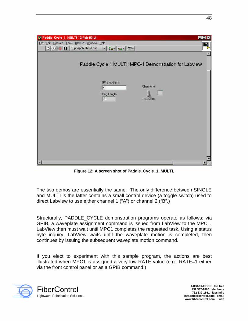
48
FiberControl Lightwave Polarization Solutions
1-888-91-FIBER toll free 732 332-1860 telephone 732 332-1861 facsimile
[email protected] email www.fibercontrol.com web
Figure 12: A screen shot of Paddle_Cycle_1_MULTI.
The two demos are essentially the same: The only difference between SINGLE and MULTI is the latter contains a small control device (a toggle switch) used to direct Labview to use either channel 1 (“A”) or channel 2 (“B”.) Structurally, PADDLE_CYCLE demonstration programs operate as follows: via GPIB, a waveplate assignment command is issued from LabView to the MPC1. LabView then must wait until MPC1 completes the requested task. Using a status byte inquiry, LabView waits until the waveplate motion is completed, then continues by issuing the subsequent waveplate motion command. If you elect to experiment with this sample program, the actions are best illustrated when MPC1 is assigned a very low RATE value (e.g.: RATE=1 either via the front control panel or as a GPIB command.)

49
FiberControl Lightwave Polarization Solutions
1-888-91-FIBER toll free 732 332-1860 telephone 732 332-1861 facsimile
[email protected] email www.fibercontrol.com web
Specifics of operation entail the following: Step 1: Execution of a cycle begins with a “read” of the toggle switch. Based on the Boolean condition of this switch, commands will be sent to either channel A or to channel B. Step 2: A command string is assembled and dispatched via GPIB to the MPC1. Notice the “String Concatenate” function is used to add a necessary LF (Line Feed) to the end of the MPC1 command. When the command is assembled, it is dispatched through the GPIB interface for processing by the MPC1.
Figure 13: Annotated string assembly for delivery to the GPIB port in Labview. This string
concatenation is from the single channel version of MPC1.
Step 2 will prompt MPC1 to begin moving the first Lefèvre waveplate to – 99°.
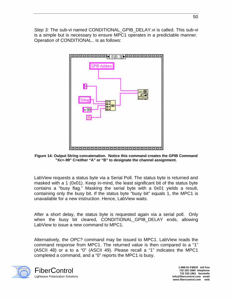
50
FiberControl Lightwave Polarization Solutions
1-888-91-FIBER toll free 732 332-1860 telephone 732 332-1861 facsimile
[email protected] email www.fibercontrol.com web
Step 3: The sub-vi named CONDITIONAL_GPIB_DELAY.vi is called. This sub-vi is a simple but is necessary to ensure MPC1 operates in a predictable manner. Operation of CONDITIONAL.. is as follows:
Figure 14: Output String concatenation. Notice this command creates the GPIB Command
"Xc=-99" C=either “A” or “B” to designate the channel assignment.
LabView requests a status byte via a Serial Poll. The status byte is returned and masked with a 1 (0x01). Keep in-mind, the least significant bit of the status byte contains a “busy flag.” Masking the serial byte with a 0x01 yields a result, containing only the busy bit. If the status byte “busy bit” equals 1, the MPC1 is unavailable for a new instruction. Hence, LabView waits. After a short delay, the status byte is requested again via a serial poll. Only when the busy bit cleared, CONDITIONAL_GPIB_DELAY ends, allowing LabView to issue a new command to MPC1. Alternatively, the OPC? command may be issued to MPC1. LabView reads the command response from MPC1. The returned value is then compared to a “1” (ASCII 48) or a to a “0” (ASCII 49). Please recall a “1” indicates the MPC1 completed a command, and a “0” reports the MPC1 is busy.

51
FiberControl Lightwave Polarization Solutions
1-888-91-FIBER toll free 732 332-1860 telephone 732 332-1861 facsimile
[email protected] email www.fibercontrol.com web
If MPC1 is busy, the sub-vi will re-cycle by waiting 50-100ms then re-test via a subsequent OPC? query. If the MPC1 reports the command is completed (a “1”), it is now safe to issue another move request to the MPC1. Please note it is a wise approach to parse the return string for a return value. Depending on the GPIB implementation on the host, other characters may be received with the return string. LabView conveniently provides the Match TRUE/FALSE String function to perform this functionality. Subsequent motion steps employ a similar structure. A motion request is issued by the GPIB Controller (LabView running on a PC) and the MPC1 is polled to indicate the task is completed. Given the ability to use either method, the “serial poll” method is far superior to the OPC? method. The reason is as follows: issuing a Serial Poll and reading the status byte is very rapid. The GPIB bus is not “cluttered” by the traffic required to transmit the OPC? command and response. The performance of your application will benefit as a result. Further, the serial poll method is easier to implement in LabView. In a larger application, it is recommended the time used to wait for MPC1 to complete a command be used to do another task. It is unnecessary to wait in a “tight loop” for the MPC1 to complete its motion assignment. For instance, during the time MPC1 is moving a waveplate, it would be a good interval to take measurements, make calculations, etc.
Programming Note: The use of sub-vi CONDITIONAL_GPIB_DELAY.vi is recommended in Labview applications to form efficient GPIB handshaking between the host and the MPC1.
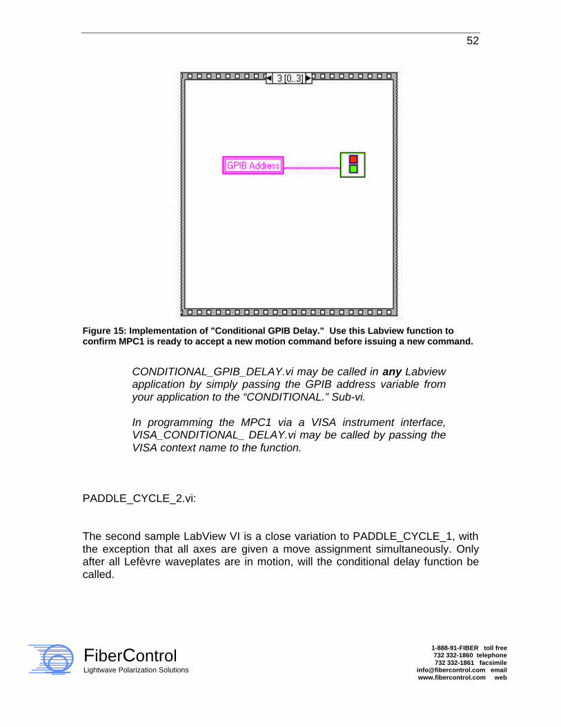
52
FiberControl Lightwave Polarization Solutions
1-888-91-FIBER toll free 732 332-1860 telephone 732 332-1861 facsimile
[email protected] email www.fibercontrol.com web
Figure 15: Implementation of "Conditional GPIB Delay." Use this Labview function to confirm MPC1 is ready to accept a new motion command before issuing a new command.
CONDITIONAL_GPIB_DELAY.vi may be called in any Labview application by simply passing the GPIB address variable from your application to the “CONDITIONAL.” Sub-vi. In programming the MPC1 via a VISA instrument interface, VISA_CONDITIONAL_ DELAY.vi may be called by passing the VISA context name to the function.
PADDLE_CYCLE_2.vi: The second sample LabView VI is a close variation to PADDLE_CYCLE_1, with the exception that all axes are given a move assignment simultaneously. Only after all Lefèvre waveplates are in motion, will the conditional delay function be called.

53
FiberControl Lightwave Polarization Solutions
1-888-91-FIBER toll free 732 332-1860 telephone 732 332-1861 facsimile
[email protected] email www.fibercontrol.com web
To further illustrate operation: Step 1: Lefèvre waveplate X is given an assignment of –99°, Y = -99°, and Z=-99° via the LabView GPIB-Out command. All waveplates begin moving. Notice each command is separated by a short (~ 50ms to 70ms) delay. This is recommended in any situation where multiple commands are rapidly issued. Step 2: CONDITIONAL_GPIB_DELAY is again called. Execution is delayed until ALL axes have arrived to their final position. Step 3: All waveplates are again given a new assignment. All waveplates move again. This second example provides more efficient movement to a new SOP by ganging many axes together to perform three discreet motion commands as a single movement. VISA_CONDITIONAL.vi; VISA_PADDLE_CONTROL_1.vi: This is a simple variation of aforementioned example Labview applications, which employ a Labview VISA interface, rather than the direct-GPIB access approach. This is a reference example of addressing MPC1 using the VISA method, if this is your programming preference. MPC1_INTERACTIVE_CONTROL.vi: This example program illustrates a method of user-input to control the MPC1 remotely. The example provides a simple user-interface with a “conveyance layer” to format LabView control output into a MPC1 angle assignment command, then transfer the request to the MPC1. The interactive example application employs the same hold-until-complete sub-vi as used in prior examples.

54
FiberControl Lightwave Polarization Solutions
1-888-91-FIBER toll free 732 332-1860 telephone 732 332-1861 facsimile
[email protected] email www.fibercontrol.com web
Figure 16: A screen shot of MPC1 Interactive control.
Either of these methods may be employed, as your application dictates. MPC1_READ_FRAGMENT.vi: The final example applet describes a desirable method for reading a response from the MPC1. MPC1_Read_Fragment simply issues a request to MPC1, and then listens for a response from the instrument. The applet begins by sending a request to the MPC1 by the GPIB Controller. The command sent is “*IDN?” (Identify). MPC1 responds by identifying itself along with its Firmware revision code.

55
FiberControl Lightwave Polarization Solutions
1-888-91-FIBER toll free 732 332-1860 telephone 732 332-1861 facsimile
[email protected] email www.fibercontrol.com web
Enclosed is a screen dump of the “business end” of the applet:
Figure 17: LabView core code for receiving and transmitting to MPC1. Notice the bus arbitration performed via the “wait for RQS” command (item C.)
Notice four distinct items. Each will be explained in detail, as this mechanism may be mimicked within your own application. ‘Item A’ concatenates the “*IDN?” request with the necessary terminator, a linefeed (ASCII 10). The output of the concatenate function is piped to the GPIB send function.
56
FiberControl Lightwave Polarization Solutions
1-888-91-FIBER toll free 732 332-1860 telephone 732 332-1861 facsimile
[email protected] email www.fibercontrol.com web
‘Item B’ transmits the command via GPIB to the MPC1. There are two items of interest in this frame. First, notice the GPIB address is hard-coded. This may not suffice in your application. It has been done this way only for clarity. Secondly, notice the function is devoid of a “Mode” assignment. The default mode is correct (0). If you have any question about these particulars, you may wish to consult with the LabView documentation. ‘Item C’ is the “bus arbitration’ of the GPIB transaction. This is a “wait for the RQS” indicator. On receiving the RQS signal (a GPIB bus signal line being toggled from high to low, the GPIB Controller (the PC) is informed that it is time to receive. ‘Item D’ is the Receive function. Once the RQS signal is raised, it is necessary to receive the incoming packet from the MPC1. It should be stressed that this is the “conservative” approach to communicating to any instrument via GPIB. Further, a parallel scheme is available using the optional VISA abstraction layer within LabView. Each command issued in this example has an identical VISA counterpart. Finally, this same general approach may be used when communicating to MPC1 using Visual Basic or ‘C’ via a GPIB programming API. The GPIB API for VB or C use these approximate equalities: C/VB: ibdev() = (LabView) VISA OPEN C/VB: ibwrt() = (LabView) GPIB WRITE C/VB: ibwait() = (LabView) GPIB WAIT RQS C/VB: ibread() = (LabView) GPIB READ Further information on the C/VB GPIB API is available from your GPIB card vendor.

57
FiberControl Lightwave Polarization Solutions
1-888-91-FIBER toll free 732 332-1860 telephone 732 332-1861 facsimile
[email protected] email www.fibercontrol.com web
5.5 MPC1 Serial (RS-232) Remote Programming Serial support on the MPC1 includes the same command set provided to GPIB, with a few additions: 1. A monitor program is provided by MPC1 to allow remote control via a terminal
program such as Microsoft’s HyperTerminal. Using any PC-based terminal utility, the command set described in section three. The serial monitor program has been configured to provide echo-back and line-command correction.
2. When using Serial mode, an ACK character is dispatched on completion of a
waveplate motion command. This ACK character (character ascii 6) is issued on completion of a motion command and MPC1 returns to the “idle” state. To clarify, if three successive motion commands are issued to MPC1 axis X, axis Y, and axis Z; an ACK will be submitted on completion of all motion. Hence, the host computer in this situation should expect only a single ACK-character.
It is important to note an illegitimate move command will not return an ACK. For example, a command intended to move a waveplate to a position in which the waveplate already resides produces no ACK response. In the event of optical measurement equipment integration, the ACK may be used to presume the settlement of MPC1 after a motion assignment’s execution. In doing so, measurement equipment within the optical circuit may sample on reception of an ACK.
It is notable that HyperTerminal displays the ACK character as a playing-card “spade.”
Programming Note: When programming the MPC1 via the RS232 port in “normal mode,” handshaking may be handled in one of three direct methods:

58
FiberControl Lightwave Polarization Solutions
1-888-91-FIBER toll free 732 332-1860 telephone 732 332-1861 facsimile
[email protected] email www.fibercontrol.com web
a. You may monitor the progress of an MPC1 motion assignment by monitoring for the ACK character, which MPC1 issues at the conclusion of each move.
b. You may issue an “OPC?” command and parse the return code of either a “0” or a “1.” Please remember that if you elect not to use a handshaking method, use care when designing a delay mechanism to ensure assignment intervals are not overwritten.
3. MPC1 supports a special binary mode, which is known to the MPC1 as
“Transparent Communications Mode.” This mode is supported by the RS-232 interface only. Usage of the Transparent mode to control MPC1 allows for extremely rapid communications for the purpose of “leveling the score” between RS-232 and GPIB control. The transparent mode will be described in greater detail later in this section.
In general, the MPC1 can be controlled serially in LabView or any other program using a similar architecture to those outlined under the GPIB subsection. The programmer may find it convenient to use the ACK handshaking features of the RS-232 easier to implement than reading the OPC? command. It is notable that because of the serial monitor user interface, and the echo-back features of the monitor program, it is necessary to PARSE for the return codes from MPC1. To clarify, it is necessary for the programmer to process a line of returned text from MPC1 to “pick-out” the return value from surrounding text.
5.6 MPC1 Binary Transparent Mode Remote Programming Transparent mode utilizes a SEND ONLY structure, which compresses an abbreviated command set into two bytes for transmission to the MPC1. Using this technique, very rapid motion movements may be made between an application program and the MPC1.

59
FiberControl Lightwave Polarization Solutions
1-888-91-FIBER toll free 732 332-1860 telephone 732 332-1861 facsimile
[email protected] email www.fibercontrol.com web
After every Motion request which is processed; the ACK character is transmitted in exactly the same manner described earlier in this section. Sample command encapsulation ‘C’ source code is also published later in this section. The Transparent mode is entered via a serial standard mode command “TR.” MPC1 will prevent the processing of the TR command via GPIB. Exiting transparent mode can occur via one of three ways:
1. The LOCAL key is pressed, 2. The power is cycled on the MPC1, 3. Transparent mode is exited via a command sent by the host computer to
the MPC1. The two-byte command should better be described as a single, 16-bit value; albeit broken into two 8-bit characters. The general format is as follows: <MSB> 76543210 76543210 <LSB> <MSB> AABB1CCC DDDDDDDD <LSB> Leading (first) byte transmitted by host is: “AABB1CCC” Trailing (second) byte transmitted by host is: “DDDDDDDD” In the bit-sequence: “AA” represents the command, “BB” represents the CHANNEL. Further, “CCCDDDDDDDD” represents the VALUE. Notice the VALUE is “framed” by 1’s. This is critical. MPC1 uses a delimiting “1” as a sanity-check on transmission of a command. If the host computer transmits a command without bit position Byte 0, bit 3=1, the command is discarded.
60
FiberControl Lightwave Polarization Solutions
1-888-91-FIBER toll free 732 332-1860 telephone 732 332-1861 facsimile
[email protected] email www.fibercontrol.com web
5.6.1 Issuing a Motion Command in Transparent Mode The following command structure is used: <MSB> 76543210 76543210 <LSB> <MSB> AABB1CCC DDDDDDDD <LSB> AA=00 BB=Channel:
00=X 01=Y 10=Z 11=<reserved> CC..DD= 11-bit absolute position in steps. A very important distinction between the transparent mode and the standard command mode is the transparent mode motion commands are issued in STEPS – not degrees. To elaborate on the step-assignment value, MPC1 employs a micro-stepping scheme to provide a total of 2400 steps per full motor revolution. The active range of the MPC1 paddles is 198° (– 99° - > + 99°). As the step resolution is 0.15° per step provides a product of 1320 total steps within the assignable range. The origin of each Lefèvre waveplate is as follows: step 0 = – 99°. The maximum position, or + 99° is step position 1320. Hence, every value sent in transparent mode must make the degree-to-step conversion. This is stated as: Step Position # = {Step angle (in degrees) + 99°} / 0.15 °per step. To calculate step position +22.5°, the result formula is: (22.5° + 99°) / (0.15°/step) = 202.5 =(approx) 810 steps.

61
FiberControl Lightwave Polarization Solutions
1-888-91-FIBER toll free 732 332-1860 telephone 732 332-1861 facsimile
[email protected] email www.fibercontrol.com web
810 steps = 0x032A (hex) = 0000 0011 0010 1010 (16-bit binary). This truncates to an 11-bit value of (binary) 011 0010 1010. Taking, for instance, the assignment of axis X to position 22.5°. Encapsulating this value into a transparent command: AA=00 (the move command) BB=Channel=00 for axis X CCCDDDDDDDD= 011 0010 1010 = absolute position value A mandatory “1” bit in bit position 3 of the most significant byte is used to frame the command. To clarify this point the full 16-bit command is: AABB1CCC DDDDDDDD. (Byte 0:) 00001011 (Byte 1:)0010 1010 Byte 0: 0x0B Byte 1: 0x2A As a second Example, to issue a command to the Z-axis for an angle of –45’: (-45 degrees + 99 degrees) / 0.15 (deg/step) = 360 steps. As a 16-bit binary value, 90 steps is represented as 0000 0001 0110 1000. As we are interested only in an 11-bit value, truncation is necessary. Our original value of 360 value is hence reduced to 001 0110 1000. AA=00 (the move command) BB=10 (Paddle Z = axis 2 = binary 10) CCCDDDDDDDD=001 0110 1000=absolute position value Framing the CCCDDDDDDDD with the leading “1” and combining: (Byte 0)=0010 1001 (Byte 1)=0110 1000 Byte 0 = 0x29, Byte 1 = 0x68

62
FiberControl Lightwave Polarization Solutions
1-888-91-FIBER toll free 732 332-1860 telephone 732 332-1861 facsimile
[email protected] email www.fibercontrol.com web
5.6.2 Issuing a RATE Change command in Transparent Mode The following command structure is used: <MSB> 76543210 76543210 <LSB> <MSB> AABB1CCC DDDDDDDD <LSB> AA=10 BB=11 CCCDDDDDDD=LOWER 8-bits represent the speed constant. <MSB> 76543210 76543210 <LSB> <MSB> 10111XXX DDDDDDDD<LSB> Valid values for value for RATE is 0->254. As an example, to set the rate to 128: AA=10 BB=11 CCC = Don’t Care (X) DDDDDDDD = 1000 0000 = 0x80 (Hex) Assembling this into a structure with “1’s” framing the value portion: Byte 0=1011 1000; Byte 1=1000 0000 Byte 0= 0xb8; Byte 1=0x80
5.6.3 Exiting Transparent Mode The following command structure is used: <MSB> 76543210 76543210 <LSB> <MSB> AABB1CCC DDDDDDDD <LSB> AA=11 BB=10
63
FiberControl Lightwave Polarization Solutions
1-888-91-FIBER toll free 732 332-1860 telephone 732 332-1861 facsimile
[email protected] email www.fibercontrol.com web
CCCDDDDDDDD=Don’t care. Once again, a “1” bit must be placed between AABB and CC..DD. (eg. AABB1CCC DDDDDDDD.) Example, to exit Transparent Mode, issue the following command: 11101000 00000000 Byte 0= 0xe8, Byte 2=0x00 As in standard RS-232 command mode, an ACK is sent by MPC1 to the host on completion of any motion command. In transparent command mode, the programmer may elect to either ignore handshaking, or to process the ACK command when each motion has completed.

64
FiberControl Lightwave Polarization Solutions
1-888-91-FIBER toll free 732 332-1860 telephone 732 332-1861 facsimile
[email protected] email www.fibercontrol.com web
Appendix A: Instructional Program, Example AutoScan Code
Provided below, in tabular form, is an example AutoScan program. It shows the entry of the corresponding commands at each interval to produce the desired paddle angular orientation.
Interval Waveplate X Waveplate Y Waveplate Z
1 45° -62.6° 0° 2 25° 22.5° 90° 3 20° 0° -99°
4 – 16 45° 45° 45° In the above example, the MPC1 will execute Interval 1, 2, 3, and 4 sequentially. Because Intervals 5 through 16 are not assigned, the program skips those intervals and rapidly re-cycle the program back to Interval 1.

65
FiberControl Lightwave Polarization Solutions
1-888-91-FIBER toll free 732 332-1860 telephone 732 332-1861 facsimile
[email protected] email www.fibercontrol.com web
Appendix B: LabView® Driver, Example GPIB and RS-232 Code
– Please refer to Distribution CD –

66
FiberControl Lightwave Polarization Solutions
1-888-91-FIBER toll free 732 332-1860 telephone 732 332-1861 facsimile
[email protected] email www.fibercontrol.com web
Appendix C: Instructional Program, Example Binary Transparent Mode Code
Finally, to illustrate a “packing” scheme, as follows is a Win32 code fragment to perform such transparent mode serial encapsulation. This ‘C’ function is passed a channel and a command. The function will output (via the WriteFile command,) the packed command to the RS-232 interface.
BOOL TransmitCommand(char cCommand,char cChannel, unsigned int uiValue) { DWORD dwWritten; DWORD dwToWrite=3; unsigned char cCommString[4]; static int tempy; unsigned short int scratch; /* 16-bit variable*/ scratch = 0x0000; // init scratch. Play safe. scratch |= cCommand; // scratch = xxxx xxxx xxxx xxCC scratch <<= 2; // scratch = xxxx xxxx xxxx CCxx scratch |= cChannel; // scratch = xxxx xxxx xxxx CCBB scratch <<= 1; // scratch = xxxx xxxx xxxC CBBx scratch |= 0x0001; // scratch = xxxx xxxx xxxC CBB1 scratch <<= 11; // scratch = CCBB 1xxx xxxx xxxx uiValue=uiValue & 0x07ff; /* ..Interested in xxxx x111 1111 1111 (11-bit value)*/ scratch = scratch | uiValue; // scratch = CCBB 1vvv vvvv vvvv cCommString[0] = HIBYTE(scratch); //CommString[0] = CCBB1vvv cCommString[1] = LOBYTE(scratch); //CommString[1] = vvvvvvv1 cCommString[2] = 0x00; //Delimit character. WriteFile(hComm, cCommString, dwToWrite, &dwWritten, &PortInfo.osWrite); return TRUE; }

67
FiberControl Lightwave Polarization Solutions
1-888-91-FIBER toll free 732 332-1860 telephone 732 332-1861 facsimile
[email protected] email www.fibercontrol.com web
Appendix D: Front-Panel Quick Reference To Power-up the MPC1:
Attach provided power cord by mating C13 plug to the MPC1’s IEC-320
receptacle, then insert plug end into line power, and push the POWER
key once.
• Integrated green LED will light. • All waveplates simultaneously align to the last known position. • Very light tapping sound may be heard during waveplate
initialization. To Power-down the MPC1:
Push the POWER key once.
• The once lighted integrated green LED will dim slowly over a few
seconds until dark. • The display(s) backlight dims and the alphanumeric information
fades until the overall display(s) becomes dark blue. Using the LOCAL Function:
Press the LOCAL key once.
• Decouples the MPC1 channel or channel pair from remote GPIB
control and ensures control of the front-panel. • Display now shows waveplate angular position in degrees and
resolution setting. • Each encoder now controls the angular orientation of its
corresponding waveplate. • Immediately stops the last remote command and leaves all
waveplates at the last angular position.

68
FiberControl Lightwave Polarization Solutions
1-888-91-FIBER toll free 732 332-1860 telephone 732 332-1861 facsimile
[email protected] email www.fibercontrol.com web
To Change Angular Resolution:
Press and release the left-hand, center, and/or right encoder knob one or more times.
• The upper-row of the display indicates the present resolution of each waveplate, in degrees per detent.
• Each press alters the resolution cyclically as .15°, 1.5°, 6.0°, 15.°, .15°,….
• As the knob is rotated, the corresponding waveplate rotates at the chosen resolution.
Using the CENTER Function:
Press the CENTER key once.
• Aligns all waveplates simultaneously to the 0° angular position. • Alignment to 0° occurs at current scan rate. • When completed, the display shows the waveplate position as 0°.
Recalibrating Angular Position of Waveplates:
Press the CENTER key, cycle power via POWER key, then re-press
CENTER key.
• Assigns all waveplate positions to an assumed 0° angular position. • Then moves all waveplates to initialization position (tapping sound). • Alignment to 0° occurs at current scan rate. • When completed, the display shows the waveplate position as 0°.
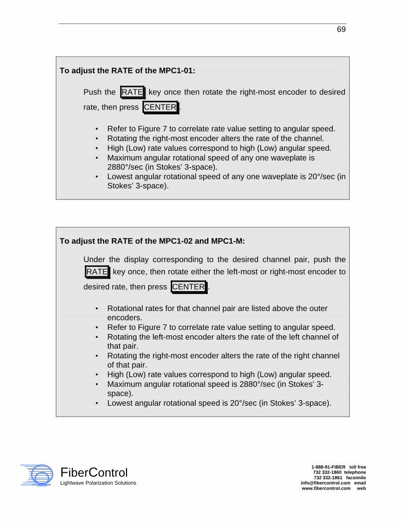
69
FiberControl Lightwave Polarization Solutions
1-888-91-FIBER toll free 732 332-1860 telephone 732 332-1861 facsimile
[email protected] email www.fibercontrol.com web
To adjust the RATE of the MPC1-01:
Push the RATE key once then rotate the right-most encoder to desired
rate, then press CENTER .
• Refer to Figure 7 to correlate rate value setting to angular speed. • Rotating the right-most encoder alters the rate of the channel. • High (Low) rate values correspond to high (Low) angular speed. • Maximum angular rotational speed of any one waveplate is
2880°/sec (in Stokes’ 3-space). • Lowest angular rotational speed of any one waveplate is 20°/sec (in
Stokes’ 3-space). To adjust the RATE of the MPC1-02 and MPC1-M:
Under the display corresponding to the desired channel pair, push the
RATE key once, then rotate either the left-most or right-most encoder to
desired rate, then press CENTER .
• Rotational rates for that channel pair are listed above the outer
encoders. • Refer to Figure 7 to correlate rate value setting to angular speed. • Rotating the left-most encoder alters the rate of the left channel of
that pair. • Rotating the right-most encoder alters the rate of the right channel
of that pair. • High (Low) rate values correspond to high (Low) angular speed. • Maximum angular rotational speed is 2880°/sec (in Stokes’ 3-
space). • Lowest angular rotational speed is 20°/sec (in Stokes’ 3-space).
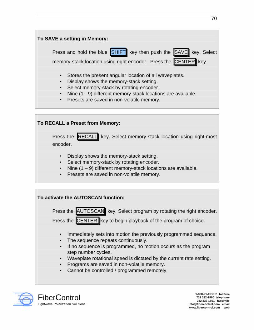
70
FiberControl Lightwave Polarization Solutions
1-888-91-FIBER toll free 732 332-1860 telephone 732 332-1861 facsimile
[email protected] email www.fibercontrol.com web
To SAVE a setting in Memory:
Press and hold the blue SHIFT key then push the SAVE key. Select
memory-stack location using right encoder. Press the CENTER key.
• Stores the present angular location of all waveplates. • Display shows the memory-stack setting. • Select memory-stack by rotating encoder. • Nine (1 - 9) different memory-stack locations are available. • Presets are saved in non-volatile memory.
To RECALL a Preset from Memory:
Press the RECALL key. Select memory-stack location using right-most
encoder.
• Display shows the memory-stack setting. • Select memory-stack by rotating encoder. • Nine (1 – 9) different memory-stack locations are available. • Presets are saved in non-volatile memory.
To activate the AUTOSCAN function:
Press the AUTOSCAN key. Select program by rotating the right encoder.
Press the CENTER key to begin playback of the program of choice.
• Immediately sets into motion the previously programmed sequence. • The sequence repeats continuously. • If no sequence is programmed, no motion occurs as the program
step number cycles. • Waveplate rotational speed is dictated by the current rate setting. • Programs are saved in non-volatile memory. • Cannot be controlled / programmed remotely.

71
FiberControl Lightwave Polarization Solutions
1-888-91-FIBER toll free 732 332-1860 telephone 732 332-1861 facsimile
[email protected] email www.fibercontrol.com web
To program the AUTOSCAN function:
Press and hold the blue SHIFT key then push the PROGRAM key.
Rotate the right encoder to select user program A or user program B.
Press the CENTER key to select a program. Next, program the
waveplates using the front panel controls. Use the ENTER key to
register the each interval. Continue to register intervals, as desired.
• Programmed sequences repeat continuously, therefore, only unique waveplate positions need be set as intervals.
• If no sequence is programmed, no motion occurs. • Each Program has a maximum of 16 intervals, but cannot be
combined into longer interval sequences. • For longer sequences with more independent positions, remote
control can be used. • Waveplate rotational speed is dictated by the current rate setting. • Cannot be controlled / programmed remotely. • Programs are saved in non-volatile memory.
To change the GPIB address:
Press and hold the blue SHIFT key then push the LOCAL key. Rotate
the right encoder to set desired address, and then press the CENTER
key.
• Display indicates the address as the right encoder is rotated. • Address range is 1 to 30 (do not choose 7). • Programs are saved in non-volatile memory. • Default address: MPC1-01, MPC1-02 is 4,
MPC1-M is 4 (ch. 1, 2), and 5 (ch. 3, 4).