Embed Size (px)
Citation preview

User Manual – Analog Input Module
Copyright © Hitachi Europe GmbH 2015. All rights reserved.
EH-RIO2 Series RIO2-AX4I, -AX8I, -AX4V, -AX8V, -AX4H, -RTD2, -RTD4, RTD8, -TC2, -TC4 Version 1.09

User Manual – Analog Input Module
DOCUMENT CHANGE SUMMARY
REV PAGE REMARKS DATE EDITOR 1.09 All Created 18.06.2015 Winter

User Manual – Analog Input Module
Table of Contents 1. Important Notes ......................................................................................................................................................... 1
1.1. Safety Instruction .................................................................................................................................... 2
1.1.1. Symbols ....................................................................................................................................................... 2
1.1.2. Safety Notes ............................................................................................................................................... 2
1.1.3. Certification ................................................................................................................................................ 2
2. ANALOG INPUT MODULE LIST ......................................................................................................................... 3
3. Specification ............................................................................................................................................................... 4
3.1. The Interface and data .......................................................................................................................... 4
3.1.1. RIO2-AX4I .................................................................................................................................................... 4
3.1.2. RIO2-AX8I .................................................................................................................................................... 5
3.1.3. RIO2-AX4V .................................................................................................................................................. 6
3.1.4. RIO2-AX8V .................................................................................................................................................. 7
3.1.5. RIO2-AX4H .................................................................................................................................................. 8
3.1.6. RIO2-RTD2 .................................................................................................................................................. 9
3.1.7. RIO2-RTD4 ................................................................................................................................................ 11
3.1.8. RIO2-RTD8 ................................................................................................................................................ 12
3.1.9. RIO2-TC2 ................................................................................................................................................... 13
3.1.10. RIO2-TC4 ................................................................................................................................................... 14
3.2. Environment Specification ............................................................................................................... 15
3.3. Specification ............................................................................................................................................ 16
3.3.1. RIO2-AX4I .................................................................................................................................................. 16
3.3.2. RIO2-AX8I .................................................................................................................................................. 16
3.3.3. RIO2-AX4V ................................................................................................................................................ 17
3.3.4. RIO2-AX8V ................................................................................................................................................ 17

User Manual – Analog Input Module
3.3.5. RIO2-AX4H ................................................................................................................................................ 18
3.3.6. RIO2-RTD2 ................................................................................................................................................ 18
3.3.7. RIO2-RTD4 ................................................................................................................................................ 19
3.3.8. RIO2-RTD8 ................................................................................................................................................ 20
3.3.9. RIO2-TC2 ................................................................................................................................................... 21
3.3.10. RIO2-TC4 ................................................................................................................................................... 22
4. Dimensions ................................................................................................................................................................ 23
4.1. RIO2-RTD2, RIO2-TC2, RIO2-AX4I, RIO2-AX4V, RIO2-AX4H, RIO2-AX8I, RIO2-AX8V ...................................................................................................................................................................... 23
4.2. RIO2-RTD4, RIO2-RTD8, RIO2-TC4 .............................................................................................. 24
5. Mapping Data into the image Table ............................................................................................................... 25
5.1. RIO2-RTD2, RIO2-TC2 ......................................................................................................................... 25
5.2. RIO2-AX4I, RIO2-AX4V, RIO2-AX4H, RIO2-RTD4, RIO2-TC4 .......................................... 25
5.3. RIO2-AX8I, RIO2-AX8V, RIO2-RTD8 ............................................................................................. 26
6. Trouble Shooting .................................................................................................................................................... 27
6.1. Normal Module ....................................................................................................................................... 27
6.2. RIO2-RTD4, RIO2-RTD8, RIO2-TC4 .............................................................................................. 27

User Manual – Analog Input Module
1
1. Important Notes Solid state equipment has operational characteristics differing from those of electromechanical equipment.
Safety Guidelines for the Application, Installation and Maintenance of Solid State Controls describes some important differences between solid state equipment and hard-wired electromechanical devices.
Because of this difference, and also because of the wide variety of uses for solid state equipment, all persons responsible for applying this equipment must satisfy themselves that each intended application of this equipment is acceptable.
In no event will Hitachi be responsible or liable for indirect or consequential damages resulting from the use or application of this equipment.
The examples and diagrams in this manual are included solely for illustrative purposes. Because of the many variables and requirements associated with any particular installation, Hitachi cannot assume responsibility or liability for actual use based on the examples and diagrams.
If you don’t follow the directions, it could cause a personal injury, damage to the equipment or
explosion
Do not assemble the products and wire with power applied to the system. Else it may cause an electric arc, which can result into unexpected and potentially dangerous action by field devices. Arching is explosion risk in hazardous locations. Be sure that the area is non-hazardous or remove system power appropriately before assembling or wiring the modules.
Do not touch any terminal blocks or IO modules when system is running. Else it may cause the unit to an electric shock or malfunction.
Keep away from the strange metallic materials not related to the unit and wiring works should be controlled by the electric expert engineer. Else it may cause the unit to a fire, electric shock or malfunction.
If you disobey the instructions, there may be possibility of personal injury, damage to equipment
or explosion. Please follow below Instructions.
Check the rated voltage and terminal array before wiring. Avoid the circumstances over 55℃ of temperature. Avoid placing it directly in the sunlight.
Avoid the place under circumstances over 85% of humidity.
Do not place Modules near by the inflammable material. Else it may cause a fire.
Do not permit any vibration approaching it directly.
Go through module specification carefully, ensure inputs, output connections are made with the specifications. Use standard cables for wiring.
Use Product under pollution degree 2 environment.
Warning!
Caution!

User Manual – Analog Input Module
2
1.1. Safety Instruction 1.1.1. Symbols
1.1.2. Safety Notes
The modules are equipped with electronic components that may be
destroyed by electrostatic discharge. When handling the modules, ensure
that the environment (persons, workplace and packing) is well grounded.
Avoid touching conductive components, e.g. FnBUS Pin.
1.1.3. Certification
CE Certificate
EN 61000-6-2; Industrial Immunity
EN 61000-6-4; Industrial Emissions
RoHS (EU, CHINA)
Identifies information about practices or circumstances that can cause an
explosion in a hazardous environment, which may lead to personal injury or
death property damage, or economic loss
Identifies information that is critical for successful application and understanding of the product
Identifies information about practices or circumstances that can lead to personal
Injury, property damage, or economic loss.
Attentions help you to identity a hazard, avoid a hazard, and recognize the
consequences

User Manual – Analog Input Module
3
2. ANALOG INPUT MODULE LIST
Number Description Production Status
RIO2-AX4I 4 Channels, Current, 4~20mA, 12bit Active RIO2-AX8I 8 Channels, Current, 4~20mA, 12bit Active RIO2-AX4V 4 Channels, Voltage, 0~10Vdc, 12bit Active RIO2-AX8V 8 Channels, Voltage, 0~10Vdc, 12bit Active RIO2-AX4H 4 Channels, Voltage, -10Vdc~10Vdc, 12bit Active RIO2-RTD2 2 Channels, RTD, Status Active RIO2-RTD4 4 Channels, RTD, Status Active RIO2-RTD8 8 Channels, RTD, Status Active RIO2-TC2 2 Channels, TC Active RIO2-TC4 4 Channels, TC Active

User Manual – Analog Input Module
4
3. Specification 3.1. The Interface and data 3.1.1. RIO2-AX4I
Pin No. Description Pin No. Description
0 Input Channel 0 1 Input Channel 1 2 Input Channel 2 3 Input Channel 3 4 Input Channel Common (0V) 5 Input Channel Common (0V) 6 Chassis Ground / Shield 7 Chassis Ground / Shield
Current 3.0mA 4.0mA 5.0mA 10.0mA 20.0mA Data(Hex) H 8000 H 0000 H 00FF H 05FF H 0FFF
User Manual – Analog Input Module
5
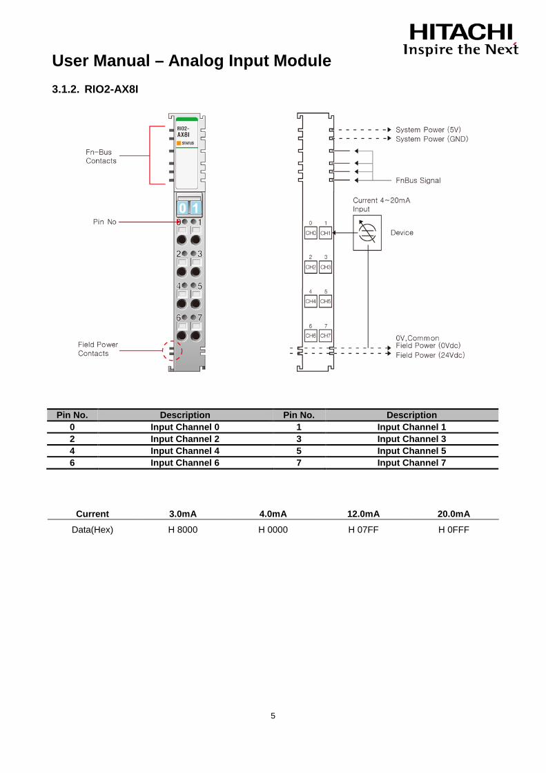
3.1.2. RIO2-AX8I
Pin No. Description Pin No. Description
0 Input Channel 0 1 Input Channel 1 2 Input Channel 2 3 Input Channel 3 4 Input Channel 4 5 Input Channel 5 6 Input Channel 6 7 Input Channel 7
Current 3.0mA 4.0mA 12.0mA 20.0mA Data(Hex) H 8000 H 0000 H 07FF H 0FFF

User Manual – Analog Input Module
6
3.1.3. RIO2-AX4V
Pin No. Description Pin No. Description
0 Input Channel 0 1 Input Channel 1 2 Input Channel 2 3 Input Channel 3 4 Input Channel Common (0V) 5 Input Channel Common (0V) 6 Chassis Ground / Shield 7 Chassis Ground / Shield
Voltage 0V 2.5V 5V 10V
Data(Hex) H 0000 H 03FF H 07FF H 0FFF

User Manual – Analog Input Module
7
3.1.4. RIO2-AX8V
Pin No. Description Pin No. Description
0 Input Channel 0 1 Input Channel 1 2 Input Channel 2 3 Input Channel 3 4 Input Channel 4 5 Input Channel 5 6 Input Channel 6 7 Input Channel 7
Voltage 0V 2.5V 5V 10V
Data(Hex) H 0000 H 03FF H 07FF H 0FFF

User Manual – Analog Input Module
8
3.1.5. RIO2-AX4H
Pin No. Description Pin No. Description
0 Input Channel 0 1 Input Channel 1 2 Input Channel 2 3 Input Channel 3 4 Input Channel Common (0V) 5 Input Channel Common (0V) 6 Chassis Ground / Shield 7 Chassis Ground / Shield
Voltage -10V -5V 0V 5V 10V
Data(Hex) H F800 H FC00 H 0000 H 03FF H 07FF

User Manual – Analog Input Module
9
3.1.6. RIO2-RTD2
Pin No. Description Pin No. Description
0 Input Channel 0_A 1 Input Channel 1_A 2 Input Channel 0_B 3 Input Channel 1_B 4 Analog Ground 5 Analog Ground 6 Shield 7 Shield

User Manual – Analog Input Module
10
Resistance 100mΩ
0Ω 500Ω 1000Ω 1500Ω 2000Ω
Data(Hex) H 0000 H 1388 H 2710 H 3A98 H 4E20
Sensor PT100
-200℃ -100℃ 0℃ 200℃ 400℃ 600℃ 850℃
Data(Hex) H F830 H FC18 H 0000 H 07D0 H 0FA0 H 1770 H 2134
Sensor JPT100 -200℃ -100℃ 0℃ 200℃ 400℃ 640℃
Data(Hex) H F830 H FC18 H 0000 H 07D0 H 0FA0 H 1900
Sensor Type Data Sensor Type Degree Counts Resolution
Resistance 100mΩ Resistance 10mΩ Resistance 20mΩ
1~2000Ω
1~327Ω
1~620Ω
10~20000
10~3270
10~6200
100mΩ / 1count
10mΩ / 1count
20mΩ / 1count
PT50, 0.00385
PT100, 0.00385
PT200, 0.00385
PT500, 0.00385
PT1000, 0.00385
200~850℃
-200~850℃
-200~850℃
-200~850℃
-200~350℃
-2000~8500
-2000~8500
-2000~8500
-2000~8500
-2000~3500
0.1℃ or 0.1℉ / count
0.1℃ or 0.1℉ / count
0.1℃ or 0.1℉ / count
0.1℃ or 0.1℉ / count
0.1℃ or 0.1℉ / count
JPT100, 0.003916
JPT200, 0.003916
JPT500, 0.003916
JPT1000, 0.003916
-200~640℃
-200~640℃
-200~640℃
-200~350℃
-2000~6400
-2000~6400
-2000~6400
-2000~3500
0.1℃ or 0.1℉ / count
0.1℃ or 0.1℉ / count
0.1℃ or 0.1℉ / count
0.1℃ or 0.1℉ / count
NI100, 0.00618
NI120, 0.00672
NI200, 0.00618
NI500, 0.00618
NI1000, 0.00618
-60~250℃
-80~250℃
-60~250℃
-60~250℃
-60~180℃
-600~2500
-800~2500
-600~2500
-600~2500
-600~1800
0.1℃ or 0.1℉ / count
0.1℃ or 0.1℉ / count
0.1℃ or 0.1℉ / count
0.1℃ or 0.1℉ / count
0.1℃ or 0.1℉ / count
CU10, 0.00427 -200~260℃ -2000~2600 0.1℃ or 0.1℉ / count

User Manual – Analog Input Module
11
3.1.7. RIO2-RTD4
Pin No. Description Pin No. Description
1 RTD Ch#0+ 2 RTD Ch#0- 3 RTD Ch#1+ 4 RTD Ch#1- 5 RTD Ch#2+ 6 RTD Ch#2- 7 RTD Ch#3+ 8 RTD Ch#3- 9 AGND 10 AGND 11 - 12 - 13 - 14 - 15 - 16 - 17 - 18 - 19 AGND 20 AGND
PT100
Sensor PT100
-200℃ -100℃ 0℃ 200℃ 400℃ 600℃ 850℃
Data(Hex) H F830 H FC18 H 0000 H 07D0 H 0FA0 H 1770 H 2134

User Manual – Analog Input Module
12
3.1.8. RIO2-RTD8
Pin No. Description Pin No. Description
1 RTD Ch#0+ 2 RTD Ch#0- 3 RTD Ch#1+ 4 RTD Ch#1- 5 RTD Ch#2+ 6 RTD Ch#2- 7 RTD Ch#3+ 8 RTD Ch#3- 9 AGND 10 AGND 11 RTD Ch#4+ 2 RTD Ch#4- 13 RTD Ch#5+ 4 RTD Ch#5- 15 RTD Ch#6+ 6 RTD Ch#6- 17 RTD Ch#7+ 8 RTD Ch#7- 19 AGND 20 AGND
PT100
Sensor PT100
-200℃ -100℃ 0℃ 200℃ 400℃ 600℃ 850℃
Data(Hex) H F830 H FC18 H 0000 H 07D0 H 0FA0 H 1770 H 2134

User Manual – Analog Input Module
13
3.1.9. RIO2-TC2
Pin No. Description Pin No. Description
0 Input Channel 0+ 1 Input Channel 1+ 2 Input Channel 0- 3 Input Channel 1- 4 Analog Ground 5 Analog Ground 6 Shield 7 Shield
Type B
temperature℃ 0℃ 300℃ 900℃ 1800℃ Data(Hex) H 0000 H 0BB8 H 2328 H 4650
Thermocouple Input Range
Type Maximum Input Range Recommended Input Range Type K -270 ~ 1372 ℃ -100 ~ 1200 ℃ Type J -210 ~ 1200 ℃ -100 ~ 1100 ℃ Type T -270 ~ 400 ℃ -200 ~ 350 ℃ Type B 30 ~ 1820 ℃ 500 ~ 1700 ℃ Type R -50 ~ 1768 ℃ 0 ~ 1600 ℃ Type S -50 ~ 1768 ℃ 0 ~ 1600 ℃ Type E -270 ~ 1000 ℃ -200 ~ 800 ℃ Type N -270 ~1300 ℃ -200 ~ 1250 ℃ Type L -200 ~ 900 ℃ -100 ~ 850 ℃ Type U -200 ~ 600 ℃ -100 ~ 550 ℃ Type C 0 ~ 2310 ℃ 100 ~ 2100 ℃ Type D 0 ~ 2490 ℃ 100 ~ 2200 ℃
- ℉ = 1.8℃+32

User Manual – Analog Input Module
14
3.1.10. RIO2-TC4
Pin No. Description Pin No. Description
1 TC Ch#0+ 2 TC Ch#0- 3 TC Ch#1+ 4 TC Ch#1- 5 TC Ch#2+ 6 TC Ch#2- 7 TC Ch#3+ 8 TC Ch#3- 9 AGND 10 AGND 11 - 2 - 13 - 4 - 15 - 6 - 17 - 8 - 19 External PT100 20 External PT100
Type B temperature℃ 0℃ 300℃ 900℃ 1800℃
Data(Hex) H 0000 H 0BB8 H 2328 H 4650
LED : External PT100 Sensor status for Cold Junction Compensation (E) Status LED is To indicate
Normal Operation Off External PT100 Sensor Not Found
Normal Operation Green External PT100 Sensor Found

User Manual – Analog Input Module
15
3.2. Environment Specification Environmental Specifications Operating Temperature Non-Operating Temperature Relative Humidity Operating Altitude Mounting
-20 to 55℃ (Discrete I/O) 0 to 55℃ (Analog I/O) -40℃ to 85℃ 5%~90% non-condensing 2000m DIN rail
General Specifications Shock Operating 10g Shock Non-Operating 30g Vibration/Shock resistance Displacement : 0.012Inch p-p from 10~57Hz
Acceleration : 2G’s from 57~500Hz Sweep Rate : 1 octave Per Minute Axes to test : x, y, z Frequency Sweeps Per Axis : 10
EMC resistance burst/ESD Conforms to EN-61000-6-2 EMI Conforms to EN-61000-6-4 Installation Pos. /Protect. Class Variable / IP20 Product Certification CE Network Conformance RIO2-PBA : PTO Conformance Test Completion Isolation DC Module (Included Analog Module) : Terminal Block to F.G
500Vac/1min AC Module : Terminal Block to F.G 1500Vac/1min Relay Module : Terminal Block to F.G 2500Vac/1min

User Manual – Analog Input Module
16
3.3. Specification 3.3.1. RIO2-AX4I Items Specification Input Specification Number of Inputs 4 Channels Single Ended, Non-isolated Between Channels Indicators 4 Green/Red States, 1 Green/Red FnBus State Resolution in Ranges 12Bits : 3.9uA/Bit Input current Range 4 ~ 20mA Data Format 16bits Integer (2's compliment) Module Error ±0.1% Full Scale @25℃
±0.3% Full Scale @0℃, 60℃ Input Impedance 120Ω Conversion Time 4msec / All channel Calibration Not Required Diagnostic Channel Open ( if < 3mA, Data=0x8000 ) Common Type 4 Channels / 2COM (Single Common) General Specification Power Supply From System Power DC/DC Power Dissipation Max. 165mA @ 5.0Vdc Isolation I/O to Logic : Photocoupler isolation
Field power : Not Connected Wiring I/O Cable Max. 2.0㎟ Weight 70g Module Size 12mm x 99mm x 70mm Environment Condition Refer to " Environment Specification"(page : 15) 3.3.2. RIO2-AX8I Items Specification Input Specification Number of Inputs 8 Channels Single Ended Indicators 1 Green/Red FnBus State Resolution in Ranges 12Bits : 3.9uA/Bit Input current Range 4 ~ 20mA Data Format 16bits Integer (2's compliment) Module Error ±0.1% Full Scale @25℃
±0.3% Full Scale @0℃, 60℃ Input Impedance 120Ω Conversion Time 4msec / All channel Calibration Not Required Diagnostic No Common Type Nothing in the module terminal
Field Power 0V is Common(AGND) General Specification Power Dissipation Max. 80mA @ 5.0Vdc Isolation I/O to Logic : Photocoupler isolation
I/O to Logic : Non-Isolation Field Power Supply Voltage : 24Vdc nominal
Voltage Range : 18~28.8Vdc Power Dissipation: Max. 40mA@24Vdc
Wiring I/O Cable Max. 2.0㎟ Weight 70g Module Size 12mm x 99mm x 70mm Environment Condition Refer to " Environment Specification"(page : 15)

User Manual – Analog Input Module
17
3.3.3. RIO2-AX4V Items Specification Input Specification Number of Inputs 4 Channels Single Ended, Non-isolated Between Channels Indicators 4 Green/Red States, 1 Green/Red FnBus State Resolution in Ranges 12Bits : 2.44mV/Bit Input current Range 0~10Vdc Data Format 16bits Integer (2's compliment) Module Error ±0.1% Full Scale @25℃
±0.3% Full Scale @0℃, 60℃ Input Impedance 500KΩ Conversion Time 4msec / All channel Calibration Not Required Diagnostic No Common Type 4 Channels / 2COM (Single Common) General Specification Power Supply From System Power DC/DC Power Dissipation Max. 165mA @ 5.0Vdc Isolation I/O to Logic : Photocoupler isolation
Field power : Not Connected Wiring I/O Cable Max. 2.0㎟ Weight 70g Module Size 12mm x 99mm x 70mm Environment Condition Refer to " Environment Specification"(page : 15) 3.3.4. RIO2-AX8V Items Specification Input Specification Number of Inputs 8 Channels Single Ended Indicators 1 Green/Red FnBus State Resolution in Ranges 12Bits : 2.44mV/Bit Input current Range 0~10Vdc Data Format 16bits Integer (2's compliment) Module Error ±0.1% Full Scale @25℃
±0.3% Full Scale @0℃, 60℃ Input Impedance 500KΩ Conversion Time 4msec / All channel Calibration Not Required Diagnostic No Common Type Nothing in the module terminal
Field Power 0V is Common(AGND) General Specification Power Dissipation Max. 80mA @ 5.0Vdc Isolation I/O to Logic : Photocoupler isolation
Field power : Non-Isolation Field Power Supply Voltage : 24Vdc nominal
Voltage Range : 18~28.8Vdc Power Dissipation: Max. 40mA@24Vdc
Wiring I/O Cable Max. 2.0㎟ Weight 70g Module Size 12mm x 99mm x 70mm Environment Condition Refer to " Environment Specification"(page : 15)
User Manual – Analog Input Module
18
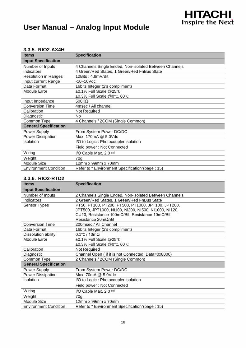
3.3.5. RIO2-AX4H Items Specification Input Specification Number of Inputs 4 Channels Single Ended, Non-isolated Between Channels Indicators 4 Green/Red States, 1 Green/Red FnBus State Resolution in Ranges 12Bits : 4.8mV/Bit Input current Range -10~10Vdc Data Format 16bits Integer (2's compliment) Module Error ±0.1% Full Scale @25℃
±0.3% Full Scale @0℃, 60℃ Input Impedance 500KΩ Conversion Time 4msec / All channel Calibration Not Required Diagnostic No Common Type 4 Channels / 2COM (Single Common) General Specification Power Supply From System Power DC/DC Power Dissipation Max. 170mA @ 5.0Vdc Isolation I/O to Logic : Photocoupler isolation
Field power : Not Connected Wiring I/O Cable Max. 2.0㎟ Weight 70g Module Size 12mm x 99mm x 70mm Environment Condition Refer to " Environment Specification"(page : 15) 3.3.6. RIO2-RTD2 Items Specification Input Specification Number of Inputs 2 Channels Single Ended, Non-isolated Between Channels Indicators 2 Green/Red States, 1 Green/Red FnBus State Sensor Types PT50, PT100, PT200, PT500, PT1000, JPT100, JPT200,
JPT500, JPT1000, NI100, Nl200, NI500, NI1000, NI120, CU10, Resistance 100mΩ/Bit, Resistance 10mΩ/Bit, Resistance 20mΩ/Bit
Conversion Time 200msec / All Channel Data Format 16bits Integer (2's compliment) Dissolution ability 0.1℃ / 10mΩ Module Error ±0.1% Full Scale @25℃
±0.3% Full Scale @0℃, 60℃ Calibration Not Required Diagnostic Channel Open ( if it is not Connected, Data=0x8000) Common Type 2 Channels / 2COM (Single Common) General Specification Power Supply From System Power DC/DC Power Dissipation Max. 70mA @ 5.0Vdc Isolation I/O to Logic : Photocoupler isolation
Field power : Not Connected Wiring I/O Cable Max. 2.0㎟ Weight 70g Module Size 12mm x 99mm x 70mm Environment Condition Refer to " Environment Specification"(page : 15)

User Manual – Analog Input Module
19
3.3.7. RIO2-RTD4 Items Specification Input Specification Number of Inputs 4 Channels Indicators 1 Green/Red Status, 4 Green States Sensor Types RTD Input
- PT 100, PT200, PT500, PT1000, PT50 - JPT100, JPT200, JPT500, JPT1000, JPT50 - NI100, NI200, NI500, NI000 - NI120, NI1000LG Resistance Input - 100mΩ/bit, 10mΩ/bit, 20mΩ/bit, 50mΩ/bit
Excitation Current About 1mA Conversion Method 3-Wire or 2-Wire Conversion Time 30msec/1Channel when Normal Conversion Data Format 16bits singed Integer(2's compliment) Resolution of Data ±0.1℃/ F, 10mΩ Module Accuracy ±0.1% Full Scale @25℃
±0.3% Full Scale @0℃, 60℃ Calibration Not Required Diagnostic Sensor Open or Range Over,
then Conversion Data=0x8000(-32768) Except Resistance Input Mode
Common Type 4 Common/Module General Specification Power Dissipation Max. 100mA @5.0Vdc Isolation I/O to Control Logic : Photocoupler Isolation Field power Not used, Field Power by pass to next expansion module Wiring Connector Type, up to AWG22
Module Connector : HIF3BA-20D-2.54DSA Weight 70g Module Size 12mm x 99mm x 70mm Environment Condition Refer to " Environment Specification"(page : 15)

User Manual – Analog Input Module
20
3.3.8. RIO2-RTD8 Items Specification Input Specification Number of Inputs 8 Channels Indicators 1 Green/Red LED, Module Status, 8Green LED, Input State Sensor Types RTD Input
- PT 100, PT200, PT500, PT1000, PT50 - JPT100, JPT200, JPT500, JPT1000, JPT50 - NI100, NI200, NI500, NI000 - NI120, NI1000LG Resistance Input - 100mΩ/bit, 10mΩ/bit, 20mΩ/bit, 50mΩ/bit
Excitation Current About 1mA Conversion Method 3-Wire or 2-Wire Conversion Time 30msec/1Channel when Normal Conversion Data Format 16bits singed Integer(2's compliment) Resolution of Data ±0.1℃/ F, 10mΩ Module Accuracy ±0.1% Full Scale @25℃
±0.3% Full Scale @0℃, 60℃ Calibration Not Required Diagnostic Sensor Open or Range Over,
then Conversion Data=0x8000(-32768) Except Resistance Input Mode
Common Type 4 Common/Module General Specification Power Dissipation Max. 110mA @5.0Vdc Isolation I/O to Control Logic : Photocoupler Isolation Field power Not used, Field Power by pass to next expansion module Wiring Connector Type, up to AWG22
Module Connector : HIF3BA-20D-2.54DSA Weight 70g Module Size 12mm x 99mm x 70mm Environment Condition Refer to " Environment Specification"(page : 15)

User Manual – Analog Input Module
21
3.3.9. RIO2-TC2 Items Specification Input Specification Number of Inputs 2 Channels Single Ended, Non-isolated Between Channels Indicators 2 Green/Red States, 1 Green/Red FnBus State Sensor Types Type K/J/T/B/R/S/E/N/L/U/C/D
mV Input10uV/Bit, 1uV/Bit, 2uV/Bit Conversion Time 200msec / All Channel Data Format 16bits Integer (2's compliment) Dissolution ability 0.1℃ / 10mΩ Module Error ±0.1% Full Scale @25℃
±0.3% Full Scale @0℃, 60℃ Calibration Not Required Diagnostic Channel Open ( if it is not Connected, Data=0x8000) Common Type 2 Channels / 2COM (Single Common) General Specification Power Supply From System Power DC/DC Power Dissipation Max. 70mA @ 5.0Vdc Isolation I/O to Logic : Photocoupler isolation
Field power : Not Connected Connection 2 or 3-Wire Wiring I/O Cable Max. 2.0㎟ Weight 70g Module Size 12mm x 99mm x 70mm Environment Condition Refer to " Environment Specification"(page : 15)

User Manual – Analog Input Module
22
3.3.10. RIO2-TC4 Items Specification Input Specification Number of Inputs 4 Channels Indicators 1 Green/Red LED, Module Status
4 Green LED, Input State 1 Green LED, E, Cold Junction
Sensor Types Thermocouple Input - Type K/J/T/B/R/S/E/N/L/U/C/D mV Input -10uV/bit, 1uV/bit, 2uV/bit
Cold Junction Temperature
-20~70℃
Cold Junction Compensation Method
External “PT100 Sensor (recommended) or Internal Temperature Sensor *Auto Detection if External PT100 (high priority) is Connected
Conversion Time 30msec/1Channel when Normal Conversion Data Format 16bits Integer (2's compliment) Resolution of Data ±0.1℃/ F, 10mΩ Module Accuracy ±0.1% Full Scale @25℃ (K/J/mV)
±0.3% Full Scale @0℃, 60℃(K/J/mV) ±0.5% Full Scale @25℃ (The others) ±1.0% Full Scale @0℃, 60℃(The others)
Calibration Not Required Diagnostic Sensor Open or Range Over,
then Conversion Data=0x8000(-32768) Common Type 1 Common / 1 Input General Specification System Power Dissipation
Max. 120mA @ 5.0Vdc
Isolation I/O to Control Logic : Photocoupler Isolation Field Power Not used, Field Power by pass to next expansion module Wiring Connector Type, up to AWG22
Module Connector : HIF3BA-20D-2.54DSA Weight 70g Module Size 12mm x 99mm x 70mm Environment Condition Refer to " Environment Specification"(page : 15)
- For more Accuracy, strongly recommend to use Extern PT100 Sensor for Cold Junction Compensation.
- If External PT100 Sensor is found, RIO2-TC4/3808 uses PT100 Temperature as Cold Junction Compensation.

User Manual – Analog Input Module
23
4. Dimensions 4.1. RIO2-RTD2, RIO2-TC2, RIO2-AX4I, RIO2-AX4V, RIO2-AX4H, RIO2-AX8I,
RIO2-AX8V (mm)
User Manual – Analog Input Module
24
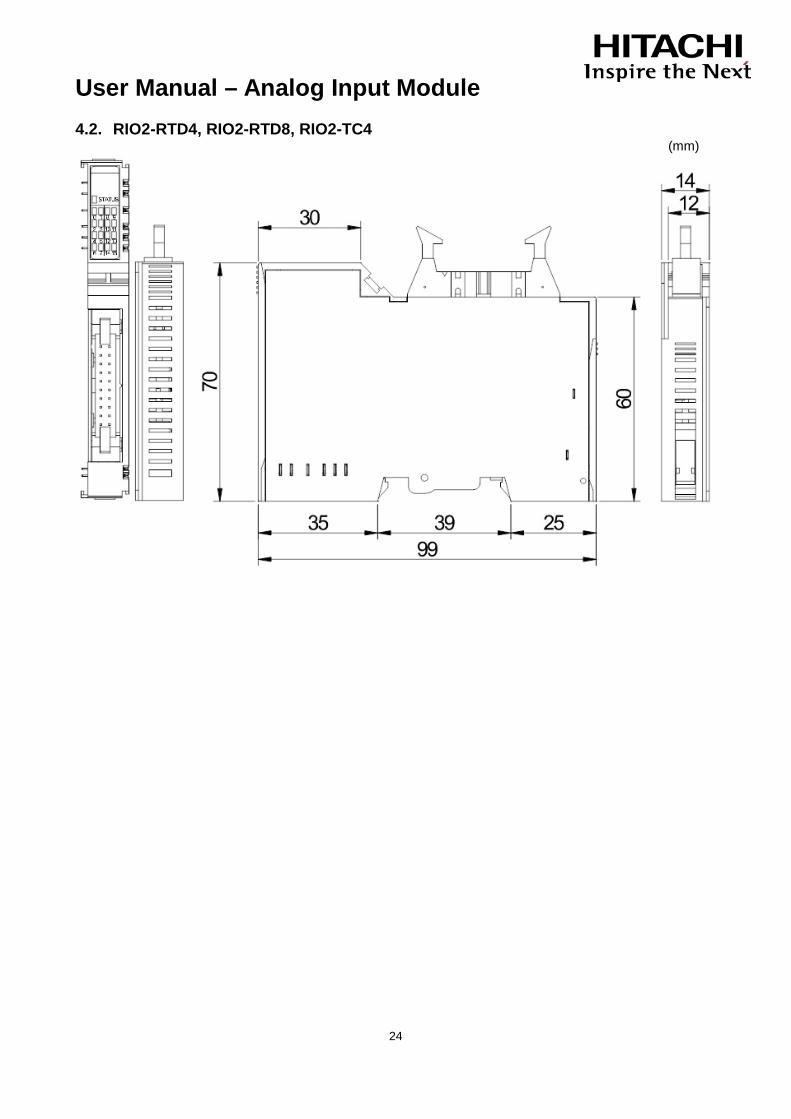
4.2. RIO2-RTD4, RIO2-RTD8, RIO2-TC4 (mm)
User Manual – Analog Input Module
25
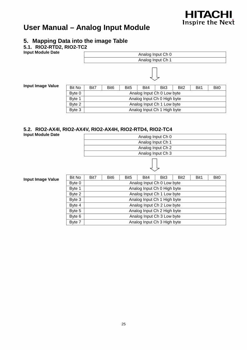
5. Mapping Data into the image Table 5.1. RIO2-RTD2, RIO2-TC2 Input Module Date Input Image Value 5.2. RIO2-AX4I, RIO2-AX4V, RIO2-AX4H, RIO2-RTD4, RIO2-TC4 Input Module Date
Input Image Value
Analog Input Ch 0 Analog Input Ch 1
Bit No Bit7 Bit6 Bit5 Bit4 Bit3 Bit2 Bit1 Bit0 Byte 0 Analog Input Ch 0 Low byte Byte 1 Analog Input Ch 0 High byte Byte 2 Analog Input Ch 1 Low byte Byte 3 Analog Input Ch 1 High byte
Analog Input Ch 0 Analog Input Ch 1 Analog Input Ch 2 Analog Input Ch 3
Bit No Bit7 Bit6 Bit5 Bit4 Bit3 Bit2 Bit1 Bit0 Byte 0 Analog Input Ch 0 Low byte Byte 1 Analog Input Ch 0 High byte Byte 2 Analog Input Ch 1 Low byte Byte 3 Analog Input Ch 1 High byte Byte 4 Analog Input Ch 2 Low byte Byte 5 Analog Input Ch 2 High byte Byte 6 Analog Input Ch 3 Low byte Byte 7 Analog Input Ch 3 High byte
User Manual – Analog Input Module
26
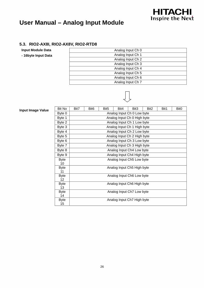
5.3. RIO2-AX8I, RIO2-AX8V, RIO2-RTD8 Input Module Data - 16byte Input Data
Input Image Value
Analog Input Ch 0 Analog Input Ch 1 Analog Input Ch 2 Analog Input Ch 3 Analog Input Ch 4 Analog Input Ch 5 Analog Input Ch 6 Analog Input Ch 7
Bit No Bit7 Bit6 Bit5 Bit4 Bit3 Bit2 Bit1 Bit0 Byte 0 Analog Input Ch 0 Low byte Byte 1 Analog Input Ch 0 High byte Byte 2 Analog Input Ch 1 Low byte Byte 3 Analog Input Ch 1 High byte Byte 4 Analog Input Ch 2 Low byte Byte 5 Analog Input Ch 2 High byte Byte 6 Analog Input Ch 3 Low byte Byte 7 Analog Input Ch 3 High byte Byte 8 Analog Input Ch4 Low byte Byte 9 Analog Input Ch4 High byte Byte 10
Analog Input Ch5 Low byte
Byte 11
Analog Input Ch5 High byte
Byte 12
Analog Input Ch6 Low byte
Byte 13
Analog Input Ch6 High byte
Byte 14
Analog Input Ch7 Low byte
Byte 15
Analog Input Ch7 High byte

User Manual – Analog Input Module
27
6. Trouble Shooting
In this manual, it couldn’t be described all variety case with Network Adapter of several protocols. So if you couldn’t find any fault after investigating all below cases, refer to NA user manual.
6.1. Normal Module
LED Status Cause Action
EXPANSION MODULE STATUS LED Off
Green
Flashing Green
Flashing Red
Red
Not Power No Initialized
Device has no expansion Module or may not be powered
The Parameter is not initialized yet.
Fn-Bus Connection FnBus normal Operation
Fn-Bus Ready FnBus ready
Fn-Bus Fault FnBus Time Out,
FnBus Failed Communication
Device Fault Device fault
CHANNEL STATUS LED
Off Not Signal Normal Operation
Green On Signal Normal Operation
6.2. RIO2-RTD4, RIO2-RTD8, RIO2-TC4
LED Status Cause Action
EXPANSION MODULE STATUS LED
Off
Green
Flashing Green
Flashing Red
Red
Not Power No Initialized
Not powered Not Initialized yet.
Module Connection Normal Operation, IO Exchange
Module Ready Module ready
Module Fault Module failed in Communication
Module Fault Module fault
User Manual – Analog Input Module
28
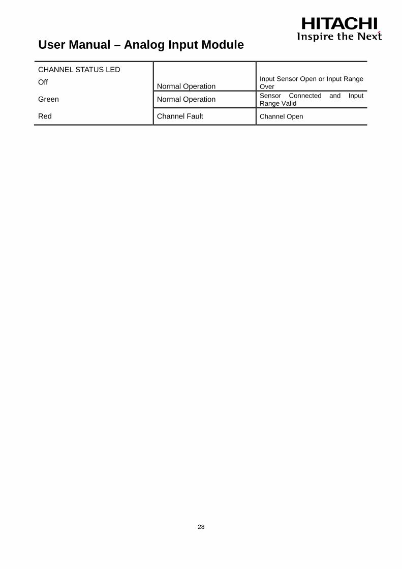
CHANNEL STATUS LED
Off Normal Operation Input Sensor Open or Input Range Over
Green Normal Operation Sensor Connected and Input Range Valid
Red Channel Fault Channel Open

Hitachi Europe GmbH Am Seestern 18 Tel: +49 (0) 211 52 83-0 D-40547 Düsseldorf, Germany Fax: +49 (0) 211 52 83-649