Embed Size (px)
Citation preview
Revision 3.04
EXPERTS IN WATER CHEMISTRY SINCE 1903
3051 Hardness Analyzer User Manual

Waltron Customer Commitment
1 Waltron User Manual 3051 Hardness Analyzer
WALTRON CUSTOMER COMMITMENT
This instruction manual is a technical guide to aid the customer in the set-up, operation, and
maintenance of their new Waltron measuring system. Waltron provides continuous product
improvement and reserves the right to make any modifications to the information contained
herein without notice.
Copyright © Waltron Bull & Roberts, LLC, 2016
All Rights Reserved
Technical questions concerning this product should be addressed to:
Waltron Technical Service Department
Flemington, New Jersey
Phone: (908)-534-5100
Fax: (908)-534-5546
www.waltron.net
Please be ready to provide the following information:
Date analyzer was purchased
Analyzer model and serial number
Recent maintenance history
Calibration slope values and detailed description of problem
Waltron’s technical expertise and extensive experience provides personalized solutions to the
water quality industry. It is Waltron’s commitment to provide the customer with timely and
accurate technical service and support.
Waltron fully expects the customer to be satisfied with the quality, performance, and cost of this
product.
If there are any questions or concerns regarding this product, please feel free to contact Waltron
at (908)-534-5100.
Thank you for choosing Waltron!
Please note the Waltron mailing and shipping address:
Waltron Bull & Roberts, LLC
25 Minneakoning Road, Suite 101
Flemington, NJ 08822
Safety
2 Waltron User Manual 3051 Hardness Analyzer
SAFETY
Please observe proper safety and handling precautions when installing, operating, maintaining,
and servicing this product. The following should be noted and adhered to:
Read and understand manual before working with analyzer.
Pay special attention to warning labels on enclosures, containers, packages and
chemicals.
Only qualified personnel should be involved in the installation, operation, and servicing
of the analyzer.
Follow safety precautions when operating analyzer in conditions of high pressure and/or
temperature.
Keep analyzer chemicals away from heat and extreme temperatures. Reagent powders
must be kept dry.
Follow all regulations and warning labels when disposing of chemicals. Do not mix
chemicals.
To obtain analyzer safety information or Safety Data Sheets (SDS), please contact Waltron or
visit the website at www.waltron.net .
Warranty Agreement
3 Waltron User Manual 3051 Hardness Analyzer
WARRANTY AGREEMENT
If, within one year from the date of shipment, the customer experiences any equipment defects or
is not satisfied with the analyzer manufacturing, Waltron will repair, or at its option, replace any
defective part(s) free of charge. This warranty requires that the defective part(s) be returned to
Waltron with shipping charges prepaid.
At Waltron discretion, a Technical Service Specialist may be sent out to repair or replace the
defective part(s) on location. Traveling time and expenses of the Technical Service Specialist is
at the customer’s expense.
Equipment sent to Waltron must be appropriately packaged and the following information must
be provided prior to returning to Waltron:
The Return Authorization (RA) number assigned to the customer by the Waltron
Technical Service Department
Customer name, address and department
Name and telephone number of the individual responsible for returning items for repair
Brief problem description
Ship to Waltron service center:
Waltron Bull & Roberts, LLC
25 Minneakoning Road, Suite 101
Flemington, NJ 08822
The Waltron Warranty Agreement:
Covers expendable sensors for one month after shipment and reusable electrodes for six
months after shipment.
Does not apply to damages occurred during shipping.
Warranty will be nullified if goods have been used for purposes other than those for
which they are intended or if any seal has been removed, broken or tampered with or if
the Waltron trademark or serial number has be removed, defaced, or altered.
Does not cover expendable supply items such as reagents, tubing and electrolytes.
Does not cover misuse or mistreatment by the user.
Does not cover previous repair or alteration by unauthorized individuals.
Waltron does not assume responsibility for contingent liability through alleged failure or failures
of products or product accessories.
Checklist of Materials
4 Waltron User Manual 3051 Hardness Analyzer
CHECKLIST OF MATERIALS
In order to ensure customer satisfaction, Waltron does its best to provide adequate and
timely packaging and shipping services. Please perform the following after receiving a
shipment:
Inspect all shipping containers upon receipt and record any visible damage. If there are
any outward signs of damage, please retain all containers and packages for inspection by
carrier. Please retain all packing material so that it can be used for future moving and
shipping needs.
Check all items received against those on the packing list. Chemicals are usually shipped
in a separate package and will be itemized accordingly.
Verify that the number of packages received agrees with the packing list and shipping
papers.
Notify both Waltron and the carrier if any problems occur.
Important Notice:
All analyzers are inspected and tested prior to shipment.
In normal use, the unit should require only minor maintenance and should operate
correctly and without fault over a long period of time.
Please note that if electronic components need to be replaced, it may be necessary to
adjust and/or calibrate the analyzer.
Failure to carry out correct maintenance procedures may result in inaccurate analyzer
readings.
Table of Contents
5 Waltron User Manual 3051 Hardness Analyzer
TABLE OF CONTENTS
Waltron Customer Commitment .............................................................. 1
Safety ......................................................................................................... 2
Warranty Agreement ................................................................................. 3
Checklist of Materials ............................................................................... 4
Table of Contents ..................................................................................... 5
List of Figures ........................................................................................... 7
List of Tables ............................................................................................. 8
1 Overview .............................................................................................. 9
1.1 Specifications ............................................................................................................... 9 1.1.1 Performance ......................................................................................................... 9 1.1.2 Sample Operating Conditions ............................................................................... 9 1.1.3 Signal Outputs .....................................................................................................10 1.1.4 Operational Calibration ........................................................................................10
1.2 Safety Precautions, Instructions, and Hazards ............................................................10 1.2.1 General Information .............................................................................................10 1.2.2 List of Warnings and Potential Dangers ...............................................................10 1.2.3 Reagents .............................................................................................................12 1.2.4 Sample ................................................................................................................12 1.2.5 Waste Disposal ....................................................................................................12 1.2.6 Analyzer General Hazards ...................................................................................12
2 Introduction ....................................................................................... 15
2.1 Analyzer Description ...................................................................................................15 2.2 Applications ................................................................................................................16 2.3 Working Principle ........................................................................................................16 2.4 Analysis Cycle ............................................................................................................18
2.4.1 Programming Commands ....................................................................................18 2.4.2 Flow Diagram .......................................................................................................19 2.4.3 Analyzer Operations ............................................................................................19
2.5 Fast Loop Reservoir ....................................................................................................20 2.6 Wet-Section Box .........................................................................................................22 2.7 Electronics ..................................................................................................................23
3 Installation ......................................................................................... 24
3.1 Receiving ....................................................................................................................24 3.2 Analyzer Handling .......................................................................................................24 3.3 Location and Mounting ................................................................................................24 3.4 Pre-Installation ............................................................................................................24 3.5 Mouting Schematics ....................................................................................................25 3.6 Electrical Connections ................................................................................................26
3.6.1 AC Power Connection ..........................................................................................26
Table of Contents
6 Waltron User Manual 3051 Hardness Analyzer
3.6.2 User Signal Connections .....................................................................................27
3.7 Reagent Information ...................................................................................................28 3.8 Reagents Holding Bracket ..........................................................................................28
4 Analyzer Initial Start-Up .................................................................... 29
4.1 Preparing the Analyzer for Start-Up ............................................................................29
5 User Interface .................................................................................... 30
5.1 User Instructions .........................................................................................................30 5.2 User Password ...........................................................................................................30 5.3 Main Screen................................................................................................................31 5.4 Reagents Refill ...........................................................................................................32 5.5 Run Menu ...................................................................................................................33 5.6 Display Menu ..............................................................................................................34
5.6.1 Display Process Values .......................................................................................34 5.6.2 Chart ....................................................................................................................34 5.6.3 Manual Step ........................................................................................................34 5.6.4 Data Logger .........................................................................................................35
5.7 Program Menu ............................................................................................................36 5.7.1 Settings Menu ......................................................................................................36 5.7.2 Calibration Menu ..................................................................................................37
5.8 Service Menu ..............................................................................................................38 5.9 Help Menu ..................................................................................................................39
6 Operation ........................................................................................... 40
6.1 Reagents Prime ..........................................................................................................40 6.2 Blank Calibration .........................................................................................................40 6.3 Slope (Factor) Calibration ...........................................................................................41 6.4 Single Analysis Cycle ..................................................................................................41 6.5 Online Measurement ...................................................................................................42 6.6 Grab Sample ...............................................................................................................42 6.7 Emergency Stop .........................................................................................................43
7 Maintenance ...................................................................................... 44
7.1 Scheduled Maintenance .............................................................................................44 7.2 Pump Tubing Replacement .........................................................................................46
8 Analyzer Shut-Down ......................................................................... 47
9 Troubleshooting ................................................................................ 48
10 Spare Parts ........................................................................................ 49
Appendix A – Panel Mount Schematics ................................................ 50
Appendix B – Help Menu ........................................................................ 52
Appendix C – Multiple Stream Sequencer ............................................ 62

List of Figures
7 Waltron User Manual 3051 Hardness Analyzer
LIST OF FIGURES
Figure 2.1: Waltron 3051 Analyzer front view. .......................................................... 15
Figure 2.2: Waltron 3051 inside view with electrical box and liquids box shown. 16
Figure 2.3: Color development. .................................................................................. 17
Figure 2.4: Flow diagram ............................................................................................ 19
Figure 2.5: Depiction of the fast-loop reservoir. ....................................................... 20
Figure 2.6: Mounting dimensions for the fast loop reservoir. ................................. 21
Figure 2.7: Hydraulic box with components indicated. ........................................... 22
Figure 2.8: Electronics box. ....................................................................................... 23
Figure 3.1: The dimensions for mounting the analyzer. .......................................... 25
Figure 3.2: Electrical connections for user connections and power connections. 27
Figure 3.3: Mounting schematics for the reagent holding bracket. ........................ 28
Figure 5.1: User interface main display screen. ....................................................... 30
Figure 5.2: User interface screen for Reagents Refill. ............................................. 32
Figure 5.3: User interface after pressing the RUN Menu. ........................................ 33
Figure 5.4: User interface in the DISPLAY Menu. ..................................................... 34
Figure 5.5: Manual step functions shown in the bottom left corner. ...................... 35
Figure 5.6: Data logger screen of the user interface. ............................................... 35
Figure 5.7: User interface after pressing the PROGRAM Menu. ............................. 36
Figure 5.8: The SETTINGS Menu and options are displayed. ................................. 36
Figure 5.9: User interface at the CALIBRATION Menu. ............................................ 37
Figure 5.10: User interface showing the topics in the HELP Menu. ........................ 39
Figure 7.1: Pump tubing replacement. ...................................................................... 46
Figure C.1: Dimensons of the Multistream Sequencer. ........................................... 63
Figure C.2: Suggested installation layout of the multistream sequencer. ............ 64
Figure C.3: Mounting Dimensions for multistream sequencer. .............................. 65
Figure C.4: Accessing the electronic box of the multistream sequencer. ............ 66
Figure C.5: 4-20mA output of the multistream sequencer. ...................................... 66
Figure C.5: Multistream sequencer hydraulic connections. .................................... 67
Figure C.6: Multistream sequencer main page of the user interface. .................... 68
Figure C.7: Multistream sequencer RUN Menu of the user interface. .................... 69
List of Tables
8 Waltron User Manual 3051 Hardness Analyzer
LIST OF TABLES
Table 1.1: List of hazards and dangers. .................................................................... 11
Table 1.2: List of materials used in Waltron 3051 Analyzer. .................................... 12
Table 2.1: The run sequence of colorimetric determination. ................................... 18
Table 3.1: Terminal block pin locations. ................................................................... 27
Table 5.1: User password. .......................................................................................... 30
Table 5.2: Menu access level with password. ........................................................... 30
Table 5.3: Analyzer operating statuses. .................................................................... 31
Table 5.4: Main menu button descriptions. ............................................................... 31
Table 7.1: Scheduled manintenance reference chart. .............................................. 45
Table 9.1: Alarm descriptions. ................................................................................... 48
Table 10.1: Routine Maintenance Parts Listing. ....................................................... 49
Table 10.2: Standards and Reagents Parts Listing. ................................................. 49
Table 10.3: Spare Parts Listing. ................................................................................. 49
Table C.1: Multistream sequencer sample conditions. ............................................ 62
Table C.2: Multistream sequencer technical specifications. ................................... 62
Overview
9 Waltron User Manual 3051 Hardness Analyzer
1 OVERVIEW
1.1 SPECIFICATIONS
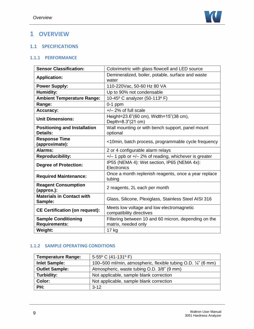
1.1.1 PERFORMANCE
Sensor Classification: Colorimetric with glass flowcell and LED source
Application: Demineralized, boiler, potable, surface and waste water
Power Supply: 110-220Vac, 50-60 Hz 80 VA
Humidity: Up to 90% not condensable
Ambient Temperature Range: 10-45º C analyzer (50-113º F)
Range: 0-1 ppm
Accuracy: +/– 2% of full scale
Unit Dimensions: Height=23.6”(60 cm), Width=15”(38 cm), Depth=8.3”(21 cm)
Positioning and Installation Details:
Wall mounting or with bench support, panel mount optional
Response Time (approximate):
<10min, batch process, programmable cycle frequency
Alarms: 2 or 4 configurable alarm relays
Reproducibility: +/– 1 ppb or +/– 2% of reading, whichever is greater
Degree of Protection: IP55 (NEMA 4): Wet section, IP65 (NEMA 4x): Electronics
Required Maintenance: Once a month replenish reagents, once a year replace tubing
Reagent Consumption (approx.):
2 reagents, 2L each per month
Materials in Contact with Sample:
Glass, Silicone, Plexiglass, Stainless Steel AISI 316
CE Certification (on request): Meets low voltage and low electromagnetic compatibility directives
Sample Conditioning Requirements:
Filtering between 10 and 60 micron, depending on the matrix, needed only
Weight: 17 kg
1.1.2 SAMPLE OPERATING CONDITIONS
Temperature Range: 5-55º C (41-131º F)
Inlet Sample: 100–500 ml/min, atmospheric, flexible tubing O.D. ¼” (6 mm)
Outlet Sample: Atmospheric, waste tubing O.D. 3/8” (9 mm)
Turbidity: Not applicable, sample blank correction
Color: Not applicable, sample blank correction
PH: 3-12

Overview
10 Waltron User Manual 3051 Hardness Analyzer
1.1.3 SIGNAL OUTPUTS
Analog Outputs: 4-20mA (galvanic isolator module available as option) or 0-5V
Serial I/O for Signals: Serial data output RS232 standard, RS485 available as option
1.1.4 OPERATIONAL CALIBRATION
Frequency/Intervals: Recommended: 7 days
Single/Multi-Point: Multi-Point: zero and mid-range
Matrix Corrections: Yes, sample blank correction
Manual/Automatic: Both
1.2 SAFETY PRECAUTIONS, INSTRUCTIONS, AND HAZARDS
1.2.1 GENERAL INFORMATION
This manual contains important information which is required for installation, start up and
operation of the Waltron 3051 Hardness Analyzer. Please read this manual carefully before
installing and placing the analyzer into service!
Pay attention to all caution and danger labels present on the analyzer and all caution and danger
statements written on this manual.
Waltron shall not be liable for errors contained herein and/or for an incorrect use of the
analyzer. The department head and analyzer’s users must be sure to read and observe the
following instructions and to apply all the national and local regulations and laws
regarding workers health and safety.
Use, maintenance, and service of this analyzer is allowed only by qualified personnel
who are fully trained on the analyzer’s operations. This personnel is intended to be
physically and mentally fit and not under effect of alcohol or/and drugs.
When the analyzer is not used it should be protected from intentional or unintentional
powering on, using a proper circuit breaker.
Failure to do so and non-observance of hazards or dangers warnings could result in death
or serious injury to the operators or damage to the analyzer.
Before using the analyzer, it is necessary to visually check for damages to safety devices
and report to your department head even if they don’t cause the analyzer to stop or
malfunction.
All the analyzer’s components are installed inside a metallic enclosure with a door
equipped with a special key opening, only endowed to qualified maintenance personnel.
1.2.2 LIST OF WARNINGS AND POTENTIAL DANGERS
The table below is a list of hazards and dangers warning labels that may be found on the analyzer
and/or in this manual. In case of these labels becoming outdated, they should be replaced with
new ones by the analyzer owner.
Overview
11 Waltron User Manual 3051 Hardness Analyzer
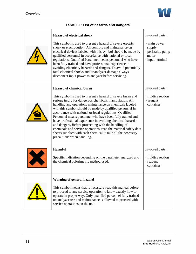
Table 1.1: List of hazards and dangers.
Hazard of electrical shock
This symbol is used to present a hazard of severe electric
shock or electrocution. All controls and maintenance on
electrical devices labeled with this symbol should be made by
qualified personnel in accordance with national or local
regulations. Qualified Personnel means personnel who have
been fully trained and have professional experience in
avoiding electricity hazards and dangers. To avoid potentially
fatal electrical shocks and/or analyzer damage always
disconnect input power to analyzer before servicing.
Involved parts:
· main power
supply
· peristaltic pump
motor
· input terminal
Hazard of chemical burns
This symbol is used to present a hazard of severe burns and
serious injury for dangerous chemicals manipulation. All
handling and operations maintenance on chemicals labeled
with this symbol should be made by qualified personnel in
accordance with national or local regulations. Qualified
Personnel means personnel who have been fully trained and
have professional experience in avoiding chemical hazards
and dangers. Before proceeding with the handling of
chemicals and service operations, read the material safety data
sheets supplied with each chemical to take all the necessary
precautions when handling.
Involved parts:
· fluidics section
· reagent
container
Harmful
Specific indication depending on the parameter analyzed and
the chemical colorimetric method used.
Involved parts:
· fluidics section
· reagent
container
Warning of general hazard
This symbol means that is necessary read this manual before
to proceed to any service operation to know exactly how to
operate in proper way. Only qualified personnel fully trained
on analyzer use and maintenance is allowed to proceed with
service operations on the unit.
Overview
12 Waltron User Manual 3051 Hardness Analyzer
1.2.3 REAGENTS
The Waltron 3051 Hardness Analyzer is based on colorimetric analysis methods, using chemical
solutions.
For the dangers and hazards regarding the chemicals used for the analysis, refer to the
appendix of the specific analytic parameter and colorimetric reaction.
Make sure that proper safety precautions are taken (e.g. using safety gloves and glasses)
during handling the chemical solutions and the reagents containers / bottles.
Read attentively the material safety data sheets of each chemical.
The bottles of the reagents must report the specific hazards and dangers labels.
1.2.4 SAMPLE
Take the proper precautions to avoid direct contact with the sample stream. It is the responsibility
of the user to collect all the information and take all the precautions regarding physical, chemical,
radiation and/or biological hazards and dangers coming from sample stream and/or sample
vapors. It is also the responsibility of the user to collect all the information and potential hazards
regarding the chemical and physical compatibility of sample stream with analyzer materials.
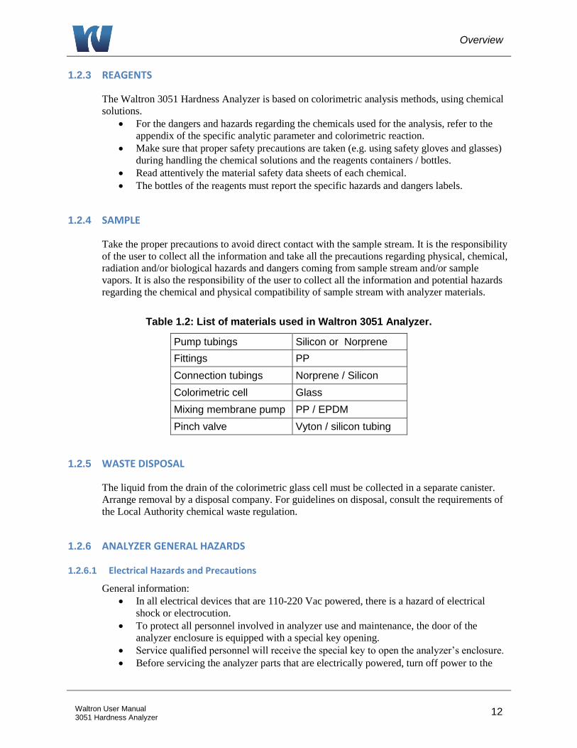
Table 1.2: List of materials used in Waltron 3051 Analyzer.
Pump tubings Silicon or Norprene
Fittings PP
Connection tubings Norprene / Silicon
Colorimetric cell Glass
Mixing membrane pump PP / EPDM
Pinch valve Vyton / silicon tubing
1.2.5 WASTE DISPOSAL
The liquid from the drain of the colorimetric glass cell must be collected in a separate canister.
Arrange removal by a disposal company. For guidelines on disposal, consult the requirements of
the Local Authority chemical waste regulation.
1.2.6 ANALYZER GENERAL HAZARDS
1.2.6.1 Electrical Hazards and Precautions
General information:
In all electrical devices that are 110-220 Vac powered, there is a hazard of electrical
shock or electrocution.
To protect all personnel involved in analyzer use and maintenance, the door of the
analyzer enclosure is equipped with a special key opening.
Service qualified personnel will receive the special key to open the analyzer’s enclosure.
Before servicing the analyzer parts that are electrically powered, turn off power to the
Overview
13 Waltron User Manual 3051 Hardness Analyzer
analyzer to avoid risks of electrocution.
To turn off power from an electrical device, it is necessary to interrupt the power line
using a circuit breaker or an isolating switch to be sure that there is no power in the area
to be serviced.
Inside the analyzer’s enclosure, the lower level of protection against direct contacts is
IP2X. The analyzer’s enclosures are IP54.
Protection against indirect contacts is guaranteed by efficient grounding of all isolated
metal masses. Grounding screw is located inside the electrical enclosure, in the lower
right position.
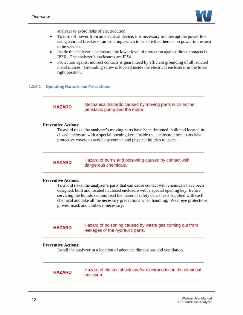
1.2.6.2 Operating Hazards and Precautions
HAZARD Mechanical hazards caused by moving parts such as the peristaltic pump and the motor.
Preventive Actions:
To avoid risks, the analyzer’s moving parts have been designed, built and located in
closed enclosure with a special opening key. Inside the enclosure, these parts have
protective covers to avoid any contact and physical injuries to users.
HAZARD Hazard of burns and poisoning caused by contact with dangerous chemicals.
Preventive Actions:
To avoid risks, the analyzer’s parts that can cause contact with chemicals have been
designed, built and located in closed enclosure with a special opening key. Before
servicing the liquids section, read the material safety data sheets supplied with each
chemical and take all the necessary precautions when handling. Wear eye protections,
gloves, mask and clothes if necessary.
HAZARD Hazard of poisoning caused by waste gas coming out from leakages of the hydraulic parts.
Preventive Actions:
Install the analyzer in a location of adequate dimensions and ventilation.
HAZARD Hazard of electric shock and/or electrocution in the electrical enclosure.

Overview
14 Waltron User Manual 3051 Hardness Analyzer
Preventive Actions:
The analyzer’s electric equipment complies with EN 60204 requirements.
To avoid risks, the analyzer’s parts that can cause hazard of electric shock and/or
electrocution have been designed, built and located in closed enclosure with a special
opening key. Inside the enclosure, these parts have protective covers and warning labels
to avoid any contact and serious injuries or death to users.
NOTE: Electrical equipment with input power and grounding must comply with the national or local regulations and laws.
Preventive Actions:
Check that the source voltage to be used corresponds with that requested by the analyzer.
Check periodically the power cord grounding in addition to the analyzer grounding.
Introduction
15 Waltron User Manual 3051 Hardness Analyzer
2 INTRODUCTION
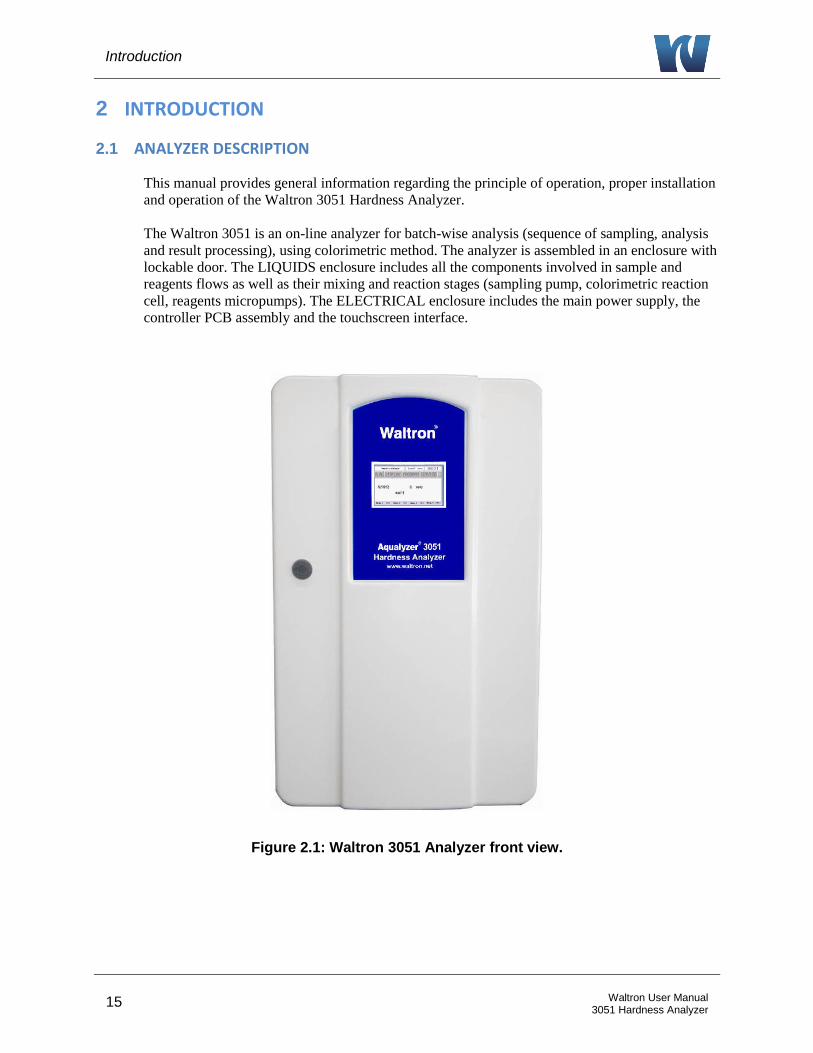
2.1 ANALYZER DESCRIPTION
This manual provides general information regarding the principle of operation, proper installation
and operation of the Waltron 3051 Hardness Analyzer.
The Waltron 3051 is an on-line analyzer for batch-wise analysis (sequence of sampling, analysis
and result processing), using colorimetric method. The analyzer is assembled in an enclosure with
lockable door. The LIQUIDS enclosure includes all the components involved in sample and
reagents flows as well as their mixing and reaction stages (sampling pump, colorimetric reaction
cell, reagents micropumps). The ELECTRICAL enclosure includes the main power supply, the
controller PCB assembly and the touchscreen interface.
Figure 2.1: Waltron 3051 Analyzer front view.
Introduction
16 Waltron User Manual 3051 Hardness Analyzer
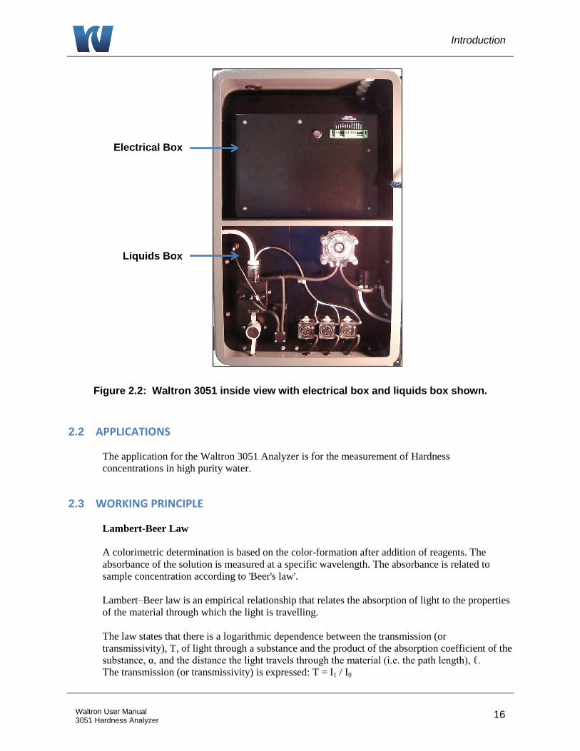
Figure 2.2: Waltron 3051 inside view with electrical box and liquids box shown.
2.2 APPLICATIONS
The application for the Waltron 3051 Analyzer is for the measurement of Hardness
concentrations in high purity water.
2.3 WORKING PRINCIPLE
Lambert-Beer Law
A colorimetric determination is based on the color-formation after addition of reagents. The
absorbance of the solution is measured at a specific wavelength. The absorbance is related to
sample concentration according to 'Beer's law'.
Lambert–Beer law is an empirical relationship that relates the absorption of light to the properties
of the material through which the light is travelling.
The law states that there is a logarithmic dependence between the transmission (or
transmissivity), T, of light through a substance and the product of the absorption coefficient of the
substance, α, and the distance the light travels through the material (i.e. the path length), ℓ.
The transmission (or transmissivity) is expressed: T = I1 / I0
Electrical Box
Liquids Box

Introduction
17 Waltron User Manual 3051 Hardness Analyzer
Absorbance for liquids is defined as the negative logarithm of the transmittance:
A = - log10T = log101/T = log10I0/I1
I0 = light intensity through the sample before colorimetric reaction
I1 = light intensity through the sample after colorimetric reaction
In most cases the absorbance has a linear correlation with the sample concentration; for a linear
calibration line just the blank and span values (i.e. concentration with zero analyte and the
maximum expected concentration) are needed. Multiple analysis at each point that are averaged
will provide a more accurate calibration line.
The absorbance ranges from 0 to 1, but it can go higher than that.
An absorbance of 0 at some wavelength means that no light of that particular wavelength
has been absorbed. The intensities of the sample and reference beam are both the same, so
the ratio I0/I1 is 1. Log10 of 1 is zero.
An absorbance of 1 happens when 90% of the light at that wavelength has been absorbed
which means that the intensity is 10% of what it would otherwise be. In that case, I0/ I1 is
100/10 (=10) and log10 of 10 is 1.
Absorption photometry (Colorimetry):
The methods used are based on the formation of a colored complex of the analyte with a color
reagent. Light with a specific wavelength is send through the reaction mixture. The absorbance
of this light by the formed complex, measured by a photometer, is related to the concentration of
the analyte.
readingsensor
referenceAbsorbance log
Figure 2.3: Color development.
Introduction
18 Waltron User Manual 3051 Hardness Analyzer
2.4 ANALYSIS CYCLE
2.4.1 PROGRAMMING COMMANDS
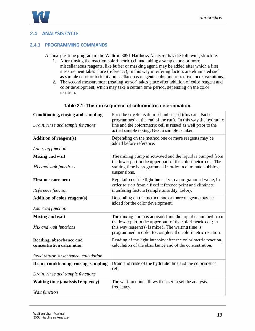
An analysis time program in the Waltron 3051 Hardness Analyzer has the following structure:
1. After rinsing the reaction colorimetric cell and taking a sample, one or more
miscellaneous reagents, like buffer or masking agent, may be added after which a first
measurement takes place (reference); in this way interfering factors are eliminated such
as sample color or turbidity, miscellaneous reagents color and refractive index variations.
2. The second measurement (reading sensor) takes place after addition of color reagent and
color development, which may take a certain time period, depending on the color
reaction.
Table 2.1: The run sequence of colorimetric determination.
Conditioning, rinsing and sampling
Drain, rinse and sample functions
First the cuvette is drained and rinsed (this can also be
programmed at the end of the run). In this way the hydraulic
line and the colorimetric cell is rinsed as well prior to the
actual sample taking. Next a sample is taken.
Addition of reagent(s)
Add reag function
Depending on the method one or more reagents may be
added before reference.
Mixing and wait
Mix and wait functions
The mixing pump is activated and the liquid is pumped from
the lower part to the upper part of the colorimetric cell. The
waiting time is programmed in order to eliminate bubbles,
suspensions.
First measurement
Reference function
Regulation of the light intensity to a programmed value, in
order to start from a fixed reference point and eliminate
interfering factors (sample turbidity, color).
Addition of color reagent(s)
Add reag function
Depending on the method one or more reagents may be
added for the color development.
Mixing and wait
Mix and wait functions
The mixing pump is activated and the liquid is pumped from
the lower part to the upper part of the colorimetric cell; in
this way reagent(s) is mixed. The waiting time is
programmed in order to complete the colorimetric reaction.
Reading, absorbance and
concentration calculation
Read sensor, absorbance, calculation
Reading of the light intensity after the colorimetric reaction,
calculation of the absorbance and of the concentration.
Drain, conditioning, rinsing, sampling
Drain, rinse and sample functions
Drain and rinse of the hydraulic line and the colorimetric
cell.
Waiting time (analysis frequency)
Wait function
The wait function allows the user to set the analysis
frequency.
Introduction
19 Waltron User Manual 3051 Hardness Analyzer
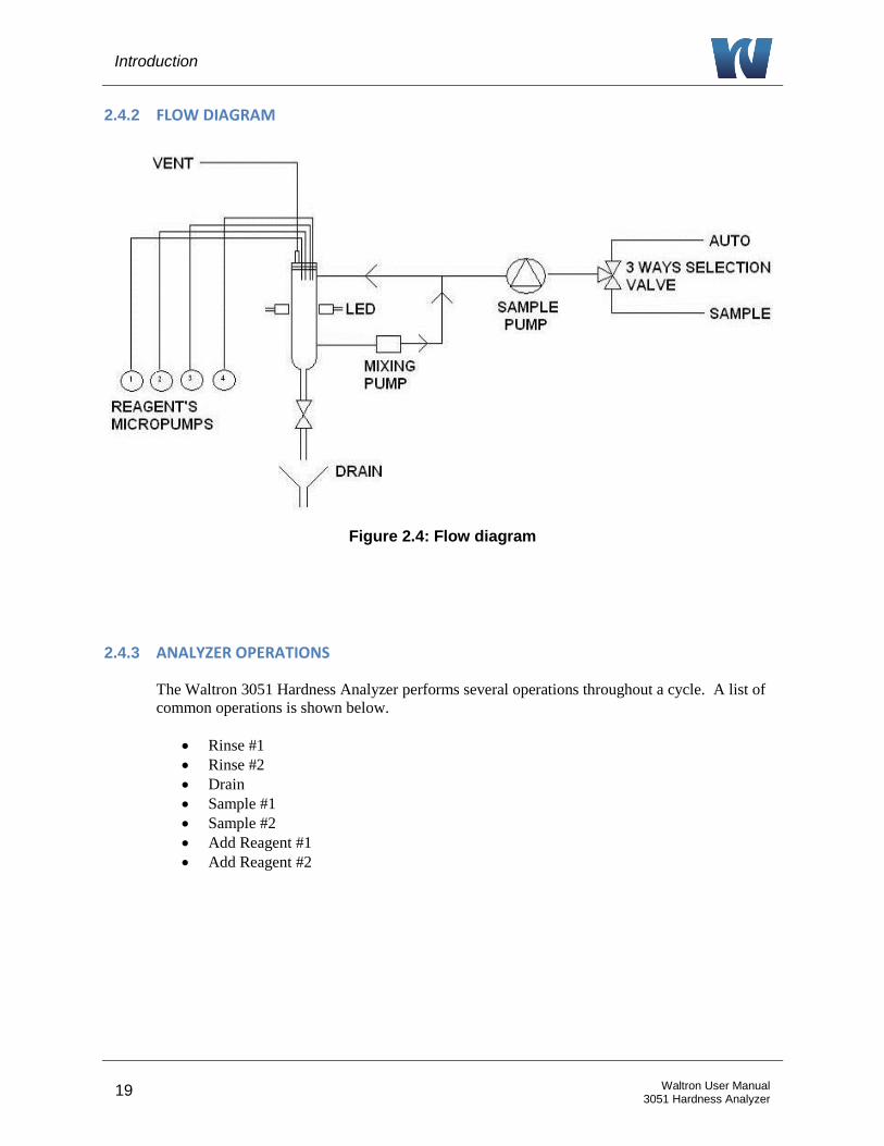
2.4.2 FLOW DIAGRAM
Figure 2.4: Flow diagram
2.4.3 ANALYZER OPERATIONS
The Waltron 3051 Hardness Analyzer performs several operations throughout a cycle. A list of
common operations is shown below.
Rinse #1
Rinse #2
Drain
Sample #1
Sample #2
Add Reagent #1
Add Reagent #2

Introduction
20 Waltron User Manual 3051 Hardness Analyzer
2.5 FAST LOOP RESERVOIR
The external reservoir, required for online applications, allows a fast circulation of the sample
coming from the sampling point. Inside the fast-loop reservoir the sample is at atmospheric
pressure and this allows the sample pump to provide the analyzer with a constant delivery of
smaple and no overpressure. In addition, the fast-loop reservoir holds a small additional quantity
of sample to avoid wrong alarms in case of short loss of sample as well as to eliminate air bubbles
from the sample line.
The stainless steel drain tubing keeps a constant water level inside the container and
allows a proper sample circulation to avoid suspended solids accumulation.
The sample flow should be adjusted to have the complete sample overflow through the
U-shaped stainless steel tube. A small hole at the stainless steel tubing allows the fast-
loop reservoir to empty for cleaning purposes just with finger pressure.
Inside the reservoir a level sensor checks for water presence. The loss of sample switch
puts the analyzer into stand-by conditions at the end of the current cycle. When the
sample flow resumes in the reservoir, the analyzer will start automatically with a new
cycle.
NOTE: In the case of dual stream units, there will be two separate fast loop reservoirs, one for each of the sample streams.
Figure 2.5: Depiction of the fast-loop reservoir.
Air to Overflow Drain Process Sample Overflow Drain
Sample to Analyzer Stream Inlet Level Switch Process Sample Inlet (behind overflow
tubing)
Introduction
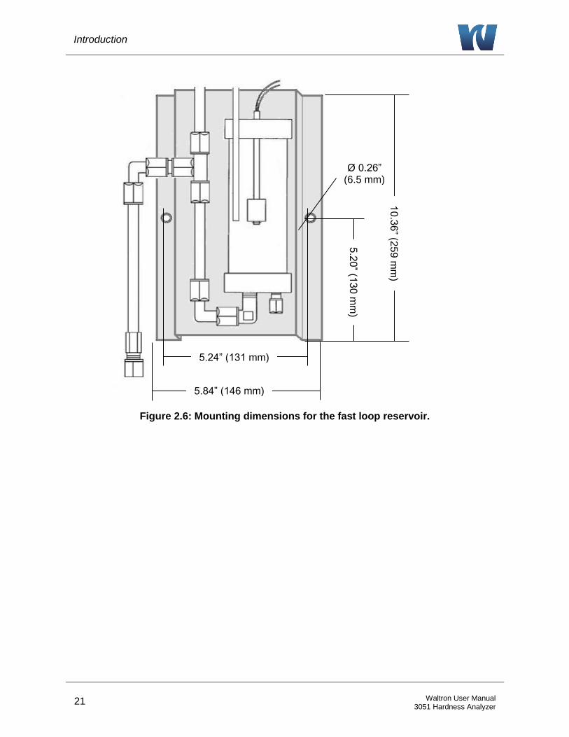
21 Waltron User Manual 3051 Hardness Analyzer
Figure 2.6: Mounting dimensions for the fast loop reservoir.
10.3
6” (2
59 m
m)
5.84” (146 mm)
5.24” (131 mm)
5.2
0” (1
30 m
m)
Ø 0.26” (6.5 mm)
Introduction
22 Waltron User Manual 3051 Hardness Analyzer
2.6 WET-SECTION BOX
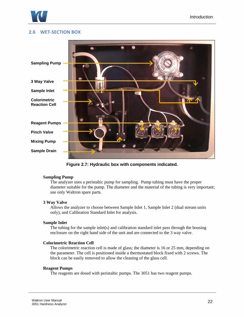
Figure 2.7: Hydraulic box with components indicated.
Sampling Pump
The analyzer uses a peristaltic pump for sampling. Pump tubing must have the proper
diameter suitable for the pump. The diameter and the material of the tubing is very important;
use only Waltron spare parts.
3 Way Valve
Allows the analyzer to choose between Sample Inlet 1, Sample Inlet 2 (dual stream units
only), and Calibration Standard Inlet for analysis.
Sample Inlet
The tubing for the sample inlet(s) and calibration standard inlet pass through the housing
enclosure on the right hand side of the unit and are connected to the 3 way valve.
Colorimetric Reaction Cell
The colorimetric reaction cell is made of glass; the diameter is 16 or 25 mm, depending on
the parameter. The cell is positioned inside a thermostated block fixed with 2 screws. The
block can be easily removed to allow the cleaning of the glass cell.
Reagent Pumps
The reagents are dosed with peristaltic pumps. The 3051 has two reagent pumps.
Sampling Pump 3 Way Valve Sample Inlet Colorimetric Reaction Cell Reagent Pumps Pinch Valve Mixing Pump
Sample Drain

Introduction
23 Waltron User Manual 3051 Hardness Analyzer
Pinch Valve
Normally-closed pinch valve to pinch or open a silicon / viton tubing O.D. ⅜ in order to
close or open the drain of the colorimetric cell. The size and the material of the tubing is very
important; use only Waltron spare parts.
Mixing Pump
The sample is mixed with reagents with a membrane mixing pump. The liquid is pumped
from the lower part to the upper part of the colorimetric cell.
Flow direction (inlet / outlet) of the pump is indicated on it with the symbols Λ and V.
Sample Drain
The tubing for the sample drain maintains a constant level of few cm of liquid on the
colorimetric cell.
2.7 ELECTRONICS
The microprocessor and its PCB assembly are located in the electronic section. It provides to
control the entire analyzing system. It handles the analyzer operations, it collects all the
information and data coming from the different analyzer devices and it controls all the I/O
apparatus to dialogue with the user touchscreen interfaces and transfer data equipments. The
connections for the external terminal block are shown in Section 3.6.2.
Figure 2.8: Electronics box.
Pass-thru Cable Glands AC Power Connections (behind cover) External Terminal Block Power Switch Electronics
Enclosure
Installation
24 Waltron User Manual 3051 Hardness Analyzer
3 INSTALLATION
3.1 RECEIVING
The Waltron 3051 Hardness Analyzer is assembled and fully tested for proper performance.
Before proceeding with analyzer installation, it is recommended to:
Check that the box and analyzer have not been damaged during transportation.
Take extreme care during analyzer unpacking and moving.
Be careful not to misplace accessories during unpacking. Refer to the packing list
included.
3.2 ANALYZER HANDLING
Take extreme care when lifting or moving the analyzer. Before moving the analyzer, it is
recommended to manually empty all of the hydraulic parts of any liquids.
3.3 LOCATION AND MOUNTING
It is recommended to install the analyzer in a suitable position:
The location is to be clean, covered and properly enclosed to provide the analyzer with
good ventilation and low dust concentration.
Operating environmental conditions are: temperature between 5 and 50°C at max 80%
relative humidity. If the temperature is below 5°C, the analyzer should be installed in a
heated cabinet.
Because of chemicals and waste gases it is absolutely necessary to have a well ventilated
location for the analyzer.
The analyzer is supplied with four mounting brackets for wall or stainless steel support
rack installation. Use 4 screws M6 or M8 to mount the analyzer.
Reagent bottles are supplied with the analyzer.
o Relative position of the reagent's bottle(s) versus reagent pump(s) is very
important.
o Respect the maximum height of about 16” (40 cm) between the bottle(s) and the
lowest edge of the analyzer panel.
The fast-loop reservoir should be mounted within reach of the sample tubing
(approximately 24” (60 cm) in length).
3.4 PRE-INSTALLATION
Before installing the analyzer, take the following precautions:
Place the analyzer close to the sample point to achieve the minimum response time; the
sample should be homogenous and representative.
The drain line should be properly dimensioned and positioned at a downward slope to
allow the drain of analyzed sample (by gravity) and the overflow coming from external
fast-loop reservoir (if used).
Installation
25 Waltron User Manual 3051 Hardness Analyzer
WARNING!
The sample drain of the analyzer must be at ambient pressure with no restriction or counter pressure. Please verify that this condition has been strictly respected during installation.
Clearance requirements for the analyzer should be about 8” (20 cm) on either side and
about 40” (100 cm) in the front.
Sufficient space for the reagent containers should be provided on the side or beneath the
analyzer.
The reagent containers should be positioned in the reagent bracket or a suitable basin in
case of spills.
NOTE: Respect the maximum height of 16” (40 cm) between the reagent's bottle(s) and the reagent's pump(s).
3.5 MOUTING SCHEMATICS
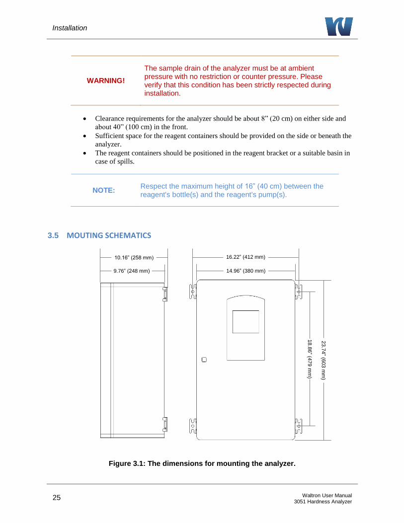
Figure 3.1: The dimensions for mounting the analyzer.
10.16” (258 mm)
9.76” (248 mm)
16.22” (412 mm)
14.96” (380 mm)
18.8
6” (4
79 m
m)
23.7
4” (6
03 m
m)

Installation
26 Waltron User Manual 3051 Hardness Analyzer
3.6 ELECTRICAL CONNECTIONS
General information:
The electrical installation should be carried out by qualified personnel in accordance with
national or local regulations. Qualified Personnel means a person who has been fully
trained and has professional experience to avoid electrical hazards and dangers.
Service qualified personnel will receive the special key to open the analyzer’s enclosure.
Before servicing the analyzer or its parts that are electrically powered, turn off power to
avoid risks of electrocution.
To turn off power from an electrical device, it is necessary to interrupt the power line
using a circuit breaker or an isolating switch to be sure that there is no power in the area
to be serviced.
Protection against indirect contacts is guaranteed by efficient grounding of all isolated
metal masses.
o Grounding screw is located in the upper left position inside the electrical
enclosure.
o It will be user’s task to periodically check and guarantee the efficiency of
analyzer’s grounding.
Users and qualified maintenance personnel must proceed as follows:
Be careful of electrical shock and/or electrocutions labels placed on the analyzer.
Always isolate power before servicing the analyzer.
In case of loss of power, the analyzer stops and automatically restarts into standby mode as soon
as power is restored.
No maintenance should be carried out on the instrument without first switching off the power.
3.6.1 AC POWER CONNECTION
The Waltron 3051 Hardness Analyzer is designed for operation with 110-220Vac, 50 Hz power.
All the connections must be made in accordance with national or local regulations. The analyzer
is equipped with a thermal switch (main power switch). It is always recommended that the
analyzer is connected to the mains via a circuit breaker or an isolating switch installed near the
unit.
To make changes to the AC power connections, it is necessary to remove the electronics
enclosure cover. The AC power connections are fed to a connector that sends the power to the
ON / OFF switch before reaching the analyzer. The connections are shown below in Figure 3.2.

Installation
27 Waltron User Manual 3051 Hardness Analyzer
3.6.2 USER SIGNAL CONNECTIONS
The analyzer provides an External Terminal Block on the outside of the Electronics Enclosure. It
allows the operator to connect to an external device such as a sequencer or sampler, monitor the
4-20mA ouputs and monitor alarm relays. The external terminal block can be configured from
the SERVICE Screen.
Table 3.1 below shows the terminal contact labels starting with pin 1 on the left.
Figure 3.2: Electrical connections for user connections and power connections.
Table 3.1: Terminal block pin locations.
Pin Number Terminal Label Description
1 - Input NO contact from an External Device to tell the analyzer to take a measurement. 2 + Input
3 - Signal 2 4-20mA output for Sample 2 Measurement
4 + Signal 2
5 - Signal 1 4-20mA output for Sample 1 Measurement
6 + Signal 1
7 COM ½ Common for Relay 1 and 2
8 OUT Relay 1 Alarm Relay 1 NO Contacts
9 OUT Relay 2 Alarm Relay 2 NO Contacts
10 OUT Relay 3 Alarm Relay 3 NO Contacts
11 OUT Relay 4 Alarm Relay 4 NO Contacts
12 COM 3/4 Common for Relay 3 and 4
Installation
28 Waltron User Manual 3051 Hardness Analyzer
3.7 REAGENT INFORMATION
The Waltron 3051 Hardness Analyzer uses 2 reagents for the colorimetric measurement.
Reagent 1: Cresolphthalein Reagent
Reagent 2: Ethanolamine Reagent
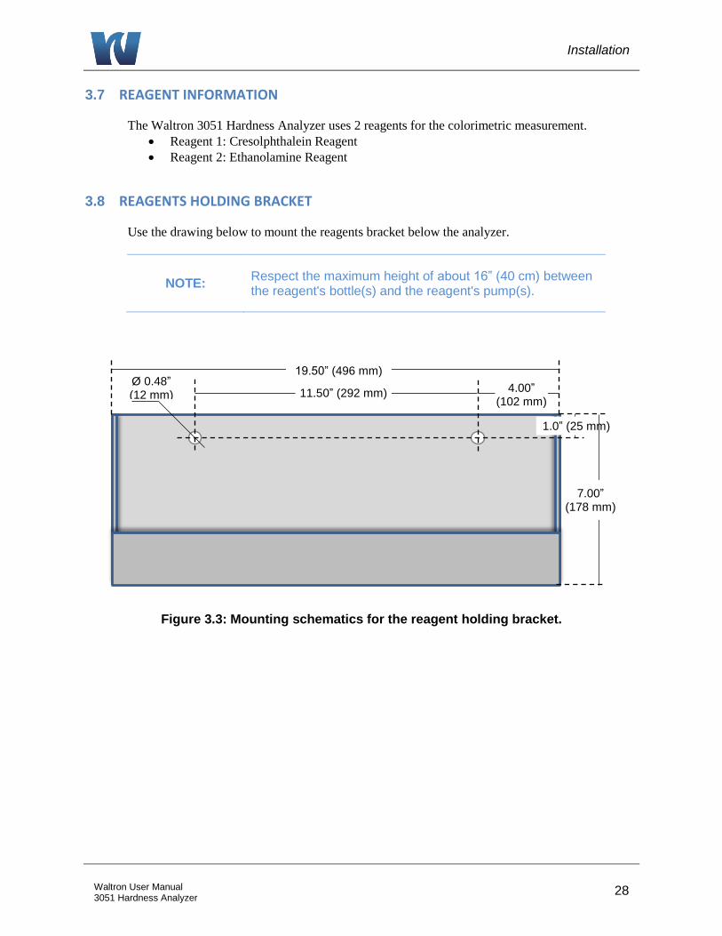
3.8 REAGENTS HOLDING BRACKET
Use the drawing below to mount the reagents bracket below the analyzer.
NOTE: Respect the maximum height of about 16” (40 cm) between the reagent's bottle(s) and the reagent's pump(s).
Figure 3.3: Mounting schematics for the reagent holding bracket.
19.50” (496 mm) Ø 0.48” (12 mm)
1.0” (25 mm)
7.00” (178 mm)
4.00” (102 mm)
11.50” (292 mm)
Analyzer Initial Start-Up
29 Waltron User Manual 3051 Hardness Analyzer
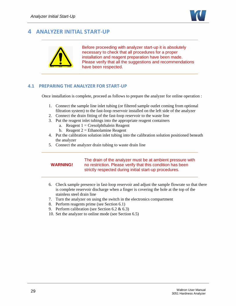
4 ANALYZER INITIAL START-UP
Before proceeding with analyzer start-up it is absolutely necessary to check that all procedures for a proper installation and reagent preparation have been made. Please verify that all the suggestions and recommendations have been respected.
4.1 PREPARING THE ANALYZER FOR START-UP
Once installation is complete, proceed as follows to prepare the analyzer for online operation :
1. Connect the sample line inlet tubing (or filtered sample outlet coming from optional
filtration system) to the fast-loop reservoir installed on the left side of the analyzer
2. Connect the drain fitting of the fast-loop reservoir to the waste line
3. Put the reagent inlet tubings into the appropriate reagent containers
a. Reagent 1 = Cresolphthalein Reagent
b. Reagent 2 = Ethanolamine Reagent
4. Put the calibration solution inlet tubing into the calibration solution positioned beneath
the analyzer
5. Connect the analyzer drain tubing to waste drain line
WARNING! The drain of the analyzer must be at ambient pressure with no restriction. Please verify that this condition has been strictly respected during initial start-up procedures.
6. Check sample presence in fast-loop reservoir and adjust the sample flowrate so that there
is complete reservoir discharge when a finger is covering the hole at the top of the
stainless steel drain line
7. Turn the analyzer on using the switch in the electronics compartment
8. Perform reagents prime (see Section 6.1)
9. Perform calibration (see Section 6.2 & 6.3)
10. Set the analyzer to online mode (see Section 6.5)
User Interface
30 Waltron User Manual 3051 Hardness Analyzer
5 USER INTERFACE
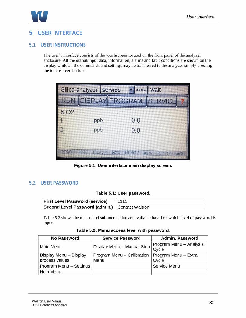
5.1 USER INSTRUCTIONS
The user’s interface consists of the touchscreen located on the front panel of the analyzer
enclosure. All the output/input data, information, alarms and fault conditions are shown on the
display while all the commands and settings may be transferred to the analyzer simply pressing
the touchscreen buttons.
Figure 5.1: User interface main display screen.
5.2 USER PASSWORD
Table 5.1: User password.
First Level Password (service) 1111
Second Level Password (admin.) Contact Waltron
Table 5.2 shows the menus and sub-menus that are available based on which level of password is
input.
Table 5.2: Menu access level with password.
No Password Service Password Admin. Password
Main Menu Display Menu – Manual Step Program Menu – Analysis Cycle
Display Menu – Display process values
Program Menu – Calibration Menu
Program Menu – Extra Cycle
Program Menu – Settings Service Menu
Help Menu
User Interface
31 Waltron User Manual 3051 Hardness Analyzer
5.3 MAIN SCREEN
The main screen displays:
Name of the analysis program (Hardness Analyzer)
Login **** window (two levels of password); pressing on **** the user can input the 4
number password
Buttons that allow access the sub-menus (Run, Display, Program, Service and ?)
Value (ppm or ppb) of the last analysis
Alarms / relays
Active step of the analysis in progress
Reagent(s) consumption (%)
Table 5.3: Analyzer operating statuses.
ANALYZER OPERATING STATUS
STAND-BY The analyzer is waiting for a user’s command (for example when the analyzer is switched on after a shutdown), after single cycle analysis, or when the operator has forced a stop in stand-by at the end of the current online / single cycle by pressing the button previously activated a second time.
SINGLE CYCLE
The analyzer is performing a single analysis cycle. As soon as the cycle is completed the analyzer will go into the stand-by condition.
ON-LINE The analyzer is performing a continuous cyclic analysis based on the steps set in the PROGRAM menu (Analysis Cycle) and started when the START ON LINE button has been pressed. As soon as the analyzer completes an analysis cycle, it will restart with a new analysis. This condition is identified as the online condition.
MANUAL STOP
The analyzer has been forced to stop. A message in the main menu shows the “manual stop” and the fault alarm is initialized.
Table 5.4: Main menu button descriptions.
MAIN MENU BUTTONS
RUN This menu allows the user to put the analyzer into online measurement mode or run a single analysis cycle on stream 1 or stream 2. The user can also stop the analyzer with the emergency stop button.
DISPLAY This menu displays all analysis data, the active step of the current analysis cycle with the time counter, the sensor's signal trend graph, and allows access to the manual step functions.
PROGRAM This menu allows access to the calibration menu, enabling and disabling the loss of sample alarm, the 4-20 mA output, and settings of the analyzer.
SERVICE Second level admin password required. This menu allows access to the analysis parameter, time, blank value, and regulation of the 4-20 mA output, led, and reference.
? This menu shows the help user guide.
User Interface
32 Waltron User Manual 3051 Hardness Analyzer
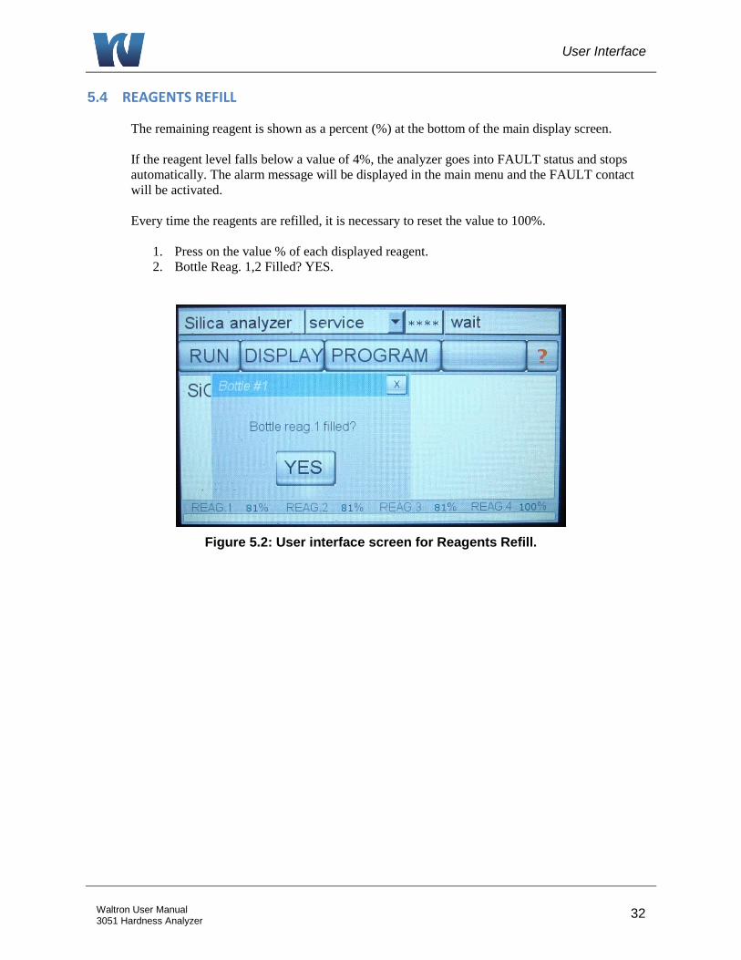
5.4 REAGENTS REFILL
The remaining reagent is shown as a percent (%) at the bottom of the main display screen.
If the reagent level falls below a value of 4%, the analyzer goes into FAULT status and stops
automatically. The alarm message will be displayed in the main menu and the FAULT contact
will be activated.
Every time the reagents are refilled, it is necessary to reset the value to 100%.
1. Press on the value % of each displayed reagent.
2. Bottle Reag. 1,2 Filled? YES.
Figure 5.2: User interface screen for Reagents Refill.

User Interface
33 Waltron User Manual 3051 Hardness Analyzer
5.5 RUN MENU
Figure 5.3: User interface after pressing the RUN Menu.
START ON-LINE:
This button puts the analyzer into continuous online operation. The analyzer will perform a
continuous cyclic analysis based on the steps set in the PROGRAM menu (Analysis Cycle).
This condition is identified as online and ONLINE is displayed on the button. Pressing the
button again will cause the analyzer to finish the cycle in progress and put the analyzer in
stand-by mode.
CH 1:
This command will perform a single analysis cycle on stream 1. At the end of the cycle, the
analyzer will go into stand-by mode and wait for the user’s next command.
CH 2 (available on dual stream units only):
This command will perform a single analysis cycle on stream 2. At the end of the cycle, the
analyzer will go into stand-by mode and wait for the user’s next command.
EXTRA:
This command will perform a cycle based on the programming of the extra cycle. The
default programming for the extra cycle is set to a CALIBRATION cycle.
EMERGENCY STOP:
This command will immediately stop the analyzer at the current step of the analysis in
progress. The analyzer will go into the MANUAL STOP condition. On the main screen
appear the message “manual stop” red coloured and the FAULT alarm contact will be
activated. To restart the analyzer after an emergency stop, it is necessary to reset the fault by
pressing the yellow colored RESET EM. STOP. This will force the analyzer to stand-by
conditions.
User Interface
34 Waltron User Manual 3051 Hardness Analyzer
5.6 DISPLAY MENU
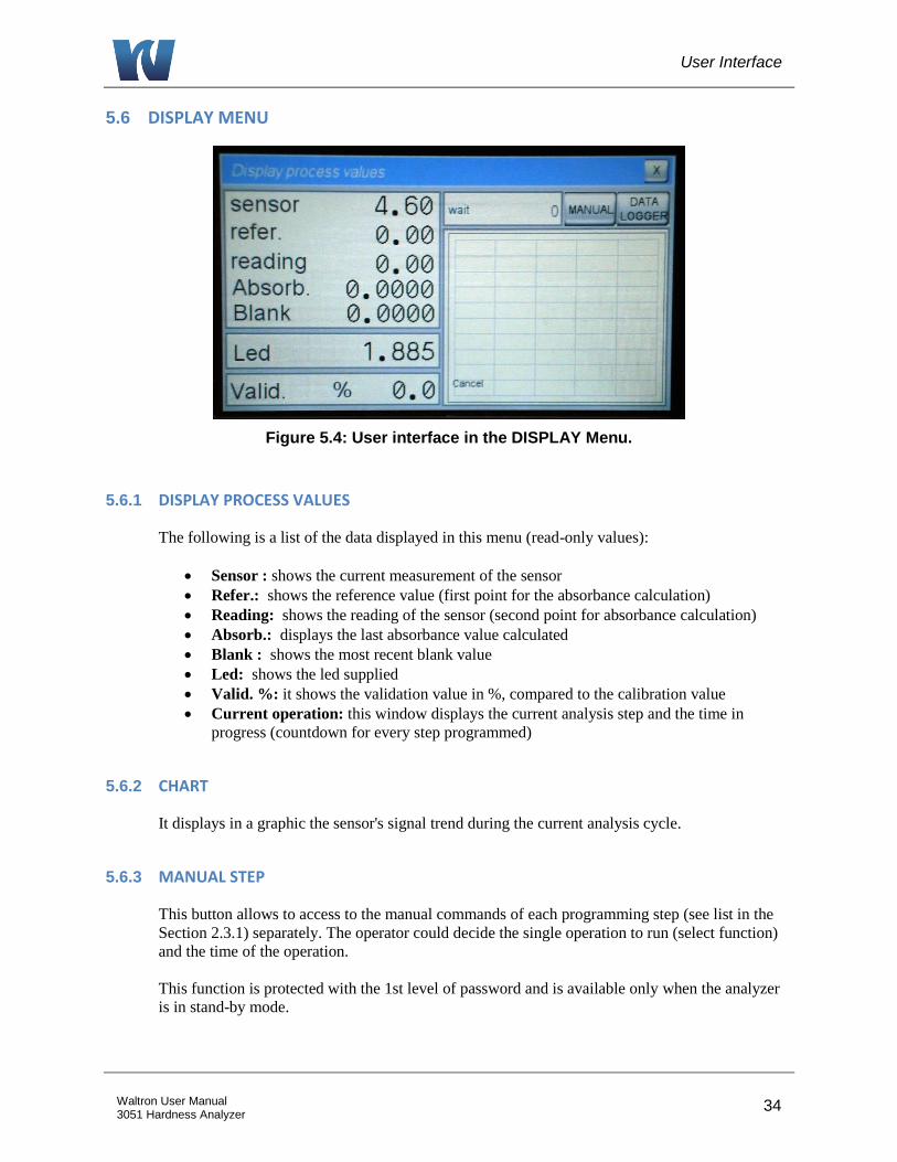
Figure 5.4: User interface in the DISPLAY Menu.
5.6.1 DISPLAY PROCESS VALUES
The following is a list of the data displayed in this menu (read-only values):
Sensor : shows the current measurement of the sensor
Refer.: shows the reference value (first point for the absorbance calculation)
Reading: shows the reading of the sensor (second point for absorbance calculation)
Absorb.: displays the last absorbance value calculated
Blank : shows the most recent blank value
Led: shows the led supplied
Valid. %: it shows the validation value in %, compared to the calibration value
Current operation: this window displays the current analysis step and the time in
progress (countdown for every step programmed)
5.6.2 CHART
It displays in a graphic the sensor's signal trend during the current analysis cycle.
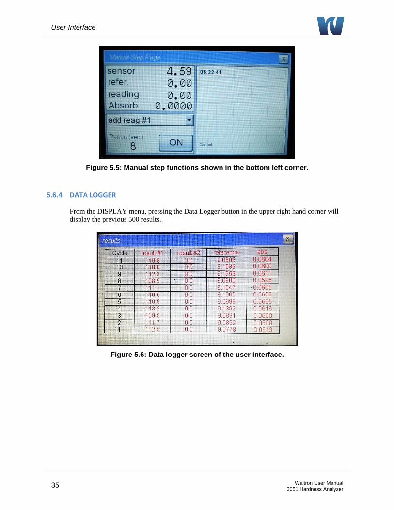
5.6.3 MANUAL STEP
This button allows to access to the manual commands of each programming step (see list in the
Section 2.3.1) separately. The operator could decide the single operation to run (select function)
and the time of the operation.
This function is protected with the 1st level of password and is available only when the analyzer
is in stand-by mode.
User Interface
35 Waltron User Manual 3051 Hardness Analyzer
Figure 5.5: Manual step functions shown in the bottom left corner.
5.6.4 DATA LOGGER
From the DISPLAY menu, pressing the Data Logger button in the upper right hand corner will
display the previous 500 results.
Figure 5.6: Data logger screen of the user interface.
User Interface
36 Waltron User Manual 3051 Hardness Analyzer
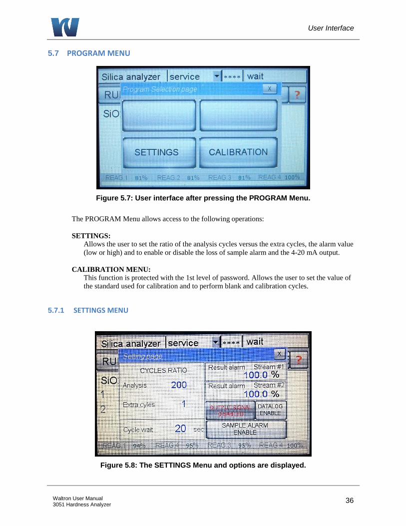
5.7 PROGRAM MENU
Figure 5.7: User interface after pressing the PROGRAM Menu.
The PROGRAM Menu allows access to the following operations:
SETTINGS:
Allows the user to set the ratio of the analysis cycles versus the extra cycles, the alarm value
(low or high) and to enable or disable the loss of sample alarm and the 4-20 mA output.
CALIBRATION MENU:
This function is protected with the 1st level of password. Allows the user to set the value of
the standard used for calibration and to perform blank and calibration cycles.
5.7.1 SETTINGS MENU
Figure 5.8: The SETTINGS Menu and options are displayed.
User Interface
37 Waltron User Manual 3051 Hardness Analyzer
Cycles ratio: Programs the ratio of the analysis cycles versus the extra cycle (calibration cycle).
For example, 400 analysis to 1 extra cycle means that every 400 analysis cycles the analyzer will
perform 1 calibration cycle.
Cycle wait: Sets the time between analysis cycles when the analyzer is in on-line mode.
Result alarm: Programs the low / high value alarm. The alarm is expressed in % of the full
scale.
Output Signal: Enables / disables the 4-20 mA output.
Datalog: Enables / disables the internal data logger.
Sample Alarm: Enables / disables the loss of sample alarm.
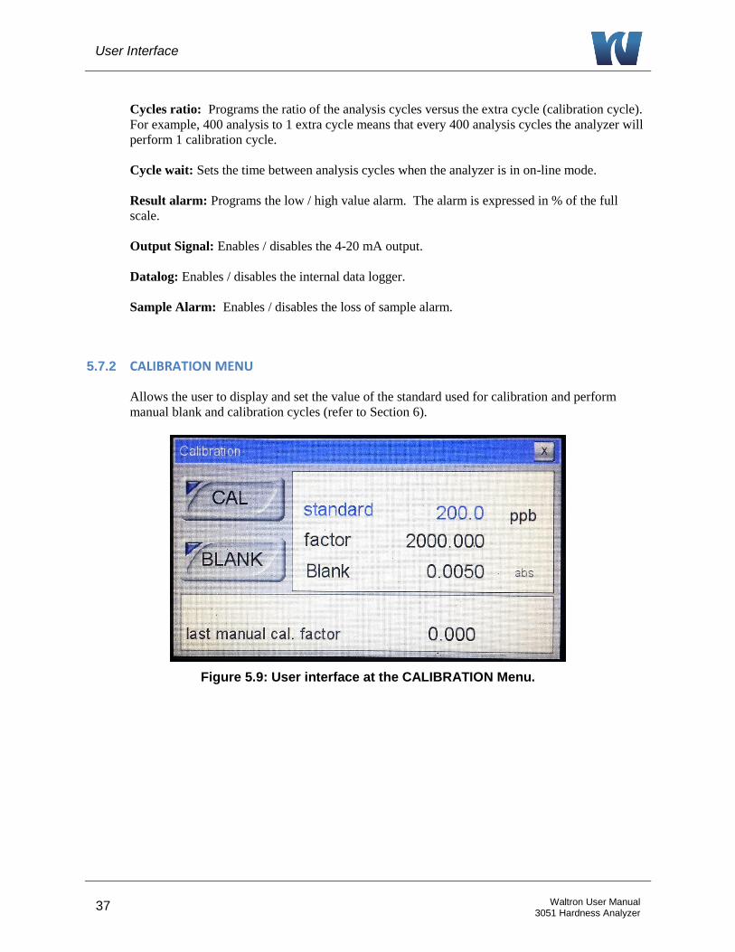
5.7.2 CALIBRATION MENU
Allows the user to display and set the value of the standard used for calibration and perform
manual blank and calibration cycles (refer to Section 6).
Figure 5.9: User interface at the CALIBRATION Menu.
User Interface
38 Waltron User Manual 3051 Hardness Analyzer
5.8 SERVICE MENU
Acess to the SERVICE Menu requires the second level password for the admin login. The
SERVICE Menu allows the user to configure the external terminal block connections.
Configure the External Control
On the Service screen change the External Input selection from NONE to either ONLINE or
EXTRA CYCLE (i.e., Calibration).
Setting the range for the 4-20mA Sample 1 Output
Set the range of the 4-20mA Sample 1 Output with the F Scale1 selection. The default range
is equal to the range of the analyzer.
Setting the range for the 4-20mA Sample 2 Output
Set the range of the 4-20mA Sample 2 Output with the F Scale2 selection. The default range
is equal to the range of the analyzer. This setting only applies to dual stream analyzers.
Configuring Relay 1, 2, 3 and 4
There are 4 cells on the service screen to configure Relay 1, Relay 2, Relay 3 and Relay 4.
Touch one of these cells and select the parameter to activate the relay:
Result Alarm – The measurement is greater than the % specified on the Settings screen. For
example: If the Result Alarm on the Settings screen is set to greater than 50%, the relay will
close when the measurement goes above 50% of the analyzer range.
Loss of Sample 1 – The relay will close when the flow on Sample 1 is lost.
Loss of Sample 2 – The relay will close when the flow on Sample 2 is lost.
Fault Alarm – The relay will close when a Fault Alarm occurs such as
- Pressing the EMERGENCY STOP button. Alarm is cleared by pressing RESET in the
RUN window.
- Reagent went below 4%. Alarm Cleared by refilling reagent bottles and setting the level
to 100%.
Cycle Command – When testing the relay, set the relay mode to “Cycle Command”.
GO to the Display screen and press the Manual button.
Scroll through the options and select Relay #1.
Set the activation duration and press ON.
The Relay #1 contacts will close for the designated duration.
User Interface
39 Waltron User Manual 3051 Hardness Analyzer
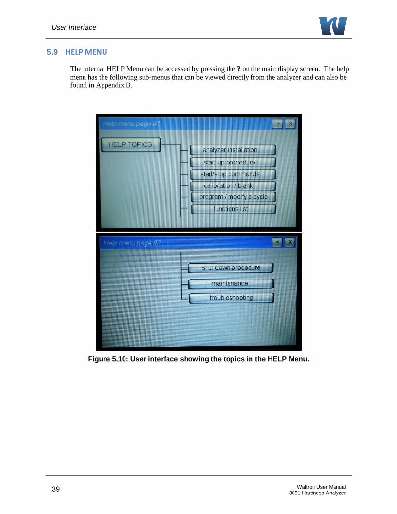
5.9 HELP MENU
The internal HELP Menu can be accessed by pressing the ? on the main display screen. The help
menu has the following sub-menus that can be viewed directly from the analyzer and can also be
found in Appendix B.
Figure 5.10: User interface showing the topics in the HELP Menu.
Operation
40 Waltron User Manual 3051 Hardness Analyzer
6 OPERATION
Colorimetry is a relative method, therefore an initial calibration is needed before measurement
can be performed. This is done using standard solutions and analyzing them in the same way as
the sample.
In order to ensure correct measurement performances, the analyzer should be calibrated
periodically. The blank is taken with DI water. The system slope is controlled by a comparison to
a standard solution of known concentration.
Calibration allows the analyzer to adjust:
Blank of the system
Slope of the system (factor calibration)
The calibration can be done manually or automatically.
6.1 REAGENTS PRIME
Prior to the initial calibration of the analyzer, the reagent lines must be primed. This procedure
should also be performed every time the reagents are refilled or replaced.
1. Login with the 1st level service password (1111).
2. Press the DISPLAY button on the touchscreen and then press the button MANUAL
STEP.
3. Select SAMPLE function for 20 seconds.
4. Select ADD REAG (1,2) functions for 40 seconds each in order to prime the three
reagent lines. Visually confirm that reagent is being drawn into the lines and into the
flowcell. If no reagent is seen, it may be necessary to repeat the ADD REAG function.
5. Select DRAIN function for 5 seconds.
6. Select SAMPLE function for 20 seconds.
7. Repeat steps 5 and 6 to rinse the flowcell.
8. Check the drain tube of the pinch valve is correctly positioned and select the DRAIN
function for 5 seconds.
6.2 BLANK CALIBRATION
A blank calibration should be performed after reagent replacement and every time a manual
calibration is required.
1. Login with the 1st level service password (1111).
2. Disconnect the sample tubing from the fast-loop reservoir and connect it to a DI water
source.
3. Perform an analysis cycle by pressing the RUN Menu and selecting CH 1.
It is recommended to proceed with a blank refreshment after performing three
analysis cycles with DI water to flush the system.
The absorbance detected by the analyzer is assumed to be absorbance produced by
reagent(s) and DI water.
4. To store this value as the blank, from the PROGRAM menu, select the CALIBRATION
Operation
41 Waltron User Manual 3051 Hardness Analyzer
Menu.
5. Press and hold down the BLANK key.
This will refresh the stored BLANK value; it can be refreshed only after a
completed analysis cycle with the analyzer in stand-by mode.
6. Reconnect the sample line to the fast-loop reservoir.
6.3 SLOPE (FACTOR) CALIBRATION
A manual factor (slope) calibration should be performed during the initial start-up, after reagent
replacement, and after any period of extended shut-down. The recommended and default setting
for automatic calibration is approximately once per week.
1. Login with the 1st level service password (1111).
2. Connect the CAL tube to the calibration standard.
3. Check that the calibration standard is the correct concentration.
a. From the PROGRAM Menu, select CALIBRATION.
b. The concentration of the standard is displayed in blue.
c. To change the standard concentration, press the displayed standard value.
d. Type the new concentration and select ENT.
4. From the RUN Menu, select EXTRA. The analyzer will perform a calibration cycle and
store the new calibration factor.
5. Perform an EXTRA Cycle two to three times with the calibration standard to ensure a
repeatable calibration factor.
6. To check the value of the calibration factor, from the PROGRAM Menu select
CALIBRATION to open the calibration menu window.
6.4 SINGLE ANALYSIS CYCLE
The analyzer can be set to run either in continuous analysis mode or single analysis mode.
Follow the steps below to perform a single analysis cycle.
NOTE: When starting the analyzer for the first time or restarting it from any period of shutdown, do not proceed to run an analysis cycle until a calibration has been performed.
1. Connect the sample tubing to the fast-loop reservoir and turn on sample flow to the fast
loop reservoir.
2. Check that the sample fills the fast loop reservoir so that the float switch rises and sample
is being discharged from the overflow drain.
3. Perform an analysis cycle by pressing the RUN Menu and selecting CH 1.
The absorbance detected by the analyzer is used along with the blank and
calibration values to determine a concentration in ppb.
4. When the analyzer has finished the analysis cycle, the concentration reading will be
displayed on the main screen. The result can also be found in the data logger.
5. The analysis returns to standby mode and waits for another user command.
Operation
42 Waltron User Manual 3051 Hardness Analyzer
6.5 ONLINE MEASUREMENT
In online mode, the analyzer will run perform consecutive analysis cycles until it is manually
stopped or the out of sample alarm is tripped.
NOTE:
When starting the analyzer for the first time or restarting it from any period of shutdown, do not proceed to put the analyzer into online operation until a calibration has been performed.
1. Connect the sample tubing to the fast-loop reservoir and turn on sample flow to the fast
loop reservoir.
2. Check that the sample fills the fast loop reservoir so that the float switch rises and sample
is being discharged from the overflow drain.
3. Put the analyzer into online measurement mode by pressing the RUN Menu and selecting
START ON LINE.
The absorbance detected by the analyzer is used along with the blank and
calibration values to determine a concentration in ppb.
4. When the analyzer has finished the analysis cycle, the concentration reading will be
displayed on the main screen. The new result and previous results are stored in the data
logger (up to 500 measurement results).
5. The analyzer will wait the user defined amount of time (see Section 5.7.1) and then
proceed to run additional analysis cycles.
6. To bring the analyzer out of online operation, press the RUN Menu. The top box where
START ONLINE was previously, will now be blank and dark gray. Pressing this box
will tell the analyzer to complete the current analysis cycle and go into stand-by mode at
its completion.
6.6 GRAB SAMPLE
The grab sample feature allows the user to measure the concentration of an external sample.
NOTE: When starting the analyzer for the first time or restarting it from any period of shutdown, do not proceed to run a grab sample analysis until a calibration has been performed.
1. If the analyzer is in online operation, it is necessary to put it into standby mode.
Press the RUN Menu and select the START ON LINE button (blank, dark gray box
on the top of the RUN Menu).
The analyzer will finish the analysis cycle that is currently in progress and go into
standby mode.
2. Turn off sample flow to the fast loop reservoir.
3. Disconnect the sample tubing from the fast-loop reservoir and connect it to the grab
sample source.
The grab sample source should have at least 200 ml of sample present.
4. Perform an analysis cycle by pressing the RUN Menu and selecting CH 1.
Operation
43 Waltron User Manual 3051 Hardness Analyzer
5. When the analyzer has finished the grab sample analysis cycle, the concentration reading
will be displayed on the main screen. The result can also be found in the data logger.
6. The analysis returns to standby mode and waits for another user command.
7. When the user is finished with the grab sample analysis, make sure to reconnect the
sample tubiing to the fast loop resevoir.
8. Turn on sample flow to the fast loop resevoir.
9. Put the analyzer back into online operation mode by pressing the RUN Menu and
selecting START ON LINE.
6.7 EMERGENCY STOP
The analyzer has an emergency stop function that will stop the analyzer immediately during any
analysis cycle that it is performing.
1. Press the RUN Menu.
2. Select EMERGENCY STOP.
The analyzer will stop its current function and return to the main display screen.
The emergency stop fault alarm will be activated.
3. To put the analyzer into standby mode after an emergency stop, press the RUN Menu.
4. The menu will now show RESET in the posistion that emergency stop was listed
previously.
5. Select RESET to deactivate the alarms and return the analyzer to the main display screen
in standby mode.
NOTE: After initiating an emergency stop, there may be sample and reagents remaining in the analyzer. It will be necessary to flush the system before performing a new analysis cycle.
Maintenance
44 Waltron User Manual 3051 Hardness Analyzer
7 MAINTENANCE
7.1 SCHEDULED MAINTENANCE
Basic maintenance of the Waltron 3051 Analyzer requires that the reagent containers are refilled
or replaced and that the colorimetric cell is cleaned on a regular basis. In addition, the user
should perform a regular 'visual overall-check' of the wet part for immediate corrective measures,
e.g. in case of leakages etc. Cleaning of the analyzer cabinet is best performed using a soft, non-
aggressive cleaner.
The use of a logbook for cataloging reagent refilling, corrective measures and scheduled
maintenance is strongly recommended.
During the performance of the basic maintenance work, as described in this chapter, the analyzer
can not be operational. Prior to the maintenance work, all necessary precautions regarding
personal safety (protective clothing, safety glasses etc.) are to be taken into consideration.
Always be sure to label and rinse all connected tubing with water prior to removal.
Waltron Colorimeter is based on colorimetric analysis methods, using chemical solutions. Make sure that proper safety precautions are taken (e.g. using safety gloves and glasses) during handling the chemical solutions.
List of scheduled maintenance:
Visual check
Everytime that it is possible, visually check the following items:
Liquid leakages
Cell sample level (during cycle)
Glass cell cleaness condition
Reagent level %
Monthly
Visual overall check
Colorimetric cell cleaning
Reagent(s) replacement (reset reagent counters)
Reagent pump(s) priming
Calibration blank with DI water, slope with calibration solution
Every 2 months
Pinch valve drain tubing replacement
Every 4 months
Peristaltic pumps tubing replacement
Maintenance
45 Waltron User Manual 3051 Hardness Analyzer
Every 6 months
3 ways valve cleaning, manually with a syringe
Colorimetric cell o-ring replacement
Fittings cleaning / replacement
Annually
Hydraulics and sample tubing replacement
Analyzer general inspection (for qualified personnel only)
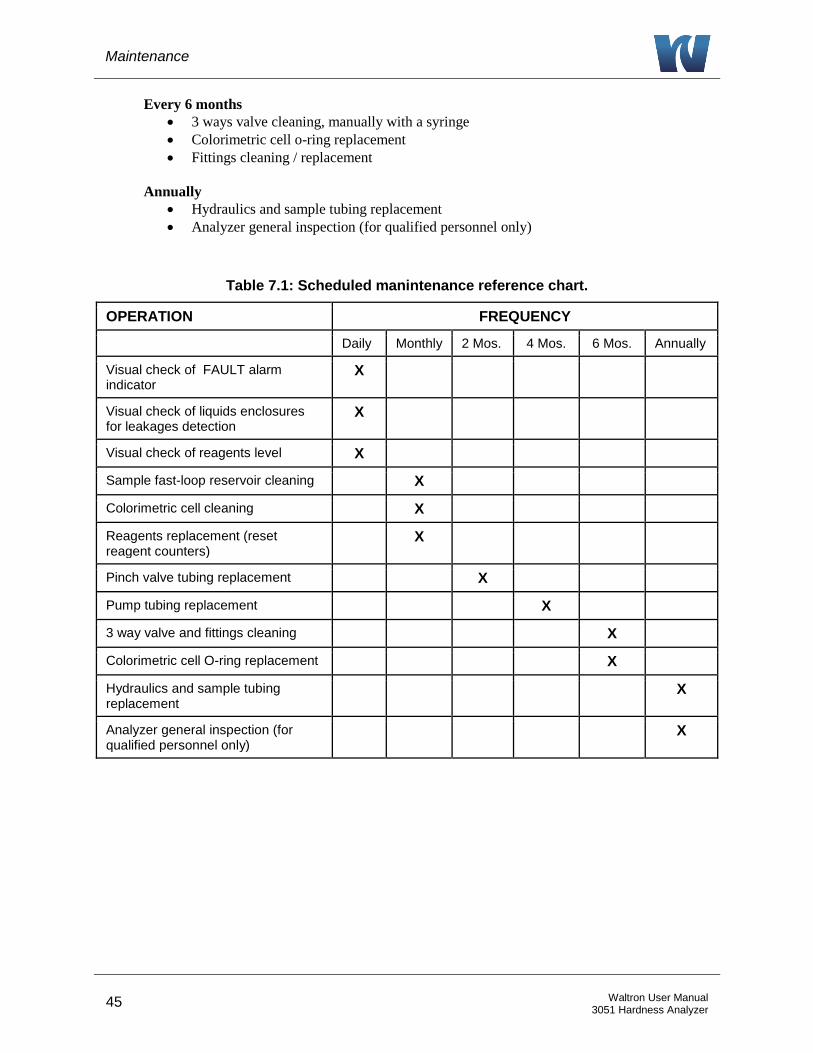
Table 7.1: Scheduled manintenance reference chart.
OPERATION FREQUENCY
Daily Monthly 2 Mos. 4 Mos. 6 Mos. Annually
Visual check of FAULT alarm indicator
X
Visual check of liquids enclosures for leakages detection
X
Visual check of reagents level X
Sample fast-loop reservoir cleaning X
Colorimetric cell cleaning X
Reagents replacement (reset reagent counters)
X
Pinch valve tubing replacement X
Pump tubing replacement X
3 way valve and fittings cleaning X
Colorimetric cell O-ring replacement X
Hydraulics and sample tubing replacement
X
Analyzer general inspection (for qualified personnel only)
X
Maintenance
46 Waltron User Manual 3051 Hardness Analyzer
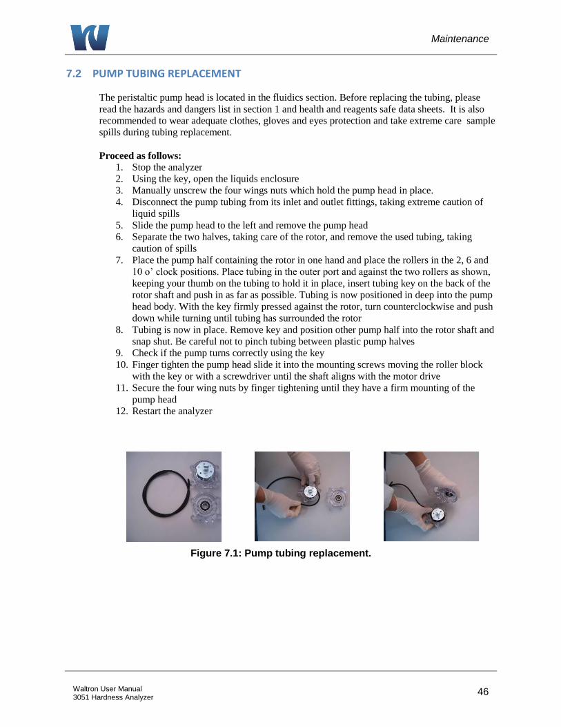
7.2 PUMP TUBING REPLACEMENT
The peristaltic pump head is located in the fluidics section. Before replacing the tubing, please
read the hazards and dangers list in section 1 and health and reagents safe data sheets. It is also
recommended to wear adequate clothes, gloves and eyes protection and take extreme care sample
spills during tubing replacement.
Proceed as follows:
1. Stop the analyzer
2. Using the key, open the liquids enclosure
3. Manually unscrew the four wings nuts which hold the pump head in place.
4. Disconnect the pump tubing from its inlet and outlet fittings, taking extreme caution of
liquid spills
5. Slide the pump head to the left and remove the pump head
6. Separate the two halves, taking care of the rotor, and remove the used tubing, taking
caution of spills
7. Place the pump half containing the rotor in one hand and place the rollers in the 2, 6 and
10 o’ clock positions. Place tubing in the outer port and against the two rollers as shown,
keeping your thumb on the tubing to hold it in place, insert tubing key on the back of the
rotor shaft and push in as far as possible. Tubing is now positioned in deep into the pump
head body. With the key firmly pressed against the rotor, turn counterclockwise and push
down while turning until tubing has surrounded the rotor
8. Tubing is now in place. Remove key and position other pump half into the rotor shaft and
snap shut. Be careful not to pinch tubing between plastic pump halves
9. Check if the pump turns correctly using the key
10. Finger tighten the pump head slide it into the mounting screws moving the roller block
with the key or with a screwdriver until the shaft aligns with the motor drive
11. Secure the four wing nuts by finger tightening until they have a firm mounting of the
pump head
12. Restart the analyzer
Figure 7.1: Pump tubing replacement.

Analyzer Shut-Down
47 Waltron User Manual 3051 Hardness Analyzer
8 ANALYZER SHUT-DOWN
It is important to know that the analyzer should run continuously, if possible. For a short
downtime of the 3051 analyzer (from 1 to 3 days), it is recommended to put all the inlet tubing
(reagents and sample source) in a DI water source and leave the unit running in these conditions.
For long shut down period, please proceed as follows:
1. Replace the reagents in the container with distilled water and perform a priming of all the
pumps with DI water.
a. Login with the 1st level service password (1111).
b. Press DISPLAY > MANUAL > STEP > ADD REAG 1,2 for 40 seconds.
2. Disconnect the sample line and fill the fast-loop reservoir (if present) with DI water.
3. Run the analyzer for at least 2 cycles with all of the reagent tubes placed in a DI water
container.
4. Empty the hydraulic line of water.
5. Put the analyzer in stand-by mode.
6. Turn off the analyzer main power by disconnecting the plug from the power line.
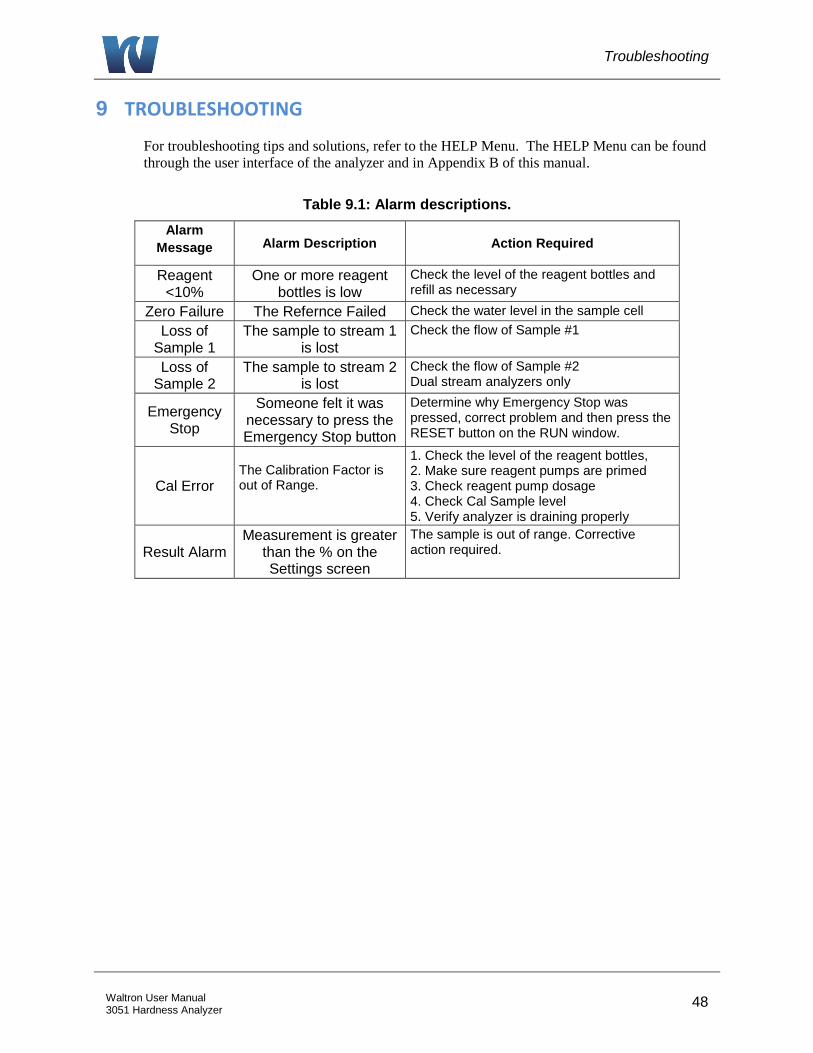
Troubleshooting
48 Waltron User Manual 3051 Hardness Analyzer
9 TROUBLESHOOTING
For troubleshooting tips and solutions, refer to the HELP Menu. The HELP Menu can be found
through the user interface of the analyzer and in Appendix B of this manual.
Table 9.1: Alarm descriptions.
Alarm
Message Alarm Description Action Required
Reagent <10%
One or more reagent bottles is low
Check the level of the reagent bottles and refill as necessary
Zero Failure The Refernce Failed Check the water level in the sample cell
Loss of Sample 1
The sample to stream 1 is lost
Check the flow of Sample #1
Loss of Sample 2
The sample to stream 2 is lost
Check the flow of Sample #2 Dual stream analyzers only
Emergency Stop
Someone felt it was necessary to press the Emergency Stop button
Determine why Emergency Stop was pressed, correct problem and then press the RESET button on the RUN window.
Cal Error The Calibration Factor is out of Range.
1. Check the level of the reagent bottles, 2. Make sure reagent pumps are primed 3. Check reagent pump dosage 4. Check Cal Sample level 5. Verify analyzer is draining properly
Result Alarm Measurement is greater
than the % on the Settings screen
The sample is out of range. Corrective action required.
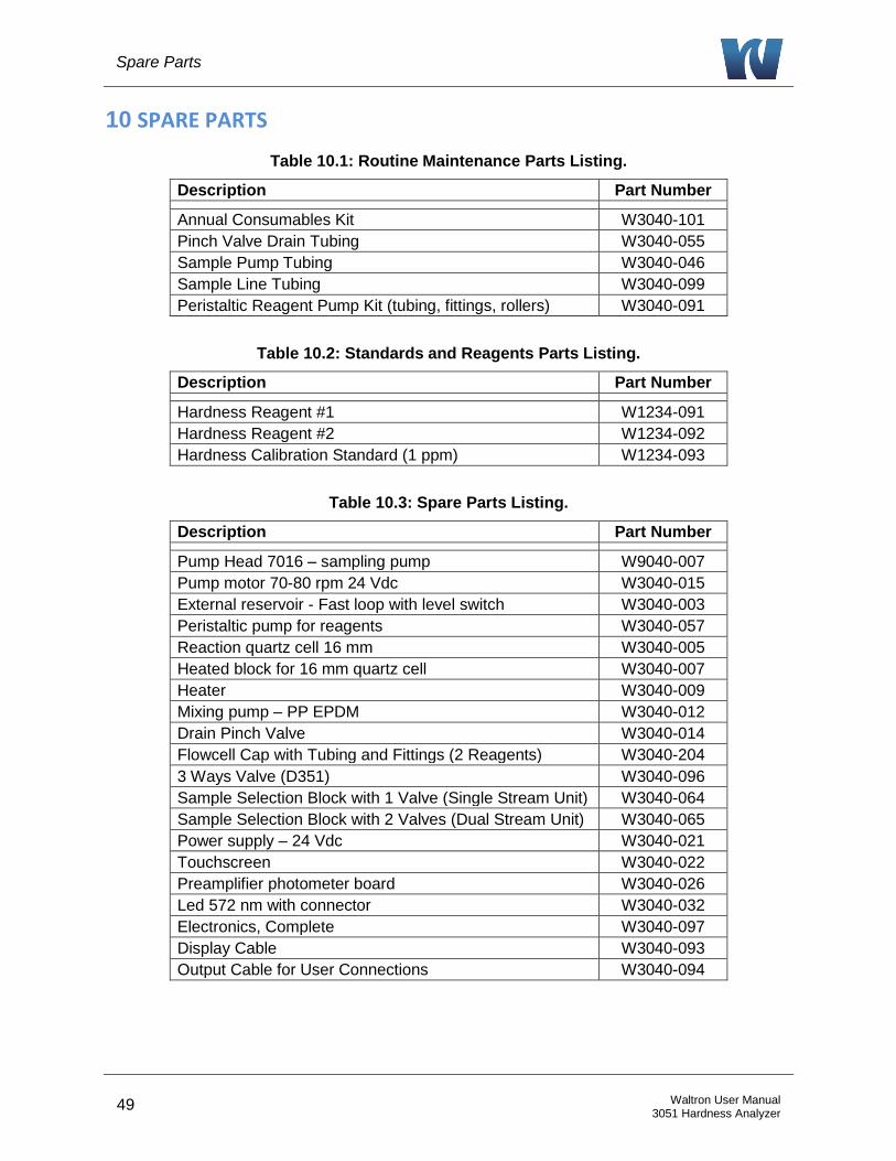
Spare Parts
49 Waltron User Manual 3051 Hardness Analyzer
10 SPARE PARTS
Table 10.1: Routine Maintenance Parts Listing.
Description Part Number
Annual Consumables Kit W3040-101
Pinch Valve Drain Tubing W3040-055
Sample Pump Tubing W3040-046
Sample Line Tubing W3040-099
Peristaltic Reagent Pump Kit (tubing, fittings, rollers) W3040-091
Table 10.2: Standards and Reagents Parts Listing.
Description Part Number
Hardness Reagent #1 W1234-091
Hardness Reagent #2 W1234-092
Hardness Calibration Standard (1 ppm) W1234-093
Table 10.3: Spare Parts Listing.
Description Part Number
Pump Head 7016 – sampling pump W9040-007
Pump motor 70-80 rpm 24 Vdc W3040-015
External reservoir - Fast loop with level switch W3040-003
Peristaltic pump for reagents W3040-057
Reaction quartz cell 16 mm W3040-005
Heated block for 16 mm quartz cell W3040-007
Heater W3040-009
Mixing pump – PP EPDM W3040-012
Drain Pinch Valve W3040-014
Flowcell Cap with Tubing and Fittings (2 Reagents) W3040-204
3 Ways Valve (D351) W3040-096
Sample Selection Block with 1 Valve (Single Stream Unit) W3040-064
Sample Selection Block with 2 Valves (Dual Stream Unit) W3040-065
Power supply – 24 Vdc W3040-021
Touchscreen W3040-022
Preamplifier photometer board W3040-026
Led 572 nm with connector W3040-032
Electronics, Complete W3040-097
Display Cable W3040-093
Output Cable for User Connections W3040-094
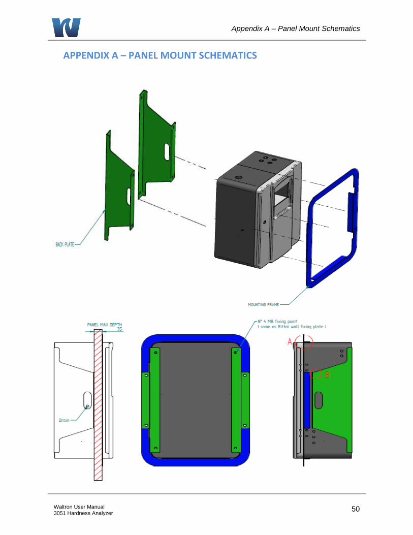
Appendix A – Panel Mount Schematics
50 Waltron User Manual 3051 Hardness Analyzer
APPENDIX A – PANEL MOUNT SCHEMATICS

Appendix A – Panel Mount Schematics
51 Waltron User Manual 3051 Hardness Analyzer

Appendix B – Help Menu
52 Waltron User Manual 3051 Hardness Analyzer
APPENDIX B – HELP MENU

Appendix B – Help Menu
53 Waltron User Manual 3051 Hardness Analyzer
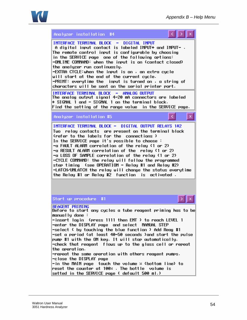
Appendix B – Help Menu
54 Waltron User Manual 3051 Hardness Analyzer
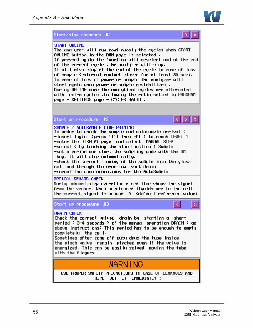
Appendix B – Help Menu
55 Waltron User Manual 3051 Hardness Analyzer
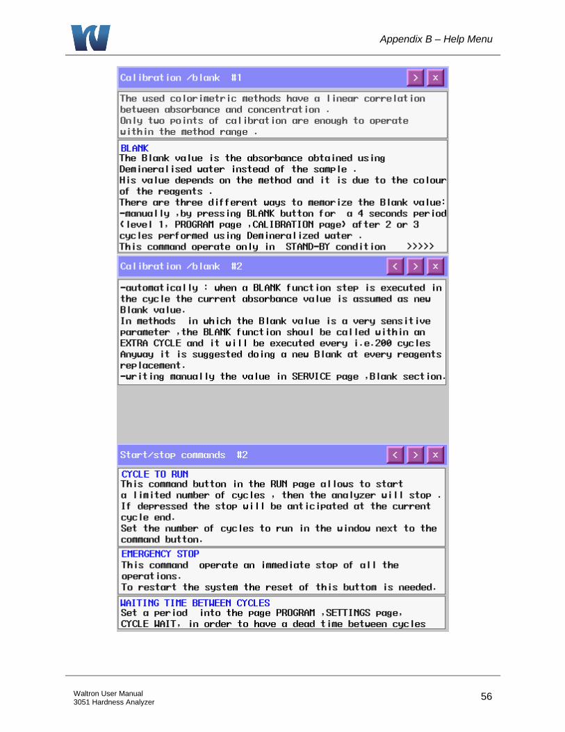
Appendix B – Help Menu
56 Waltron User Manual 3051 Hardness Analyzer
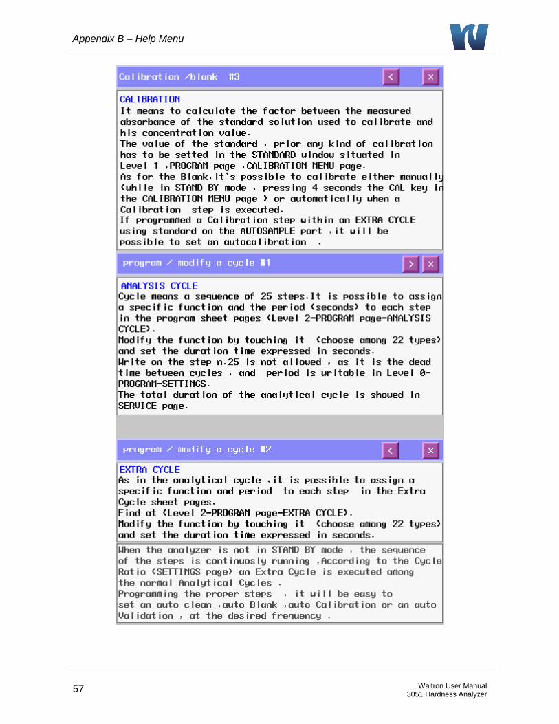
Appendix B – Help Menu
57 Waltron User Manual 3051 Hardness Analyzer

Appendix B – Help Menu
58 Waltron User Manual 3051 Hardness Analyzer

Appendix B – Help Menu
59 Waltron User Manual 3051 Hardness Analyzer
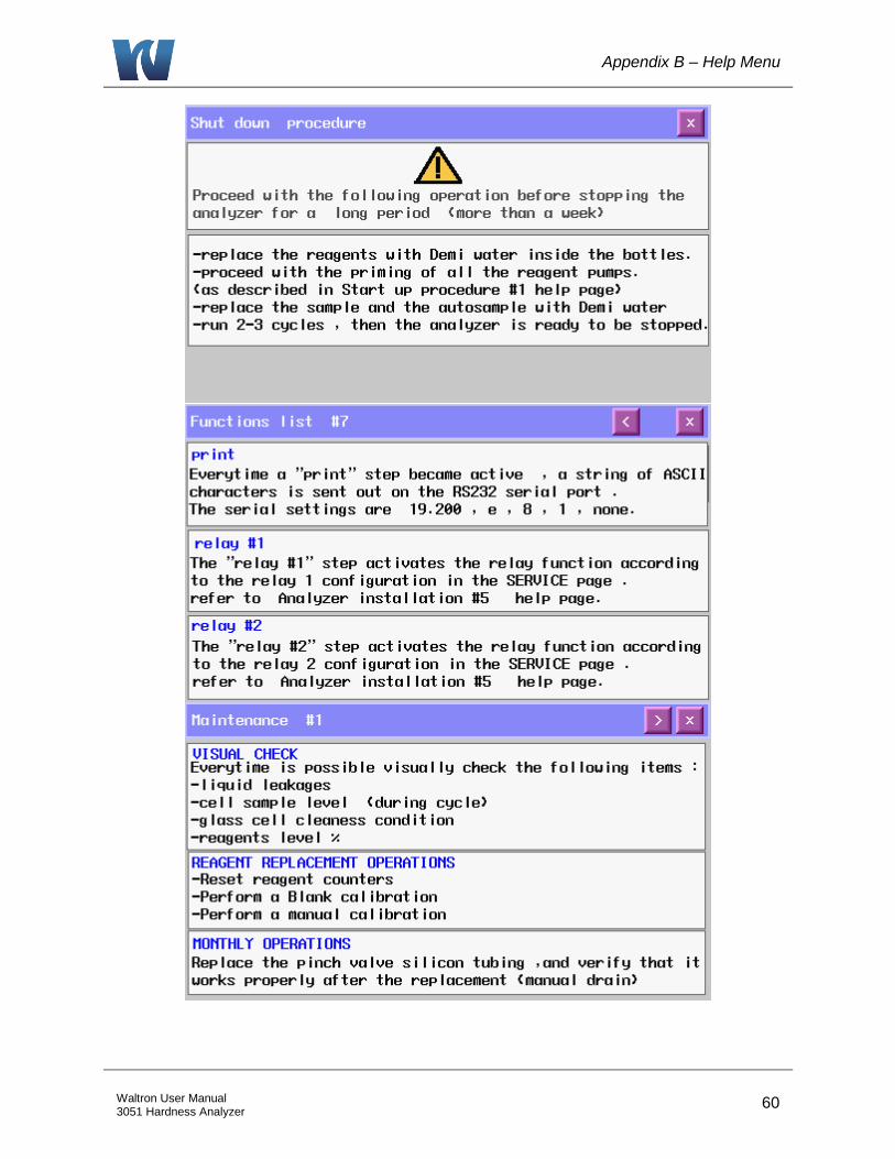
Appendix B – Help Menu
60 Waltron User Manual 3051 Hardness Analyzer
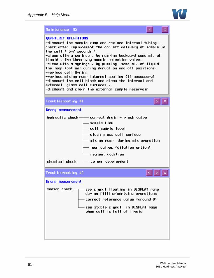
Appendix B – Help Menu
61 Waltron User Manual 3051 Hardness Analyzer
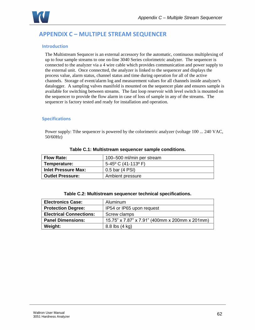
Appendix C – Multiple Stream Sequencer
62 Waltron User Manual 3051 Hardness Analyzer
APPENDIX C – MULTIPLE STREAM SEQUENCER
Introduction
The Multistream Sequncer is an external accessory for the automatic, continuous multiplexing of
up to four sample streams to one on-line 3040 Series colorimetric analyzer. The sequencer is
connected to the analyzer via a 4 wire cable which provides communication and power supply to
the external unit. Once connectted, the analyzer is linked to the sequencer and displays the
process value, alarm status, channel status and time during operation for all of the active
channels. Storage of event/alarm log and measurement values for all channels inside analyzer's
datalogger. A sampling valves manifold is mounted on the sequencer plate and ensures sample is
available for switching between streams. The fast loop reservoir with level switch is mounted on
the sequencer to provide the flow alarm in case of loss of sample in any of the streams. The
sequencer is factory tested and ready for installation and operation.
Specifications
Power supply: Tthe sequencer is powered by the colorimetric analyzer (voltage 100 ... 240 VAC,
50/60Hz)
Table C.1: Multistream sequencer sample conditions.
Flow Rate: 100–500 ml/min per stream
Temperature: 5-45º C (41-113º F)
Inlet Pressure Max: 0.5 bar (4 PSI)
Outlet Pressure: Ambient pressure
Table C.2: Multistream sequencer technical specifications.
Electronics Case: Aluminum
Protection Degree: IP54 or IP65 upon request
Electrical Connections: Screw clamps
Panel Dimensions: 15.75” x 7.87” x 7.91” (400mm x 200mm x 201mm)
Weight: 8.8 lbs (4 kg)
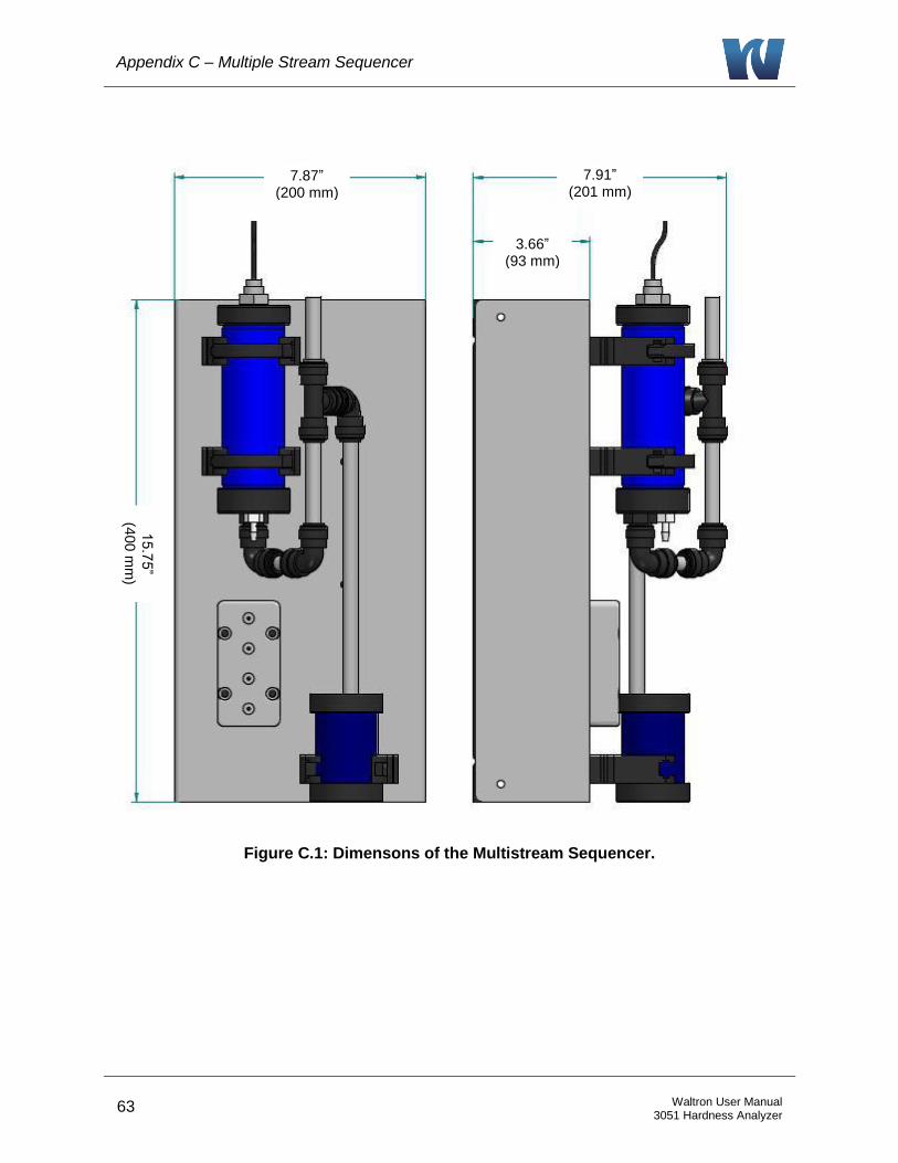
Appendix C – Multiple Stream Sequencer
63 Waltron User Manual 3051 Hardness Analyzer
Figure C.1: Dimensons of the Multistream Sequencer.
15.7
5”
(400 m
m)
7.87” (200 mm)
7.91” (201 mm)
3.66” (93 mm)
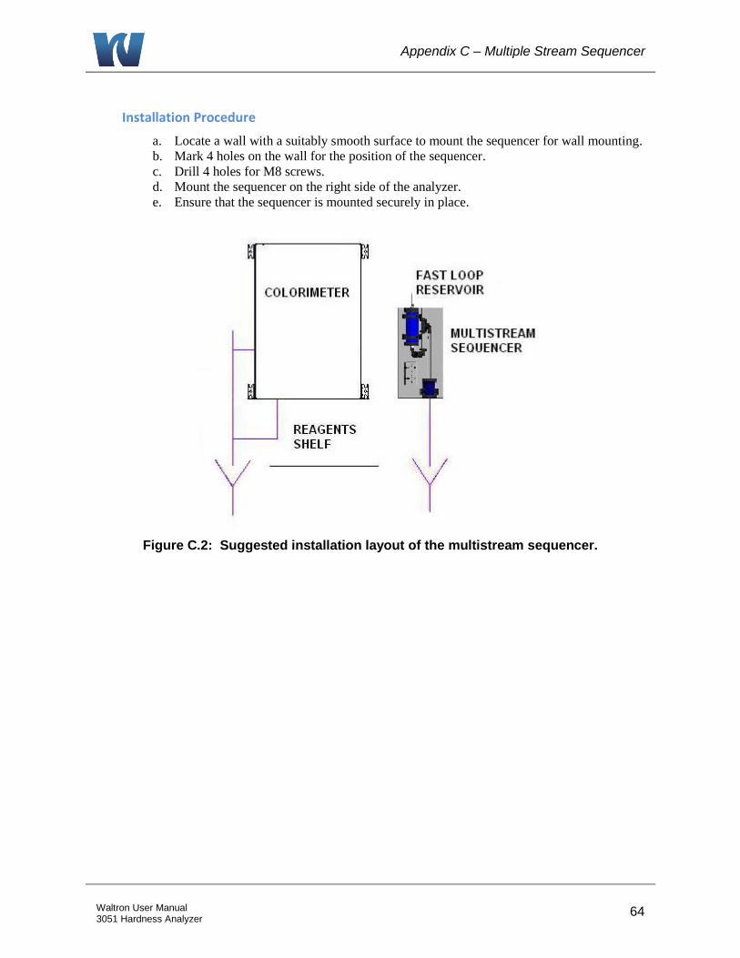
Appendix C – Multiple Stream Sequencer
64 Waltron User Manual 3051 Hardness Analyzer
Installation Procedure
a. Locate a wall with a suitably smooth surface to mount the sequencer for wall mounting.
b. Mark 4 holes on the wall for the position of the sequencer.
c. Drill 4 holes for M8 screws.
d. Mount the sequencer on the right side of the analyzer.
e. Ensure that the sequencer is mounted securely in place.
Figure C.2: Suggested installation layout of the multistream sequencer.
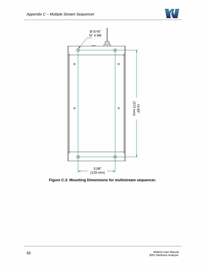
Appendix C – Multiple Stream Sequencer
65 Waltron User Manual 3051 Hardness Analyzer
Figure C.3: Mounting Dimensions for multistream sequencer.
Ø 5/16” N° 4 M8
5.08” (129 mm)
14.6
5”
(372 m
m)
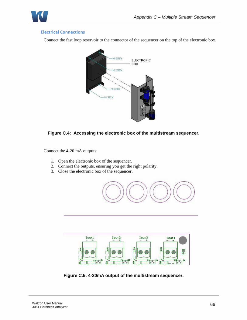
Appendix C – Multiple Stream Sequencer
66 Waltron User Manual 3051 Hardness Analyzer
Electrical Connections
Connect the fast loop reservoir to the connector of the sequencer on the top of the electronic box.
Figure C.4: Accessing the electronic box of the multistream sequencer.
Connect the 4-20 mA outputs:
1. Open the electronic box of the sequencer.
2. Connect the outputs, ensuring you get the right polarity.
3. Close the electronic box of the sequencer.
Figure C.5: 4-20mA output of the multistream sequencer.
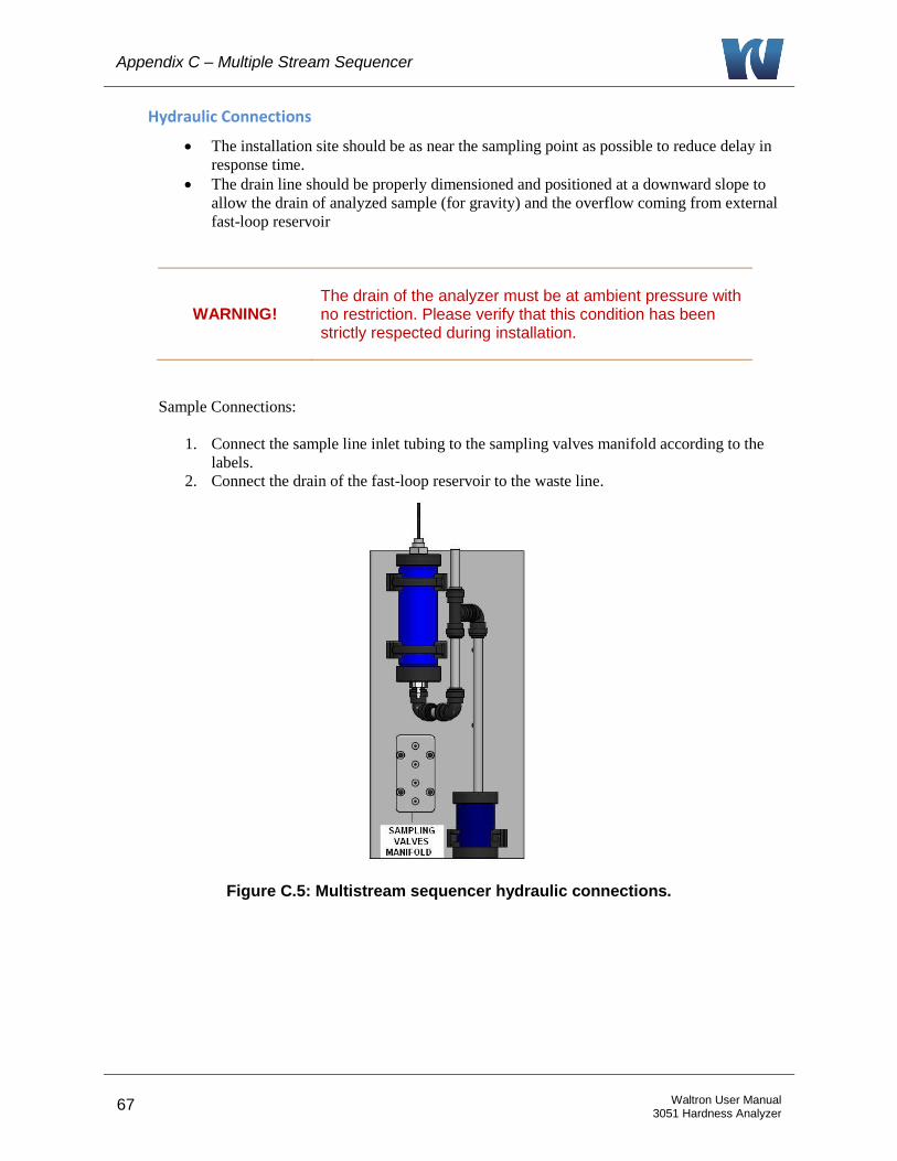
Appendix C – Multiple Stream Sequencer
67 Waltron User Manual 3051 Hardness Analyzer
Hydraulic Connections
The installation site should be as near the sampling point as possible to reduce delay in
response time.
The drain line should be properly dimensioned and positioned at a downward slope to
allow the drain of analyzed sample (for gravity) and the overflow coming from external
fast-loop reservoir
WARNING! The drain of the analyzer must be at ambient pressure with no restriction. Please verify that this condition has been strictly respected during installation.
Sample Connections:
1. Connect the sample line inlet tubing to the sampling valves manifold according to the
labels.
2. Connect the drain of the fast-loop reservoir to the waste line.
Figure C.5: Multistream sequencer hydraulic connections.
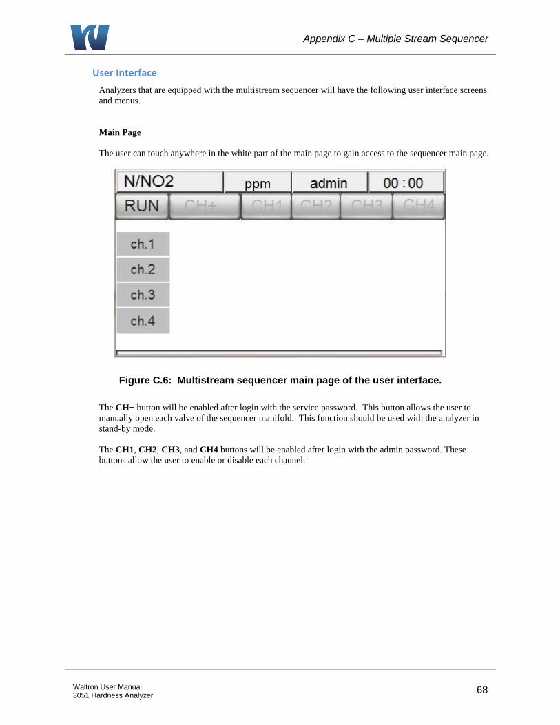
Appendix C – Multiple Stream Sequencer
68 Waltron User Manual 3051 Hardness Analyzer
User Interface
Analyzers that are equipped with the multistream sequencer will have the following user interface screens
and menus.
Main Page
The user can touch anywhere in the white part of the main page to gain access to the sequencer main page.
Figure C.6: Multistream sequencer main page of the user interface.
The CH+ button will be enabled after login with the service password. This button allows the user to
manually open each valve of the sequencer manifold. This function should be used with the analyzer in
stand-by mode.
The CH1, CH2, CH3, and CH4 buttons will be enabled after login with the admin password. These
buttons allow the user to enable or disable each channel.
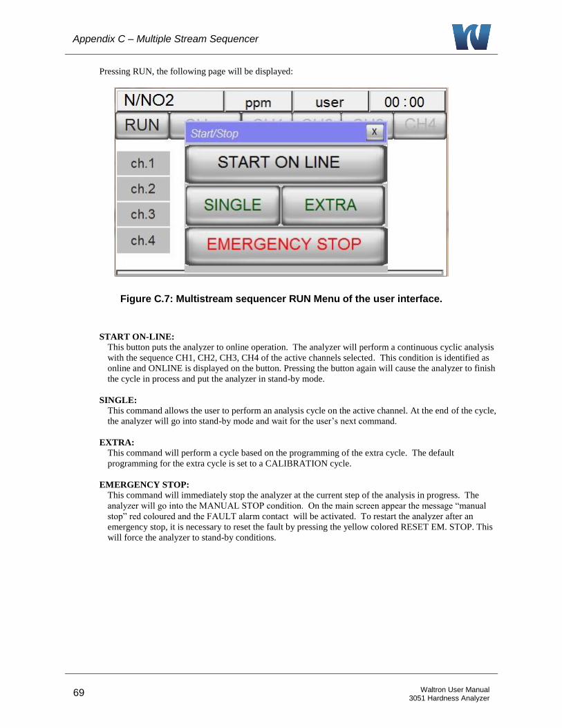
Appendix C – Multiple Stream Sequencer
69 Waltron User Manual 3051 Hardness Analyzer
Pressing RUN, the following page will be displayed:
Figure C.7: Multistream sequencer RUN Menu of the user interface.
START ON-LINE: This button puts the analyzer to online operation. The analyzer will perform a continuous cyclic analysis
with the sequence CH1, CH2, CH3, CH4 of the active channels selected. This condition is identified as
online and ONLINE is displayed on the button. Pressing the button again will cause the analyzer to finish
the cycle in process and put the analyzer in stand-by mode.
SINGLE:
This command allows the user to perform an analysis cycle on the active channel. At the end of the cycle,
the analyzer will go into stand-by mode and wait for the user’s next command.
EXTRA:
This command will perform a cycle based on the programming of the extra cycle. The default
programming for the extra cycle is set to a CALIBRATION cycle.
EMERGENCY STOP: This command will immediately stop the analyzer at the current step of the analysis in progress. The
analyzer will go into the MANUAL STOP condition. On the main screen appear the message “manual
stop” red coloured and the FAULT alarm contact will be activated. To restart the analyzer after an
emergency stop, it is necessary to reset the fault by pressing the yellow colored RESET EM. STOP. This
will force the analyzer to stand-by conditions.