Embed Size (px)
DESCRIPTION
TN-TS
Citation preview

User Manual 3000 systems
TN/TS/TX Version: 2.0.2

User Manual TN-TS 3000 Rev. 2.0.2
User Manual 3000 systems V2.0.doc Page 2 of 169
Disclaimer Save to the extent permitted by law, the Customer hereby undertakes not to alter or modify the whole or any part of the software incorporated in the Products in any way whatever nor permit the whole or any part of the software to be combined with or become incorporated in any other programs nor decompile disassemble or reverse engineer the same nor attempt to do any other such things. In no event shall [Thermo Fisher Scientific] have any obligation to repair or replace in accordance with any warranties given with the Product in whole or in part, as the result of
• Accident, disaster or event of force majeure • Customers misuse, fault or negligence by or on the Customers behalf • Use of the software in a manner for which it was not designed • Causes external to the software such as, but not limited to, power failure or electrical power
surges • Use of the software in combination with equipment or software not supplied by Thermo Fisher
Scientific or with which it is incompatible.
The warranty shall not apply to any software which the Customers alters or modifies. Thermo Fisher Scientific does not warrant that the software is error-free, will accomplish any particular result or is fit for any particular purpose of or intended use by the Customer and it is for the Customer to satisfy yourself that the software is so fit. The photographs used in this manual can differ from the actual apparatus and set-up’s. All photographs, drawings and diagrams are for illustrative purposes only.

User Manual TN-TS 3000 Rev. 2.0.2
User Manual 3000 systems V2.0.doc Page 3 of 169
Copyright The content of this manual is protected by copyright. All efforts have been made to ensure the accuracy of the contents of this manual. However should any errors be detected Thermo Fisher Scientific would greatly appreciate being informed of them The above notwithstanding Thermo Fisher Scientific can assume no responsibility for any errors in this manual or their consequences. For more information, check our website at www.thermo.com Any use of this manual other than, intended by the producer, is prohibited without the prior written permission of Thermo Fisher Scientific © 2000-2007, Copyright reserved by Thermo Fisher Scientific Delft, The Netherlands

User Manual TN-TS 3000 Rev. 2.0.2
User Manual 3000 systems V2.0.doc Page 4 of 169
Content
1. GENERAL INFORMATION ....................................................................................... 10
1.1. OPERATING MANUAL................................................................................................ 10 1.2. PICTOGRAMS ............................................................................................................. 11 1.3. SERVICE AND MAINTENANCE.................................................................................... 12
2. GENERAL SAFETY INSTRUCTIONS...................................................................... 13
2.1. SAFETY MARKS ON THE EQUIPMENT ......................................................................... 13 2.2. SAFETY RULES FOR THE OPERATOR ........................................................................... 14
2.2.1. Rules applying to installation........................................................................... 14 2.2.2. Do’s and don’ts with the 3000 system.............................................................. 15
3. PRINCIPLE OF THE MEASUREMENT................................................................... 16
3.1. INTRODUCTION OF THE 3000 SYSTEM (TN-TS) ......................................................... 16 3.2. PRINCIPLE OF THE UV-FLUORESCENCE DETECTION................................................... 17 3.3. PRINCIPLE OF CHEMILUMINESCENSE DETECTION....................................................... 19 3.4. GENERAL FLOW-PATH 3000 SYSTEM TN-TS............................................................. 20 3.5. SAMPLE INTRODUCTION ............................................................................................ 21
3.5.1. The "Liquids Module" (solvents, gasses, light hydrocarbons)......................... 21 3.5.2. The "Liquids Module" (model “0019”) ........................................................... 22 3.5.3. The "Solids module" universal ......................................................................... 23 3.5.4. The "TN 3000 Solids module" .......................................................................... 24 The "Liquids Module Water" (Nitrogen according DIN) ............................................... 24 3.5.5. The "TN 3000 Liquids Module" for light hydrocarbons .................................. 25
3.6. FURNACE................................................................................................................... 25 3.6.1. Standard furnace tube ...................................................................................... 25 3.6.2. Turbo tube ........................................................................................................ 26
3.7. CONDITIONING .......................................................................................................... 27 3.7.1. Drying............................................................................................................... 27 3.7.2. C.F.I.S. (patented) ............................................................................................ 27 3.7.3. Molybdenum converter..................................................................................... 28
3.8. SULFUR DETECTOR .................................................................................................... 28 3.9. PHOTO MULTIPLIER TUBE......................................................................................... 29 3.10. DETECTOR FOR NITROGEN ........................................................................................ 30
4. INSTALLATION OF THE 3000 SYSTEM................................................................. 31
4.1. INTRODUCTION.......................................................................................................... 31 4.2. 3000 SYSTEM, EXTERNAL CONNECTIONS AND SPECIFICATIONS ................................. 31
4.2.1. Power connections ........................................................................................... 31 4.2.2. Communication connections ............................................................................ 32 4.2.3. Gasses: connections and specifications ........................................................... 33 4.2.4. 3000 system glassware connections................................................................. 34 4.2.5. Sample introduction modules ........................................................................... 34
4.2.5.1. The "Liquids module" .............................................................................. 34 4.2.5.2. The "Solids module" ................................................................................ 34 4.2.5.3. The "Liquids module Water" ................................................................... 35
4.2.6. Furnace tube .................................................................................................... 35
User Manual TN-TS 3000 Rev. 2.0.2
User Manual 3000 systems V2.0.doc Page 5 of 169
4.2.7. Outlet connection (TN)..................................................................................... 36 4.3. PERMA PURE.............................................................................................................. 36 4.4. GLASS-FIBER FILTER ................................................................................................. 37 4.5. GAS CONNECTION TN-TS, SEPARATE AND SIMULTANEOUSLY .................................. 37
4.5.1. Separate analyses............................................................................................. 37 4.5.2. Simultaneous analyses ..................................................................................... 37 4.5.3. Connection furnace outlet TS only ................................................................... 38 4.5.4. Mode selection gas flow: separate or simultaneous ........................................ 40
4.6. UV-F DETECTOR MODULE......................................................................................... 41 4.6.1. Connections and settings on UV-F detector .................................................... 42
5. OPERATING THE 3000 SYSTEM.............................................................................. 44
5.1. 3000 SYSTEM START UP ............................................................................................ 44 5.2. PREPARATION OF SOLUTIONS .................................................................................... 44
5.2.1. Sulfur standards ............................................................................................... 44 5.2.1.1. Dibenzothiophene stock solution (sulfur determination)........................ 44 5.2.1.2. Dibenzothiophene standard solution (100 mg S/L) ................................ 44 5.2.1.3. Dibenzothiophene standard solution (50 mg S/L) .................................. 44 5.2.1.4. Dibenzothiophene test solution (10 mg S/L) .......................................... 45 5.2.1.5. Dibenzothiophene test solution (5 mg S/L) ............................................ 45 5.2.1.6. Dibenzothiophene test solution (1 mg S/L) ............................................ 45
5.2.2. Nitrogen standards (petro)............................................................................... 45 5.2.2.1. Carbazole stock-solution (nitrogen determination).................................. 45 5.2.2.2. Carbazole standard solution ..................................................................... 45 5.2.2.3. Benzonitrile stock-solution ...................................................................... 45 5.2.2.4. Benzonitrile standard solution.................................................................. 45
5.2.3. Nitrogen standards (water) .............................................................................. 46 5.2.3.1. Preparation of the Nitrate stock................................................................ 46 5.2.3.2. Preparation of the Ammonia stock........................................................... 47 5.2.3.3. Preparation of the Ammonia-Nitrate mix stock ....................................... 47 5.2.3.4. Preparation of the Glycine stock .............................................................. 48
5.2.4. Furnace tube and permapure connection ........................................................ 48 5.2.5. Module connection ........................................................................................... 48 5.2.6. Powering the system......................................................................................... 49 5.2.7. Adjust the gas flow (Manual) ........................................................................... 49 5.2.8. Gas leakage test basic 3000 system ................................................................. 51 5.2.9. Gas leakage test UV detection module............................................................. 52
5.3. 3000 SYSTEM NORMAL OPERATION ........................................................................... 53 5.3.1. Visible inspection of glassware........................................................................ 53 5.3.2. Glassware maintenance ................................................................................... 53
5.3.2.1. Furnace tube ............................................................................................. 53 5.3.2.2. SOLIDS glassware ................................................................................... 54
5.3.3. Introduction module ......................................................................................... 54 5.3.3.1. Solids Module .......................................................................................... 54 5.3.3.2. Liquids Module ........................................................................................ 54 5.3.3.3. TN water module...................................................................................... 54
5.3.4. Standard software settings ............................................................................... 54 5.3.5. Running analysis .............................................................................................. 55

User Manual TN-TS 3000 Rev. 2.0.2
User Manual 3000 systems V2.0.doc Page 6 of 169
5.3.5.1. Starting ThEuS™...................................................................................... 55 5.3.5.2. Creating a calibration ............................................................................... 58
5.4. QUICK PERFORMANCE CHECK TN/TS MODE.............................................................. 59 5.4.1. TN mode test (setting is low range).................................................................. 59 5.4.2. TS-UV mode test (setting is mid-range) ........................................................... 59
5.5. 3000 SYSTEM STANDBY MODE .................................................................................. 60 5.6. 3000 SYSTEM SHUT DOWN......................................................................................... 60
6. TN WATER .................................................................................................................... 61
6.1. INTRODUCTION.......................................................................................................... 61 6.2. SPECIFICATIONS ........................................................................................................ 62
6.2.1. Standardized methods ...................................................................................... 62 6.2.2. Test results of the TN-3000 water .................................................................... 62 6.2.3. Summary/conclusion ........................................................................................ 63
6.3. MAINTENANCE OF THE GLASSWARE .......................................................................... 64 6.3.1. Boat and introduction module.......................................................................... 64 6.3.2. Outlining of the boat ........................................................................................ 65 6.3.3. Replacement of the Nickel sample cylinder ..................................................... 65 6.3.4. NeXYZ auto sampler......................................................................................... 66 6.3.5. Furnace tube and outlet ................................................................................... 66 6.3.6. Principle of the furnace outlet tube.................................................................. 68 6.3.7. Cold trap, tubing and filter .............................................................................. 69
6.4. SEVERAL REMARKS AND TIPS .................................................................................... 71 6.5. FREQUENT MAINTENANCE......................................................................................... 71 6.6. TROUBLE SHOOTING.................................................................................................. 72 6.7. FLOW DIAGRAM TN WATER ...................................................................................... 74
7. EXTERNAL SAMPLERS............................................................................................. 75
7.1. NEXYZ AUTOSAMPLER............................................................................................. 75 7.2. ECA1700 AOX COLUMN AUTOSAMPLER ................................................................. 75
7.2.1. Introduction-Description.................................................................................. 75 7.2.2. ECA-TOX method, step by step ........................................................................ 77 7.2.3. Installation ECA1700....................................................................................... 77 7.2.4. ECA1700, Mounting......................................................................................... 78 7.2.5. ECA1700, external connections ....................................................................... 81 7.2.6. ECA1700: System and software settings.......................................................... 82 7.2.7. Software settings ECA1700.............................................................................. 82
7.3. ESA2000 AOX AND SOLIDS AUTO SAMPLER............................................................ 84 7.3.1. Introduction-Description.................................................................................. 84 7.3.2. ESA-AOX batch method, step by step............................................................... 85 7.3.3. General solids method, step by step................................................................. 86 7.3.4. Installation of the ESA2000 ............................................................................. 87 7.3.5. ESA2000, Mounting ......................................................................................... 87 7.3.6. ESA2000 hardware alignment procedure ........................................................ 90 7.3.7. ESA2000 external connections......................................................................... 92 7.3.8. ESA2000: System and software settings .......................................................... 93 7.3.9. Software settings ESA2000 .............................................................................. 94 7.3.10. ESA Boat program and related settings........................................................... 96

User Manual TN-TS 3000 Rev. 2.0.2
User Manual 3000 systems V2.0.doc Page 7 of 169
8. COULOMETRIC ANALYSIS ON THE 3000 SYSTEM (OPTIONAL).................. 98
8.1. INTRODUCTION 3000 SYSTEM IN HALOGEN/SULFUR MODE.................................... 98 8.2. PRINCIPLE OF THE MEASUREMENTS ........................................................................... 99 8.3. SAMPLE INTRODUCTION ............................................................................................ 99
8.3.1. Manual sampling modules ............................................................................... 99 8.3.1.1. AOX module .......................................................................................... 100 8.3.1.2. POX module ........................................................................................... 100 8.3.1.3. Solids Module ........................................................................................ 100 8.3.1.4. Liquid Module........................................................................................ 101
8.3.2. Auto sampling................................................................................................. 102 8.4. FURNACE................................................................................................................. 102 8.5. GAS CONDITIONING ................................................................................................. 102 8.6. DETECTOR, COULOMETRIC TITRATION .................................................................... 102
8.6.1. Halide analysis, principle .............................................................................. 103 8.6.1.1. Halide analysis, titration cell.................................................................. 105 8.6.1.2. Halide analysis, circuit diagram............................................................. 106
8.6.2. Sulfur analysis, principle ............................................................................... 107 8.6.2.1. Sulfur analysis, titration cell .................................................................. 108 8.6.2.2. Sulfur analysis, circuit diagram.............................................................. 109
8.7. DATA PROCESSING .................................................................................................. 110
9. INSTALLATION HALOGEN AND SULFUR OPTION (COULOMETRIC)...... 111
9.1.1. Glassware connections................................................................................... 111 9.1.2. Sample introduction module .......................................................................... 111
9.1.2.1. AOX module .......................................................................................... 111 9.1.2.2. POX module ........................................................................................... 112 9.1.2.3. Solids Module ........................................................................................ 112 9.1.2.4. Liquid Module........................................................................................ 112
9.1.3. Furnace tube .................................................................................................. 112 9.1.4. Connection tube furnace scrubber ................................................................. 112 9.1.5. Installation sulfuric acid scrubber ................................................................. 112 9.1.6. Sulfuric acid scrubber connected................................................................... 113 Figure: sulfuric acid scrubber assembly........................................................................ 113 9.1.7. NOx-scrubber.................................................................................................. 113 9.1.8. Detector, titration cell .................................................................................... 114 9.1.9. Cell compartment and cooling ....................................................................... 115
10. OPERATING THE 3000 SYSTEM IN TX/TS MODE ........................................ 116
10.1. 3000 SYSTEM TX/TS MODE STARTING UP........................................................ 116 10.1.1. Preparation of reagents ................................................................................. 116
10.1.1.1. Sulfuric acid solution ............................................................................. 116 10.1.1.2. Halide electrolytic solution .................................................................... 116 10.1.1.3. Sulfur electrolytic solution..................................................................... 116
10.1.2. AOX reagents ................................................................................................. 117 10.1.2.1. Nitrate stock solution ............................................................................. 117 10.1.2.2. Nitrate wash solution.............................................................................. 117 10.1.2.3. p-Chlorophenol stock solution (200 mg Cl/L) ....................................... 117 10.1.2.4. p-Chlorophenol standard solution (1 mg Cl/L) ...................................... 117

User Manual TN-TS 3000 Rev. 2.0.2
User Manual 3000 systems V2.0.doc Page 8 of 169
10.1.2.5. p-Chlorophenol test solution (100 μg Cl/L)........................................... 117 10.1.3. POX reagents ................................................................................................. 117
10.1.3.1. Dichloromethane stock solution (1000mg Cl/L).................................... 117 10.1.3.2. Dichloromethane standard solution (100mg Cl/L) ................................ 117 10.1.3.3. Dichloromethane test solution (100 μg Cl/L) ........................................ 117
10.1.4. TX/EOX reagents............................................................................................ 118 10.1.4.1. Aldrin stock solution (1000 mg Cl/L) .................................................... 118 10.1.4.2. Aldrin standard solution (100 mg Cl/L)................................................. 118 10.1.4.3. Aldrin test solution (10 mg Cl/L)........................................................... 118
10.1.5. TS/EOS reagents ............................................................................................ 118 10.1.5.1. Diphenylsulfide stock solution (1000mg S/L) ....................................... 118 10.1.5.2. Diphenylsulfide standard solution (100mg S/L) .................................... 118 10.1.5.3. Diphenylsulfide test solution (10mg S/L) .............................................. 118
10.1.6. Preparation of samples .................................................................................. 119 10.1.6.1. AOX sample preparation........................................................................ 119 10.1.6.2. POX sample preparation ........................................................................ 121 10.1.6.3. TOX sample preparation ........................................................................ 121 10.1.6.4. EOX sample preparation ........................................................................ 122
10.1.7. Adjusting gas flows ........................................................................................ 124 10.1.8. Filling the scrubber........................................................................................ 124
10.1.8.1. Sulfuric acid scrubber ............................................................................ 124 10.1.8.2. NOx-scrubber.......................................................................................... 125
10.1.9. Powering the system....................................................................................... 125 10.1.10. Installing a selected Module ...................................................................... 125 10.1.11. Titration cell (chloride).............................................................................. 126 10.1.12. Titration cell (sulfur).................................................................................. 127 10.1.13. Gas leakage test coulometric configuration .............................................. 128
10.2. 3000 SYSTEM NORMAL OPERATION.................................................................. 130 10.2.1. Visible inspection of glassware...................................................................... 130 10.2.2. Glassware maintenance ................................................................................. 130
10.2.2.1. Scrubber ................................................................................................. 130 10.2.2.2. Furnace tube ........................................................................................... 131 10.2.2.3. Liquids module....................................................................................... 131 10.2.2.4. AOX glassware ...................................................................................... 131 10.2.2.5. POX glassware ....................................................................................... 132 10.2.2.6. Solids glassware ..................................................................................... 132
10.2.3. Introduction module ....................................................................................... 132 10.2.3.1. Solids Module ........................................................................................ 132 10.2.3.2. Liquids Module ...................................................................................... 132 10.2.3.3. AOX Module.......................................................................................... 132 10.2.3.4. POX Module .......................................................................................... 132
10.2.4. Standard setpoints .......................................................................................... 133 10.3. 3000 SYSTEM STANDBY MODE ......................................................................... 133 10.4. 3000 SYSTEM SHUT DOWN................................................................................ 134
11. RUNNING ANALYSIS TX/TS MODE (COULOMETRIC)............................... 135
11.1. MANUAL ANALYSIS IN GENERAL ......................................................................... 135 11.2. MANUAL ANALYSIS USING SPECIFIC MODULES/METHODS.................................... 135

User Manual TN-TS 3000 Rev. 2.0.2
User Manual 3000 systems V2.0.doc Page 9 of 169
11.2.1.1. Manual introduction POX ...................................................................... 135 11.2.1.2. Manual introduction AOX ..................................................................... 136 11.2.1.3. Manual introduction Solids, water and heavy hydrocarbons ................. 137 11.2.1.4. Manual injection EOX and “light hydrocarbons”.................................. 138
11.3. AUTOMATIC ANALYSIS IN GENERAL .................................................................... 138 11.4. AUTOMATIC ANALYSIS USING SPECIFIC MODULES/METHODS............................... 139
11.4.1.1. Automatic analysis AOX ....................................................................... 139 11.4.2. Automatic introduction Solids, water and “heavy” hydrocarbons................ 139
11.4.2.1. Automatic injection EOX and “light hydrocarbons” ............................. 139
12. TROUBLESHOOTING NITROGEN-SULFUR UV MODE .............................. 140
13. TROUBLESHOOTING COULOMETRIC OPTION.......................................... 142
14. CONSUMABLES AND SPARE PARTS ............................................................... 146
15. APPENDIX I : SETTINGS .................................................................................... 150
16. APPENDIX II INTERNATIONAL CHEMICAL SAFETY CARDS .............. 151
17. APPENDIX III QUICK REFERENCE START ANALYSIS -STANDBY........ 166
18. APPENDIX IV CONVERSION TABLE: MANUAL ROTAMETERS TO DIGITAL MASSFLOW METERS .................................................................................... 167
19. APPENDIX V TECHNICAL SPECIFICATIONS .............................................. 168

User Manual TN-TS 3000 Rev. 2.0.2
User Manual 3000 systems V2.0.doc Page 10 of 169
1. GENERAL INFORMATION
1.1. Operating Manual
This operating manual has been written with the user of the 3000 system in mind. For this reason the manual mainly gives instructions detailing operation of the apparatus and does not give detailed directions for the maintenance or repair of the apparatus. The organization making use of the 3000 system must ensure itself that the operator is qualified to use an instrument of this sort and is capable of following the recommendations for its use. The operator should closely follow the instructions contained in this operating manual in order to ensure the proper operation of the instrument. This manual makes use of special signs and pictograms in order to highlight remarks and instructions, which require special attention. These signs and pictograms are listed in section 1.2 of this chapter. Chapter 2 – “General Safety Instructions" details the safety pictograms appearing on the outside of / and inside the apparatus. All directions relating to these pictograms must be complied with at all times. Should you encounter problems or have questions, which are not discussed in this manual, please do not hesitate to get in touch with your Thermo Fisher Scientific supplier.
Voltaweg 22 2627 BC, Delft The Netherlands Tel.: +31 (0)15 2571314 Fax.:+31 (0)15 2572297
EMail: [email protected] (for technical questions and remarks)
[email protected] (for questions and remarks about the user’s guide)
Web: http://www.thermo.com

User Manual TN-TS 3000 Rev. 2.0.2
User Manual 3000 systems V2.0.doc Page 11 of 169
1.2. Pictograms
The following pictograms are used to highlight the information contained in the text of this manual.
Special Attention Text preceded by this sign should be read with special care.
Warning Instructions preceded by this sign must be complied with exactly. Failure to do so may result in damage to the equipment or physical injury. Furthermore, the measurement procedure may be disturbed.
Electrical Hazard Instructions preceded by this sign must be complied with exactly. Failure to do so may result in physical injury.
Heat Instructions preceded by this sign must be complied with exactly. Failure to do so may result in physical injury.

User Manual TN-TS 3000 Rev. 2.0.2
User Manual 3000 systems V2.0.doc Page 12 of 169
1.3. Service and Maintenance
Maintenance should only be carried out by persons specially trained by Thermo Fisher Scientific employees for this purpose, with the sole exception of the routine maintenance. The operator should carry out the latter. We recommend submitting the 3000 system for technical maintenance by the suppliers specialists, at least once a year, in order to ensure its continued precision operation.

User Manual TN-TS 3000 Rev. 2.0.2
User Manual 3000 systems V2.0.doc Page 13 of 169
2. GENERAL SAFETY INSTRUCTIONS The 3000 system has been designed and manufactured in accordance with the following standard. - ISO 3864 Safety colors and safety signs. Before using the 3000 system carefully read through this operating manual. It is essential that the persons operating the apparatus or who come into direct contact with it are fully informed of the nature and existence of all possible hazardous areas in and around the apparatus.
2.1. Safety Marks on the equipment
Thermo Fisher Scientific uses the following safety colors and signs on the analysis apparatus. These are based on the ISO 3864 international standards for safety colors and signs. These signs indicate those locations that require special attention and/or constitute a danger to personnel or the apparatus. The safety markings may be replaced or supplemented by explanatory texts. All personnel coming into either direct or indirect contact with the 3000 system should be fully acquainted with these international safety-markings. The signs and accompanying texts appearing on or inside the 3000 system are shown below.
THE FURNACE CAN ATTAIN VERY HIGH TEMPERATURES
THE OUTLET REACHES A TEMPERATURE OF 300°C. ALLOW THE OUTLET TO COOL BEFORE REMOVING.
HIGH VOLTAGE! DO NOT REMOVE COVER!

User Manual TN-TS 3000 Rev. 2.0.2
User Manual 3000 systems V2.0.doc Page 14 of 169
Precautions and/or conditions imposed by national laws or company safety procedures, applying to the space where the 3000 system is used must be respected unconditionally! Making these instructions known and ensuring compliance with them is a responsibility for the management of your organization. In case of doubt, consult your supervisor.
2.2. Safety rules for the operator
The general safety rules applicable to the apparatus are given below.
2.2.1. Rules applying to installation
The apparatus must be installed by duly qualified technicians or in accordance with the instructions provided by supplier. Please note the following requirements: • Provide a well ventilated space; • Avoid installation in a space where the apparatus is exposed to direct
sunlight and large fluctuations in temperature; • The satisfactory operation of the equipment is guaranteed when it is
installed in an environment with temperatures between 10 and 30°C and a relative humidity between 20 and 85%;
• Allow 20 cm of free space around the apparatus; • provide a firm, smooth and horizontal surface measuring at least 80 x
160 cm • Provide connections for supplies of oxygen (02) and argon (Ar)
/helium (He), pressure 1-3 Bar, 1/8" connector; • Make sure that there is a suitable electrical supply nearby, 115/230
V, 50/60 Hz, at least 3600 W; • Always connect the 3000 system directly to a grounded power point
using a 16 Amp. fused plug. In case of doubt consult an authorized installer;
• Never use adapter plugs. • Keep wires well clear from the furnace in- and outlet. • Never connect the 3000 system to other equipment that does not
comply to safety class II.
Warning An incorrectly grounded or ungrounded apparatus may cause electric shock.

User Manual TN-TS 3000 Rev. 2.0.2
User Manual 3000 systems V2.0.doc Page 15 of 169
2.2.2. Do’s and don’ts with the 3000 system • Refer to the manual in case of doubt about a procedure, prior to
start-up, running samples or shut-down. • Wear protective clothing, masks and spectacles in accordance with
the laboratory requirements for carrying out the measurements. • Make sure that the apparatus is grounded as specified. • The apparatus should be set up in such a way that it does not
constitute a danger to the user during the course of the work. • Make regular checks on the connecting cables and gas piping for
possible damage and leaks. • The apparatus may only be used for the purpose for which it is
intended and may be operated solely by qualified personnel. • Never place heavy objects on the 3000 system. • Never carry out any maintenance on the 3000 system, which is not
described in this manual. • Never remove any covers, doors or panels, which are fastened into
position by means of screws. • Keep all the analytical and other compartments provided with
opening flaps shut during the performance of analyses when this is so required.
• Always use original materials and accessories developed by Thermo Fisher Scientific. Unapproved materials and accessories may cause the malfunction of the apparatus or give rise to hazardous situations.
• The use of parts, which are not manufactured/approved by Thermo Fisher Scientific, could result into exclusion of warranty arrangements.
• In case of a malfunction that could endanger safety, turn off the apparatus immediately.
• Never sprinkle the housing with water or other liquids. To clean, wipe with a moist cloth.
• Never shut the ventilation openings and check them regularly if they are free from possible tissues and other items that could cause blockage.
• Never place combustible materials on top of the analyzer. (tissues, solvents, etc.)

User Manual TN-TS 3000 Rev. 2.0.2
User Manual 3000 systems V2.0.doc Page 16 of 169
3. PRINCIPLE OF THE MEASUREMENT
3.1. Introduction of the 3000 system (TN-TS)
For many years, Thermo Fisher Scientific is a high quality producer of analyzers used for the determination of the sulfur quantity in several kinds of samples. This reliable technique was and still is, based on coulometric detection by iodometric-titration. The use of a coulometric detection is still very reproducible with a low limit of detection. In practice it becomes more important every year to determine the amount of sulfur as well as the amount of nitrogen in the same types of samples. Until this moment, it was only possible to analyze both these elements on different systems, by performing two analyses. To determine both these elements simultaneously it is necessary to use a “dry” detection technique for the analyses of sulfur and combining two detectors in one analyzer. Thermo Fisher Scientific has developed a SO2 - UV fluorescence detector, which is designed to run separately or simultaneously with the Nitrogen analyzer TN3000 or as a stand-alone unit, attached to any 3000 system. The 3000 system is designed for fast and efficient analysis of total sulfur (S) and nitrogen (N2). The 3000 system supports the use of different modules, which are used for the introduction of various sample matrices into the furnace. (e.g. ASTM) The SO2 and NO produced by combustion, is led trough both detectors. SO2 is detected by the principal of fluorescence in combination with a Photo Multiplier Tube {P.M.T.}. NO is detected by chemiluminescense. Both analysis techniques are relative and make that calibration is required. The basic flow-path for the measurement of NO and SO2 is as follows:
Gas outlet
UV-Fluorescence detector
Permapure
Chemiluminescense detector

User Manual TN-TS 3000 Rev. 2.0.2
User Manual 3000 systems V2.0.doc Page 17 of 169
3.2. Principle of the UV-fluorescence detection The sample is introduced into the furnace. During the movement towards the furnace, the sample is flushed with argon or helium. In the furnace, the sulfur components oxidize with a mixture of Ar/He and pure O2 into SO2. The gas flow travels through a Perma pure membrane dryer. This device removes the water from the gas stream. After the water removal, a glass-fiber filter removes soot and other particles that might occur during uncontrolled combustion, due to incorrect settings. Next, the conditioned gas flow enters the sulfur detector. The figure below explains the detection principle of the P-UV-F. The following picture explains the principle of the detector.
Fig. 1: principle of the UV-fluorescence detector
Detection is based on the principle that SO2 molecules absorb ultraviolet (UV) light and become exited, then decay to a lower energy state emitting UV light at a specific wavelength. The sample flows into the reaction chamber, where pulsating light (at a rate of 10 Hz) excites the SO2 molecules. The condensing lens focuses the pulsating UV light into the mirror assembly. The mirror assembly contains eight selective mirrors that reflect only the wavelengths, which excite SO2 molecules. As the excited SO2 molecules decay to a lower energy state, an amount of UV light is emitted that is proportional to the SO2 concentration. The band-pass filter allows only the wavelengths emitted by the excited SO2 molecules to reach the Photo Multiplier Tube (PMT). The PMT detects the UV light emission from the decaying SO2 molecules. The photodetector located at the end of the fluorescence chamber, continuously monitors the pulsating UV light source and is connected to a circuit that compensates for fluctuations in the intensity of the UV light. (AGC controlled)
Gas entrance Gas exit

User Manual TN-TS 3000 Rev. 2.0.2
User Manual 3000 systems V2.0.doc Page 18 of 169
Internalconversion
Vibrationalrelaxation
Vibrationalrelaxation
Absorption Fluorescence Phosphorescence
Internal &externalconversion
Intersystemcrossing
Singlet excited states Triplet excited states
Fig. 2: Excitation and the relaxation of electrons
The light emission is detected perpendicular on the UV-light by the PMT, to avoid detection of the primary UV-light. The PMT only detects the emitted light of the SO2-molecules. The reactions during this detection are:
hυ1 = primary UV-Light hυ2 = Emitted light of decaying SO2
*22 SOSO →+ 1υh
2υh+→ 2*2 SOSO

User Manual TN-TS 3000 Rev. 2.0.2
User Manual 3000 systems V2.0.doc Page 19 of 169
In seven steps: 1. The sample is introduced into the furnace. 2. The sample is oxidized into SO2. 3. The moisture is removed in the Perma Pure dryer. 4. Soot and undesired particles are trapped in the filter assembly. 5. In the reaction chamber, UV excites the SO2 molecules present in the
gas flow. 6. The fluorescence light is detected during the relaxation of the decaying
SO2* back to SO2 by the Photo Multiplier Tube, resulting in a voltage
signal, proportional to the sulfur amount. 7. The PC executes the data acquisition and generates a graphic display.
3.3. Principle of chemiluminescense detection With an introduction module, the sample is brought into the furnace. During the movement to the furnace the sample is flushed with argon. In the furnace the sample oxidizes with O2 into nitric oxide (NO). The gas flow will be led through a heated Perma pure membrane dryer. Here the water is removed from the gas. With a glass-fiber filter soot and other particles are removed. In the reaction chamber the formed NO will react with the added Ozone into NO2
* (radical). The excited species emit energy in the form of light when returning to the ground state, according to the equations: NO + O3 NO2
* + O2 NO2
* NO2 + hν The emitted light is detected by the PMT and the generated area is integrated and converted into a value representing the amount of nitrogen in the sample. In seven steps: 1. The sample is introduced into the furnace. 2. The sample is oxidized into NO. 3. The moisture is removed in the Perma Pure. 4. The Thermo Fisher Scientific C.F.I.S. (Controlled Flow Introduction System)
will control both the flow- and pressure difference. 5. In the reaction chamber the gas flow (NO) is mixed with Ozone (O3) where an
immediate reaction occurs and NO2* is formed.
6. The emitted light is detected during the relaxation of the unstable NO2* into
NO2 by the means of a Photo Multiplier Tube. 7. The PC executes the data acquisition.

User Manual TN-TS 3000 Rev. 2.0.2
User Manual 3000 systems V2.0.doc Page 20 of 169
3.4. General flow-path 3000 system TN-TS The following figure displays the flow path of the 3000 system. (Optional extension with a Halogen detection cell requires an exchange of the permapure dryer for a (heated) glass connection (part number: ECS300009).)
Dryer gas in
Dryer gas out
O2 O2
Liquid Module
Ar
Vacuum pump
Ozone Killer
Ozone Generator
PMT detector
Temp. Contr.Capillary
Molybdene Convertor
Perma Pure

User Manual TN-TS 3000 Rev. 2.0.2
User Manual 3000 systems V2.0.doc Page 21 of 169
3.5. Sample introduction Thermo Fisher Scientific recognizes different types of samples. Therefore multiple modules are available (water, hydrocarbons/gasses and solids). The modularity of the 3000 system consists of different introduction modules using similar connections but supporting different methods for sample introduction. When using the introduction modules there are two ways of sample introduction in the module: manually or with an auto sampler. See chapter 7 The design of the introduction modules is based on current standard analytical methods for total nitrogen, sulfur and halogens. The modules are easily interchangeable and after installation controlled by the Thermo Fisher Scientific software.
Samples are introduced into the system by the use of different introduction modules. (refer to application info)
1. "Liquids Module" (standard module for light hydrocarbons, gasses) 2. “Liquids module 0019” (enhanced combustion features for low TN-TS) 3. "Solids Module" (universal) 4. “Solids module TN” 5. "Liquids Module Water" (for water samples) 6. “Liquids Module TN” (dedicated TN light hydro carbons)
3.5.1. The "Liquids Module" (solvents, gasses, light hydrocarbons) This module uses a dual flow feed of gases to the module. The introduction and combustion of organic solvents, sulfur and halogen compounds are controlled completely. Note This module is not suitable for low level nitrogen analysis. Instead use the Module 0019. By introducing a sample into the argon/helium stream, it is vaporized at the appropriate temperature. Conversion into SO2, HCl, HBr, CO2 etc, takes place. The desired detection compounds are optimally formed and the risk of incomplete oxidation is minimized.

User Manual TN-TS 3000 Rev. 2.0.2
User Manual 3000 systems V2.0.doc Page 22 of 169
Fig. Liquids module hydrocarbons
3.5.2. The "Liquids Module" (model “0019”) Besides the “liquids module” for light hydrocarbons, a new universal module is designed to support the simultaneous analysis of Sulfur and Nitrogen. (TN-TS) Separate analysis of sulfur runs perfectly with the “standard liquids module” for light hydrocarbons. This module is special designed for low level analysis of nitrogen. Because no catalyst is present, lower detection levels and less memory effect are realized. For sulfur analysis, a module without catalyst is a necessity, because of “catalyst poisoning”. This is a well-known phenomenon. (sulfur components will attach themselves very easily onto metals for example.) The only option in running two different elements and still obtaining the best available result was redesigning the introduction module. This resulted in the “model 0019”, capable in handling both sulfur and nitrogen, without compromising any of the two. The actual results are a perfect match with results obtained from the individual “liquids modules”. The “liquids module 0019” supports all know ASTM methods in the boiling range below 400°C Major advantage is the capability of the temperature controlled inlet zone and different expansion chambers, which allows full fine-tuning for various application purposes.
User Manual TN-TS 3000 Rev. 2.0.2
User Manual 3000 systems V2.0.doc Page 23 of 169
Fig. Liquids module (model 0019)
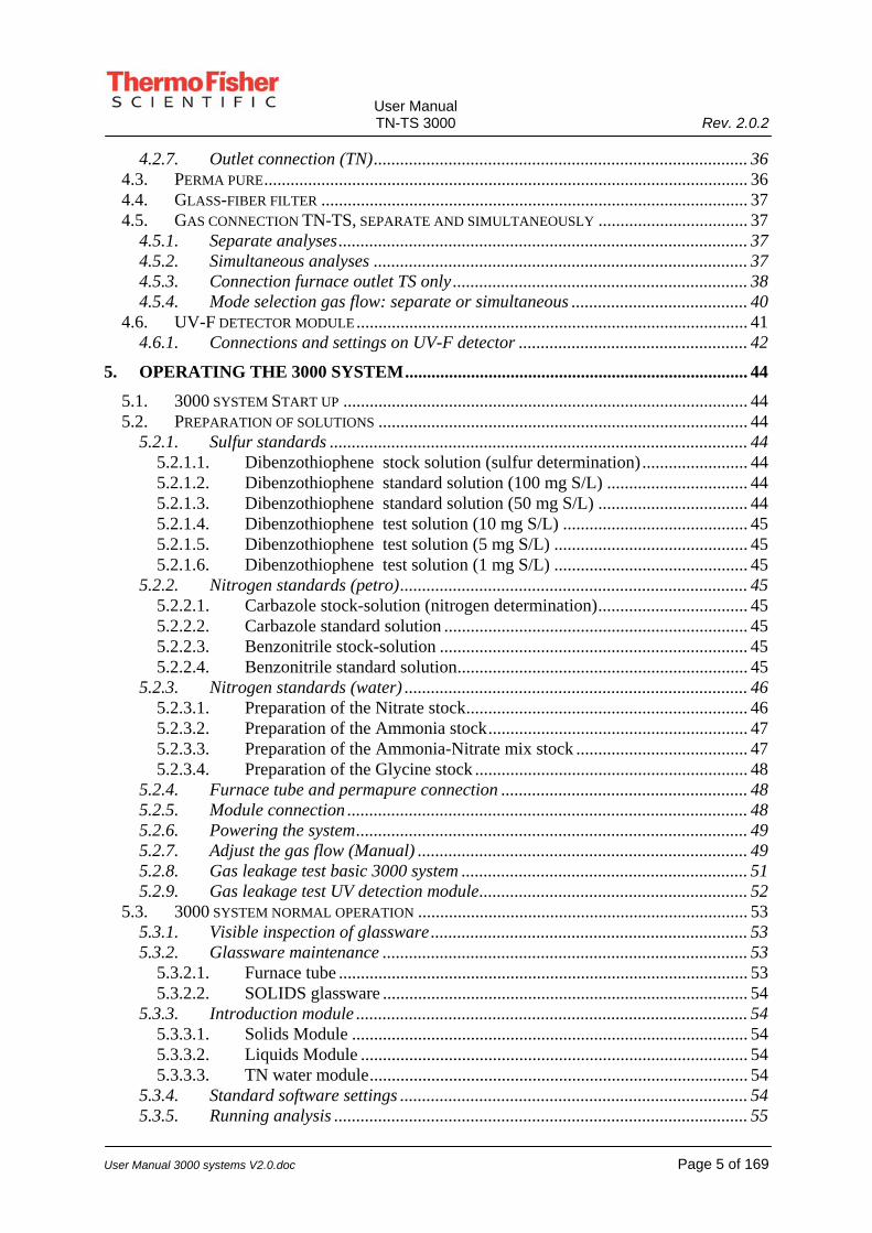
3.5.3. The "Solids module" universal This module uses a dual flow feed of gases to the module. The introduction and combustion of solids containing various compounds are in complete control. Both software and boat drive are in control of the positioning and travel speed of the sample. By introducing the sample into the argon/helium stream the sample evaporates at the appropriate temperature (controlled by the boat position) and combusts when oxygen is added. Conversion into SO2, HCl, HBr, CO2 etc, takes place. The detection compounds are optimally formed and the risk of incomplete oxidation is minimized.
Fig. Solids module universal

User Manual TN-TS 3000 Rev. 2.0.2
User Manual 3000 systems V2.0.doc Page 24 of 169
3.5.4. The "TN 3000 Solids module" With this module, a triple flow feed of gas is used. The introduction and combustion of solids containing nitrogen compounds is in complete control. By introducing a sample into the argon stream the sample evaporates at the appropriate temperature (controlled by the boat position) and combusts just in front of the catalyst where oxygen is added. Now conversion takes place directly over the catalyst. Nitric oxide is optimally formed and the chance of incomplete oxidation is reduced.
Fig. Solids module TN
The "Liquids Module Water" (Nitrogen according DIN) This module uses a double flow feed of gases into the module. The introduction and combustion of water samples containing nitrogen compounds are in complete control. By introducing a sample into the argon/helium stream, the sample vaporizes at high temperature and combusts when oxygen is added. Conversion into NO takes place. Nitrogen dioxide is optimally formed and the chance of incomplete oxidation is reduced.
Fig. Water module

User Manual TN-TS 3000 Rev. 2.0.2
User Manual 3000 systems V2.0.doc Page 25 of 169
3.5.5. The "TN 3000 Liquids Module" for light hydrocarbons With this module by using a triple flow feed of gases to the module, the introduction and combustion of organic solvents, light hydrocarbons and nitrogen compounds are in complete control. By introducing a sample into the argon stream it is vaporized at the correct temperature and just before the catalyst, oxygen is added. Now conversion takes place over the catalyst. Nitric oxide is optimally formed and the chance of incomplete oxidation is reduced.
Fig. Dedicated TN liquids module
3.6. Furnace According to ASTM requirements, the furnace is divided into two temperature zones. The temperature in each zone can be adjusted individually, up to 1100°C. Maximum temperature difference between the zones is approximately 500°C. Two different furnace tubes are available: A. Standard furnace tube (for water applications and non-
combustibles) B. Turbo tube (for petrochemical/hydrocarbon applications and
other “highly flammables”) Both furnace tubes are supporting all available introduction modules.
3.6.1. Standard furnace tube Actually, this is an empty tube mostly used for water samples where chance of soot formation is practically excluded.

User Manual TN-TS 3000 Rev. 2.0.2
User Manual 3000 systems V2.0.doc Page 26 of 169
3.6.2. Turbo tube This tube consists of an extra introduction for oxygen at the rear end of the furnace tube. (the longer leg at the outlet side) To optimize combustion of organic solvents, extra oxygen is added and to improve mixing of combustion gas, a spiral is placed into the second part of the furnace.
fig. Turbo combustion tube

User Manual TN-TS 3000 Rev. 2.0.2
User Manual 3000 systems V2.0.doc Page 27 of 169
3.7. Conditioning
3.7.1. Drying The gas flow coming from the furnace travels through a Perma pure membrane dryer. The principle of the nafion perma pure membrane dryer is the diffusion of water out of the gas stream, by co-polymers with sulfuric acid ligands.
Fig. Schematic explanation of water removal
3.7.2. C.F.I.S. (patented) Stability of flow and pressure are extremely important for repeatability and precision, especially for the ultra low ranges. The “Controlled Flow Introduction System” is implemented to avoid flow differences in the reaction chambers. A combination of the controlled combustion, flow restrictions, pressure control and vacuum devices are used for the control. The total implementation of this process is a patented system by Thermo Fisher Scientific.
User Manual TN-TS 3000 Rev. 2.0.2
User Manual 3000 systems V2.0.doc Page 28 of 169
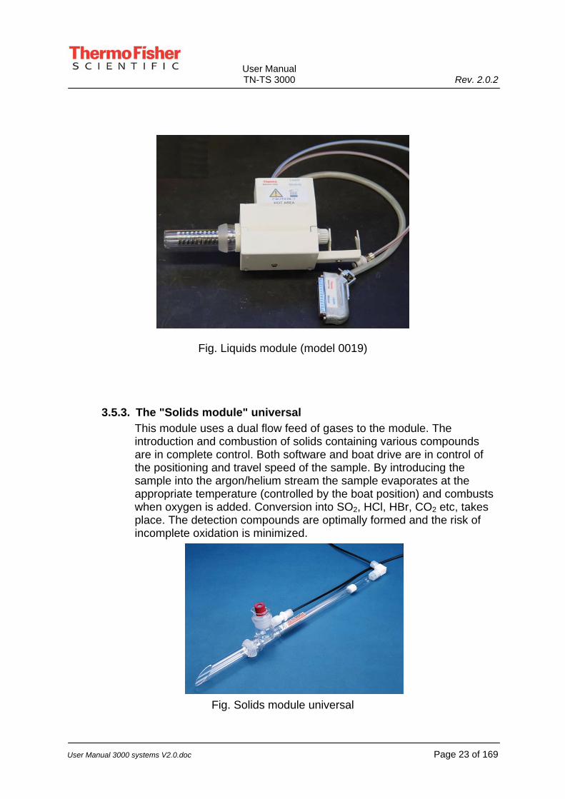
3.7.3. Molybdenum converter The molybdenum converter is installed behind the particle filter assembly. The function of the converter is to reduce NO2 into NO. This will improve the linearity dramatically, especially in the low range. The operational temperature is 320°C and is controlled by the software and displayed in the “Analyzer window”.
Fig. Molybdenum converter
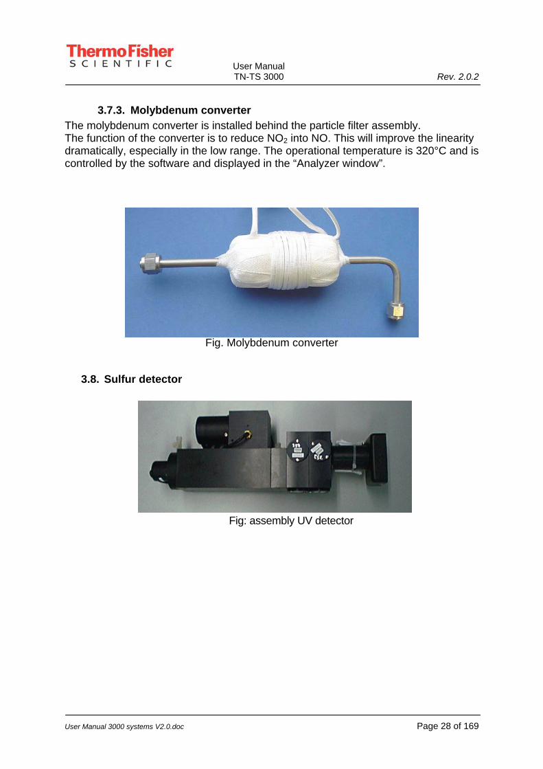
3.8. Sulfur detector
Fig: assembly UV detector

User Manual TN-TS 3000 Rev. 2.0.2
User Manual 3000 systems V2.0.doc Page 29 of 169
3.9. Photo Multiplier Tube The basic principle of the PMT’s in both the Sulfur- and Nitrogen detector are similar. Both PMT’s are sensitive to the emitted light, but at different wavelengths. Smart filter and mirror assemblies will filter out undesirables. The PMT only amplifies the selected wavelength. A graphical representation of the PMT is found below. The PMT housing is cooled with the use of a peltier element, in order to reduce dark current.
Fig. Photo Multiplier Schematic example of PMT layout. Once the received light enters the focussed area, a cascade multiplier amplifies the total signal.

User Manual TN-TS 3000 Rev. 2.0.2
User Manual 3000 systems V2.0.doc Page 30 of 169
3.10. Detector for Nitrogen
1. PMT housing 2. Gold plated, heated reaction chamber 3. Capillary location (heated) 4. Gas output 5. Ozone input 6. Analyses gas input 7. Heater connection 8. Photo Multiplier connections 9. Cooling block PMT (Peltier driven)
9
6
53 7
12
4
8

User Manual TN-TS 3000 Rev. 2.0.2
User Manual 3000 systems V2.0.doc Page 31 of 169
4. INSTALLATION OF THE 3000 SYSTEM
4.1. Introduction Before running actual samples on the 3000 system an overall check and installation procedure has to be carried out. This chapter will guide you through the installation procedure.
4.2. 3000 system, external connections and specifications All external connections are on the backside of the 3000 system. 1. Power connections 2. Communication connections 3. Gas connections and specifications In the next paragraphs, all connections are discussed.
4.2.1. Power connections
The power cable has to be connected to the 3000 system. The 3000 system has two additional power-outputs of 150 VA.
Figure: power sockets 3000 system

User Manual TN-TS 3000 Rev. 2.0.2
User Manual 3000 systems V2.0.doc Page 32 of 169
Warning Before turning the 3000 system on for the first time, the voltage setting must be checked. The small plate beneath the power lead should be positioned in a way that the 230 V indication is in the normal position (not upside down) and is read from left to right when the operator is facing the back of the apparatus. The 115 V indication will then be upside down. Should you need to switch from a 230 V to a 115 Volts supply, pull the plate away from the instrument so that the prongs of the plug are fully withdrawn from the apparatus and re-insert the other way up.
Electrical Hazard Do not open the cabinet when the power cable is connected. Remove it from the wall outlet and disconnect the cable from the analyzer completely.
Special Attention After supplying power to the analyzer and starting the program, the furnaces and heating elements will rise to the standard temperatures required by the connected module. (initialization procedure) When no module is connected, the apparatus will go into standby mode (i.e. no furnace control).
4.2.2. Communication connections The RS232-communicationcord (9 pins) is connected to the 3000 system on the serial port connection. The other side of this cable (9pins) is connected on the COM1-port of the computer.
Figure: com-connector
Warning Wrong connections could lead to malfunction of the analyzer or computer.

User Manual TN-TS 3000 Rev. 2.0.2
User Manual 3000 systems V2.0.doc Page 33 of 169
4.2.3. Gasses: connections and specifications Gas, to be provided by the customer, has to be connected to the 3000 system. The gas specifications for Argon/Helium and Oxygen are:
Argon/Helium (Ar) (He) 99.998% (or better*) Oxygen (02) 99.6% (or better*) Maximum pressure 2-3 bar* Gas connection 1/8”
Figure: gas connections, back-side (1/8” Swagelok)
*Notes* Preferred pressure settings. For “manual flow meters” advised pressure is 1-3 bar For “mass flow meters” advised pressure is 1-2 bar Gas quality/specifications. For most applications the above mentioned specifications are valid. For ultra low level Nitrogen analysis, the specifications may differ. Usually Argon and Helium are of sufficient quality for analysis below 100 ppb.
Specs for Oxygen (ultra low application): 99.998% (or better)
Background information: Oxygen will most likely contain a small amount of nitrogen as well. This is normal, considering the process for oxygen production. The better the oxygen, the lower the expected background is. Oxygen is also the larger part of the total carrier gas used in the 3000 system. During combustion, NOx may be formed from the oxidation of mainly hydrocarbons in the presence of nitrogen gas. (the background in the oxygen) This will produce higher areas for blanks and ultra low standards, affecting the detection capability of the 3000 system. Most interference’s are covered by the system itself. The gas quality however should be addressed at the source. Check with your local gas supplier for the details.

User Manual TN-TS 3000 Rev. 2.0.2
User Manual 3000 systems V2.0.doc Page 34 of 169
4.2.4. 3000 system glassware connections Connect the glass parts using the proper clamps. Make sure that the connecting areas are clean and free of particles. Check for leakage between connections in order to ensure correct operation. The glassware parts are: 1. Sample introduction module 2. Furnace tube 3. Outlet connection
In the next paragraphs, all connections will be discussed.
4.2.5. Sample introduction modules
There are a few differences between the introduction modules for the 3000 system. Two of them have to be installed differently. The introduction modules are easily interchangeable. Make sure that the furnace tube (when installed) is supported by the stainless steel fork.
The different introduction modules are: 1. The "Liquids/Gas module" 2. The "Solids module" 3. The “Water module”
4.2.5.1. The "Liquids module" Slide the Liquids module into the furnace tube. Connect the gas connectors (O2: blue on blue and Ar: white on white). Place the clamp tightly on the connected glass parts and install the Liquids identity-connector. In case of multiple gas connectors, select the oxygen connector on the left. This one corresponds with the second flow meter from the right! The right flow meter corresponds with the oxygen connector on the right!
4.2.5.2. The "Solids module" Slide the Solids module into the furnace tube. Make sure that the white Teflon magnet in the boat module is positioned just above the white Teflon boat driver. The actual movement of the boat is transferred using magnets, incorporated in the Teflon. Plug-in the gas connectors (O2: blue on blue Ar: white on white). Place the clamps tightly on the connected glass parts and install the “Solids identity-connector”. In case of multiple gas connectors, select the oxygen connector on the left. This one corresponds with the

User Manual TN-TS 3000 Rev. 2.0.2
User Manual 3000 systems V2.0.doc Page 35 of 169
second flow meter from the right! The right flow meter corresponds with the oxygen connector on the right!
4.2.5.3. The "Liquids module Water" Introduce the Water module into the furnace tube and make sure that the solid i.d. connector is in place. Place the clamp over the glass connectors and check if connecting surfaces are clean. Insert the gas connectors. (the single O2: blue on blue, using the left oxygen connector. Ar: white on white and the mixed oxygen connector into the right one) Note: A special TN-Water analyzer is also available. For this analyzer is an additional manual.
4.2.6. Furnace tube Slide the quartz furnace tube into the furnace compartment with the narrow end towards the outlet side. Place the stainless steel fork for correct support in the boat-driver. (module connection side of the tube)
Special Attention Avoid touching the surface of the furnace tube with your bare fingers. The traces of grease left by your fingertips will create hotspots and reduce the service life of the furnace tube.
The furnace tube and outlet become very hot during the operation of the 3000 system. Carelessness may result in burns. Avoid contact with bare hands. Use special protective gloves and/or tools for “hot tube removal”. The safest way for removal is allowing the furnace to cool down completely.

User Manual TN-TS 3000 Rev. 2.0.2
User Manual 3000 systems V2.0.doc Page 36 of 169
4.2.7. Outlet connection (TN) Connect the outlet glass-connector to the Perma-pure first. When using a turbo furnace tube: connect the outlet glass connector to the shorter ball-joint (outlet side) and the extra O2 supply connector to the longer ball-joint . (O2 feed to the rear end of the turbo tube) see figure: gas connections/permapure below no: 1 and 7 The installation is similar to the perma-pure connection.
Figure: gas connections/permapure
4.3. Perma pure To place and connect the Perma pure dryer the following steps are necessary. Refer to figure: gas connections/permapure above.
1. Connect the inlet of the perma pure to the outlet glass-connector. 2. Connect the gas outlet coming from the vacuum pump to the outside inlet
(for drying) 3. Connect the outlet of the Perma pure to the green glass-fiber filter.

User Manual TN-TS 3000 Rev. 2.0.2
User Manual 3000 systems V2.0.doc Page 37 of 169
4.4. Glass-fiber filter Changing a filter requires the special green filter tool, provided with the accessories. Disconnect the inlet of the filter and remove the opaque side of the filter-house, using the provided tool. Replace the glass-fiber filter and reinstall all parts. There are basically two types of glass-fiber filters. One of them traps SO2 (paper like filter) and is therefore not suitable. Those are mainly used for TN analysis only. The one suitable for both TN and TS looks clearly like glass fiber. Check your application to verify if the correct one is installed. If a sulfuric acid scrubber is installed, the filter might be polluted by acid. It is therefore advised to change the filter after 2 days of measurement. Filters that are moist by acid, can easily cleaned by thoroughly rinsing them with distilled or de-ionized water. The cleaned filters can dry in the air at ambient temperature (for example, by placing them on a tissue). If the filter shows any damage or pollution, replace it with a new one.
4.5. Gas connection TN-TS, separate and simultaneously
4.5.1. Separate analyses Total Sulfur can be measured in combination with Nitrogen or other Elements. A tubing loop on the backside of the TN3000 analyzer dictates the flow path of the gas. With the loop fully connected, the TN only mode is secured. With the tubing from the UV-F detector connected to the lower connector only, the TS only mode is enabled. Pictures for the connections are found in chapter 4.5.4
4.5.2. Simultaneous analyses Simultaneous analyses is obtained by connecting the inlet tubing from the UV-F detector into the lower quick connector on the back of the TN3000. The output of the UV-F detector is connected to the upper fast connector at the back of the TN3000, leading the gas over the Molybdenum converter, (refer to chapter 3.7.3) before it enters the TN detector. Pictures for the connections are found in chapter 4.5.4.

User Manual TN-TS 3000 Rev. 2.0.2
User Manual 3000 systems V2.0.doc Page 38 of 169
Figure: Molybdenum converter
Note: If the PC is equipped with 2 interface boards and the proper software, simultaneous analyses are possible. Data cables are connected to the “I” sockets of the PC boards.
4.5.3. Connection furnace outlet TS only The TN detector applies ozone to the analysis gasses. Hence, this type of detector is characterized as using a destructive detection method. Therefore, the TS-UV detector always has to be placed in front of the TN detector. In principle, for gas conditioning the perma pure dryer will suffice. However, in order to create a more robust system (less sensitive to soot formation), an additional scrubber filled with concentrated sulfuric acid van be placed after the perma pure. See figure below:
Fig.: TS flow path
Note: Never use a sulfuric acid scrubber in combination with a TN
UV fluorescence detector

User Manual TN-TS 3000 Rev. 2.0.2
User Manual 3000 systems V2.0.doc Page 39 of 169
detector. Sulfuric acid reacts with NOx resulting in a too low recovery.
Fig.: Details Scrubber connections
Fig.: Combination perma pure with scrubber
Connection scrubber glass fiber filter (TS3000010) KS Clamp with screw nr.12
Sulfuric acid scrubber (ECS300006)
Connector to gasinlet (ECS30010) KS Clamp with screw nr.12 (PMECH0006)
In-line filter (PANAL0134)
Coupling (PMECH0368)

User Manual TN-TS 3000 Rev. 2.0.2
User Manual 3000 systems V2.0.doc Page 40 of 169
4.5.4. Mode selection gas flow: separate or simultaneous Sulfur Mode Only
Simultaneous Mode
TN Mode Only
Loop in upper connector only.
Gas inlet UV-F detector in lower position 3000.
UV-F input in lower connector.
UV-F output in upper connector. (into Molybdenum converter and TN detector)
Loop in both connectors. (outlet from particle filter goes into the molybdenum converter)

User Manual TN-TS 3000 Rev. 2.0.2
User Manual 3000 systems V2.0.doc Page 41 of 169
4.6. UV-F detector module
Figure: UV detector module

User Manual TN-TS 3000 Rev. 2.0.2
User Manual 3000 systems V2.0.doc Page 42 of 169
4.6.1. Connections and settings on UV-F detector
Figure: Backside UV-F detector
1. On/Off switch, 230-115 Volt selectable. 2. Power socket. 3. Coaxial connection for data transfer to PC board. (“I” socket PC Board) 4. Gas outlet UV-F detector (used for inlet towards TN detector, sometimes
already provided with tubing and fast connector.) 5. Cooling fan exhaust. 6. Range selectors. (0-5, 0-50, 0-500 PPM) Both switches in the “down
position” 0-5 range. Both in the upper position 0-500 range. Both switches pointing in different directions (preferably bottom switch down and upper switch up) enables the 0-50 range.
“High range” refers to high sulfur concentration. “Low range” refers to low sulfur concentration. Please note that the “Mid range” runs from 25ppb up to approximately 50 ppm!!
1
3
4
2
5
6

User Manual TN-TS 3000 Rev. 2.0.2
User Manual 3000 systems V2.0.doc Page 43 of 169
For most applications the mid-range is considered the “ideal working range”
Warning Before turning the UV detector module on for the first time, the voltage setting must be checked. The small plate beneath the power lead should be positioned in a way that the 230 V indication is in the normal position (not upside down) and is read from left to right when the operator is facing the back of the apparatus. The 115 V indication will then be upside down. Should you need to switch from a 230 V to a 115 V supply pull the plate away from the instrument so that the prongs of the plug are fully withdrawn from the apparatus and re-insert the other way up.
Electrical Hazard Do not open the cabinet before the power cable is removed.
Special Attention With power supplied to the UV detector, the heating elements will rise to the standard temperature required for optimum performance.

User Manual TN-TS 3000 Rev. 2.0.2
User Manual 3000 systems V2.0.doc Page 44 of 169
5. OPERATING THE 3000 SYSTEM After installation, the 3000 system is ready for operation. The following paragraphs should be read carefully. Please note that the software manual should be read before the 3000 system is switched on.
Special Attention Read the software manual for the 3000 system before operating the 3000 system.
5.1. 3000 system Start up Before starting the 3000 system, several standards should be prepared. In the next paragraphs the following subjects are described:
1. Preparation of standards 2. Furnace tube and permapure connection 3. Module connection 4. Powering the system 5. Adjust gas flow 6. Gas leakage test
5.2. Preparation of solutions All necessary solutions, needed for good analysis are described below.
5.2.1. Sulfur standards
5.2.1.1. Dibenzothiophene stock solution (sulfur determination) To make a stock solution of dibenzothiophene dissolve 1436.66 mg of dibenzothiophene (= diphenylene sulfide; C12H8S) in 200 mL xylene (= 1,2-dimethylbenzene, 1,2-(CH3)2C6H4; p.a.). Fill with xylene to 250 mL. Mix the solution thoroughly.
5.2.1.2. Dibenzothiophene standard solution (100 mg S/L) Pipette 10 mL of the dibenzothiophene stock solution in a 100 mL measuring flask and with xylene to 100mL. Mix the solution thoroughly.
5.2.1.3. Dibenzothiophene standard solution (50 mg S/L) Pipette 5 mL of the dibenzothiophene stock solution in a 100 mL measuring flask and with xylene to 100mL. Mix the solution thoroughly.

User Manual TN-TS 3000 Rev. 2.0.2
User Manual 3000 systems V2.0.doc Page 45 of 169
5.2.1.4. Dibenzothiophene test solution (10 mg S/L) Pipette 10 mL of the dibenzothiophene standard solution in a 100 mL measuring flask and with xylene to 100 mL. Mix the solution thoroughly.
5.2.1.5. Dibenzothiophene test solution (5 mg S/L) Pipette 5 mL of the dibenzothiophene standard solution in a 100 mL measuring flask and with xylene to 100 mL. Mix the solution thoroughly.
5.2.1.6. Dibenzothiophene test solution (1 mg S/L) Pipette 10 mL of the dibenzothiophene test solution (10 mgS/L) in a 100 mL measuring flask and with xylene to 100 mL. Mix the solution thoroughly.
5.2.2. Nitrogen standards (petro)
5.2.2.1. Carbazole stock-solution (nitrogen determination) In a 1000 mL volumetric flask 11.937 g of carbazole has to be dissolved with approximately 800 mL acetone. Fill the flask with acetone to 1000 mL after dissolving the carbazole for the preparation of this carbazole stock-solution with a nitrogen concentration of 1000 mg N/L. Homogenize the solution.
5.2.2.2. Carbazole standard solution Pipette 10 mL of the stock-solution into a volumetric flask of 100 mL and fill the flask to 100 mL with acetone. The homogenized standard solution contains 100 mg N/L.
5.2.2.3. Benzonitrile stock-solution In a 250 mL volumetric flask 9.20 mg of benzonitrile has to be diluted1 with approximately 200 mL toluene. Fill the flask with toluene to 250 mL after dissolving the benzonitrile for the preparation of this benzonitrile stock-solution with a nitrogen concentration of 5000 mg N/L. Homogenize the solution.
5.2.2.4. Benzonitrile standard solution Pipette 20 mL of the stock-solution into a volumetric flask of 100 mL and fill the flask to 100 mL with toluene. The homogenized standard solution contains 1000 mg N/L.

User Manual TN-TS 3000 Rev. 2.0.2
User Manual 3000 systems V2.0.doc Page 46 of 169
5.2.3. Nitrogen standards (water) The Thermo Fisher Scientific TN3000-water analyzer is capable to measure total Nitrogen in aqueous samples in a range of 0.2 to 100 ppm N. Since the working principle of this analyzer is based on the combustion of samples in the presence of oxygen, it is obvious that the conversion of samples into nitric oxide (NO) is strongly dependent on the type of nitrogen containing molecules. For example, Ammonia (NH4+) will consume much more oxygen than Nitrate (NO3-). Hence, these molecules will generate a different yield in case analyzed simultaneously. The TN3000-water is guaranteed to keep this Ammonia-Nitrate ratio below 10% deviation according to the NVN-EVN 12260 and DIN 38409 norms, within the range 0.2 up to 25 ppm. Preparation of the standards Standard a TN water is calibrated with a range of Glycine standards. If Ammonia and/or Nitrate is important, the system can be calibrated with separate standards or with a mix standard. If totally different types of samples have to be measured, it is advisable to calibrate with more representative standards. In below shown table, the mass that has to be weighed for the most commonly applied standards.
Nitrate standards are, in general, a very good nutrition source for microorganisms. Always store the standards in a cool (approx. 5 °C) and dark place.
5.2.3.1. Preparation of the Nitrate stock Exactly weigh 7221 mg of anhydrous Potassium Nitrate. Quantitatively transfer it to a measuring flask of 1000 mL using de-ionized or distilled water. Exactly fill the flask to 1000 mL. Mix (shake) the solution thoroughly.
Nitrate Ammonia GlycineConc. N mg KNO3 mg (NH4)2SO4 mg KNO3 and mg (NH4)2SO4 mg C2H5NO2
Name Formula MM Molfr N mg N/L per L per L per L per L
Potassium Nitrate KNO3 101.1 0.138 1 7.22 4.72 3.61 + 2.36 5.36Ammonium Sulfate (NH4)2SO4 132.13 0.212 2 14.44 9.44 7.22 + 4.72 10.72Glycine C2H5NO2 75.06 0.187 5 36.11 23.59 18.05 + 11.80 26.81
10 72.21 47.19 36.11 + 23.59 53.6125 180.54 117.97 90.27 + 58.99 134.0450 361.07 235.95 180.54 + 117.97 268.0775 541.61 353.92 270.80 + 176.96 402.11
100 722.14 471.89 361.07 + 235.95 536.14Stock solution >>> 1000 7221.43 4718.93 3610.71 + 2359.46 5361.43
Mix

User Manual TN-TS 3000 Rev. 2.0.2
User Manual 3000 systems V2.0.doc Page 47 of 169
5.2.3.1.1. Preparation of the 100 ppm Nitrate standard Pipette 10 mL of the Nitrate stock solution into a measuring flask and fill to 100 mL with de-ionized or distilled water. Mix the solution thoroughly.
5.2.3.1.2. Preparation of the 50 ppm Nitrate standard Pipette 5 mL of the Nitrate stock solution into a measuring flask and fill to 100 mL with de-ionized or distilled water. Mix the solution thoroughly.
5.2.3.1.3. Preparation of the 25 ppm Nitrate standard Pipette 2.5 mL of the Nitrate stock solution into a measuring flask and fill to 100 mL with de-ionized or distilled water. Mix the solution thoroughly.
5.2.3.1.4. Preparation of the 10 ppm Nitrate standard Pipette 1 mL of the Nitrate stock solution into a measuring flask and fill to 100 mL with de-ionized or distilled water. Mix the solution thoroughly.
5.2.3.1.5. Preparation of the 5 ppm Nitrate standard Pipette 5 mL of the Nitrate stock solution into a measuring flask and fill to 1000 mL with de-ionized or distilled water. Mix the solution thoroughly.
5.2.3.1.6. Preparation of the 1 ppm Nitrate standard Pipette 1 mL of the Nitrate stock solution into a measuring flask and fill to 1000 mL with de-ionized or distilled water. Mix the solution thoroughly.
5.2.3.2. Preparation of the Ammonia stock Exactly weigh 4718 mg of anhydrous Ammonia Sulfate. Quantitatively transfer it to a measuring flask of 1000 mL using de-ionized or distilled water. Exactly fill the flask to 1000 mL. Mix (shake) the solution thoroughly.
5.2.3.2.1. Preparation of the x ppm Ammonia standard Please follow the same procedure as described for the Nitrate standards using the Ammonia stock solution. (Paragraph: 5.2.3.1.)
5.2.3.3. Preparation of the Ammonia-Nitrate mix stock Exactly weigh 3610 mg anhydrous Potassium Nitrate and 2359 mg anhydrous Ammonia Sulfate. Quantitatively transfer both salts to a measuring flask of 1000 mL using de-ionized or distilled water. Exactly fill the flask to 1000 mL. Mix (shake) the solution thoroughly.

User Manual TN-TS 3000 Rev. 2.0.2
User Manual 3000 systems V2.0.doc Page 48 of 169
5.2.3.3.1. Preparation of the x ppm Ammonia-Nitrate mix standard Please follow the same procedure as described for the Nitrate standards using the Ammonia-Nitrate mix stock solution. (Paragraph: 5.2.3.1.)
5.2.3.4. Preparation of the Glycine stock Exactly weigh 5361 mg Glycine. Quantitatively transfer it to a measuring flask of 1000 mL using de-ionized or distilled water. Exactly fill the flask to 1000 mL. Mix (shake) the solution thoroughly.
5.2.3.4.1. Preparation of the x ppm Glycine standard Please follow the same procedure as described for the Nitrate standards using the Glycine stock solution. (Paragraph: 5.2.3.1.)
5.2.4. Furnace tube and permapure connection Slide the furnace tube into the oven and connect the permapure to the outlet to the furnace using the outlet glass-connector. Connect all tubing to the permapure as described in paragraph 4.3
5.2.5. Module connection Place the introduction module and connect all the tubing. Connect the module with the clamp to the furnace tube. Install all gas connections (blue at blue and white at white) and the ID-connector belonging to the module. (refer for detailed info for the specific modules to 3.5 and 4.2.5

User Manual TN-TS 3000 Rev. 2.0.2
User Manual 3000 systems V2.0.doc Page 49 of 169
5.2.6. Powering the system If all steps above are carried out carefully and the instrument is connected to a computer, the 3000 system can be switched on with the ON/OFF switch on the backside of the instrument. 1. Switch on the 3000 system (note that the detectors needs a 30
minute startup before operational temperatures and general performance conditions are reached. In case of UV start-up a dim ticking is heard after a few seconds. This is the UV Flasher lamp and is considered a normal sound. The TN detector heat-up as soon as the basic unit is switched on, without any particular sound.
2. Switch on the vacuum pump (small switch at the back-side) 3. Switch on the computer 4. Start the TN/TS analyzer software by clicking on the Thermo Fisher
Scientific software icon. 5. Check if communication is established between PC and the 3000
system. This is visually checked in the “System status screen”. If there is no communication, please check if the correct “com port” is selected or actually connected. Furnace temperatures and system parameters can be adjusted and monitored.
6. Check if both the UV module and/or the TN outputs are connected to the data acquisition board(s) and if a baseline signal appears. The data cable runs from detector into the “I” socket of the data acquisition board in the PC. Without the correct settings, the signal of the UV detector could appear to be noisy.
At this point the instrument needs time to stabilize.
5.2.7. Adjust the gas flow (Manual) Note: Depending on the configuration, manual or digital gas flow controllers are installed. In case digital mass flow controllers are installed, all settings will be automatically done by the ThEuS software. Below described steps are in that case not necessary. Before operation, gases have to be supplied with a maximum pressure of 3 bar. (normal flow meters as seen below) The supplied gas tubing can be used to hook-up the analyzer. Open the gas headers on the gas supply line in the following order. 1. Close all flow meters by turning the black knob in the clockwise
direction. (do not over-tighten) 2. Open the gas headers on the gas supply line. 3. Open the flow meters by turning the black knob counter clockwise.

User Manual TN-TS 3000 Rev. 2.0.2
User Manual 3000 systems V2.0.doc Page 50 of 169
Figure: Flow meters
The introduction module has to be installed before the five flow meters are adjusted. From right to left:
A. Argon/Helium flow meter B. Oxygen Furnace flow meter C. Oxygen Extra flow meter D. Oxygen Bypass flow meter E. Oxygen Ozone flow meter The different settings for water, organic -liquids and -solids are given at Appendix I. Note: The number of manual flow meters can differ per system depending on the configuration.
A E

User Manual TN-TS 3000 Rev. 2.0.2
User Manual 3000 systems V2.0.doc Page 51 of 169
5.2.8. Gas leakage test basic 3000 system Procedure 1 For reliable and accurate analysis the 3000 SYSTEM needs to be free of leakage. Therefore a gas leak test has to be performed. The next steps explain the gas leak test: 1. Close the flow meters for the oxygen-supply and lower the Argon-flow to
approximately 5 mm. 2. Disconnect the permapure from the particle filter and insert a separate piece of
tubing into it (length about 50 cm and diameter ¼”) 3. Fill a small beaker with water and insert the outer part of the tubing into the water. 4. Observe the flow in the beaker. There still has to be a low flow of bubbles visible. 5. This demonstrates that even at low flow-rates the gas coming from the permapure
dryer, arrives without significant leakage. Gas leakage test ok > proceed with analysis. Gas leakage test false > proceed with next steps.
The furnace tube, outlet, modules, joints, etc may become very hot during the operation of the 3000 SYSTEM. Carelessness may result in burns.
Procedure 2 1. If there are no bubbles visible, a gas leakage has to be fixed. Adjust flows to the
“normal” levels. (setting according current method) 2. Disconnect the gas stream between furnace output and the “permapure
connection”. 3. Manually obstruct the gas stream on the outlet of the furnace tube (using a
septum) and observe the flow meters. They should drop approximately 5-10 mm within 10-15 seconds. (do not block the flows longer than that) Removing the septum from the output should clearly release pressure from the tube. This indicates that no gas-flow leakage is present in the connectors, Module, Furnace-tube and other joints. The leakage has to be further down the flow path. (leakage could be found in the septum of the module, any gas connector, glass joints, loose clamps, mineralized furnace tube, etc.)
4. Connect the “permapure dryer” again and obstruct the flow, coming from it. The flow meters should drop approximately 5-10 mm within 10-15 seconds. Removing the septum from the output should clearly release pressure from the permapure dryer. This indicates that no gas-flow leakage is present in all connected parts in

User Manual TN-TS 3000 Rev. 2.0.2
User Manual 3000 systems V2.0.doc Page 52 of 169
the flow path. The leakage has to be further down the flow path. (leakage could be found in the gas connector going to the particle filter, the glass joints, due to dirt on the grind surface, the furnace tube ball-joint, etc.
5. Resolve any other leakage problem found in the flow path and test it. 6. Finally connect a separate piece of tubing to the outlet connection of the particle
filter (see picture chapter 4.5.4 )and run the test from “procedure 1” again. 7. The final check will be the number 3-5 step from procedure 1. Following these steps should clearly lead to the “problem” and solution in the flow path.
5.2.9. Gas leakage test UV detection module For reliable and accurate analysis the 3000 system needs to be free of leakage. Therefore, a gas leak test has to be performed.
The next steps will guide you trough a gas leak test: 1. Check all connections and glassware for proper installation. 2. Close the oxygen-supply and adjust the Argon/Helium flow to 5 mm. 3. Connect a piece of tubing to the gas outlet of the 3000 system, or
the outlet of the UV module. 4. Put the outlet of the tubing in a glass beaker with water and observe
if small bubbles appear. (if not than a leakage or blockage is most likely)
5. Reconnect the UV module (if applicable) and set gas flows to proper levels again.
6. Cleaning glass connections, replacing septa and maintaining all connectors in proper condition should prevent most of the leakage problems.

User Manual TN-TS 3000 Rev. 2.0.2
User Manual 3000 systems V2.0.doc Page 53 of 169
5.3. 3000 system normal operation The software controls the operation of the 3000 system. Methods are described in the 3000 system software manual. During normal operation, regularly small maintenance has to be carried out. The next paragraphs will describe the following subjects:
1. Visible inspection of glassware 2. Glassware maintenance 3. Introduction module 4. Standard set points
5.3.1. Visible inspection of glassware All glassware parts should be checked regularly, once a week, on scratches, disposals and blocking of the gas path. After the inspection a gas leak test should be performed. The frequency of inspection depends strongly on the sample matrix. Samples containing high concentration of salts or metals could increase the number of inspections. It is considered normal that the service life of quartz is reduced because of this.
5.3.2. Glassware maintenance
5.3.2.1. Furnace tube In the furnace tube soothing is one of the causes of the memory effect. Mineralization can also cause the same effect (the tube sometimes becomes slightly porous). Soot deposited at the end of the furnace tube is relatively easy to remove. 1. Remove the clamp between the tube and the Perma pure.
(end of the tube) 2. Remove the clamp of the “turbo oxygen”. (end of the tube) 3. Remove the clamp which connects the module to the tube
(front of tube) and remove the module. 4. Remove the latch (stainless steel fork) between the tube
and the module. (front of tube) 5. Set the furnace temperature to 1000 oC and pull back the
tube halfway (it should be clean in 10 minutes).
The tube could become opaque on the inside and sometimes on the outside. This is recognized as mineralization of the furnace tube. In some cases, Thermo Fisher Scientific can remedy this. Please contact the Thermo Fisher Scientific Service Department or your local representative for more information.

User Manual TN-TS 3000 Rev. 2.0.2
User Manual 3000 systems V2.0.doc Page 54 of 169
5.3.2.2. SOLIDS glassware During solids analysis, the boat and/or frit after many analyses may cause a memory effect. By introducing samples into the furnace tube too fast, condensation could appear into the sample introduction section of the solids glassware. If this happens, a second peak can occur when the hot boat returns from the furnace. If this is visible, the glassware must be cleaned in an oven at approximately 500 oC. Please contact the Thermo Fisher Scientific Service Department for more information. The effect may be caused by mineralization of either the boat or the frit, or both. Replacing them may be the only solution. The service life of the sample crucible and the boat often depends on the number of runs, the nature and components in the sample.
5.3.3. Introduction module
5.3.3.1. Solids Module Replace the septum when necessary but at least every week. If a new sample boat is used or the boat is dirty, clean this by introduction into the furnace tube during 4 minutes at 1000 oC.
5.3.3.2. Liquids Module Replace the septum when necessary, but at least once every week. (service lifetime when auto sampler is used is usually longer)
5.3.3.3. TN water module This is a special module and is supplied with additional hardware. Please refer to the separate TN-water user manual for details.
5.3.4. Standard software settings The software controls most of the set points. These parameters are related to a method. These methods describe all parameters necessary for running a number of applications. The software manual describes how these methods are made. An example of set points is given at Appendix I. For more information refer to the software manual.

User Manual TN-TS 3000 Rev. 2.0.2
User Manual 3000 systems V2.0.doc Page 55 of 169
5.3.5. Running analysis
In this paragraph a brief explanation will be given how to start working with the ThEuS™ software supplied with the analyzer. For more details please refer to the manual on the ThEuS™ CD or to the interactive manual build into the help function of ThEuS™.
5.3.5.1. Starting ThEuS™ ThEuS™ is installed on the computer supplied by the system. Also a CD is included in the shipment. If no computer was included, please install ThEuS™ by inserting the CD into de CD-drive of the computer connected to the analyzer. The installation will start automatically. Please refer to the installation manual for more details. Start ThEuS™ by clicking the icon on the desktop:
If the system is installed by an engineer from Thermo, the right configuration and method(s) are already installed on the computer. If not, please contact your local Thermo representative. After ThEuS™ is started a queue of samples must be entered.
To do this, open the Queue manager.
In the following window, click the New Queue button and enter a name for the Queue that has to be created.

User Manual TN-TS 3000 Rev. 2.0.2
User Manual 3000 systems V2.0.doc Page 56 of 169
Next, click the Add button. The following window will appear:
For analyzing samples, not creating a calibration line, select as ‘Type’ sample. Then enter the following data in the boxes: Sample name The name of the sample to be analyzed Amount The quantity of the sample + unit (pull down) Concentration unit Pull down selection: Unit in which the result will be
calculated/shown Begin sample position If an auto sampler is present, in this box the
position of the sample is entered. Note: If in the box ‘Number of samples’ a value larger then 1 is entered, this box will indicate the start position of first sample in a row.
Dilution If the sample has been diluted in this box the dilution factor can be entered. Note: By double clicking on this box a dilution calculation wizard is activated. Please refer to the software manual for more details.
Density If for example the sample is dissolved in toluene the density (e.g. 0.85) for this solution can be entered. This value is used for calculating the analyzed concentration.
Method Depending on the configuration of the system, one or more methods available. Select from this pull down menu the right method. Note: A method is sequence of action steps necessary for performing an analysis. Refer to the software manual for more details.
Analyst name Enter the name (your name) of the analyst Sample Comment In this box additional information can be entered.
This information will be stored together with the analysis results.

User Manual TN-TS 3000 Rev. 2.0.2
User Manual 3000 systems V2.0.doc Page 57 of 169
Number of samples Normally 1 is entered. However, if more similar (duplicate) samples have to be analyzed, a value larger then 1 can be entered. Note: This will only work when an auto sampler is present. Also see Sample start position.
Analysis per sample In this box the number this sample has to be analyzed has to be entered.
After all parameters have been entered, click the OK button. Above shown example will generate the following queue:
By clicking the Add button again, the next (set of) sample(s) can be added. Repeat this action until all desired samples have be added to this queue. When finished adding samples click the analyze button. A similar window will appear: Make sure ‘Analyze Queue’ is selected (tagged) in order to analyze the whole queue. Then click the OK button. The analyses will start. Note: If no auto sampler is present, a question will pop up asking the user to inject/insert the sample.

User Manual TN-TS 3000 Rev. 2.0.2
User Manual 3000 systems V2.0.doc Page 58 of 169
5.3.5.2. Creating a calibration Creating a calibration line is similar to analyzing samples as described in the previous paragraph. Instead of selecting ‘sample’ as type, select ‘calibration’. In addition to the normal ‘sample’ information, the name of the calibration line and the known concentration have to be entered.
If in the box ‘calibration line’ the option new is selected, a new calibration set will be created. In that case a new name is requested:
In this menu, the new name the calibration order, signal and through zero has to be selected/entered. The order is in case of a coulometer (TX and TS) Is used, the order should be ‘Absolute’, otherwise in most cases a first order (linear) is applied. Note: Afterwards the order can always be changed. If the system has more then one (parallel) detector the desired signal has to be selected. ‘Through zero’ is used to force the calibration line through the zero point (0,0). Similar to analyzing samples, by clicking the ‘analyze’ button, the calibration standards are measured and calculated into a calibration curve. For more details please refer to the manual provided with the software.

User Manual TN-TS 3000 Rev. 2.0.2
User Manual 3000 systems V2.0.doc Page 59 of 169
5.4. Quick performance check TN/TS mode Before actual samples are introduced an overall performance of the 3000 system must be performed. If these test results are within the specification, samples- and calibration procedures may be carried out, without further system proofing. Before actual shipment to the final destination of the system a “factory calibration” is carried out. This information is found in the test report, sent along with the system. In the report test results and calibration data is found. The data clearly shows the generated area for a specific standard. This value may be used as an “absolute reference” for system performance. By injecting standards with an injection speed of 1µL/s, using the appropriate “liquids module” manually or with the auto sampler a comparable result should be found.
5.4.1. TN mode test (setting is low range) A 100 mg N/L standard is injected at 1 µL/s. With flow- and temperature settings according the “liquids application” for hydrocarbons the integrated area generated for a 50 µl injection volume should be approximately 100.000 mV. For 100 µL it should be 200.000 mV. Maximum signal level is approximately 2100 mV. Above this level the signal may appear flat-lined, indicating that the maximum level is reached and the result of the total integration should be ignored. Double-checking it with a 50 mg N/L standard should give half the area. If the above mentioned areas are obtained, the system functions correctly and calibration and analysis may be carried out. Incorrect areas (reduced with10% or more) are an indicator of malfunction. In this case gas test 5.2.8 and overall system check will have to be carried out.
5.4.2. TS-UV mode test (setting is mid-range) A 50 mg S/L standard is injected at 1 µL/s. With flow- and temperature settings according the “liquids application” for hydrocarbons the integrated area generated for a 50 µL injection volume should be approximately 100.000 mV. For 100 µL it should be 200.000 mV. Maximum signal level is approximately 2100 mV. Above this level the signal may appear flat-lined, indicating that the maximum level is reached and the result of the total integration should be ignored. Double-checking it with a 25 mg S/L standard should give half the area. If the above mentioned areas are obtained, the system functions correctly and calibration and analysis may be carried out. Incorrect areas (reduced with10% or more) are an indicator of malfunction. In this case gas test 5.2.9 and overall system check will have to be carried out.

User Manual TN-TS 3000 Rev. 2.0.2
User Manual 3000 systems V2.0.doc Page 60 of 169
5.5. 3000 system Standby mode
When no analysis are carried out for a short period of time, (one to several days) it is recommended to put the 3000 system in standby mode. Some customers however prefer to maintain standard operational parameters, including gas flows. If the desire is to shut down the vacuum pump only, than do close the oxygen supply to the ozonator! This will prevent the production of ozone, which could affect the performance of several devises in the 3000 system. The ozone killer inside the 3000 system only functions properly with the vacuum pump switched on!
Warning Whenever the vacuum pump is shut down, than do close the oxygen supply to the ozonator! This will prevent the production of ozone, which could affect the performance of several devises in the 3000 system.
Follow the next steps: 1. Close header gas supply or close flow meters by turning the black knob
counter clockwise. 2. Set the following temperatures:
Heating Setpoint Inlet temp 25°C Furnace 1 700°C Furnace 2 700°C Converter 25°C
Now the instrument is in standby mode.
5.6. 3000 system shut down
When no analysis are carried out for a longer period of time it is recommended to shut the 3000 system down.
Follow the next steps: 1. Close header gas supply or close flow meters by turning the black knob
clockwise. 2. Shut down the software. 3. Switch off the 3000 system. (do not pull the power plug in order to keep
cooling fans running)
Now the instrument is turned off.

User Manual TN-TS 3000 Rev. 2.0.2
User Manual 3000 systems V2.0.doc Page 61 of 169
6. TN Water
6.1. Introduction This manual is an addition to the TN3000 manual and replaces the paragraphs in this manual concerning the water configurations. In contradiction to Total Nitrogen analysis in non-aqueous applications, additional care of the glassware is essential in order to insure a typical life span. In addition to this special care, some of the parts will have a relatively short life span. The main problem with aqueous samples is that often salts are present (i.e. sea water).
Salts will induce, at high temperatures, re-crystallization of quartz resulting in a very brittle and even porous structure. This problem can be reduced by (very) slowly injecting the sample into the furnace. However, this is not a practical solution because of easy blockage of the injection needle and in many cases a wrong NO3/NH4 ratio. The principle behind this new technique is to introduce the sample in a fast way, while it is released (evaporated) only then when the sample is it is in a ‘safe’ environment (e.g. inside the ceramic furnace tube). In order to do this, the sample is injected into a nickel cylinder filled with quartz wool and the transported into the furnace using a quartz boat. Please see paragraph 6.7 for details about the flow diagram.
Injection into boat
Introduction in furnace
Combustion
O2/Ar mixture
Cold trap (drying)
Water + SaltsFilter
Detection

User Manual TN-TS 3000 Rev. 2.0.2
User Manual 3000 systems V2.0.doc Page 62 of 169
6.2. Specifications
6.2.1. Standardized methods In Europe the two most common methods for analysis of Total Nitrogen in water are: NVN-EVN 12260 and DIN 38409. A summary of the most significant parameters is given in the table below:
6.2.2. Test results of the TN-3000 water Although the total range of the TN-3000 is larger than specified in NVN-EVN 12260, it is split into two measurement ranges. Depending on the type of sample the low range can go up to 100 ppm and the high range up to 2000 ppm. Typically in the low range it will be possible to analyze 1…75 ppm of Ammonia, Glycin or mix standards/samples. Although it is possible to measure 0.5 ppm, it is advised to apply a standard addition method when the expected concentration is below 1 ppm. (Remark: If desired, Thermo Fisher Scientific can supply a method that automatically adds a standard prior to analysis.) The conditions used to obtain the following results are:
Inj. Vol. 175µL Boat program Add. Water 100µL Pos Speed Delay Inj. speed 50µL/min (mm) (mm/min) (s) Ar Flow 300mL/min 90 10 50 O2 Flow 300mL/min 100 1 100 O2 Ozonator 110mL/min 170 2 65 Furnace 1 1000°C 0 2 5 Furnace 2 1000°C NOx scrubber 320°C
Norm NVN-EVN 12260 DIN 38409 Remark Range 0.5 .. 200 > 0.5 mg/L Injection volume 'Suitable' Not specified Particles < 0.45 µm Not specified Calibration points 0, 10, 20, 40, 60, 80, 100 ppm Linearity Not specified < 0.1% Recovery Δslope <10%* ± 5% * between 20 ~ 80% 10ppm Glycin min. 95% Not specified of the working range 1-100ppm(NH4)2SO4 min. 95% Not specified 10-50ppm KNO3 97 ~ 105% Not specified

User Manual TN-TS 3000 Rev. 2.0.2
User Manual 3000 systems V2.0.doc Page 63 of 169
6.2.3. Summary/conclusion The TN-3000 water system with Nickel boat introduction and cold trap works good within the in NVN-EVN 12260 and DIN 38409 normalization providing the total Nitrogen concentration is below 25 ppm and the Ammonia-Nitrate relation is relevant. If this relation is not relevant, concentrations up to 2000 ppm can be measured.
Calibration 1mg/l ~ 50 mg/l
y = -15.97x2 + 2728.9x + 922.68R2 = 0.9996
y = -16.064x2 + 3083.6x - 538.37R2 = 0.9996
y = -1.46x2 + 3050x + 228.86R2 = 0.9999
0
20000
40000
60000
80000
100000
120000
140000
160000
0 10 20 30 40 50 60
conc. (mg/l)
area
(mV/
s NH4
NO3
Glycin
Calibration 1mg/l ~ 25 mg/l
y = -25.542x2 + 2981.6x + 131.84R2 = 0.9998
y = -17.581x2 + 3122.7x - 647.06R2 = 0.9999
y = -4.8538x2 + 3136.6x - 4.5776R2 = 0.9999
0
10000
20000
30000
40000
50000
60000
70000
80000
0 5 10 15 20 25 30
conc. (mg/l)
area
(mV/
s NH4
NO3
Glycin

User Manual TN-TS 3000 Rev. 2.0.2
User Manual 3000 systems V2.0.doc Page 64 of 169
6.3. Maintenance of the glassware
6.3.1. Boat and introduction module If the system is operated normally, the only part on the introduction (AOX) module that has to be replaced is the septum. Normally this is done approx. once a month, depending on the number of samples analyzed.
The quartz boat, however, has to be handled as a consumable. Depending on the number of samples per time period and the salt contents of the analyzed samples, the life span of a boat can vary from a few weeks to at least three months. The sample is injected into a Nickel cup filled with quartz wool. This cup will be quickly oxidized (often turns green) and will become brittle. After prolonged use, it will happen that sample will leak through onto the quartz boat resulting in gradual re-crystallization of the quartz. If the Nickel cups are not replaced in time, the quartz boat will be destroyed resulting in splinters of quartz, quartz wool, Nickel and salt deposits in the furnace tube. Do not remove the tube for cleaning, but use the special scraper tool provided with the system. (Refer to the previous paragraph for details.) When the analyzer is not used for a longer period and is put into a ‘hibernation’ state, leave the boat in the cooled (zero) position (e.g. not inside the furnace). This will increase the life span of the boat significantly. To ensure a good base line, enter the boat a few times for a few minutes before starting new analysis.
Range Low High
Injection volume 1 ~ 800 1 ~ 800 µL Typ. Inj. Vol. 200 200 µL Within NVN/DIN Ammonia 0.5 ~ 25 - ppm Nitrate 0.5 ~ 30 - ppmExtended Ammonia 0.2 ~ 75 1 ~ 1000 ppm Nitrate 0.2 ~ 40 1 ~ 750 ppm Glycin 0.2 ~ 80 1 ~ 1000 ppmParticles < 250 < 250 µm

User Manual TN-TS 3000 Rev. 2.0.2
User Manual 3000 systems V2.0.doc Page 65 of 169
6.3.2. Outlining of the boat The position of the boat and nickel sample cup can be adjusted by turning the screw on the end (right side) of the introduction module:
Turning the screw clockwise will move the boat more towards the furnace. Note: Make sure that the boat drive (magnet) is in its home position.
6.3.3. Replacement of the Nickel sample cylinder The with quartz wool filled Nickel cylinders are a consumable and can be ordered at you local distributor. Depending on the type of samples, injection volume and frequency of analyses, the life span will vary significantly. Please frequently check the integrity of the cylinder and replace it if necessary.
Warning Salts of Nickel can be toxic. Handle with care.
Injection opening
Main vapor opening Quartz wool
MagnetQuartz holder
MagnetQuartz holder
Little edge for locking the position
Nickel sample cylinder
Quartz boat
Quartz boat with Nickel sample cylinder
Quartz wool; for fixation
Injection opening
Main vapor opening Quartz wool
MagnetQuartz holder
MagnetQuartz holder
Little edge for locking the position
Nickel sample cylinder
Quartz boat
Quartz boat with Nickel sample cylinder
Quartz wool; for fixation

User Manual TN-TS 3000 Rev. 2.0.2
User Manual 3000 systems V2.0.doc Page 66 of 169
Looking closely to the boat, a little fixation point can be seen. Make sure that the Nickel sample cylinder is ‘locked’ properly at this point while the injection opening is pointed up. As shown in the figure above, a little ball of quartz wool is put into the quartz boot first before inserting the Nickel sample cylinder. This extra wool is to better fixate the cylinder.
When to replace the Nickel cylinder: During normal use, the cylinder will remain more or less the same shape. It will, however, become brittle or porous. Also the color can change to gray and/or green. If the cylinder is visually damaged (dents or cracks) this might be the result of a bad alignment of the quartz boat and/or the auto sampler.
6.3.4. NeXYZ auto sampler Normally, the calibration of the auto sampler is done by a service engineer from Thermo Fisher Scientific. However, it is advisable to check is the side outlet of the needle is pointing towards the furnace. In this way, it is ensured that the sample is distributed evenly through the quartz wool and is concentrated at the front of the boat. Checking the outlet position of the needle can best be done when the sampler is running a washing cycle (waste position). Depending on the applied method (and syringe size), sample volumes up to 2 mL can be used. However, a typical value is 175 µL.
6.3.5. Furnace tube and outlet The quartz furnace tube is provided with a ceramic inlay. This inlay protects the furnace tube from salts. An additional advantage is that the inlay has a much higher heat capacity resulting in less cooling of the furnace when large quantities of sample are introduced. A disadvantage is that if the furnace tube has to be removed from the furnace, this has to be done very slowly (approx. 1 cm/min). If the tube has to be cleaned from e.g. parts of a broken quartz boat, try to use the scraper tool supplied with the system. The best way to collect the debris and other deposits is to make a little U-shaped ‘boat’ from a few layers of Aluminum foil and place this under the inlet of the furnace tube. With the scraper tool, the fragments can be shoved into the Aluminum foil. If
Fixation point

User Manual TN-TS 3000 Rev. 2.0.2
User Manual 3000 systems V2.0.doc Page 67 of 169
some material is stuck between the ceramic inlay and the quartz tube, just leave it there. This can do no harm to the system. When some quartz splinters can not be removed with the scraper tool they can also pushed further into the furnace. Normally this material will not influence the
measurements. Is an analyzer is not used for a longer period of time it is common practice to lower the furnace temperature and reduce the gas flows. In this case, it is strongly advised not to set the furnace temperature below 750°C. The gas flows can be reduced to approx. 15 mL/min. If the furnace outlet is disconnected from the cold trap, the flows can even be set to zero. The outlet (quartz tube) from the furnace can easily be removed by releasing the clamp and the wedge nut.
Warning Please be very careful, the part that is normally inside the furnace is around 1000°C.
Let it cool to room temperature in a save place (for example on a metal plate). If cooled sufficiently it can be washed using tap water.
The none return tube (or recoil tube) is to prevent water from the cold trap going back to the furnace in case the gas flows totally stop.
Scraper tool
TN filter None return tube Furnace outlettube
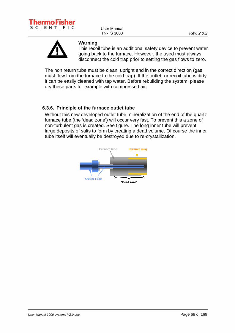
User Manual TN-TS 3000 Rev. 2.0.2
User Manual 3000 systems V2.0.doc Page 68 of 169
Warning This recoil tube is an additional safety device to prevent water going back to the furnace. However, the used must always disconnect the cold trap prior to setting the gas flows to zero.
The non return tube must be clean, upright and in the correct direction (gas must flow from the furnace to the cold trap). If the outlet- or recoil tube is dirty it can be easily cleaned with tap water. Before rebuilding the system, please dry these parts for example with compressed air.
6.3.6. Principle of the furnace outlet tube Without this new developed outlet tube mineralization of the end of the quartz furnace tube (the ‘dead zone’) will occur very fast. To prevent this a zone of non-turbulent gas is created. See figure. The long inner tube will prevent large deposits of salts to form by creating a dead volume. Of course the inner tube itself will eventually be destroyed due to re-crystallization.
Furnace tube
‘Dead zone’
Ceramic inlay
Outlet Tube
Furnace tube
‘Dead zone’
Ceramic inlay
Outlet Tube

User Manual TN-TS 3000 Rev. 2.0.2
User Manual 3000 systems V2.0.doc Page 69 of 169
6.3.7. Cold trap, tubing and filter The cold trap is located in the extra module housing. It is designed to trap water, salts and particles like soot. The trap is filled with water with a low pH. Filling it, can be done with normal tab water acidified with a few drops of a strong acid like sulfuric or phosphoric acid. Filling can easily be done through the small air inlet located on the siphon tube. Optimal level of the liquid in the cold trap is approx. 80% of the lower chamber. The washing liquid is cooled to approx. 4°C to ensure a low partial vapor pressure.
When the system is running fine and the applied method is sufficiently optimized, the liquid level in the cold trap should be more or less stable and small amounts of water will be pushed out. This level can be adjusted by shifting the siphon tube higher or lower (first loosen the red wedge nut). It can be necessary to adjust the height after some time, depending on the pollution of the filter (more pollution, higher pressure, higher siphon tube). Another point that can be adjusted is the gas inlet However, normally this inlet has to be installed just above the bottom of the lower chamber. Make sure, no gas bubbles can escape directly to the overflow siphon. Place a beaker under the overflow tube.
Gas inlet
Gas outlet
Excess water outlet
Cooled water(with Salts andsoot particles)
Air inlet/Fill input
Splash depressor andcooling of gas/vapor
Variable depth
Siphon tube

User Manual TN-TS 3000 Rev. 2.0.2
User Manual 3000 systems V2.0.doc Page 70 of 169
In case an additional detector is connected (for example a CO2 detector (for TOC measurements)), the pressure inside the cold trap can become too high
resulting in constantly pushing out all the water. In this case an alternative for the siphon tube is used. This tube has a little valve. During normal operation, this valve has to be closed. Depending on the number of samples and the injected volume, the cold trap will slowl fill up. Please frequently check the level and when necessary shortly open the valve so, the excess of water is pushed out. Note: The height of this tube does not have to be adjusted like the siphon tube. If the tubing (from the furnace outlet to the cold trap and from the cold trap to the green filter housing) is polluted or wet, disconnect it and wash it with ample water. Dry it with compressed air. Depending on the type of samples, the special paper filter in the green filter housing can be polluted with salts or other deposits. If so, replace the filter according to the instructions in de TN3000 manual supplied with the system.
Warning The deposits on the filter may be toxic.

User Manual TN-TS 3000 Rev. 2.0.2
User Manual 3000 systems V2.0.doc Page 71 of 169
6.4. Several remarks and tips Normally a blank like distilled water will generate a smaller gas volume then a sample containing nitrogen compounds. This can result in less or even no squeezing out of water. When injecting large samples volumes (e.g. > 200 µL), the chance on delayed cooking inside the furnace increases. When delayed cooking occurs the following effects can be generated: Pushing out a lot of liquid from the cold trap Quick cooling of the furnace tube (with an increase chance on destruction of the tube or ceramic inlay. Higher risk of samples getting in direct contact with the quartz components inside the furnace; resulting in a shorter life span. To prevent these problems, the boat program should be made slower for the introduction part. However, this can influence the analytical results. The squeezing out of liquid from the cold trap can occur at any moment during the introduction and analysis. However in most cases it can be observed during the injection of the sample into the boat and during the return of the boat to its home position.
Warning: The deposits on the filter may be toxic. Warning: Salts of Nickel can be toxic. Handle with care. Warning: Sulfuric and phosphoric acid will destroy clothing
and skin.
6.5. Frequent maintenance Daily: Check if the boat and Nickel cylinder is still intact and properly outlined. If not, or in case of any doubt replace it with a new one and clean the furnace tube. Check the liquid level and temperature (is it cold) of the cold trap. When necessary add or drain water. If the cold trap should be totally empty, also add a few drops of a strong acid and check during the first few measurements if the cold trap is not emptied too fast. If this is the case, adjust the height of the siphon/overflow tube. If present, empty the beaker under the overflow tube. Add extra water if the level is too low (less then half the lower chamber). Note: Acidification will not be necessary. Weekly: Clean the cold trap by rinsing it with ample water. Next, fill it to approx. 1 cm below the upper chamber with water and a few drops of concentrated acid like sulfuric or phosphoric acid.

User Manual TN-TS 3000 Rev. 2.0.2
User Manual 3000 systems V2.0.doc Page 72 of 169
Check and if necessary replace the filter in the green filter holder next to the furnace outlet. Clean the outlet tube and the tubing connected of the furnace. Check, and if necessary replace the blue septum in the injection port (Aluminum funnel on top of a red screw).
Keeping the system clean: We strongly advice to measure blanks (i.e. distilled water) frequently. Measure these blanks 3 to 5 times first in a new queue. Also measure some blanks between for example standards and samples. Finally, always measure at least 5 blanks at the end of a queue. If the system is not used for more then a week, measure at least 5 blanks (200~400 µL) prior to setting the system in stand-by mode.
6.6. Trouble shooting Problem: The cold-trap empties when a sample is introduced Solutions: Increase the static height of the exit tube on the cold trap
Decrease the speed of the boat for entering and/or exiting the furnace
Decrease the injection speed of the sample in the boat Decrease the sample volume Another possible reason for this problem can be that the sample is not injected into the boat but into the introduction module. This can be caused by wrong calibration of the boat and/or needle or when the boat is damaged. Problem: The boat is not moving anymore, but the boat drive is. Solutions: Check if the boat is still undamaged. If not, replace it.
If the boat is not damaged, clean the outside of the boat and the inside of the introduction module with water. Beware that the quartz wool does not get too wet. Make sure to dry the parts carefully. Check for blockage inside the furnace tube. Clean if necessary. Note: Do not remove the tube from the furnace unless absolutely necessary. Follow the instructions written above if the tube has to be removed.

User Manual TN-TS 3000 Rev. 2.0.2
User Manual 3000 systems V2.0.doc Page 73 of 169
Problem: Hardly any area is measured or a strange gab in the ‘normal’ peak is seen.
Solution: Most likely the liquid level in the cold trap is too low resulting in leakage of the analysis gasses. Fill the cold trap and, if necessary, adjust the siphon tube.

User Manual TN-TS 3000 Rev. 2.0.2
User Manual 3000 systems V2.0.doc Page 74 of 169
6.7. Flow diagram TN water
Col
dtra
p
NO
Con
verto
r
Tem
p. C
ontr.
Cap
illar
yPMT
dete
ctor
Ozo
ne G
ener
ator
Vac
uum
pum
p
Ozo
ne K
iller
Arg
on
Oxy
gen
Hig
h sa
lt co
mbu
stio
n tu
bew
ith c
eram
ic in
lay
Was
h so
lutio
n

User Manual TN-TS 3000 Rev. 2.0.2
User Manual 3000 systems V2.0.doc Page 75 of 169
7. External samplers
Warning: Always stop the software (ThEuS or ECS) running before switching off the sampler. In not doing so, it can happen that commands are still waiting to be executed while the sampler is switch on again. This can cause malfunctions like a needle crash.
7.1. NeXYZ autosampler The NeXYZ auto sampler replaces the ELS3000 and ELS2100 samplers. Please refer to the User’s Guide of the NeXYZ for installing, maintenance and using instructions.
7.2. ECA1700 AOX Column autosampler This paragraph guides the user through installation and operational procedures, concerning the ECA1700 autosampler. Following these guidelines will explain its function and possibilities. The described procedures are mainly for the “standard” AOX/TOX column method. For other purposes or applications, please refer to the “method sheets” and “application notes”, provided with the unit, whenever applicable.
7.2.1. Introduction-Description The Thermo Fisher Scientific Column sampler model ECA1700 is designed to increase the throughput of the TOX/AOX sample load. In combination with the automatic sample pretreatment units from Thermo Fisher Scientific, a fully automated configuration ensures unattended and trouble free analysis. The autosampler has a 37 position carousel, introducing samples in combination with the ECA-AOX module. For Q.C. purposes, the ECA system software allows control standards, samples and reference samples to be measured during one run. The software handles “multiple point calibration” and the traditional absolute method, which is commonly used with the coulometric technique. Data acquisition, recalculation, reintegration, report generation are just a few features within the software. In short: Both 3000 system and ECA1700 are fully software controlled.

User Manual TN-TS 3000 Rev. 2.0.2
User Manual 3000 systems V2.0.doc Page 76 of 169
ECA1700 autosampler

User Manual TN-TS 3000 Rev. 2.0.2
User Manual 3000 systems V2.0.doc Page 77 of 169
7.2.2. ECA-TOX method, step by step Water samples are run over small columns filled with activated carbon. The ECA1700 carries the pretreated columns in a 37-position carousel. The pre-packed columns placed in the carousel are protected by a cover, which may be purged with Ar or He. The white unused fast connector, found on the 3000 system may be used for this purpose. The purge flow is adjusted with the regular flow meter. After a queue is built/created and the start button is pressed a plunger pushes the carbon plus ceramic wool from the glass column into the sample boat. The carousel moves to the home position and the plunger moves downward, closing the stopper and seal. At this point the module plus furnace tube are gas tight. The boat, which carries the carbon plus ceramic wool, moves into the high temperature combustion zone. The content is oxidized completely and a signal appears on the screen. After combustion, the boat returns to the injection area and a scraper takes out the remaining ashes. The ashes fall into a collection area, which after a full run is emptied, using a vacuum device. In the mean while the boat is being cooled to prepare it for the next sample introduction. When the curve on the screen reaches the baseline again, the analysis may be terminated and the curve is automatically integrated. A result appears on the screen and a printout can be made. In the automatic mode, the next sample is being introduced.
7.2.3. Installation ECA1700 The installation of the ECA1700 is relatively easy. The ECA1700 must be installed on top of the 3000 system. Correct installation procedures and alignments are of great importance. This paragraph will guide you through the installation procedure of the autosampler. The ECA-AOX module, necessary for running samples in combination with the ECA1700, differs in a few details from the standard AOX module. 1) The boat is bigger and has a different shape. 2) There is a scraper in place that cleans the boat from ashes and wool particles as
soon as it returns from the furnace. The remains are collected in a special area, provided underneath the boats home position.
3) A special tube is connected for vacuum cleaning purposes. Connecting it to a vacuum cleaner/device, enables the operator to clean the “remains collective area”. (the size of the area should be sufficient to support a full run, before a cleaning procedure has to be carried out)
4) An “extended boatdriver” package is supplied or mounted onto the 3000 system to control and support the special features of this module.

User Manual TN-TS 3000 Rev. 2.0.2
User Manual 3000 systems V2.0.doc Page 78 of 169
7.2.4. ECA1700, Mounting Unpack the ECA1700 carefully and check all the parts according to the checklist. The Auto sampler size is approximately 330 x 365 x 270 (w x h x d) The ECA1700 should come with:
• A flat cable for communication with the pc • A cover with gas connection to exclude “external” influences • A 37-position carousel • An integrated ID connector (connects to the 3000 system) • 2 Mounting brackets for fixation and positioning (or pre-installed) • An extended boatdriver (in some cases already installed 3000 system) • Extended Module support (in some cases already installed 3000 system) • The special ECA-AOX module • A Column securing-Plunger guide
Check if the mounting brackets are already in place. If not position them as explained in the picture.
Brackets
Brackets

User Manual TN-TS 3000 Rev. 2.0.2
User Manual 3000 systems V2.0.doc Page 79 of 169
Replace the normal boat pusher with the extended one. (mounted on the carriage in the boatdriver, which could be pre-installed)
Extended items
Standard Boat items
Note that the threads of the ECA bracket are pointing outwards! (viewed from the furnace tube) Install the ECA-AOX module, connect the clamp, which joints the furnace tube and the module and insert the oxygen connector. Check if the glass parts are aligned in the correct manner. (see picture next page)

User Manual TN-TS 3000 Rev. 2.0.2
User Manual 3000 systems V2.0.doc Page 80 of 169
Clamp Furnace tube ECA fasteners
Rubber sealing
ECA AOX module
Female Module connector
Safety cover plunger
Column securing and Plunger guide
Fastener ECA
ECA Carousel Position the ECA1700 sampler over the 3000 system, align it with the module and lock the sampler, using the supplied fasteners.

User Manual TN-TS 3000 Rev. 2.0.2
User Manual 3000 systems V2.0.doc Page 81 of 169
7.2.5. ECA1700, external connections
Power cable 3000 system
PC control cable All external connections are found at the backside of the ECA1700. The Power cable coming from the ECA1700 goes into the female module connector on top of the 3000 system. The PC control cable has to be connected onto the ECA1700. The other side of the cable goes onto the specially provided parallel port connection, which (has to be or) is already installed in the external PC. This connector is attached to the IOC2 board. The IOC2-board is usually factory installed in the supplied PC. This board controls the Titration Cell, handles data acquisition and controls the physical movement of the ECA1700.
Electrical Hazard Do not open the cabinet before the power cable is removed.
!!Do not temper with safety features of the ECA1700!!
Warning Wrong connections could lead to malfunction of the analyzer or computer. Only connect or disconnect cables when power is switched off!
Warning Do not temper with- or bypass the safety switch. Operate the ECA1700 with closed access door only. Not complying could result in injury. The column pusher uses excessive force to empty the columns. Stay away from the pusher during operation and keep the access door closed!

User Manual TN-TS 3000 Rev. 2.0.2
User Manual 3000 systems V2.0.doc Page 82 of 169
7.2.6. ECA1700: System and software settings Using the ECA1700 in combination with the 3000 system enables the operator to run unattended analysis. This chapter briefly describes settings and system features for automated sample throughput. Basic settings for the 3000 system in the ECA1700 mode are similar to the “normal” AOX methods. System flows, temperatures and coulometric settings are the same as for AOX according the batch and other manual methods. Differences for ECA configuration are:
• Boat program (number of steps and positioning) • Additional gas flow (Argon outlet used for sample preservation/stability) • In some cases, the analysis time • Optional “2 in 1” analysis • Measuring screen could start before actual sample introduction (optional) • Additional installed hardware
7.2.7. Software settings ECA1700 Typical temperatures are 1000°C for both furnace zones, similar to regular TOX/AOX analysis. Outlet temperature is 300°C Typical gas flows are:
• O2 50mm (combustion/manual flow meter) = 330 mL/min • O2 15mm (bypass/manual flow meter) = 45 mL/min
Depending on the specific application the fan will start cooling at maximum capacity (100%) as soon as the boat returns. The duration of cooling is approximately 4 minutes. Before the next sample gets introduced, the cooling will have to be shut down or reduced to 10%. Check if this setting is correct in the “Analysis method” window.
“Normal cooling” is 10% “Forced cooling” is 100% Beside standard methods, customized method can be made and stored.
• Open a specific analysis method. • Save it under a different name. • Modify the necessary items. (boat program, temperatures etc) • Close the window again. • Go to the controller window and select the new method.

User Manual TN-TS 3000 Rev. 2.0.2
User Manual 3000 systems V2.0.doc Page 83 of 169
Basic boat program, used with current ECA application:
No Name Position Speed Pause 1 Standby 50 mm 15 mm/s 100 s2 Evaporation 90 mm 5 mm/s 60 s 3 Combustion 175 mm 5 mm/s 180 s4 Home 0 mm 10 mm/s 240 s
For more details, refer to the electronic manual in ThEuS. Note: The cooling time must be programmed in step 4. This is the “Home” position of the boat-program. This step controls the cooling time before the next sample is introduced. Not doing so will affect the next result because of too high temperature in the entrance zone.

User Manual TN-TS 3000 Rev. 2.0.2
User Manual 3000 systems V2.0.doc Page 84 of 169
7.3. ESA2000 AOX and Solids auto sampler This paragraph guides the user through installation and operational procedures, concerning the ESA2000 auto sampler. Following these guidelines will explain its function and possibilities. The described procedures are mainly for the “standard” methods. For other purposes or applications, please refer to the “method sheets” or “application notes”, provided with the unit, whenever applicable.
Figure: 3000 system with ESA2000
7.3.1. Introduction-Description The Thermo Fisher Scientific AOX-Solid auto sampler model ESA2000, is designed to increase the throughput of the sample load. In combination with the 3000 system, unattended and trouble free analysis are a reality. The auto sampler has a 48 position carousel, introducing the samples in combination with the special sample cups, made from quartz glass or metal. A laser beam controls the in- and out coming sample cups, to make sure that there is no pile up in the furnace tube or module. For Q.C. purposes, the ESA system software allows control standards, samples and reference samples to be measured during a run. The software handles “multiple point calibration” as well as the traditional “absolute method”, which is commonly used with the coulometric technique. Data acquisition, recalculation, reintegration, report generation are just a few features within the software. In short: Both 3000 system and ESA2000 are fully software controlled.

User Manual TN-TS 3000 Rev. 2.0.2
User Manual 3000 systems V2.0.doc Page 85 of 169
Figure: ESA2000
7.3.2. ESA-AOX batch method, step by step Water samples are put in a conical flask and approximately 50 mg of activated carbon is added. The substance shakes for one hour and is filtrated over the Thermo Fisher Scientific Frit. The Frit is a sample cup, which has a quartz-sintered filter layer, capable of the separation between the water phase and the activated carbon. The prepared Quartz Frits are placed on the carousel and protected by a cover, which may be purged with Ar or He. The white unused fast connector, found on the 3000 system may be used for this purpose. The purge flow is adjusted with the regular flow meter. After a queue is listed and the start button is pressed the arm-hand lifts a Frit or sample-cup from the carousel and puts it into the ESA module on top of the boat. The grabber-hand has a neoprene sealing ring, which closes the entry of the module, creating a gas-tight environment. The boat, which carries the Frit plus carbon, moves into the high temperature combustion zone. The content is oxidized completely and a signal appears on the screen. After combustion, the boat returns to the injection area and the Frit or sample-cup is taken out and placed onto the carousel again. A laser beam is used to check if the sample cups placed in the module are taken out as well. An error message will appear and prompts the operator to take corrective action. (frit detected yes/no) The laser control will prevent pile-up and malfunction. In the mean while, the boat is being cooled as soon as the boat starts to retract. The cooling action is necessary to lower the temperature of the boat and module, prior to the next sample introduction. As soon as the curve on the screen reaches the baseline again and maximum analysis time is reached, the analysis may be terminated and the curve is automatically integrated and stored. The result appears on the screen and a printout can be made. In the automatic mode, the next sample is being introduced.

User Manual TN-TS 3000 Rev. 2.0.2
User Manual 3000 systems V2.0.doc Page 86 of 169
7.3.3. General solids method, step by step Solid samples, highly viscous samples, high boiling ones, are usually run with the ESA2000. This will definitely improve repeatability and sample throughput. Instead of the “Frit” used for the AOX batch method, described in the previous chapter, a smaller type sample cup is used. The ESA2000 is slightly modified with a smaller grabber and the “solids module” carries a smaller boat. The sample cups are placed on the carousel and protected by a cover, which may be purged with Ar or He. The small flow regulator found on the ESA2000 may be used for this purpose. An indicator existing of LED’s shows the amount of flow purged over the samples. The carousel in standard configuration supports the “AOX Frit” only. For the use of the smaller cups, small inlays are placed for proper positioning. Next a queue is listed and the start button is pressed the arm-hand lifts a Frit or sample-cup from the carousel and puts it into the ESA module on top of the boat. The grabber-hand has a neoprene sealing ring, which closes the entry of the module, creating a gas-tight environment. The boat, which carries the sample cup with content, moves into the high temperature combustion zone. The content is oxidized completely and a signal appears on the screen. After combustion, the boat returns to the injection area and the sample-cup is taken out and placed onto the carousel again. A laser beam is used to check if the sample cups placed in the module are taken out as well. An error message will appear and prompts the operator to take corrective action. (cup/crucible detected yes/no) The laser control will prevent pile-up and malfunction. In the mean while, the boat is being cooled as soon as the boat starts to retract. The cooling action is necessary to lower the temperature of the boat and module, prior to the next sample introduction. As soon as the curve on the screen reaches the baseline again and maximum analysis time is reached, the analysis may be terminated and the curve is automatically integrated and stored. The result appears on the screen and a printout can be made. In the automatic mode, the next sample is being introduced.

User Manual TN-TS 3000 Rev. 2.0.2
User Manual 3000 systems V2.0.doc Page 87 of 169
7.3.4. Installation of the ESA2000 The installation of the ESA2000 is relatively easy. The ESA2000 must be installed on top of the 3000 system, using a special “docking station”. Correct installation procedures and alignments are of great importance. This paragraph will guide you through the installation procedure of the autosampler. The ESA-AOX module, necessary for running samples in combination with the ESA2000, differs in a few details from the standard AOX module. 1. The boat used is a special ESA-AOX- or Solids-version to support the different
sample cups and “Frits”. 2. The sample entrance in the module does not have a conical joint for stopper
purposes. (the neoprene ring just seals off on the edge of the glass) 3. A “module positioning” package is supplied or mounted onto the 3000 system to
control and support the special features of this module. It enables both positioning and fixation.
7.3.5. ESA2000, Mounting Unpack the ESA2000 carefully and check all the parts according to the checklist. The autosampler should come with the following items:
• A flat-cable for communication • A carousel cover to exclude “external” influences • A 48-position carousel • Mounting brackets for fixation and positioning of the boat module (or pre-
installed) • Docking-station for ESA positioning (fast removal, positioning) • The special ESA-AOX module • Power cord
Mounting brackets
Docking-station
Fastener Base plate gas and ID Connector in standard position
Figure: Front-view Docking-station

User Manual TN-TS 3000 Rev. 2.0.2
User Manual 3000 systems V2.0.doc Page 88 of 169
Check if the mounting bracket for the Docking-station is already in place. If not position it as showed in the picture. Verify if the base plate including gas connections and ID connector is repositioned in a way as the picture below.
Base plate re-positioned for easier ID and gas connector access. If it is not re-positioned the ESA2000 will hit the connectors once placed on top of the docking station
Figure: Re-positioned base plate for connectors
Mounting bracket ESA Positioning ESA
Figure: Mounting brackets, positioning

User Manual TN-TS 3000 Rev. 2.0.2
User Manual 3000 systems V2.0.doc Page 89 of 169
Spring
Rear- end support
Teflon boat positioning
Fastener Boat positioner
Figure: right-hand side view 3000 system The boat positioner is used to adjust the home position of the returning boat. The exact home position is important for the ESA hand. The hand is adjusted with both soft- and hardware. The magnet, which controls the movement of the boat, has some tolerance in the positioning. In order to take away this tolerance, a “mechanical home” position is created. An adjustable plastic thread is used to dictate the maximum allowed distance. The boat can not travel beyond this point and all tolerance is taken out of the motion.
ESA Module
ESA position lock Boat Magnet
Teflon Boat positioning
Adjustment screws ESA position lock
Figure: helicopter view module positioning

User Manual TN-TS 3000 Rev. 2.0.2
User Manual 3000 systems V2.0.doc Page 90 of 169
7.3.6. ESA2000 hardware alignment procedure For correct alignment, please follow this procedure.
1. Check if all brackets, docking station and accessories are correctly mounted and secured.
2. Install the ESA boat module including the boat, position and align the module.
3. Secure the module, using the “Plate rear-end support” 4. Check if boat drive is “home” (metal arrow point at zero) 5. Adjust the plastic thread, until the boat is in the exact center of the “module
sample inlet”. 6. Loosen the “ESA position lock Adjustment screws” and carefully place the
ESA2000 on top of the “ESA docking station” 7. Remove the “neoprene sealing ring” from the arm-hand 8. With the power switched off, manually move the arm-hand to the sample
inlet. 9. Lower the hand until the hand is just above the boat (2-3 mm) 10. Observe if the spacing between the sample inlet and the ESA 2000 hand
is equally divided (left and right). If not, move the ESA until the desired position is reached.
11. Carefully remove the ESA and tighten the “ESA position lock Adjustment screws”. Reposition the ESA and check if alignment is still ok.
• Verify points 7-11 by the pictures on the next page.

User Manual TN-TS 3000 Rev. 2.0.2
User Manual 3000 systems V2.0.doc Page 91 of 169
Neoprene ring present Neoprene ring removed (point 7)
Center hand/arm Positioned above the inlet (point 8) Lowered completely (points 9+10)
This takes care of the “hardware alignment” for the 3000 system ESA2000 configuration. Besides this procedure a “software calibration” must be carried out. This procedure is explained in the software part of this chapter.

User Manual TN-TS 3000 Rev. 2.0.2
User Manual 3000 systems V2.0.doc Page 92 of 169
7.3.7. ESA2000 external connections
Power cord connector, On-off switch
Purge gas connection
Flat-cable connector
ESA2000 rear-view All external connections are found at the backside of the ESA2000. The female connector on top of the 3000 system is left empty. The flat-cable has to be connected at the back of the ESA2000. The other side of the cable goes onto the specially provided flat-cable connection, which (has to be or) is already installed in the external PC. This connector is attached to the IOC2 board. The IOC2-board is usually factory installed in the supplied PC. This board controls the Titration Cell, handles data acquisition and controls the physical movement of the ESA2000.
Electrical Hazard Do not open the cabinet before the power cable is removed.
!!Do not temper with safety features of the ESA2000!!
Warning Wrong connections could lead to malfunction of the analyzer or computer. Only connect or disconnect cables when power is switched off!

User Manual TN-TS 3000 Rev. 2.0.2
User Manual 3000 systems V2.0.doc Page 93 of 169
Warning Do not temper with- or modify the laser settings or adjustment. Laser light can be a threat to your eyesight. Even though the intensity is not of a high level, do not look directly into the beam. Operate the ESA2000 with supplied cover only. Not complying could result in injury. Readjustments should be carried out by trained Thermo Fisher Scientific technicians only!
7.3.8. ESA2000: System and software settings Using the ESA2000 in combination with the 3000 system enables the operator to run unattended analysis. This chapter briefly describes settings and system features for automated sample throughput. With the hardware alignment carried out correctly, the next step, “software alignment must be carried out. This is very important with first time installation or re-calibration, in case of erratic functioning. The following steps will guide you through the procedure. Basic settings for the 3000 system in the ESA2000 mode are similar for the “normal” AOX methods. System flows, temperatures and coulometric settings are the same as for AOX, according the batch and other manual methods. However, for solid methods refer to application notes or reports, for correct settings. Features and Differences for the ESA configuration are:
• Boat program (number of steps and positioning depending on application) • Additional gas flow (Argon outlet used for sample preservation/stability) • In some cases, the analysis time • Software calibration protocol. • Laser control for sampling. • One special ESA boat module for AOX and one for Solids in general. • ESA2000 supports the special Thermo Fisher Scientific Frits. • 2 sizes of sample cups, for different analytical purposes. (1 AOX cups or
Frits for the ESA-AOX module. 2 Solids sample cups for the ESA solids module.)
• Measuring screen can start before actual sample introduction (optional in extra window)
• Additional installed hardware

User Manual TN-TS 3000 Rev. 2.0.2
User Manual 3000 systems V2.0.doc Page 94 of 169
7.3.9. Software settings ESA2000
Special Attention Before the power is switched on, move the arm into a “neutral position”. Manually move the arm in the approximate center of the “left-right, up-down” position.
When the ESA is positioned in the Docking-station the arm should be positioned into the approximate center of the unit. (check the above “special attention”) Pressing the “Init” button with the power supplied and data cable connected to the ESA2000 and a powered 3000 system, should activate the “Arm-hand” and sample carousel. They both are now moving to their home positions and perform the initialization procedure. The ESA checks if position 48 is empty. If this is confirmed it checks if there is no sample cup left in the boat. If one is found, the ESA picks it up and places it on position 48. The system will produce a message to the screen, prompting the user to remove it from 48. Always check if position 48 is empty. This will save analysis time! For first time operation a calibration procedure has to be carried out, for optimal performance. Sensors inside the ESA2000 should be positioned correctly. This is normally carried out in the factory. In case of doubt about the precision of sensor positioning, contact a Thermo Fisher Scientific representative to correct and/or assist with this procedure in case of readjustment.
Warning Do not temper with the laser beam or it’s adjustment! This must be carried out by a trained Thermo Fisher Scientific representative.
Direct Sample positioning is also possible. Just key-in a number in the “Sample Position” window. (1-48) Pressing “Enter” on the keyboard will trigger the action and moves the carousel to the desired position. Note: Movement of stepper motors can be “noisy and/or irregular” when data traffic on the PC gets heavier or initialization is carried out. This should not affect the sample handling.

User Manual TN-TS 3000 Rev. 2.0.2
User Manual 3000 systems V2.0.doc Page 95 of 169
Two parameters should be checked and adjusted for: 1. To check if this procedure is correct, close the bypass gas flow (only for this
specific test) and reduce the oxygen carrier to approximately 10 mm (manual flow meters) or 25 mL/min for mass flow meters. Observe the Sulfuric acid in the scrubber and check for bubbles. If there are no bubbles appearing in the acid, increase the number of steps, to get more pressure on the sealing between the rubber and the glass wall. If necessary, repeat the procedure until a gas tight sealing is reached.
Warning Do not forget to restore the original flow settings! Sulfuric Acid could be redirected towards the furnace!
2. Another parameter to be checked is the positioning of the sample cup. Check if
the cup is freely placed onto the boat without added pressure from the hand. This could create damage to the boat or sample cup after repeated action. Closely observe the sample cup upon positioning onto the carousel. Check if it is freely positioned without added pressure or a “free-fall” onto the carousel. Correct positioning is necessary to prevent sample spill out of the cups during positioning or damage to the hand.
Warning Prevent the hand from crashing onto the carousel. The alignment or mechanical features of the stainless steel hand may be lost, because of mechanical damage.

User Manual TN-TS 3000 Rev. 2.0.2
User Manual 3000 systems V2.0.doc Page 96 of 169
7.3.10. ESA Boat program and related settings A special boat program is needed for the execution of the AOX batch method. The following settings will have to be checked and if not present, they have to be programmed. The Standard method is: ESA AOX or ESA solids. Depending on the specific application the fan will start cooling at maximum capacity (100%) as soon as the boat returns. The duration of cooling is approximately 4 minutes. Before the next sample gets introduced, the cooling will have to be shut down or reduced to 10%. Check if this setting is correct in the “Analysis method” window.
“Normal cooling” is 10% “Forced cooling” is 100%
For some applications a continuous maximum cooling is standardized. Typical temperatures are 1000°C for both furnace zones, similar to regular TOX/AOX analysis. Outlet temperature for scrubber heating is 300°C Typical flows for the applications are:
• O2 50mm (combustion/manual flow meter) = 330 mL/min • O2 15mm (bypass/manual flow meter) = 45 mL/min
Beside standard methods, customized method can be created and stored.
• Open a specific method. • Save it under a different name. • Modify the necessary items. (boat program, temperatures etc) • Close the window again. • Go to the controller window and select the new method.
Basic boat program, used with current ESA-AOX batch application:
No Name Position Speed Pause 1 Standby 0 mm 10 mm/s 0 s2 Evaporation 70 mm 5 mm/s 60 s 3 Combustion 180 mm 5 mm/s 180-240 s4 Home 0 mm 10 mm/s 0 s

User Manual TN-TS 3000 Rev. 2.0.2
User Manual 3000 systems V2.0.doc Page 97 of 169
Example of a special boat program, used with a specific ESA-solids application:
No Name Position Speed Pause 1 Standby 0 mm 10 mm/s 0 s2 Position1 60 mm 5 mm/s 60 s 3 Position2 75 mm 2 mm/s 60 s4 Position3 100 mm 2 mm/s 30 s5 Position4 150 mm 5 mm/s 120 s6 Home 0 mm 10 mm/s 0 s
For more details, refer to the Software manual or the Thermo Fisher Scientific web-site: www.thermo.com

User Manual TN-TS 3000 Rev. 2.0.2
User Manual 3000 systems V2.0.doc Page 98 of 169
8. Coulometric analysis on the 3000 SYSTEM (optional)
8.1. Introduction 3000 SYSTEM in Halogen/Sulfur mode The 3000 SYSTEM optional, can be upgraded with a “titration package” for the fast and efficient analysis of organic halogen (X) and sulfur (S) compounds. The 3000 SYSTEM provides for the use of different modules, which can be used for the incineration of samples in a furnace. The hydrogen halides or the sulfur dioxide in the incineration products are then coulometrically titrated in an automated microtitration cell. This coulometric system is based on the KIWA-principle. (KIWA is the Royal Dutch Waterworks) The analysis is an absolute measurement, so no calibration is needed. The flowchart for the measurement is as follows:
Fig. Schematic explanation of coulometric detection

User Manual TN-TS 3000 Rev. 2.0.2
User Manual 3000 systems V2.0.doc Page 99 of 169
8.2. Principle of the measurements With an introduction mechanism using a boat driver or injection syringe, the sample is introduced into the furnace. During the movement into the furnace the sample is flushed with argon. The volatile components are transported directly into the furnace. In the furnace the sample oxidizes with O2. The gas flow is carried through a heated connection to the scrubber. Here the water is removed from the gas. After the scrubber, the gas is led to the NOx-scrubber. Then the gas flows into the titration cell, where the actual reaction takes place. (silver-ions Ag+ react with halide-ions X- ) A signal appears on the PC screen and the area generated by this signal is integrated. The program calculates the actual concentration and stores the result.
8.3. Sample introduction The modularity of the 3000 SYSTEM consists of three different types of titration cells (halogen, sulfur large volume, sulfur small volume) and four methods of sample introduction. For most of the applications there are two ways for sample introduction: manually or with an auto ampler.
8.3.1. Manual sampling modules In total there are four introduction modules for the 3000 SYSTEM. Each of them has it own purpose. The design of the introduction modules is based on current standard analytical methods for organic halogen and sulfur compounds. The introduction modules are easily interchangeable and after installation fully controlled using the Thermo Fisher Scientific software. The four introduction modules are: 1. AOX-module 2. POX-module 3. Solids module (described in chapter 3.5.3 ) 4. Liquids module (described in chapter 3.5.2 and 3.5.1 ) The principles of the design of the modules are based on the requirements for the standard analyses of organic halogen and sulfur compound/content in samples of a divergent nature and origin. Various fractions of organic halogen (X) and sulfur (S) compounds are analyzed by these standard analytical methods. The modules can also be used for non-standard analyses.

User Manual TN-TS 3000 Rev. 2.0.2
User Manual 3000 systems V2.0.doc Page 100 of 169
8.3.1.1. AOX module The AOX module is used for Adsorbable Organic Halogen (AOX). The sample is adsorbed onto activated charcoal in the preparatory phase. The charcoal bearing the adsorbed analytical sample is slid into the furnace on a boat and burned in a flow of oxygen. With this module also Total Organic Halogen (TOX) can be analyzed.
Warning Do not use this introduction module for samples containing significant quantities of (combustible) organic components, like oil, waxes etc.. The sample is introduced in a flow of pure oxygen. Any combustible component will ignite prematurely.
8.3.1.2. POX module The POX module is used for Purgable Organic Halogen (POX). In this module volatile organic halogen compounds are purged from an aqueous solution by means of argon gas. The analysis sample is first mixed with oxygen before being blown directly into the furnace. The POX Module is used in conjunction with the AOX module.
8.3.1.3. Solids Module The solids module is used for analysis of Total halogen (TX) or Total sulfur (TS) content in solid samples. The module is meant for the analysis of halogen and sulfur compounds in solid samples and liquids containing large molecular compounds with boiling temperatures above 450°C. These are carried into the furnace by a flow of argon and burned in oxygen.

User Manual TN-TS 3000 Rev. 2.0.2
User Manual 3000 systems V2.0.doc Page 101 of 169
8.3.1.4. Liquid Module The liquid module is used for analysis of extractable organic halogen (EOX) and Extractable organic sulfur (EOS). This module permits the injection of solutions of halogen or sulfur compounds in organic solvents, for example after being extracted. The injected sample is then carried by a flow of argon into the furnace and burned in oxygen. With this module also Total halogen (TXliquid) or Total sulfur (TSliquid) in liquid samples and Total halogen (TXgas) or Total sulfur (TSgas) in gas samples can be analyzed.

User Manual TN-TS 3000 Rev. 2.0.2
User Manual 3000 systems V2.0.doc Page 102 of 169
8.3.2. Auto sampling To extend the throughput of the samples Thermo Fisher Scientific has developed a number of auto samplers for use with the 3000 SYSTEM. One of them is used for AOX-sampling: ECA1700. This unit automatically dispenses the carbon into the introduction module. More than 35 (!) samples can be analyzed in one run. Another one is used for TS/TX Liquid sampling: The ELS3000. More than 70 (!) samples can be analyzed in one run. (refer to chapter 7)
8.4. Furnace The sample is placed in a boat in a stream of oxygen and/or argon into the furnace. The furnace is divided into two temperature zones. (according ASTM guidelines) The temperature in each zone can be individually adjusted to all temperatures up to 1100°C. The sample incineration time in each zone can also be adjusted. In the furnace the sample is oxidized into gas. In the event of incomplete incineration soot deposits may be formed. (refer to chapter 13 “trouble shooting”)
8.5. Gas conditioning The incineration gases leave the furnace via a glass gas exhaust tube or outlet, through which the sample is led to the scrubber. The outlet is maintained at a high temperature by means of a heating wire in order to prevent condensation and trap other “undesired components”. An oxygen bypass is placed in the outlet to prevent a back flash of sulfuric acid towards the furnace. With a needle valve the amount of oxygen led through the bypass can be regulated. After this scrubber the gas is led to the next scrubber, the so-called NOx-scrubber (mainly used for AOX and Cl analysis).
8.6. Detector, coulometric titration After the gas conditioning the sample gas will be detected in the titration cell. Three different titration cells can be used. These are: a cell for the coulometric silver titration of halides, a cell for the iodometric analysis of sulfur dioxide at p.p.m. level, and a cell for the iodometric analysis of sulfur dioxide at p.p.b. level. After preparation and installation, the titration cells are suitable for long series of automatic analyses. The signals from the titration cell go directly to the IOC-board in the computer, where the data is collected and processed.

User Manual TN-TS 3000 Rev. 2.0.2
User Manual 3000 systems V2.0.doc Page 103 of 169
8.6.1. Halide analysis, principle Ei-r is governed by the concentration of silver ions in solution as stated by Nernst's Law. A change in the concentration of silver ions will therefore give rise to a change in Ei-r. The concentration of silver ions changes when halide ions enter the solution. The halide ions tend to remove silver ions from the solution by the formation of silver halides, which are notoriously insoluble. This can for example occur by the reaction:
Ag+
(aq) + Cl-(aq) --> AgCl(s)
When Ei-r changes, the coulometer passes current (1) through the generator circuit, thus forming silver ions at the anode. Hydrogen is then formed at the cathode. The silver ions react with halide ions until these have disappeared or, in other words, until the concentration of silver ions has returned to the same level as the initial concentration of roughly 10-7 M. The solubility product indicates the relationship between the concentrations of silver ions and halide ions in a saturated solution. For silver chloride this is:
Ks = [Ag+][CI-] = 1.78 x 10⁻¹⁰ As long as Ei-r continues to change current will pass through the generator circuit and silver ions will be generated. As Ei-r approaches its initial potential the current will fall off. Once Ei-r has reached its initial value again, i.e. when all the halide ions have been converted, the generator curve (1) will again be zero. There is a difference in potential between anode and cathode of:
Ei-r + Ebias Ebias is a fixed potential of -0.315 V that serves, among other things to compensate the electrical resistance of the cell. The total of Ei-r + Ebias is equal to about 0.5 V. Coulometry is a form of titration. The substance to be titrated is converted by means of an electrical charge. It should therefore be remembered that it is not the substance itself, which is being titrated but an electrical charge. The figure below shows an 3000 SYSTEM titration curve. At first the current increases. The speed with which this takes place depends on the speed with which the hydrogen halides enter the titration cell, or in other words the way in which the analysis sample is introduced. After reaching a peak the current strength returns to zero. (speed of titration depends on gain and Cell condition, see figure next page)

User Manual TN-TS 3000 Rev. 2.0.2
User Manual 3000 systems V2.0.doc Page 104 of 169
example titration curve
The quantity of Ag+ ions which is generated by the flow of the current through the cell and consequently the quantity of deposited halide ions, behave in accordance with Faraday's Law:
mn f
I dtQ
n f
t
= =∫1
0..
.
where: Q = the quantity of charge in Coulomb passing through the electrode surface in time t.
m = mass of converted substance [mol] F = Faraday's constant (96487 C/mol) n = number of electrons involved in the electrode reaction (here n = 1) t = titration time I = current (as a function of time)
Integrating the current over time provides the quantity of charge used for titrating the halide. The quantity of charge, which has been titrated is shown in µC in the right hand column in the measurement display. The quantity of halide present in the cell can then be calculated from this figure. The calculations are carried out automatically by the Thermo Fisher Scientific 3000 SYSTEM software.

User Manual TN-TS 3000 Rev. 2.0.2
User Manual 3000 systems V2.0.doc Page 105 of 169
8.6.1.1. Halide analysis, titration cell The titration cell consists of the parts shown in the picture below.
Where: I = Indicator eIectrode (Ag)
R = Reference electrode (3M KCl saturated with AgCl) A = Anode (Ag) C = Cathode (Pt)
The cathode is contained in a glass tube, and is separated from the measurement solution by means of a frit. The purpose of this frit is to exclude the effect of disruptive reactions around this electrode. 0 = Outlet G = Gas inlet tube
Acid The titration cell contains a solution of 75% acetic acid in water. The concentration of silver ions in solution is maintained at a constant level of about 10-7 M.

User Manual TN-TS 3000 Rev. 2.0.2
User Manual 3000 systems V2.0.doc Page 106 of 169
8.6.1.2. Halide analysis, circuit diagram The figure below shows a general and simplified diagram of the electrical circuit.
Where: V = Voltmeter
Amp = Ammeter RΩ = Variable resistance R = Reference electrode I = Indicator electrode A = Anode C = Cathode
The titration cell contains two pairs of electrodes: Measuring path: - Indicator electrode I (silver) - Reference electrode R (silver/silver chloride). This electrode is connected to the
solution through a bundle of capillary tubes. Generation path: - Anode A (silver) - Cathode C (platinum) The coulometer consists of a combination of two circuits: The measuring circuit - Here the difference in potential Er-i, between the indicator and
reference electrodes is measured. The generator circuit - When there is a change in Er-i, the coulometer passes a
current through the anode/cathode circuit. Ag, ions are generated at the anode as a result.
Acid The titration cell contains a solution of 75% acetic acid in water. The concentration of silver ions in solution is maintained at a constant level of about 10-7 M.

User Manual TN-TS 3000 Rev. 2.0.2
User Manual 3000 systems V2.0.doc Page 107 of 169
8.6.2. Sulfur analysis, principle Ei-r is governed by the concentration of iodine ions (I3-) in the electrolyte and in the side leg containing the reference electrode. The concentration of I- in the side leg containing the reference electrode remains constant. A change in the concentration of I- in the electrolyte will thus result in a change in Ei-r. The concentration of I3- changes when sulfur dioxide dissolves in the electrolyte. Sulfur dioxide reacts with I3- as follows:
SO2 + I3--+ 6 H20 ------ > SO42- + 3 I- + 4 H3O+
When Ei-r changes the coulometer passes current (1) through the generator circuit. This results in the conversion of I- into I2 at the platinum anode, followed by the formation of I3- as indicated below:
2 I- -------- > I2 + 2e
I2 + I- --------- > I3- This process will continue until Ei-r no longer changes, i.e. until the concentration of I3- has returned to the value it had before the addition of S02. The generator current will then be equal to zero and all the S02 will have been converted into sulfate. Here too the difference in potential between anode and cathode of: Ei-r + Ebias = about 0.5 V Ebias is in this case equal to + 0.145 V The quantity of I- converted can be calculated from the charge needed for the conversion. Then the quantity of S02 present in the cell can be determined according to Faraday's Law. The same remarks apply here to the titration curve as were made with respect to halide analysis.

User Manual TN-TS 3000 Rev. 2.0.2
User Manual 3000 systems V2.0.doc Page 108 of 169
8.6.2.1. Sulfur analysis, titration cell The titration cell consists of the parts shown in the picture below.
Where: I = Indicator electrode (Pt spiral wound) R = Reference electrode (Pt/l2/l-) A = Anode (Pt spiral wound) C = Cathode (Pt)
The cathode is contained in a separate compartment connected to the cell via a narrow passage.
G= Gas inlet tube
Acid The titration cell contains a solution of 0.1% KI, 0.1% NaN3 and 0.5 % acetic acid in deionized water. The NaN3 (sodium azide) is added to prevent possible disturbances to the measurement caused by nitrous oxides forming in the cell.
Warning Sodium Azide is extremely toxic. Read the instructions of the chemical safety sheet carefully and handle accordingly!

User Manual TN-TS 3000 Rev. 2.0.2
User Manual 3000 systems V2.0.doc Page 109 of 169
8.6.2.2. Sulfur analysis, circuit diagram The figure below shows a general and simplified diagram of the electrical circuit.
Where: V = Voltmeter
Amp = Ammeter RΩ = Variable resistance R = Reference electrode I = Indicator electrode A = Anode C = Cathode
The titration cell contains two pairs of electrodes: Measuring path: - Indicator electrode I (platium) - Reference electrode R (platinum/I2I-). This electrode is connected to the solution
through a bundle of capillary tubes. The actual electrode is a platinum wire. This is placed in an electrolytic solution containing solid I2.
Generation path: - Anode A (platinum) - Cathode C (platinum) The coulometer consists of a combination of two circuits: The measuring circuit - Here the difference in potential E, between the indicator and reference electrodes is measured. The generator circuit - When there is a change in El-R the coulometer passes a current through the anode/cathode circuit. I- ion is converted into I2, at the anode as a result.

User Manual TN-TS 3000 Rev. 2.0.2
User Manual 3000 systems V2.0.doc Page 110 of 169
Acid The titration cell contains a solution of 0.1% KI, 0.1% NaN3 and 0.5 % acetic acid in deionized water. The NaN3 (sodium azide) is added to prevent possible disturbances to the measurement caused by nitrous oxides forming in the cell.
8.7. Data processing The Thermo Fisher Scientific software controls the analyzer and all analysis, using a separate PC. Several values can be set e.g. furnace temperature. Boat movement and injection speed can be programmed as well as length of the analysis. Besides control and programming, the software processes the detector signal and calculates the concentration. The results and graphics can be printed. For further information see the Thermo Fisher Scientific software manual for 3000 SYSTEM-systems.

User Manual TN-TS 3000 Rev. 2.0.2
User Manual 3000 systems V2.0.doc Page 111 of 169
9. INSTALLATION HALOGEN AND SULFUR OPTION (coulometric)
9.1.1. Glassware connections Glassware is the most important fact of the Thermo Fisher Scientific analyzers. Connected to each other all parts form the heart of the analyzer. Therefore it is very important to connect the parts carefully. Leakage has to be excluded. The glassware parts are: 1. Sample introduction module 2. Furnace tube 3. Connection tube furnace scrubber 4. Sulfuric acid scrubber 5. Splash trap 6. NOx-scrubber 7. Titration cell In the next paragraphs all connections will be discussed.
9.1.2. Sample introduction module In total there are four introduction modules for the 3000 SYSTEM. Each of them has to be installed differently. The introduction modules are easily interchangeable. The four introduction modules are: 1. AOX-module 2. POX-module 3. Solids module 4. Liquids module
9.1.2.1. AOX module The AOX module has to be slide into the furnace tube. Be sure the white Teflon magnet in the boat module is installed just above the white Teflon boat driver. This is a magnetic connection. Connect the gas connector (O2: Blue on blue). Place the clamps in the right position. Place AOX ID-connector.
Warning Do not use this introduction module for samples containing significant quantities of (combustible) organic components, like oil, waxes etc.. The sample is introduced in a flow of pure oxygen. Any combustible component will ignite prematurely.

User Manual TN-TS 3000 Rev. 2.0.2
User Manual 3000 systems V2.0.doc Page 112 of 169
9.1.2.2. POX module The POX module has to be placed up the boat driver part of the 3000 SYSTEM. The glass outlet of the module can be connected directly to the furnace tube. Place the clamps in the right position. If an AOX module is already installed, a special glass outlet can be used to place on the inlet of the AOX-module. Connect the gas connectors (O2: Blue on blue, Ar: White on White). Place the clamps in the right position. Place POX ID-connector.
9.1.2.3. Solids Module The solids module has to be slide into the furnace tube. Be sure the white Teflon magnet in the boat module is installed just above the white Teflon boat driver. This is a magnetic connection. Connect the gas connectors (O2: Blue on blue, Ar: White on White). Place the clamps in the right position. Place SOL ID-connector.
9.1.2.4. Liquid Module The liquid module has to be placed in the boat driver part of the 3000 SYSTEM and slide into the furnace tube. Connect the gas connector (O2: Blue on blue). Place the clamps in the right position. Place LIQ ID-connector.
9.1.3. Furnace tube The quartz furnace tube has to be sliced into the furnace compartment with the narrow end towards the outlet side.
Special Attention Avoid touching the surface of the furnace tube with your bare fingers. The traces of grease left by your fingertips will create hotspots and reduce the service life of the furnace tube.
9.1.4. Connection tube furnace scrubber The heated connection tube is the connection between the furnace tube outlet and the sulfuric acid scrubber. Follow the next steps for installing the tube.
The furnace tube and outlet become very hot during the operation of the 3000 SYSTEM. Carelessness may result in burns.
9.1.5. Installation sulfuric acid scrubber To place and connect the scrubber you have to be sure a clean and dry drip tray (F) is placed in the scrubber department. Check that both stopcocks are closed (handle in horizontal position). Follow the next steps for proper installation. 1. Remove the Permapure scrubber and install the stainless steel bracket. (A) 2. Suspend the scrubber on the bracket. (B) 3. Place the “connection furnace scrubber”. (C)

User Manual TN-TS 3000 Rev. 2.0.2
User Manual 3000 systems V2.0.doc Page 113 of 169
4. Connect the inlet of the scrubber to the outlet of the heated connecting tube (ball-joint), using clamp no. 12. (D)
5. Insert the connector (electrical) into the socket. (E) 6. Adjust the temperature of the outlet. (typical 300°C) 7. Adjust the gasses and fill the scrubber with sulfuric acid.
9.1.6. Sulfuric acid scrubber connected
Figure: sulfuric acid scrubber assembly
9.1.7. NOx-scrubber Sometimes it is necessary to use a NOx-scrubber. Make sure that a clean and dry drip tray is placed in the “Cell compartment”. The NOx-scrubber is connected directly onto the gas inlet of the titration cell. Follow the next steps for installing the scrubber: 1. Fill the scrubber with sulfuric acid up to the marker 2. Place the NOx-scrubber. 3. Connect the outlet of the NOx-scrubber onto the gas inlet, using clamp no. 12. 4. Connect the tubing coming from the outlet of the scrubber onto the inlet of the
NOx-scrubber.
A
B
C
D
E
F

User Manual TN-TS 3000 Rev. 2.0.2
User Manual 3000 systems V2.0.doc Page 114 of 169
9.1.8. Detector, titration cell To place and connect the titration cell be sure a clean and dry drip tray is placed in the detector department. See the next picture for the cell configurations.
Follow the next steps for installing the titration cell. 1. Place stirring motor 2. Connector 5-pole DIN-connector 3. Fill the titration cell with the appropriate electrolyte up to the marker. 4. Place titration cell on the stirring motor 5. Connect electrode connectors - I (Black) Indicator electrode - R (Red) Reference electrode - A (Red) Anode 6. Set bias for halogen at –0.315 V, for sulfur at +0.145 V 7. Set gain at 10 % 8. Connect the outlet NOx-scrubber with the inlet of the titration cell. 9. Connect at last the electrode connector: C (Black) Cathode
Figure: Scrubber and Cell compartment
TOP VIEW HALOGEN CELL SULFUR CELL
GAS GAS OUTLET GAS OUTLET INLET / INJECTION INLET

User Manual TN-TS 3000 Rev. 2.0.2
User Manual 3000 systems V2.0.doc Page 115 of 169
9.1.9. Cell compartment and cooling The Cell compartment is placed directly besides the “3000 system” on the left-hand side. The back of the compartment has a big heatsink to release the heat coming from the “Peltier cooler”. To activate the cooling in the compartment, simply insert the 2 connectors found connected to the back of the unit. One of them is inserted into the “extra 115-230V outlet” (refer to 4.2.1). The other one is inserted into the connector specially made for this purpose. The “cooled air” generated by the “Peltier cooler” is circulated by means of a smaller fan, found on the inside of the compartment. (refer to the figure below) A green led at the back will start blinking once the preset temperature is reached. Temperature can be adjusted. In this case contact your local Thermo Fisher Scientific representative for assistance.
Figure: Titration Cell and cooling
1. Insert the connector through the hole of the Titration compartment (5-pole DIN-connector (A)
2. Place the “Titration Cell” on the stirring motor (B) 3. Connect the inlet coming from the scrubber onto the gasinlet (without NOx
scrubber) (E) • Drip tray condense water plus additional surplus outlet (C) • Drip tray electrolyte and/or acid from the NOx scrubber (D) • Cooling fan for cooled air circulation (F) • Clamp no. 12 (G)
E
A G
B
D
F
C

User Manual TN-TS 3000 Rev. 2.0.2
User Manual 3000 systems V2.0.doc Page 116 of 169
10. Operating the 3000 SYSTEM in TX/TS mode After installation the 3000 SYSTEM is ready for operation. The following paragraphs should be read carefully, otherwise the measurement is worthless. Please note that the software manual should be read before switching on the 3000 SYSTEM.
Special Attention Read the Thermo Fisher Scientific software manual for TOC systems before operating the 3000 SYSTEM.
10.1. 3000 SYSTEM TX/TS mode Starting up Before starting up the 3000 SYSTEM several solutions should be prepared. In the next paragraphs the following subjects will be described: 1. Preparation of reagents 2. Preparation of samples 3. Adjust gas flow 4. Filling the scrubbers 5. Powering the system 6. Gas leakage test
10.1.1. Preparation of reagents All necessary solutions needed for a good analysis are described below. For some specific applications refer to the application notes.
10.1.1.1. Sulfuric acid solution The Sulfuric acid scrubber needs a solution of 95-98% sulfuric acid (H2SO4). No further solution or dilutions should be made.
Acids Read the chemical safety sheet before working with sulfuric acid and follow the safety instructions.
10.1.1.2. Halide electrolytic solution Pipette 250 mL of demi water into a liter volumetric flask. Fill up to 1000 mL with 100 % acetic acid and homogenize it.
10.1.1.3. Sulfur electrolytic solution For the preparation of the stock solution add 2.5 g of Potassium iodide and 2.5 g of Sodium azide into a 250 mL volumetric flask. Solve this in 150 mL demi water. Add 12.5 mL 100 % acetic acid and fill the flask to 250 mL with demineralized water. Storage of this stock solution should be in a brown colored bottle at room temperature. Pipette 10 mL of the stock solution into a 100 mL volumetric flask. Fill the flask to 100 mL with demineralized water and homogenize.

User Manual TN-TS 3000 Rev. 2.0.2
User Manual 3000 systems V2.0.doc Page 117 of 169
10.1.2. AOX reagents
10.1.2.1. Nitrate stock solution To make a stock solution of sodium nitrate dissolve 17 g of sodium nitrate (NaN03) in 800 mL deionized water and add 1,4 mL nitric acid (HNO3, 65%). Dilute to 1000 mL with deionized water.
10.1.2.2. Nitrate wash solution Put 50mL of the nitrate stock solution into a measuring flask and fill to 1000 mL with deionized water.
10.1.2.3. p-Chlorophenol stock solution (200 mg Cl/L) To prepare a stock solution of p-Chlorophenol dissolve 725,2 mg of p-Chlorophenol (4-ClC6H4OH) in 700mL deionized water. Dilute to 1000 mL with deionized water. Mix the solution thoroughly.
10.1.2.4. p-Chlorophenol standard solution (1 mg Cl/L) Pipette 5mL of the p-Chlorophenol stock solution into a measuring flask and fill to 1000 mL with deionized water. Mix the solution thoroughly.
10.1.2.5. p-Chlorophenol test solution (100 μg Cl/L) Pipette 10mL of the p-Chlorophenol stock solution into a 250mL erlenmeyer flask and fill to 100 mL. Pipette 5mL of the nitrate stock solution into the prepared solution and add 50 mg activated carbon. Mix the solution thoroughly.
10.1.3. POX reagents
10.1.3.1. Dichloromethane stock solution (1000mg Cl/L) Put 200 mL of ethanol (C2H5OH, 96%) into a measuring flask. Pipette 0,227 mL of dichloromethane (CH2Cl2) in this measuring flask and fill with ethanol up to 250 mL. Mix the solution thoroughly.
10.1.3.2. Dichloromethane standard solution (100mg Cl/L) Put 200 mL of ethanol (C2H5OH, 96%) into a measuring flask. Pipette 25 mL of the dichloromethane stock solution in the measuring flask and fill with ethanol up to 250 mL. Mix the solution thoroughly.
10.1.3.3. Dichloromethane test solution (100 μg Cl/L) Put 100 mL deionized water into a POX sample bottle. Inject 100μL of the dichloromethane standard solution in the POX sample bottle with use a 100 μL gas tight syringe. Mix the solution thoroughly.

User Manual TN-TS 3000 Rev. 2.0.2
User Manual 3000 systems V2.0.doc Page 118 of 169
10.1.4. TX/EOX reagents
10.1.4.1. Aldrin stock solution (1000 mg Cl/L) To make a stock solution of aldrin dissolve 428,9 mg of aldrin (C12H8C16) in 200mL n-hexane. Dilute to 250 mL with n-hexane. Mix the solution thoroughly.
10.1.4.2. Aldrin standard solution (100 mg Cl/L) Pipette 10mL of the aldrin stock solution into a 100 mL measuring flask and fill to 100 mL with a mixture of n-hexane/hexadecane (9/1). Mix the solution thoroughly.
10.1.4.3. Aldrin test solution (10 mg Cl/L) Pipette 10mL of the aldrin standard solution into a 100 mL measuring flask and fill to 100 mL with a mixture of n-hexane/hexadecane (9/1). Mix the solution thoroughly.
10.1.5. TS/EOS reagents
10.1.5.1. Diphenylsulfide stock solution (1000mg S/L) To make a stock solution of diphenylsulfide dissolve 1425.7 mg of diphenylsulfide (C12H10S) in 200mL ethanol (C2H5OH, 96%). Fill up with ethanol to 250 mL. Mix the solution thoroughly.
10.1.5.2. Diphenylsulfide standard solution (100mg S/L) Pipette 10 mL of the diphenylsulfide stock solution in the 100 mL measuring flask and fill with ethanol to 100 mL. Mix the solution thoroughly.
10.1.5.3. Diphenylsulfide test solution (10mg S/L) Pipette 10 mL of the diphenylsulfide standard solution in the measuring flask and fill with ethanol to 100 mL. Mix the solution thoroughly.

User Manual TN-TS 3000 Rev. 2.0.2
User Manual 3000 systems V2.0.doc Page 119 of 169
10.1.6. Preparation of samples The sample preparation of the most common measurements (AOX, POX, TOX and EOX) is described in the next paragraphs. All descriptions are following the known standards.
10.1.6.1. AOX sample preparation Preparation of AOX samples follows the known standards:
DIN ISO SCAN EPA
AOX
Preparation of organic halogen sample adsorbed onto activated carbon is essential for analyses performed with the 3000 SYSTEM. The sample can be prepared either by the batch or the column method. The following diagram illustrates how the samples should be prepared, prior to analysis.
Warning Do not use this introduction module for samples containing significant quantities of (combustible) organic components, like oil, waxes etc.. The sample is introduced in a flow of pure oxygen. Any combustible component will ignite prematurely.

User Manual TN-TS 3000 Rev. 2.0.2
User Manual 3000 systems V2.0.doc Page 120 of 169
AOX sampling
Removal of active chlorine
< 10mg/L > 10mg/LDilute sample
Determination of anorganic chloride
< 1000mg/L > 1000mg/LDilute sample
Choose method
Quartzfrit filtration Polycarbonaat filter filtration
Washing in portions by 25 ml nitrate
AOX analysis
Washing by 25 ml water
Shake for 1 hour
Add 50 mg activated carbon
pH 2-3
100 ml sample
Batch method
AOX analysis
Press out columns into two crucibles
Washing by 25 ml water
Washing by 25 ml nitrate
Adsorption onto 2 columnsflow speed 3 ml/min
pH 2-3
100 ml sample
Column method
DOC analysis
Storage at 4°C.
Sampling

User Manual TN-TS 3000 Rev. 2.0.2
User Manual 3000 systems V2.0.doc Page 121 of 169
10.1.6.2. POX sample preparation Care must be taken when taking samples for the POX analyses. It is not allowed to loose any volatile organic compound. The following diagram illustrates how the samples should be prepared.
POX sampling
POX analysis
pH 2-3
100ml sample in a POX bottle
Storage at 4 degr. C
Seal sample bottle from air
Add 5 mg sodium sulphite per litre
Sample in 1 litre bottle
10.1.6.3. TOX sample preparation The TOX analyses is a combination analyses of AOX column and POX. The following diagram illustrates how the samples should be prepared.
TOX sampling
TOX = POX + AOX
AOX batchmethod
POX method
Sampling
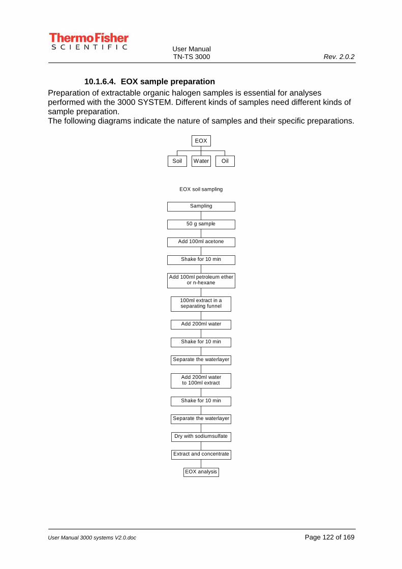
User Manual TN-TS 3000 Rev. 2.0.2
User Manual 3000 systems V2.0.doc Page 122 of 169
10.1.6.4. EOX sample preparation Preparation of extractable organic halogen samples is essential for analyses performed with the 3000 SYSTEM. Different kinds of samples need different kinds of sample preparation. The following diagrams indicate the nature of samples and their specific preparations.
Soil Water Oil
EOX
EOX soil sampling
50 g sample
EOX analysis
Extract and concentrate
Dry with sodiumsulfate
Separate the waterlayer
Shake for 10 min
Add 200ml waterto 100ml extract
Separate the waterlayer
Shake for 10 min
Add 200ml water
100ml extract in aseparating funnel
Add 100ml petroleum etheror n-hexane
Shake for 10 min
Add 100ml acetone
Sampling

User Manual TN-TS 3000 Rev. 2.0.2
User Manual 3000 systems V2.0.doc Page 123 of 169
EOX water sampling (Acc. NEN 6402)
Removal of active chlorine
Separation of organic phaseWater layer pH = 9
Extract with 100 ml petroleum etherSeparation of organic phase
Collect extracts
EOX analysis
Concentrate to 1 ml
Add 100ul hexadecane
Concentrate to 5 ml by evaporation
Dry extracts with sodium sulphate
Extract with 100 mlpetroleum ether
pH = 2
Pour 1 litre o the sampleinto a separating funnel
Store at 4 degr. C
Sampling
EOX oil sampling (Acc. NEN 6600)
Weigh out 2.5 g into a25ml measuring flask
EOX analysis
Filter the extract with a 0.25 um filter
Fill measuring flask with n-hexaan
Sampling

User Manual TN-TS 3000 Rev. 2.0.2
User Manual 3000 systems V2.0.doc Page 124 of 169
10.1.7. Adjusting gas flows Before operation gases have to be supplied with a maximum pressure of 3 bar. Open the gas headers on the gas supply line in the following order. Close all flow meters by turning the black knob in the clockwise direction. (do not over- tighten them) 1. Open the gas headers on the gas supply line. 2. Set the oxygen bypass flow meter to 10 mm (35 mL/min) by turning the black
knob counter clockwise. (left flow meter) The introduction module has to be installed before the next two steps can be executed. 3. Set the oxygen flow meter to 50 mm (330 mL/min), minimum 40 mm (200
mL/min) (middle flow meter) 4. Set the argon flow meter to 40 mm (200 mL/min), minimum 25 mm (90 mL/min)
(right flow meter) (Only operating together with the liquids and solids module.) Note: Instead of manual flow (Rota) meters, digital mass flow controllers can be installed. In this case, all flow settings will be automatically done by the ThEuS software.
10.1.8. Filling the scrubber Before operation the scrubber has to be filled with sulfuric acid.
10.1.8.1. Sulfuric acid scrubber
Special Attention Make sure that the drip tray is clean and dry and has been placed in the scrubber compartment. Place the small beaker under the scrubber.
Fill the scrubber in the following order: 1. Install the selected “sample introduction module” connect it and open the gas
flow. 2. Open the scrubber compartment and position the drip-tray. 3. Shut both stopcocks of the scrubber, the red handles in horizontal position 4. Remove upper glass stopper from the scrubber 5. Fill the scrubber buffer with 95-98 % sulfuric acid 6. Remove any spilled sulfuric acid. 7. Replace upper glass stopper. 8. Check that the lower stopcock of the scrubber is shut. Fill the absorber of the
scrubber to the red line by opening the upper stopcock (red handle in vertical position) and lift up glass stopper until scrubber is filled.

User Manual TN-TS 3000 Rev. 2.0.2
User Manual 3000 systems V2.0.doc Page 125 of 169
9. If the gas is connected take care that a flow is running through the scrubber immediately after filling.
10. Close upper stopcock (red handle in horizontal position) 11. Close the scrubber compartment.
10.1.8.2. NOx-scrubber Fill the scrubber in the following order: 1. Open the titration cell compartment and place the drip-tray. 2. Disconnect the outlet of the splash trap with the NOx-scrubber 3. Fill the NOx scrubber with 95-98 % sulfuric acid till the mark on the glass. 4. Remove any spilled sulfuric acid. 5. Reconnect the outlet of the splash bulb to the NOx-scrubber, using clamp no. 12. 6. If the gas is connected take care that a flow is running through the scrubber
immediately after filling. 7. Close the compartment.
10.1.9. Powering the system If all steps above are carried out carefully and the instrument is connected to a computer the 3000 SYSTEM can be switched on with the ON/OFF switch on the backside of the instrument. 1. Switch on the computer 2. Switch on the 3000 SYSTEM. Now the instrument needs some time to stabilize. From room temperature up to 1000°C for the furnaces, take approximately 30-45 minutes. A fresh titration cell will take up to 10-15 minutes to generate a proper baseline.
10.1.10. Installing a selected Module Place the module on/in the boat driver, located at the right-hand side of the analyzer. Connect all Argon/Helium and Oxygen inlet tubing, coming from the module (quick connector) onto the connector socket found on 3000 SYSTEM. Connect the module with the clamp to the furnace tube and secure it with the screw.

User Manual TN-TS 3000 Rev. 2.0.2
User Manual 3000 systems V2.0.doc Page 126 of 169
10.1.11. Titration cell (chloride) Make sure the cell (the glass) is clean. Any gray deposit should be removed by filling the cell with ammonia and leaving it for 15 minutes in a ventilated cabinet, then rinse thoroughly with water. Pre-rinse the cell with a small quantity of electrolyte in order to remove any excess water. Fill the cell with electrolyte up to a level between the marks/level lines. (Never use organic solvents to clean the cell.) Fill the electrode with the halide electrolyte solution and add the four electrodes like described in paragraph 8.6.1.1. Fill the cell with the correct electrolyte solution, up to the level mark. Before and during cell replenishing, the gain must be set to zero in order to prevent heavy pollution of the cell and/or damage to the coulometer electronics. Once the cell is filled and the electrodes have been inserted, the cell can be placed onto the stirrer motor. If the cell replenishment was carried out correctly, with the bias for the halide-analysis at -315 mV and for the sulfur-analysis at 135-145 mV, a positive signal should be shown. The current has to have a value between approximately 200 and 600 µA. Depending on the speed of the cell (condition of the electrodes) and gain level, the signal should return within 3 to 5 minutes. If upon return, the signal at first drops to negative and then returns to a positive signal to arrive at a base line between approximately -0.5 to +1 µA, you may have a case of overshoot due to the excess gain. For the halide-cell approximately 5 µL of 0.1 to 0.2 M NaCl has to be injected directly into the cell before decreasing the gain. While doing this, make sure the needle tip is fully immersed in the electrolyte in order to obtain a regular signal. This procedure must be carried out twice. If any overshoot occurs, the gain must be decreased. After carrying out the procedure of above, the recovery must be tested. Halide-analysis: A 2 mM solution of NaCl can be used. Inject 10 µL of the solution. In theory, this should result in a yield of 1.92 mC, but in practice this value could be exceeded with approximately 10% due to the contribution of light that enters the cell when the cover is opened, a statically charge coming from the syringe and operator etc. If the test results are correct, the cell, coulometer and PC have been tested and are working properly. If the subsequent connection of the gases results in insufficient yield or reproducibility, the cell need not be included in any further trouble-shooting procedures.

User Manual TN-TS 3000 Rev. 2.0.2
User Manual 3000 systems V2.0.doc Page 127 of 169
10.1.12. Titration cell (sulfur) Make sure the cell (the glass) is clean. Any deposit should be removed by cleaning it with water and/or a tissue paper. Pre-rinse the cell with a small quantity of the sulfur-electrolyte in order to remove any excess water. Fill the cell with electrolyte up to a level between the marks/level lines. (Never use organic solvents to clean the cell.) Add the four electrodes like described in paragraph 8.6.2.1. Fill the cell with the correct electrolyte solution, up to the level mark. Before and during cell replenishing, the gain must be set to zero in order to prevent heavy pollution (incorrect titration) of the cell and/or damage to the coulometer electronics. Once the cell is filled and the electrodes have been inserted, the cell is placed onto the stirrer motor. Connect the sulfur cell to the output of the splash bulb with the gasses turned on. Turn the gain back on. (level set at 10%) If the cell replenishment was carried out correctly, with the bias for the sulfur-analysis at 135-145 mV, a positive signal should show. If the signal goes negative, put the gain to zero again and inject a sample/standard first. This procedure is carried out, using the “liquids module” and an organic sulfur standard. If the sample introduction is finished the gain may be turned to the previous level again. Check if the cell runs “positive” now. Depending on the speed of the cell (condition of the electrodes) and gain level, the signal should return within 3 to 5 minutes. If upon return, the signal at first drops to negative and then returns to a positive signal to arrive at a base line between approximately -0.5 to +1 µA, you may have a case of overshoot due to the excess gain. After carrying out the above procedure, the recovery must be tested. Reproducibility is important at this stage (within 5 %). The yield must be 80 % or higher. If the test results are correct, the cell, coulometer and PC have been tested and are working properly. If the subsequent connection of the gases results in insufficient yield or reproducibility, the cell need not be included in any further trouble-shooting procedures.

User Manual TN-TS 3000 Rev. 2.0.2
User Manual 3000 systems V2.0.doc Page 128 of 169
10.1.13. Gas leakage test coulometric configuration Procedure 1 For reliable and accurate analysis the 3000 SYSTEM needs to be free of leakage. Therefore a gas leak test has to be performed. The next steps explain the gas leak test: 1. Close the flow regulator for the oxygen-supply and lower the Argon-flow to
approximately 5 mm. 2. Observe the flow in the Sulfuric Acid of the scrubber. There still has to be a low
flow visible. 3. Shut down the stirrer of the Titration Cell and observe if a similar bubble appears.
This demonstrates that even at low flow-rates the gas arrives into the Cell and at the same time proves that all other connected items are gas-tight.
Gas leakage test ok > proceed with analysis. Gas leakage test false > proceed with next steps.
The furnace tube, outlet, modules, joints, etc may become very hot during the operation of the 3000 SYSTEM. Carelessness may result in burns.
Procedure 2 1. If there are no bubbles visible, a gas leakage has to be fixed. Adjust flows to the
“normal” levels. (setting according current method) 2. Disconnect the gas stream between furnace output and the “connection furnace
scrubber”. 3. Manually obstruct the gas stream on the outlet (using a septum) and observe the
flow meters. They should drop approximately 5-10 mm within 10-15 seconds. Removing the septum from the output should clearly release pressure from the tube. This indicates that no gas-flow leakage is present in the connectors, Module, Furnace-tube and other joints. The leakage has to be further down the flow path. (leakage could be found in the septum of the module, any gas connector, glass joints, loose clamps, mineralized furnace tube, etc.)

User Manual TN-TS 3000 Rev. 2.0.2
User Manual 3000 systems V2.0.doc Page 129 of 169
4. Connect the “connection furnace scrubber” and “scrubber” again and obstruct the flow, coming from the scrubber. The flow meters should drop approximately 5-10 mm within 10-15 seconds. Removing the septum from the output should clearly release pressure from the scrubber. This indicates that no gas-flow leakage is present in all connected parts in the flow path. The leakage has to be further down the flow path. (leakage could be found in the gas connector going to the scrubber, the glass joints, due to dirt on the grind surface, the furnace tube, connection furnace scrubber, scrubber-inlet, -outlet etc.
5. Install the splash bulb again including the tubing and repeat the “obstruct” procedure.
6. The final check will be the number 3 step from procedure 1. Following these steps should clearly lead to the “problem” and solution in the flow path.

User Manual TN-TS 3000 Rev. 2.0.2
User Manual 3000 systems V2.0.doc Page 130 of 169
10.2. 3000 SYSTEM Normal operation The software controls the operation of the 3000 SYSTEM. Parameters like temperature, sample introduction speed, data acquisition, cell stability, etc, are stored in so called “Method files”. These files are loaded as default- or customer adjustable methods. Generating or modifying methods is clearly described in the software manual. During normal operation small maintenance has to be carried out regularly. The next paragraphs will describe the following subjects: 1. Visible inspection of glassware 2. Glassware maintenance 3. Introduction module 4. Standard setpoints
10.2.1. Visible inspection of glassware All glassware parts should be checked regularly, once a week, on scratches, disposals and blocking of the gas path. After the inspection a gas leak test should be performed. (refer to 10.1.13 for gas leakage test)
10.2.2. Glassware maintenance
10.2.2.1. Scrubber If the capillary in the scrubber (final gas inlet into the sulfuric acid) appears black, this may cause blockage or serious restriction to the flow. In addition, the "soothing" may cause memory effects to occur. Therefore, a clean scrubber is necessary.
Take the necessary precautions to avoid contact with sulfuric acid. Ware protective gloves, goggles and clothing, according safety procedures on the laboratory. Failure to do so may result in physical injury.
Cleaning procedure: 1. Remove all H2SO4 from the scrubber. 2. Remove the drip tray from the system. 3. Disconnect the connecting plug to the scrubber. 4. Remove the bypass gas connection from the glassware. 5. Remove the scrubber from the system and remove all “stop cocks”. 6. Rinse off as much of the pollution as possible (taking care not to damage the
heater ribbon). 7. Rinse out the scrubber with water. 8. Heat the scrubber in an oven at 500 oC for approx. 30 minutes (leaving the
plastic connection plug to protrude through the oven door!). 9. After re-installation, make sure the heater ribbon reaches the set temperature
again (300°C) and carry out the gas test.

User Manual TN-TS 3000 Rev. 2.0.2
User Manual 3000 systems V2.0.doc Page 131 of 169
10.2.2.2. Furnace tube In the furnace tube also, soot is one of the causes of the memory effect. Mineralization can also cause the same effect (the tube sometimes becomes slightly porous). Soot deposited at the end of the furnace tube is relatively easy to remove. 1. Remove the clamp between the tube and the scrubber. 2. Remove the latch between the tube and the cassette. 3. Set the furnace temperature to 1000 oC and pull back the tube halfway (it will
be clean in 10 minutes). The tube becomes opaque on the inside and sometimes on the outside. This can be recognized as mineralization of the tube. The speed of mineralization depends strongly on the sample matrix and the sample quantity. In some cases Thermo Fisher Scientific can remedy this. Please contact the Thermo Fisher Scientific Service/Support Department for more information.
10.2.2.3. Liquids module During the use of the “liquids module” analysis, the inner tube and the injection port can become polluted. Reversing the connected 02 and Ar/He gas flows will burn off this pollution. If required, this can be monitored on the display (base line going up > pollution, baseline coming down again is clean). A temporary increase of the “liquids module” temperature accelerates this process.
Note: Before commencing analysis, make sure the gasses have been reconnected in the correct order!
10.2.2.4. AOX glassware During AOX analysis, the boat and/or frit often cause a memory effect. By introducing samples into the furnace tube too fast, moisture can flow back into the sample introduction section of the AOX glassware (visible as condensation). If this happens, a second peak can occur when the hot boat returns from the furnace. If this is visible, the glassware must be cleaned in an oven. Please contact the Thermo Fisher Scientific Service Department for more information. The effect may also be caused by mineralization of either the boat or the frit, or both. Replacing them may be the only solution. The service life of the frit and the boat often depend on the number of runs, the nature and components of the sample, and whether or not the equipment is rinsed with demineralized water. Removal of any nitrate traces increases the service life of the quartz.

User Manual TN-TS 3000 Rev. 2.0.2
User Manual 3000 systems V2.0.doc Page 132 of 169
10.2.2.5. POX glassware The POX module has a bypass gas flow in “standby” and a sample gas flow during actual analysis. The gas of the bypass flows directly to the coupling, through the valve and into the tube. The sample gas flow travels to the coupling via the valve leading to the long needle, through the sample bottle, the short needle, the long foam vessel pipe, the short foam vessel pipe, the valve and into the furnace tube. Of course, both gas flows must be identical. Check 1. Set the 02 flow at 10 mm (35 mL/min) and close the bypass. 2. Check gas flow through the scrubber. 3. Insert an empty sample bottle with a septum in good condition (in case of
doubt, use a new one) and insert both needles into the empty sample bottle. 4. Press the analyze button at the control-window and check the gas flow that
should be equal to that of point 2. If both gas flows are not equal, a leaking septum or the tubing not fitting properly into the couplings, blocked needles, etc may cause this. (further info on gas-test, trouble shooting 10.1.13)
10.2.2.6. Solids glassware The instructions for “liquids module” and AOX apply for solids.
10.2.3. Introduction module
10.2.3.1. Solids Module Replace the septum when necessary but at least once every week. If a new sample boat is used or the boat is dirty, clean this by introduction into furnace tube during 4 minutes at 1000 oC. (or when used for more difficult sample matrices at 1100°C)
10.2.3.2. Liquids Module Replace the septum when necessary, but at least once every week.
10.2.3.3. AOX Module If a new boat is used or the boat is dirty, clean this by introduction into the furnace tube during 4 minutes at 1000 oC. (or when used for more difficult sample matrices at 1100°C)
10.2.3.4. POX Module Replace the septum after every analysis and check the tubing regularly.

User Manual TN-TS 3000 Rev. 2.0.2
User Manual 3000 systems V2.0.doc Page 133 of 169
10.2.4. Standard setpoints The software controls most of the setpoints. These parameters are related to a method. These methods describe all parameters necessary for running some applications. The following defined methods are as default available in the software: 1. EOX / EOS Extractable organic halogen or organic Sulfur analysis method for
liquid applications 2. AOX / TOX Adsorbable or Total organic halogen analysis method for liquid
applications 3. POX purgable organic halogen analysis method for liquid applications 4. TX / TS-liquids Total halogen or sulfur analysis method for liquid applications 5. TX / TS-gas Total halogen or sulfur analysis method for gas applications 6. TX / TS solids Total halogen or sulfur analysis method for solid applications Other methods are custom made by Thermo Fisher Scientific or created by customers themselves. The software manual describes how these methods can be created/changed. An example of setpoints is given in “Appendix I : Settings”. For more information see software manual.
10.3. 3000 SYSTEM Standby mode When no analyses are carried out for a short period of time (a few days) it is recommended to put the 3000 SYSTEM in standby mode. Follow the next steps: 1. Disconnect the gas supply to the NOx-scrubber. (remove the clamp between the
splash-bulb and the NOx-scrubber) 2. Drain the sulfuric acid scrubber into the small beaker. 3. Close header gas supply or close flow meters by turning the black knob
clockwise. (observe if all acid has left the scrubber before the header is closed) 4. Set the following temperatures:
Heating Setpoint Furnace 1 700°C Furnace 2 700°C Outlet 25°C
Now the instrument is in standby mode.

User Manual TN-TS 3000 Rev. 2.0.2
User Manual 3000 systems V2.0.doc Page 134 of 169
10.4. 3000 SYSTEM shut down When no analysis are carried out for a longer period of time it is recommended to shut the 3000 SYSTEM down. Follow the next steps: 1. Disconnect gas supply to the NOx-scrubber. (remove the clamp between the
splash-bulb and the NOx-scrubber) 2. Drain the sulfuric acid scrubber into the small beaker and discard the acid. 3. Remove NOx-scrubber acid. 4. Close header gas supply and close flow meters by turning the black knob
clockwise. 5. Set the gain to zero in the software and/or disconnect the cathode first. 6. Disconnect the coulometer cables from the cell. 7. Empty the cell and remove the electrodes. 8. Close the 3000 SYSTEM software. 9. Switch off the 3000 SYSTEM. Now the instrument is turned off.

User Manual TN-TS 3000 Rev. 2.0.2
User Manual 3000 systems V2.0.doc Page 135 of 169
11. Running analysis TX/TS mode (coulometric) This chapter gives a brief description of the actual procedure for analysis. Basically there are two possibilities for running samples: Manually or automatically. Once the unit is switched on and all setting like temperature, flows etc have reached their desired levels, the actual analysis may be started.
11.1. Manual analysis in general An analysis is considered a “manual analysis” when the sample is introduced in a “one at the time” sequence. This means: 1. check if the baseline run at the expected level 2. introduce the sample in the introduction module 3. press the start button in the software 4. next the sample is introduced by “hand” or by integrated “boat driver” (software
controlled) 5. combustion and titration takes place 6. a graphic appears on the screen 7. wait until the graphic returns to baseline and terminate the analysis or wait until
the maximum time has elapsed 8. the calculated result appears on the screen and the sequence may be repeated Some system configuration could come without a “boat driver”. This device is responsible for the actual movement of the sample boat and automatic plunger pushing for syringe injection (controlled by stepper motor and software). In case of not having a “boat driver,” the sample boat and plunger from the syringe are controlled by hand.
11.2. Manual analysis using specific modules/methods
11.2.1.1. Manual introduction POX The POX module is normally positioned on top of the 3000 SYSTEM system. The module connector should be inserted into the ID-connector. Closing the software program (controller window) and starting it again initiates the POX module. The POX temperature should be visible on the screen. Check all system parameters like gas flow (see chapter 10.1.13), temperatures, program settings, method selection, detection cell performance (see chapter 10.1.11) etc.

User Manual TN-TS 3000 Rev. 2.0.2
User Manual 3000 systems V2.0.doc Page 136 of 169
The following steps should take you quickly through the procedure and run an actual sample. 1. Open a new queue list and key-in the necessary parameters (for more details,
refer to the software manual) 2. Open “analysis” in the “controller window” and select the box “methods”. Choose
the appropriate POX analysis method according the application. 3. Open “evaluation” and select the “absolute” calculation method (the calibration
field at this point is not used) 4. Place the sample in the POX module (for sample prep refer to: 10.1.6.2) and
allow the first sample to heat up to approximately 60°C, which usually takes about 8 minutes. In the mean while the second sample is placed to avoid waiting time for the next analysis.
5. Lower the injection head of the POX module and observe if both needles have penetrated the septum sufficiently.
6. Select or add in the queue list the sample to be analyzed and press “analyze”. Depending on program settings the analysis terminates when sample is completely purged and the baseline reaches its normal baseline level again. Manual termination is possible by keying in a lower number of minutes/seconds analysis time or putting the cursor at the finishing baseline and click on the right mouse key. This will automatically key in the selected time.
7. The next sample should have reached operational temperature and is ready for analysis. Select the sample to be analyzed and repeat the steps starting from 5.
11.2.1.2. Manual introduction AOX The AOX module is positioned in the boat driver and connected onto the furnace tube of the 3000 SYSTEM system. The AOX module connector should be inserted into the ID-connector. Closing the software program (controller window) and starting it again initiates the AOX module settings. The AOX temperature settings should be visible on the screen. Check all system parameters like gas flow (see chapter 10.1.13), temperatures, program settings, method selection, detection cell performance (see chapter 10.1.11) etc.
Warning Do not use this introduction module for samples containing significant quantities of (combustible) organic components, like oil, waxes etc.. The sample is introduced in a flow of pure oxygen. Any combustible component will ignite prematurely.
The following steps should take you quickly through the procedure and run an actual sample. 1. Open a new queue list and key-in the necessary parameters (for more details,
refer to the software manual) 2. Open “analysis” in the “controller window” and select the box “methods”. Choose
the appropriate AOX analysis method (batch or column) according the application. (for more details see chapter 10.1.6.1)

User Manual TN-TS 3000 Rev. 2.0.2
User Manual 3000 systems V2.0.doc Page 137 of 169
3. Open “evaluation” and select the “absolute” calculation method (the calibration field at this point is not used)
4. Place the prepared carbon-sample in the AOX module. 5. Select or add in the queue list the sample to be analyzed and press “analyze”.
Depending on program settings the analysis terminates when sample is completely oxidized and the baseline reaches its starting point again. Manual termination is possible by keying in a lower number of minutes/seconds analysis time or putting the cursor at the finishing baseline and click on the right mouse key. This will automatically key in the selected time. Note that a certain “cooling time” is needed for the sample boat to reach an acceptable temperature again. A hot boat could oxidize the sample in an early stage, producing erratic numbers. (typical cooling time is 4 minutes)
6. Now the 3000 SYSTEM is ready for the next analysis. Select the sample to be analyzed and repeat the mentioned steps starting from 4.
11.2.1.3. Manual introduction Solids, water and heavy hydrocarbons The Solids module is positioned in the boat driver and connected onto the furnace tube of the 3000 SYSTEM. The Solids module connector should be inserted into the ID-connector. Closing the software program (controller window) and starting it again initiates the Solids module settings. The Solids temperature settings should be visible on the screen. Check all system parameters like gas flow (see chapter10.1.13), temperatures, program settings, method selection, detection cell performance (see chapter10.1.11) etc. The following steps should take you quickly through the procedure and run an actual sample. 1. Open a new queue list and key-in the necessary parameters (for more details,
refer to the software manual) 2. Open “analysis” in the “controller window” and select the box “methods”. Choose
the appropriate “Solids analysis method” according the application. (for more details check your application note or check the web: www.thermo.com )
3. Open “evaluation” and select the “absolute” calculation method (the calibration field at this point is not used)
4. Place the sample in the Solids module. (by weight in a sample cup or via syringe by volume injection in a sample cup)
5. Select or add in the queue list the sample to be analyzed and press “analyze”. Depending on program settings the analysis terminates when sample is completely oxidized and the baseline reaches its starting point again. Manual termination is possible by keying in a lower number of minutes/seconds analysis time or putting the cursor at the finishing baseline and click on the right mouse key. This will automatically key in the selected time. Note that a certain “cooling time” is needed for the sample boat to reach an acceptable temperature again. A hot boat could oxidize the sample in an early stage, producing erratic numbers. (typical cooling time is 4 minutes)
6. Now the 3000 SYSTEM is ready for the next analysis. Select the sample to be analyzed and repeat the mentioned steps starting from 5.

User Manual TN-TS 3000 Rev. 2.0.2
User Manual 3000 systems V2.0.doc Page 138 of 169
11.2.1.4. Manual injection EOX and “light hydrocarbons” The EOX module is positioned in the boat driver and connected onto the furnace tube of the 3000 SYSTEM. The EOX module connector should be inserted into the ID-connector. Closing the software program (controller window) and starting it again initiates the EOX module settings. The EOX temperature settings should be visible on the screen. Check all system parameters like gas flow (see chapter10.1.13), temperatures, program settings, method selection, detection cell performance (see chapter10.1.11) etc. The following steps should take you quickly through the procedure and run an actual sample. 1. Open a new queue list and key-in the necessary parameters (for more details,
refer to the software manual) 2. Open “analysis” in the “controller window” and select the box “methods”. Choose
the appropriate EOX/TX analysis method according the application. (for more details see chapter10.1.6.4)
3. Open “evaluation” and select the “absolute” calculation method (the calibration field at this point is not used)
4. Take a 100µL syringe and fill it with the prepared EOX or TX (light hydrocarbon) sample.
5. Select or add in the queue list the sample to be analyzed and press “analyze”. 6. Insert the needle through the septum and let the syringe rest on the support. The
plunger pusher in the “boat driver” performs the injection itself. Injection speed and volume are software controlled and application dependable.
7. The analysis terminates when sample is completely oxidized and the baseline reaches its starting point again. Manual termination is possible by keying in a lower number of minutes/seconds analysis time or putting the cursor at the finishing baseline and click on the right mouse key. This will automatically key in the selected time. Now the 3000 SYSTEM is ready for the next analysis. Select the sample to be analyzed and repeat the mentioned steps starting from 4.
11.3. Automatic analysis in general An analysis is considered “automatic analysis” once samples are unattended introduced into a “sample introduction module” by means of an “autosampler” and the sequence runs all samples according the queue list. In order to prepare the 3000 SYSTEM plus autosampler for actual analysis, a few parameters should be checked. 1. check if the baseline runs at the expected level 2. place the samples in the autosampler and built a queue list. 3. press the “analyze” button. 4. next the sample is introduced by the autosampler and/or “boat driver” (software
controlled) 5. combustion and titration takes place 6. a titration curve appears on the screen

User Manual TN-TS 3000 Rev. 2.0.2
User Manual 3000 systems V2.0.doc Page 139 of 169
7. the unit waits until the curve has returned to baseline and terminates the analysis as soon as the maximum time has elapsed or the appropriate baseline level is reached. (depending on software settings)
8. the calculated result appears on the screen and the sampler starts the next sample injection/introduction.
11.4. Automatic analysis using specific modules/methods
11.4.1.1. Automatic analysis AOX The automatic sample handling and introduction for AOX batch method, using the ESA2000 and AOX/TOX column method, using the ECA1700 are found in chapters: • 7.2 ECA1700 column sampler • 7.3 ESA2000 AOX batch method
11.4.2. Automatic introduction Solids, water and “heavy” hydrocarbons The automatic sample handling and introduction for solids samples or water, waste water for TX/TS analysis is carried out by the ESA2000 auto sampler. The sampler is also used for heavy hydrocarbons like waste oil, crude or anything with a high boiling point or viscosity. The sample is introduced using a sample cup. Simply determine the weight, key it in the software and place it into ESA2000, which in combination with the solids module, carries it into the furnace. Detailed information concerning the ESA2000 is found in chapter: • 7.3 ESA2000 solids auto sampler
11.4.2.1. Automatic injection EOX and “light hydrocarbons” Automatic sample introduction for EOX or light hydrocarbons is carried out by the NeXYZ auto sampler. The sampler is capable to pick up sample volume from a vial positioned in a sample tray and control the speed of injection into the liquids EOX module. Detailed information is found in the User’s Guide of the NeXYZ.

User Manual TN-TS 3000 Rev. 2.0.2
User Manual 3000 systems V2.0.doc Page 140 of 169
12. Troubleshooting Nitrogen-Sulfur UV mode
The 3000 system has been designed to achieve a high level of reliability. In case of problems or failure, these troubleshooting guidelines will be helpful.
Malfunction Possible cause Action The response is too slow or Perma pure is blocked Replace the perma pure Recovery is too low or too high Perma pure is melted Replace the perma pure Soothing in the perma pure Clean it or replace it by a new
perma pure Vacuum pump is out of order
(drying of the gasses) Contact the Thermo Fisher Scientific Service Department
Gas leakage Check the apparatus Wrong calibration line Analyze a new calibration set
or choose the right one Using a wrong size needle Replace the needle Wrong type of filter installed Replace for proper one Filter is soothed Replace or clean the Filter Recovery is too low Furnace temperature is incorrect Check the oven temperature
High blank values for the solvent used for the Liquid analysis
Check the solvent, if necessary clean by distillation.
Dirty glass fiber filter Replace or clean filter The injected volume has been increased by the contents of the needle (manual injection)
Correct for needle content
Recovery is too high
Heating to a higher temperature has not adequately cleaned sample boat.
Clean the sample boat by heating, e.g. by increasing the furnace temperature.
Software Error Contact the Thermo Fisher Scientific Service Department
Irregular or repeating spikes
Incorrect communication with IOC-card
Contact the Thermo Fisher Scientific Service Department
Incorrect baseline If the baseline does not behave as outlined above, this may be caused by a number of factors
Contact the Thermo Fisher Scientific Service Department
Too much noise Pollution Clean new/used glassware Check the tubing Check the temperature Check the environmental air for high concentrations S
Incorrect communication with IOC-card
Contact the Thermo Fisher Scientific Service Department

User Manual TN-TS 3000 Rev. 2.0.2
User Manual 3000 systems V2.0.doc Page 141 of 169
Malfunction Possible cause Action Generally too high baseline Incorrect communication with
IOC-card Contact the Thermo Fisher Scientific Service Department
Gas problems Check gas supply and the sample introduction section When possible connect the gas bottles separately, so it is possible to circumvent the gas supply network
No gas routing into the UV or Nitrogen detector
Check gas path
Disconnected data cable Check cable back and forth
no signal
Defective TS/TN board Check if there is any signal from the ref. cable (must be 0-10 V) and contact the Thermo Fisher Scientific Service Department

User Manual TN-TS 3000 Rev. 2.0.2
User Manual 3000 systems V2.0.doc Page 142 of 169
13. Troubleshooting Coulometric option
Malfunction Possible cause Action No cell current. Gain control on zero. Turn the gain control to 7-15. Cathode or anode disconnected. Re-connect the cathode or
anode. Coulometer cable disconnected
from PC or cell. Check the wiring and reconnect.
Cell current deviates greatly from zero or fluctuates.
Electrical connection between cell and microcoulometer is broken.
Fill the titration cell with electrolyte solution and check whether electrolyte solution is present in the side arm of the titration cell.
Bad or badly connected reference electrode.
Change reference electrode for a spare one. Check cables.
Cell current is large and positive. Cl- is leaking from the reference electrode into the cell.
Change the reference electrode.
Cell current is large and negative.
The system is severely contaminated with silver ions.
Change the electrolyte solution.
Cell current is unstable. Irregular stirring, stirrer element out of phase; the cell is not firmly located on the stirrer motor.
Check the stirrer element and stirrer motor.
The silver surface of the indicator electrode has not yet stabilized e.g. after polishing or renewal.
Allow the electrode to stabilize for a period of time or replace with a stabilized electrode.
Dirty cell. After removing the electrodes, flush the cell thoroughly with ammonia, demineralized water and electrolyte solution.
Droplets of condensation falling back into the cell.
Dry the electrode holder and the electrodes.
Changing exposure to light of the cell.
Make sure that the cell cabinet is properly shut.
Temperature fluctuations in the cell.
Prevent excessive heating or cooling of the cell cabinet. Draughts, sunlight, etc may cause heating or cooling.
Small volume of titration solution Top up the titration solution

User Manual TN-TS 3000 Rev. 2.0.2
User Manual 3000 systems V2.0.doc Page 143 of 169
Malfunction Possible cause Action
Incorrect bias potential, making the system insensitive to chloride and silver ions.
Check the potential difference between the indicator electrode pair. The bias setting should be –315 mV.
No chloride titrated into the solution.
Use a syringe and long needle to add chloride.
Loose anode or Cathode Reconnect Disconnected wiring Reconnect
No response to Chloride dosage.
Broken wiring/Electrodes Call service department The cell is severely Contaminated with AgCI.
After removing the electrodes, clean the cell with concentrate ammonia, large amounts of demineralized water and electrolyte solution.
The composition of the electrolyte is incorrect.
Replace the solution with new solution with the correct solution.
Incorrect bias potential, causing a delay in the response of the indicator electrode.
Adjust the bias potential until it is correct.
Titration time is too long
Indicator electrode is slow. Replace the indicator electrode for example by switching it with the anode.
Titration time is too slow Large volume of titration solution Increase the gain or drain off some titration solution.
Titration time is too fast Gain level is set too high Reduce the gain Small volume of titration solution Top up the titration solution
Sulfuric acid solution is severely contaminated
Purge the sulfuric acid solution for 15 minutes or replace it with clean solution.
Contaminated gases (oxygen, argon)
Clean the gases, for example by inserting a gas cleaning filter between the gas cylinders and the ECS1200.
High baseline due to high current Cell current is unstable.
Apparatus is contaminated with organic halogen compounds
Clean the titration cell with conc. ammonia, water and demin. water.

User Manual TN-TS 3000 Rev. 2.0.2
User Manual 3000 systems V2.0.doc Page 144 of 169
Malfunction Possible cause Action
Gain is set too low. Increase gain level. Long titration time. Gas flows too low Check the flow setting and the
apparatus for blockages in the scrubber or titration cell inlet. Check the apparatus for leaks (including the septum of the EOX and POX modules).
Recovery too low Furnace temperature is incorrect Check the oven temperature Inlet temperature in the liquids
module is incorrect Check the inlet temperature
Organic halogen condensation in the injection needle
Add hexadecane to the extract and raise the injection speed to a maximum of 0.5 μI per second.
Gas leaks Check the apparatus for the presence of 'Teflon' sleeves, etc.
Too little electrolyte in the titration cell so that not all Halogen is absorbed.
Top up the titration solution
High blank values for the solvent used for the Liquid analysis
Check the solvent, if necessary clean by distillation.
The injected volume has been increased by the contents of the needle
Correct for needle content
Adsorbed halogen is being released during combustion as a result of pronounced expansion (AOX)
Repeat the measurement several time or clean the glasswork by heating.
Recovery is too high
Heating to a higher temperature has not adequately cleaned sample boat.
Clean the sample boat by heating, e.g. by increasing the furnace temperature.

User Manual TN-TS 3000 Rev. 2.0.2
User Manual 3000 systems V2.0.doc Page 145 of 169
Malfunction Possible cause Action
Air bubbles in the injection syringe (EOX, EOS)
Clean the syringe and check if there still is enough wash solution available
Condense in the splash bulb (HCl absorption)
Dry the splash bulb and check the O2 and Ar/He flows
Irregular or repeating spikes
A defect in the scrubber heating or low temperature setting, (HCI absorption) due to condenses in the heater section
Increase the temperature to normal levels. Contact the Thermo Fisher Scientific Service Department
Furnace temperature or gas flow is too low (soothing); injection speed is too high (EOX soothing).
Check the possible causes
In correct baseline If the baseline does not behave as outlined above, this may be caused by a number of errors
Contact the Thermo Fisher Scientific Service Department
Too much noise Pollution Clean new/used glassware Refill the coulometer cell Check the tubing Check the temperature program
Cell problems
Check whether the baseline drops to an acceptable level when the cell is disconnected from the scrubber
Generally too high baseline
Gas problems Check gas supply and the sample introduction section When possible connect the gas bottles separately, so it is possible to circumvent the gas supply network

User Manual TN-TS 3000 Rev. 2.0.2
User Manual 3000 systems V2.0.doc Page 146 of 169
14. Consumables and spare parts The list below gives an overview of consumables and spare parts needed for the 3000 system, samplers and additional system features. This list is updated September 2004.
SPARE PARTS TS 3000 PGENE0031 Permapure scrubber complete PGENE0032 Permapure dryer PANAL0126 Turbo tube model 3000 MODUL0004 Quartz combustion boat Solids PGENE0002 Syringe 100 µL, 71 mm needle, p.s. 5 PGENE0004 Injection needle Hamilton, 71mm, p.s. 5, 3 pcs TS3000003 UV scrubber CONSUMABLES TS 3000 PGENE0052 Glass fiber filters, 10 pcs PANAL0025 Septum, diam. 12mm, 10 pieces PINJE0012 Quartz sample boat, solids PANAL0211* Set of Standards; 0, 1, 5, 10 mg S/L di-n-butyl sulfide in
toluene dibenzothiophene, 1 mg S/L PANAL0125 Combustion tube universal model 3000 PANAL0174 Ceramic needle, 150 mm SPARE PARTS TN 3000 PGENE0031 Permapure scrubber complete PGENE0032 Permapure dryer TN3000022 Ozone killer CONSUMABLES TN 3000 PANAL0161 Paper filters 5µm, 10 pcs PGENE0029 Catalyst Pt on ceramic base, 100 gr PANAL0025 Septum, diam. 12mm, 10 pieces PANAL0167* Ammoniumsulphate, 50 gr PANAL0168* Potassiumnitrate, 50 gr SPARE PARTS ORGANIC APPLICATION PANAL0126 Turbo tube model 3000 MODUL0004 Quartz combustion boat Solids PGENE0039 Syringe 100 µl, 120 mm needle, p.s. 1 PGENE0038 Injection needle, 120 mm, p.s. 1, 3 pcs

User Manual TN-TS 3000 Rev. 2.0.2
User Manual 3000 systems V2.0.doc Page 147 of 169
CONSUMABLES ORGANIC APPLICATION PINJE0012 Quartz sample boat, solids PANAL0025 Septum, diam. 12mm, 10 pieces PANAL0221* Benzonitril in toluene standards:
1, 10, 50 mg N/L PANAL0220* Benzonitril in iso-octane standards:
100, 200, 500, 1000, 2000, 5000 mg N/L SPARE PARTS ECS 3000 PANAL0021 Gasinlet ECS300006 Scrubber ECS 3000 ECS200006 Splash bulb ECS 2000/3000 ECS300009 Connection tube furnace/scrubber 3000 ECS300010 Connector to gasinlet ECS 3000 SPARE PARTS CHLORINE PANAL0046 Halogens titration cell, capillary PANAL0047 Electrode container capillary cell PANAL0049 Generating electrode, Ag, cap. cell PANAL0050 Measuring electrode, Ag, cap. Cell PANAL0051 Cathode, Pt, Cap. Cell PANAL0052 Halogen reference electrode, 3M KCl saturated with AgCl SPARE PARTS SULPHUR PANAL0072 Sulphur cell iodometric, 35mL PANAL0073 Electrode container, 35mL cell PANAL0074 Generating electrode, Pt, 35mL cell PANAL0075 Measuring electrode, Pt, 35mL cell PANAL0076 Sulphur reference electrode, Pt PANAL0092 Cathode, Pt PANAL0038 Halogens scrubber CONSUMABLES TX/TS LIQUIDS PANAL0025 Septum, diam. 12mm, 10 pieces PANAL0095* Standard Aldrin in water, 0 and 5 mg CI/L 10 x 2 mL PANAL0211* Set of Standards: Di-n-Butyl Sulfide in toluene:
1, 5, 10 mg S/L PGENE0002 Syringe 100 µL, 71 mm needle, p.s. 5 PGENE0004 Injection needle Hamilton, 71mm, p.s. 5, 3 pcs CONSUMABLES TX/TS SOLIDS PINJE0012 Quartz sample boat, solids

User Manual TN-TS 3000 Rev. 2.0.2
User Manual 3000 systems V2.0.doc Page 148 of 169
CONSUMABLES AOX BATCH PANAL0094* Standard p-chlorophenol, 200 mg CI/L, 20 mL PPTRE0047 Quartzfrit, 3 pieces PPTRE0049 Activated carbon AOX batch 50 gr PPTRE0058 Activated carbon AOX batch, 10 gr CONSUMABLES AOX COLUMN PANAL0094* Standard p-chlorophenol, 200 mg CI/L, 20 mL PGLAS0032 Quartz samplecup AOX columnmethod PPTRE0012 Activated carbon AOX column, 50 gr PPTRE0022 Ejectiontool CONSUMABLES EOX PANAL0025 Septum, diam. 12mm, 10 pieces PANAL0095* Standard Aldrin in water, 0 and 5 mg CI/L 10 x 2 mL PANAL0097* Blank to standard aldrin, 5 x 2 mL PGENE0002 Syringe 100 µL, 71 mm needle, p.s. 5 PGENE0004 Injection needle Hamilton, 71mm, p.s. 5, 3 pcs CONSUMABLES POX PINJE0003 POX samplebottle 100 mL complete PINJE0002 Septum, 24mm, 10 pieces PANAL0102* Standard DiChloroMethane 10 mg Cl/L; 10 mL SPARE PARTS ELS 3000 ELS200003 Vial caps, 100 pieces ELS200016 ELS furnace needle, 1 piece ELS200042 Vials 2 mL, 100 pcs ELS300005 Sampler needle ELS 3000 ELS300006 Septa 7.7 mm PTFE, 100 pcs ELS300003 Washbottle ELS 3000 ELS300004 Screwcap washbottle ELS 3000 ELS300007 Vial 40 mL for washsolution ELS200015 PEEK fitting kit ELS200032 ELS furnace needle coupler
Thermo Fisher Scientific does not supply chemical for the combustion analyzers. Please consult you local Thermo Fisher Scientific distributor for information.

User Manual TN-TS 3000 Rev. 2.0.2
User Manual 3000 systems V2.0.doc Page 149 of 169
SPARE PARTS EGM 1700/II EGM170007 Expansion vessel coated EGM170016 Capillary for EGM 1700 EGM170008 Metal sample loop, 100 µL EGM170014 Metal sample loop, 10 mL
SPARE PARTS ESA 2000 AOX MODUL0011 Boatguiding tube AOX for ESA/ECS3000 PGLAS0602 Quartz combustion boat AOX for ESA/ECS3000 PPTRE0047 Quartzfrit, 3 pieces
SPARE PARTS TN WATER TN3000-065 Glass parts Cold trap TN3000-068 Furnace tube complete TN3000-063 Furnace tube with ceramic inlay TN3000-066 Gas outlet tube TN3000-064 Scraper tool TN3000-075 None return tube PMECH-0007 Clamp KS-18 TN3000-061 Boat TN3000-067 Nickel sample cylinder TN3000-062 Introduction module complete ELS2100-12 Funnel for needle PANAL 0025 Septum 12mm (10 pieces) MODUL 0006 Stopper for septum ELS215011 Needle 1/16” 230 mm long (3 pieces) PMECH-0008 PTFE sleeve NS29.2 PMECH-0009 Clamp (fork) NS29.2 MODUL-0009 Boat guiding tube (‘AOX’)
SPARE PARTS ESA 2000 (For Solids applications)
ESA200029 Sample cups solids ESA 2000 ESA200030 Inlay for ESA200029
The use of parts, which are not manufactured/approved by Thermo Fisher Scientific, could result into exclusion of warranty arrangements.

User Manual TN-TS 3000 Rev. 2.0.2
User Manual 3000 systems V2.0.doc Page 150 of 169
15. Appendix I : Settings
Met
hod
C
oolfo
rce
Coo
lNO
rm F
urn.
1
F
urn.
2
In
let
Out
let
Arg
on/H
el
O
xyge
n
Ext
. Oxy
gen
Ozo
nato
r Byp
ass
Nee
dle
F
ast.
F
ast
In
ject
ion
Inj
ectio
n
Mea
sure
.
N
Orm
/std
N
Orm
/std
N
Orm
/std
N
Orm
/std
tu
rbo
Pos
ition
Spe
ed
Pos
ition
S
peed
so
rt
%
%
c
elsi
us
c
elsi
us
ce
lsiu
s
cel
sius
m
m
m
m
m
m
m
m
mm
mm
m
m
m
m/s
ec
m
m
m
m/s
ec
s
ec.
Liq-
Pet
ro
10
10
850
/700
10
00/7
00
----
----
-
60/
10
65
40
20
40/
50
10
/15
120
65.
0
1
5
110
0
.6
1
90
Liq-
Wat
er
10
10
900
/700
9
00/7
00
----
----
-
60
/10
5
0/65
4
0
2
0
40
/50
05
120
55
.0
15
110
1
.2
2
40
Met
hod
C
oolfo
rce
Coo
lNO
rm F
urn.
1
F
urn.
2
In
let
Out
let
Arg
on/H
el
O
xyge
n
Ext
. Oxy
gen
Byp
ass
Nee
dle
inj
. Spe
ed
.
NO
rm/s
td
NO
rm/s
td
NO
rm/s
td
NO
rm/s
td
tu
rbo
N
Orm
/turb
o
so
rt
%
%
c
elsi
us
c
elsi
us
ce
lsiu
s
cel
sius
m
m
m
m
m
m
m
m
m
m
m
m/s
ec
Sol
-Pet
ro
10
0
100
850/
700
1
000/
700
--
----
---
6
0/10
50
30
20
30
----
----
--
----
----
-
S
ol-W
ater
1
00
10
0
900
/700
9
00/7
00
--
----
---
6
0/10
50
30
20
30
----
----
--
----
----
-
Ti
ps:
1)
The
tem
pera
ture
for t
he s
olid
s m
etho
d ca
n be
hig
her,
but t
hat d
epen
ds o
f the
sor
t of s
ampl
e yo
u w
ant t
o m
easu
re.
2)
Whe
n yo
u us
e a
75 m
m n
eedl
e (1
00 μ
l) th
e ne
xt v
alue
can
be
used
for t
he in
ject
ion
spee
d 0.
1 m
m/s
ec =
0.1
67 μ
l/sec

User Manual TN-TS 3000 Rev. 2.0.2
User Manual 3000 systems V2.0.doc Page 151 of 169
16. Appendix II International Chemical Safety Cards TOLUENE ICSC: 0078
TOLUENE Methylbenzene Toluol C6H5CH3/C7H8 Molecular mass: 92.1
CAS # 108-88-3 RTECS # XS5250000 ICSC # 0078 UN # 1294 EC # 601-021-00-3
TYPES OF HAZARD/ EXPOSURE
ACUTE HAZARDS/ SYMPTOMS PREVENTION FIRST AID/
FIRE FIGHTING
FIRE Highly flammable.
no open flames, no sparks, and no smoking.
Powder, AFFF, foam, carbon dioxide.
EXPLOSION
Vapour/air mixtures are explosive.
Closed system, ventilation, explosion-proof electrical equipment and lighting. Prevent build-up of electrostatic charges (e.g., by grounding). Do NOT use compressed air for filling, discharging, or handling.
In case of fire: keep drums, etc., cool by spraying with water.
EXPOSURE
STRICT HYGIENE! AVOID EXPOSURE OF (PREGNANT) WOMEN!
INHALATION Dizziness. Drowsiness. Headache. Nausea. Unconsciousness.
Ventilation, local exhaust, or breathing protection.
Fresh air, rest. Artificial respiration if indicated. Refer for medical attention.
SKIN Dry skin. Redness.
Protective gloves.
Remove contaminated clothes. Rinse and then wash skin with water and soap. Refer for medical attention.
EYES
Redness. Pain.
Safety goggles or face shield.
First rinse with plenty of water for several minutes (remove contact lenses if easily possible), then take to a doctor.
INGESTION
Abdominal pain. Burning sensation (further see Inhalation).
Do not eat, drink, or smoke during work.
Rinse mouth. Give a slurry of activated charcoal in water to drink. Do NOT induce vomiting. Refer for medical attention.
SPILLAGE DISPOSAL STORAGE PACKAGING & LABELLING Collect leaking liquid in sealable containers. Absorb remaining liquid in sand or inert absorbent and remove to safe place. Do NOT wash away into sewer (extra personal protection: self-contained breathing apparatus).
Fireproof. Separated from strong oxidants.
F symbol Xn symbol R: 11-20 S: (2-)16-25-29-33 UN Hazard Class: 3 UN Packing Group: II
SEE IMPORTANT INFORMATION ON BACK ICSC: 0078 Prepared in the context of co-operation between the International Program on Chemical Safety &
the Commission of the European Communities © IPCS CEC 1993

User Manual TN-TS 3000 Rev. 2.0.2
User Manual 3000 systems V2.0.doc Page 152 of 169
International Chemical Safety Cards TOLUENE ICSC: 0078
I M P O R T A N T D A T A
PHYSICAL STATE; APPEARANCE:COLOURLESS LIQUID , WITH CHARACTERISTIC ODOUR. PHYSICAL DANGERS: The vapour is heavier than air and may travel along the ground; distant ignition possible. As a result of flow, agitation, etc., electrostatic charges aregenerated. CHEMICAL DANGERS: Reacts violently with strong oxidants causing fire and explosion hazard. OCCUPATIONAL EXPOSURE LIMITS (OELs): TLV: 50 ppm; 188 mg/m3 (as TWA) (skin) (ACGIH 1993-1994).
ROUTES OF EXPOSURE: The substance can be absorbed into the body by inhalation, through the skin and by ingestion. INHALATION RISK: A harmful contamination of the air can be reached rather quickly on evaporation of this substance at 20°C. EFFECTS OF SHORT-TERM EXPOSURE: The substance irritates the eyes and the respiratory tract. Exposure could cause central nervous system depression. Exposure at high levels may result in cardiac dysrhythmia, unconsciousness and death. EFFECTS OF LONG-TERM OR REPEATED EXPOSURE: Repeated or prolonged contact with skin may cause dermatitis. The substance may have effects on the central nervous system , resulting in decreased learning ability and psychological disorders. Animal tests show that this substance possibly causes toxic effects upon human reproduction.
PHYSICAL PROPERTIES
Boiling point: 111°C Melting point: -95°C Relative density (water = 1): 0.87 Solubility in water: SO2ne Vapour pressure, kPa at 20°C: 2.9 Relative vapour density (air = 1): 3.2
Relative density of the vapour/air-mixture at 20°C (air = 1): 1.06 Flash point: 4°C c.c.°C Auto-ignition temperature: 480°C Explosive limits, vol% in air: 1.1-7.1 OctaSO2l/water partition coefficient as log Pow: 2.69
ENVIRONMENTAL DATA
N O T E S Depending on the degree of exposure, periodic medical examination is indicated. Transport Emergency Card: TEC (R)-31 NFPA Code: H 2; F 3; R 0;
IMPORTANT LEGAL NOTICE:
Neither the CEC or the IPCS nor any person acting on behalf of the CEC or the IPCS is responsible for the use which might be made of this information. This card contains the collective views of the IPCS Peer Review Committee and may not reflect in all cases all the detailed requirements included in national legislation on the subject. The user should verify compliance of the cards with the relevant legislation in the country of use.

User Manual TN-TS 3000 Rev. 2.0.2
User Manual 3000 systems V2.0.doc Page 153 of 169
International Chemical Safety Cards ARGON ICSC: 0154
ARGON
(liquefied, cooled) Ar
Atomic mass: 39.95 CAS # 7440-37-1 RTECS # CF2300000 ICSC # 0154 UN # 1951 TYPES OF HAZARD/ EXPOSURE
ACUTE HAZARDS/ SYMPTOMS PREVENTION FIRST AID/
FIRE FIGHTING
FIRE
not combustible. Heating will cause rise in pressure with risk of bursting.
For cylinders, see notes. In case of fire in the surroundings: all extinguishing agents allowed.
EXPLOSION
EXPOSURE
INHALATION Asphyxia. Dizziness. Unconsciousness.
Ventilation.
Fresh air, rest. Artificial respiration if indicated. Refer for medical attention.
SKIN
ON CONTACT WITH LIQUID: FROSTBITE.
Cold-insulating gloves. Protective clothing.
ON FROSTBITE: rinse with plenty of water, do NOT remove clothes. Refer for medical attention.
EYES
Pain. Blurred vision. Severe deep burns.
Safety goggles, or face shield.
First rinse with plenty of water for several minutes (remove contact lenses if easily possible), then take to a doctor.
INGESTION
SPILLAGE DISPOSAL STORAGE PACKAGING & LABELLING Ventilation. NEVER direct water jet on liquid (extra personal protection: self-contained breathing apparatus).
Store outside or in a separate well-ventilated building. Cool.
UN Hazard Class: 2.2
SEE IMPORTANT INFORMATION ON BACK
ICSC: 0154 Prepared in the context of co-operation between the International Programme on Chemical Safety & the Commission of the European Communities © IPCS CEC 1993

User Manual TN-TS 3000 Rev. 2.0.2
User Manual 3000 systems V2.0.doc Page 154 of 169
International Chemical Safety Cards ARGON ICSC: 0154 I M P O R T A N T D A T A
PHYSICAL STATE; APPEARANCE:COLOURLESS, ODOURLESS, LIQUEFIED GAS. PHYSICAL DANGERS: The gas is heavier than air and may accumulate in low ceiling spaces causing deficiency of oxygen. CHEMICAL DANGERS: OCCUPATIONAL EXPOSURE LIMITS (OELs): TLV not established.
ROUTES OF EXPOSURE: The substance is absorbed into the body by inhalation. INHALATION RISK: On loss of containment this gas can cause suffocation by lowering the oxygen content of the air in confined areas. EFFECTS OF SHORT-TERM EXPOSURE: The liquid may cause frostbite. EFFECTS OF LONG-TERM OR REPEATED EXPOSURE:
PHYSICAL PROPERTIES
Boiling point: -185.9°C Melting point: -189.2°C
Solubility in water, mL/100 mL at 20°C: 3.4 Relative vapour density (air = 1): 1.66
ENVIRONMENTAL DATA
N O T E S UN number 1006 for argon, compressed. In case of fire: keep cylinder cool by spraying with water. High concentrations in the air cause a deficiency of oxygen with the risk of unconsciousness or death.
Transport Emergency Card:TEC (R)-17
IMPORTANT LEGAL NOTICE:
Neither the CEC or the IPCS nor any person acting on behalf of the CEC or the IPCS is responsible for the use which might be made of this information. This card contains the collective views of the IPCS Peer Review Committee and may not reflect in all cases all the detailed requirements included in national legislation on the subject. The user should verify compliance of the cards with the relevant legislation in the country of use.

User Manual TN-TS 3000 Rev. 2.0.2
User Manual 3000 systems V2.0.doc Page 155 of 169
International Chemical Safety Cards OXYGEN ICSC: 0138
OXYGEN Oxygen, compressed
(cylinder) O2
Molecular mass: 32.0 CAS # 7782-44-7 RTECS # RS2060000 ICSC # 0138 UN # 1072 EC # 008-001-00-8 TYPES OF HAZARD/ EXPOSURE
ACUTE HAZARDS/ SYMPTOMS PREVENTION FIRST AID/
FIRE FIGHTING
FIRE
not combustible but enhances combustion of other substances. Many reactions may cause fire or explosion. Heating will cause rise in pressure with risk of bursting.
no open flames, no sparks, and no smoking. No contact with flammable substances. no contact with fuels and other combustible materials.
In case of fire in the surroundings: all extinguishing agents allowed.
EXPLOSION
Risk of fire and explosion on contact with combustible materials such as oils or fats.
In case of fire: keep cylinder cool by spraying with water. Combat fire from a sheltered position.
EXPOSURE
INHALATION
SKIN
EYES
Redness.
Safety goggles.
First rinse with plenty of water for several minutes (remove contact lenses if easily possible), then take to a doctor.
INGESTION
SPILLAGE DISPOSAL STORAGE PACKAGING & LABELLING Evacuate danger area! Consult an expert! Ventilation.
Fireproof. Separated from combustible and reducing substances. Cool.
O symbol R: 8-34 S: 21 UN Hazard Class: 2.2
SEE IMPORTANT INFORMATION ON BACK
ICSC: 0138 Prepared in the context of co-operation between the International Programme on Chemical Safety & the Commission of the European Communities © IPCS CEC 1993

User Manual TN-TS 3000 Rev. 2.0.2
User Manual 3000 systems V2.0.doc Page 156 of 169
International Chemical Safety Cards OXYGEN ICSC: 0138
I M P O R T A N T D A T A
PHYSICAL STATE; APPEARANCE:COMPRESSED GAS. PHYSICAL DANGERS: The gas is heavier than air. CHEMICAL DANGERS: The substance is a strong oxidant and reacts violently with combustible and reducing materials, with risks of fire and explosion hazard. OCCUPATIONAL EXPOSURE LIMITS (OELs): TLV not established.
ROUTES OF EXPOSURE: The substance is absorbed into the body by inhalation and through the skin. INHALATION RISK: EFFECTS OF SHORT-TERM EXPOSURE: EFFECTS OF LONG-TERM OR REPEATED EXPOSURE: Lungs may be affected by inhalation of high concentrations. Symptoms may be delayed.
PHYSICAL PROPERTIES
Boiling point: -183°C Melting point: -218.8°C Solubility in water: moderate (3.1 mL/100 mL at 20°C)
Relative vapour density (air = 1): 1.43Octanol/water partition coefficient as log Pow: 0.65
ENVIRONMENTAL DATA
NOTES Do NOT use in the vicinity of a fire or a hot surface, or during welding. Also consult ICSC # 0880.
Transport Emergency Card:TEC (R)-842
IMPORTANT LEGAL NOTICE:
Neither the CEC or the IPCS SO2r any person acting on behalf of the CEC or the IPCS is responsible for the use which might be made of this information. This card contains the collective views of the IPCS Peer Review Committee and may not reflect in all cases all the detailed requirements included in national legislation on the subject. The user should verify compliance of the cards with the relevant legislation in the country of use.

User Manual TN-TS 3000 Rev. 2.0.2
User Manual 3000 systems V2.0.doc Page 157 of 169
International Chemical Safety Cards SODIUM AZIDE ICSC: 0950 CAS # 26628-22-8 RTECS # VY8050000 ICSC # 0950 UN # 1687 EC # 011-004-00-7
SODIUM AZIDE Azide Azium NaN3
Molecular mass: 65.02 TYPES OF HAZARD/ EXPOSURE
ACUTE HAZARDS/ SYMPTOMS PREVENTION FIRST AID/
FIRE FIGHTING
FIRE Decomposes on heating.
NO contact with acids, heavy metals.
Dry sand, special powder.
EXPLOSION
Risk of fire and explosion on contact with acids and many metals (lead, brass, copper, mercury, silver).
Do NOT expose to friction or shock.
In case of fire: keep drums, etc., cool by spraying with water.
EXPOSURE STRICT HYGIENE!
INHALATION
Cough. Headache. Shortness of breath. Unconsciousness. Nasal stuffiness. Blurred vision. Slowing heart beat. Fall in blood pressure.
Local exhaust or breathing protection.
Fresh air, rest. Artificial respiration if indicated. Refer for medical attention.
SKIN MAY BE ABSORBED! Redness. Blisters.
Protective gloves.
Remove contaminated clothes. Rinse skin with plenty of water or shower.
EYES
Redness. Pain.
Safety goggles, or eye protection in combination with breathing protection.
First rinse with plenty of water for several minutes (remove contact lenses if easily possible), then take to a doctor.
INGESTION
Abdominal pain. Nausea. Sweating (further see Inhalation).
Do not eat, drink, or smoke during work.
Rinse mouth. Do NOT induce vomiting. Give plenty of water to drink. Rest. Refer for medical attention.
SPILLAGE DISPOSAL STORAGE PACKAGING & LABELLING Evacuate danger area! Consult an expert! Sweep spilled substance into plastic containers; if appropriate, moisten first to prevent dusting. Carefully collect remainder, then remove to safe place (extra personal protection: complete protective clothing including self-contained breathing apparatus).
Fireproof. Separated from acids, food and feedstuffs, metals, especially lead and its compounds.
Do not transport with food and feedstuffs. T+ symbol R: 28-32 S: (1/2-)28-45 UN Hazard Class: 6.1 UN Packing Group: II
SEE IMPORTANT INFORMATION ON BACK
ICSC: 0950
Prepared in the context of cooperation between the International Programme on Chemical Safety & the Commission of the European Communities © IPCS CEC 1993

User Manual TN-TS 3000 Rev. 2.0.2
User Manual 3000 systems V2.0.doc Page 158 of 169
International Chemical Safety Cards SODIUM AZIDE ICSC: 0950 I M P O R T A N T D A T A
PHYSICAL STATE; APPEARANCE:ODOURLESS COLOURLESS HEXAGONAL CRYSTALS. PHYSICAL DANGERS: CHEMICAL DANGERS: May explode on heating above melting point, especially on rapid heating , causing fire and explosion hazard. The solution in water is a weak base. Reacts with copper, lead,silver, mercury and carbon disulfide to form particularly shock-sensitive compounds. Reacts with acids, forming toxic and explosive hydrogen azide. OCCUPATIONAL EXPOSURE LIMITS (OELs): TLV (as (ceiling values)): 0.11 ppm as hydrazoic acid vapour ppm; 0.29 mg/m3 as sodium azide (ACGIH 1996).
ROUTES OF EXPOSURE: The substance can be absorbed into the body by inhalation, through the skin and by ingestion. INHALATION RISK: Evaporation at 20°C is negligible; a harmful concentration of airborne particles can, however, be reached quickly. EFFECTS OF SHORT-TERM EXPOSURE: The substance irritates the eyes, the skin and the respiratory tract. Exposure slightly above OEL could cause effects on the nervous system.
PHYSICAL PROPERTIES
Decomposes below melting point at 275°C Relative density (water = 1): 1.8475
Solubility in water, g/100 mL at 17°C: 41.7 Solubility in water: good (41.7 g/100 mL water at 17°C)
ENVIRONMENTAL DATA
N O T E S The occupational exposure limit value should not be exceeded during any part of the working exposure. Smite is a trade name.
Transport Emergency Card:TEC (R)-61G12b
IMPORTANT LEGAL NOTICE:
Neither the CEC or the IPCS nor any person acting on behalf of the CEC or the IPCS is responsible for the use which might be made of this information. This card contains the collective views of the IPCS Peer Review Committee and may not reflect in all cases all the detailed requirements included in national legislation on the subject. The user should verify compliance of the cards with the relevant legislation in the country of use.

User Manual TN-TS 3000 Rev. 2.0.2
User Manual 3000 systems V2.0.doc Page 159 of 169
International Chemical Safety Cards SULFURIC ACID ICSC: 0362 CAS # 7664-93-9 RTECS # WS5600000 ICSC # 0362 UN # 1830 EC # 016-020-00-8
SULFURIC ACID Sulfuric acid 100%
Oil of vitriol H2SO4
Molecular mass: 98.1 TYPES OF HAZARD/ EXPOSURE
ACUTE HAZARDS/ SYMPTOMS PREVENTION FIRST AID/
FIRE FIGHTING
FIRE
Not combustible. Many reactions may cause fire or explosion. Gives off irritating or toxic fumes (or gases) in a fire.
NO contact with flammable substances. NO contact with combustibles.
NO water. In case of fire in the surroundings: powder, AFFF, foam, carbon dioxide.
EXPLOSION
Risk of fire and explosion on contact with base(s), combustible substances, oxidants, reducing agents or water.
In case of fire: keep drums, etc., cool by spraying with water but NO direct contact with water.
EXPOSURE
PREVENT GENERATION OF MISTS! AVOID ALL CONTACT!
IN ALL CASES CONSULT A DOCTOR!
INHALATION
Corrosive. Burning sensation. Cough. Laboured breathing.
Ventilation, local exhaust, or breathing protection.
Fresh air, rest. Half-upright position. Artificial respiration if indicated. Refer for medical attention.
SKIN
Corrosive. Redness. Serious skin burns. Pain.
Protective gloves. Protective clothing.
Remove contaminated clothes. Rinse skin with plenty of water or shower. Refer for medical attention.
EYES
Corrosive. Redness. Pain. Severe deep burns.
Face shield or eye protection in combination with breathing protection.
First rinse with plenty of water for several minutes (remove contact lenses if easily possible), then take to a doctor.
INGESTION Corrosive. Abdominal pain. Burning sensation. Collapse.
Do not eat, drink, or smoke during work.
Rinse mouth. Do NOT induce vomiting. Refer for medical attention.
SPILLAGE DISPOSAL STORAGE PACKAGING & LABELLING Collect leaking liquid in sealable containers. Do NOT absorb in saw-dust or other combustible absorbents (extra personal protection: complete protective clothing including self-contained breathing apparatus).
Separated from combustible and reducing substances, strong oxidants, strong bases, other materials, food and feedstuffs (see Notes). May be stored in stainless steel containers (see Notes).
Unbreakable packaging; put breakable packaging into closed unbreakable container. Do not transport with food and feedstuffs. C symbol R: 35 S: 2-26-30 UN Hazard Class: 8 UN Packing Group: II
ICSC: 0362 Prepared in the context of cooperation between the International Program on Chemical Safety & the Commission of the European Communities © IPCS CEC 1993

User Manual TN-TS 3000 Rev. 2.0.2
User Manual 3000 systems V2.0.doc Page 160 of 169
International Chemical Safety Cards SULFURIC ACID ICSC: 0362
I M P O R T A N T D A T A
PHYSICAL STATE; APPEARANCE:COLOURLESS, OILY HYGROSCOPIC LIQUID , WITH NO ODOUR. PHYSICAL DANGERS: CHEMICAL DANGERS: The substance is a strong oxidant and reacts violently with combustible and reducing materials. The substance is a strong acid, it reacts violently with bases and is corrosive to most common metals forming a flammable/explosive gas (hydrogen see ICSC # 0001). Reacts violently with water and organic materials with evolution of heat (see Notes). Upon heating, irritating or toxic fumes (or gases) (sulfur oxides) are formed. OCCUPATIONAL EXPOSURE LIMITS (OELs): TLV: ppm; 1 mg/m3 (as TWA); 3 mg/m3 (as STEL) (ACGIH 1993-1994). PDK: 1 mg/m3 (USSR 1988). MAK: ppm; 1 mg/m3; respirable fraction of aerosol (1991).
ROUTES OF EXPOSURE: The substance can be absorbed into the body by inhalation of its aerosol and by ingestion. INHALATION RISK: Evaporation at 20°C is negligible; a harmful concentration of airborne particles can, however, be reached quickly on spraying. EFFECTS OF SHORT-TERM EXPOSURE: Corrosive. The substance is very corrosive to the eyes the skin and the respiratory tract. Corrosive on ingestion. Inhalation of an aerosol of this substance may cause lung oedema (see Notes). EFFECTS OF LONG-TERM OR REPEATED EXPOSURE: Lungs may be affected by repeated or prolonged exposure to an aerosol of this substance. Risk of tooth erosion upon repeated or prolonged exposure to an aerosol of this substance.
PHYSICAL PROPERTIES
Boiling point (decomposes): 340°C Melting point: 10°C Relative density (water = 1): 1.8
Solubility in water: miscible Vapour pressure, kPa at 146°C: 0.13Relative vapour density (air = 1): 3.4
ENVIRONMENTAL DATA
This substance may be hazardous to the environment; special attention should be given to water organisms.
NOTES The symptoms of lung oedema often do not become manifest until a few hours have passed and they are aggravated by physical effort. Rest and medical observation are therefore essential. NEVER pour water into this substance; when dissolving or diluting always add it slowly to the water. Store in an area having corrosion resistant concrete floor.
Transport Emergency Card:TEC (R)-10B
NFPA Code: H 3; F 0; R 2; W
IMPORTANT LEGAL NOTICE:
Neither the CEC or the IPCS nor any person acting on behalf of the CEC or the IPCS is responsible for the use which might be made of this information. This card contains the collective views of the IPCS Peer Review Committee and may not reflect in all cases all the detailed requirements included in national legislation on the subject. The user should verify compliance of the cards with the relevant legislation in the country of use.

User Manual TN-TS 3000 Rev. 2.0.2
User Manual 3000 systems V2.0.doc Page 161 of 169
International Chemical Safety Cards ALDRIN ICSC: 0774
CAS # 309-00-2 RTECS # IO2100000 ICSC # 0774 UN # 2761 EC # 602-048-00-3
ALDRIN HHDN
1,2,3,4,10,10-Hexachloro-1,4,4a,5,8,8a-hexahydro,endo,exo-1,4:5.8-dimethanonaphthalene
C12H8Cl6 Molecular mass: 364.9
TYPES OF HAZARD/ EXPOSURE
ACUTE HAZARDS/ SYMPTOMS PREVENTION FIRST AID/
FIRE FIGHTING
FIRE
Not combustible. Liquid formulations containing organic solvents may be flammable.
In case of fire in the surroundings: all extinguishing agents allowed.
EXPLOSION Explosion hazard will depend on the solvent used or on the characteristics of the dust.
EXPOSURE
PREVENT DISPERSION OF DUST! STRICT HYGIENE! AVOID EXPOSURE OF (PREGNANT) WOMEN!
INHALATION (see Ingestion).
Ventilation (not if powder).
Fresh air, rest. Artificial respiration if indicated. Refer for medical attention.
SKIN MAY BE ABSORBED! See Ingestion.
Protective gloves. Protective clothing.
Remove contaminated clothes. Rinse and then wash skin with water and soap.
EYES
Safety goggles or face shield.
First rinse with plenty of water for several minutes (remove contact lenses if easily possible), then take to a doctor.
INGESTION Dizziness. Headache. Nausea. Vomiting. Weakness. Muscle twitching.
Do not eat, drink, or smoke during work.
Do NOT induce vomiting. Rest. Refer for medical attention.
SPILLAGE DISPOSAL STORAGE PACKAGING & LABELLING Sweep spilled substance into containers. Carefully collect remainder, then remove to safe place. Do not let this chemical enter water courses or sewers (extra personal protection: complete protective clothing including self-contained breathing apparatus).
Separated from food and feedstuffs. Cool. Dry.
Do not transport with food and feedstuffs. T symbol R: 24/25-40-48 S: 22-36/37-44 UN Hazard Class: 6.1 Severe marine pollutant.
ICSC: 0774
Prepared in the context of cooperation between the International Programme on Chemical Safety & the Commission of the European Communities © IPCS CEC 1993

User Manual TN-TS 3000 Rev. 2.0.2
User Manual 3000 systems V2.0.doc Page 162 of 169
International Chemical Safety Cards ALDRIN ICSC: 0774
I M P O R T A N T D A T A
PHYSICAL STATE; APPEARANCE:COLOURLESS CRYSTALS. PHYSICAL DANGERS: CHEMICAL DANGERS: The substance decomposes on heating producing toxic and corrosivefumes (chlorine fumes, hydrogen chloride.) Reacts with acids, oxidants, active metals, phenols, acid catalysts. Can be corrosive due to the slow evolution of hydrogen chloride in storage. OCCUPATIONAL EXPOSURE LIMITS (OELs): TLV : ppm; 0.25 mg/m3 (as TWA) (skin) (ACGIH 1991-1992).
ROUTES OF EXPOSURE: The substance can be absorbed into the body through the skin and by ingestion. INHALATION RISK: Evaporation at 20°C is negligible; a harmful concentration of airborne particles can, however, be reached quickly on spraying. EFFECTS OF SHORT-TERM EXPOSURE: The substance may cause effects on the central nervous system , resulting in convulsions. EFFECTS OF LONG-TERM OR REPEATED EXPOSURE: The substance accumulates in the human body. Aldrin may be present in human placental tissues and blood.
PHYSICAL PROPERTIES
Boiling point at 0.267 kPa: 145°C Melting point: 104°C Relative density (water = 1): 1.54
Solubility in water: none Vapour pressure, Pa at 20°C: 0.0086Octanol/water partition coefficient as log Pow: 7.4
ENVIRONMENTAL DATA
Aldrin persists in soils: 50% disappear after 4 to 7 years. This substance may be hazardous to the environment; special attention should be given to fish and birds. In the food chain important to humans, bioaccumulation takes place, specifically in aquatic organisms.
NOTES Other melting points: 40-60°C (technical grade). Technical aldrin is a tan to dark brown waxy solid. Carrier solvents used in commercial formulations may change physical and toxicological properties. Do NOT take working clothes home. The recommendations on this Card also apply to ICSC # 0787 (dieldrin). Aldrine, Aldrex, Aldrite, Aldrosol, Drinox, Seedrin, Octalene are trade names.
Transport Emergency Card:TEC (R)-61G53b
NFPA Code: H2; F0; R0;
IMPORTANT LEGAL NOTICE:
Neither the CEC or the IPCS nor any person acting on behalf of the CEC or the IPCS is responsible for the use which might be made of this information. This card contains the collective views of the IPCS Peer Review Committee and may not reflect in all cases all the detailed requirements included in national legislation on the subject. The user should verify compliance of the cards with the relevant legislation in the country of use.

User Manual TN-TS 3000 Rev. 2.0.2
User Manual 3000 systems V2.0.doc Page 163 of 169

User Manual TN-TS 3000 Rev. 2.0.2
User Manual 3000 systems V2.0.doc Page 164 of 169

User Manual TN-TS 3000 Rev. 2.0.2
User Manual 3000 systems V2.0.doc Page 165 of 169

User Manual TN-TS 3000 Rev. 2.0.2
User Manual 3000 systems V2.0.doc Page 166 of 169
17. Appendix III Quick reference start analysis -standby
Starting procedure: 1. Start the PC and run the Thermo Fisher Scientific software. 2. If not correct, set the system parameters (temp. etc) 3. Check if glass parts are clean and properly positioned. 4. Connect Argon (white) and Oxygen (blue) connectors of the introduction module. 5. Open Gas supplies with a pre-pressure of approximately 3 bar for Argon and
Oxygen. 6. Adjust all flows on the analyzer by using the flow-regulators. 7. Check all settings in the Software. E.g. smoothing and delay 8. Wait for the signal to stabilize. 9. System is ready for analyses. Standby procedure: 1. Remove all liquids (e.g. Sulfuric Acid) if applicable. 2. When using an ELS 3000 take furnace needle out of the introduction module 3. Close Argon and Oxygen supplies. 4. Set furnaces at 700 oC. 5. Shut down the software. 6. System is in standby position.
Operating procedure

User Manual TN-TS 3000 Rev. 2.0.2
User Manual 3000 systems V2.0.doc Page 167 of 169
18. Appendix IV Conversion table: Manual rotameters to digital massflow meters
For example: 10 mm Oxygen is equal to a (mass) flow of 37.4 mL/min 200 mL/min Argon (massflow) is equal to 40-41 mm on the Rotameter scale 45 mm Helium is equal to 301 mL/min
Display Oxygen Argon Helium(mm) (mL/min) (mL/min) (mL/min)
0 0.30 0.03 0.695 15.0 11.8 13.410 37.4 20.8 34.115 45.3 37.2 53.020 63.7 58.2 72.625 97.0 86.3 10030 134 119 14035 175 164 19240 225 197 23845 294 258 30150 330 287 36455 374 359 42760 400 374 49465 454 408 579
Sapphire (red) floater

User Manual TN-TS 3000 Rev. 2.0.2
User Manual 3000 systems V2.0.doc Page 168 of 169
19. Appendix V Technical specifications Dimensions (W x H x D) 960 x 400 x 610 mm Weight 55 kg* Input Voltage 230/115 V AC Frequency 50/60 Hz Fuses 2 x 6.3 A slow at 230 volt nominal 2 x 12 A slow at 115 volt nominal Power max. 1250 VA Power/Installation class Class II Storage temperature 0 – 50 ºC Operating temperature 10 – 30 ºC Humidity 20 – 85% (non–condensing) Safety class Class I** Furnace 42V; 800W Connections RS-232; 9 pin sub-D Service port (RS232 special) RS-232 to optional sampler 40 pin connector to optional sampler ID/Introduction module connector: 37 pin sub-D Power connector Two aux power outlets; max. 150 VA each 1/8” Gas connector max. 3 bar for O2 1/8” Gas connector max. 3 bar for Ar or He Max. three quick lock gas connectors *** *Always carry with two persons and use lift equipment. ** Never connect the 3000 system to other equipment that does not comply to safety class II. *** Depending on the configuration

User Manual TN-TS 3000 Rev. 2.0.2
User Manual 3000 systems V2.0.doc Page 169 of 169
Please visit us at
www.thermo.com