Embed Size (px)
Citation preview

RADWIN BDU
Base DistributionUnit
User Manual
Version 6.2
UM BDU-09/08.15

BDU User Manual Version 6.2 i
BDU
User Manual
Notice
This manual contains information that is proprietary to RADWIN Ltd. (RADWIN hereafter). No part of this publication may be reproduced in any form whatsoever without prior written approval by RADWIN.
Right, title and interest, all information, copyrights, patents, know-how, trade secrets and other intellectual property or other proprietary rights relating to this manual and to the RADWIN products and any software components contained therein are proprietary products of RADWIN protected under international copyright law and shall be and remain solely with RADWIN.
The RADWIN and WinLink names are registered trademarks of RADWIN Ltd. No right, license, or interest to such trademark is granted hereunder, and you agree that no such right, license, or interest shall be asserted by you with respect to such trademark.
You shall not copy, reverse compile or reverse assemble all or any portion of the User Manual or any other RADWIN documentation or products. You are prohibited from, and shall not, directly or indirectly, develop, market, distribute, license, or sell any product that supports substantially similar functionality based or derived in any way from RADWIN products.Your undertaking in this paragraph shall survive the termination of this Agreement.
This Agreement is effective upon your opening of a RADWIN product package and shall continue until terminated. RADWIN may terminate this Agreement upon the breach by you of any term thereof. Upon such termination by RADWIN, you agree to return to RADWIN any RADWIN products and documentation and all copies and portions thereof.
For further information contact RADWIN at the address below or contact your local distributor.
Disclaimer
The parameters quoted in this document must be specifically confirmed in writing before they become applicable to any particular order or contract. RADWIN reserves the right to make alterations or amendments to the detail specification at its discretion. The publication of information in this document does not imply freedom from patent or other rights of RADWIN, or others.

BDU User Manual Release 6.2 ii
RADWIN Worldwide Offices
RADWIN Corporate Headquarters
Corporate Headquarters27 Habarzel StreetTel Aviv, 69710IsraelTel: +972.3.766.2900Fax: +972.3.766.2902Email: [email protected]
RADWIN North America900 Corporate DriveMahwah, NJ, 07430USATel: +1-877-RADWIN US (723-9468)Tel: +1-201-252-4224Fax: +1-201-621-8911Email: [email protected]
RADWIN Regional Offices
RADWIN BrazilAv. Chucri Zaidan, 920 – 9ºSão Paulo, 04583-904BrazilTel: +55.11.3048-4110Email: [email protected]
RADWIN MexicoQuinto #20 Col El CentinelaMexico, DF, O4450MexicoTel: +52 (55) 5689 8970Email: [email protected]
RADWIN PeruAv. Antares 213Lima, 33PeruTel: +511.6285105Fax: +511-990304095Email: [email protected]
RADWIN IndiaE-13,B-1 Extn., Mohan Co-operative Industrial EstateNew Delhi, 110 044IndiaTel: +91-11-40539178Email: [email protected]
RADWIN Singapore53A, Grange Road #15-02Spring Grove, 249566SingaporeTel: +65 6638 7864Email: [email protected]
RADWIN Philippines37A. A luna St. West RemboMakati City, 1200PhilippinesTel: +63.2882.6886Fax: +63.9178923427Email: [email protected]
BDU User Manual Version 6.2 iii
Warnings and CautionsELECTRICAL WARNING
To avoid the possibility of severe and potentially fatal electric shock, never install electrical devices in a wet location or during a lightning storm. Only a qualified electrician should connect electrical devices.
LASER WARNINGThe Combo port of the BDU may include laser SFP components transmitting invisible laser radiation.
• DO NOT stare into the beam or view directly with optical instruments• Avoid direct exposure to beam• Do not remove the protective covers on the fiber optic connectors until you are ready
to connect the fiber optic cables• When dealing with fiber optic cables, please ensure that the TX at one end of the link
is connected to the Rx at the other end of the fiber optics link
PORT & SOCKET WARNINGThe RJ-45 ports are shielded RJ-45 data sockets (Ethernet connections). They cannot be used as analogue telephone or other sockets.
THIS EQUIPMENT IS FOR INDOOR USE ONLYIndoor Units comply with part 15 of the FCC rules. Operation is subject to the following two conditions:
(1) These devices may not cause harmful interference.
(2) These devices must accept any interference received, including interference that may cause undesired operation.
CANADIAN EMISSION REQUIREMENTS FOR INDOOR UNITSThis Class B digital apparatus complies with Canadian ICES-003.
Cet appareil numẻrique de la classe B est conforme ả la norme NMB-003 du Canada.

BDU User Manual Release 6.2 iv
BriefChapter 1 IntroductionChapter 2 Hardware InstallationChapter 3 BDU Manager: OverviewChapter 4 BDU Manager: Unit ManagementChapter 5 BDU Manager: Port ManagementChapter 6 SecurityChapter 7 Monitoring and DiagnosticsChapter 8 Updating FirmwareChapter 9 TelnetAppendix A Technical SpecificationsAppendix B Wiring Specifications
Index

Table of ContentsNotice .............................................................................................................................iRADWIN Worldwide Offices ............................................................................................. iiWarnings and Cautions................................................................................................... iiiChapter 1 Introduction
Overview ....................................................................................................1-1Multiple Point-to-Point Hub ..........................................................................1-1Key Features of RADWIN BDU......................................................................1-2General Characteristics ................................................................................1-4RADWIN BDU SFP Support...........................................................................1-5Terminology................................................................................................1-5
Chapter 2 Hardware InstallationSafety Practices...........................................................................................2-1
Grounding ...............................................................................................2-1General ..................................................................................................2-1
BDU Package Contents ................................................................................2-1Additional Tools and Materials Required ........................................................2-2
Tools and Materials ...................................................................................2-2Cables and connectors ...............................................................................2-2
Hardware Installation Sequence ...................................................................2-3Mounting the BDU ....................................................................................2-3BDU LEDs ...............................................................................................2-4Connecting power to the BDU .....................................................................2-5Connecting an ODU to the BDU ...................................................................2-5Connecting User Equipment ........................................................................2-5
Chapter 3 BDU Manager: OverviewGeneral ......................................................................................................3-1Pre-requisites..............................................................................................3-1Using a Web Browser to Launch the BDU Manager ........................................3-1
BDU Defaults ...........................................................................................3-2User Names / Access Levels and Passwords .....................................................3-2BDU Defaults .................................................................................................3-3
The BDU Manager Main Window ..................................................................3-4The Left Function Panel .............................................................................3-5Ports Color and Icon Indications ..................................................................3-6
Changing the BDU IP Parameters .................................................................3-6Using the BDU Manager Dialogs ...................................................................3-8Management of the RADWIN BDU ................................................................3-9
Chapter 4 BDU Manager: Unit ManagementSystem .......................................................................................................4-1
Properties ...............................................................................................4-1Inventory ................................................................................................4-2Environment ............................................................................................4-2Factory Defaults .......................................................................................4-4Commands ..............................................................................................4-4Port Settings ...........................................................................................4-5
Features .....................................................................................................4-5Global Configuration .................................................................................4-5VLAN Configuration ...................................................................................4-6
VLAN Mode....................................................................................................4-6802.1q VLAN Membership...............................................................................4-7802.1q Port Settings.......................................................................................4-8Port Based VLAN............................................................................................4-9Transparent VID ..........................................................................................4-10
VLAN Management Grace Time ................................................................. 4-11
BDU User Manual Release 6.2 v

Files ......................................................................................................... 4-11Management............................................................................................. 4-11
Management Interface Selection ............................................................... 4-11License ................................................................................................. 4-12About ................................................................................................... 4-12Other Management functions .................................................................... 4-13
Help ......................................................................................................... 4-13Chapter 5 BDU Manager: Port Management
Port Types ..................................................................................................5-1ODU/AUX Ports Configuration and Status ......................................................5-2
Configuring the Port Name .........................................................................5-3Port Settings ...........................................................................................5-3Changing port settings ..............................................................................5-4Power over Ethernet (PoE) .........................................................................5-5PoE Management and Operation Dialog ........................................................5-5QoS .......................................................................................................5-7QoS Priority Definitions ..............................................................................5-7Rate Limit Definition .................................................................................5-8
Combo Uplink Ports Status and Configuration ................................................5-9Combo Uplink Port Administration .............................................................. 5-10SFP Information ..................................................................................... 5-12
Chapter 6 SecuritySecuring Management Access ......................................................................6-1
Community String / Passwords ....................................................................6-1User Access Levels ....................................................................................6-2Management Access List ............................................................................6-2Remote Management (NMS) Path ................................................................6-3Securing Management Access using VLAN .....................................................6-3
Securing Network Access .............................................................................6-4MAC Access Security .................................................................................6-4
Securing User Access to the Network...............................................................6-4High Security Level ........................................................................................6-4Low Security Level .........................................................................................6-4
Chapter 7 Monitoring and DiagnosticsUnit and Port Level Diagnostics ....................................................................7-1SNMP Trap Destinations...............................................................................7-1Events Log..................................................................................................7-2
Viewing Recorded Events ...........................................................................7-2Major Events: ................................................................................................7-2Notify Events:................................................................................................7-2Each trap notification consists of:....................................................................7-3Event Levels and Color codes:.........................................................................7-3
Events Filter ............................................................................................7-4Port Level Statistics and RMON.....................................................................7-5Port Monitoring ...........................................................................................7-6
Chapter 8 Updating FirmwareFirmware components .................................................................................8-1Management Firmware Update.....................................................................8-2Uploading and Downloading Configuration Files.............................................8-2
Chapter 9 TelnetGeneral ......................................................................................................9-1Using Telnet ...............................................................................................9-1Invoking Telnet Help ...................................................................................9-1Using Telnet to Change User Level Passwords ...............................................9-2
Appendix A Technical SpecificationsODU Interface.............................................................................................A-1
BDU User Manual Release 6.2 vi

Uplink Interface ..........................................................................................A-1All Interfaces ..............................................................................................A-1Management...............................................................................................A-1Mechanical..................................................................................................A-2Power.........................................................................................................A-2Environmental.............................................................................................A-2Safety ........................................................................................................A-2EMC ...........................................................................................................A-2
Appendix B Wiring SpecificationsODU-BDU Cable ..........................................................................................B-1ODU - BDU Ethernet RJ-45 Port Connectors ..................................................B-1Uplink Ethernet RJ-45 Port Connectors..........................................................B-2DC Power Terminal......................................................................................B-2
Index
BDU User Manual Release 6.2 vii
List of FiguresFIGURE 1-1 RADWIN BDU..................................................................................1-1FIGURE 1-2 TYPICAL MULTIPLE POINT-TO-POINT DEPLOYMENT WITH WIRELESS UPLINK .......1-2FIGURE 1-3 SIMPLE LAN WITH A BDU MANAGED BY RADWIN NMS .............................1-3FIGURE 2-1 BDU PACKAGE CONTENTS - THE BDU .....................................................2-2FIGURE 2-2 BDU PACKAGE CONTENTS - THE MOUNTING KIT AND DC POWER PLUG.............2-2FIGURE 2-3 RADWIN BDU FRONT PANEL ...............................................................2-3FIGURE 2-4 RADWIN BDU PERSPECTIVE VIEW .........................................................2-3FIGURE 2-5 RADWIN BDU POWER CONNECTOR AND LEDS.........................................2-5FIGURE 3-1 LOG-ON WINDOW ...............................................................................3-2FIGURE 3-2 LOG ON WINDOW SHOWING AVAILABLE USER TYPES.....................................3-2FIGURE 3-3 BDU MANAGER AFTER LOG ON, WITH CONNECTED EQUIPMENT.......................3-4FIGURE 3-4 DEFAULT IP SETTINGS .........................................................................3-7FIGURE 3-5 NEW IP SETTINGS ..............................................................................3-7FIGURE 4-1 SYSTEM PROPERTIES DIALOG .................................................................4-1FIGURE 4-2 ENVIRONMENT DIALOG .........................................................................4-2FIGURE 4-3 THRESHOLDS DIALOG...........................................................................4-3FIGURE 4-4 FACTORY DEFAULTS DIALOG ..................................................................4-4FIGURE 4-5 PORT SETTINGS WITH PORT #1 OPENED FOR RE-DEFINITION........................4-5FIGURE 4-6 GLOBAL CONFIGURATION DIALOG............................................................4-6FIGURE 4-7 VLAN MODE DIALOG...........................................................................4-7FIGURE 4-8 802.1Q VLAN MEMBERSHIP DIALOG .......................................................4-7FIGURE 4-9 802.1Q PORT SETTINGS DIALOG ............................................................4-8FIGURE 4-10 PORT BASED VLAN SELECTION .......................................................... 4-10FIGURE 4-11 TRANSPARENT VID DIALOG ............................................................... 4-10FIGURE 4-12 AVAILABLE MANAGEMENT INTERFACES.................................................. 4-12FIGURE 4-13 ABOUT WINDOW ............................................................................. 4-13FIGURE 5-1 A TYPICAL PORT CONFIGURATION DIALOG.................................................5-1FIGURE 5-2 AUX/ODU PORT CONFIGURATION – PROPERTIES AND STATUS TABS ...............5-3FIGURE 5-3 ETHERNET PORT CONFIGURATION – ADMINISTRATION DIALOG .......................5-4FIGURE 5-4 PORT VIEW - POE TAB FOR AN ODU PORT...............................................5-5FIGURE 5-5 PORT VIEW - POE TAB FOR AN AUX PORT ...............................................5-6FIGURE 5-6 PORT VIEW WINDOW, POE DIALOG, MODE/STATUS ....................................5-6FIGURE 5-7 PORT VIEW SCREEN – QOS DIALOG ........................................................5-7FIGURE 5-8 QOS DIALOG RATE LIMIT .....................................................................5-9FIGURE 5-9 QOS DIALOG RATE LIMIT CRITERIA ........................................................5-9FIGURE 5-10 COMBO UPLINK PORT CONFIGURATION ................................................. 5-10FIGURE 5-11 COMBO ADMINISTRATION, SFP ACTIVE PORT......................................... 5-11FIGURE 5-12 COMBO ADMINISTRATION, ETHERNET ACTIVE, AUTO NEGOTIATE ................ 5-12FIGURE 5-13 COMBO ADMINISTRATION, ETHERNET ACTIVE, MANUAL ............................ 5-12FIGURE 5-14 SFP INFORMATION, E1 TYPE SFP ....................................................... 5-12FIGURE 5-15 SFP INFORMATION, LC TYPE SFP ....................................................... 5-12FIGURE 6-1 MANAGEMENT AND ACCESS LIST DIALOGS.................................................6-2FIGURE 6-2 CHANGING THE REMOTE MANAGEMENT PATH.............................................6-3FIGURE 6-3 AUX PORT VIEW WINDOW, MAC SECURITY DIALOG...................................6-5FIGURE 6-4 ODU PORT VIEW WINDOW, MAC SECURITY ............................................6-5FIGURE 6-5 AUX PORT VIEW - MAC SECURITY DIALOG AND APPROVED MAC SELECTION....6-6FIGURE 7-1 MANAGEMENT MENU, SNMP TRAPS AND ADD DIALOG .................................7-2FIGURE 7-2 EVENTS LOG WINDOW .........................................................................7-3FIGURE 7-3 EVENTS FILTER WINDOW ......................................................................7-4FIGURE 7-4 EVENTS LOG EXPANDED TO SHOW FILTER AND ACK BUTTONS ........................7-5FIGURE 7-5 PORT STATISTICS AND COUNTERS...........................................................7-6FIGURE 7-6 PORT VIEW WINDOW, ODU1 PORT MONITOR DIALOG .................................7-7
BDU User Manual Version 6.2 viii

FIGURE 8-1 FILES MENU.......................................................................................8-1FIGURE 9-1 BDU TELNET COMMANDS .....................................................................9-2
BDU User Manual Version 6.2 ix

BDU User Manual Version 6.2 x
List of TablesTABLE 1-1 RADWIN BDU - GENERAL CHARACTERISTICS ............................................1-4TABLE 2-1 RADWIN BDU FRONT PANEL FEATURES....................................................2-3TABLE 2-2 BDU LED DESCRIPTIONS ......................................................................2-4TABLE 3-1 DEFAULT USER NAMES AND PASSWORDS.....................................................3-3TABLE 3-2 BDU DEFAULTS ...................................................................................3-3TABLE 3-3 BDU MANAGER: FUNCTION PANEL ...........................................................3-5TABLE 3-4 BDU MANAGER - GRAPHIC SYMBOLS AND COLORS........................................3-6TABLE 4-1 802.1Q VLAN TAG CONFIGURATION ........................................................4-9TABLE 5-1 PORT VIEW DIALOGS.............................................................................5-2TABLE 5-2 ODU, AUX AND UPLINK ETHERNET RJ-45 DEFAULT SETTINGS........................5-3TABLE 5-3 ODU, AUX AND UPLINK ETHERNET RJ-45 PORT PARAMETERS .......................5-4TABLE 5-4 QOS CONFIGURATION OPTIONS................................................................5-8TABLE 5-5 PORTS WINDOW DIALOGS..................................................................... 5-10TABLE 6-1 ACCESSIBILITY USING DIFFERENT MANAGEMENT METHODS ..............................6-1TABLE 7-1 PORT MONITORING MODES .....................................................................7-7TABLE B-1 ODU-BDU RJ-45 CONNECTOR PINOUT ....................................................B-1TABLE B-2 UPLINK ETHERNET CONNECTOR PINOUT ....................................................B-2TABLE B-3 TERMINAL BLOCK 3-PIN -48VDC.............................................................B-2

Chapter 1
IntroductionOverview
RADWIN's Base Distribution Unit (BDU) is an all-in-one complementary indoor device to the WinLink™ 1000 and WinLink™ Access radio product families, creating a complete, simple and flexible Multiple Point-to-Point (MPtP) solution by RADWIN.
The BDU packs multiple functionality of TDM/Ethernet uplink traffic aggre-gation, access traffic distribution to up to eight WinLink radios, and full layer-2 switching capabilities. The BDU also provides feeding of the ODUs and support for an external device using Power-over-Ethernet (PoE).
The BDU is easy to install, maintain and manage.
Figure 1-1: RADWIN BDU
Multiple Point-to-Point HubThe BDU product is complementary to RADWIN’s Multiple Point-to-Point product portfolio. It is an ideal solution for service providers and private net-work managers seeking a simple and effective path to building and main-taining wireless networks.
RADWIN’s Multiple Point-to-Point architecture is an effective solution for ISPs that want to provide their end-users with guaranteed dedicated band-width. Private networks can use the Multiple Point-to-Point deployment con-
BDU User Manual Version 6.2 1-1

Key Features of RADWIN BDU Chapter 1
cept to create high-capacity networks where each site enjoys its own dedicated connection.
The BDU is an additional component in the Multiple Point-to-Point architec-ture. It enhances ease of installation and maintenance, as all co-located ODUs receive Power-over-Ethernet directly from the BDU. Traffic is then aggregated towards the uplink connections, which can be TDM or Ethernet based (as illustrated in Figure 1-2, the uplink can also be based on RAD-WIN’s wireless products such as WinLink™ 1000 or RADWIN 2000).
Figure 1-2: Typical Multiple Point-to-Point deployment with wireless uplink
Key Features of RADWIN BDUSome of the outstanding features of the BDU are as follows:
» TDM / Ethernet Uplink Connections
Up to two Uplink connections can be used, aggregating traffic from the access side, while allowing the flexibility to use either Ethernet or TDM in each one of them. The uplink can also be wireless-based by connecting a WinLink™ 1000 or RADWIN 2000 radio link to these Uplink connections.
» Up to Eight WinLink™ 1000 ODUs
Up to eight WinLink™ 1000 ODUs can be connected to distribute traffic from a Multiple Point-to-Point Hub site to remote sites, provid-ing Power-over-Ethernet to the ODUs. They are configurable as RADWIN ODU ports or 802.3af.
» Full Layer-2 Switching Capabilities
The BDU is a fully managed switch, supporting access control, VLAN IDs and rate-limiting per port. It provides the quality-of-service man-agement required for advanced data services.
» Auxiliary Port for an External Device
BDU User Manual Version 6.2 1-2

Key Features of RADWIN BDU Chapter 1
The BDU Auxiliary port is configurable by the user to be either an ODU port or a standard 802.3af PoE port feeding power to external devices such as video surveillance camera.
» Simple Installation and Management
Being an all-in-one device, the BDU reduces the operational expenses incurred by installing and maintaining several devices with different capabilities. It is fully manageable through a web-based application, the BDU Manager. It can also be managed from a Telnet session or SNMP.
» Configurable as a VLAN Switch
The BDU supports up to 64 VLANs at a time.
» The BDU is recognized by and manageable by RADWIN NMS
Figure 1-3: Simple LAN with a BDU managed by RADWIN NMS
The BDU has IP address 192.168.2.110. The attached ODU’s appear in the upper panel with IP addresses 192.168.2.101 and 102.
Note
This manual assumes that users configuring the BDU as a VLAN switch are familiar with IEEE 802.1q concepts and terminology.
BDU User Manual Version 6.2 1-3

General Characteristics Chapter 1
For further information about RADWIN NMS, contact RADWIN Cus-tomer Support.
General Characteristics
The BDU contains seven 10/100BaseT ODU ports, one 10/100BaseT Auxil-iary port and two Combo Uplink ports. The unit is powered by a 48VDC 120 Watt external source.
Each Combo Uplink port includes a Gigabit SFP and 10/100/1000BaseT RJ-45 connectors, of which only one can be “linked” at a time.
By default, the seven ODU ports are specially configured with PoE “force on” allowing access to RADWIN ODU and similar devices. They can all be recon-figured as 802.3af ports.
The Auxiliary port can feed standard IEEE 802.3af PoE devices as well as RADWIN ODUs.BDU Ports and LEDs
Table 1-1: RADWIN BDU - General Characteristics
ODU Ports (1 to 7)
• 10/100BaseT ODU ports• PoE “forcrd on”• Auto-negotiate or Manual rate• MDI / MDI-X• Rate limiting• Duplex mode• Enable / disable port
OR• Reconfigurable as 802.3af
Auxilliary port (8)
• 10/100BaseT standard port• PoE configuration• Auto-negotiate or Manual rate• MDI / MDI-X• Duplex mode• Rate limiting• Enable / disable port
OR• Reconfigurable as 802.3af
Uplink Combo ports (1, 2)
• Gigabit SFP port or 10/100/1000BaseT port• Access security• Auto-negotiate • Duplex mode• Far-End-Fault detection• Flow control• Enable / disable port• Rate limiting
QoS and VLANs
• QoS / CoS configuration with four traffic class levels• IEEE 802.1p tagged frames, IPv4 (TOS) & Diff-Serv (DS), IPv6 Traffic Class
802.1q VID (range 1-4096, 64 concurrent, tag insertion and removal, double tag and transparent)
• Port based VLAN
BDU User Manual Version 6.2 1-4

RADWIN BDU SFP Support Chapter 1
RADWIN BDU SFP SupportThe Small Form-factor pluggable (SFP) transceiver, is a compact, hot-plug-gable transceiver used in communications applications.
The SFP transceiver technology allows almost any protocol converter imple-mentation with seamless integration to a standard Ethernet switch.
The RADWIN BDU supports SFP transceivers to provide and support several network applications.
Any standard GE (Giga Ethernet) SFP transceiver can be plugged into the BDU. These SFPs support various Ethernet interfaces. For example a fiber optic interface can be used.
In addition, System on SFP transceivers can be used, supporting a “protocol converter” concept. The main application for such SFP transceivers is “Ethernet over TDM” providing full duplex Ethernet Remote Bridge over E1/T1 or over E3/T3.
TerminologyIn the BDU Manager, the word Copper may appear in tabs or dialogs. It is synonymous for Ethernet over an RJ-45 connection.
The word Backbone is sometimes used instead of Uplink
Security
• Three password protected access levels• Get Community and Set Community passwords• Management access list (“white” IP address list of the approved management sta-
tions)• Management access path and VLAN• MAC Access Security
Management interfaces• Web (Runs from any Web browser as an Applet, requires Java 6)• SNMP• Telnet
Monitoring• Event logging, filtering and sorting• Trap management with notification (up to 8 trap destinations) • Port level RMON and statistics
Firmware upgrade • Remote firmware upgrade capabilities
Miscellaneous• Internal voltage and temperature measurement, thresholds and events• Name assignment device, location and contact• Restore factory defaults
Table 1-1: RADWIN BDU - General Characteristics (Continued)
BDU User Manual Version 6.2 1-5

Chapter 2
Hardware InstallationThis chapter sets out the requirements and procedures for the hardware installation of a RADWIN BDU. It is intended to guide qualified field techni-cians.
The RADWIN BDU is a 19" 1U desktop or rack mountable device that takes its power from an external regulated power supply (not supplied with the BDU) in the range of -45 to -57 Volts DC, 120 Watts.
Safety Practices
GroundingAll RADWIN products should be grounded during operation. In addition the earth lug on the BDU should be connected to the protective earth at all times, by a wire with a diameter of 18 AWG or wider. Rack-mounted equip-ment should be mounted only in earthed racks and cabinets.
Further, you should -
• Always make the ground connection first and disconnect it last
• Never connect telecommunication cables to ungrounded equipment• Ensure that all other cables are disconnected before disconnecting
the ground
General• Before working on equipment connected to power lines or telecom-
munication lines, you should remove jewelry or any other metallic objects that may come into contact with energized parts.
• Use the correct tools and materials(see page 2-2 below).
BDU Package ContentsThe BDU package contains:
• BDU - see Figure 2-1 below.
• 19” rack mounting kit - see Figure 2-2 below• DC power plug for power cable - see Figure 2-2 below
BDU User Manual Version 6.2 2-1

Additional Tools and Materials Required Chapter 2
Figure 2-1: BDU Package contents - the BDU
Figure 2-2: BDU Package contents - the mounting kit and DC power plug
Additional Tools and Materials RequiredThe following is a list of the equipment and materials required to install BDU hardware.
Tools and Materials• Crimping tool for RJ-45 • Cable ties
Cables and connectors• BDU grounding cable 18AWG
• ODU-BDU cables (outdoor class, CAT-5e, 4 twisted pairs, 24AWG)
Note
The BDU package does not include an AC/DC adaptor. If the power source at the site is AC, make sure you use a AC/DC 48 Volt 120 Watt adaptor to feed the BDU.
Note
The ODU-BDU cables are identical to the ODU-IDU cables in the RADWIN Products Catalog.
BDU User Manual Version 6.2 2-2

Hardware Installation Sequence Chapter 2
Hardware Installation SequenceThe following steps are required to install and operate the BDU:
1. Mounting the outdoor equipment and completing outdoor connections
2. Mounting the BDU, see the next section.
3. Connect the BDU to the network, see page 2-5.
Mounting the BDUThe BDU is rack mountable, as shown in Figure 2-1. A front panel keyed schematic of a BDU is shown in Figure 2-3 below.
Figure 2-3: RADWIN BDU Front Panel
Figure 2-4: RADWIN BDU perspective view
Further description of the keyed items in Figure 2-3 is shown in Table 2-1 below
Table 2-1: RADWIN BDU front panel features
Item Label Remarks
A Seven ODU ports See Table B-1
B Auxiliary Ethernet port See Table B-2
BDU User Manual Version 6.2 2-3

BDU LEDs Chapter 2
Tabl
LED
ODU
BDU LEDs
To mount a BDU:
1. Attach the rack mounting brackets (K) to the BDU.
2. Bolt the BDU into an empty slot in the rack, ensuring that it sits securely.
3. Ground the BDU to the rack using grounding lug I. The BDU should be left permanently grounded.
C Labels
D Uplink 1, Ethernet portSee Table B-2
E Uplink 2, Ethernet port
F Uplink 1, SFP portSee Appendix B
G Uplink 2, SFP port
H 3 pin DC power socket See Table B-3
I Grounding Lug
J Power LED
K Fault LED
e 2-2: BDU LED Descriptions
Indicators Description
and AUX Ports Left yellow LED
Link /Activity
OFF
ON
BLINKING
Connection inactive
Connection active
Indicates port activity (Tx and/or Rx)
Right green LED
Duplex mode
OFF
ON
BLINKING
Other non-FDX operation mode
FDX operation mode
Collision
Left / Lower yellow LED
Link /Activity
OFF
ON
BLINKING
Connection inactive
Connection active
Indicates port activity (Tx and/or Rx)
Upper / Right green LED
Duplex mode
OFF
ON
Other non-FDX operation mode
FDX operation mode
PWR - Power green LEDOFF
ON
Power not supplied to the unit
Power supplied to the unit
FLT - Fault red LEDOFF
ON
Unit functioning correctly
Fault detected
Note
Instead of using the rack mounting brackets, the BDU may be rail mounted using the four screw holes on each of its sides.
Table 2-1: RADWIN BDU front panel features (Continued)
Item Label Remarks
BDU User Manual Version 6.2 2-4

Connecting power to the BDU Chapter 2
Connecting power to the BDUAn enlarged schematic of the power connector is shown below:
Figure 2-5: RADWIN BDU Power connector and LEDs
The connector is 3 pin in-line female, with polarities (left to right) minus, ground, plus, as shown.
If applicable, connect the AC/DC power adaptor to the BDU.
Connecting an ODU to the BDUThe ODU-BDU cable conducts all the user traffic between the BDU and the ODU, and also provides power to the ODU. The maximum length of the ODU-BDU cable is 100m (328') in accordance with 10/100BaseT IEEE stan-dards.
The ODU-BDU cable is supplied pre-assembled with RJ-45 connectors, at the length specified when ordering, or as a cable drum with spare connec-tors. If the ODU-BDU cable was not ordered, use an outdoor class, CAT-5e 24AWG shielded cable. See Appendix B for Wiring Specifications.
To connect the ODU to the BDU:
1. Route the cable from the ODU to the BDU, secure the cable along its path and connect the cable to one of the ODU RJ-45 connectors on the BDU (see item A in Figure 2-3 above).
2. Repeat this for all ODUs.
Connecting User Equipment
To connect user equipment to the BDU:
• Connect the Uplink port(s) (see items D, E, F, G in Figure 2-3 above) to the equipment carrying the aggregated traffic towards the network.
Caution
Connecting other devices to the RADWIN BDU ODU ports may damage them.
Note
By default, Data-connectivity to non-RADWIN devices is blocked. The ODU ports may be reconfigured to allow non-RADWIN devices.
BDU User Manual Version 6.2 2-5

Connecting User Equipment Chapter 2
Refer to Appendix B for connector pinouts.
Note
You may use both Uplink ports simultaneously. For each Uplink you may use either the Ethernet port or the SPF port but not both together.
BDU User Manual Version 6.2 2-6

Chapter 3
BDU Manager: OverviewGeneral
The RADWIN BDU can be managed from a Web browser, Telnet or SNMP. This chapter shows how to manage the BDU using the BDU Manager through a Web browser.
Pre-requisitesThe BDU Manager is Java-based. Your computer may use any operating system, provided that your browser is Java applet enabled. It should also have the Java Runtime Environment (JRE) version 6 or later installed. Java is freeware and can be downloaded from here:
http://www.java.com
Using a Web Browser to Launch the BDU ManagerTo launch the BDU Manager:
1. Ensure that your computer is connected or has access to the same net-work as that of the BDU to be managed.
2. Launch your Web browser. In the browser address bar type the IP address of the BDU unit to be accessed and press Enter. It may take a few seconds for the Java applet to load the BDU Manager. Once com-pleted, then the Log on window appears as shown in Figure 3-1.
Note
For a direct connection, connect the Auxiliary port of the BDU to an Ethernet port on your computer.
NoteThe factory default IP address of the BDU is 10.0.0.220.
BDU User Manual Version 6.2 3-1

BDU Defaults Chapter 3
Figure 3-1: Log-on window
3. Choose your User Name according to the user access levels available: (Operator, Observer or Installer).
Figure 3-2: Log on window showing available user types
4. Enter the appropriate password (see Table 3-1 for defaults).
5. Click Connect to log on and go to the BDU Manager main window. You can now manage the BDU.
BDU DefaultsUser Names / Access Levels and PasswordsEach management session, is accessed by logging on using one of three user names, representing access levels, and its respective password. Fac-tory default passwords are available for each user name.
BDU User Manual Version 6.2 3-2

BDU Defaults Chapter 3
The levels are as follows:
• Observer– Allows viewing access to all configuration settings except for service settings such as temperature and power supply thresholds. Default password is admin.
• Operator– Allows configuring the unit and monitoring status infor-mation as well as reconfiguring ODU port type (RADWIN or regular 802.3af PoE). Default password is admin.
• Installer – Allows access to all configuration options including firm-ware update and to service options such as temperature and power supply thresholds. Default password is wireless.
BDU Defaults
Table 3-1: Default user names and passwords
User Name / Access Level
Default Password
Observer admin
Operator admin
Installer wireless
NoteThe default passwords can only be changed using Telnet.
Table 3-2: BDU Defaults
Item Default
IP address 10.0.0.220
Subnet mask 255.0.0.0
Default gateway 0.0.0.0 (None)
DHCP Disabled
Get Community public
Set Community netman
BDU User Manual Version 6.2 3-3

The BDU Manager Main Window Chapter 3
The BDU Manager Main Window
Figure 3-3: BDU Manager after log on, with connected equipment
After log on to the BDU, a main window such as in Figure 3-3 is displayed.
The example shows ODUs connected on ODU ports 1 and 2 and the AUX port connected to a network device. Note that both uplink SFP ports are in use. Uplink 1 has a “dumb” SFP plug, not connected to external equipment. Uplink 2 has an “intelligent” SPF plug (RAD MiRICi-E1T1) which shows yel-low for plugged in but not in use. See Table 3-3 below for more on color codes.
BDU User Manual Version 6.2 3-4

The Left Function Panel Chapter 3
The Left Function PanelThe icons in the left panel of the main window (Figure 3-3) have the fol-lowing functionality:
Port level configuration functions are accessed by clicking the appropriate port in the main window of the BDU Manager.
Table 3-3: BDU Manager: Function Panel
Menu levelFunction Page Reference
Top +1
System
Properties Model type, Up time, Identification 4-1
Inventory Hardware ID, Firmware ID, MAC address and S/N
4-2
Environment Temperature, Internal Voltage 4-2
Factory Defaults User port status, Uplink VLAN, VID, Restore 4-4
Commands Reset command 4-4
Port Settings Define ports as ODU or AUX 4-5
Features
Global Configuration Learning, aging 4-5
VLAN Mode VLAN operational scheme 4-6
802.1q VLAN Membership VLAN ID, port membership 4-7
802.1q Port Settings Configure specific VLAN ports 4-8
Port Based VLAN Static VLAN assignments 4-9
Transparent VID Enhances VLAN tag configuration 4-10
Files
Files List firmware file status 8-1
Operation Firmware update 8-2
File Server Set TFTP address 8-2
Management
IP Settings Set device IP address 3-6
Trap Destinations Set list of trap destinations 7-1
Access List Define permitted access IPs 6-2
Management Interfaces Choose interfaces to be recognized 4-11
Remote Management Path Define NMS path 6-3
License Inactive, this release 4-12
About Product, version and version date 4-12
Help Online help 4-13a
a. Online help is available here: http://www.radwin.com/bdu/bdu_main.html
BDU User Manual Version 6.2 3-5

Ports Color and Icon Indications Chapter 3
Ports Color and Icon IndicationsThe ports in the main window of the BDU Manager are color coded to indi-cate their state:
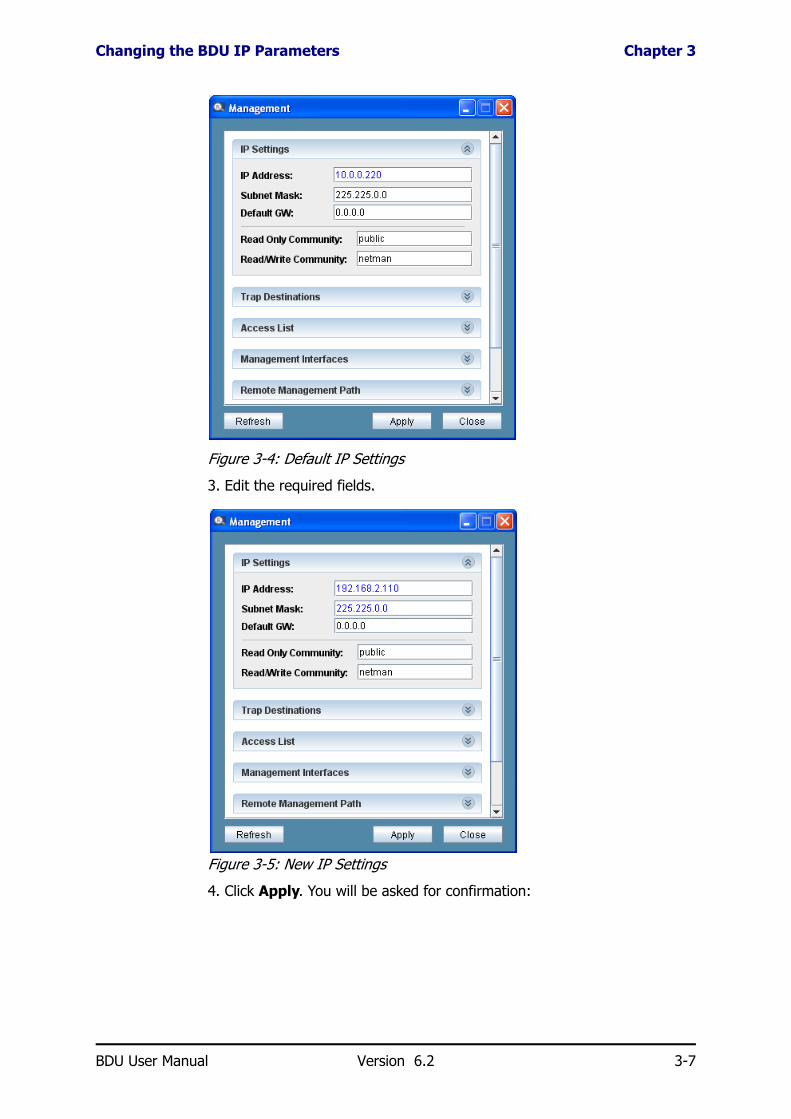
Changing the BDU IP ParametersChanging the device IP parameters is only possible at the Installer log on level.
To define device IP addresses:
1. From the BDU Manager main window, click Management. The Manage-ment window (Figure 3-5 below) appears
2. Click the IP Setting tab. The default IP settings are displayed:
Table 3-4: BDU Manager - Graphic symbols and colors
Ethernet Port Icons
Gray – No connection or link
Yellow – Ethernet Link without activity
Green – Ethernet Link with activity (Normal operation)
SFP PortIcons
Grey Empty – SFP plug-in is not detected
Grey – SFP plug-in detected
Yellow – Ethernet Link without activity
Green – Ethernet Link with activity (Normal operation)
BDU User Manual Version 6.2 3-6
Changing the BDU IP Parameters Chapter 3
Figure 3-4: Default IP Settings
3. Edit the required fields.
Figure 3-5: New IP Settings
4. Click Apply. You will be asked for confirmation:
BDU User Manual Version 6.2 3-7

Using the BDU Manager Dialogs Chapter 3
5. Click Yes. The following notice is displayed:
6. Click OK to complete the procedure.
Using the BDU Manager DialogsAll of the dialogs in the BDU Manager are similar to that shown in Figure 3-5. They are grouped functionally into panels. Figure 3-5 shows the Man-agement panel with the IP Settings dialog open.
The Apply button commits required changes for all of the dialogs in the panel. That is, you may enter data in one dialog and move to another with-out committing the data in the first. Apply will commit all new data for the whole panel after receiving confirmation:
The Close button applies to the whole panel. If you have dialogs with uncommitted data, you will be asked to confirm the close:
Refresh reverts all new uncommitted dialog data to their previous values, with the same warning as for Close.
If you intend to use more than one tab in a panel, you should consider using Apply repeatedly.
BDU User Manual Version 6.2 3-8

Management of the RADWIN BDU Chapter 3
To get the “effect” of the familiar GUI OK button, you must click Apply fol-lowed by Close.
To abbreviate verbose mouse-click sequences, we often use a convention as exemplified by the following: “On the main menu, click System followed by Environment” becomes, System | Environment. Such sequences are always shown in boldface type.
Management of the RADWIN BDUManagement of the BDU is divided into to types of configuration: Unit-wide parameters and defaults are set using the Manager Function panel of Figure 3-3 and is detailed in Chapter 4. Port-level parameters are config-ured by clicking the relevant port and are described in Chapter 5.
Note
• If you click Close in a panel without Apply, your changes for the whole panel will be lost
• Changed and uncommitted fields are displayed in blue. Clicking Apply will commit the new settings to the BDU. Once the BDU is updated, the field color will return to black.
• Several dialogs may be simultaneously open
BDU User Manual Version 6.2 3-9

Chapter 4
BDU Manager: UnitManagement
The description below follows the icon order in the left panel of the BDU Manager as shown in Figure 3-3.
SystemClick the System icon. The Properties window is displayed.
Properties
Figure 4-1: System Properties dialog
The Properties dialog displays the Device Description, Up Time and allows Name, Location and Contact information to be assigned to the device. Assigning those device details helps the system manager locate and identify
BDU User Manual Version 6.2 4-1

Inventory Chapter 4
devices in the network. It is recommended to assign such details to each unit.
InventoryThe Inventory dialog is for information only:
Environment
Figure 4-2: Environment dialog
The Environment dialog displays the current Operating Temperature of the BDU.
The temperature and internal 3.3 VDC voltage limits for the BDU define the alert thresholds. The limits can be modified by the Installer level user at any time.
BDU User Manual Version 6.2 4-2

Environment Chapter 4
The temperature thresholds should only be changed if the installation or operation environment requires it. The factory setup assumes operation in a 25°C environment.
The default temperature threshold is 60°C.
The default 3.3 VDC voltage threshold ranges between 3.15 V (low) and 3.45 V (high)..
To change the temperature or internal voltage limits:
1. Log on to the BDU Manager as Installer.
2. Click System | Environment. The System Configuration dialog (Figure 4-2) appears.
3. Click the Thresholds button.
Figure 4-3: Thresholds dialog
4. In the Thresholds dialog, enter the new Temperature threshold (only high limit) and/or Voltage thresholds and click OK.
NoteThe temperature thresholds can only be changed by an Installer.
Caution
• It is not recommended to change the default voltage thresholds.• Threshold alerts are only generated when the limits are crossed.
BDU User Manual Version 6.2 4-3

Factory Defaults Chapter 4
Factory Defaults
Figure 4-4: Factory Defaults dialog
To reload the BDU default parameters:
1. Log on to the BDU Manager as Installer.
2. Click System | Factory Defaults | Restore. A Verification prompt appears
3. Click Yes to confirm.
4. Restart the device, either through the Remote reset (see Commands below) or through Telnet (see Chapter 9) or by disconnecting and reconnecting the power.
5. The new settings will only become effective after a Reset.
CommandsThe only function available under this tab is Reset Device.
The reset process may take a minute or so during which you will not be able to connect to the device. (On the BDU itself, the FLT LED will turn red until completion of the reset.)
The BDU may be reset at any time. Reset is required, for example, after a new software version is uploaded.
To reset the BDU:
1. Log on to the BDU Manager as Installer.
2. Click the sequence: System | Command | Reset Device.
Note
• Factory defaults can be restored using Telnet.• Restoring the factory default settings will not affect the IP configura-
tions or the Get / Set Community settings.
BDU User Manual Version 6.2 4-4

Port Settings Chapter 4
3. Click Yes in response to the confirmation window.
Port SettingsUse this tab to determine which ports will be defined as ODU or AUX.
Figure 4-5: Port Settings with Port #1 opened for re-definition
Detailed per-port settings are carried out clicking individual Port icons. See Chapter 5.
Features
Global ConfigurationThis dialog sets Learning, Aging Time and Priority Policy.
The Ethernet switch Learning is always enabled and cannot be configured.
The BDU maintains an updated MAC address look-up table by continuously learning and flooding. The BDU can be configured to remove unused addresses or those that are not being used for a specified period (using aging time).
Each new look-up table entry is given a timestamp. Every time a packet is received from a node, the timestamp is updated. The entry is erased from the look-up table after the user configurable aging time with no activity from that network device (MAC address) has elapsed.
Setting too short an aging time can cause addresses to be prematurely removed from the table. Then when the BDU receives a packet for that des-tination, it floods the packet to all ports. This unnecessary flooding can impact the network performance. Setting too long an aging time can cause the address table to be filled with unused addresses; it can cause delays in establishing connectivity when a network device is moved to a different port.
Address migration capabilities – when a network device is moved to a dif-ferent port in the same BDU, the move is identified by the BDU after the first transmission from the network device is received. The MAC table is immediately updated with no relation to the aging time.
BDU User Manual Version 6.2 4-5

VLAN Configuration Chapter 4
Figure 4-6: Global Configuration dialog
In the Global Configuration dialog, aging can be configured as shown below (learning is always enabled).
To change the switch aging time:
1. Log on to the BDU Manager as Installer.
2. Click Features. |
3. In the Global Configuration dialog, click on the Aging value. The Aging value list appears.
4. Select the desired value.
Aging time can be set to 16 seconds, 300 seconds (5 minutes), 1800 sec-onds (30 minutes) or No Aging.
The factory default aging setting is 300 seconds.
VLAN ConfigurationStill inside the Features panel, the next five dialogs deal with various aspects of VLAN configuration. The BDU supports 802.1q VLAN and Port Based VLAN.
VLAN ModeVLAN Mode selects the VLAN operational scheme of the switch between VLAN Disabled (factory default), 802.1q VLAN and Port based VLAN.
To configure VLANs:
1. Do the detailed VLAN configuration using the relevant Tabs: 802.1q VLAN Membership, 802.1q Port Settings, Port Based VLAN and Transparent VID.
2. Enable the VLAN mode
The VLAN type must be selected from the VLAN Mode option.
Note
No Aging means the MAC addresses in the look-up table will not be removed automatically
BDU User Manual Version 6.2 4-6

VLAN Configuration Chapter 4
Figure 4-7: VLAN Mode dialog
802.1q VLAN MembershipThe 802.1q VLAN Membership dialog defines the VLAN IDs (VIDs) and the port membership for each of the VLANs. A BDU may be configured with up to 64 VLANs at a time, with VIDs ranging from 1 to 4095.
Figure 4-8: 802.1q VLAN Membership dialog
To configure VLAN membership
1. Click the sequence Features | 802.1q VLAN Membership.
2. Click the Add button. A prompt window will appear, requesting a New VLAN ID number. Enter a number not currently used by an existing VLAN, then click OK.
BDU User Manual Version 6.2 4-7
VLAN Configuration Chapter 4
3. The new VLAN appears on the 802.1q VLAN Membership dialog. Check all the ports to be included in the VLAN and then click Apply.
To delete a VLAN:
• Select that VLAN from the list in the 802.1q VLANs dialog and click Delete. The VLAN is deleted without a verification prompt.
To edit a VLAN:
• Simply click on the ports to add / remove from the VLAN (to check or uncheck them), then click Apply.
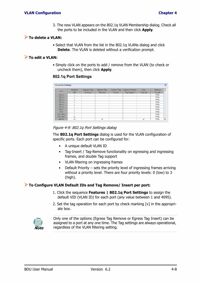
802.1q Port Settings
Figure 4-9: 802.1q Port Settings dialog
The 802.1q Port Settings dialog is used for the VLAN configuration of specific ports. Each port can be configured for:
• A unique default VLAN ID• Tag-Insert / Tag-Remove functionality on egressing and ingressing
frames, and double Tag support• VLAN filtering on ingressing frames• Default Priority – sets the priority level of ingressing frames arriving
without a priority level. There are four priority levels: 0 (low) to 3 (high).
To Configure VLAN Default IDs and Tag Remove/ Insert per port:
1. Click the sequence Features | 802.1q Port Settings to assign the default VID (VLAN ID) for each port (any value between 1 and 4095).
2. Set the tag operation for each port by check marking [v] in the appropri-ate box.
Note
Only one of the options (Egress Tag Remove or Egress Tag Insert) can be assigned to a port at any one time. The Tag settings are always operational, regardless of the VLAN filtering setting.
BDU User Manual Version 6.2 4-8

VLAN Configuration Chapter 4
T
To secure access from the managing computer:
• It is recommended to use VLAN filtering for the managing computer (referred to as MNGT).
Port Based VLANStatic VLAN assignments are created by assigning ports to a VLAN. With port-based VLAN membership, the port is assigned to a specific VLAN inde-
able 4-1: 802.1q VLAN Tag Configuration
Selected [ ] Deselected [ ]Ingress Tag Remove
Removes 802.3ac tag (or double tag) on tagged ingressing frames. Ingressing frames are not modified.
Egress Tag Remove
Removes tag from egressing frames. Frames are transmitted unmodified.
Egress Tag Insert Adds tag to untagged egressing frames (adds the default VLAN ID assigned to the port through which the frame entered the switch). Tagged frames are not modified.
Frames are transmitted unmodified.
Egress Double Tag Support
Double Tag on Egress. When Egress Tag Insert is selected, always adds a tag on egress. Tag will be added to both untagged frames and to tagged frames (double tag).
Double tag not active on egress.
VLAN Filtering Filters frames for the VLAN membership of the marked port. Frames are received unfiltered.
Note
• VLAN filtering operates on the port’s incoming and outgoing frames. A port whose VLAN Filtering is enabled will only forward a frame if it is a tagged frame of the VLAN that the port is a member of. A non-VLAN frame will be treated as if having the default VID of its ingress port.
• To avoid VLAN lockout, it is necessary to configure the VLAN mem-bership (using the 802.1q VLANs tab) before enabling the VLAN fil-tering.
• Frames without VLAN Tags or frames who's Tags are removed on Ingress (Ingress Tag Remove) will be filtered (if the VLAN filtering is enabled on both the switch and the specific port) according to the default VLAN ID (default VID) assigned to the originating port.
Note
• Operating management VLAN filtering requires that the management traffic on the network includes a management VLAN tag. This will avoid flooding the management by broadcast / multicast traffic through the BDU.
• If the management traffic does not include a VLAN tag, the manage-ment VLAN filtering can still be used by assigning a default VID, iden-tical to the defined management VLAN number, to the port from which the management traffic is received.
• MNGT VLAN filtering overrules Remote Management Path (see Chapter 6).
BDU User Manual Version 6.2 4-9

VLAN Configuration Chapter 4
pendent of the network device attached to the port. This means all devices attached to the port should be members in the same VLAN.
The port configuration is static and cannot be automatically changed to another VLAN without manual reconfiguration.
To Configure Port Based VLAN:
1. Click Features and open the Port Based VLAN.
2. Check the appropriate ports.
Figure 4-10: Port Based VLAN selection
Transparent VID
Figure 4-11: Transparent VID dialog
BDU User Manual Version 6.2 4-10

VLAN Management Grace Time Chapter 4
Transparent VID is a further enhancement to VLAN tag configuration. This function is useful to support an application or device that does not accept tagged frames on an otherwise tagged network.
The Transparent VID function defines a unique “transparent” VID to selected port(s). If the Egress Tag Insert is selected on those port(s) and Transparent VID is enabled, a tag will not be added to frames bearing the “transparent” VID when egressing. Those frames will be transmitted untagged while all other frames, bearing other VIDs, will be transmitted tagged.
To Configure Transparent VID:
1. Click Features and open the Transparent VID dialog.
2. Check Enable to activate the Transparent VID feature.
3. Enter the VID and check the appropriate ports.
VLAN Management Grace TimeAll RADWIN products supporting VLAN provide a two minute “grace time” after power-up to re-configure the BDU. It works like this:
1. For two minutes after power-up, you may re-configured the BDU in both VLAN and non-VLAN mode.
2. During this period, the BDU handles both VLAN and non-VLAN requests.
3. After two minutes, the BDU responds only to VLAN request
FilesSee Chapter 8, Updating Firmware.
Management
Management Interface Selection
To choose recognized management interfaces:
1. Log on as Installer.
2. Click Management | Management Interfaces. The following dialog appears:
BDU User Manual Version 6.2 4-11
License Chapter 4
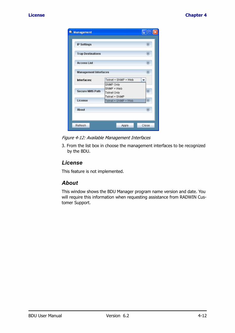
Figure 4-12: Available Management Interfaces
3. From the list box in choose the management interfaces to be recognized by the BDU.
LicenseThis feature is not implemented.
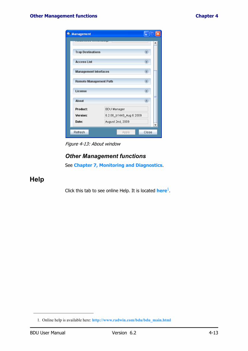
AboutThis window shows the BDU Manager program name version and date. You will require this information when requesting assistance from RADWIN Cus-tomer Support.
BDU User Manual Version 6.2 4-12
Other Management functions Chapter 4
Figure 4-13: About window
Other Management functionsSee Chapter 7, Monitoring and Diagnostics.
HelpClick this tab to see online Help. It is located here1.
1. Online help is available here: http://www.radwin.com/bdu/bdu_main.html
BDU User Manual Version 6.2 4-13

Chapter 5
BDU Manager: PortManagement
Port management is effected by clicking the relevant port icon on the main window of the BDU Manager. The appropriate Port Configuration window appears.
Figure 5-1: A typical Port Configuration dialog
Port TypesThe available configurable port parameters differ for the different type of ports.
Note
The available options vary for different type of ports. When an option is unavailable for the selected port type, the dialog will not be displayed.
BDU User Manual Version 6.2 5-1

ODU/AUX Ports Configuration and Status Chapter 5
The BDU includes four types of ports: ODU ports, AUX port, Uplink Ethernet ports and Uplink SFP ports:
• The ODU port is a 10/100BaseT RJ-45 port with fixed PoE forced on
• The AUX port is a 10/100BaseT RJ-45 port with 802.11af PoE func-tionality by default
• The Uplink Ethernet RJ-45 port is a 10/100/1000BaseT port
• The Uplink SFP port is a standard SFP GE port.
Within each Combo Uplink port only one port (Ethernet RJ-45 or SFP) can be active at one time according to the Preferred Media mode.
The Port View window consists of the following dialogs as described in Table 5-1 below:
ODU/AUX Ports Configuration and StatusThe Port View screen has information about the port, connection type and Status.
To view this information, click the Properties and Status tabs.
Table 5-1: Port View dialogs
Properties Displays port description and connection type.Assigns a name to a specific port.
Status Provides visual indications of port status and activity.The indicators include Link, Activity and Collision.
Administration Contains the port setup and operational status: speed, duplex, MDI and flow control settings.
Monitor Allows port monitoring to be enabled or disabled.
PoE Contains PoE setup and operational status.
MAC Security (Ethernet RJ-45 ports only) Allows individual ports to be disabled.
QoS (Ethernet RJ-45 ports only) Allows setting the Quality of Service parameters of the port.
Statistics Displays various statistics regarding traffic, port usage, and packets.
BDU User Manual Version 6.2 5-2

Configuring the Port Name Chapter 5
Figure 5-2: AUX/ODU port configuration – Properties and Status tabs
Configuring the Port NameEach port can be named in order to identify the user or device connected to it.
To configure a port name:
1. From the BDU Manager main window click the graphic of the port of interest. The Port View window appears.
2. From the Properties dialog of the Port View window, click the Name field.
3. Enter the port name and click OK.
Port SettingsThe ODU, AUX and Uplink Ethernet RJ-45 ports are factory preset with the following default values shown in Table 5-2:
Table 5-2: ODU, AUX and Uplink Ethernet RJ-45 default settings
Port Status On
Auto-negotiate Enabled
Speed Auto
Duplex Auto
MDI/MDIX Auto
Flow Control Enabled
PoE Force On (ODU ports), Off (AUX port)
BDU User Manual Version 6.2 5-3

Changing port settings Chapter 5
Changing port settingsThe port settings are configured from the Administration dialog. The dialog includes two columns, the Admin (Administrator) column and the Oper (Operational) column.
The setup is carried out in the Admin column while the actual operation mode is displayed in the Oper column.
Figure 5-3: Ethernet port configuration – Administration dialog
To change the port settings:
1. From the Port View screen, click the Administration tab.
2. Select the field to be changed. In it, select the new value for that field and click Apply.
Table 5-3: ODU, AUX and Uplink Ethernet RJ-45 Port Parameters
Parameter Description
Status Disables / Enables the port; Options: On, Off
Mode Port speed and duplex setting.
--Auto-negotiate – the port is set to negotiate speed and duplex with the link partner.
--Manual – speed and duplex are manually defined. Usually used when connecting to devices which do not support auto-negotiation or when link parameters must be forced.
Speed Applicable if auto-negotiation is set to Manual.
Options: 10M, 100M.
Duplex Applicable if auto-negotiation is set to Manual.
Options: Full duplex, Half duplex.
MDI/MDIX --Auto – Three negotiation advertise possibilities:
1) MDI and MDIX, 2) MDI, 3) MDIX
--Manual – Two possibilities: MDI or MDIX
Flow control Enables / Disables flow control.
BDU User Manual Version 6.2 5-4

Power over Ethernet (PoE) Chapter 5
Power over Ethernet (PoE)The BDU supports PoE on all ODU and AUX ports, with maximum PoE power capability of 13.75W per port (total 110W).
If a port is configured to operate in 802.3af mode, when an 802.3af pow-ered device is connected to the port, the port detects and classifies the device according to the 802.3af standard and activates the power accord-ingly. If the powered device is not 802.3af compliant, it will not be recog-nized and the port will not supply power to the device.
If a port is configured to operate in Force PoE On mode, 48V PoE power is always available.
The seven ODU ports are pre-configured to PoE Force On mode, while the AUX port can be configured to any of the PoE modes.
The monitoring and management of the PoE operation of the ODU/AUX ports is done from the PoE dialog in the Port View window.
PoE Management and Operation DialogFrom the PoE dialog select the PoE mode (status), configure the disconnect mode and monitor general PoE characteristics and power consumption.
The display will differ depending on whether the port is defined as ODU or AUX. For an AUX port, nothing may be changed:
Figure 5-4: Port View - PoE tab for an ODU port
NoteThe external power supply should be capable of providing at least 120W.
Warning
Care should be taken that only WinLink™ 1000 ODUs be connected to the ODU ports. Other devices connected to the ODU ports may be damaged.
BDU User Manual Version 6.2 5-5

PoE Management and Operation Dialog Chapter 5
Figure 5-5: Port View - PoE tab for an AUX port
Status: The left selection button selects the PoE operation mode (status) and the right button shows the operational status whether or not power is being supplied to the port.
The operational mode (status) can be selected between: Off; 802.3af On; Force On.
Figure 5-6: Port View window, PoE dialog, Mode/Status
An ON indication on the right Status list box appears when a device is detected and the power is provided to that port, or if the port is in PoE Force Open mode.
An OFF indication is when power is not provided to the port due to several possible reasons:
• The admin Status is OFF (PoE is disabled on the port)• Nothing is connected to an 802.3af port• The device connected to an 802.3af port is not an 802.3af compliant
device
Disconnect Mode (relevant when in 802.3af On): Selecting between AC Disconnect or DC Disconnect mode in the port configuration window. Selecting DC Disconnect will enable detection only of DC PDs (the most common type of PDs currently). Selecting AC Disconnect will enable detec-tion only of AC type PDs (mostly old PDs). The default is DC Disconnect.
Type/PD class: Indicates the PoE load type and class. If the PoE mode is “802.3af On”, it indicates the 802.3af power classifications of the device connected to the BDU port. If the PoE mode is “Force On”, it indicates “Not Available”.
BDU User Manual Version 6.2 5-6

QoS Chapter 5
Consumption: Displays the actual power being consumed by the powered device connected to the port.
Voltage: Displays the PoE voltage supplied to the port.
QoSThe packet flow through each port is defined by the Ingress / Egress Policy. The BDU provides three criteria that determine the policy, described in more detail below:
• QoS priority information
• Rate Limit
QoS Priority DefinitionsThe BDU uses an advanced non-blocking, four priority output port queue architecture. Frames exit the unit using a weighted, fair queuing scheme in which the weights 8, 4, 2, 1 are applied to the four priority output queues: eight frames from priority 3 egress, followed by four frames from priority 2, etc. Ingress frames are queued to the proper output queues according to their priority. The frame priority is determined either in the 802.3ac tag or in the TOS field.
Figure 5-7: Port View screen – QoS dialog
To define QoS priority criteria:
1. In the BDU Manager main window, click on the port of interest. The Port View window appears.
2. From the Port View window, click the QoS tab and set the port priority forwarding according to the following parameters.
• Ingress 802.3ac – Enables queuing of ingressing frames with 802.3ac tags containing 802.1p priority information to be queued accordingly
BDU User Manual Version 6.2 5-7

Rate Limit Definition Chapter 5
• Ingress ToS (Type of Service) - Enables queuing of ingressing frames with IPv4 TOS / DiffServ or IPv6 Traffic Class priority to be queued accordingly
Rate Limit DefinitionFrames enter (ingress) the port at the rate limit allocated to their identified priority level. Frames without a priority level, enter the switch at the rate limit assigned to the port (default PRI parameter). All frames exit (egress) the port at the Egress rate limit.
The BDU supports progressive Ingress rate limits for four priorities, where the rate for each priority level is relative to the previous level. Only Priority-0 is assigned a value.
For example, if Priority 0 rate is set to 8 Mbps, then priority 1 rate may be the same or double that of priority 0, priority 2 rate is the same or double that of priority 1, etc.
To define QoS Rate Limits:
• In the BDU Manager main window, click on the port of interest. The Port View window appears.
The QoS configuration options are shown in Table 5-4:
The BDU also supports different Rate limit criteria when counting packets. The switch can count all packets, broadcasts, multicasts and flooded uni-casts in various combinations.
If both Ingress IEEE 802.3ac and Ingress ToS are enabled, and a frame arrives with both types of priorities set, the frame will be queued according to the IEEE 802.3ac information.
Table 5-4: QoS configuration options
Rate limit parameters Available options
Egress rate Unlimited or Limited to one of the defined rates between 64Kbps to 80Mbps in 28 steps.
Ingress PRI 0 (low) Unlimited or Limited to one of the defined rates between 64Kbps to 80Mbps in 28 steps.
Ingress PRI 1 Same as PRI 0 or double (i.e. unlimited up to 160 Mbps depending on PRI 0 settings).
Ingress PRI 2 Same as PRI 1 or double (i.e. unlimited up to 320 Mbps depending on PRI 0 & 1 settings).
Ingress PRI 3 (high) Same as PRI 2 or double (i.e. unlimited up to 640 Mbps depending on PRI 0, 1 & 2 settings)
Note
It is recommended that Rate limit configuration of the BDU take into account the capacity of the radio links connected to it.
BDU User Manual Version 6.2 5-8

Combo Uplink Ports Status and Configuration Chapter 5
Figure 5-8: QoS dialog Rate Limit
To define the Rate Limit Criteria:
1. In the BDU Manager main window, click on the port of interest. The Port View window appears.
2. From the Port View window QoS dialog, click on the Rate Limit Criteria field and select the appropriate value from the list.
Figure 5-9: QoS dialog Rate Limit Criteria
Where -
Bcast – Broadcast
Mcast – Multicast
FUcast – Flooded Unicast
Combo Uplink Ports Status and ConfigurationEach Combo Uplink port includes an Ethernet 10/100/1000BaseT RJ-45 port and an SFP GE port. Only one can be linked and active at a time according to the Preferred Media mode.
The Port View screen has information about the Combo Uplink port, connec-tion type and Status.
To view this information, click the Properties and Status tabs.
BDU User Manual Version 6.2 5-9
Combo Uplink Port Administration Chapter 5
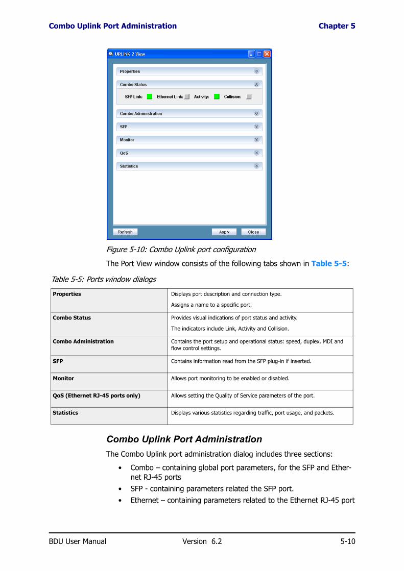
Figure 5-10: Combo Uplink port configuration
The Port View window consists of the following tabs shown in Table 5-5:
Combo Uplink Port AdministrationThe Combo Uplink port administration dialog includes three sections:
• Combo – containing global port parameters, for the SFP and Ether-net RJ-45 ports
• SFP - containing parameters related the SFP port.
• Ethernet – containing parameters related to the Ethernet RJ-45 port
Table 5-5: Ports window dialogs
Properties Displays port description and connection type.
Assigns a name to a specific port.
Combo Status Provides visual indications of port status and activity.
The indicators include Link, Activity and Collision.
Combo Administration Contains the port setup and operational status: speed, duplex, MDI and flow control settings.
SFP Contains information read from the SFP plug-in if inserted.
Monitor Allows port monitoring to be enabled or disabled.
QoS (Ethernet RJ-45 ports only) Allows setting the Quality of Service parameters of the port.
Statistics Displays various statistics regarding traffic, port usage, and packets.
BDU User Manual Version 6.2 5-10

Combo Uplink Port Administration Chapter 5
The Operational status (Oper) displays the status of the active port while the other port displays Not Established.
Figure 5-11: Combo Administration, SFP active port
Combo global Administration:
• Status: On or Off• Flow Control: Disable or Enable• Preferred Media: First, Fiber (SFP) or Ethernet RJ-45
Preferred Media selects which of the Combo ports will be “Linked” and have access to the switch.
First port – the first port that establishes a link. If both the SFP and the Ethernet ports are connected before power-up, usually the SFP will establish the first link because the Ethernet port has to go through the auto-negotiate process with its link partner.
Fiber (SFP) – Priority to the SFP port, the Uplink port will switch to the SFP port even if the Ethernet port was previously connected.
Ethernet – Priority to the Ethernet port, the Uplink port will switch to the Ethernet port even if the Ethernet port was previously connected.
SFP Administration:
• Mode: Auto-negotiate or Manual
• Speed: Always Gigabit (1000M)• Duplex: Always FDX
Ethernet Administration:
• Mode: Auto-negotiate or Manual• Speed: if in Manual - Auto, 10M, 100M, 1000M
BDU User Manual Version 6.2 5-11

SFP Information Chapter 5
• Duplex: if in Manual – HDX or FDX
Figure 5-12: Combo Administration, Ethernet active, Auto Negotiate
Figure 5-13: Combo Administration, Ethernet active, Manual
SFP InformationThe following information is read from the SFP:
Figure 5-14: SFP information, E1 type SFP
Figure 5-15: SFP information, LC type SFP
BDU User Manual Version 6.2 5-12

Chapter 6
SecuritySecuring Management Access
To avoid tedious repetition, it will be assumed that you are logged on to the BDU Manager as Installer.
There are three ways to remotely manage the BDU: through a Web browser, SNMP, or Telnet. The BDU provides various advanced methods for securing the remote management access. The management access security features, provided for the different management applications, are listed in Table 6-1 below:
Community String / PasswordsThe community string is a string of up to 15 alphanumeric characters, part of the SNMP packet. The SNMP agent in the BDU will respond only to SNMP packets whose community string matches that of its configuration. SNMP defines different community strings for Get and Set commands. The factory default community settings of the device are:
Table 6-1: Accessibility using different management methods
Methods of Security Management Web Management SNMP Telnet
Community Strings (SNMP)
Get Community and Set Community strings.Yes Yes --
User Access Levels
Three password protected user access levels.Yes --
Yes
(Single password)
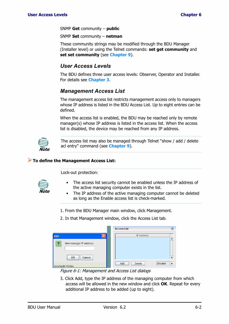
Management Access List
Restricts access only to managers whose IP address is defined on this list (white list).
Yes Yes Yes
Secure NMS Path
Restricts management access to specific ports.Yes Yes Yes
VLAN Secured Management
Assigns specific VLAN for management to isolate and secure management traffic and avoid management flooding by irrelevant traffic.
Yes Yes Yes
BDU User Manual Version 6.2 6-1
User Access Levels Chapter 6
SNMP Get community – public
SNMP Set community – netman
These community strings may be modified through the BDU Manager (Installer level) or using the Telnet commands: set get community and set set community (see Chapter 9).
User Access LevelsThe BDU defines three user access levels: Observer, Operator and Installer. For details see Chapter 3.
Management Access ListThe management access list restricts management access only to managers whose IP address is listed in the BDU Access List. Up to eight entries can be defined.
When the access list is enabled, the BDU may be reached only by remote manager(s) whose IP address is listed in the access list. When the access list is disabled, the device may be reached from any IP address.
To define the Management Access List:
1. From the BDU Manager main window, click Management.
2. In that Management window, click the Access List tab.
Figure 6-1: Management and Access List dialogs
3. Click Add, type the IP address of the managing computer from which access will be allowed in the new window and click OK. Repeat for every additional IP address to be added (up to eight).
Note
The access list may also be managed through Telnet “show / add / delete acl entry" command (see Chapter 9).
Note
Lock-out protection:
• The access list security cannot be enabled unless the IP address of the active managing computer exists in the list.
• The IP address of the active managing computer cannot be deleted as long as the Enable access list is check-marked.
BDU User Manual Version 6.2 6-2

Remote Management (NMS) Path Chapter 6
4. Verify that the IP address of the managing computer (issuing the com-mand) is on the Access List.
5. Click on the field at the bottom right, select Enable.
6. Click Apply. On the verification window that appears, click Yes.
To delete an address:
• Select the address from the list and click Delete.
Remote Management (NMS) PathThe in-band management path can be secured by limiting the remote access through either ODU/AUX ports, Uplink ports or all ports.
By default, the Remote Management path is not secured, allowing access from all ports.
To change the Remote Management Path:
1. From the BDU Manager main window, click Management.
2. In the Management window, Remote Management Path dialog, click on the selection box and select the desired option.
Figure 6-2: Changing the Remote Management Path
3. Click Apply.
• User Port(s) only – access is allowed only through the ODU/AUX ports (ports 1-8)
• Uplink Port(s) only – access is allowed only through the Uplink ports (1-2)
• All Ports – Secure NMS Path option is disabled and access is allowed through all ports
Securing Management Access using VLANSecuring management access using VLAN isolates and secures manage-ment traffic and avoids management flooding by irrelevant traffic.
You can assign a dedicated VLAN to the management traffic. Only frames belonging to that specific VLAN, received from ports belonging to the same VLAN membership group, can communicate with the managing computer.
NoteMGMT VLAN filtering (see Chapter 4) overrules Remote Management Path.
BDU User Manual Version 6.2 6-3
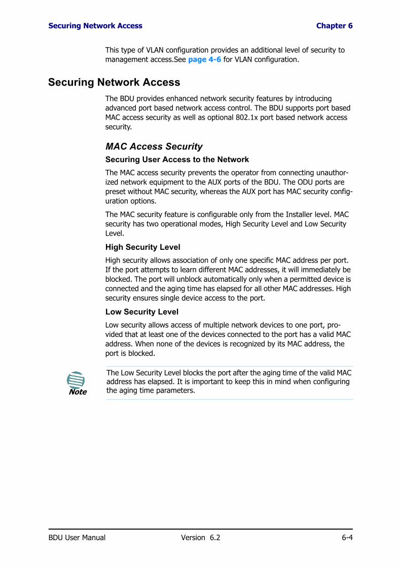
Securing Network Access Chapter 6
This type of VLAN configuration provides an additional level of security to management access.See page 4-6 for VLAN configuration.
Securing Network AccessThe BDU provides enhanced network security features by introducing advanced port based network access control. The BDU supports port based MAC access security as well as optional 802.1x port based network access security.
MAC Access SecuritySecuring User Access to the NetworkThe MAC access security prevents the operator from connecting unauthor-ized network equipment to the AUX ports of the BDU. The ODU ports are preset without MAC security, whereas the AUX port has MAC security config-uration options.
The MAC security feature is configurable only from the Installer level. MAC security has two operational modes, High Security Level and Low Security Level.
High Security LevelHigh security allows association of only one specific MAC address per port. If the port attempts to learn different MAC addresses, it will immediately be blocked. The port will unblock automatically only when a permitted device is connected and the aging time has elapsed for all other MAC addresses. High security ensures single device access to the port.
Low Security LevelLow security allows access of multiple network devices to one port, pro-vided that at least one of the devices connected to the port has a valid MAC address. When none of the devices is recognized by its MAC address, the port is blocked.
Note
The Low Security Level blocks the port after the aging time of the valid MAC address has elapsed. It is important to keep this in mind when configuring the aging time parameters.
BDU User Manual Version 6.2 6-4

MAC Access Security Chapter 6
Figure 6-3: AUX Port View Window, MAC Security dialog
ODU ports are configured with MAC security level.
Figure 6-4: ODU Port View Window, MAC Security
MAC Security Configuration Fields:
Mode displays the MAC security operational mode (disabled, low security or high security).
Status displays the port security status (disabled, port forwarding, or port blocked). When Disable appears in the Status field, this means that the MAC security is disabled. When Port Forwarding or Port Blocked appears in the Status field, this means that the MAC security is enabled and that the specific port is either forwarding or blocked according to the MAC security configuration.
MAC Address 1-3 list displays MAC addresses that can be selected as the valid MAC address.
Approved MAC field displays the MAC address to be secured.
BDU User Manual Version 6.2 6-5
MAC Access Security Chapter 6
Figure 6-5: AUX Port View - MAC Security dialog and Approved MAC selec-tion
To Configure MAC Access Security (AUX port):
1. In the BDU Manager main window, click on the AUX port. The Port View window appears. Click the MAC Security tab.
2. In the Approved MAC list select the MAC Address to be the valid MAC address.
3. Open the Mode list and set the mode according to the following parame-ter descriptions and click Apply.
• Disable – MAC security is disabled.• Low Security Level.• High Security Level.
Note
Port Monitoring, MAC security and 802.1x cannot be active at the same time.
Note
Port blocking through MAC Security is indicated as a major event and an appropriate trap is sent accordingly.
BDU User Manual Version 6.2 6-6

Chapter 7
Monitoring andDiagnostics
To avoid tedious repetition, it will be assumed that you are logged on to the BDU Manager as Installer.
Unit and Port Level DiagnosticsThe BDU provides monitoring and diagnostics functions at both system and port level:
• System level – The last 64 events are stored. The events display can be filtered according to user defined criteria. A red bell icon on the BDU Manager main screen provides notification of a new event. The system reports two levels of events: Notify and Major. Major events also generate a pop-up dialog box. Events may be acknowl-edged by an Administrator level user. Only events occurring on the network ports of the BDU are recorded. Configuration changes that are initiated by the network manager are not considered events. Events can also be sent as SNMP traps to additional destinations by adding their IP addresses to the BDU’s SNMP Trap Destination List.
• Port level – Monitoring and analysis includes port specific RMON statistics, counters and port monitoring.
SNMP Trap DestinationsWhen a system event is detected, the BDU sends a trap to a list of destina-tions.
To configure the SNMP Traps destination addresses:
1. In the BDU Manager main window, click Management.
2. In the Trap Destination dialog, click Add.
NoteThe Trap destination list may be configured through Web, Telnet and SNMP.
BDU User Manual Version 6.2 7-1

Events Log Chapter 7
Figure 7-1: Management menu, SNMP Traps and Add dialog
3. In the IP address box, enter a traps destination IP address.
4. Click OK. The address will appear in the IP address list.
5. Repeat for steps 1 to 4 each additional IP address.
To remove a traps destination address:
• Select the address and click Delete.
Events Log
Viewing Recorded EventsThe last 64 events are stored in the BDU and are available for display at any time through the Events Log window. The Events list is cleared when the device is turned off or reset.
The BDU Manager displays an unlimited number of events. If it disconnects from the BDU and reconnects, only the last 64 events that are stored in the BDU are available in the Events Log.
Only events occurring on the network ports of the BDU are recorded. Con-figuration changes that are initiated by the BDU Manager are not considered as events.
The viewed events may be acknowledged and filtered according to various user defined criteria. The events recorded are:
Major Events:• Device voltage: changes that exceed the thresholds and return to
within limits (see page 4-3)
• Internal temperature: changes that exceed the thresholds and return to normal (see page 4-2)
• Port Locked due to security definitions: when an unauthorized MAC address attempts to connect to a MAC Secured port (see page 6-4)
Notify Events:• Change in Port status: Link up, Link down• System status
BDU User Manual Version 6.2 7-2

Viewing Recorded Events Chapter 7
To view the full Events Log window:
• The Events Log is visible on the bottom part of the BDU Manager main window. To expand it, click on the arrow button on its top right corner.
Figure 7-2: Events Log window
Each trap notification consists of:• A unique index number• Event date and time stamp
• Event description• Event source• Severity (notify, major)
• Acknowledge (yes or no)
Event Levels and Color codes:The record is colored according to its severity:
• Notify (cyan) • Major (red)
To Sort information:
• From the Events Log window, click any header to sort the information according to the selected header in ascending or descending order.
To acknowledge events:
• From the expanded Events Log window, select the requested event(s) in the table and click the Ack on the bottom right.
NoteOnly Installer level users can acknowledge events.
BDU User Manual Version 6.2 7-3

Events Filter Chapter 7
Events Filter
Figure 7-3: Events Filter window
The display of events may be filtered according to different parameters to help the network manager focus on specific issues.
The available filters are: Date, Time, Port Number (source of trap), Severity and Acknowledged / Unacknowledged events.
To filter the displayed events:
1. From the BDU Manager main window, click the expansion tab at the right hand side of the Events title bar. The Events log covers the main window of the manager exposing Filter and Acknowledge buttons along the bottom.
BDU User Manual Version 6.2 7-4
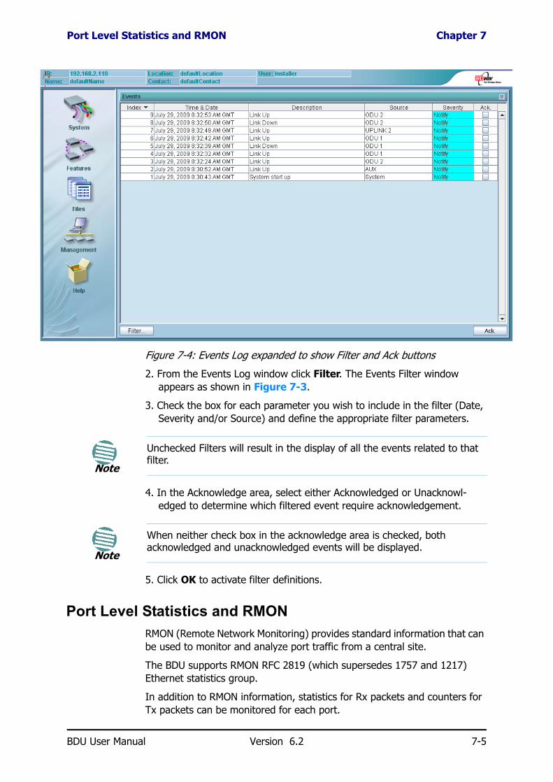
Port Level Statistics and RMON Chapter 7
Figure 7-4: Events Log expanded to show Filter and Ack buttons
2. From the Events Log window click Filter. The Events Filter window appears as shown in Figure 7-3.
3. Check the box for each parameter you wish to include in the filter (Date, Severity and/or Source) and define the appropriate filter parameters.
4. In the Acknowledge area, select either Acknowledged or Unacknowl-edged to determine which filtered event require acknowledgement.
5. Click OK to activate filter definitions.
Port Level Statistics and RMONRMON (Remote Network Monitoring) provides standard information that can be used to monitor and analyze port traffic from a central site.
The BDU supports RMON RFC 2819 (which supersedes 1757 and 1217) Ethernet statistics group.
In addition to RMON information, statistics for Rx packets and counters for Tx packets can be monitored for each port.
Note
Unchecked Filters will result in the display of all the events related to that filter.
Note
When neither check box in the acknowledge area is checked, both acknowledged and unacknowledged events will be displayed.
BDU User Manual Version 6.2 7-5

Port Monitoring Chapter 7
To display the port RMON information, Rx statistics and Tx counter:
1. From the BDU Manager main window, click the icon of the port of inter-est. The Port View window appears.
2. From the Port View window, select the Statistics dialog as shown in Figure 7-5 below:
Figure 7-5: Port Statistics and Counters
Port MonitoringThe port monitoring feature enables analyzing and recording valid data on a port by mirroring its traffic to a second user allocated (monitoring destina-tion) port. You may monitor the egress, or both ingress and egress data of any port. This feature can be used for network analysis as well as recording port traffic.
You can monitor more than one port on a single monitoring destination port.
The monitoring port bandwidth is limited to the destination port bandwidth. Therefore, to ensure the integrity of the monitored data, flow control is automatically activated on the monitored port(s) as soon as the monitored traffic exceeds the destination’s port bandwidth.
To configure port monitoring:
1. From the BDU Manager main window, click on the port to be monitored. The Port View window appears.
2. From the Port View window, click the Monitor tab.
BDU User Manual Version 6.2 7-6

Port Monitoring Chapter 7
3. Select the Port Monitoring Mode from the Mode list according to the description in Table 7-1:
4. Select the destination port from the Destination list and click Apply.
Figure 7-6: Port View window, ODU1 port Monitor dialog
Table 7-1: Port monitoring modes
Option Description
No Port monitoring mode not enabled.
Egress Only Only egress frames are copied to the destination port.
When the device is reset, the monitoring mode resets to None.
Egress & Ingress Egress and ingress frames are copied to the destination port. When the device is reset, the monitoring mode resets to None.
NV Egress Only Only egress frames are copied to the destination port.
Mode remains on after system reset.
NV Egress & Ingress Egress and Ingress frames are copied to the destination port.
Mode remains on after system reset.
BDU User Manual Version 6.2 7-7

Chapter 8
Updating FirmwareTo avoid tedious repetition, it will be assumed that you are logged on to the BDU Manager as Installer.
Firmware componentsThe BDU firmware comprises of three elements, each of which, may be updated separately:
• Image – SNMP Agent software
• Content – Java Applet (Web management interface)• Config – Saved configuration template that may be loaded to a BDU
Figure 8-1: Files menu
BDU User Manual Version 6.2 8-1

Management Firmware Update Chapter 8
Management Firmware UpdateTo update the firmware:
1. From the BDU Manager main window click on the Files button.
2. In the File Server dialog, update the IP address of the TFTP File Server that will be used to download new firmware versions to the device (The specified IP must have a running TFTP server).
3. In the Operation dialog, update the file name of the new firmware ver-sion you wish to download to the device.
4. Select the desired operation from the Command list. Be sure to match the file type with the command (.bin with Download Image, .con with Download Content).
5. While downloading / updating the image and content files (this may take several minutes) the Status field will change depending on the current operation being executed. At the end of the process, that field will update again to announce the success or failure of the update.
Uploading and Downloading Configuration FilesThe BDU supports download and upload of pre-built configuration files.
The files are intended to assist configuration of a large number of devices to identical settings.
Downloading or uploading the configuration files is carried out the same way as the Firmware update, described in the previous section.
Note
To perform a download or upload operation, the command being executed must be colored blue, indicating a changed setting. Clicking Apply without changing the Command, even if it was set in advance, will do nothing.
Note
Each file downloads separately. After downloading one file, repeat steps 3 and 4 in order to download the next file.
Note
Performing an upload operation with no configuration file loaded will result in a new configuration file being created on the server. Set the file name before uploading. The file extension is not important.
BDU User Manual Version 6.2 8-2

Chapter 9
TelnetGeneral
Telnet enables remote management of a BDU. Configuration of multiple BDUs may be accomplished by running telnet script files created for that purpose.
Using TelnetTo run Telnet
1. From a command line, type telnet followed by a space then type the IP address of the target device (exact syntax according to the operating system). The prompt Welcome to BDU Manager; Please enter log on password appears.
2. At the prompt, enter the password, mypass. Note that the password is case sensitive. The device prompt, BDU> appears. The device is ready to receive Telnet commands (see figure 9-1, BDU Telnet Commands).
Invoking Telnet HelpAt the Telnet prompt -
• To view the list of available commands, type ? or help and press Enter.
• To invoke help on a specific command, type the command, followed by a space and ?
Here is the list of available Telnet commands:
Note
For security reasons, the Telnet session will automatically terminate if there is no telnet activity for approximately 60 seconds
BDU User Manual Version 6.2 9-1

Using Telnet to Change User Level Passwords Chapter 9
Figure 9-1: BDU Telnet Commands
Using Telnet to Change User Level PasswordsTo Change User Level Passwords
1. Log on to telnet as described in Using Telnet above.
2. Type the command set http password followed by a space then any of the user level access words you wish to change (tech, admin, or guest) and then followed by another space and the new password you want to assign to that user level, then press enter. A user level pass-word has now been changed. Changing passwords for one user level does not effect the other user level passwords.
Note
To see the user names and passwords up to the current level, type show http password followed by a space and a question mark (?)
BDU User Manual Version 6.2 9-2

Appendix A
Technical SpecificationsODU Interface
Uplink Interface
All Interfaces
Management
Number of ODU Ports 7 + 1AUX (Port #8) 802.3af default, can be configured to ODU portConnector RJ-45
Interface Two Combo port of 10/100/1000BaseT or SFPSFP Types Standards: 1000BaseT IEEE 802.3, 1000Base-x IEEE 802.3 and G.703 (E1/T1)SFP Modes Auto Negotiation and Manual FDConnector RJ-45
Line Impedance 100ΩFraming/Coding IEEE 802.3/UMaximum Frame Size 1632 BytesMAC Address Table Size 8K addresses
VLAN802.1q supported; 64 VLAN IDs per portTagging/Un-tagging per port
QoSIEEE 802.1p 4 priority queuesToS support
Rate Limiting
Ingress and Egress Based64Kbps to 2M (64K resolution)2M to 10M (2M resolution)10M to 50M (5M resolution)50M to 100M (10M resolution)
Security SSL, Access control List
Web Based Management Microsoft Internet Explorer, Mozilla Firefox, Google ChromeProtocol SNMP v1/ SNMP v2 IP Address Assignment Configurable or by DHCPSoftware Upgrade Web-based
BDU User Manual Version 6.2 A-1

Mechanical Chapter A
Mechanical
Power
Environmental
Safety
EMC
Dimensions 48.3cm(W) x 29cm(D) x 4.5cm(H)Weight 1.5 kg / 3.3 lbs
Power Feeding 0.2Amp @ -48VDC; (Feeding each ODU requires additional 0.2Amp) Max Power Dissipation 10Watt
Operating Temperatures 0°C - 45°C / 32°F - 113°FHumidity 90% non-condensing
UL/TUV 60950 (Third Edition)EN IEC 60950-1 (2001)CAN/CSA C22.2 No. 60950
FCC 47 CFR Class B, Part15, Subpart BEN 300 386 V1.3.2; 301 489-4 V1.3.1; 301 489-1 V1.4.1CAN/CSA-CEI/IEC CISPR 22-02
BDU User Manual Version 6.2 A-2

Appendix B
Wiring SpecificationsODU-BDU Cable
The ODU-BDU cable is shielded/outdoor class CAT-5e, 4 twisted-pair 24 AWG terminated with RJ-45 connectors on both ends. A cable gland on the ODU side provides hermetic sealing.
ODU - BDU Ethernet RJ-45 Port ConnectorsThe following table shows the ODU-BDU connector pinout:
Note
The ODU-BDU cables are identical to the ODU-IDU cables in the RADWIN Products Catalog.
Table B-1: ODU-BDU RJ-45 Connector Pinout
Function Color BDU ODU
Ethernet (RxN) White/Green 1 1
Ethernet (RxT) Green 2 2
Ethernet (TxT) White/Orange 3 3
Ethernet (TxN) Orange 6 6
Power (+) Blue 4 4
Power (+) White/Blue 5 5
Power (−) White/Brown 7 7
Power (−) Brown 8 8
Note
Ethernet ports that support PoE use pairs for data and pairs for power as in Table B-1. Since an ODU can be connected to AUX port, the latter has the same pinout as the ODU ports and is included in Table B-1. Since only two pairs are used for data, the port is limited to 100Mbps making it a 10/100baseT
BDU User Manual Version 6.2 B-1

Uplink Ethernet RJ-45 Port Connectors Chapter B
Uplink Ethernet RJ-45 Port ConnectorsThe Uplink Ethernet RJ-45 10/100/1000BaseT interface terminates in an 8-pin RJ-45 connector, wired in accordance to Table B-2.
DC Power Terminal
Table B-2: Uplink Ethernet Connector Pinout
Pin Signal Function
1 BI_DA+ Transmit Data
2 BI_DA- Receive Data
3 BI_DB+ Transmit Data
4 BI_DC+ Transmit Data
5 BI_DC- Receive Data
6 BI_DB- Receive Data
7 BI_DD+ Transmit Data
8 BI_DD- Receive Data
Note
10/100/1000baseT ports support 1000bps using four pairs hence cannot support power. This is applies to the Uplink Ethernet RJ-45 port as shown in Table B-2.
Table B-3: Terminal Block 3-pin -48VDC
Function Pin
+ Right
Chassis Center
– Left
BDU User Manual Version 6.2 B-2

Index
IndexNumerics802.1q
Port Settings 4-8VLAN Membership 4-7, 4-7
802.3ac, ingress frames 5-7
AAccess Lists 6-1, 6-2Address migration 4-5Aging Time 4-5, 4-5, 4-6Auto-Negotiation 1-4, 1-4, 5-3, 5-4, 5-4, 5-11, 5-11,
5-11
BBackbone, see UplinkBase Distribution Unit = BDU 1-1BDU
Everything refers to unless otherwise indexedBDU Manager
dialogs, using 3-8Graphic symbols and colors 3-6Launching 3-1Left Function Panel 3-5Log on 3-2Main window 3-4Pre-requisites for 3-1
CCables and connectors 2-2Combo, see Uplink portsCommands 4-4Community Strings 1-5, 3-3, 4-4, 6-1, 6-1Configuration
Global 4-5Ports, ODU, AUX 5-2Uplink ports 5-9VLAN 4-6
ConnectingODU 2-5user equipment 2-5
Copper, see Ethernet
DDC power socket 2-4, 2-5Defaults
3.3 VDC voltage threshold 4-3Aging Time 4-6device 3-2, 3-3factory 4-4IP address 3-1temperature threshold 4-3user names and passwords 3-3
Description of 2-1
Eegress 4-9, 4-11, 5-8, 7-6, A-1
frames 4-8monitoring 7-7policy 5-7QoS (Quality of Service) options 5-8rate limit 5-8tag 4-9
Environment 4-2
FFactory Defaults 4-4Files 4-11forced on 1-4, 5-2Foreign devices
Connectivity blocked 2-5damage 2-5
Front Panel 2-3
GGlobal Configuration 4-5grace time at power-up 4-11Grounding Lug 2-4
Iingress 5-7, 5-7, 7-6, A-1
frames 4-8, 4-8, 5-7, 5-7802.3ac 5-7
monitoring 7-7policy 5-7
BDU User Manual Version 6.2 Index 1

port 4-9QoS (Quality of Service) options 5-8rate limiting 5-8tag 4-9ToS (Type of Service) 5-8
InstallationHardware 2-3
Inventory 4-2IP address 3-1, 6-1, 6-1, A-1
approved 1-5default 3-1, 3-1, 3-3defining 3-6management access 6-2managing computer 6-2SNMP trap 7-2Telnet 9-1TFTP File Server 8-2trap destination 7-1
JJava
Where to get JRE 3-1
LLEDs 2-4, 2-4Lock-out 6-2
MManagement 4-11
Access 6-1MNGT, see VLAN filtering 4-9Mounting 2-3
NNMS Path 6-1, 6-3
OODU
connecting to 2-5Operating Temperature 4-2
PPackage Contents 2-1Pictures of
photographschematics
PoE 1-3, 1-4, 1-4, 5-5, 5-6, 5-6Consumption 5-7Disconnect Mode 5-6forced on 1-4, 5-2, 5-2, 5-3Management, operation 5-5Type/PD class 5-6Voltage 5-7
PortsDisconnect Mode 5-6ingress 4-9
Name 5-3Settings 5-3
portsAUX 2-4, 3-4, 5-2, 5-2, 5-3, 5-3, 5-5, 6-4, 6-4, 6-
5, 6-6Configuration, status 5-2
Auxiliary, see ports, AUXODU 1-3, 1-4, 2-3, 2-4, 3-4, 5-2, 5-2, 5-3, 5-3,
5-5, 6-4, 6-5, A-1ODU, foreign devices 2-5types and description 5-2Uplink Ethernet 5-2Uplink SFP 5-2
Power connector and LEDs 2-4, 2-5Powering up 2-5Power-over-Ethernet, see PoE 1-1Priority Policy 4-5Properties 4-1
QQoS
described 5-7Priority Definitions 5-7
RRate Limit Definition 5-8
SSafety Practices
General 2-1Grounding 2-1
SFP 1-4, 1-4, 1-5, 2-4, 3-4, 3-6, 5-2, 5-9, 5-10, 5-10, 5-12, A-1
SNMP 1-3, 1-5, 3-1, 6-1, 6-1, 7-1, 8-1, A-1and traps 7-1
System 4-1
TTechnical Specifications A-1Telnet 1-3, 1-5, 3-1, 3-3, 4-4, 6-1, 6-2, 6-2, 7-1Temperature threshold,default 4-3Thresholds, setting 4-3Tools and Materials 2-2
UUplink
RJ45 pinout B-2Uplink ports 1-4, 2-4, 2-4, 5-9, 6-3, A-1
Administration 5-10, 5-10, 5-12Combo, configuration, status 5-9Ethernet 5-11Fiber 5-11First port 5-11Limitations on use 2-6Preferred Media 5-11SFP Administration 5-11
BDU User Manual Version6.2 Index 2

VVID, transparent 4-11VLAN
Add, delete, edit 4-8Configuration 4-6filtering 4-8, 4-9ID, transparent 4-11IDs = VIDs 4-7lockout 4-9membership 4-9Membership, 802.1q 4-7Mode 4-6Port Based, ff 4-9Power-up grace time 4-11secure management access 6-3Tag-Insert/Remove 4-8
Voltage threshold,default 4-3
WWiring Specifications B-1
ODU-BDU Cable B-1
BDU User Manual Version6.2 Index 3