Embed Size (px)
Citation preview

This is a
CAT II2H3+
appliance
USER, INSTALLATIONAND SERVICINGINSTRUCTIONS
Wall hungcombination boilers
SUPPORTED BY
2 iconIndex
Note
The boiler serial number is marked on the data label attached to the inside of the outercasing. Refer to the ‘Introduction’ section for a description of the basic functions of the boiler.The ‘User’ section describes how to safely operate the boiler.
Mandatory warning for CEE countries
WARNING , these appliances were designed, approved and inspected to meet therequirements of the English market. The identification plate located on the inside of theappliance certifies the origin where the product was manufactured and the country forwhich it is intended.
If you see any exception to this rule, please contact your nearest Stockist.
Thank you in advance for your assistance.
Index
Introduction .......................................... 3
Userinstructions ..................................3
Introduction .......................................... 4Controls and lighting ............................. 4
Technical data ..............................7
Installationinstructions ................................11
Clearances ......................................... 11Terminal position ................................ 12Heating system design ....................... 13Domestic hot water system design..... 13Boiler connections .............................. 14
Gas connection .................................. 14Boiler installation ................................ 15Horizontal flue installation .................. 16Vertical flue installation ....................... 17Flue configuration ............................... 18Electrical connection .......................... 19Commissioning ................................... 20Safety devices .................................... 22Gas valve setting ................................ 23Adjustments ....................................... 23Boiler schematic ................................. 25
Servicinginstructions ................................26
Routine cleaning and inspection ......... 27Replacement of parts ......................... 28Schematic wiring diagram .................. 31

3icon User instructions
IntroductionThe icon 23 t and icon 28 t boilers are wall mounted combination boilers providing centralheating and instantaneous domestic hot water.
The boilers are of the II2H3+ category for use with Natural gas (G20) as distributed in the UnitedKingdom.
These instructions should be carefully followed for the safe and economical use of your boiler.
The boiler has a fan assisted balanced flue which both discharges the product of combustion to,and draws the combustion air from the outside of the building.
ACCESSORIES
A range of accessories are available including vertical flue components. For further information,contact you nearest Stockist.
GAS SAFETY (INSTALLATION AND USE) REGULATIONS
In your interests and that of gas safety, it is the law that ALL gas appliances are installed andserviced by a competent person in accordance with the above regulations.
GAS LEAK OR FAULT
If a gas leak or fault exists or is suspected, turn the boiler off and consult the local gas company oryour Installer/Service Provider.
BOILER CONTROLS
The control panel, located at the lower front of the boiler, allows the boiler to be started, shut down,controlled and monitored during use, refer to ‘User Instructions’.
Userinstructions
4 iconUser instructions
IntroductionThe icon 23 t and icon 28 t boilers are wall mounted combination boilers providing centralheating and instantaneous domestic hot water.
These instructions should be carefully followed for the safe and economical use of your boiler.
GAS LEAK OR FAULT
If a gas leak or fault exists or is suspected, turn the boiler off and consult the local gas company oryour Installer/Service provider.
IN CASE OF POWER SUPPLY FAILURE
The boiler no longer operates.
As soon as power supply is restored, the boiler will restart automatically.
IN CASE OF LOSS OF WATER IN THE SYSTEM
CAUTION: The boiler is installed as part of a sealed system which must only be drained andfilled by a competent person.
If the pressure shown on the pressure gauge is less than 1 bar the system must be filled upimmediately.
Important notice: A central heating system cannot operate satisfactorily unless it is properly filledwith water and unless the air initially contained in the piping systems has been properly bled off. Ifthese conditions are not satisfied, air noise will occur within the system.
AIR IN THE HEATING SYSTEM
Persistent air in the heating system may indicate leaks in the system or corrosion taking place. Callyour Installer/Service provider.
OVERHEATING SAFETY
In the event of problem, the overheat safety device causessafety shutdown of the boiler. If this happens, call your In-staller/Service provider.
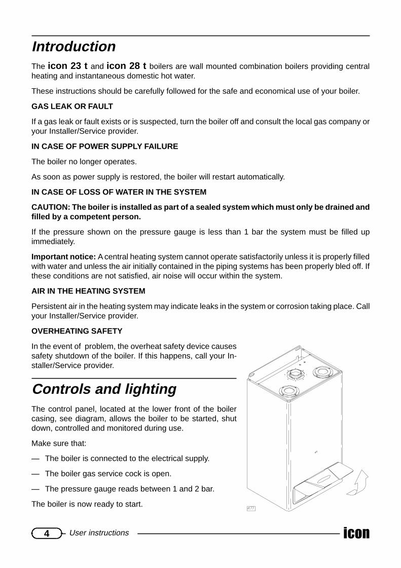
Controls and lightingThe control panel, located at the lower front of the boilercasing, see diagram, allows the boiler to be started, shutdown, controlled and monitored during use.
Make sure that:
— The boiler is connected to the electrical supply.
— The boiler gas service cock is open.
— The pressure gauge reads between 1 and 2 bar.
The boiler is now ready to start.

5icon User instructions
Controls1 Safety lockout light2 Summer/Winter switch3 Heating temperature control4 Hot water temperature control5 Pressure gauge6 Timeclock7 Plastic toggles
TO START THE BOILER
Turn selector (2) to the desired Summer or Winter position.
The green lamp will light.
TO STOP THE BOILER
Turn selector (2) to the OFF position (0).
If the boiler is to be out of operation for a long period, turn off the gas service cock.
SETTING TO ‘SUMMER’ MODE (HOT WATER ONLY)
Turn selector (2) to the Summer position .
Adjust the domestic hot water control (4) to the desired hot water temperature. The boiler willoperate according to the system requirements.
SETTING TO ‘WINTER’ MODE (HEATING AND HOT WATER)
Turn selector (2) to the Winter position .
Adjust the heating temperature control (3) to the desired temperature.
Adjust the domestic hot water control (4) to the desired hot water temperature. The heatingwill operate according to the requirements of the timeclock and room thermostat if fitted or, willoperate according to the system requirements.
Domestic hot water always has priority over central heating.
TO PROGRAM DAILY TIMECLOCK (6) (WINTER MODE ONLY)
Set the current time, by turning the dial clockwise until the current time is shown against theindicator “ ”.
Push in plastic toggles (7) against the time you wish the heating to come on.
The timeclock can operate in three positions: automatic “ ”, heating off “0”, and heating on “1”.
To select, move the lever to the desired position.
NOTE: In case of failure of electrical supply, timeclock does not operate, having no back-up bat-tery. Therefore it will be necessary to adjust the current time, once electrical supply is restored.

6 iconUser instructions
SAFETY LOCKOUT
If, for any reason, the boiler does not operate, check if lockout lamp (1) is lit. If so, turnselector (2) to the reset position . The selector is spring loaded and automatically returns toits’ previous position when released.
Note: This lamp will only light if the boiler has locked out and there is a hot water or central heatingdemand at that particular time.
IMPORTANT: If the safety lockout lamp lights frequently, contact your Installer/Service Pro-vider.
DRAINING AND FILLING
CAUTION: The boiler is installed as part of a sealed system which must only be drained andfilled by a competent person.
Note: If there is persistent loss of system pressure, you must consult your Installer/Service Pro-vider.
HEATING SAFETY VALVE
CAUTION: A safety valve with a discharge pipe is fitted to this boiler.
The valve MUST NOT BE TOUCHED except by a competent person. If the valve discharges at anytime, switch the boiler off and isolate it from the electrical supply. Contact your Installer/ServiceProvider.
SERVICING/MAINTENANCE
To ensure the continued efficient and safe operation of the boiler, it is recommended that it ischecked and serviced at regular intervals. The frequency of servicing will depend upon the instal-lation conditions and usage but, in general, once a year should be enough.
CLEANING
The boiler casing can be cleaned with a damp cloth followed by a dry cloth to polish.
Do not use abrasive or solvent cleaners.
BOILER CASING
CAUTION: Do not remove or adjust the casing in any way, as incorrect fitting may result infaulty operation.
If in doubt, contact your Installer/Service Provider.

7icon Technical data
Technicaldata

8 iconTechnical data
ATADLACINHCET tinU t32noci t82noci
noitacifitreCEC °n 7424TA3600 5992LB4960ssalC +3H2II
epyT 28-26-25-24-23-21CepyTsaG 02G
)sH(tupnItaeH.xaM Wk 4.82 53)sH(tupnItaeH.niM Wk 6.11 51
)iH(tuptuOtaeH.xaM Wk 3.32 1.82)iH(tuptuOtaeH.niM Wk 7.8 11
YCNEICIFFEycneiciffelanimoN % 29 3.29
daol%03taycneiciffE % 4.78 09
GNITAEHegnarerutarepmeT C° 58-04 58-04
lessevnoisnapxE l 6 8erusserplessevnoisnapxE rab 1 1
erusserpgnikrow.xaM rab 5.2 5.2erutarepmetmetsys.xaM C° 58 58
RETAWTOHesirerutarepmetC°53taetarwolF nim/l 6.9 5,11
wolfretaw.niM nim/l 5.2 5.2erusserpylppus.xaM rab 6 6erusserpylppus.niM rab 4.0 4.0
egnarerutarepmeT C° 56-53 56-53
ATADLACIRTCELEycneuqerf/egatloV zH/V 05/032 05/032
rewoP W 051 071noitcetorpfoleveL PI 44 44
SNOISNEMIDhtdiW mm 004 054
thgieH mm 007 007htpeD mm 003 033
)tfil(thgieW gk 53 24
SNOITCENNOCnruter/wolfgnitaeH mm mm22 mm22
teltuo/telniretaWcitsemoD mm mm51 mm51saG mm mm51 mm51
Øtelniria/teltuostcudorpeulF mm 001/06 001/06xam/nimhtgneleulflatnoziroH m 3-1 3-1
xam/nimhtgneleulflacitreV m 4-1 4-1
ERUSSERPYLPPUSSAGerusserplanimoN rabm 02 02retemaidsrotcejnI mmØ 2.1 2.1
NOITPMUSNOCSAGxamQ h/cm 7.2 82.3
nimQ h/cm 1.1 4.1

9icon Technical data
t82nociTUPTUOTAEH ERUSSERP
Wk rh/utB rabm)nim(2.9 09313 6.2
01 02143 8.2
11 23573 3
21 44904 2.3
31 65344 6.3
41 86774 2.4
51 08115 5
61 29545 6.5
71 40085 2.6
81 61416 7
91 82846 6.7
02 04286 3.8
12 25617 9
22 46057 5.9
32 67487 1.01
42 88818 8.01
52 00358 21
62 21788 5.21
)xam(7.82 42979 2.31
t32nociTUPTUOTAEH ERUSSERP
Wk rh/utB rabm)nim(7.8 48692 6.1
01 02143 3.2
11 23573 7.2
21 44904 4.3
31 65344 7.3
41 86774 5.4
51 08115 5
61 29545 5.5
71 40085 1.6
81 61416 5.6
91 82846 2.7
02 04286 8
12 25617 6.8
22 46057 01
)xam(3.32 00597 8.11
+
; < 4
/ 3
relioBL
)mm(H
)mm(P
)mm(X
)mm(Y
)mm(Q
)mm(
t32noci 004 007 003 702 391 741
t82noci 054 007 033 752 391 0611 teltuostcudorpeulF
2 telniriA
DIMENSIONS CONNECTIONS FOR FLUE

10 iconTechnical data
HEATING DOMESTICWATER
GAS
BOILER SCHEMATIC
1 By-pass2 Pump3 Drain valve4 Expansion vessel5 Gas valve6 Burner7 Primary heat exchanger8 Flue hood9 Air pressure switch10 Automatic air vent11 Fan12 Loss of water switch13 Heating system safety valve 3 bar14 Hydraulic 3-way valve15 Domestic heat exchanger16 Water valve
RET
UR
N
FLO
W
OU
TLET
INLE
T
AVAILABLE PUMP CAPACITY
1 – icon 23 t (Automatic By-Pass)2 – icon 28 t (Automatic By-Pass)
Water flow l/h
Pre
ssur
e m
. H2O

11icon Installation instructions
Installationinstructions
ClearancesThe boiler can be installed with the following clearances:
5 mm either side if the boiler600 mm to the front of the boiler150 mm below the boiler200 mm above the boiler
The above clearances are minimum clearances, consideration must be given to allow adequatespace for servicing.
The recommended servicing clearances are:50 mm either side if the boiler600 mm to the front of the boiler150 mm below the boiler200 mm above the boiler
CUPBOARD OR COMPARTMENT VENTILATION
The boiler can be installed in a cupboard or compartment without the need for high or low levelventilation

12 iconInstallation instructions
AB
P
ON C
MF
E
DI
HL
G
Terminal positionThe minimum acceptable spacings from the terminal to obstructions and ventilation openings areshown in the diagram below:
MINIMUM DIMENSIONS (in mm) FOR THE POSITIONING OF FLUE TERMINALS
A Under a window 300B Under an air vent 300C Under a gutter 75D Under a balcony 300E From an adjacent window 300F From an adjacent air vent 300G From vertical drain pipes or soil pipes 75H From an external corner of the building 300I From an internal corner of the building 300L From the ground or from another floor 300M Between two terminals vertically 1500N Between two terminals horizontally 300

13icon Installation instructions
Heating system designThe icon 23 t and icon 28 t are compatible with any type of installation.
The heating surfaces may consist of radiators, convectors or fan assisted convectors.
Pipe sectional areas shall be determined in accordance with normal practices, using the pumpcurve, refer to ‘Technical Data’. The distribution system shall be calculated in accordance with theoutput requirements of the actual system, not the maximum output of the boiler. However, provi-sion shall be made to ensure sufficient flow so that the temperature difference between the flowand return pipes is less than or equal to 20oC. The minimum flow is 420 l/h.
The piping system shall be routed so as to avoid any air pockets and facilitate permanent ventingof the installation. Bleed fittings shall be provided at every high point of the system and on allradiators.
The total volume of water permitted for the heating system depends, amongst other things, on thestatic head in the cold condition. The expansion vessel on the boiler is pressurised at 1 bar (corre-sponding to a static head of 5m wg.) and allows a maximum system volume of 190 litres for anaverage temperature of 75oC and a maximum service pressure of 3 bar. This pressure setting canbe modified at commissioning stage if the static head differs.
Provision shall be made for a drain valve at the lowest point of the system.
Where thermostatic radiator valves are fitted, not all radiators must be fitted with this type of valveand particularly where the room thermostat is fitted.
A suitable WRC approved filling loop must be fitted to enable correct filling of the system.
In all cases, it is ESSENTIAL that the system be thoroughly flushed prior to installing the newboiler.
Domestic hot water system designCopper tubing or plastic HeP2O may be used for the domestic hot water system. Unnecessarypressure losses should be avoided.
The domestic hot water supply pressure must be between 1 and 6 bar. If the pressure exceeds 6bar, a pressure reducing valve must be fitted.
HARD WATER AREAS
In areas where the water hardness exceeds 200mg/litre, it is recommended that a suitable scalereducing device is fitted.
14 iconInstallation instructions
$
%
&
')
(
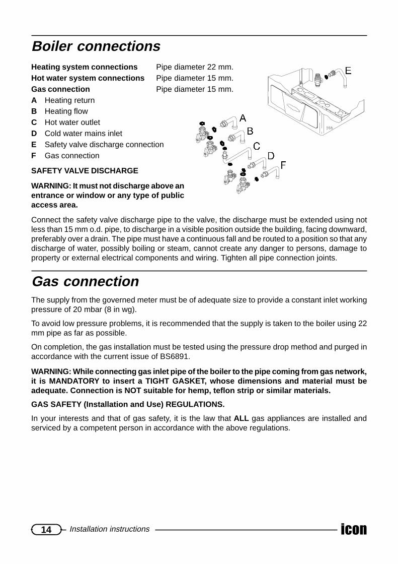
Boiler connectionsHeating system connections Pipe diameter 22 mm.Hot water system connections Pipe diameter 15 mm.Gas connection Pipe diameter 15 mm.A Heating returnB Heating flowC Hot water outletD Cold water mains inletE Safety valve discharge connectionF Gas connection
SAFETY VALVE DISCHARGE
WARNING: It must not discharge above anentrance or window or any type of publicaccess area.
Connect the safety valve discharge pipe to the valve, the discharge must be extended using notless than 15 mm o.d. pipe, to discharge in a visible position outside the building, facing downward,preferably over a drain. The pipe must have a continuous fall and be routed to a position so that anydischarge of water, possibly boiling or steam, cannot create any danger to persons, damage toproperty or external electrical components and wiring. Tighten all pipe connection joints.
Gas connectionThe supply from the governed meter must be of adequate size to provide a constant inlet workingpressure of 20 mbar (8 in wg).
To avoid low pressure problems, it is recommended that the supply is taken to the boiler using 22mm pipe as far as possible.
On completion, the gas installation must be tested using the pressure drop method and purged inaccordance with the current issue of BS6891.
WARNING: While connecting gas inlet pipe of the boiler to the pipe coming from gas network,it is MANDATORY to insert a TIGHT GASKET, whose dimensions and material must beadequate. Connection is NOT suitable for hemp, teflon strip or similar materials.
GAS SAFETY (Installation and Use) REGULATIONS.
In your interests and that of gas safety, it is the law that ALL gas appliances are installed andserviced by a competent person in accordance with the above regulations.

15icon Installation instructions
STATUTORY REQUIREMENTS
The installation of this boiler must be carried out by a competent person in accordance with therelevant requirements of the current issue of:
— The Gas Safety (Installation and Use) Regulations
— The Building Regulations
— The local water company Bylaws
— The Building Standards Regulations (Scotland)
— The Health and Safety at Work Act
SHEET METAL PARTS
WARNING: When installing or servicing this boiler, care should be taken when handling theedges of sheet metal parts to avoid the possibility of personal injury.
INSTALLING THE BOILER
Prior to starting work, the system must be thoroughly flushed to eliminate any foreign bodies andcontaminents such as filings, solder, particles, oil, grease etc.
Note: Solvent products could cause damage to the system.
Boiler installationTo install the boiler, proceed as follows:
— Allowing sufficient clearances for servicing/repair,place the template on the wall (see diagram be-low).
— Determine the position of the flue hole and drillhole for flue, preferably using a 120 mm core drill.
— Drill two 8mm holes for the wallplugs (supplied).
— Screw fixing screws (supplied) into wallplugs, leaveproud by approx. 10 mm.
Note: Boiler fixing holes are keyhole type slots to al-low easy hanging of boiler.
— Remove template.
— Hang the boiler on the screws and tighten screws.
— Connect system pipework and gas connection.
Note:
1. The template is only used as a guide, it can beremoved prior to fitting the boiler.
2. Remove the plastic caps from the boiler connec-tions prior to connecting boiler to the pipework.
PP�����
PP������,FRQ����W�PP������,FRQ����W�
PP����
PP�������PP��������,FRQ����W�PP��������,FRQ����W�
��
PP������,FRQ����W�PP������,FRQ����W�
PP����
),;,1*�+2/(6���PP
�� �� �� �� �������,FRQ����W��������,FRQ����W�
����
BOILER TEMPLATE

16 iconInstallation instructions
$
2
%3
'(
)
,
45
01
+
Horizontal flue installationA GasketB 90° bendD ‘O’ ringE CollarF ClampH ScrewsI Air inlet pipeM External sealing collarN TerminalO ScrewsP Inner elbowQ Inner pipeR Clip
— Fit gasket (A) onto underside of flue elbow (B).
— Fit elbow onto top of boiler ensuring it locates correctly onto fan outlet.
— Carefully insert ‘O’ ring (D) into inner elbow (P).
— Fit external sealing collar (M) onto air inlet pipe (I).
— Fit flue through hole in wall and pull up so that external collar (M) is flush against outside wall.
— Fit collar (E) and clamp (F) to flue and assemble into elbow (B) making sure that both inner andouter pipes are sealed properly.
NOTE: Maximum horizontal length with no additional bends is 3m.
— Tighten up clamp using screws and nuts provided (H & G).
Note: Should it be necessary to cut the flue, always cut equal amounts from both inner and outerpipes. Always cut the end furthest from the terminal.
For each 90 o flue bend fitted, reduce overall flue length by 1 m.For each 45 o flue bend fitted, reduce overall flue length by 1/2 m.
Flue accessory Cat No.C Flue extension kit 885117D 90o bend kit 885118E 45o bend kit 885119

17icon Installation instructions
/
(
'
0
$
%
Vertical flue installationA GasketB Vertical adaptorD ‘O’ ringE CollarL TerminalM Screws
— Fit gasket (A) onto underside of vertical adaptor (B).
— Fit vertical adaptor onto top of boiler ensuring it locates correctly onto fanoutlet.
— Carefully insert ‘O’ ring (D) into vertical adaptor inner spigot.
— For flat roof installation , fit flat roof flashing collar (part no. 885121)
— Fit flue terminal (L) onto roof ensuring flashing makes a watertight joint.
— For pitch roof installation , fit pitch roof flashing collar (part no. 885120)
— Fit flue terminal (L) onto roof ensuring flashing makes a watertight joint.
— Fit collar (E) to vertical flue pipes and assemble between terminal (L)and vertical adaptor (B) making sure that both inner and outer pipesare sealed properly.
NOTE: Maximum vertical height with no bends is 4m.
— Tighten up clamp using screws provided (H).
Note: Should it be necessary to cut the flue, always cut equal amountsfrom both inner and outer pipes.
For each 90 o flue bend fitted, reduce overall flue height by 1 m.For each 45 o flue bend fitted, reduce overall flue height by 1/2 m.
Vertical flue kit 885116Flue accessory Cat. No.
A Pitched roof flashing 885120B Flat roof flashing 885121C Flue extension kit 885117D 90o bend kit 885118E 45o bend kit 885119

18 iconInstallation instructions
Flue configurationATTENTION
If coaxial system would have a total length lower than 2 lin-ear meters (n°1 additional bend = 0.5 linear meters), it willbe necessary to install the diaphragm supplied with thegas boiler, as indicated in the figure besides
'LDSKUDJP

19icon Installation instructions
Electrical connectionIt is important that the mains supply is wired with correct polarity: brown to LIVE, blue toNEUTRAL.
Warning : This boiler must be earthed.
All system components must be of an approved type.
Connection of the whole electrical system and any heating system controls to the electrical supplymust be through a common isolator.
Isolation should preferably be by a double pole switched fuse spur box having a minimum contactseparation of 3 mm on each pole. The fused spur box should be readily accessible and preferablyadjacent to the boiler. It should be identified as to its use.
A fused three pin plug and shuttered socket outlet may be used instead of the fused spur box,provided that:
a) They are not used in a room containing a bath or shower.
b) Both the plug and socket comply with the current issue of BS1363.
The mains electrical supply must be maintained at all times in order to provide domestic hot water.
DO NOT INTERRUPT THE MAINS SUPPLY TO THE BOILER WITH A TIME SWITCH OR PRO-GRAMMER.
The icon 23 t and icon 28 t are delivered with an integral mains supply lead AND an integralexternal controls lead.
EXTERNAL CONTROLS
The boiler will work for heating ASDELIVERED without a room ther-mostat fitted provided the two wireson the integral external controlslead REMAIN LINKED TO-GETHER (as supplied).
If a room thermostat is required, itmust be connected to the externalcontrols lead as shown below, us-ing a suitable electrical connection.
ANY ROOM THERMOSTAT MUSTBE OF THE VOLTAGE FREE TYPE.
Note: For further information, see The Building Regulations 1991 – Conservation of fuel and power –1995 edition – Appendix G, table 4b.
ON NO ACCOUNT MUST ANY ELECTRICAL VOLTAGE BE APPLIED TO EITHER OF THETERMINALS OF THE WHITE EXTERNAL CONTROLS LEAD
WARNING: This boiler must be wired in accordance with these instructions. Any fault aris-ing from incorrect wiring may invalidate the terms of the guarantee.
BOILER
BLACK MAINS LEAD WHITE EXTERNAL CONTROL LEAD
FUSED MAINSSPUR OR
FUSED 3 PINPLUG
VOLTAGE FREEROOM THERMOSTAT
617
icon 23 t
�
icon 28 t

20 iconInstallation instructions
CommissioningThe commissioning and first firing of the boiler must only be carried outby a competent person.
ACCESS FOR ADJUSTMENT
1. Remove the lower grille, remove two screws securing outer casing. Re-move casing by lifting up and forwards.
2. Unscrew 6 screws securing inner casing and remove casing.
3. After commissioning, replace all items in reverse order to removal.
GAS INSTALLATION
It is recommended that any air is purged from the supply at the gas inlet testpoint on the gas valve, see diagram below.
FILLING THE SYSTEM
— Open isolating valves (see “Boiler connections”, items A,B and D) and cap on automatic air vent inside sealed cham-ber.
— Fill system by opening system filling loop until a pressureof between 1 and 2 bar is shown on the boiler pressuregauge.
— Bleed each radiator until a continuous jet of water is ob-tained.
— Do not close automatic air vent cap.
— Open various hot water taps to bleed system.
— Make sure that pressure gauge reads between 1 and 2bar. Re-pressure as necessary.
Important: When venting air from boiler, do not touch theschrader valve on the expansion vessel, it is NOT a vent.
STARTING THE BOILER
Before starting the boiler check that:
— The gas meter tap is open.
— The boiler gas service cock is open.
— The water isolating cocks are open.
— The boiler is connected to the electrical supply.
1 Outlet test point2 Inlet test point3 Vent
�
�
�

21icon Installation instructions
FIRST STARTING UP
— Set boiler to run in central heating as described in ‘Users Instructions’.
— Set heating temperature control to maximum temperature and check that any external con-trols, if fitted, are calling for heat.
— Allow the temperature to rise to the maximum value, with all radiator valves open. The tem-perature rise will cause release of the gases contained in the water of central heating system.
• Gases driven towards the boiler will be automatically released through the automatic airvent.
• The gases trapped at the highest point of the system must be released by bleeding theradiators.
— On reaching maximum temperature, the boiler should be turned off and the system drainedas rapidly as possible whilst still hot.
— Refill system to a pressure of 1 bar and vent as before.
— Restart boiler and operate until a maximum temperature is reached. Shut down boiler and ventheating system. If necessary, top up heating system and make sure that a pressure of 1 bar isindicated on the pressure gauge when system is COLD.
GAS PRESSURES
— Shut down boiler.
— Undo screw on gas inlet test point ‘2’ on gas valve.
— Connect a suitable pressure gauge.
— Start boiler as described in “Users Instructions”.
— Check that there is a constant pressure of 20 mbar. If the pressure is insufficient, it is neces-sary to check the gas supply/pipework and correct any fault.
— Shut down boiler.
— Remove pressure gauge, tighten up test point screw and check for gas soundness.
ACCESS FOR ADJUSTMENT
1. Remove the lower grille, remove two screws se-curing outer casing. Remove casing by lifting upand forwards.
2. Unscrew 6 screws securing inner casing and re-move casing.
3. Loosen, but do not remove, the two knurled nutssecuring controls housing to boiler (behind controlpanel).
4. Lift controls housing from bracket and remove rearcover.
5. After commissioning, replace all items in reverseorder to removal.

22 iconInstallation instructions
SETTING THE CENTRAL HEATING OUTPUT
The central heating output must be set in accordance with the system requirements. To adjust theburner pressure, proceed as follows, referring to the tables listed in ‘Technical Data’:
— Gain access to the PCB, see diagram above.
— Set the “summer/winter” switch to the “winter” position
— Light the burner and check the gas pressure
— Adjust the pressure using potentiometer P1 on the PCB.
— Refit cover to controls housing.
DOMESTIC HOT WATER FLOW ADJUSTMENT
The domestic hot water flow rate is factory set. However, after installation, it may be necessary toadjust the domestic hot water flow rate, proceed as follows:
— Fully open a domestic hot water tap.
— Using a suitable water flow gauge, adjust water flow by turning the adjuster screw on the watervalve (item G, page 27)
— Nominal water flow rate is 9.6 l/min.
Safety devicesOVERHEAT SAFETY
In the event of problem, the overheat safety device causes safety shutdown of the boiler. In theevent of this, the lockout warning light will illuminate. To clear this, turn the summer/winter switchfully to the right or left as appropriate. This resets the boiler.
PCB CONTROLS HOUSING

23icon Installation instructions
Gas valve settingAll boilers are tested and factory set during manufacture. Should it be necessary to reset a gasvalve, for example after replacement, proceed as follows:
MAX/MIN. DOMESTIC HOT WATER OUTPUT ADJUSTMENT
Check that the Inlet pressure is correct for the type of gas being used.
— Set “Summer/Winter” switch to “Summer” position.
— Open the domestic hot water tap fully, wait for 10 seconds and check gas burner pressure ontest point ‘1’, refer to “Technical data”
To adjust the settings, proceed as follows:
— Verify that the modulation coil is energised
— Remove protection cap (C).
— Set maximum pressure by turning knob (B) with 10 mm span-ner. Clockwise to increase, anti-clockwise to decrease.
— Remove electrical connector on modulation coil.
— Keeping knob (B) locked, adjust minimum pressure unscrew-ing screw (A) very slowly, using a 4 mm spanner
— Refit electrical connector and check settings.
— Lock the adjustement device after any setting operation.
AdjustmentsSLOW OPENING REGULATION
Should ignition of the burner be noisy, it will be necessary to adjust the slow opening setting of thegas valve. This adjustment is made on the PCB.
To adjust the slow opening, proceed as follows:
— Switch off the boiler and isolate from the mains supply.
— Remove control housing cover as described previously.
— Remove jumper S1
— Connect a suitable pressure gauge to the gas valve outlet test point ‘I’
— Switch on the boiler and open an hot water tap, the burner will ignite. The gas pressures shouldbe as follows:
• NATURAL GAS= 3 mbar (30 mm w.g.)
— Turn potentiometer P3 (clockwise to increase pressure and counterclockwise to decreasepressure) until the required value is obtained.
— Refit jumper S1.
&
$
%

24 iconInstallation instructions

25icon Installation instructions
1 Air pressure switch2 Overheat thermostat3 Expansion vessel4 Ignition and flame sense electrodes5 Domestic heat exchanger6 Gas valve7 Water valve8 Hydraulic 3-way valve9 N/A10 Drain valve
11 N/A12 Thermistor13 Burner14 Primary heat exchanger15 Automatic air vent16 Fan17 Sealed chamber18 Pump19 Loss of water pressure switch
Boiler schematic

26 iconServicing instructions
Servicinginstructions

27icon Servicing instructions
To ensure the continued efficient and safe operation of the boiler, it is recommended that it ischecked and serviced at regular intervals. The frequency of servicing will depend upon the instal-lation conditions and usage but, in general, once a year should be enough.
It is the law that any servicing is carried out by a competent person.
Routine cleaning and inspection— Operate boiler and check for any faults that need to be put right.
— Isolate boiler from the gas and electrical supplies.
— On completion check all gas carrying parts for soundness with leak detection fluid.
— Remove boiler casing as follows:
OUTER CASING
Remove the lower grille, remove two screws securing outer casing. Remove casing by lifting upand forwards.
COMBUSTION CHAMBER
— Unscrew and remove 6 screws securing sealed chamber cover to boiler. Pull cover forwardand off boiler.
BURNER
— Undo main gas supply nut from burner.
— Pull main burner forward, pull off the ignition and flamesense leads from the electrodes and remove burnerfrom boiler.
Note: The washer between main burner and main burnergas supply must be kept for use on reassembly.
— Remove ignition and flame sense electrodes fromburner.
— Unscrew and remove four injector bar retaining screws and separate injector bar from burner.
— Examine and clean injectors as necessary.
Note: DO NOT use a wire or sharp instrument on the holes.
HEAT EXCHANGER
— Locate the heat exchanger inside the sealed chamber.
— Gain acces to heat exchanger by removing fan and flue hood.
— Examine heat exchanger for any blockages or build up of deposits.
— Clean heat exchanger with soft brush or vacuum cleaner.
REASSEMBLY OF PARTS REMOVED FOR SERVICING
All parts are replaced in reverse order to removal.
28 iconServicing instructions
FLUE SYSTEM
— Check externally to make sure that flue is not blocked
— Inspect flue system to make sure that all fittings are secure.
OPERATION OF FAN
— Switch on electrical supply and turn on gas.
— Set selector switch to “Winter” position.
— Light burner by operating external controls (if fitted) to call for heat.
— Do not light the boiler without the sealed chamber cover fitted
— Check that fan operates when burner light and stops when it goes out.
Replacement of partsTO REPLACE FAN
— Slide flue sensing probe insulating boot away from fan.
— Pull off both red and white sensing probe tubes.
— Disconnect power supply and earth leads to fan.
— Slacken, but do not remove, two screws securing fan to rear of flue hood.
— Supporting fan, unscrew and remove two screws securing fan to front of flue hood.
— Lower fan from top of boiler then tilt base of fan to right hand side. Gently ease fan forwardsand out of boiler.
— Transfer flue sensing probe assembly onto replacement fan.
— Fit replacement fan in reverse order to removal.
Note: Ensure white air sensing tube is connected to upper probe and red tube to lower probe.
TO REPLACE AIR PRESSURE SWITCH
— Locate air pressure switch in upper right hand corner of sealed chamber.
— Pull off plastic tubes from base of switch.
— Remove electrical connections from switch.
— Unscrew and remove two screws securing switch to upper panel and remove switch.
— Fit electrical connections to replacement switch as follows:NO - REDNC - BLACKC - BLUE
— Fit replacement switch in reverse order to removal.
Important: Refit red tube to right hand connector and white tube to left hand connector.

29icon Servicing instructions
TO REPLACE PUMP
— Drain down heating circuit only of boiler as follows:
— From below boiler, close isolating valves on flow and return connections to boiler.
— Open boiler drain valve to right of pump.
Note: It is not necessary to drain down entireheating circuit to carry out this work.
— Unscrew, but do not remove, knurled nutsat rear of controls housing and lift housingoff bracket and clear of pump.
— Pull off electrical connection to pump.
— Supporting pump, unscrew pump connec-tion nuts at top and rear of pump. Removepump by lifting forward and out of boiler.
— Fit replacement pump in reverse order toremoval.
— Open isolating valves on flow and return connections,
— Refill, vent and pressurise boiler. Check for leaks.
TO REPLACE GAS VALVE
— Isolate boiler from gas supply.
— Remove controls housing as described in ‘To re-place pump”.
— Remove clear plastic sensing pipe from gas valve.
— Unscrew and remove upper screw holding gasvalve ignition box onto gas valve body.
— Carefully pull off ignition box, leaving electrical wir-ing connected, and move clear of gas valve.
— Remove electrical connections to gas valve modu-lating coil.
— Disconnect gas inlet cock from boiler.
— Undo nuts on gas valve to burner supply pipe andswing pipe clear of gas valve.
— Unscrew and remove two screws securing gas valve to boiler lower frame.
— Fit replacement gas valve in reverse order to removal.
Note: When refitting electrical connections to gas valve modulating coil, the polarity is not impor-tant.

30 iconServicing instructions
TO REPLACE DOMESTIC HEAT EXCHANGER
— Drain down heating circuit of boiler as described previously.
— Drain down hot water circuit of boiler as follows:
— From below boiler, close cold water inletisolating valve.
— Open a hot tap to drain hot water circuit.
— Remove clip (A) and pull off microswitchassembly
— Undo connections (B), (C), (D) and (F) on3 way valve
— Grasp 3 way valve and lift upwards releas-ing ‘O’ ring joint (E)
— Remove 3 way valve and domestic heatexchanger assembly from boiler.
Important: Take care not to drip water intopub housing when removing assembly.
— Fit replacement heat exchanger in reverseorder to removal.
— Open isolating valves on flow and return connections, refill, vent and pressurise boiler. Checkfor leaks.
— Open cold water isolating valve. Check for leaks.
TO REPLACE THERMISTOR
— Locate thermistor clipped onto flow pipe behind pump.
— Pull off clip from flow pipe.
— Remove electrical connections from thermistor.
— Fit replacement thermistor in reverse order to removal.
Note: 1) No heat sink compound is required.
2) The polarity of the connections is not important.
TO REPLACE OVERHEAT THERMOSTAT
— Locate overheat thermostat on left hand side of main heat exchanger at rear.
— Remove electrical connections from overheat thermostat.
— Unscrew and remove two screws securing overheat thermostat to heat exchanger.
— Fit replacement overheat thermostat in reverse order to removal.
Note: 1) No heat sink compound is required.
2) The polarity of the connections is not important.
A
F
BC
E G D

31icon Servicing instructions
Schematic wiring diagram
IG Mains switchC PumpE/I Summer/winter selectorPSA Loss of water pressure switchMOD Modulating coilS ThermistorMP Water valve microswitchCA Ignition and flame control unitEA Ignition electrodes
ER Flame sense electrodeLN Mains lampTS Overheat thermostatR Lockout reset switchLB Lockout warning lightMV FanMPV Air pressure switchMO TimeclockCO Timeclock microswitch
Coloursabbreviations:BK Black
BN Brown
BU Blue
GN Green
GNYE Green-Yellow
GY Grey
OG Orange
RD Red
VT Violet
WH White

02/2000 COD. 982160005 / REV. 06
SUPPORTED BY