Embed Size (px)
Citation preview
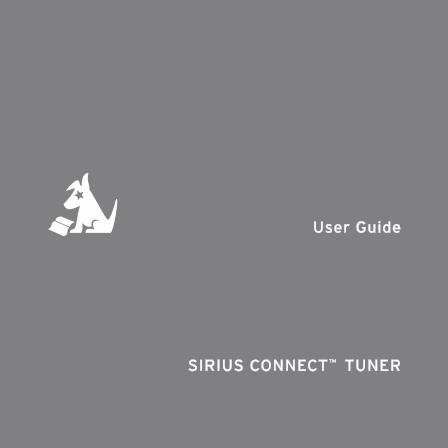
User Guide
SiriUS ConneCt™ tUner

Congratulations on your purchase of the SIRIUS Connect SCH1P2 Satellite Radio Tuner!
Your new SCH1P2 SIRIUS Connect Satellite Radio Tuner is designed to work with SIRIUS-Ready receivers. Check the SIRIUS website for model compatibility.
For the latest information about this and other SIRIUS products and accessories, visit http://www.sirius.com.
[ Table of Contents ] �
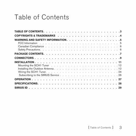
Table of Contents
Table of ConTenTS 3
CoPyRIgHTS & TRademaRkS 4
WaRnIng and SafeTy InfoRmaTIon 5FCC Information . . . . . . . . . . . . . . . . . . . . . . . . . . . . 5Canadian Compliance . . . . . . . . . . . . . . . . . . . . . . . . . . 6Safety Precautions . . . . . . . . . . . . . . . . . . . . . . . . . . . . 6
PaCkage ConTenTS 7
ConneCToRS 9
InSTallaTIon 11Mounting the SCH1 Tuner . . . . . . . . . . . . . . . . . . . . . . . . 12Installing the Outdoor Antenna . . . . . . . . . . . . . . . . . . . . . . . 12Wiring the SCH1 Tuner . . . . . . . . . . . . . . . . . . . . . . . . . . 24 Subscribing to the SIRIUS Service . . . . . . . . . . . . . . . . . . . . . 26
oPeRaTIon 27
SPeCIfICaTIonS 28
SIRIUS Id 29

[ Copyrights & Trademarks ]�
Copyrights & Trademarks
© 2008 Sirius Satellite Radio Inc. All Rights Reserved.
® “SIRIUS”, the SIRIUS dog logo, channel names and logos are trademarks of Sirius Satellite Radio Inc. All Rights Reserved.
™ “SiriusConnect” is a trademark of Sirius Satellite Radio Inc.
Hardware, subscription, and activation fee required. For full Terms & Conditions, visit http://sirius.com. Prices and programming are subject to change. Not available in HI and AK. Equipment and subscription sold separately. Installation required with some equipment.

[ Warning and Safety Information ] �
Warning and Safety Information
FCC Information
This device complies with part 15 of the FCC Rules. Operation is subject to the fol-lowing two conditions:
1. This device may not cause harmful interference, and2. This device must accept any interference received, including interference that
may cause undesired operation.
Note: This equipment has been tested and found to comply with the limits for a CLASS B digital device, pursuant to Part 15 of the FCC Rules. These limits are designed to provide reasonable protection against harmful interference when the equipment is operated in a commercial environment. This equipment generates, uses, and can radiate radio frequency energy and, if not installed and used in accordance with the instructions, may cause harmful interference to radio communications. However, there is no guarantee that interference will not occur in a particular installation. If this equipment does cause harmful inter-ference to radio or television reception, which can be determined by turning the equipment off and on, the user is encouraged to try to correct the interference by one or more of the following measures:
1. Reorient or relocate the receiving antenna.2. Increase the separation between the equipment and the receiver.3. Connect the equipment into an outlet on a circuit different from that to
which the receiver is connected.4. Consult the dealer or an experienced radio/TV technician for help.
WaRnIng
Changes or modifications not expressly approved by the manufacturer could void the user’s authority to operate the equipment.

[ Warning and Safety Information ]�
Canadian ComplianceThis Class B digital apparatus complies with Canadian ICES-003.
Cet appareil numérique de la classe B est conforme à la norme NMB-003 du Canada.
Safety PrecautionsBe sure to observe the following warnings. Failure to follow these safety instructions and warnings may result in a serious accident and/or personal injury.
Install the cables and wiring so that it is not crimped or pinched by screws or sharp metal edges. Route the cables away from moving parts or sharp pointed edges. This will prevent crimping and damage to the wiring. If the wiring must pass through a metal hole, be sure to use a rubber grommet to prevent the wire’s insula-tion from being cut by the metal edge of the hole.Do not open, disassemble or alter the unit in any way. Doing so may result in fire, electric shock or product damage.Do not insert any objects into the unit. Doing so may result in fire, electric shock or product damage.Do not install the unit to high levels of humidity, moisture or dust. Doing so can result in electric shock or product failure.
•
•
•
•

[ Package Contents ] �
Package Contents
The following items are included with your purchase of the SCH1P2. Unpack the kit carefully and make sure that everything shown is present. If anything is missing or damaged, or if the kit fails to operate properly, notify your dealer immediately. It is rec-ommended that you retain the original carton and packing materials in case you need to ship your kit in the future.
SCH1 SIRIUS Connect TunerSCH1 SIRIUS Connect Tuner RS232 adapter CableRS232 adapter Cable
dIn CabledIn Cable Rg-174 adapter CableRg-174 adapter Cable aC Power adapteraC Power adapter

[ Package Contents ]�
outdoor antenna and antenna Installation Itemsoutdoor antenna and antenna Installation Items

[ Connectors ] �
Connectors
Figure 1 and the table following identify and describe the connectors of the SCH1 Tuner.
AUDIOOUT 8 PIN OPTICALR L
DC 5V ANT
AudioConnectors
L/R
OpticalAudio
Connector
DINConnector
AC AdapterConnector
Indoor/OutdoorAntenna
Connector
description of the SCH1 Connectors
Connector description
Audio Connector L/RL/R audio connection for RCA-type audio cables. (Optional, cable not provided.) (Used when audio is not provided via the DIN cable.)
figure 1figure 1

[ Connectors ]10
description of the SCH1 Connectors
Connector description
DIN ConnectorConnection for the DIN cable to the SIRIUS-Ready receiver.
Optical Audio ConnectorAudio connection when using an optical cable. (Op-tional, cable not provided.) (Used when audio is not provided via the DIN cable.)
AC Adapter Connector
Connection for the AC Power Adapter. Note that the AC Power Adapter is used only when your SIRIUS-Ready receiver does not supply power to the tuner via the DIN cable connection.
Indoor/Outdoor Antenna Connector
Connector for the Indoor/Outdoor Antenna.

[ Installation ] 11
Installation
It is recommended that prior to starting the installation, you read this installation sec-tion completely and follow the instructions. In addition, consult the manual of the audio device to which you will be connecting the SCH1 Tuner to determine the required installation configuration.
The SCH1 Tuner can be connected to a SIRIUS-Ready receiver using the DIN cable, or by using the provided RS-232 Adapter Cable.
When connecting using a DIN cable:
If power for the SCH1 Tuner is not provided by your audio device via the DIN cable connection, you will need to use the provided AC Power Adapter to provide power for the SCH1 Tuner.
If audio input from the SCH1 Tuner is not supported via the DIN cable connection of your audio device, you will need to connect the audio output of the SCH1 Tuner to your audio system via the RCA-type or Optical audio output connectors of the tuner. (You will need to purchase the appropriate cable separately.)
When connecting using the RS-232 Adapter Cable:
The AC Power Adapter must be connected to the power connector on the RS-232 Adapter Cable.
note: do not connect the aC Power adapter to the SCH1 Tuner when us-ing the RS-232 adapter Cable
The maximum length of RG-6 cable between the Outdoor Antenna and the SCH1 Tuner is 50 ft. For longer lengths the Splitter/Amplifier must be used. When the Split-ter/Amplifier is used, the maximum lengths of RG-6 cable are 100 ft. from the Outdoor Antenna to the Splitter/Amplifier, and 50 ft. from the Splitter/Amplifier to the SCH1 Tuner. (Refer to Figures 15 & 16.) RG-6 cable(s) are not provided.
•
•
•
•

[ Installation ]12
Mounting the SCH1 Tuner
Consider the mounting location carefully to be sure that you avoid the following:
Any location where the tuner is exposed to moisture.Any location where the tuner is exposed to extreme heat.
The tuner may be mounted on a wall with #10 screws, using the slots on the under-side of the tuner to hang on the tuner on the screws. (Figure 2) Alternately, the tuner may placed on any flat surface.
SCREWMOUNTING SLOTS
Installing the Outdoor Antenna
Before installing the indoor/outdoor antenna, read this entire section. To ensure con-sistent reception of the SIRIUS signal it is important that the antenna be installed and oriented according to these installation instructions.
determining a location for the antenna
For correct operation and best reception of the SIRIUS signal, it is important that the
••
figure 2figure 2

[ Installation ] 1�
outdoor antenna is located in a place where it will have a clear view of the SIRIUS satellites in the sky. Obstructions such as bushes, trees, other homes or buildings, overhangs, soffits, chimneys, gables, dormers, etc., will impair or prevent the antenna from receiving a signal.
The best reception is obtained if the pod portion of the antenna (where the SIRIUS logo is printed) has a clear 360 degree view of the sky within the cone-shaped area shown in Figure 3.
No obstructions to thesky within this area
If you cannot obtain a clear 360 degree view of the sky, then you must at least have a clear view of the sky in the direction of the SIRIUS satellites, as shown in the following map diagram.
figure 3figure 3

[ Installation ]1�
1
2 3
45
HORIZON
SKY
SOUTH
WEST EAST
NORTH
Use the above map and find the area you are located in (1 to 5). Then find the direc-tion in which you need to have a clear view of the sky:
area 1: You will need a location with a clear view of the sky facing eaST or noRTHeaST or SoUTHeaST
area 2: You will need a location with a clear view of the sky facing noRTH or noRTHeaST
area 3: You will need a location with a clear view of the sky facing noRTH or noRTHWeST
area 4: You will need a location with a clear view of the sky facing WeST or noRTHWeST or SoUTHWeST
area 5: You will need a clear view of the sky facing STRaIgHT UP
figure 4figure 4

[ Installation ] 1�
Choose a mounting location for the antenna which has an unobstructed view of the sky in the direction for your area.
For example, suppose you live in area 2. You determined that your antenna will need to have a clear view of the sky facing north or northeast. The exact direction is determined by your specific location in area 2 relative to the X on the map: If you live in Texas, you will need a more north facing clear view of the sky whereas if you live in southern California, you will need a more northeast facing clear view of the sky.
Figure 5 shows a correct antenna installation for area 2, with a clear view of the sky in the north to northeast direction.
No obstructions to thesky within the area facing
North to Northeast
N
W E
S
NORTHfigure 5figure 5

[ Installation ]1�
antenna mounting options
There are three possible mounting options for the outdoor antenna, and the antenna mounting location you have chosen may determine which mounting methods you can use:
Wall mount: Mounting the antenna directly on the side of a home or building.
Roof mount: Mounting the antenna on the roof of a home or building.
mast mount: Mounting the antenna on a mast or pole, such as an existing satellite TV dish mast, an existing TV antenna mast, or other mast or pole, not exceeding 2 inches in diameter.
Wall Mount
The antenna mounting bracket should be oriented in a vertical position (Figure 6) and mounted directly to the wall of the building or home using the provided #10 screws.
MOUNTINGHOLES
Remember to avoid blocking the antenna’s view of the sky as described in the previ-ous section by locating the antenna too high under the eaves or soffit of the home or building. Refer to Figure 7.
•
•
•
figure 6figure 6

[ Installation ] 1�
UNOBSTRUCTEDVIEW OF THE SKY
INCORRECT CORRECT
UNOBSTRUCTEDVIEW OF THE SKY
CORRECT
OBSTRUCTED
Once you have determined a suitable mounting location, use the mounting bracket as a template and mark the wall with the location of the four screw holes in the bracket. Then, using a 3/32 in. drill bit, drill pilot holes in the wall for the screws and then screw the bracket to the wall.
Roof Mount
When mounting the antenna on the roof of a home or building, mount the antenna as close as possible to the peak of the roof. It can be mounted on the chimney or on the soffit of the home or building. Do not mount it directly on the roof surface to avoid leaks. Remember to avoid blocking the antenna’s view of the sky by locating it where a chimney, dormer, gable, etc., may obstruct the view of the sky.
figure 7figure 7

[ Installation ]1�
MOUNTINGHOLES
The antenna mounting bracket should be oriented in a vertical position as shown in Figures 8 and 9, and mounted directly to the building or home using the provided #10 screws.
Once you have determined a suitable mounting location, use the mounting bracket as a template and mark the mounting surface with the location of the four screw holes in the mounting bracket. Then, using a 3/32 in. drill bit, drill pilot holes for the screws. It may be necessary to fill the holes with a small amount of roof cement or caulk to insure a watertight installation. Screw the bracket to the mounting surface using the provided #10 screws.
figure 8figure 8
figure 9figure 9

[ Installation ] 1�
Mast Mount
The outdoor antenna can be mounted on most any mast or pole which does not exceed 2 inches in diameter using the provided U-bolts and mounting brackets, as shown in Figure 10. If you have a satellite TV dish, the outdoor antenna may be mounted on the same mast as the satellite dish, but remember that the dish cannot obstruct the antenna’s view of the sky in the direction which you determined from the map in the previous section.
To mount the antenna to the mast, you will need to use the two provided U-bolts, the two mounting brackets, and the four hex nuts. Keep in mind that the antenna cable is routed under the lower U-bolt, in the slot provided in the antenna base as shown in Figure 11.
figure 10figure 10

[ Installation ]20
Slide one of the U-bolts through the holes at the top of the mounting bracket. Then slide one of the mounting brackets over the two legs of the U-bolt as shown in Figure 12.
Next, screw the hex nuts on each leg until they are snug. Do not yet tighten the hex
figure 11figure 11
figure 12figure 12

[ Installation ] 21
nuts beyond finger tight. Repeat this procedure with the other U-bolt. When all the hex nuts are snug, verify that the antenna is facing the correct direction and begin tighten-ing each hex nut with a 3/8” wrench. Turn each hex nut one-half turn and then move to the next hex nut repeating this one-half turn pattern until all the hex nuts are equally tight. Tighten the hex nuts enough so that the antenna is secured to the mast or pole, but do not overtighten them.
adjusting and aiming the antenna
The pod portion of the antenna (where the SIRIUS logo is printed) needs to be adjusted and aimed so that it is level and horizontal to the sky. There are two possible adjustments that may be made on the antenna to accomplish this: tilting the antenna pod itself (1), and adjusting the antenna support arm (2), as shown in Figure 13.
1Antenna Pod
HORIZONTAL LEVEL
SKY
AdjustmentScrew
AdjustmentScrew
2
Slightly loosen the adjustment screws and position the antenna so that the top of the figure 13figure 13

[ Installation ]22
antenna pod is level, with the top of the pod horizontal to the sky as shown. When the antenna is adjusted correctly, tighten the adjustment screws but be careful not to overtighten them.
Take the RG-6 cable and thread one end of the cable through the opening in the end of the rubber boot as shown in Figure 14. Then connect the cable to the antenna pod as shown in the illustration following.
Slide the rubber boot over the cable connection to provide a weather proof seal and install the cable tie around the cable directly below the rubber boot to prevent the rub-ber boot from slipping down. Trim off the excess cable tie.
Connect the RG-6 cable to the RG-174 adapter cable as shown in Figure 15. For RG-6 lengths greater than 50 ft., connect as shown in Figure 16.
Connect the RG-174 Adapter Cable to the SCH1 Tuner ANT connection.
figure 14figure 14

[ Installation ] 2�
RG-174RG-6 Adapter Cable
50’ MAX.
DC
5VANT
RG-174RG-6RG-6
Terminator (orconnect tosecond tuner)
Splitter/Amplifier
Adapter Cable
100’ MAX.50’ MAX.
DC
5VANT
IN
OU
T1O
UT2
Testing and optimizing the antenna Signal StrengthThe stronger the SIRIUS signal strength, the less likely it is that you will experience an interruption of the audio when listening to a broadcast. To assist you in adjusting the antenna aiming for optimal reception, the SIRIUS-Ready receiver can display a screen showing the strength of the SIRIUS signal being received, similar to Figure 17.
To access the antenna aiming or signal indicator screen, consult the user guide which accompanied your SIRIUS-Ready receiver. The SATELLITE portion of the display screen (Figure 17) shows the strength of the signal being received from the satellite, while the TERRESTRIAL portion of the display screen shows the strength of the signal being received from terrestrial based transmitters, if available.
figure 15figure 15
figure 16figure 16

[ Installation ]2�
Antenna Aiming
Press BACK when done
SATELLITE
Adjust your antennaposition to maximize signalstrength.
TERRESTRIAL
Wiring the SCH1 Tuner
The SCH1 Tuner can be wired using the DIN cable connection as shown in Figure 18, or using the RS232 Adapter Cable as shown in Figure 19.
When connecting using a DIN cable:
If power for the SCH1 Tuner is not provided by your audio device via the DIN cable connection, you will need to use the provided AC Power Adapter to provide power for the SCH1 Tuner.
If audio input from the SCH1 Tuner is not supported via the DIN cable connection of your audio device, you will need to connect the audio output of the SCH1 Tuner to your audio system via the RCA-type or Optical audio output connectors of the tuner. (You will need to purchase the appropriate cable separately.)
When connecting using the RS-232 Adapter Cable:
The AC Power Adapter must be connected to the power connector on the RS-232 Adapter Cable.
note: do not connect the aC Power adapter to the SCH1 Tuner when us-ing the RS-232 adapter Cable
Please consult your audio equipment manuals for the wiring connections needed for the SCH1 Tuner to operate with your particular equipment.
•
•
•
•
figure 17figure 17

[ Installation ] 2�
AU
DIO
OU
T8 PIN
OPTICAL
RL
DC
5V
ANT
AUDIO OUTPUT L/R(OPTIONAL, CABLE
NOT INCLUDED)
OPTICAL LINK(OPTIONAL, CABLE
NOT INCLUDED)
DIN CABLETO SIRIUS-READY
RECEIVER
INDICATORLIGHT
AC POWER ADAPTER(OPTIONAL, AC ADAPTER IS
USED ONLY IF POWER IS NOTSUPPLIED VIA DIN CABLE)
OUTDOOR ANTENNA
AU
DIO
OU
T8 PIN
OPTICAL
RL
DC
5V
ANTRS-232
ADAPTERCABLE
OUTDOOR ANTENNA
INDICATORLIGHT
NOTE: DO NOT CONNECT THE AC POWER ADAPTER HERE. CONNECT ONLY TO
THE RS-232 ADAPTER CABLE.
RS232 CABLETO SIRIUS-READY
RECEIVER
AUDIO OUTPUTL/R
AC POWERADAPTER
figure 18figure 18
figure 19figure 19

[ SIRIUS ID ]2�
Subscribing to the SIRIUS Service
Before you can listen to SIRIUS radio, you need to subscribe to the SIRIUS Satellite Radio service. To subscribe do the following:
1. Be sure that the SCH1 is correctly installed according to the previous installation instructions.
2. Refer to the operators guide that accompanied your receiver. Turn the receiver on and select SIRIUS radio.
3. After the startup sequence, the SCH1 will update the SIRIUS channel line-up. Wait until the channel updates have completed before pressing any buttons.
4. Once the channels have been updated, the display will change to Call 1-888-539-SIRIUS to Subscribe and will tune to channel 184. You will not be able to listen to SIRIUS satellite radio until you activate your SIRIUS subscription.
5. You’ll need to ascertain the SCH1’s unique 12-digit SIRIUS ID number (SID). The SID number can be found in several places:
On a label on the SCH1P2 packagingOn the underside of the SCH1The SID can be displayed by tuning to channel 0.
Write down the SID number in the space provided near the end of this manual.
6. Have your credit card handy and contact SIRIUS on the Internet at: https://activate.siriusradio.com/ and follow the prompts to activate your subscription. You can also call SIRIUS toll-free at: 1-888-539-SIRIUS (1-888-539-7474).
7. When you have successfully subscribed to the SIRIUS service, and the SCH1 has been updated with your subscription information, an alert will be displayed indicating that the tuner has been subscribed.
You are now ready to begin enjoying SIRIUS Satellite Radio’s digital radio entertain-ment and traffic service!
•••

[ Operation ] 2�
Operation
Consult the owners manual of your SIRIUS-Ready receiver for operating instructions.
The SCH1 Tuner has an indicator light which provides basic status information about the tuner. When the tuner is first powered on, this light will be red to indicate the tuner is receiving power. After the tuner is initialized by the Sirius-Ready receiver or controller:
Steady Red: Initial power-on indication.
Flashing Red: Indicates that the antenna is not connected to the Tuner.
Steady Amber: Indicates that the antenna is connected to the Tuner, but no signal is being received.
Steady Green: Indicates that the Tuner is functioning properly and receiving a good signal.

[ Specifications ]2�
Specifications
Operational Frequencies
Satellite . . . . . . . . . . . . . . . . . . . . . . . . . . . . . . . . . . . . . . . . .2322.293/2330.207 MHz
Terrestrial . . . . . . . . . . . . . . . . . . . . . . . . . . . . . . . . . . . . . . . . . . . . . . . . . 2326.250MHz
Power Requirements . . . . . . . . . . . . . . . . . . . . . . . . . . . . . . . . . . . . . . . . . . . . 5 Volts DC
Dimensions . . . . . . . . . . . . . . . . . . . . . . . . . . . . . . . . . . . . . . . . .1” x 2.6” x 3.6” (WxHxD)
26mm x 66mm x 92mm (WxHxD)
Antenna Type . . . . . . . . . . . . . . . . . . . . . . . . . . . . . . . . . . . . . . . . . . . . . . . . . . Windowsill
Antenna Cable Length . . . . . . . . . . . . . . . . . . . . . . . . . . . . . . . . .21’ (single micro-cable)
Connector Type . . . . . . . . . . . . . . . . . . . . . . . . . . . . . . . . . . . . . . . . . . . . . . . . . . . . .SMB
Audio Interface . . . . . . . . . . . . . . . . . . . . . . . . . . . . . . RCA-type Stereo L/R Connectors
Optical Link Connector
Audio Output . . . . . . . . . . . . . . . . . . . . . . . . . . . . . . . . . . . . . . . . . . . . . 0.75v, 550 Ohm
Signal to Noise Ratio . . . . . . . . . . . . . . . . . . . . . . . . . . . . . . . . . . . . . . . . . . . . . . . . 80dB
Weight . . . . . . . . . . . . . . . . . . . . . . . . . . . . . . . . . . . . . . . . . . . . . . . . . . . 0.1 kg. (3.5 oz.)
Included Cable . . . . . . . . . . . . . . . . . . . . . . . . . . . . . . . . . . . . . . . . . . . . 8-Pin DIN Cable

[ SIRIUS ID ] 2�
SIRIUS ID
Write down the SIRIUS ID (SID) of your SCH1P2 in the space provided below.
SID: ____________________________________


SCH1P (SCH1P061608a)oo.ABCD1.001
sirius.com
SiriUS Satellite radio inc.1221 Avenue of the Americasnew York, nY 10020
800.869.5590