Embed Size (px)
Citation preview

User Guide
Contents Chapter 1 Software introduction .............................................. 4
1.1 Brief introduction .................................................... 4
1.2 Software structure .................................................... 4
1.3 Application .......................................................... 5
1.3.1 Application on individual computer .............................. 5
1.3.2 Application in the LAN/WAN/Internet ............................. 5
1.4 The functions and advantages......................................... 6
Chapter 2 Software installation & uninstall ..................................... 7
2.1 Software running environment ........................................ 7
2.1.1 System requirement ............................................ 7
2.1.2 Operating system supported .................................... 7
2.2 Software installation .................................................. 7
2.2.1 Windows ....................................................... 7
2.2.2 Linux .......................................................... 9
2.2.3 Mac ............................................................ 9
2.2.4 Other OS ....................................................... 9
2.3 Start software ........................................................ 9
2.3.1 Windows ....................................................... 9
2.3.2 Mac OS ....................................................... 10
2.3.3 Other OS ...................................................... 10
2.4 Software uninstallation .............................................. 10
2.4.1 Windows ...................................................... 10
2.4.2 Mac OS ....................................................... 11
2.4.3 Other OS ...................................................... 12
Chapter 3 Main functions introduction ........................................ 13
3.1 Software management ............................................... 13
3.1.1 Be software administrator and modify password ................. 13
3.1.2 The communication port setting ................................ 13
3.2 Searching Device automatically ...................................... 14
3.3 The monitoring with local agent ...................................... 15
3.3.1 Communication mode .......................................... 15
3.3.1.1 COM port communication ................................. 15
3.3.1.2 USB communication ..................................... 15
3.3.2 Device status view ............................................. 15
3.3.3 Device control parameters setting .............................. 16
3.3.4 UPS shutdown control ......................................... 16
3.3.5 Battery control parameter setting ............................... 19
3.3.6 Battery self-test................................................ 20
3.3.7 UPS log ....................................................... 21
3.3.7.1 Record setting ........................................... 21
3.3.7.2 Data log ................................................. 22
3.3.7.3 Event log ................................................ 22
3.3.8 Load Segment Control setting .................................. 23
3.3.9 UPS model setting ............................................. 23
3.3.10 Battery test to low took less than setting minute ................ 24
3.4 Warning event notification method ................................... 24
3.4.1 Real time warning dialog ....................................... 25
3.4.2 E-mail notification ............................................. 25
3.4.3 SMS notification ............................................... 26
3.5 System shutdown protection ......................................... 27
3.5.1 Local computer shutdown protection............................ 27
3.5.2 Remote computer shutdown protection ......................... 29
3.5.3 Remote Linux/Unix/NAS computer shutdown protection .......... 31
3.5.4 ESXi host and VMs shutdown protection ........................ 33
3.6 Remote monitoring Device ........................................... 35
3.6.1 Install software on different computer to monitor remote device ... 35
3.6.2 Webserver Function ........................................... 38
3.7 SNMP centralized monitoring......................................... 39
3.7.1 Becoming SNMP administrator ................................. 39
3.7.2 Area management ............................................. 40
3.7.3 UPS management .............................................. 40
3.7.4 SNMP event log................................................ 44
3.7.5 SNMP Trap Receiving Port Setting .............................. 45
3.8 Wake on LAN function ............................................... 45
3.9 Preference .......................................................... 46
3.9.1 Temperature unit .............................................. 46
3.9.2 Date format ................................................... 47
3.9.3 Bottom Image ................................................. 47
3.9.4 Advance Settings .............................................. 47
3.10 Language .......................................................... 47
3.11 Start Wizard ....................................................... 47
3.12 Modbus TCP monitoring ............................................ 47
Chapter 4 Frequent questions ............................................... 50
4.1 How to do if software port is in use by other software .............. 50
4.2 Configure the computer powered by Multi-UPS shut down safely ... 51
4.3 The communication between UPS and software on Debian Etch Stable
Core 2.6 18-5-486 ................................................... 55
4.4 The communication between UPS and software on RedHat Core 2.6 956
4.5 Mac OS with terminal interface opened can be shut down normally . 56
4.6 How to use software on Windows server 2008 core ................ 57
4.7 How to use software on VMware ESX 3.5/4.0/4.1 ................... 59
4.8 How to use software on VMware ESXi OS ......................... 64
Chapter 5 Software Secure Usage statement .................................. 65
Appendix A - The detail information about glossary ........................... 66
Appendix B - Event List ..................................................... 67
Chapter 1 Software introduction 1.1 Brief introduction
Software is a UPS monitoring software, that can support to monitor the status of local
UPS and remote UPS in the LAN or WAN. User can monitor and configure the UPS on
any computer in the LAN or WAN.
The software monitors the real-time status of UPS at all times, when status of UPS is
abnormal, software will give warning information to user, protect the key equipment and
shut down the system of the computer when needed.
The software can protect computer systems from being shut down abnormally when
power fails. With the software, a UPS can provide security protection for more than one
computer at the same time, including shutting down system in security, saving application
data and shut down the output of the UPS when power fails.
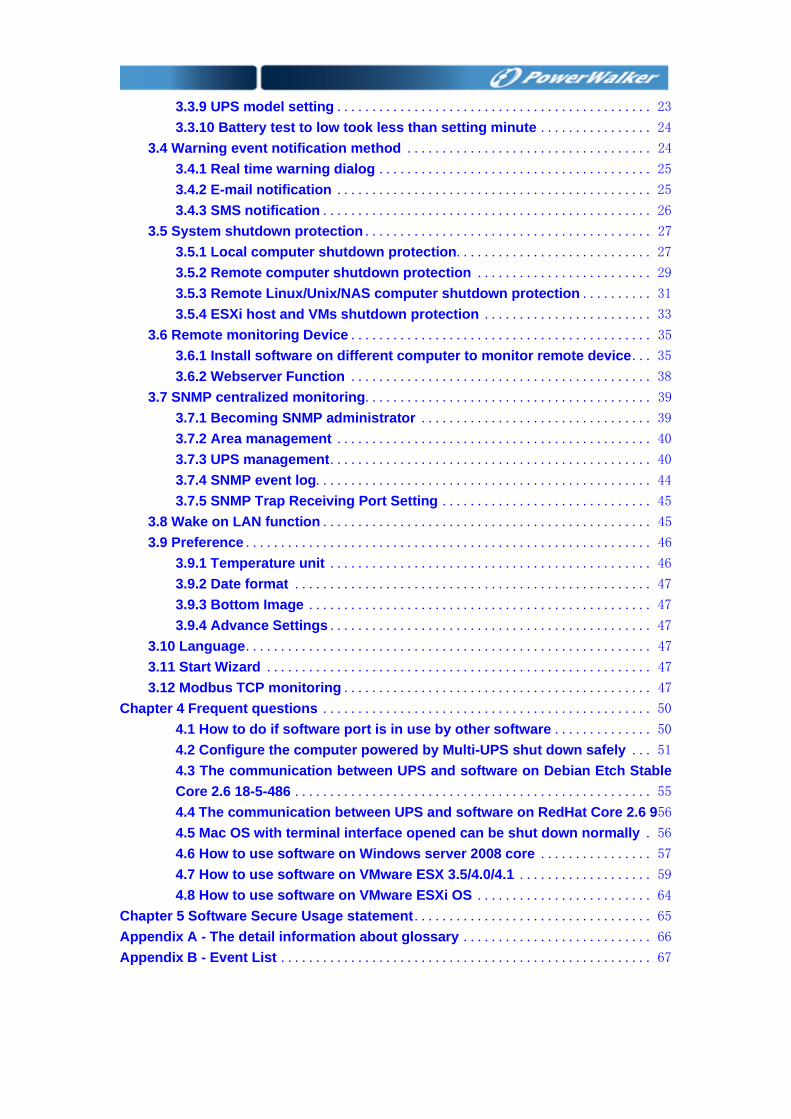
1.2 Software structure There are three components of the software: Agent, Monitor and Tray Icon.
Please refer to the following figure 1.2.1 to comprehend the relationship of the three
components.
Figure 1.2.1
Agent is the key component of the software, running as a system service on
background. Agent communicates with UPS, logs the event of UPS, notifies user when
the UPS is abnormal, takes some actions according to the user configuration and shuts
down the system of computer when necessary. User can configure Agent by Monitor.
Monitor is the user interface of the software. User can get real-time status of UPS,
configure the parameters of UPS and set shutdown parameters by monitor.
Tray Icon, shown on the taskbar of Windows system, is the management tool of the
software. Start software from “start” menu of system or login in system when restart
system after installing software, if the software runs normally, a green icon will be shown
on the taskbar of Windows system.
▲ The Tray Icon exists on Windows only.
There are two different statuses of Tray Icon to display the current status of Agent.
Refer to the following figure 1.2.2.
Agent stop
Agent is running
Figure 1.2.2
1.3 Application
1.3.1 Application on individual computer
Refer to figure1.3.1
Figure 1.3.1
1.3.2 Application in the LAN/WAN/Internet
Refer to figure 1.3.2
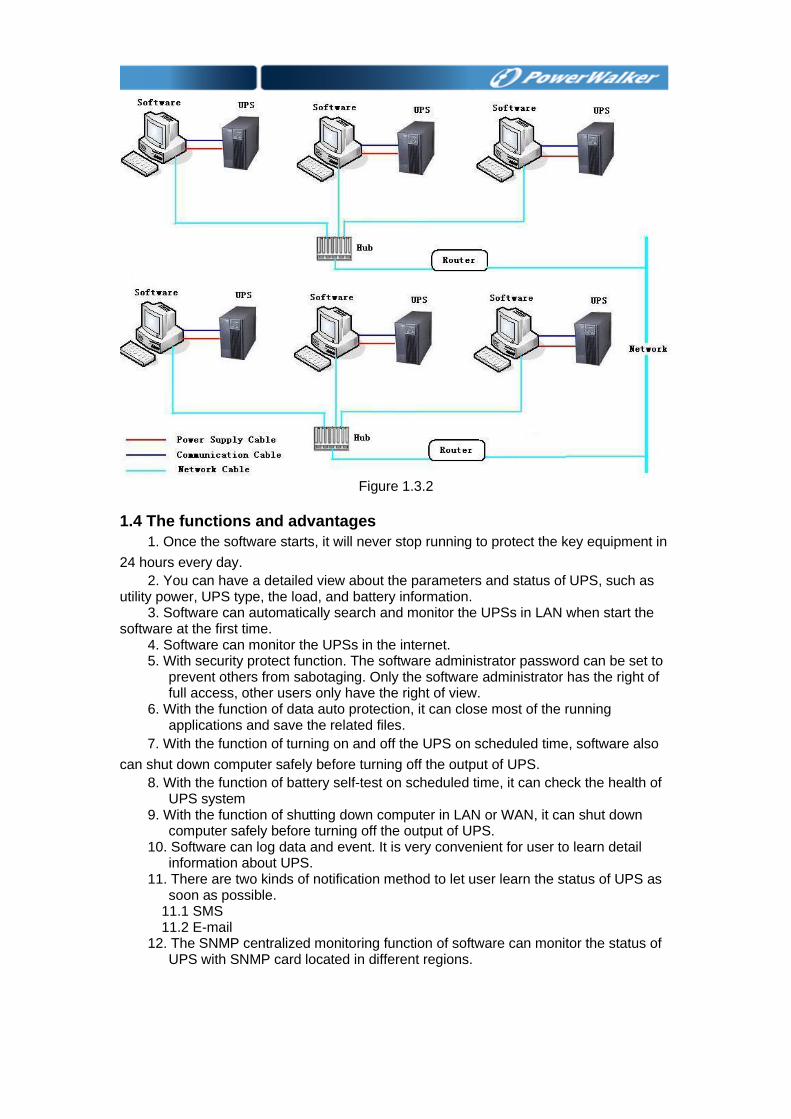
Figure 1.3.2
1.4 The functions and advantages
1. Once the software starts, it will never stop running to protect the key equipment in
24 hours every day.
2. You can have a detailed view about the parameters and status of UPS, such as utility power, UPS type, the load, and battery information.
3. Software can automatically search and monitor the UPSs in LAN when start the software at the first time.
4. Software can monitor the UPSs in the internet. 5. With security protect function. The software administrator password can be set to
prevent others from sabotaging. Only the software administrator has the right of full access, other users only have the right of view.
6. With the function of data auto protection, it can close most of the running applications and save the related files.
7. With the function of turning on and off the UPS on scheduled time, software also
can shut down computer safely before turning off the output of UPS.
8. With the function of battery self-test on scheduled time, it can check the health of UPS system
9. With the function of shutting down computer in LAN or WAN, it can shut down computer safely before turning off the output of UPS.
10. Software can log data and event. It is very convenient for user to learn detail information about UPS.
11. There are two kinds of notification method to let user learn the status of UPS as soon as possible.
11.1 SMS 11.2 E-mail 12. The SNMP centralized monitoring function of software can monitor the status of
UPS with SNMP card located in different regions.
Chapter 2 Software installation & uninstall 2.1 Software running environment
2.1.1 System requirement 1. 256MB hard disk space at least. 2. TCP/IP protocol must be installed to support network management.
3. For local connection, an available communication port (RS-232 Serial Port or USB port) is needed to connect UPS with a communication cable.
Note: the OS should support JDK 1.7 at least, or the software won’t work normally.
2.1.2 Operating system supported Windows server 2003 Windows server 2008 Windows 2008 server core Hyper-V server 2008 Windows XP Windows vista Windows 7 Windows 8 Windows 10 Windows SBS 2011 Windows server 2012 Windows server 2016 Windows server 2019 Hyper-V server 2012 Linux Unix Mac OS X VMware ESX 3.5, 4.0, 4.1 (paid version) VMware ESXi 4.0, 4.1, 5.0, 5.1, 5.5, 6.0, 6.5, 6.7 (paid version) XenServer 5.5, 6.2, 6.5, 7.2
2.2 Software installation ▲ Software installation must be run with administrator of system. ▲ When installing software on Windows 2008/Windows Vista/Windows
7/Windows 8/Windows 10/Windows 2012, user should right click the “setup” icon, and select the menu “Run as administrator”, there will be a dialog “user account control” pop-up, user should select “allow” button to continue installation.
2.2.1 Windows
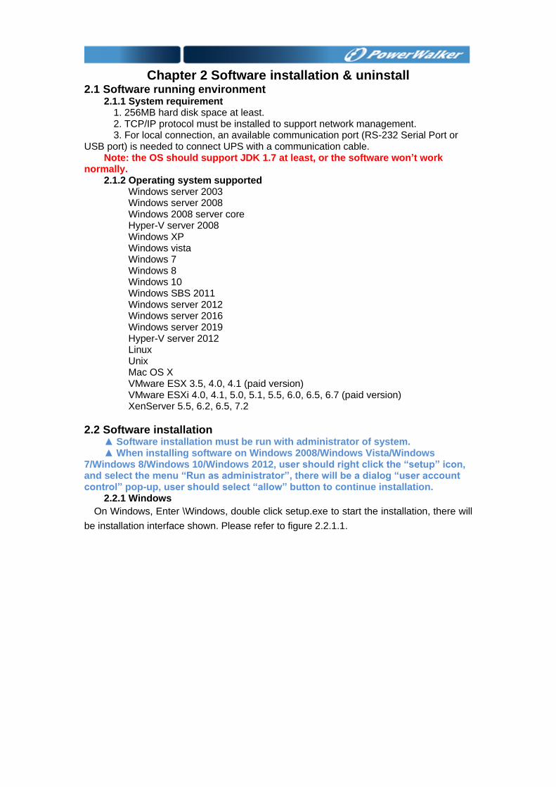
On Windows, Enter \Windows, double click setup.exe to start the installation, there will
be installation interface shown. Please refer to figure 2.2.1.1.
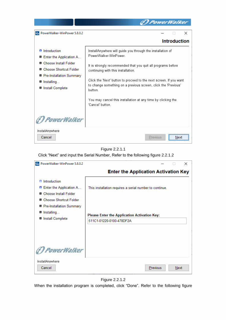
Figure 2.2.1.1
Click “Next” and input the Serial Number, Refer to the following figure 2.2.1.2
Figure 2.2.1.2
When the installation program is completed, click “Done”. Refer to the following figure
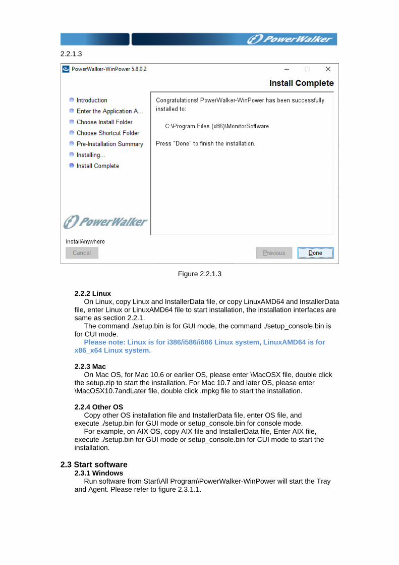
2.2.1.3
Figure 2.2.1.3
2.2.2 Linux On Linux, copy Linux and InstallerData file, or copy LinuxAMD64 and InstallerData
file, enter Linux or LinuxAMD64 file to start installation, the installation interfaces are same as section 2.2.1.
The command ./setup.bin is for GUI mode, the command ./setup_console.bin is for CUI mode.
Please note: Linux is for i386/i586/i686 Linux system, LinuxAMD64 is for x86_x64 Linux system.
2.2.3 Mac On Mac OS, for Mac 10.6 or earlier OS, please enter \MacOSX file, double click
the setup.zip to start the installation. For Mac 10.7 and later OS, please enter \MacOSX10.7andLater file, double click .mpkg file to start the installation.
2.2.4 Other OS Copy other OS installation file and InstallerData file, enter OS file, and
execute ./setup.bin for GUI mode or setup_console.bin for console mode. For example, on AIX OS, copy AIX file and InstallerData file, Enter AIX file,
execute ./setup.bin for GUI mode or setup_console.bin for CUI mode to start the installation.
2.3 Start software 2.3.1 Windows
Run software from Start\All Program\PowerWalker-WinPower will start the Tray and Agent. Please refer to figure 2.3.1.1.
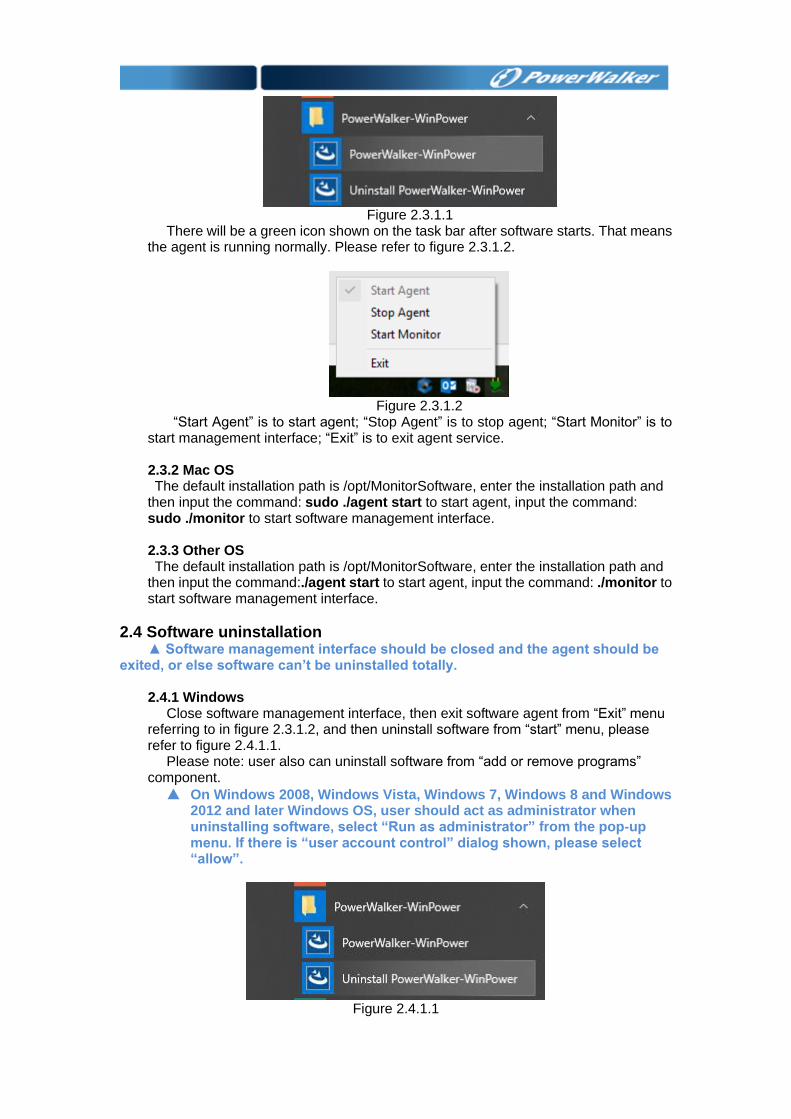
Figure 2.3.1.1
There will be a green icon shown on the task bar after software starts. That means the agent is running normally. Please refer to figure 2.3.1.2.
Figure 2.3.1.2
“Start Agent” is to start agent; “Stop Agent” is to stop agent; “Start Monitor” is to start management interface; “Exit” is to exit agent service. 2.3.2 Mac OS The default installation path is /opt/MonitorSoftware, enter the installation path and
then input the command: sudo ./agent start to start agent, input the command: sudo ./monitor to start software management interface. 2.3.3 Other OS The default installation path is /opt/MonitorSoftware, enter the installation path and
then input the command:./agent start to start agent, input the command: ./monitor to start software management interface.
2.4 Software uninstallation ▲ Software management interface should be closed and the agent should be
exited, or else software can’t be uninstalled totally. 2.4.1 Windows
Close software management interface, then exit software agent from “Exit” menu referring to in figure 2.3.1.2, and then uninstall software from “start” menu, please refer to figure 2.4.1.1.
Please note: user also can uninstall software from “add or remove programs” component.
▲ On Windows 2008, Windows Vista, Windows 7, Windows 8 and Windows 2012 and later Windows OS, user should act as administrator when uninstalling software, select “Run as administrator” from the pop-up menu. If there is “user account control” dialog shown, please select “allow”.
Figure 2.4.1.1
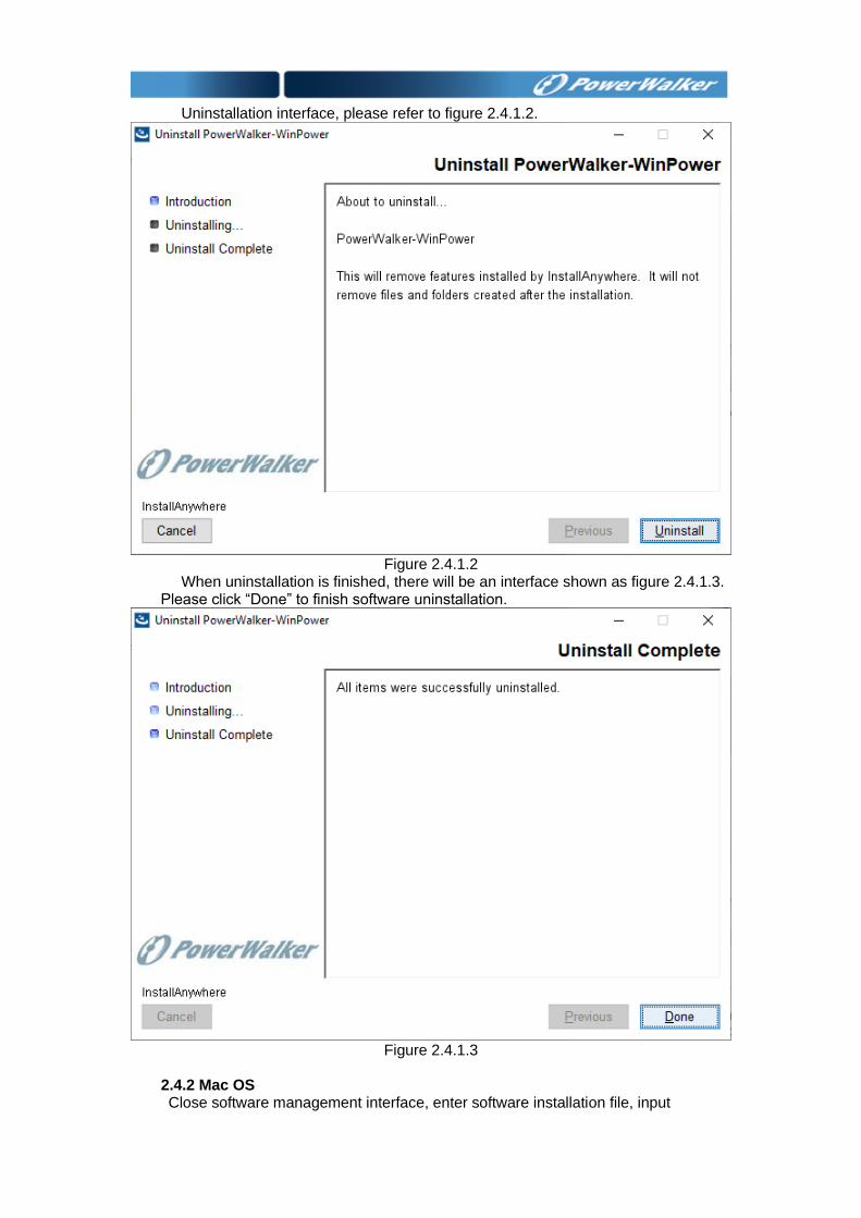
Uninstallation interface, please refer to figure 2.4.1.2.
Figure 2.4.1.2
When uninstallation is finished, there will be an interface shown as figure 2.4.1.3. Please click “Done” to finish software uninstallation.
Figure 2.4.1.3
2.4.2 Mac OS Close software management interface, enter software installation file, input

command: sudo ./agent stop to stop software agent, and then input command: sudo ./Uninstall to uninstall software.
2.4.3 Other OS Close software management interface, enter software installation file, input
command:./agent stop to stop software agent, and then input command:./Uninstall to uninstall software.
Chapter 3 Main functions introduction
3.1 Software management 3.1.1 Be software administrator and modify password
▲If the user wants to configure software setting, user should be administrator of the software first. The default right is read-only, can’t configure settings.
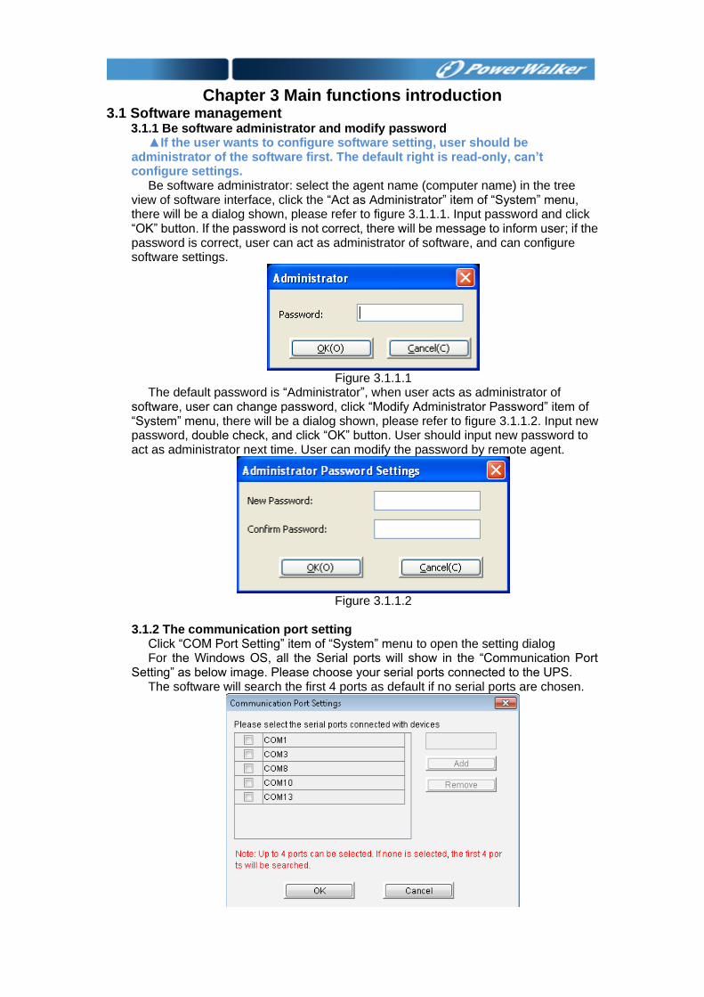
Be software administrator: select the agent name (computer name) in the tree view of software interface, click the “Act as Administrator” item of “System” menu, there will be a dialog shown, please refer to figure 3.1.1.1. Input password and click “OK” button. If the password is not correct, there will be message to inform user; if the password is correct, user can act as administrator of software, and can configure software settings.
Figure 3.1.1.1
The default password is “Administrator”, when user acts as administrator of software, user can change password, click “Modify Administrator Password” item of “System” menu, there will be a dialog shown, please refer to figure 3.1.1.2. Input new password, double check, and click “OK” button. User should input new password to act as administrator next time. User can modify the password by remote agent.
Figure 3.1.1.2
3.1.2 The communication port setting
Click “COM Port Setting” item of “System” menu to open the setting dialog For the Windows OS, all the Serial ports will show in the “Communication Port
Setting” as below image. Please choose your serial ports connected to the UPS. The software will search the first 4 ports as default if no serial ports are chosen.
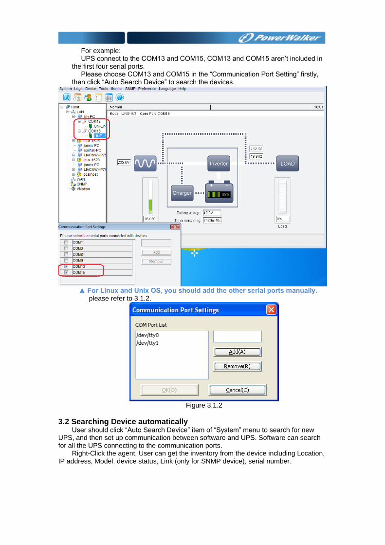
For example: UPS connect to the COM13 and COM15, COM13 and COM15 aren’t included in
the first four serial ports. Please choose COM13 and COM15 in the “Communication Port Setting” firstly,
then click “Auto Search Device” to search the devices.
▲ For Linux and Unix OS, you should add the other serial ports manually.
please refer to 3.1.2.
Figure 3.1.2
3.2 Searching Device automatically User should click “Auto Search Device” item of “System” menu to search for new
UPS, and then set up communication between software and UPS. Software can search for all the UPS connecting to the communication ports.
Right-Click the agent, User can get the inventory from the device including Location, IP address, Model, device status, Link (only for SNMP device), serial number.
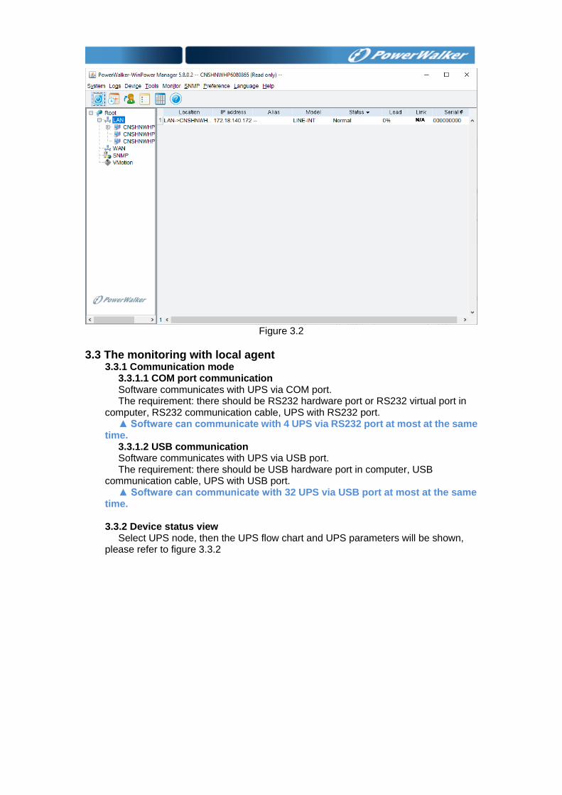
Figure 3.2
3.3 The monitoring with local agent 3.3.1 Communication mode
3.3.1.1 COM port communication Software communicates with UPS via COM port. The requirement: there should be RS232 hardware port or RS232 virtual port in
computer, RS232 communication cable, UPS with RS232 port. ▲ Software can communicate with 4 UPS via RS232 port at most at the same
time. 3.3.1.2 USB communication Software communicates with UPS via USB port. The requirement: there should be USB hardware port in computer, USB
communication cable, UPS with USB port. ▲ Software can communicate with 32 UPS via USB port at most at the same
time.
3.3.2 Device status view Select UPS node, then the UPS flow chart and UPS parameters will be shown,
please refer to figure 3.3.2
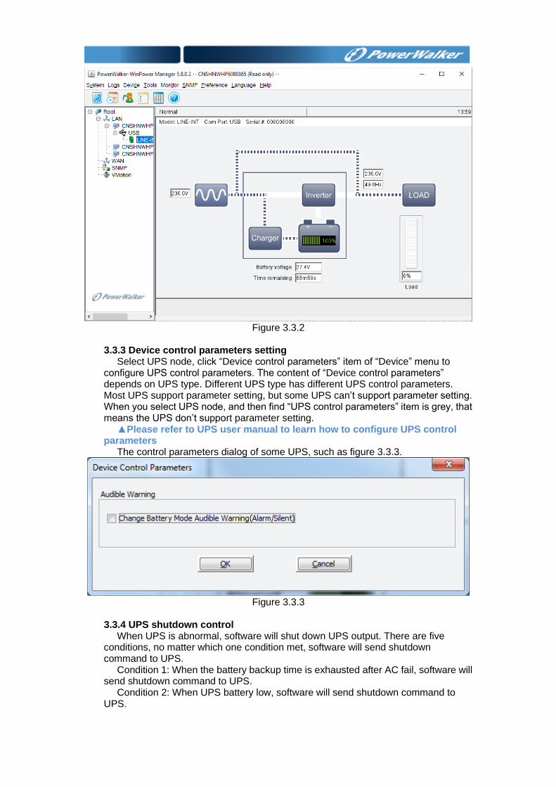
Figure 3.3.2
3.3.3 Device control parameters setting
Select UPS node, click “Device control parameters” item of “Device” menu to configure UPS control parameters. The content of “Device control parameters” depends on UPS type. Different UPS type has different UPS control parameters. Most UPS support parameter setting, but some UPS can’t support parameter setting. When you select UPS node, and then find “UPS control parameters” item is grey, that means the UPS don’t support parameter setting.
▲Please refer to UPS user manual to learn how to configure UPS control parameters
The control parameters dialog of some UPS, such as figure 3.3.3.
Figure 3.3.3
3.3.4 UPS shutdown control
When UPS is abnormal, software will shut down UPS output. There are five conditions, no matter which one condition met, software will send shutdown command to UPS.
Condition 1: When the battery backup time is exhausted after AC fail, software will send shutdown command to UPS.
Condition 2: When UPS battery low, software will send shutdown command to UPS.
Condition 3: When UPS battery capacity is at the setting value or lower, software
will send shutdown command to UPS. Condition 4: When UPS battery remaining time is below the setting value, software
will send shutdown command to UPS. Condition 5: Schedule shutdown UPS output on specific time or weekly.
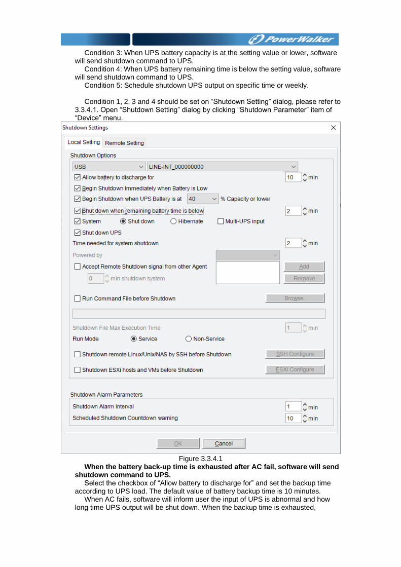
Condition 1, 2, 3 and 4 should be set on “Shutdown Setting” dialog, please refer to
3.3.4.1. Open “Shutdown Setting” dialog by clicking “Shutdown Parameter” item of “Device” menu.
Figure 3.3.4.1
When the battery back-up time is exhausted after AC fail, software will send shutdown command to UPS.
Select the checkbox of “Allow battery to discharge for” and set the backup time according to UPS load. The default value of battery backup time is 10 minutes.
When AC fails, software will inform user the input of UPS is abnormal and how long time UPS output will be shut down. When the backup time is exhausted,
software will send shutdown command to UPS. When the system shutdown need time is exhausted, UPS output will shut down. The default value of system shutdown need time is 2 minutes. So UPS battery should have the ability to supply power to key device for the time, the value of the time should be longer than the value of battery backup time added the value of system shutdown need time.
When UPS battery low, software will send shutdown command to UPS. Select the checkbox of “Begin shutdown immediately when battery is low”, when
AC fails, software will inform user the input of UPS is abnormal and send shutdown command to UPS.
When UPS battery capacity is at the setting value or lower, software will send shutdown command to UPS.
Select the checkbox of “Begin shutdown when UPS battery is at 40% capacity or lower”, when AC fails, software will inform user the input of UPS is abnormal, when UPS battery is 40% or lower, software will send shutdown command to UPS.
When UPS battery remaining time is below the setting value, software will send shutdown command to UPS.
Select the checkbox of “Shut down when remaining battery time is below 2 min”, when AC fails, software will inform user the input of UPS is abnormal, when UPS battery remaining time is below the setting value, software will send shutdown command to UPS.
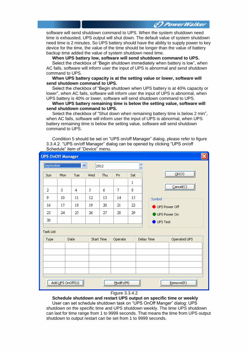
Condition 5 should be set on “UPS on/off Manager” dialog, please refer to figure
3.3.4.2. “UPS on/off Manager” dialog can be opened by clicking “UPS on/off Schedule” item of “Device” menu.
Figure 3.3.4.2
Schedule shutdown and restart UPS output on specific time or weekly User can set schedule shutdown task on “UPS OnOff Manger” dialog: UPS
shutdown on the specific time and UPS shutdown weekly. The time UPS shutdown can last for time range from 1 to 9999 seconds. That means the time from UPS output shutdown to output restart can be set from 1 to 9999 seconds.
The shutdown task list and the calendar are shown on the dialog. On the calendar,
the red point is schedule shutdown task; the green is schedule restart task; the blue point is schedule battery self-test task. User can add schedule shutdown task by “Add UPS OnOff” button, and modify or remove schedule shutdown task by “Modify” or “Remove” button.
▲The time of new task can’t be same as the task that has been added. When schedule task has been added, software will pop up warning dialog to
remind user that UPS will be shut down. The shutdown warning dialog will pop up at the time interval, the warning time interval and the time begin to count down can be set in the “Shutdown Setting” dialog. Please refer to figure 3.3.4.1.
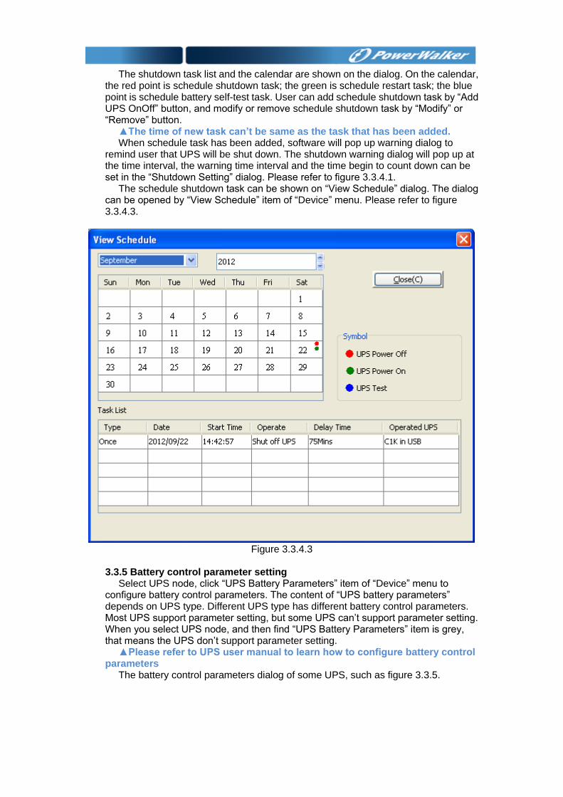
The schedule shutdown task can be shown on “View Schedule” dialog. The dialog can be opened by “View Schedule” item of “Device” menu. Please refer to figure 3.3.4.3.
Figure 3.3.4.3
3.3.5 Battery control parameter setting
Select UPS node, click “UPS Battery Parameters” item of “Device” menu to configure battery control parameters. The content of “UPS battery parameters” depends on UPS type. Different UPS type has different battery control parameters. Most UPS support parameter setting, but some UPS can’t support parameter setting. When you select UPS node, and then find “UPS Battery Parameters” item is grey, that means the UPS don’t support parameter setting.
▲Please refer to UPS user manual to learn how to configure battery control parameters
The battery control parameters dialog of some UPS, such as figure 3.3.5.
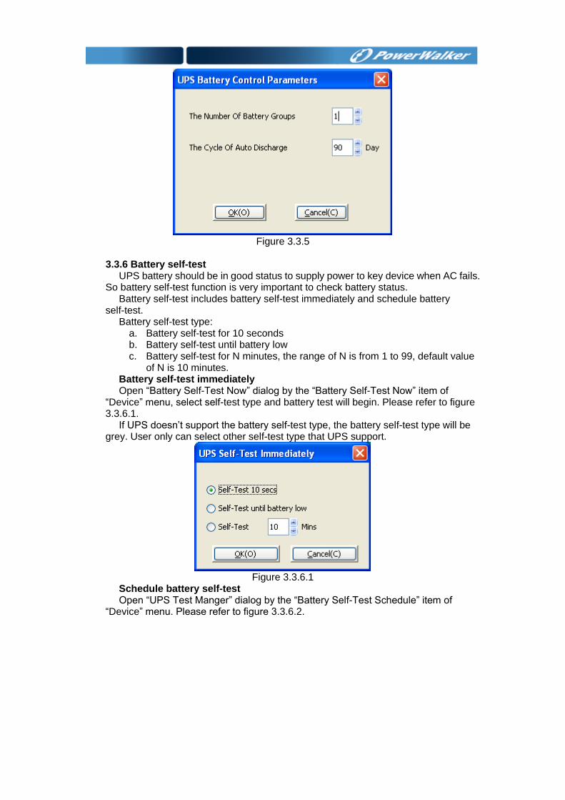
Figure 3.3.5
3.3.6 Battery self-test
UPS battery should be in good status to supply power to key device when AC fails. So battery self-test function is very important to check battery status.
Battery self-test includes battery self-test immediately and schedule battery self-test.
Battery self-test type: a. Battery self-test for 10 seconds b. Battery self-test until battery low c. Battery self-test for N minutes, the range of N is from 1 to 99, default value
of N is 10 minutes. Battery self-test immediately Open “Battery Self-Test Now” dialog by the “Battery Self-Test Now” item of
“Device” menu, select self-test type and battery test will begin. Please refer to figure 3.3.6.1.
If UPS doesn’t support the battery self-test type, the battery self-test type will be grey. User only can select other self-test type that UPS support.
Figure 3.3.6.1
Schedule battery self-test Open “UPS Test Manger” dialog by the “Battery Self-Test Schedule” item of
“Device” menu. Please refer to figure 3.3.6.2.
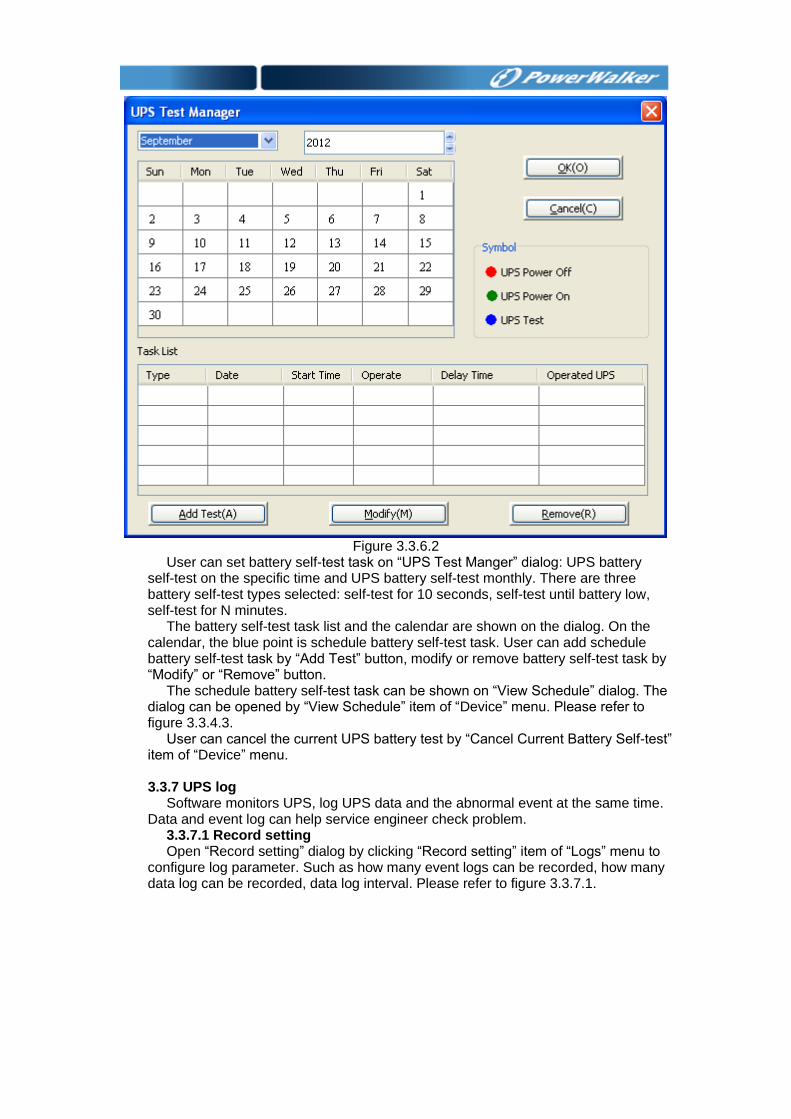
Figure 3.3.6.2
User can set battery self-test task on “UPS Test Manger” dialog: UPS battery self-test on the specific time and UPS battery self-test monthly. There are three battery self-test types selected: self-test for 10 seconds, self-test until battery low, self-test for N minutes.
The battery self-test task list and the calendar are shown on the dialog. On the calendar, the blue point is schedule battery self-test task. User can add schedule battery self-test task by “Add Test” button, modify or remove battery self-test task by “Modify” or “Remove” button.
The schedule battery self-test task can be shown on “View Schedule” dialog. The dialog can be opened by “View Schedule” item of “Device” menu. Please refer to figure 3.3.4.3.
User can cancel the current UPS battery test by “Cancel Current Battery Self-test” item of “Device” menu.
3.3.7 UPS log
Software monitors UPS, log UPS data and the abnormal event at the same time. Data and event log can help service engineer check problem.
3.3.7.1 Record setting Open “Record setting” dialog by clicking “Record setting” item of “Logs” menu to
configure log parameter. Such as how many event logs can be recorded, how many data log can be recorded, data log interval. Please refer to figure 3.3.7.1.
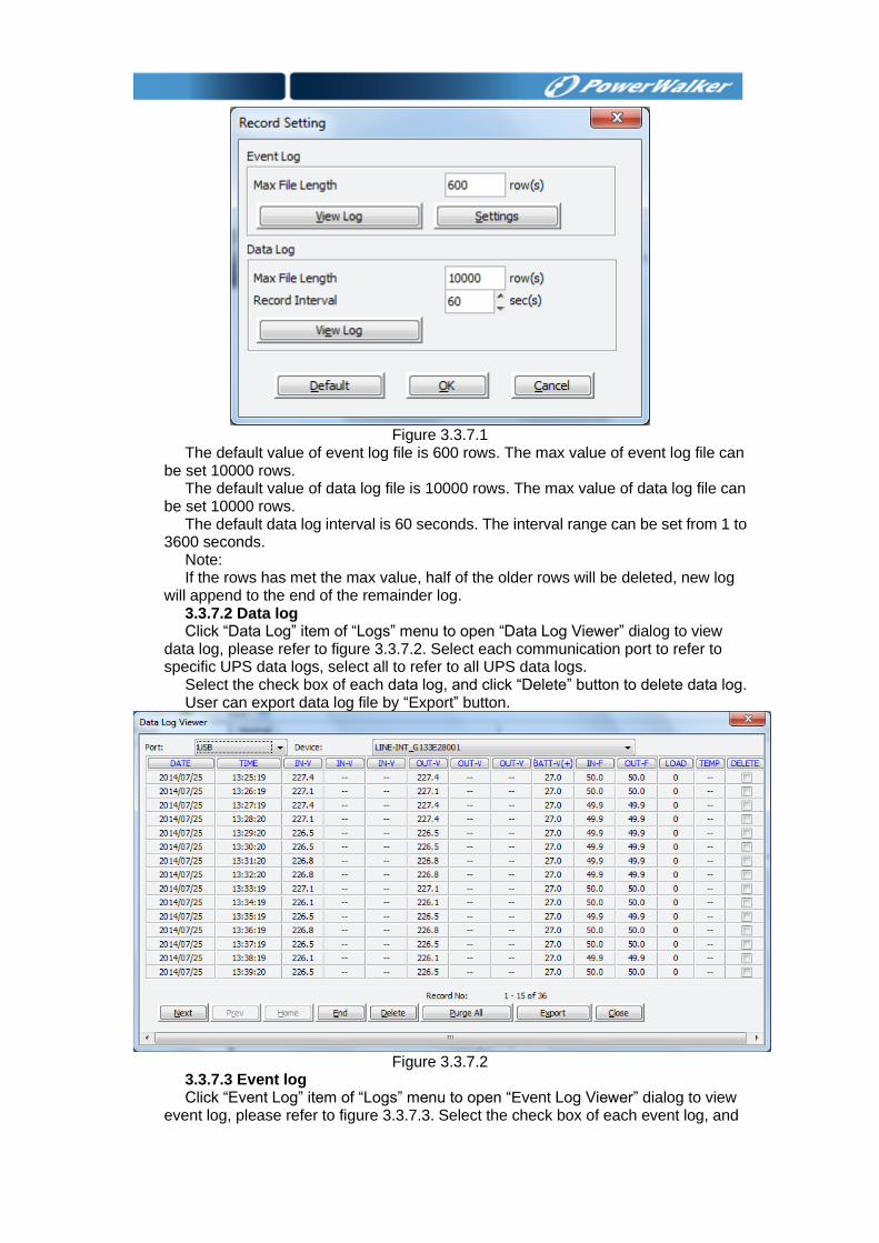
Figure 3.3.7.1
The default value of event log file is 600 rows. The max value of event log file can be set 10000 rows.
The default value of data log file is 10000 rows. The max value of data log file can be set 10000 rows.
The default data log interval is 60 seconds. The interval range can be set from 1 to 3600 seconds.
Note: If the rows has met the max value, half of the older rows will be deleted, new log
will append to the end of the remainder log. 3.3.7.2 Data log Click “Data Log” item of “Logs” menu to open “Data Log Viewer” dialog to view
data log, please refer to figure 3.3.7.2. Select each communication port to refer to specific UPS data logs, select all to refer to all UPS data logs.
Select the check box of each data log, and click “Delete” button to delete data log. User can export data log file by “Export” button.
Figure 3.3.7.2
3.3.7.3 Event log Click “Event Log” item of “Logs” menu to open “Event Log Viewer” dialog to view
event log, please refer to figure 3.3.7.3. Select the check box of each event log, and
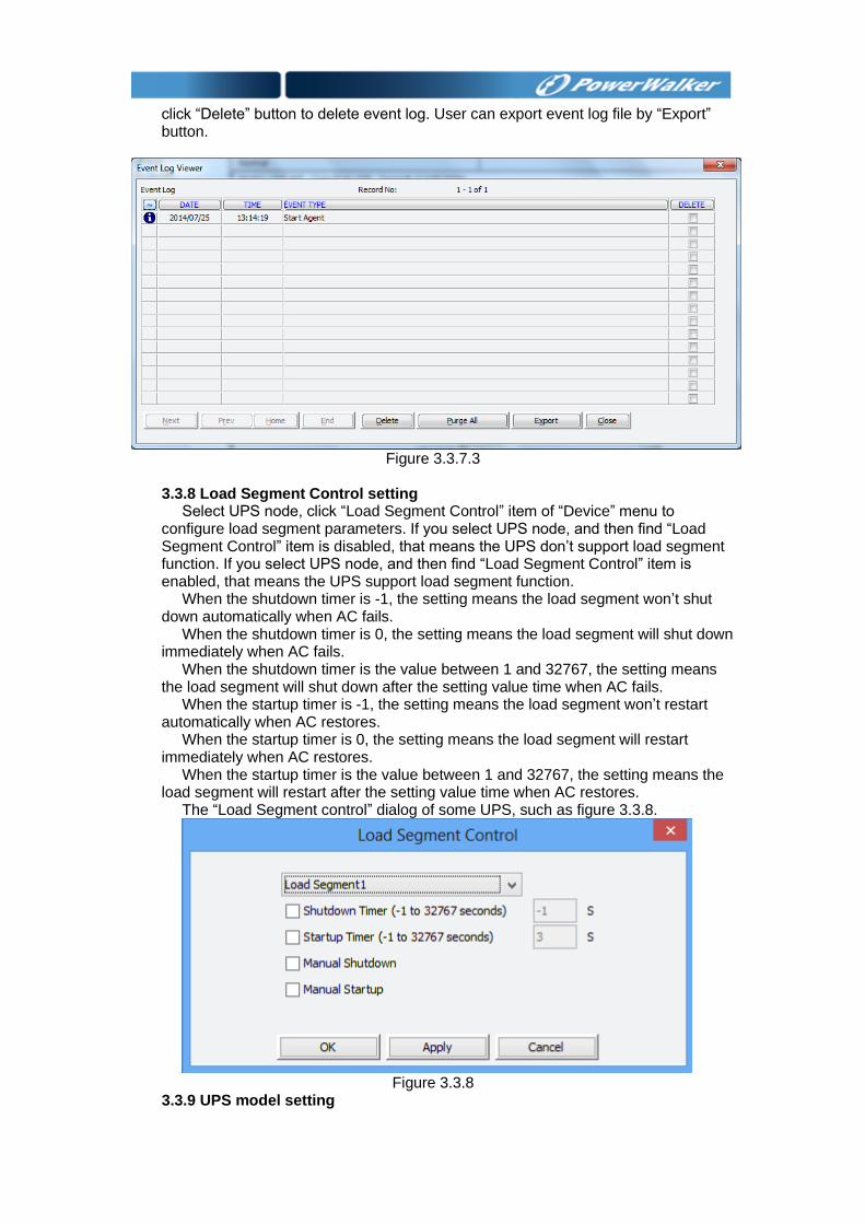
click “Delete” button to delete event log. User can export event log file by “Export” button.
Figure 3.3.7.3
3.3.8 Load Segment Control setting
Select UPS node, click “Load Segment Control” item of “Device” menu to configure load segment parameters. If you select UPS node, and then find “Load Segment Control” item is disabled, that means the UPS don’t support load segment function. If you select UPS node, and then find “Load Segment Control” item is enabled, that means the UPS support load segment function.
When the shutdown timer is -1, the setting means the load segment won’t shut down automatically when AC fails.
When the shutdown timer is 0, the setting means the load segment will shut down immediately when AC fails.
When the shutdown timer is the value between 1 and 32767, the setting means the load segment will shut down after the setting value time when AC fails.
When the startup timer is -1, the setting means the load segment won’t restart automatically when AC restores.
When the startup timer is 0, the setting means the load segment will restart immediately when AC restores.
When the startup timer is the value between 1 and 32767, the setting means the load segment will restart after the setting value time when AC restores.
The “Load Segment control” dialog of some UPS, such as figure 3.3.8.
Figure 3.3.8
3.3.9 UPS model setting
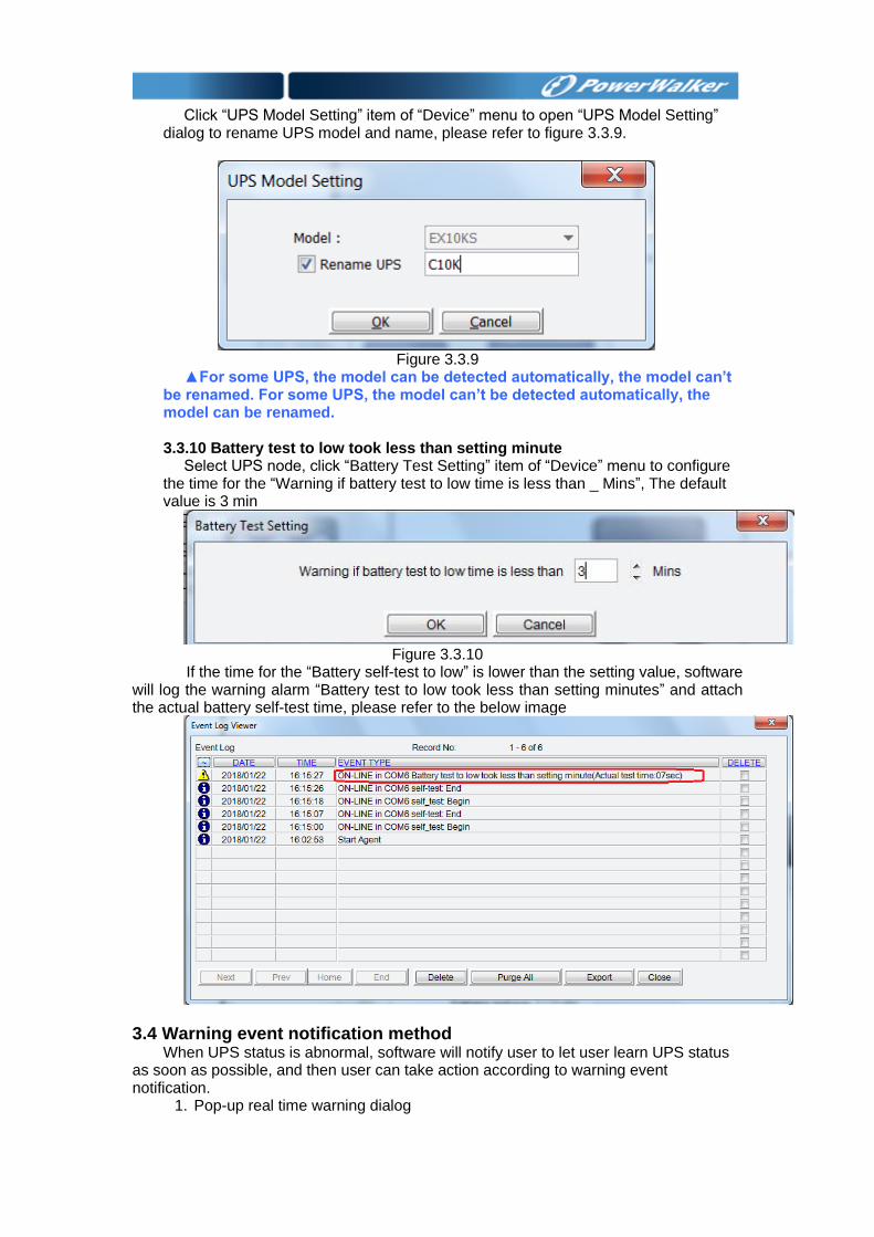
Click “UPS Model Setting” item of “Device” menu to open “UPS Model Setting”
dialog to rename UPS model and name, please refer to figure 3.3.9.
Figure 3.3.9
▲For some UPS, the model can be detected automatically, the model can’t be renamed. For some UPS, the model can’t be detected automatically, the model can be renamed.
3.3.10 Battery test to low took less than setting minute
Select UPS node, click “Battery Test Setting” item of “Device” menu to configure the time for the “Warning if battery test to low time is less than _ Mins”, The default value is 3 min
Figure 3.3.10
If the time for the “Battery self-test to low” is lower than the setting value, software will log the warning alarm “Battery test to low took less than setting minutes” and attach the actual battery self-test time, please refer to the below image
3.4 Warning event notification method When UPS status is abnormal, software will notify user to let user learn UPS status
as soon as possible, and then user can take action according to warning event notification.
1. Pop-up real time warning dialog
2. E-mail message alarm 3. SMS alarm
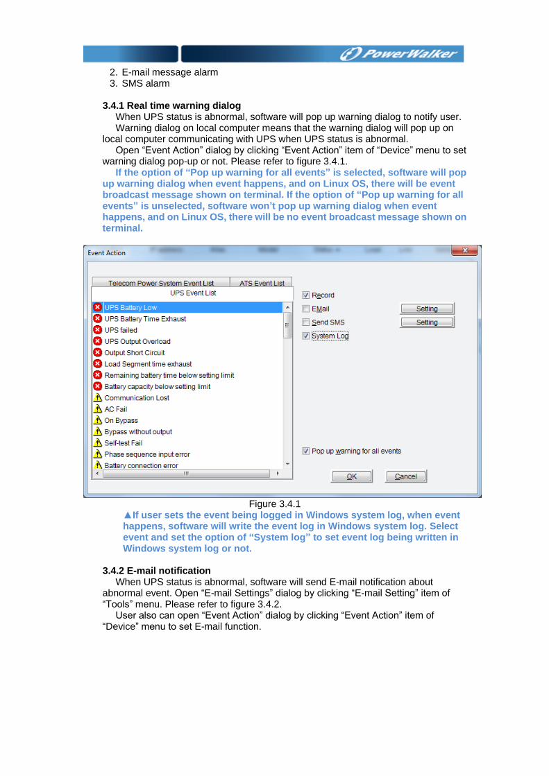
3.4.1 Real time warning dialog When UPS status is abnormal, software will pop up warning dialog to notify user. Warning dialog on local computer means that the warning dialog will pop up on
local computer communicating with UPS when UPS status is abnormal. Open “Event Action” dialog by clicking “Event Action” item of “Device” menu to set
warning dialog pop-up or not. Please refer to figure 3.4.1. If the option of “Pop up warning for all events” is selected, software will pop
up warning dialog when event happens, and on Linux OS, there will be event broadcast message shown on terminal. If the option of “Pop up warning for all events” is unselected, software won’t pop up warning dialog when event happens, and on Linux OS, there will be no event broadcast message shown on terminal.
Figure 3.4.1
▲If user sets the event being logged in Windows system log, when event happens, software will write the event log in Windows system log. Select event and set the option of “System log” to set event log being written in Windows system log or not.
3.4.2 E-mail notification When UPS status is abnormal, software will send E-mail notification about
abnormal event. Open “E-mail Settings” dialog by clicking “E-mail Setting” item of “Tools” menu. Please refer to figure 3.4.2.
User also can open “Event Action” dialog by clicking “Event Action” item of “Device” menu to set E-mail function.
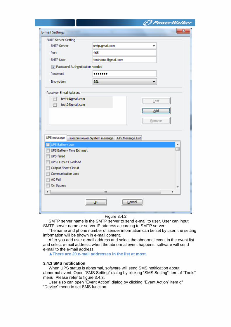
Figure 3.4.2
SMTP server name is the SMTP server to send e-mail to user. User can input SMTP server name or server IP address according to SMTP server.
The name and phone number of sender information can be set by user, the setting information will be shown in e-mail content.
After you add user e-mail address and select the abnormal event in the event list and select e-mail address, when the abnormal event happens, software will send e-mail to the e-mail address.
▲There are 20 e-mail addresses in the list at most.
3.4.3 SMS notification When UPS status is abnormal, software will send SMS notification about
abnormal event. Open “SMS Setting” dialog by clicking “SMS Setting” item of “Tools” menu. Please refer to figure 3.4.3.
User also can open “Event Action” dialog by clicking “Event Action” item of “Device” menu to set SMS function.
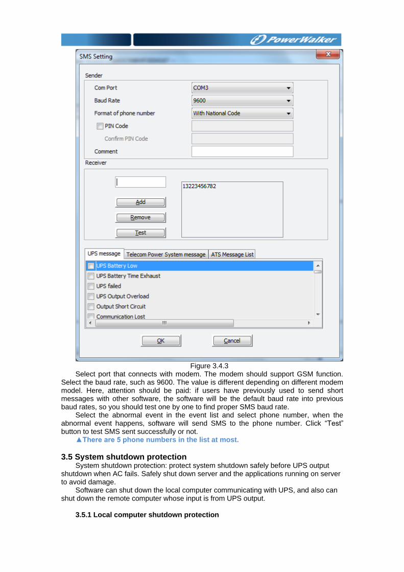
Figure 3.4.3
Select port that connects with modem. The modem should support GSM function. Select the baud rate, such as 9600. The value is different depending on different modem model. Here, attention should be paid: if users have previously used to send short messages with other software, the software will be the default baud rate into previous baud rates, so you should test one by one to find proper SMS baud rate.
Select the abnormal event in the event list and select phone number, when the abnormal event happens, software will send SMS to the phone number. Click “Test” button to test SMS sent successfully or not.
▲There are 5 phone numbers in the list at most.
3.5 System shutdown protection System shutdown protection: protect system shutdown safely before UPS output
shutdown when AC fails. Safely shut down server and the applications running on server to avoid damage.
Software can shut down the local computer communicating with UPS, and also can shut down the remote computer whose input is from UPS output.
3.5.1 Local computer shutdown protection
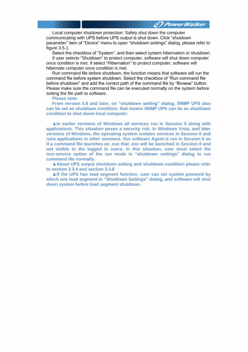
Local computer shutdown protection: Safely shut down the computer
communicating with UPS before UPS output is shut down. Click “shutdown parameter” item of “Device” menu to open “shutdown settings” dialog, please refer to figure 3.5.1.
Select the checkbox of “System”, and then select system hibernation or shutdown. If user selects “Shutdown” to protect computer, software will shut down computer
once condition is met. If select “Hibernation” to protect computer, software will hibernate computer once condition is met.
Run command file before shutdown, the function means that software will run the command file before system shutdown. Select the checkbox of “Run command file before shutdown” and add the correct path of the command file by “Browse” button. Please make sure the command file can be executed normally on the system before setting the file path to software.
Please note: From version 5.8 and later, on “shutdown setting” dialog, SNMP UPS also
can be set as shutdown condition, that means SNMP UPS can be as shutdown condition to shut down local computer.
▲In earlier versions of Windows all services run in Session 0 along with
applications. This situation poses a security risk. In Windows Vista, and later versions of Windows, the operating system isolates services in Session 0 and runs applications in other sessions. Our software Agent is run in Session 0 so if a command file launches an .exe that .exe will be launched in Session 0 and not visible to the logged in users. In this situation, user must select the non-service option of the run mode in “shutdown settings” dialog to run command file normally.
▲About UPS output shutdown setting and shutdown condition please refer to section 3.3.4 and section 3.3.8
▲If the UPS has load segment function, user can set system powered by which one load segment in “Shutdown Settings” dialog, and software will shut down system before load segment shutdown.
Figure 3.5.1
3.5.2 Remote computer shutdown protection
Remote computer shutdown protection: software installed on local computer will send shutdown command to safely shut down the remote computers before UPS output is shut down.
Settings of local computer communicating with UPS: When software wants to shut down the remote computer, software communicating
with UPS should set the condition and the IP address of remote to shut down remote computer, when the condition is met, software will send shutdown command to remote computer. For example: if the remote computers IP are 172.18.139.51. User can set the remote computers shutdown condition by “Add” button. Please refer to figure 3.5.2.1. User can select the shutdown condition and then modify or delete the condition by “Modify” button and “Delete” button.
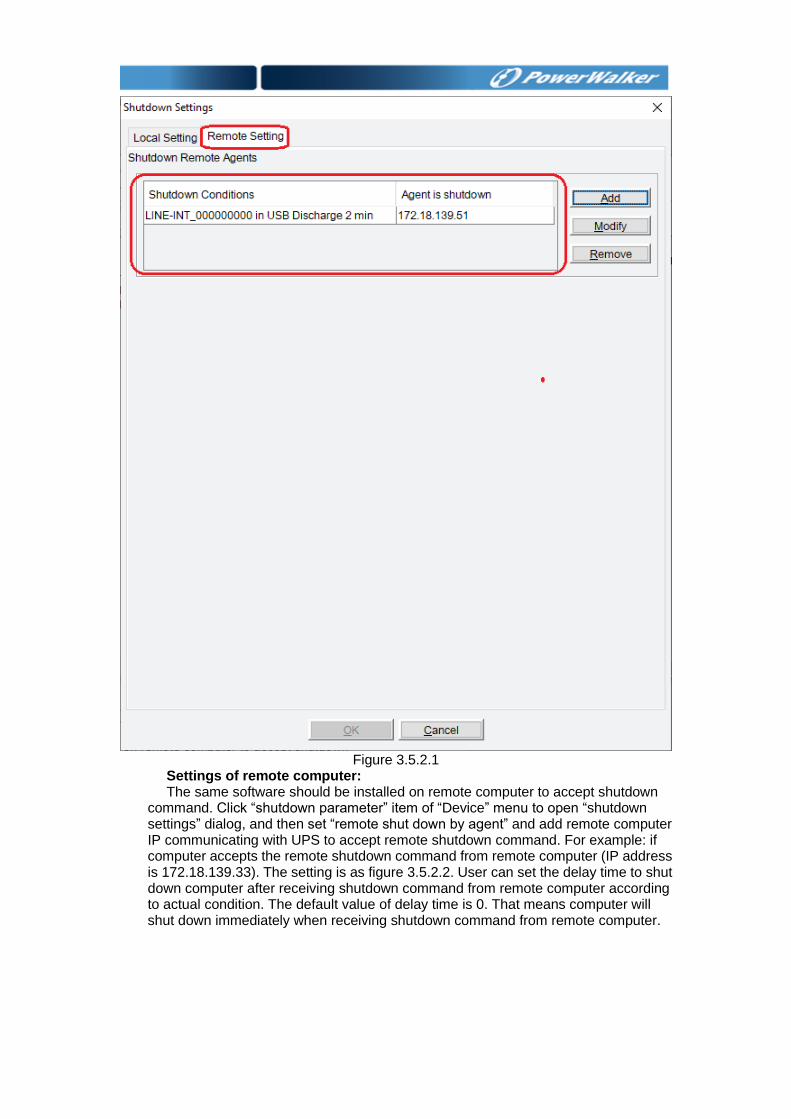
Figure 3.5.2.1
Settings of remote computer: The same software should be installed on remote computer to accept shutdown
command. Click “shutdown parameter” item of “Device” menu to open “shutdown settings” dialog, and then set “remote shut down by agent” and add remote computer IP communicating with UPS to accept remote shutdown command. For example: if computer accepts the remote shutdown command from remote computer (IP address is 172.18.139.33). The setting is as figure 3.5.2.2. User can set the delay time to shut down computer after receiving shutdown command from remote computer according to actual condition. The default value of delay time is 0. That means computer will shut down immediately when receiving shutdown command from remote computer.
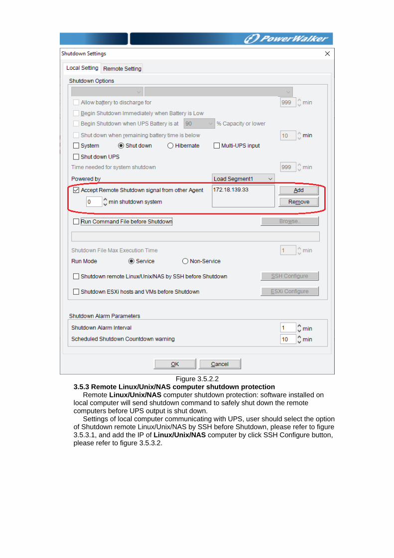
Figure 3.5.2.2
3.5.3 Remote Linux/Unix/NAS computer shutdown protection Remote Linux/Unix/NAS computer shutdown protection: software installed on
local computer will send shutdown command to safely shut down the remote computers before UPS output is shut down.
Settings of local computer communicating with UPS, user should select the option of Shutdown remote Linux/Unix/NAS by SSH before Shutdown, please refer to figure 3.5.3.1, and add the IP of Linux/Unix/NAS computer by click SSH Configure button, please refer to figure 3.5.3.2.
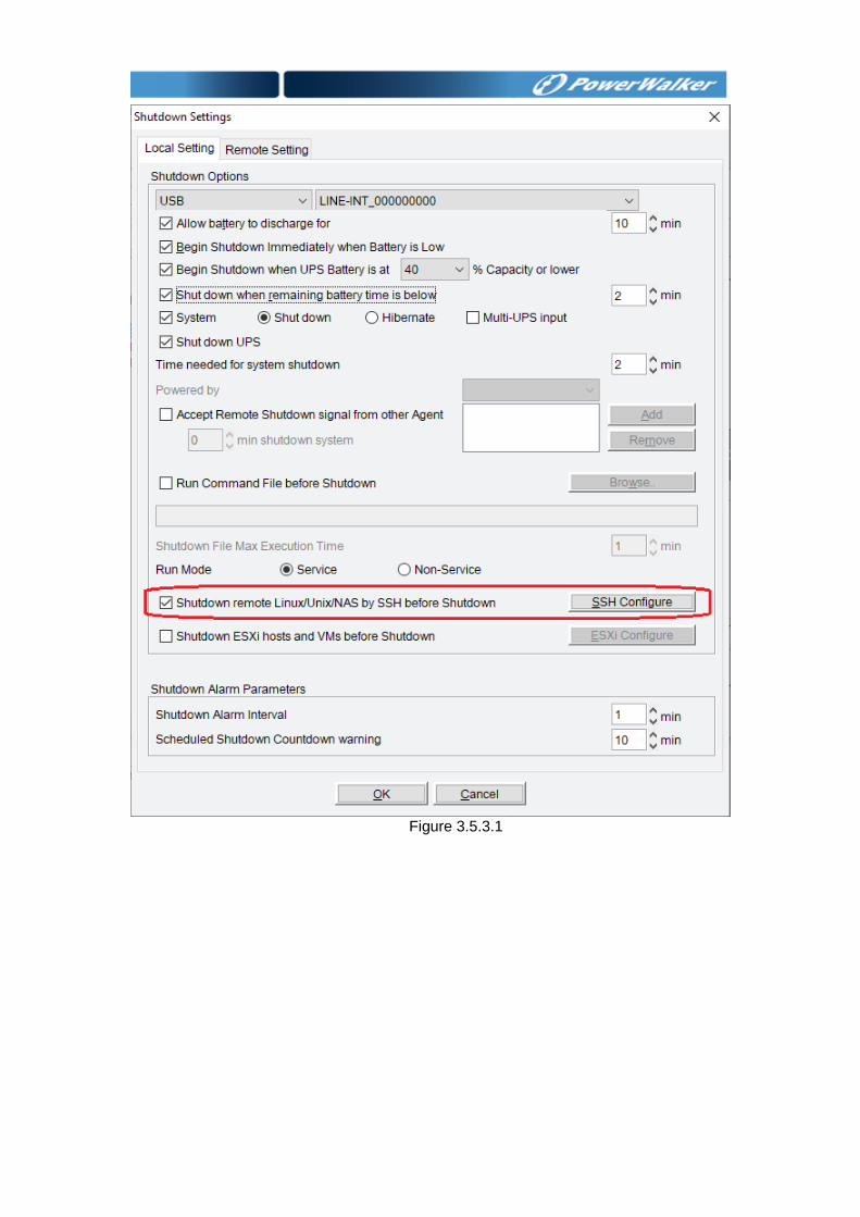
Figure 3.5.3.1
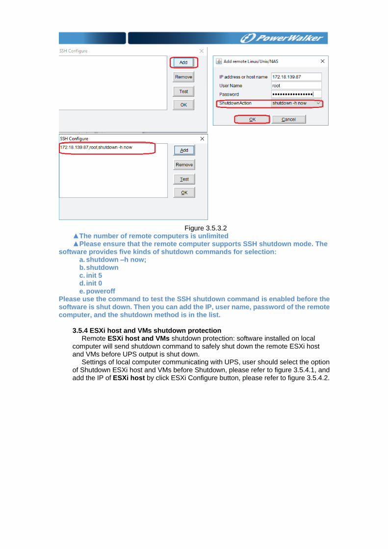
Figure 3.5.3.2
▲The number of remote computers is unlimited ▲Please ensure that the remote computer supports SSH shutdown mode. The
software provides five kinds of shutdown commands for selection: a. shutdown –h now; b. shutdown c. init 5 d. init 0 e. poweroff
Please use the command to test the SSH shutdown command is enabled before the software is shut down. Then you can add the IP, user name, password of the remote computer, and the shutdown method is in the list.
3.5.4 ESXi host and VMs shutdown protection Remote ESXi host and VMs shutdown protection: software installed on local
computer will send shutdown command to safely shut down the remote ESXi host and VMs before UPS output is shut down.
Settings of local computer communicating with UPS, user should select the option of Shutdown ESXi host and VMs before Shutdown, please refer to figure 3.5.4.1, and add the IP of ESXi host by click ESXi Configure button, please refer to figure 3.5.4.2.
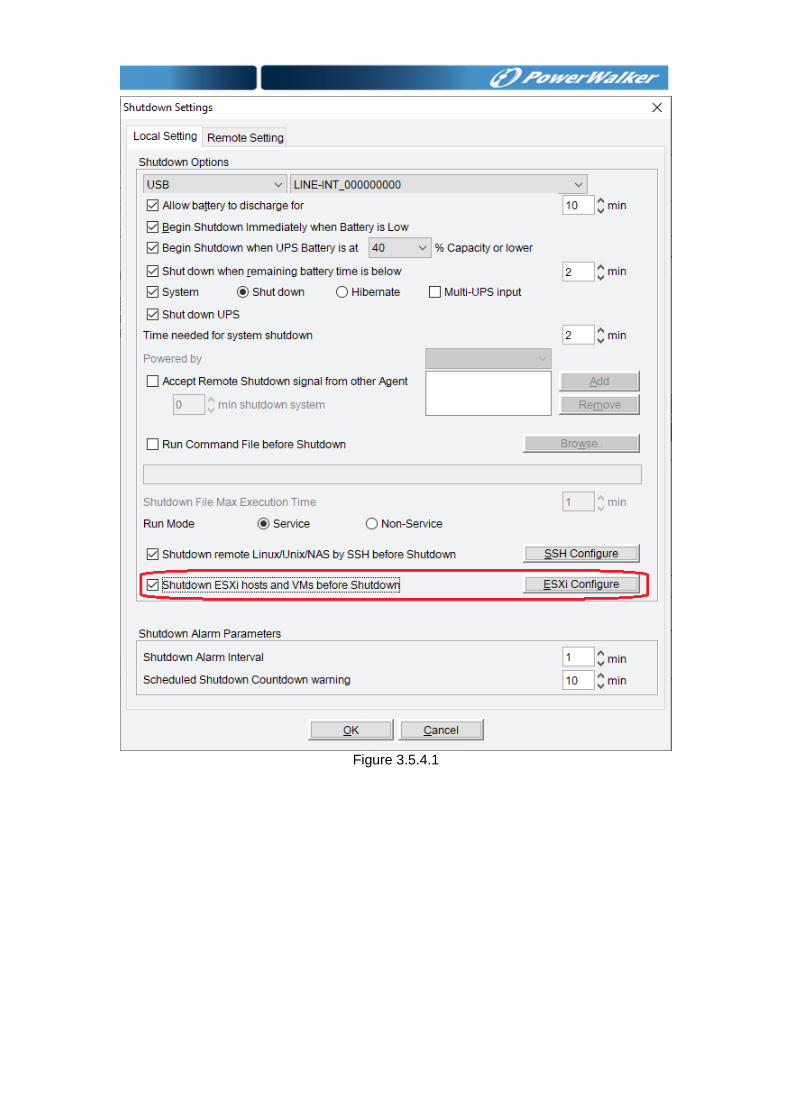
Figure 3.5.4.1
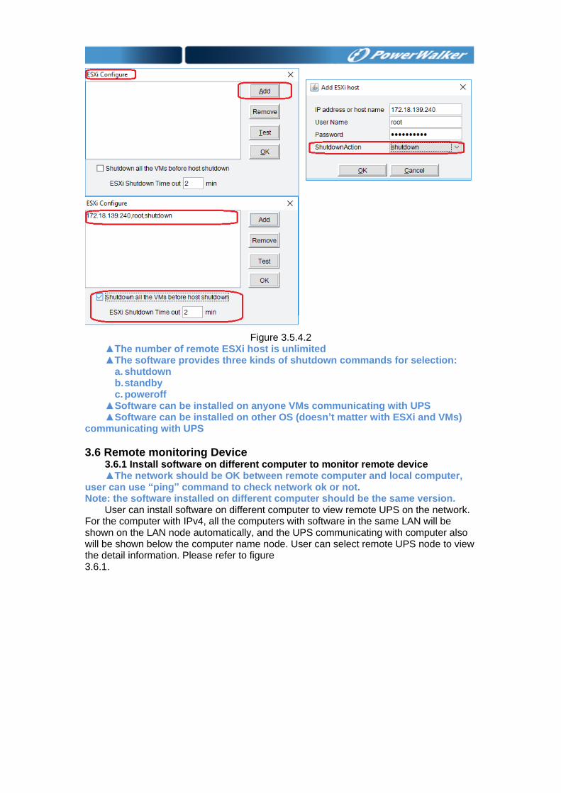
Figure 3.5.4.2
▲The number of remote ESXi host is unlimited ▲The software provides three kinds of shutdown commands for selection:
a. shutdown b. standby c. poweroff
▲Software can be installed on anyone VMs communicating with UPS ▲Software can be installed on other OS (doesn’t matter with ESXi and VMs)
communicating with UPS
3.6 Remote monitoring Device 3.6.1 Install software on different computer to monitor remote device ▲The network should be OK between remote computer and local computer,
user can use “ping” command to check network ok or not. Note: the software installed on different computer should be the same version.
User can install software on different computer to view remote UPS on the network. For the computer with IPv4, all the computers with software in the same LAN will be shown on the LAN node automatically, and the UPS communicating with computer also will be shown below the computer name node. User can select remote UPS node to view the detail information. Please refer to figure 3.6.1.
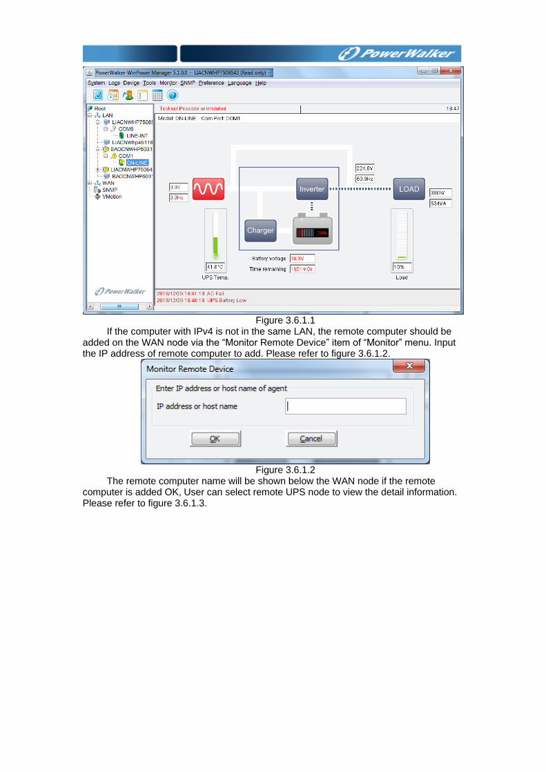
Figure 3.6.1.1
If the computer with IPv4 is not in the same LAN, the remote computer should be added on the WAN node via the “Monitor Remote Device” item of “Monitor” menu. Input the IP address of remote computer to add. Please refer to figure 3.6.1.2.
Figure 3.6.1.2
The remote computer name will be shown below the WAN node if the remote computer is added OK, User can select remote UPS node to view the detail information. Please refer to figure 3.6.1.3.
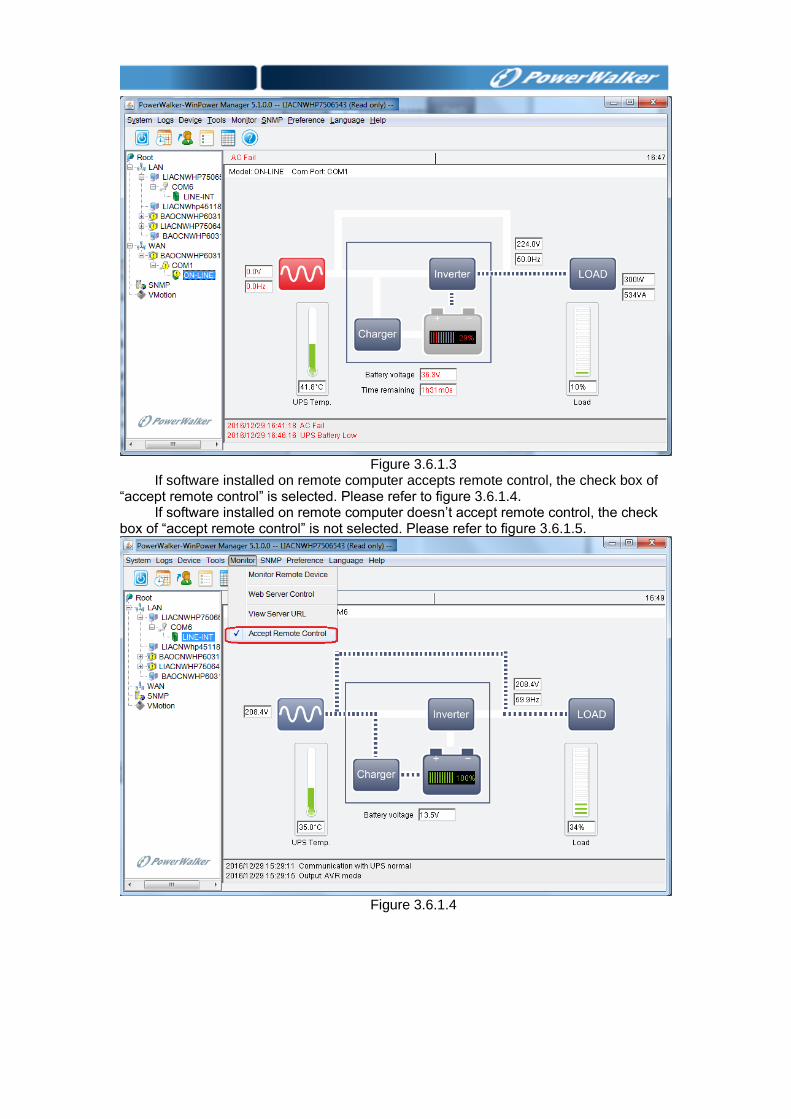
Figure 3.6.1.3
If software installed on remote computer accepts remote control, the check box of “accept remote control” is selected. Please refer to figure 3.6.1.4.
If software installed on remote computer doesn’t accept remote control, the check box of “accept remote control” is not selected. Please refer to figure 3.6.1.5.
Figure 3.6.1.4
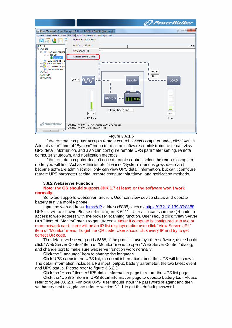
Figure 3.6.1.5
If the remote computer accepts remote control, select computer node, click “Act as Administrator” item of “System” menu to become software administrator, user can view UPS detail information, and also can configure remote UPS parameter setting, remote computer shutdown, and notification methods.
If the remote computer doesn’t accept remote control, select the remote computer node, you will find “Act as Administrator” item of “System” menu is grey, user can’t become software administrator, only can view UPS detail information, but can’t configure remote UPS parameter setting, remote computer shutdown, and notification methods.
3.6.2 Webserver Function Note: the OS should support JDK 1.7 at least, or the software won’t work
normally. Software supports webserver function. User can view device status and operate
battery test via mobile phone. Input the web address: https://IP address:8888, such as https://172.18.139.80:8888.
UPS list will be shown. Please refer to figure 3.6.2.1. User also can scan the QR code to access to web address with the browser scanning function. User should click “View Server URL” item of “Monitor” menu to get QR code. Note: if computer is configured with two or more network card, there will be an IP list displayed after user click “View Server URL” item of “Monitor” menu. To get the QR code, User should click every IP and try to get correct QR code.
The default webserver port is 8888, if the port is in use by other software, user should click “Web Server Control” item of “Monitor” menu to open “Web Server Control” dialog, and change port to make sure webserver function work normally.
Click the “Language” item to change the language. Click UPS name in the UPS list, the detail information about the UPS will be shown.
The detail information includes UPS input, output, battery parameter, the two latest event and UPS status. Please refer to figure 3.6.2.2.
Click the “Home” item in UPS detail information page to return the UPS list page. Click the “Control” item in UPS detail information page to operate battery test. Please
refer to figure 3.6.2.3. For local UPS, user should input the password of agent and then set battery test task, please refer to section 3.1.1 to get the default password.
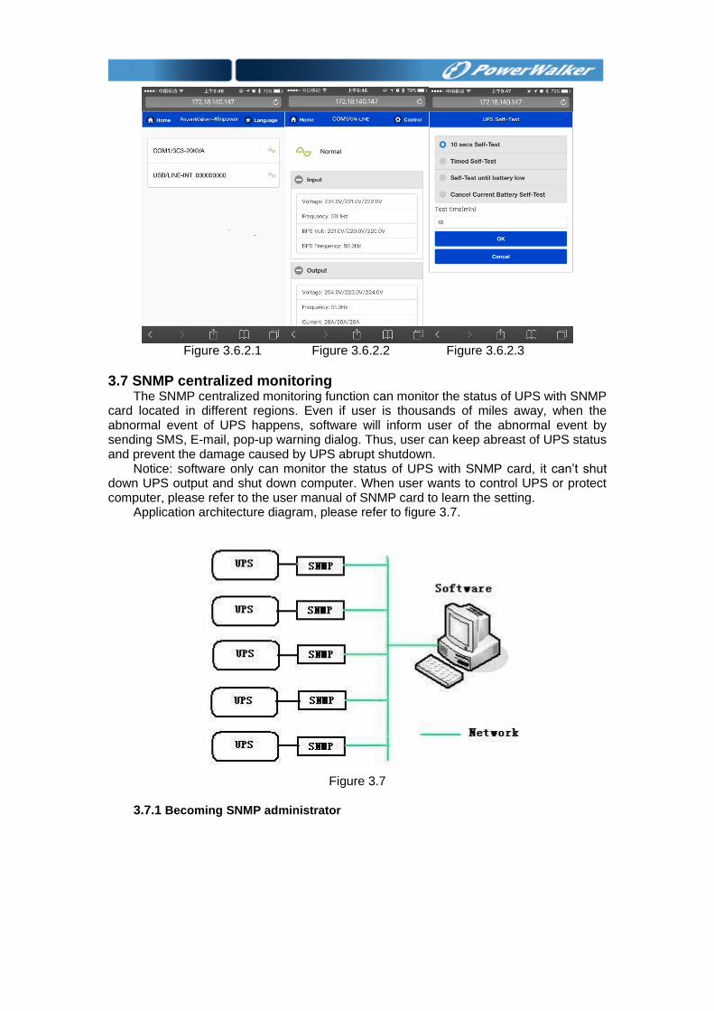
Figure 3.6.2.1 Figure 3.6.2.2 Figure 3.6.2.3
3.7 SNMP centralized monitoring The SNMP centralized monitoring function can monitor the status of UPS with SNMP
card located in different regions. Even if user is thousands of miles away, when the abnormal event of UPS happens, software will inform user of the abnormal event by sending SMS, E-mail, pop-up warning dialog. Thus, user can keep abreast of UPS status and prevent the damage caused by UPS abrupt shutdown.
Notice: software only can monitor the status of UPS with SNMP card, it can’t shut down UPS output and shut down computer. When user wants to control UPS or protect computer, please refer to the user manual of SNMP card to learn the setting.
Application architecture diagram, please refer to figure 3.7.
Figure 3.7
3.7.1 Becoming SNMP administrator
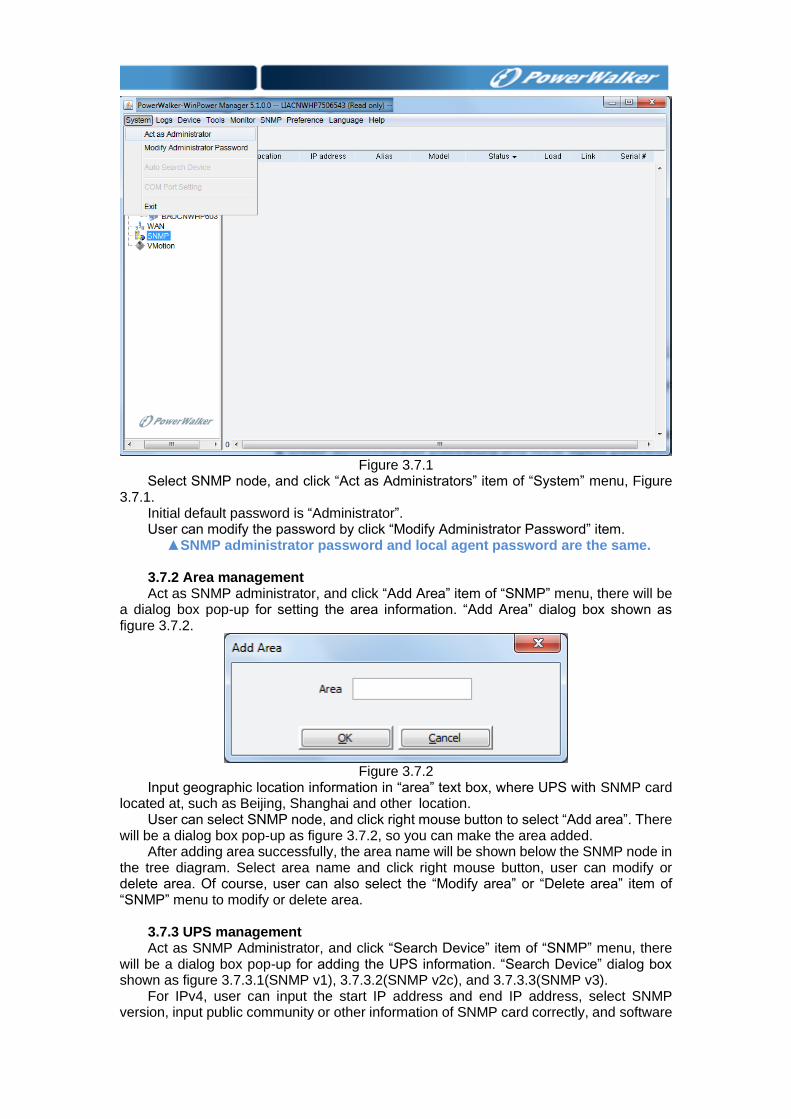
Figure 3.7.1
Select SNMP node, and click “Act as Administrators” item of “System” menu, Figure 3.7.1.
Initial default password is “Administrator”. User can modify the password by click “Modify Administrator Password” item.
▲SNMP administrator password and local agent password are the same.
3.7.2 Area management Act as SNMP administrator, and click “Add Area” item of “SNMP” menu, there will be
a dialog box pop-up for setting the area information. “Add Area” dialog box shown as figure 3.7.2.
Figure 3.7.2
Input geographic location information in “area” text box, where UPS with SNMP card located at, such as Beijing, Shanghai and other location.
User can select SNMP node, and click right mouse button to select “Add area”. There will be a dialog box pop-up as figure 3.7.2, so you can make the area added.
After adding area successfully, the area name will be shown below the SNMP node in the tree diagram. Select area name and click right mouse button, user can modify or delete area. Of course, user can also select the “Modify area” or “Delete area” item of “SNMP” menu to modify or delete area.
3.7.3 UPS management Act as SNMP Administrator, and click “Search Device” item of “SNMP” menu, there
will be a dialog box pop-up for adding the UPS information. “Search Device” dialog box shown as figure 3.7.3.1(SNMP v1), 3.7.3.2(SNMP v2c), and 3.7.3.3(SNMP v3).
For IPv4, user can input the start IP address and end IP address, select SNMP version, input public community or other information of SNMP card correctly, and software
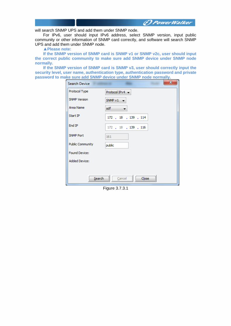
will search SNMP UPS and add them under SNMP node.
For IPv6, user should input IPv6 address, select SNMP version, input public community or other information of SNMP card correctly, and software will search SNMP UPS and add them under SNMP node.
▲Please note: If the SNMP version of SNMP card is SNMP v1 or SNMP v2c, user should input
the correct public community to make sure add SNMP device under SNMP node normally.
If the SNMP version of SNMP card is SNMP v3, user should correctly input the security level, user name, authentication type, authentication password and private password to make sure add SNMP device under SNMP node normally.
Figure 3.7.3.1
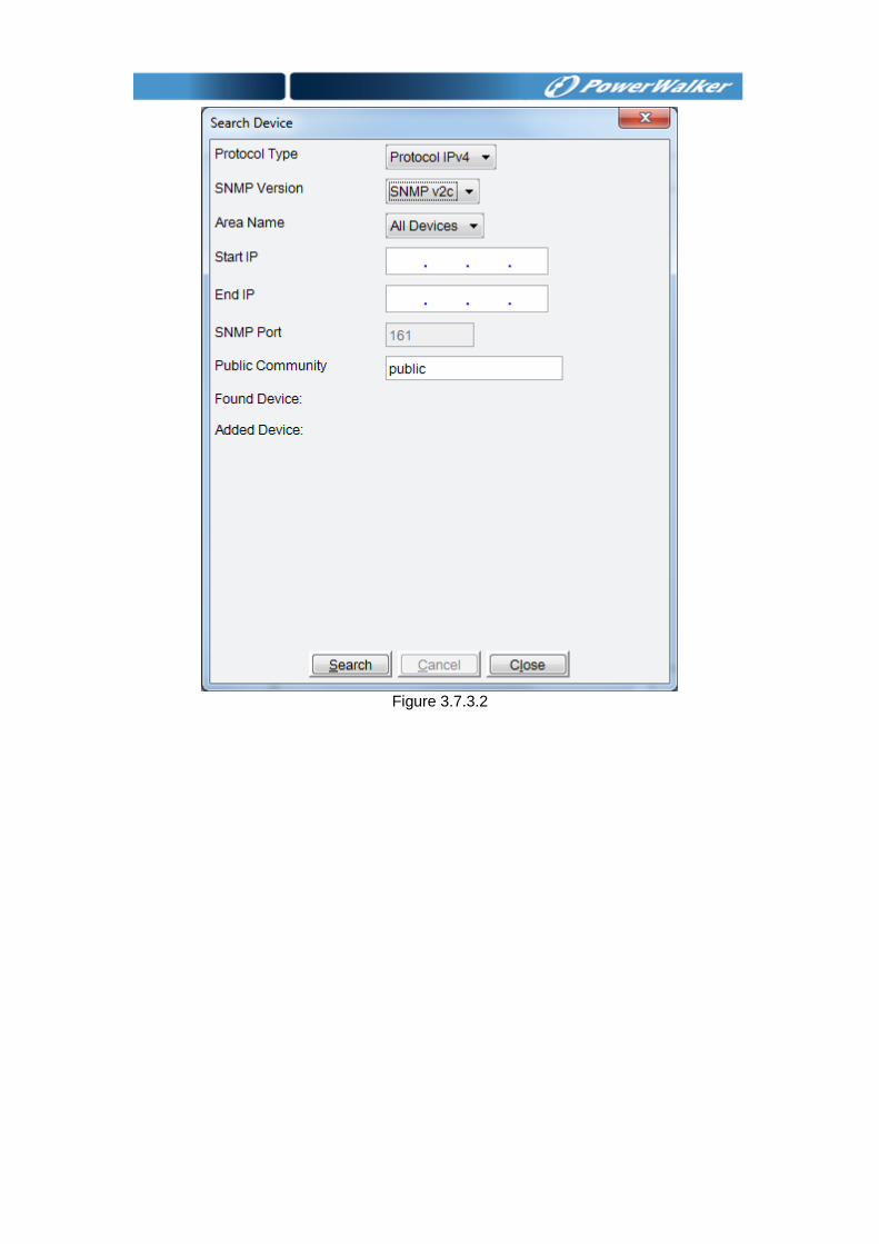
Figure 3.7.3.2
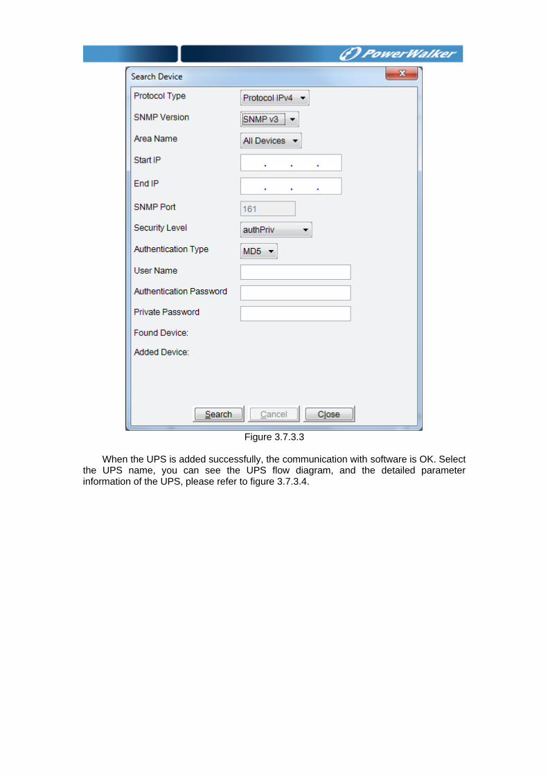
Figure 3.7.3.3
When the UPS is added successfully, the communication with software is OK. Select
the UPS name, you can see the UPS flow diagram, and the detailed parameter information of the UPS, please refer to figure 3.7.3.4.
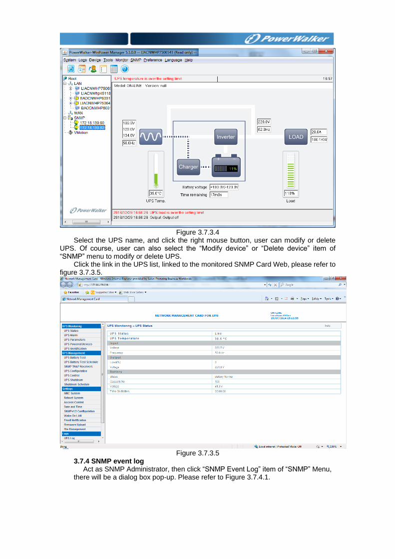
Figure 3.7.3.4
Select the UPS name, and click the right mouse button, user can modify or delete UPS. Of course, user can also select the “Modify device” or “Delete device” item of “SNMP” menu to modify or delete UPS.
Click the link in the UPS list, linked to the monitored SNMP Card Web, please refer to figure 3.7.3.5.
Figure 3.7.3.5
3.7.4 SNMP event log Act as SNMP Administrator, then click “SNMP Event Log” item of “SNMP” Menu,
there will be a dialog box pop-up. Please refer to Figure 3.7.4.1.
Figure 3.7.4.1
Click “Export” button to export all alarm event. SNMP event record maximum length can be set. Act as SNMP Administrator, then
click “Event Log Setting” item of “SNMP” Menu, there will be a dialog pop-up, as Figure 3.7.4.2. The default value is 5000, Maximum can be set 100000.
When the record exceeds the maximum, Software will delete the oldest event to record a new event automatically.
Figure 3.7.4.2
3.7.5 SNMP Trap Receiving Port Setting Click “SNMP Trap Receiving Port Setting” item of “SNMP” Menu to open “SNMP
Trap Receiving Port Setting” dialog. User can set SNMP trap receiving port. The default port is 162.
Figure 3.7.5
3.8 Wake on LAN function Wake on LAN function: Once AC fails, software will shut down UPS output and
computer. If AC restores and the computer with software restarts, the computer can wake up other computers in the LAN. The application is as figure 3.8.1. Open “Wake on LAN” dialog by click the “Wake on LAN setting” of “Device” menu, please refer to figure 3.8.2.
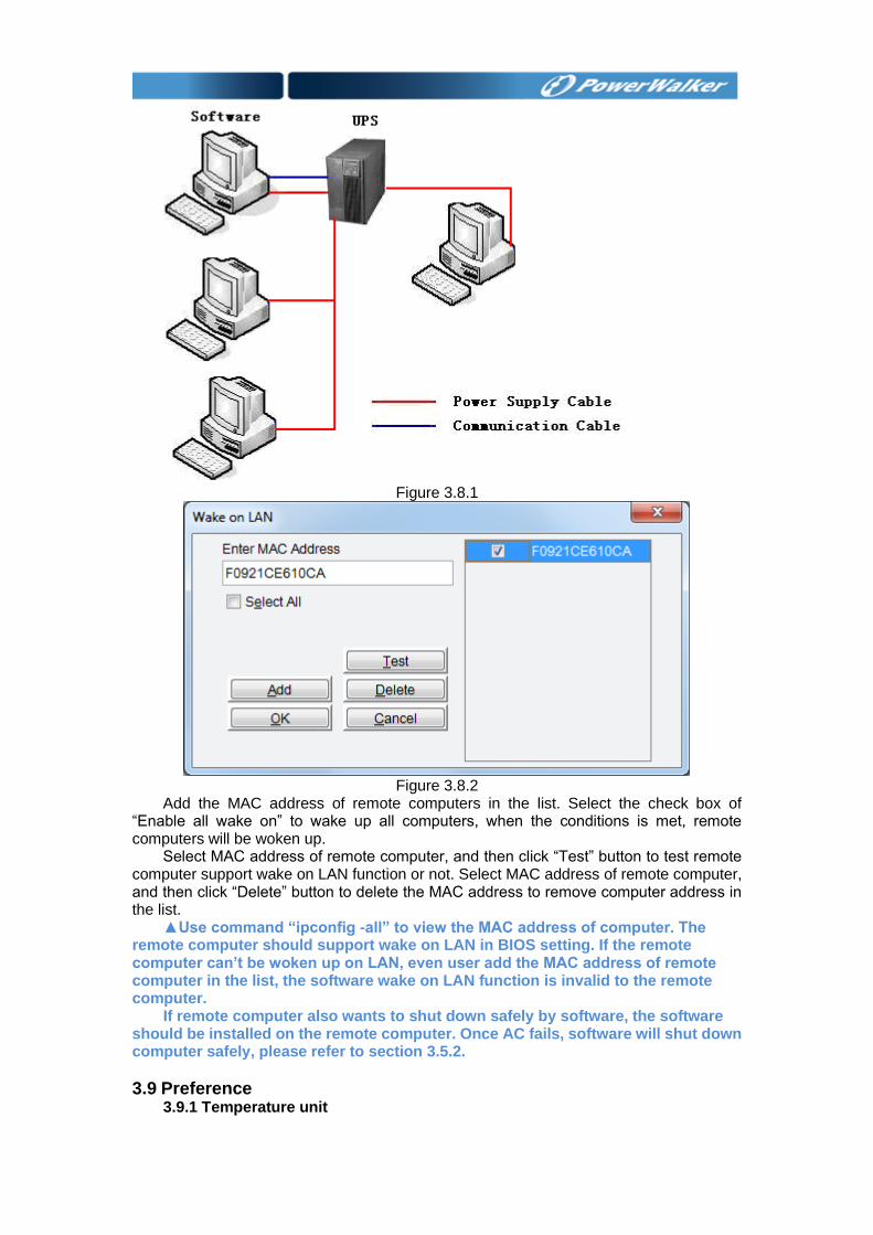
Figure 3.8.1
Figure 3.8.2
Add the MAC address of remote computers in the list. Select the check box of “Enable all wake on” to wake up all computers, when the conditions is met, remote computers will be woken up.
Select MAC address of remote computer, and then click “Test” button to test remote computer support wake on LAN function or not. Select MAC address of remote computer, and then click “Delete” button to delete the MAC address to remove computer address in the list.
▲Use command “ipconfig -all” to view the MAC address of computer. The remote computer should support wake on LAN in BIOS setting. If the remote computer can’t be woken up on LAN, even user add the MAC address of remote computer in the list, the software wake on LAN function is invalid to the remote computer.
If remote computer also wants to shut down safely by software, the software should be installed on the remote computer. Once AC fails, software will shut down computer safely, please refer to section 3.5.2.
3.9 Preference 3.9.1 Temperature unit
User can select temperature unit according to personal habit, click “Temp” item of
“Preference” menu to select: Centigrade (C) or Fahrenheit (F).
3.9.2 Date format User can select date format, click “DateFormat” item of “Preference” menu to
select: year/month/day, month/day/year or day/month/year.
3.9.3 Bottom Image
User can set different by clicking “BottomImage” item of “Preference” menu.
3.9.4 Advance Settings
User can set the attribute of software interface and the attribute of bottom image by clicking “Advance Settings” item of “Preference” menu.
3.10 Language Software supports many kinds of languages: “English”, “German”, “French”, “Italian”,
“Spanish”, “Polish”, “Turkish”, “Russian”, “Portuguese”, “Japanese” and “Thai”, user can change language via “Language” menu.
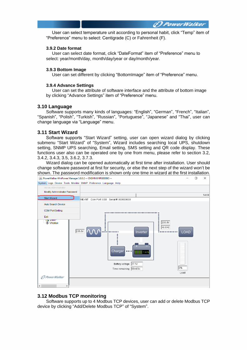
3.11 Start Wizard Software supports “Start Wizard” setting, user can open wizard dialog by clicking
submenu “Start Wizard” of “System”, Wizard includes searching local UPS, shutdown setting, SNMP UPS searching, Email setting, SMS setting and QR code display. These functions user also can be operated one by one from menu, please refer to section 3.2, 3.4.2, 3.4.3, 3.5, 3.6.2, 3.7.3.
Wizard dialog can be opened automatically at first time after installation. User should change software password at first for security, or else the next step of the wizard won’t be shown. The password modification is shown only one time in wizard at the first installation.
3.12 Modbus TCP monitoring Software supports up to 4 Modbus TCP devices, user can add or delete Modbus TCP
device by clicking “Add/Delete Modbus TCP” of “System”.
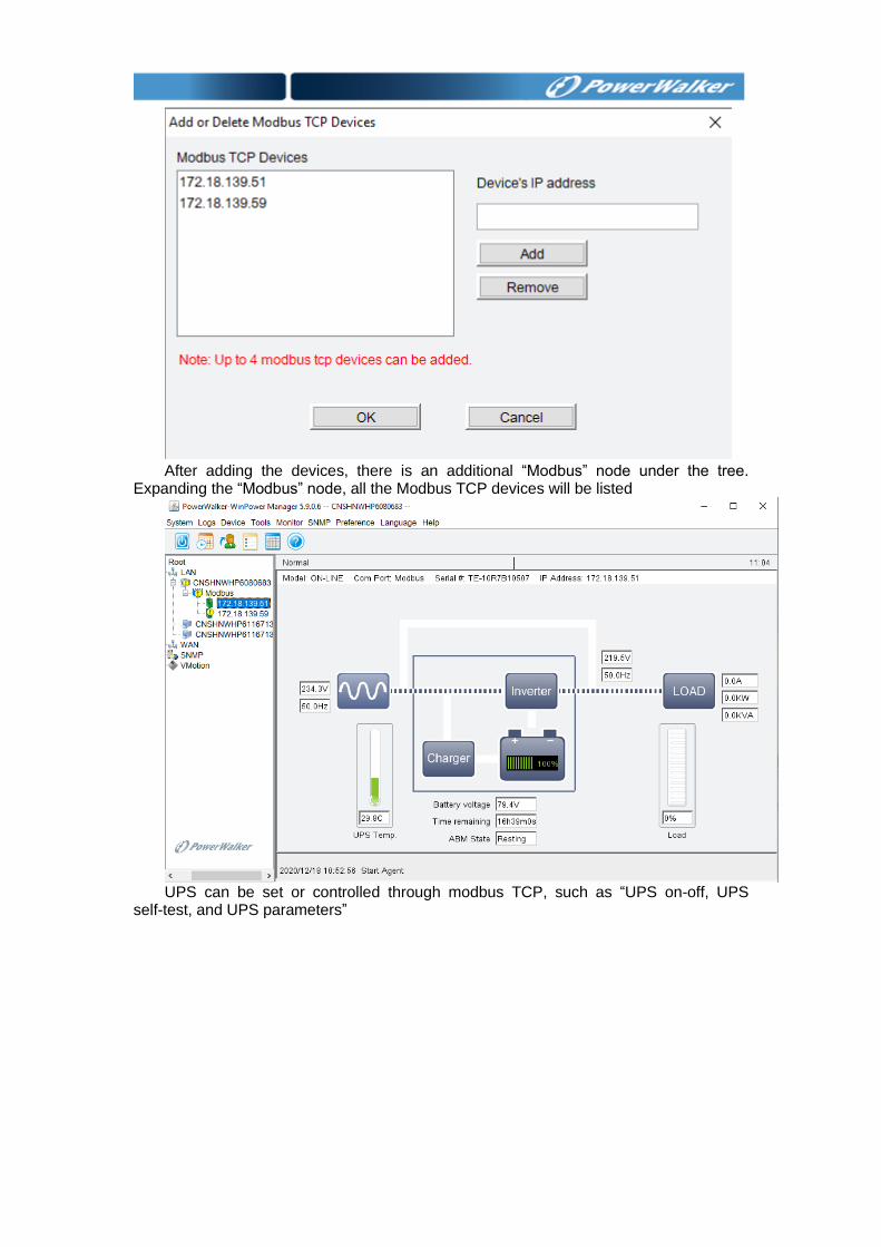
After adding the devices, there is an additional “Modbus” node under the tree.
Expanding the “Modbus” node, all the Modbus TCP devices will be listed
UPS can be set or controlled through modbus TCP, such as “UPS on-off, UPS
self-test, and UPS parameters”
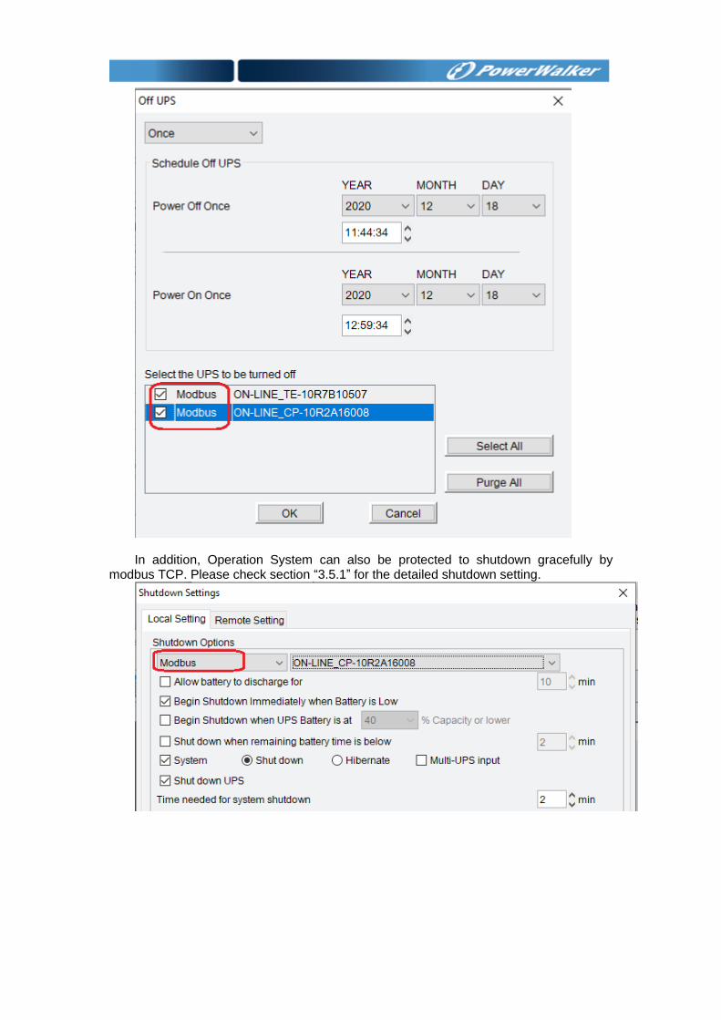
In addition, Operation System can also be protected to shutdown gracefully by
modbus TCP. Please check section “3.5.1” for the detailed shutdown setting.
Chapter 4 Frequent questions 4.1 How to do if software port is in use by other software
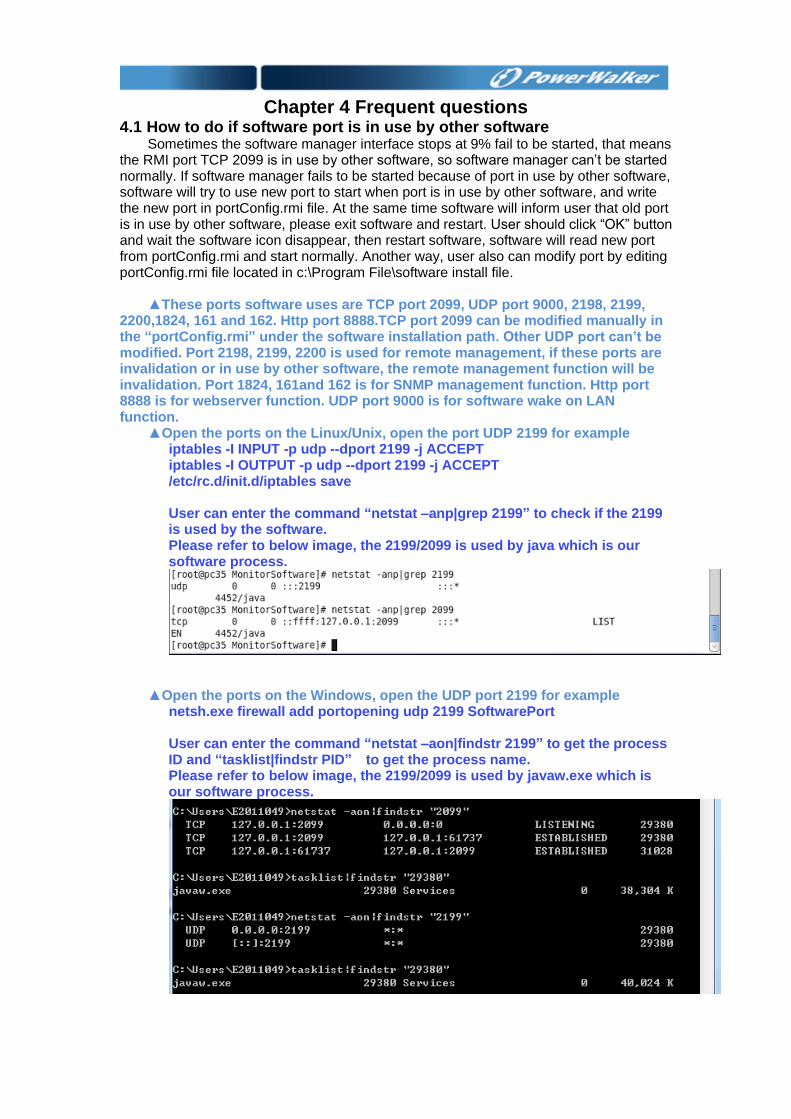
Sometimes the software manager interface stops at 9% fail to be started, that means the RMI port TCP 2099 is in use by other software, so software manager can’t be started normally. If software manager fails to be started because of port in use by other software, software will try to use new port to start when port is in use by other software, and write the new port in portConfig.rmi file. At the same time software will inform user that old port is in use by other software, please exit software and restart. User should click “OK” button and wait the software icon disappear, then restart software, software will read new port from portConfig.rmi and start normally. Another way, user also can modify port by editing portConfig.rmi file located in c:\Program File\software install file.
▲These ports software uses are TCP port 2099, UDP port 9000, 2198, 2199,
2200,1824, 161 and 162. Http port 8888.TCP port 2099 can be modified manually in the “portConfig.rmi” under the software installation path. Other UDP port can’t be modified. Port 2198, 2199, 2200 is used for remote management, if these ports are invalidation or in use by other software, the remote management function will be invalidation. Port 1824, 161and 162 is for SNMP management function. Http port 8888 is for webserver function. UDP port 9000 is for software wake on LAN function.
▲Open the ports on the Linux/Unix, open the port UDP 2199 for example iptables -I INPUT -p udp --dport 2199 -j ACCEPT iptables -I OUTPUT -p udp --dport 2199 -j ACCEPT /etc/rc.d/init.d/iptables save User can enter the command “netstat –anp|grep 2199” to check if the 2199 is used by the software. Please refer to below image, the 2199/2099 is used by java which is our software process.
▲Open the ports on the Windows, open the UDP port 2199 for example netsh.exe firewall add portopening udp 2199 SoftwarePort User can enter the command “netstat –aon|findstr 2199” to get the process ID and “tasklist|findstr PID” to get the process name. Please refer to below image, the 2199/2099 is used by javaw.exe which is our software process.
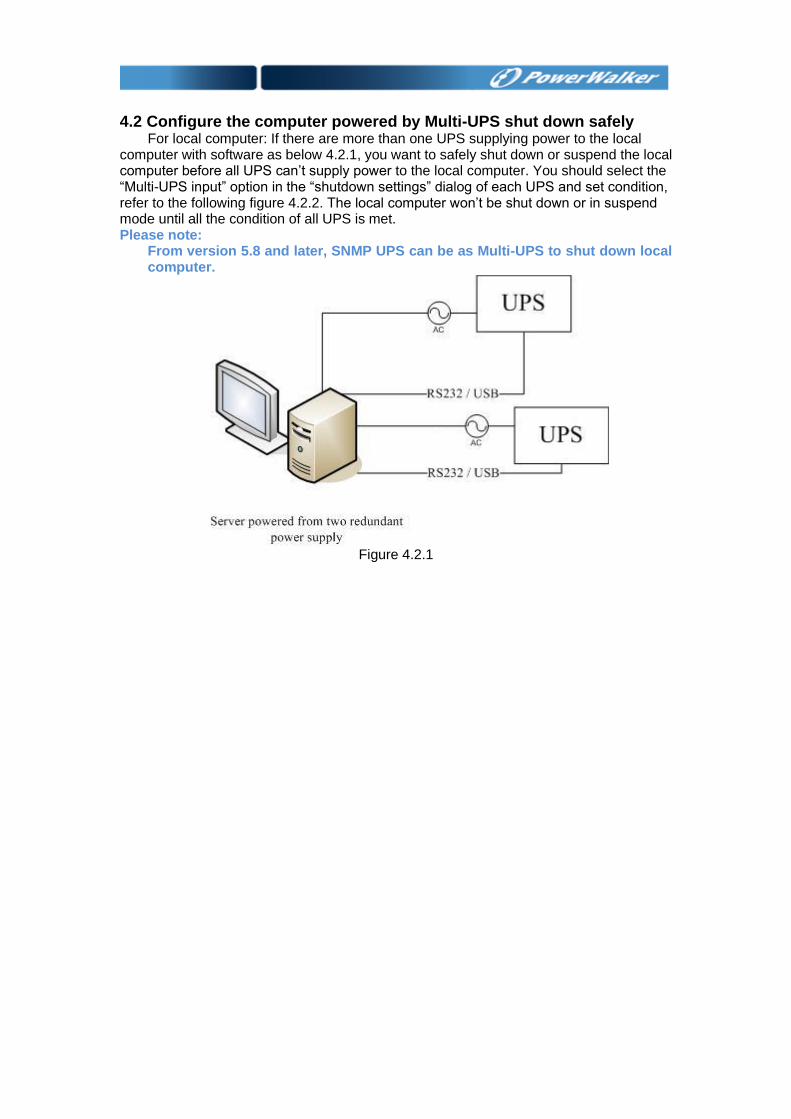
4.2 Configure the computer powered by Multi-UPS shut down safely For local computer: If there are more than one UPS supplying power to the local
computer with software as below 4.2.1, you want to safely shut down or suspend the local computer before all UPS can’t supply power to the local computer. You should select the “Multi-UPS input” option in the “shutdown settings” dialog of each UPS and set condition, refer to the following figure 4.2.2. The local computer won’t be shut down or in suspend mode until all the condition of all UPS is met. Please note:
From version 5.8 and later, SNMP UPS can be as Multi-UPS to shut down local computer.
Figure 4.2.1
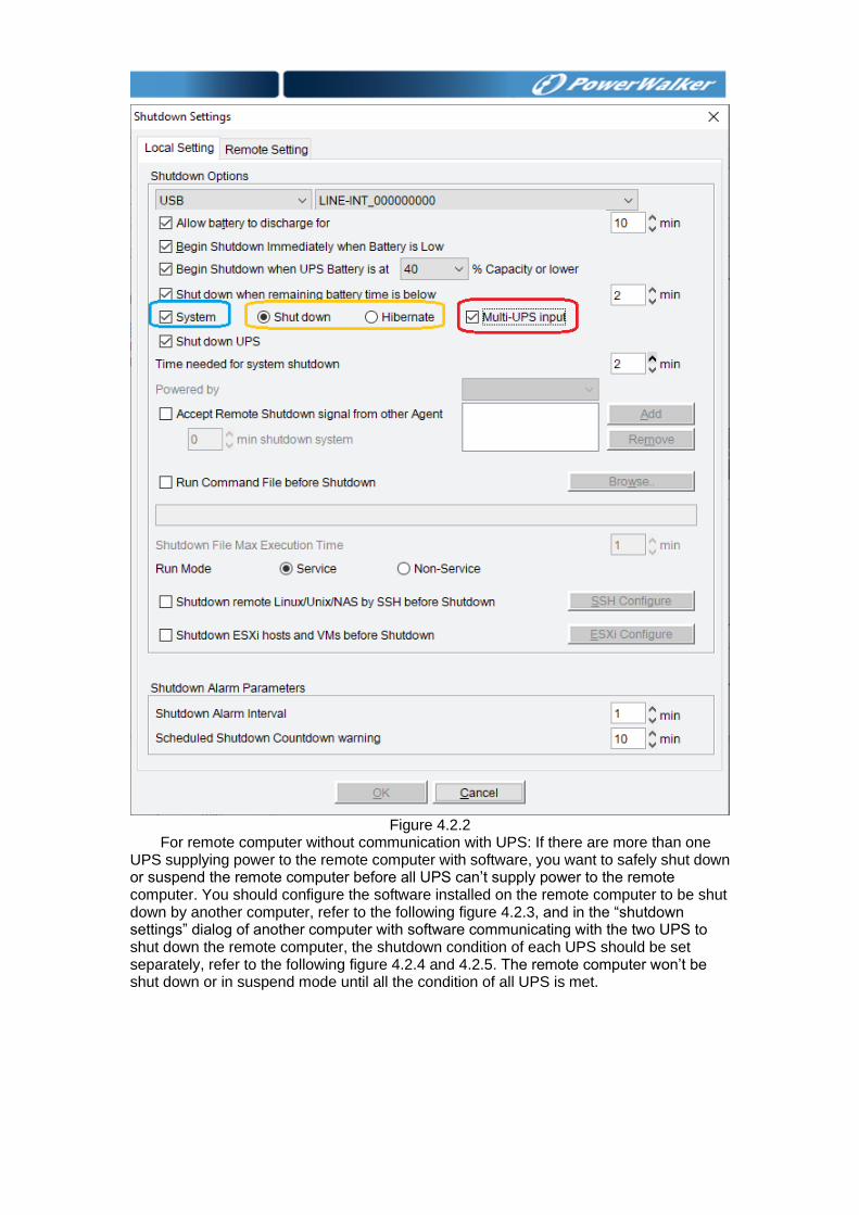
Figure 4.2.2
For remote computer without communication with UPS: If there are more than one UPS supplying power to the remote computer with software, you want to safely shut down or suspend the remote computer before all UPS can’t supply power to the remote computer. You should configure the software installed on the remote computer to be shut down by another computer, refer to the following figure 4.2.3, and in the “shutdown settings” dialog of another computer with software communicating with the two UPS to shut down the remote computer, the shutdown condition of each UPS should be set separately, refer to the following figure 4.2.4 and 4.2.5. The remote computer won’t be shut down or in suspend mode until all the condition of all UPS is met.
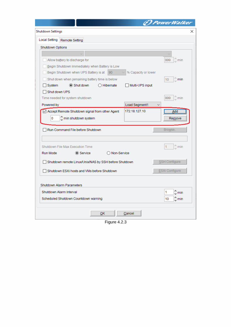
Figure 4.2.3
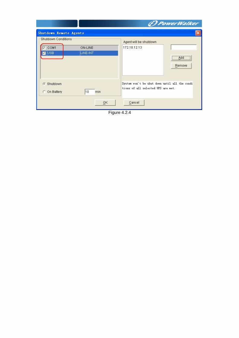
Figure 4.2.4
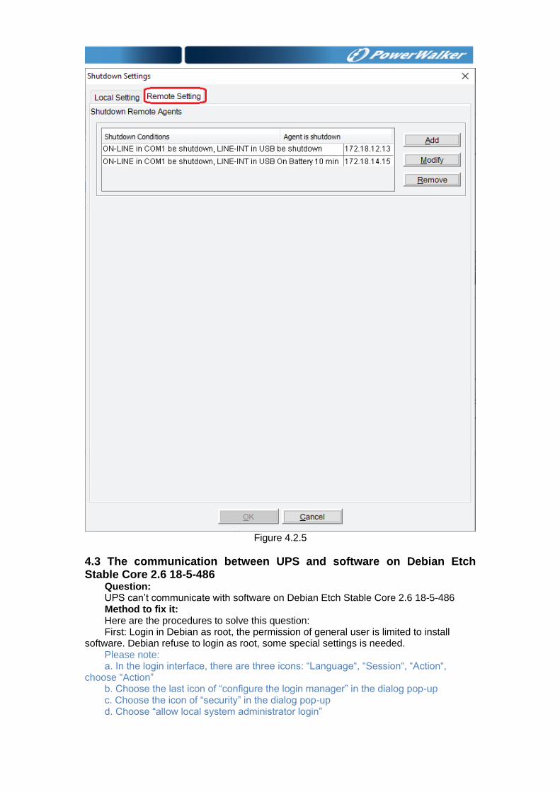
Figure 4.2.5
4.3 The communication between UPS and software on Debian Etch Stable Core 2.6 18-5-486
Question: UPS can’t communicate with software on Debian Etch Stable Core 2.6 18-5-486 Method to fix it: Here are the procedures to solve this question: First: Login in Debian as root, the permission of general user is limited to install
software. Debian refuse to login as root, some special settings is needed. Please note: a. In the login interface, there are three icons: “Language“, “Session“, “Action“,
choose “Action” b. Choose the last icon of “configure the login manager” in the dialog pop-up c. Choose the icon of “security” in the dialog pop-up d. Choose “allow local system administrator login”
Second: Input the user name of root and the password, and then install monitoring
software manually. Use the command “./agent start” to start software service, and then use the command “./monitor” to start the monitor interface.
Finally: Copy the document of s99UPS from Linux (attached CD) to /etc/rcS.d, The file s99UPS is used to start software service automatically. When the computer
reboots, software service will be started automatically, user only need to start the monitor interface by the command “./monitor”.
Please note: a. If the third step is executed, no matter what the user login in as root or a general
user, the communication with UPS will be successful. b. If the third step have not been executed, you should login as root, and use the
command “./agent start” to start software service. If login in as a general user, the communication with UPS will be failed
4.4 The communication between UPS and software on RedHat Core 2.6 9
Question: UPS can’t communicate with software on RedHat Core 2.6 9 Method to fix it: Add the word of “none /proc/bus/usb usbdevfs defaults 0 0” to the document
“/etc/fstab”, software will find the UPS when choose the item of “Auto Search Device”.
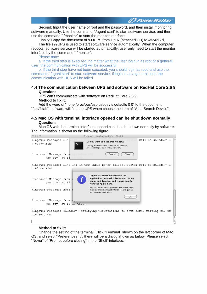
4.5 Mac OS with terminal interface opened can be shut down normally
Question: Mac OS with the terminal interface opened can’t be shut down normally by software.
The information is shown as the following figure.
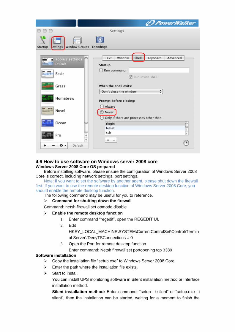
Method to fix it: Change the setting of the terminal: Click “Terminal” shown on the left corner of Mac
OS, and select “Preferences…”, there will be a dialog shown as below. Please select “Never” of “Prompt before closing” in the “Shell” interface.
Reboots the computer, t
4.6 How to use software on Windows server 2008 core Windows Server 2008 Core OS prepared
Before installing software, please ensure the configuration of Windows Server 2008 Core is correct, including network settings, port settings.
Note: if you want to set the software by another agent, please shut down the firewall first. If you want to use the remote desktop function of Windows Server 2008 Core, you should enable the remote desktop function.
The following command may be useful for you to reference.
➢ Command for shutting down the firewall
Command: netsh firewall set opmode disable
➢ Enable the remote desktop function
1. Enter command “regedit”, open the REGEDIT UI.
2. Edit
HKEY_LOCAL_MACHINE\SYSTEM\CurrentControlSet\Control\Termin
al Server\fDenyTSConnections = 0
3. Open the Port for remote desktop function
Enter command: Netsh firewall set portopening tcp 3389
Software installation
➢ Copy the installation file “setup.exe” to Windows Server 2008 Core.
➢ Enter the path where the installation file exists.
➢ Start to install.
You can install UPS monitoring software in Silent installation method or Interface
installation method.
Silent installation method: Enter command: “setup –i silent” or “setup.exe –i
silent”, then the installation can be started, waiting for a moment to finish the
installation.
Interface installation method: Enter command: “setup” or “setup.exe”, then the
installation can be started, please follow “next” button of interface to finish the
installation.
➢ Check if the installation is successful:
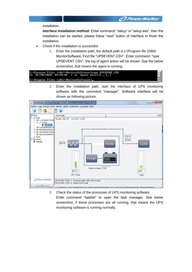
1. Enter the installation path, the default path is c:\Program file (X86)\
MonitorSoftware, Find file “UPSEVENT.CSV”, Enter command: “type
UPSEVENT.CSV”, the log of agent action will be shown. See the below
screenshot, that means the agent is running.
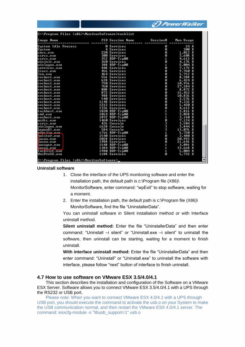
2. Enter the installation path, start the interface of UPS monitoring
software with the command “manager”. Software interface will be
shown as following picture.
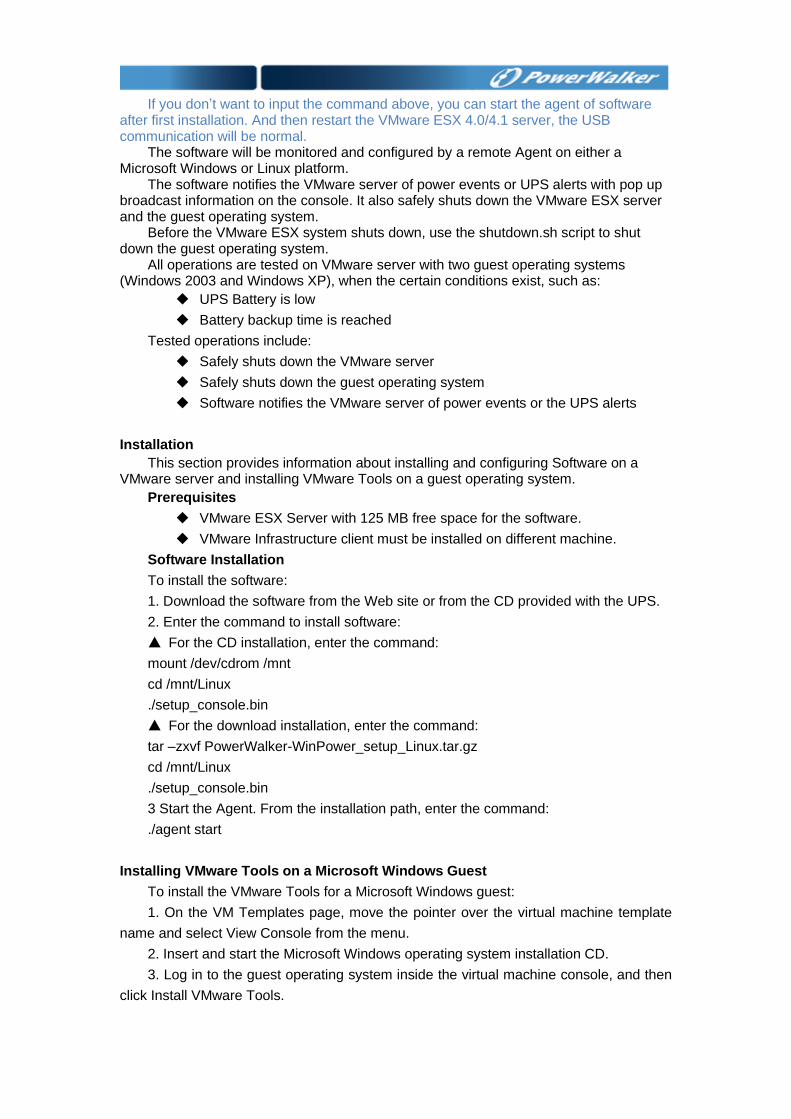
3. Check the status of the processes of UPS monitoring software.
Enter command “tasklist” to open the task manager. See below
screenshot, if these processes are all running, that means the UPS
monitoring software is running normally.
Uninstall software
1. Close the interface of the UPS monitoring software and enter the
installation path, the default path is c:\Program file (X86)\
MonitorSoftware, enter command: “wpExit” to stop software, waiting for
a moment.
2. Enter the installation path, the default path is c:\Program file (X86)\
MonitorSoftware, find the file “UninstallerData”.
You can uninstall software in Silent installation method or with Interface
uninstall method.
Silent uninstall method: Enter the file “UninstallerData” and then enter
command: “Uninstall –i silent” or “Uninstall.exe –i silent” to uninstall the
software, then uninstall can be starting, waiting for a moment to finish
uninstall.
With interface uninstall method: Enter the file “UninstallerData” and then
enter command: “Uninstall” or “Uninstall.exe” to uninstall the software with
interface, please follow “next” button of interface to finish uninstall.
4.7 How to use software on VMware ESX 3.5/4.0/4.1 This section describes the installation and configuration of the Software on a VMware
ESX Server. Software allows you to connect VMware ESX 3.5/4.0/4.1 with a UPS through the RS232 or USB port.
Please note: When you want to connect VMware ESX 4.0/4.1 with a UPS through USB port, you should execute the command to activate the usb.o on your System to make the USB communication normal, and then restart the VMware ESX 4.0/4.1 server. The command: esxcfg-module -s "libusb_support=1" usb.o
If you don’t want to input the command above, you can start the agent of software
after first installation. And then restart the VMware ESX 4.0/4.1 server, the USB communication will be normal.
The software will be monitored and configured by a remote Agent on either a Microsoft Windows or Linux platform.
The software notifies the VMware server of power events or UPS alerts with pop up broadcast information on the console. It also safely shuts down the VMware ESX server and the guest operating system.
Before the VMware ESX system shuts down, use the shutdown.sh script to shut down the guest operating system.
All operations are tested on VMware server with two guest operating systems (Windows 2003 and Windows XP), when the certain conditions exist, such as:
◆ UPS Battery is low
◆ Battery backup time is reached
Tested operations include:
◆ Safely shuts down the VMware server
◆ Safely shuts down the guest operating system
◆ Software notifies the VMware server of power events or the UPS alerts
Installation
This section provides information about installing and configuring Software on a VMware server and installing VMware Tools on a guest operating system.
Prerequisites
◆ VMware ESX Server with 125 MB free space for the software.
◆ VMware Infrastructure client must be installed on different machine.
Software Installation
To install the software:
1. Download the software from the Web site or from the CD provided with the UPS.
2. Enter the command to install software:
▲ For the CD installation, enter the command:
mount /dev/cdrom /mnt
cd /mnt/Linux
./setup_console.bin
▲ For the download installation, enter the command:
tar –zxvf PowerWalker-WinPower_setup_Linux.tar.gz
cd /mnt/Linux
./setup_console.bin
3 Start the Agent. From the installation path, enter the command:
./agent start
Installing VMware Tools on a Microsoft Windows Guest
To install the VMware Tools for a Microsoft Windows guest:
1. On the VM Templates page, move the pointer over the virtual machine template
name and select View Console from the menu.
2. Insert and start the Microsoft Windows operating system installation CD.
3. Log in to the guest operating system inside the virtual machine console, and then
click Install VMware Tools.
4. From within the guest operating system, click OK to confirm that you want to install
VMware Tools and launch the Install Shield wizard.
▲ If auto-run is enabled in the guest operating system (the default setting for
Microsoft Windows operating systems), a window opens.
▲ If auto-run is not enabled, run the VMware Tools installer. Click Start > Run and
enter D:\setup.exe, where D: is the first virtual CD-ROM drive.
5. Follow the on-screen instructions.
▲ On Microsoft Windows Server 2003, the SVGA driver is installed automatically,
and the guest operating system uses it after it reboots.
▲ After you install VMware Tools, Microsoft Windows 2000 and Microsoft
Windows XP guest operating systems must be rebooted to use the new driver.
Installing VMware Tools on a Linux Guest
The VMware Tools installation package is on the VMware server installation CD on
the path \VMware\RPMS.
To install the VMware Tools for a Linux guest:
1. On the VM Templates page, move the pointer over the virtual machine template
name and select View Console from the menu.
2. Insert and start the VMware server installation CD.
3. Log in to the guest operating system inside the virtual machine console, and then
click Install VMware Tools.
4. Mount the CD with the command:
mount /dev/cdrom /mnt
5. Install the package with the command:
cd /mnt/VMware/RPMS
rpm –Uvh VMware-esx-tools-***.i386.rpm
NOTE: The package name is likely to be different.
6. Configure the VMware Tools with the command:
Vmware-config-tools.pl
7. Enter number: 1
8. Start the VMware Tools with the command:
Vmware-toolbox &
VMware Tools on the summary row displays OK, if the tools are available (refer to
the following figure 4.7.1):
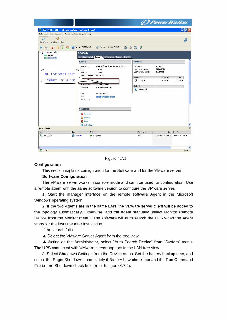
Figure 4.7.1
Configuration
This section explains configuration for the Software and for the VMware server.
Software Configuration
The VMware server works in console mode and can’t be used for configuration. Use
a remote agent with the same software version to configure the VMware server.
1. Start the manager interface on the remote software Agent in the Microsoft
Windows operating system.
2. If the two Agents are in the same LAN, the VMware server client will be added to
the topology automatically. Otherwise, add the Agent manually (select Monitor Remote
Device from the Monitor menu). The software will auto search the UPS when the Agent
starts for the first time after installation.
If the search fails:
▲ Select the VMware Server Agent from the tree view.
▲ Acting as the Administrator, select “Auto Search Device” from “System” menu.
The UPS connected with VMware server appears in the LAN tree view.
3. Select Shutdown Settings from the Device menu. Set the battery backup time, and
select the Begin Shutdown Immediately if Battery Low check box and the Run Command
File before Shutdown check box (refer to figure 4.7.2).
OK indicates that
VMware Tools are
available
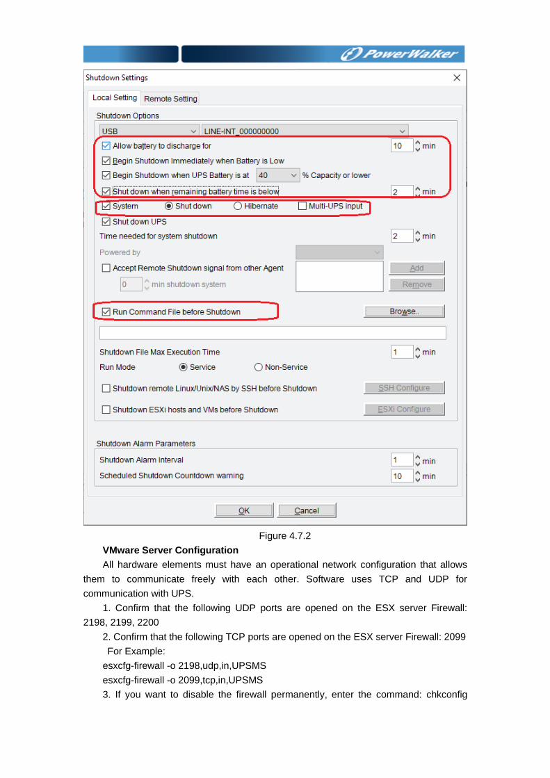
Figure 4.7.2
VMware Server Configuration
All hardware elements must have an operational network configuration that allows
them to communicate freely with each other. Software uses TCP and UDP for
communication with UPS.
1. Confirm that the following UDP ports are opened on the ESX server Firewall:
2198, 2199, 2200
2. Confirm that the following TCP ports are opened on the ESX server Firewall: 2099
For Example:
esxcfg-firewall -o 2198,udp,in,UPSMS
esxcfg-firewall -o 2099,tcp,in,UPSMS
3. If you want to disable the firewall permanently, enter the command: chkconfig

iptables off
4.To disable the firewall temporarily, enter the command: service iptables stop
4.8 How to use software on VMware ESXi OS Please refer to the document: UserManual_for_VMwareESXi.pdf
Chapter 5 Software Secure Usage statement 1. Login password is encrypting using AES during transmission over the network to
ensure remote network security access.
2. Use HTTPS instead of HTTP access web and APP function, Use Web Socket over
SSL for pushing message to APP to ensure network security access.
3. Re-authenticate the user before modifying the password to ensure security access
4. Set the login timeout for 1 hour, if the application is not active, when user wants to
operate software via manager/web/app, there will be message prompted that software
should need to re-login after an hour login timeout.
5. Encrypt JAVA RMI with SSL to ensure software running safely
6. User can get the inventory from the device including Location, IP address, Model,
device status, Link, serial number. (refer to section 3.2 to get more information)
7. Software can only support three physical access ports with UPS: USB (maximize
number 32), RS232/USBtoRS232(maximize number 4) and SNMP card.
Do not connect unauthorized USB device or SD card for any operation.
8. Software support Administrator account (the default password is “Administrator”) and
ordinary account.
Administrator account can set all the parameters, set the UPS on/off schedule, control
the UPS, export/delete the log and so on. ordinary account has the read-only
privilege.
The SNMP Public community is “public” as default
9. Software use TCP port 2099 for local agent. it uses UDP port 2198, 2199, 2200 for
host-to-host remote communication.it use UDP 1824, 161 and 162 for SNMP function.
It uses 8888 for web-server. (refer to section 4.1 to get more information for how to
open/check the port on the Windows/Linux/Unix)
Software service is UPSmonitor in the Services list
10. Software will log the device data and events: All the data is saved in “UPSDATA.CSV”
under the software installation path, All the events are saved in “UPSEVENT.CSV”
and “SNMPEVENT.CSV” under the software installation path. (refer to section 3.3.7
for more information about how to set/check/export the data and events)
11. Software can’t support update the software on-line. All the parameters are saved in
“UPSPILOT.CFG” under the installation path. User can copy this document to take
back up of the configurations or User can choose “Yes” when the installation guide
shown “Would you like to keep the old configuration settings?”.
12. Refer to section 2.4 for more information about uninstalling the software
Appendix A - The detail information about glossary
1. Agent --- A service program running on the background. 2. UPS battery low --- When AC fails, UPS works on battery, when the battery level is under than some value, UPS will give battery low warning. 3. UPS battery backup time --- When AC fails, how much time UPS can work on battery. Battery backup time exhausted means that the time UPS works on battery is longer than the time set in the “UPS shutdown parameter”. 4. UPS overload --- the load is above 110 %. 5. UPS works on bypass --- UPS can’t work on inverter because of hardware fault or other reasons, at that time, UPS will work on bypass, when AC fails, there will no output immediately. 6. UPS battery self-test --- UPS mode changes from normal mode to battery mode for some time, and then return to normal mode. The purpose of battery self-test is to check the battery OK or not. 7. UPS battery self-test fail --- UPS can’t work on battery mode normally, user should check battery connect or not, or battery will need to be changed. 8. Shutdown File Max Execution Time --- The time for agent starts to execute file before beginning to save applications and shutting down OS. 9. The time for shutdown OS --- The UPS output will be shut down when the time exhausted 10. Accept other agent shutdown signal --- When the UPS communicating with remote agent is abnormal, the remote agent will send shutdown signal to the agent. 11. The warning start time for shutdown schedule --- The start time software will give warning information to user, if user has set shutdown schedule 12. The warning interval for shutdown --- The interval of warning after software starts to give shutdown warning
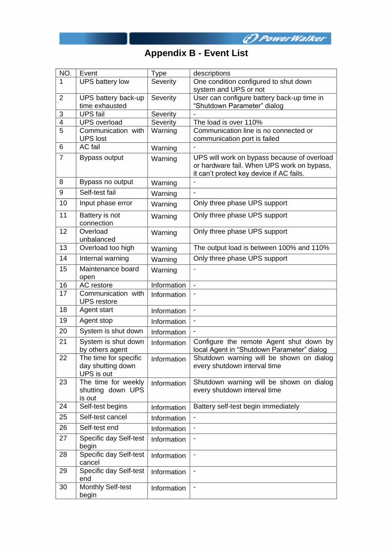
Appendix B - Event List
NO. Event Type descriptions
1 UPS battery low Severity One condition configured to shut down system and UPS or not
2 UPS battery back-up time exhausted
Severity User can configure battery back-up time in “Shutdown Parameter” dialog
3 UPS fail Severity -
4 UPS overload Severity The load is over 110%
5 Communication with UPS lost
Warning Communication line is no connected or communication port is failed
6 AC fail Warning -
7 Bypass output Warning UPS will work on bypass because of overload or hardware fail. When UPS work on bypass, it can’t protect key device if AC fails.
8 Bypass no output Warning -
9 Self-test fail Warning -
10 Input phase error Warning Only three phase UPS support
11 Battery is not connection
Warning Only three phase UPS support
12 Overload unbalanced
Warning Only three phase UPS support
13 Overload too high Warning The output load is between 100% and 110%
14 Internal warning Warning Only three phase UPS support
15 Maintenance board open
Warning -
16 AC restore Information -
17 Communication with UPS restore
Information -
18 Agent start Information -
19 Agent stop Information -
20 System is shut down Information -
21 System is shut down by others agent
Information Configure the remote Agent shut down by local Agent in “Shutdown Parameter” dialog
22 The time for specific day shutting down UPS is out
Information Shutdown warning will be shown on dialog every shutdown interval time
23 The time for weekly shutting down UPS is out
Information Shutdown warning will be shown on dialog every shutdown interval time
24 Self-test begins Information Battery self-test begin immediately
25 Self-test cancel Information -
26 Self-test end Information -
27 Specific day Self-test begin
Information -
28 Specific day Self-test cancel
Information -
29 Specific day Self-test end
Information -
30 Monthly Self-test begin
Information -

31 Monthly Self-test
cancel Information -
32 Monthly Self-test end
Information -


![User Guide...User. {{]}]} {}]}](https://img.dokumen.tips/doc/110x75/60918ca14327954d24291644/-user-guide-user-.jpg)